Embed Size (px)
DESCRIPTION
GENERAL CATALOGUE - CABLING SYSTEMS
Citation preview


G E N E R A L C A T A L O G U E
CABLING SYSTEMS
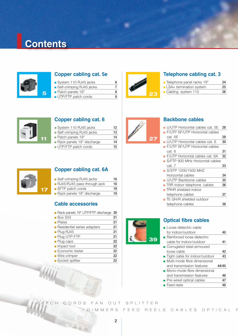
Contents
2
P A T C H C O R D S F A N O U T S P L I T T E R
D I M M E R S F E E D R E E L S C A B L E S O P T I C A L F
Copper cabling cat. 5en System 110 RJ45 jacks 6n Self-crimping RJ45 jacks 7n Patch panels 19" 8n UTP/FTP patch cords 9
5
Copper cabling cat. 6n System 110 RJ45 jacks 12n Self-crimping RJ45 jacks 13n Patch panels 19" 14n Rack panels 19" discharge 14n UTP/FTP patch cords 15
11
Copper cabling cat. 6A
n Self-crimping RJ45 jacks 18n RJ45/RJ45 pass through jack 18n SFTP patch cords 19n Rack panels 19" discharge 19
n Rack panels 19" UTP/FTP discharge 20n Box 503 21n Plates 21n Residential series adapters 21n Plug RJ45 21n Plug UTP-FTP 21n Plug caps 22n Impact tool 22n Economic tester 22n Wire crimper 22n Socket splitter 22
17
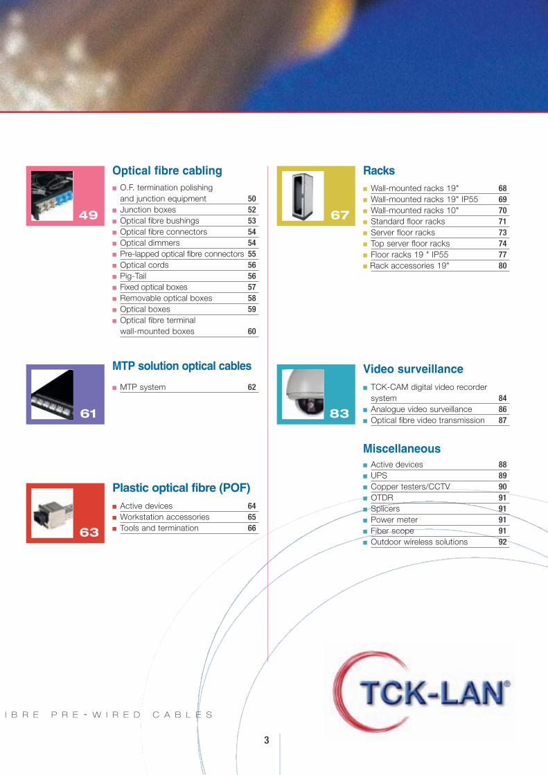
Telephone cabling cat. 3n Telephone panel racks 19" 24n LSA+ termination system 25n Cabling system 110 2623
Backbone cablesn U/UTP Horizontal cables cat. 5E 28n F/UTP SF/UTP Horizontal cables
cat. 5E 29n U/UTP Horizontal cables cat. 6 30n F/UTP SF/UTP Horizontal cables
cat. 6 31n F/UTP Horizontal cables cat. 6A 32n S/FTP 900 MHz Horizontal cables
cat. 7 33n S/STP 1200/1500 MHZ
Horizontal cables 34n U/UTP Backbone cables 35n TRR indoor telephone cables 36n TRHR shielded indoor
telephone cables 37n TE GH/R shielded outdoor
telephone cables 38
27
Optical fibre cablesn Loose dielectric cable
for indoor/outdoor 40n Reinforced loose dielectric
cable for indoor/outdoor 41n Corrugated steel armoured
loose cable 42n Tight cable for indoor/outdoor 43n Multi-mode fibre dimensional
and transmission features 44/45n Mono-mode fibre dimensional
and transmission features 46n Pre-wired optical cables 47n Feed reels 48
39
Cable accessories
3
I B R E P R E - W I R E D C A B L E S
Optical fibre cablingn O.F. termination polishing
and junction equipment 50n Junction boxes 52n Optical fibre bushings 53n Optical fibre connectors 54n Optical dimmers 54n Pre-lapped optical fibre connectors 55n Optical cords 56n Pig-Tail 56n Fixed optical boxes 57n Removable optical boxes 58n Optical boxes 59n Optical fibre terminal
wall-mounted boxes 60
49
MTP solution optical cables
n MTP system 62
61
Racksn Wall-mounted racks 19" 68n Wall-mounted racks 19" IP55 69n Wall-mounted racks 10" 70n Standard floor racks 71n Server floor racks 73n Top server floor racks 74n Floor racks 19 " IP55 77n Rack accessories 19" 80
67
Plastic optical fibre (POF)n Active devices 64n Workstation accessories 65n Tools and termination 6663
Video surveillancen TCK-CAM digital video recorder
system 84n Analogue video surveillance 86n Optical fibre video transmission 87
n Active devices 88n UPS 89n Copper testers/CCTV 90n OTDR 91n Splicers 91n Power meter 91n Fiber scope 91n Outdoor wireless solutions 92
83
Miscellaneous

After creating a structured cabling system using TCK-LAN®
brand products only, the certifiedtechnician can send in systemcharacteristics and apply for a25-year warranty.Please note that all cablingcomponents meet internationalRoHS and WEEE environmentalstandards.All current regulations such as TIA/EIA568A/B, ISO 11801,EN50173, IEEE 802.Eab are met.
rogramwarranty/certifications
P
4
TCK-LAN® provides networktechnicians with training on
structured cabling systems toguarantee optimal installation
quality. TCK-LAN® coursestrain participants on leading
copper and fibre productapplications.
opper cabling cat. 5e
C
Structured cabling is a group oftransmission components that areinstalled and meet certain specificationsdefined by international standards.TCK-LAN® is a structured cablingcomponent brand: it identifies a widerange of products required to buildcomplete copper systems for LAN andWAN networks and residential cabling.The TCK-LAN® cabling system cat. 5e wasdesigned to easily meet all requirementsset for the most demanding applicationsin accordance with ANSI/TIA/EIA568 B.1 and 568 B.2, ISO/IEC 11801 (2 nd ed/classed) and EN50173 standards.25-year warranty on cabling completedand installed by qualified companies
.
6
COPPER CABLING CAT 5E
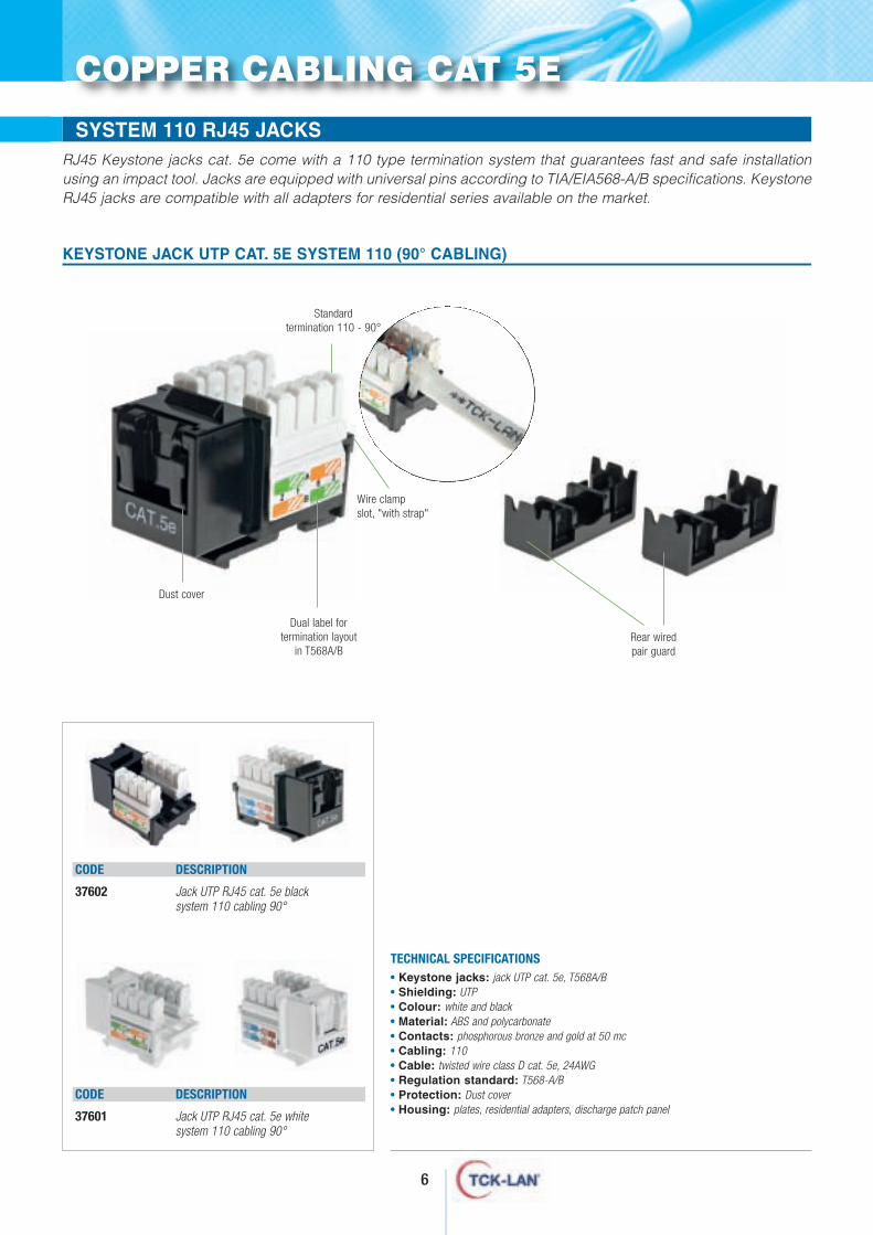
RJ45 LINE JACKS - Keystone jack UTP cat. 5e system 110SYSTEM 110 RJ45 JACKS
• Keystone jacks: jack UTP cat. 5e, T568A/B • Shielding: UTP• Colour: white and black• Material: ABS and polycarbonate• Contacts: phosphorous bronze and gold at 50 mc• Cabling: 110 • Cable: twisted wire class D cat. 5e, 24AWG• Regulation standard: T568-A/B• Protection: Dust cover• Housing: plates, residential adapters, discharge patch panel
RJ45 Keystone jacks cat. 5e come with a 110 type termination system that guarantees fast and safe installationusing an impact tool. Jacks are equipped with universal pins according to TIA/EIA568-A/B specifications. KeystoneRJ45 jacks are compatible with all adapters for residential series available on the market.
TECHNICAL SPECIFICATIONS
KEYSTONE JACK UTP CAT. 5E SYSTEM 110 (90° CABLING)
CODE DESCRIPTION
37602 Jack UTP RJ45 cat. 5e blacksystem 110 cabling 90°
CODE DESCRIPTION
37601 Jack UTP RJ45 cat. 5e whitesystem 110 cabling 90°
Dust cover
Wire clampslot, "with strap"
Dual label fortermination layout
in T568A/BRear wired pair guard
Standardtermination 110 - 90°
7
COPPER CABLING CAT 5E
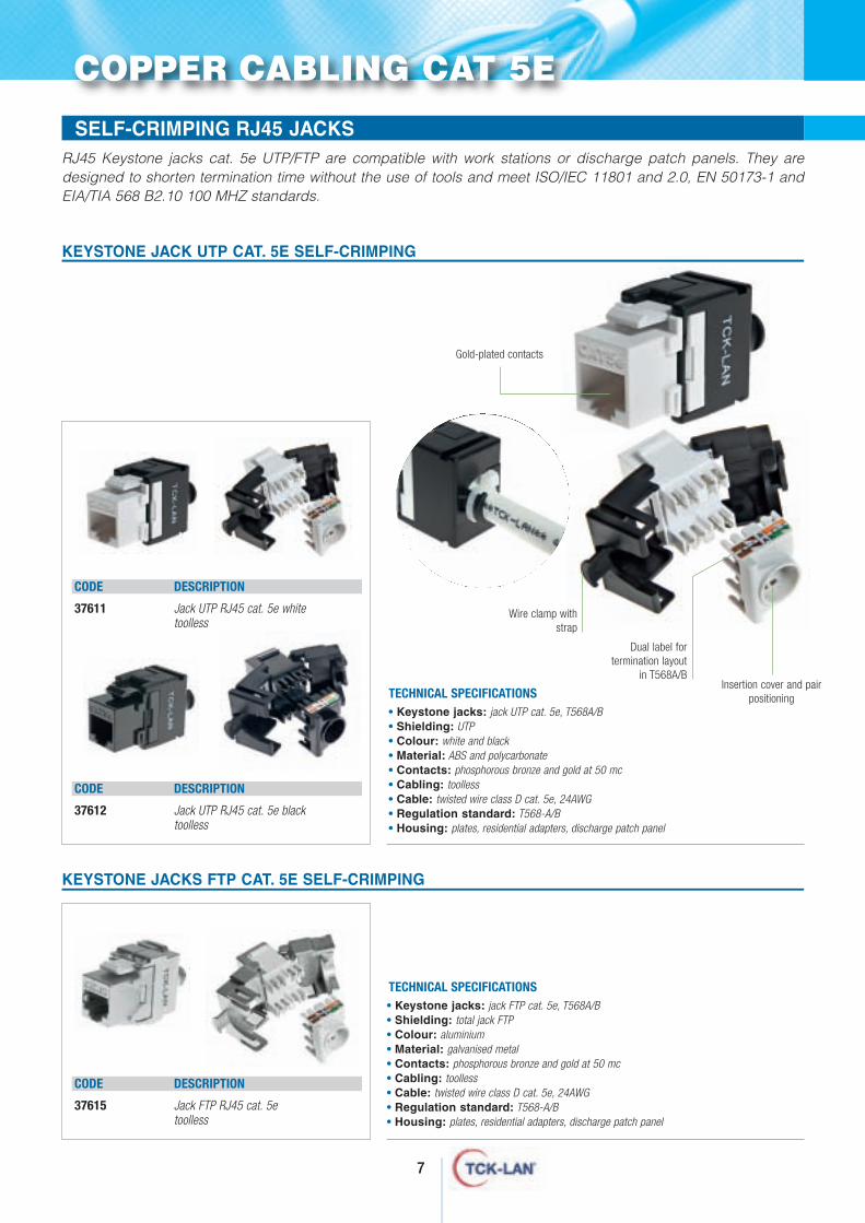
• Keystone jacks: jack UTP cat. 5e, T568A/B • Shielding: UTP• Colour: white and black• Material: ABS and polycarbonate• Contacts: phosphorous bronze and gold at 50 mc• Cabling: toolless • Cable: twisted wire class D cat. 5e, 24AWG• Regulation standard: T568-A/B• Housing: plates, residential adapters, discharge patch panel
TECHNICAL SPECIFICATIONS
• Keystone jacks: jack FTP cat. 5e, T568A/B • Shielding: total jack FTP• Colour: aluminium• Material: galvanised metal• Contacts: phosphorous bronze and gold at 50 mc• Cabling: toolless • Cable: twisted wire class D cat. 5e, 24AWG• Regulation standard: T568-A/B• Housing: plates, residential adapters, discharge patch panel
TECHNICAL SPECIFICATIONS
KEYSTONE JACK UTP CAT. 5E SELF-CRIMPING
KEYSTONE JACKS FTP CAT. 5E SELF-CRIMPING
RJ45 LINE JACKS - Keystone jack UTP cat. 5e system 110SELF-CRIMPING RJ45 JACKSRJ45 Keystone jacks cat. 5e UTP/FTP are compatible with work stations or discharge patch panels. They aredesigned to shorten termination time without the use of tools and meet ISO/IEC 11801 and 2.0, EN 50173-1 andEIA/TIA 568 B2.10 100 MHZ standards.
CODE DESCRIPTION
37615 Jack FTP RJ45 cat. 5etoolless
CODE DESCRIPTION
37611 Jack UTP RJ45 cat. 5e whitetoolless
CODE DESCRIPTION
37612 Jack UTP RJ45 cat. 5e blacktoolless
Dual label fortermination layout
in T568A/B
Wire clamp withstrap
Insertion cover and pairpositioning
Gold-plated contacts
8
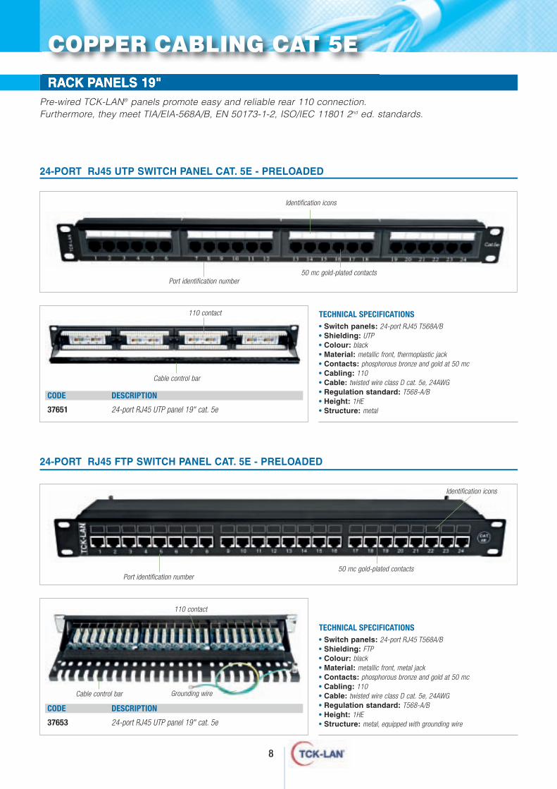
• Switch panels: 24-port RJ45 T568A/B• Shielding: UTP• Colour: black• Material: metallic front, thermoplastic jack• Contacts: phosphorous bronze and gold at 50 mc• Cabling: 110• Cable: twisted wire class D cat. 5e, 24AWG• Regulation standard: T568-A/B• Height: 1HE• Structure: metal
TECHNICAL SPECIFICATIONS
• Switch panels: 24-port RJ45 T568A/B• Shielding: FTP• Colour: black• Material: metallic front, metal jack• Contacts: phosphorous bronze and gold at 50 mc• Cabling: 110• Cable: twisted wire class D cat. 5e, 24AWG• Regulation standard: T568-A/B• Height: 1HE• Structure: metal, equipped with grounding wire
TECHNICAL SPECIFICATIONS
24-PORT RJ45 UTP SWITCH PANEL CAT. 5E - PRELOADED
24-PORT RJ45 FTP SWITCH PANEL CAT. 5E - PRELOADED
CODE DESCRIPTION
37651 24-port RJ45 UTP panel 19" cat. 5e
RACK PANELS 19"Pre-wired TCK-LAN® panels promote easy and reliable rear 110 connection.Furthermore, they meet TIA/EIA-568A/B, EN 50173-1-2, ISO/IEC 11801 2nd ed. standards.
Port identification number
Identification icons
Port identification number50 mc gold-plated contacts
Identification icons
50 mc gold-plated contacts
110 contact
Cable control bar
CODE DESCRIPTION
37653 24-port RJ45 UTP panel 19" cat. 5e
110 contact
Cable control bar
110 contact
Grounding wire
COPPER CABLING CAT 5E
9
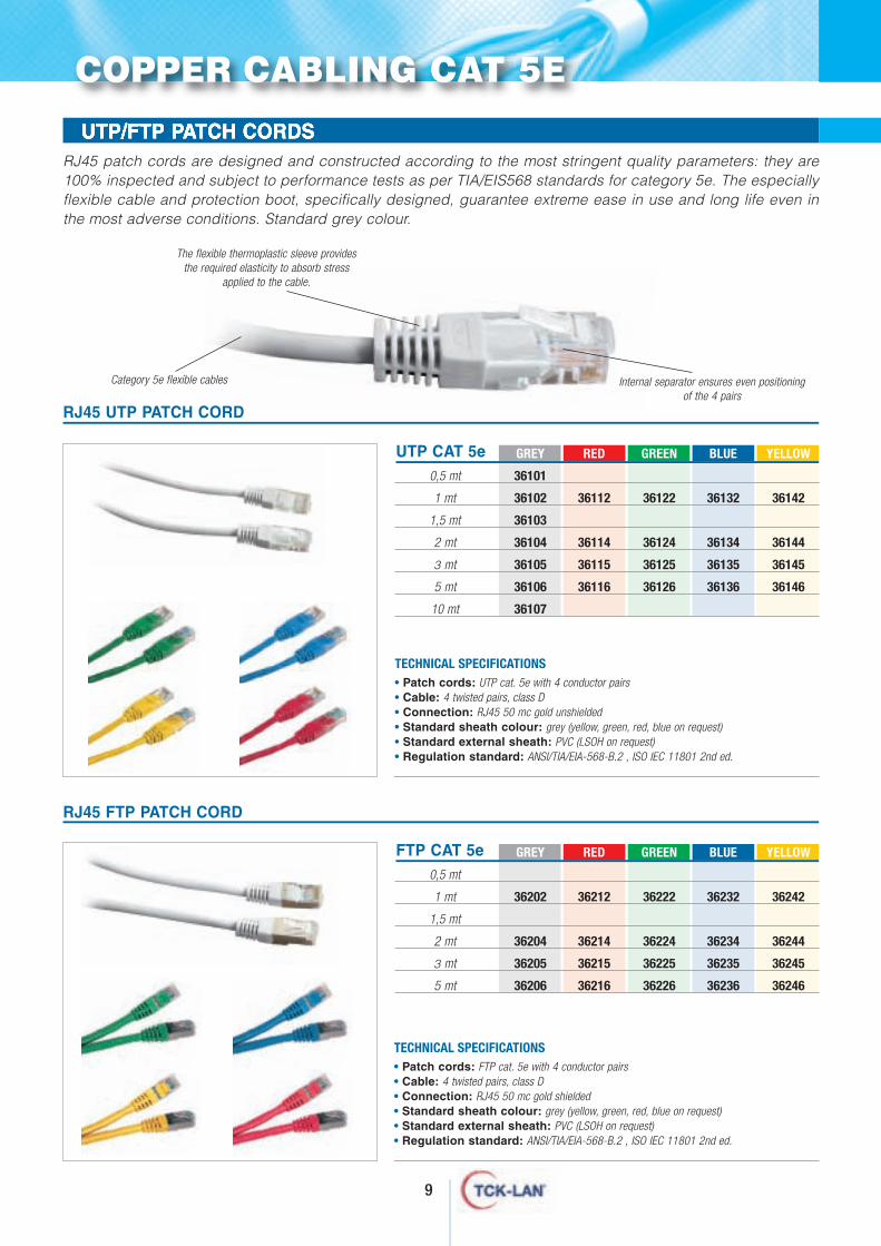
UTP/FTP PATCH CORDS RJ45 patch cords are designed and constructed according to the most stringent quality parameters: they are100% inspected and subject to performance tests as per TIA/EIS568 standards for category 5e. The especiallyflexible cable and protection boot, specifically designed, guarantee extreme ease in use and long life even inthe most adverse conditions. Standard grey colour.
RJ45 UTP PATCH CORD
RJ45 FTP PATCH CORD
The flexible thermoplastic sleeve providesthe required elasticity to absorb stress
applied to the cable.
Category 5e flexible cables Internal separator ensures even positioningof the 4 pairs
COPPER CABLING CAT 5E
UTP CAT 5e GREY RED GREEN BLUE YELLOW
0,5 mt 36101
1 mt 36102 36112 36122 36132 36142
1,5 mt 36103
2 mt 36104 36114 36124 36134 36144
3 mt 36105 36115 36125 36135 36145
5 mt 36106 36116 36126 36136 36146
10 mt 36107
FTP CAT 5e GREY RED GREEN BLUE YELLOW
0,5 mt
1 mt 36202 36212 36222 36232 36242
1,5 mt
2 mt 36204 36214 36224 36234 36244
3 mt 36205 36215 36225 36235 36245
5 mt 36206 36216 36226 36236 36246
• Patch cords: UTP cat. 5e with 4 conductor pairs• Cable: 4 twisted pairs, class D• Connection: RJ45 50 mc gold unshielded• Standard sheath colour: grey (yellow, green, red, blue on request)• Standard external sheath: PVC (LSOH on request)• Regulation standard: ANSI/TIA/EIA-568-B.2 ‚ ISO IEC 11801 2nd ed.
TECHNICAL SPECIFICATIONS
• Patch cords: FTP cat. 5e with 4 conductor pairs• Cable: 4 twisted pairs, class D• Connection: RJ45 50 mc gold shielded• Standard sheath colour: grey (yellow, green, red, blue on request)• Standard external sheath: PVC (LSOH on request)• Regulation standard: ANSI/TIA/EIA-568-B.2 ‚ ISO IEC 11801 2nd ed.
TECHNICAL SPECIFICATIONS

After creating a structured cabling system using TCK-LAN®
brand products only, the certifiedtechnician can send in systemcharacteristics and apply for a25-year warranty.Please note that all cablingcomponents meet internationalRoHS and WEEE environmentalstandards.All current regulations such as TIA/EIA568A/B, ISO 11801,EN50173, IEEE 802.Eab are met.
TCK-LAN® provides networktechnicians with training on
structured cabling systems toguarantee optimal installation
quality. TCK-LAN® coursestrain participants on leading
copper and fibre productapplications.
10
rogramwarranty/certifications
P
opper cabling cat. 6
C
Structured cabling is a group oftransmission components that areinstalled and meet certain specificationsdefined by international standards.TCK-LAN® is a structured cablingcomponent brand: it identifies a widerange of products required to buildcomplete copper systems for LAN andWAN networks and residential cabling.The TCK-LAN® cabling system cat. 6 wasdesigned to easily meet all requirementsset for the most demanding applicationsin accordance with ANSI/TIA/EIA568 B.2-10, ISO/IEC 11801 and EN50173-1standards.25-year warranty on cabling completedand installed by qualified companies
.
12
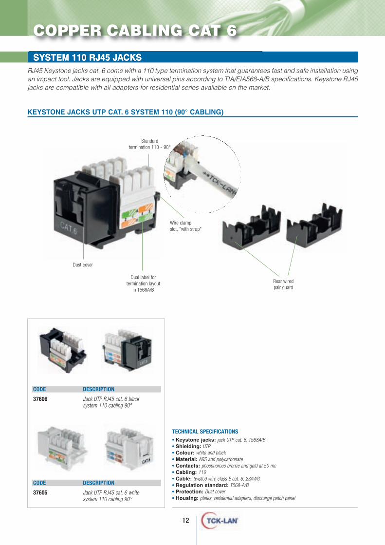
KEYSTONE JACKS UTP CAT. 6 SYSTEM 110 (90° CABLING)
CODE DESCRIPTION
37606 Jack UTP RJ45 cat. 6 blacksystem 110 cabling 90°
CODE DESCRIPTION
37605 Jack UTP RJ45 cat. 6 whitesystem 110 cabling 90°
RJ45 Keystone jacks cat. 6 come with a 110 type termination system that guarantees fast and safe installation usingan impact tool. Jacks are equipped with universal pins according to TIA/EIA568-A/B specifications. Keystone RJ45jacks are compatible with all adapters for residential series available on the market.
SYSTEM 110 RJ45 JACKS
• Keystone jacks: jack UTP cat. 6, T568A/B • Shielding: UTP• Colour: white and black• Material: ABS and polycarbonate• Contacts: phosphorous bronze and gold at 50 mc• Cabling: 110 • Cable: twisted wire class E cat. 6, 23AWG• Regulation standard: T568-A/B• Protection: Dust cover• Housing: plates, residential adapters, discharge patch panel
TECHNICAL SPECIFICATIONS
COPPER CABLING CAT 6
Dust cover
Wire clampslot, "with strap"
Dual label fortermination layout
in T568A/B
Rear wired pair guard
Standardtermination 110 - 90°
13
CODE DESCRIPTION
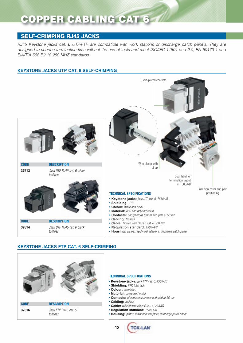
37613 Jack UTP RJ45 cat. 6 whitetoolless
CODE DESCRIPTION
37614 Jack UTP RJ45 cat. 6 blacktoolless
Dual label fortermination layout
in T568A/B
Insertion cover and pairpositioning
• Keystone jacks: jack UTP cat. 6, T568A/B • Shielding: UTP• Colour: white and black• Material: ABS and polycarbonate• Contacts: phosphorous bronze and gold at 50 mc• Cabling: toolless • Cable: twisted wire class E cat. 6, 23AWG• Regulation standard: T568-A/B• Housing: plates, residential adapters, discharge patch panel
TECHNICAL SPECIFICATIONS
KEYSTONE JACKS UTP CAT. 6 SELF-CRIMPING
• Keystone jacks: jack FTP cat. 6, T568A/B • Shielding: FTP, total jack• Colour: aluminium• Material: galvanised metal• Contacts: phosphorous bronze and gold at 50 mc• Cabling: toolless • Cable: twisted wire class E cat. 6, 23AWG• Regulation standard: T568-A/B• Housing: plates, residential adapters, discharge patch panel
TECHNICAL SPECIFICATIONS
KEYSTONE JACKS FTP CAT. 6 SELF-CRIMPING
CODE DESCRIPTION
37616 Jack FTP RJ45 cat. 6toolless
SELF-CRIMPING RJ45 JACKS
COPPER CABLING CAT 6
Wire clamp withstrap
RJ45 Keystone jacks cat. 6 UTP/FTP are compatible with work stations or discharge patch panels. They aredesigned to shorten termination time without the use of tools and meet ISO/IEC 11801 and 2.0, EN 50173-1 andEIA/TIA 568 B2.10 250 MHZ standards.
Gold-plated contacts
14
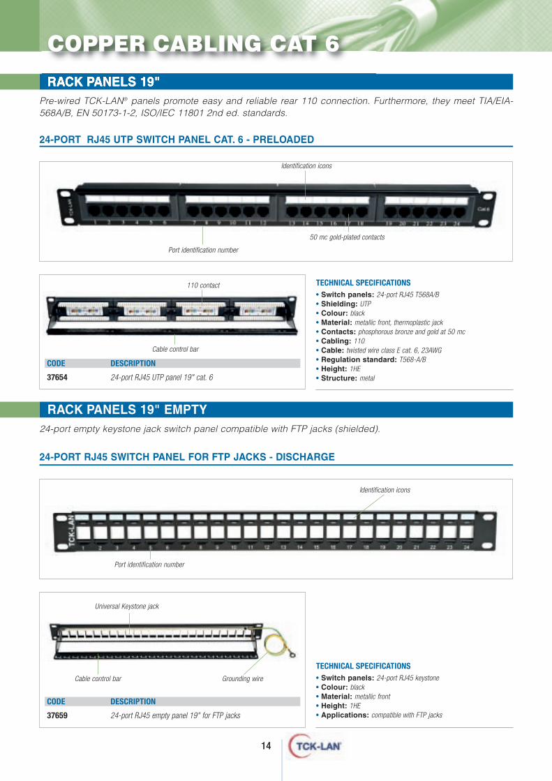
RACK PANELS 19"Pre-wired TCK-LAN® panels promote easy and reliable rear 110 connection. Furthermore, they meet TIA/EIA-568A/B, EN 50173-1-2, ISO/IEC 11801 2nd ed. standards.
• Switch panels: 24-port RJ45 T568A/B• Shielding: UTP• Colour: black• Material: metallic front, thermoplastic jack• Contacts: phosphorous bronze and gold at 50 mc• Cabling: 110• Cable: twisted wire class E cat. 6, 23AWG• Regulation standard: T568-A/B• Height: 1HE• Structure: metal
TECHNICAL SPECIFICATIONS
24-PORT RJ45 UTP SWITCH PANEL CAT. 6 - PRELOADED
CODE DESCRIPTION
37654 24-port RJ45 UTP panel 19" cat. 6
Port identification number
Identification icons
50 mc gold-plated contacts
110 contact
Cable control bar
• Switch panels: 24-port RJ45 keystone• Colour: black• Material: metallic front• Height: 1HE• Applications: compatible with FTP jacks
TECHNICAL SPECIFICATIONS
24-PORT RJ45 SWITCH PANEL FOR FTP JACKS - DISCHARGE
Port identification number
Identification icons
CODE DESCRIPTION
37659 24-port RJ45 empty panel 19" for FTP jacks
Grounding wireCable control bar
Universal Keystone jack
RACK PANELS 19" EMPTY24-port empty keystone jack switch panel compatible with FTP jacks (shielded).
COPPER CABLING CAT 6
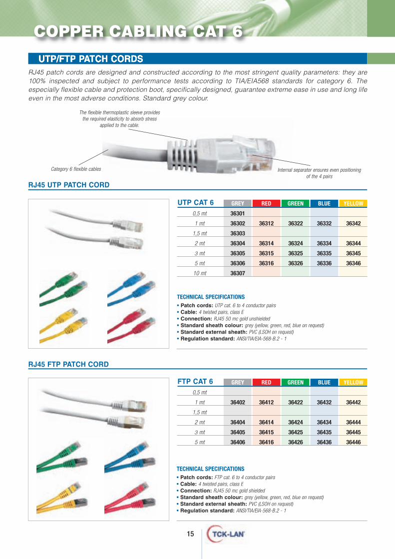
The flexible thermoplastic sleeve providesthe required elasticity to absorb stress
applied to the cable.
Category 6 flexible cables Internal separator ensures even positioningof the 4 pairs
15
UTP/FTP PATCH CORDSRJ45 patch cords are designed and constructed according to the most stringent quality parameters: they are100% inspected and subject to performance tests according to TIA/EIA568 standards for category 6. Theespecially flexible cable and protection boot, specifically designed, guarantee extreme ease in use and long lifeeven in the most adverse conditions. Standard grey colour.
RJ45 UTP PATCH CORD
RJ45 FTP PATCH CORD
COPPER CABLING CAT 6
UTP CAT 6 GREY RED GREEN BLUE YELLOW
0,5 mt 36301
1 mt 36302 36312 36322 36332 36342
1,5 mt 36303
2 mt 36304 36314 36324 36334 36344
3 mt 36305 36315 36325 36335 36345
5 mt 36306 36316 36326 36336 36346
10 mt 36307
FTP CAT 6 GREY RED GREEN BLUE YELLOW
0,5 mt
1 mt 36402 36412 36422 36432 36442
1,5 mt
2 mt 36404 36414 36424 36434 36444
3 mt 36405 36415 36425 36435 36445
5 mt 36406 36416 36426 36436 36446
• Patch cords: UTP cat. 6 to 4 conductor pairs• Cable: 4 twisted pairs, class E• Connection: RJ45 50 mc gold unshielded• Standard sheath colour: grey (yellow, green, red, blue on request)• Standard external sheath: PVC (LSOH on request)• Regulation standard: ANSI/TIA/EIA-568-B.2 - 1
TECHNICAL SPECIFICATIONS
• Patch cords: FTP cat. 6 to 4 conductor pairs• Cable: 4 twisted pairs, class E• Connection: RJ45 50 mc gold shielded• Standard sheath colour: grey (yellow, green, red, blue on request)• Standard external sheath: PVC (LSOH on request)• Regulation standard: ANSI/TIA/EIA-568-B.2 - 1
TECHNICAL SPECIFICATIONS
After creating a structured cabling system using TCK-LAN®
brand products only, the certifiedtechnician can send in systemcharacteristics and apply for a25-year warranty.Please note that all cablingcomponents meet internationalRoHS and WEEE environmentalstandards.All current regulations such as TIA/EIA568A/B, ISO 11801,EN50173, IEEE 802.Eab are met.
TCK-LAN® provides networktechnicians with training on
structured cabling systems toguarantee optimal installation
quality. TCK-LAN® coursestrain participants on leading
copper and fibre productapplications.
16
rogramwarranty/certifications
P
opper cabling cat. 6A
C
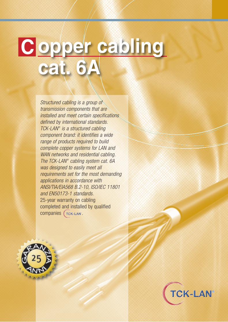
Structured cabling is a group of transmission components that areinstalled and meet certain specificationsdefined by international standards.TCK-LAN® is a structured cabling component brand: it identifies a widerange of products required to buildcomplete copper systems for LAN andWAN networks and residential cabling.The TCK-LAN® cabling system cat. 6A was designed to easily meet allrequirements set for the most demandingapplications in accordance withANSI/TIA/EIA568 B.2-10, ISO/IEC 11801and EN50173-1 standards.25-year warranty on cabling completed and installed by qualifiedcompanies .
CODE DESCRIPTION
37618 Pass through jackRJ45/RJ45 cat. 6a
18
RJ45 LINE JACKS - Keystone jack UTP cat. 5e system 110SELF-CRIMPING RJ45 JACKS
RJ45 LINE JACKS - Keystone jack UTP cat. 5e system 110PASS THROUGH KEYSTONE RJ45/RJ45 CAT. 6A
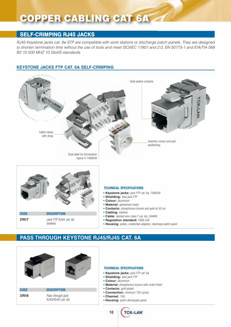
RJ45 Keystone jacks cat. 6e STP are compatible with work stations or discharge patch panels. They are designedto shorten termination time without the use of tools and meet ISO/IEC 11801 and 2.0, EN 50173-1 and EIA/TIA 568B2.10 500 MHZ 10 Gbit/S standards.
• Keystone jacks: jack FTP cat. 6a, T568A/B • Shielding: total jack FTP• Colour: aluminium• Material: galvanised metal• Contacts: phosphorous bronze and gold at 50 mc• Cabling: toolless • Cable: twisted wire class F cat. 6a, 24AWG• Regulation standard: T568-A/B• Housing: plates, residential adapters, discharge patch panel
TECHNICAL SPECIFICATIONS
KEYSTONE JACKS FTP CAT. 6A SELF-CRIMPING
Dual label for termination layout in T568A/B
Insertion covers and pairpositioning
Cable clampwith strap
Gold-plated contacts
CODE DESCRIPTION
37617 Jack FTP RJ45 cat. 6atoolless
COPPER CABLING CAT 6A
• Keystone jacks: jack FTP cat. 6a• Shielding: total jack FTP• Colour: aluminium• Material: phosphorous bronze with nickel finish• Contacts: gold plated• Connection: minimum 750 cycles • Channel: 10G• Housing: patch discharges panel
TECHNICAL SPECIFICATIONS
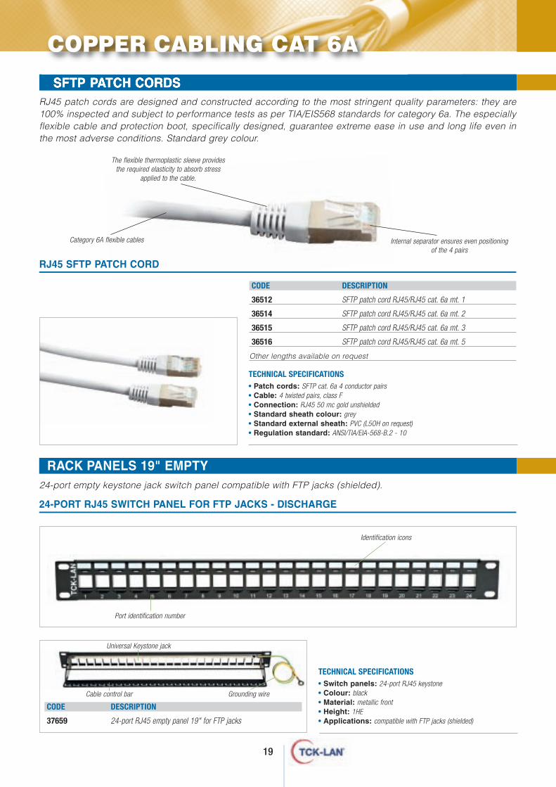
The flexible thermoplastic sleeve providesthe required elasticity to absorb stress
applied to the cable.
Category 6A flexible cables Internal separator ensures even positioningof the 4 pairs
19
WALL RACKS - RACKS 10 " AND ACCESSORIES
RACK PANELS 19" EMPTY24-port empty keystone jack switch panel compatible with FTP jacks (shielded).
SFTP PATCH CORDS RJ45 patch cords are designed and constructed according to the most stringent quality parameters: they are100% inspected and subject to performance tests as per TIA/EIS568 standards for category 6a. The especiallyflexible cable and protection boot, specifically designed, guarantee extreme ease in use and long life even inthe most adverse conditions. Standard grey colour.
CODE DESCRIPTION
36512 SFTP patch cord RJ45/RJ45 cat. 6a mt. 1
36514 SFTP patch cord RJ45/RJ45 cat. 6a mt. 2
36515 SFTP patch cord RJ45/RJ45 cat. 6a mt. 3
36516 SFTP patch cord RJ45/RJ45 cat. 6a mt. 5
Other lengths available on request
• Patch cords: SFTP cat. 6a 4 conductor pairs• Cable: 4 twisted pairs, class F• Connection: RJ45 50 mc gold unshielded• Standard sheath colour: grey• Standard external sheath: PVC (L5OH on request)• Regulation standard: ANSI/TIA/EIA-568-B.2 - 10
TECHNICAL SPECIFICATIONS
RJ45 SFTP PATCH CORD
• Switch panels: 24-port RJ45 keystone• Colour: black• Material: metallic front• Height: 1HE• Applications: compatible with FTP jacks (shielded)
TECHNICAL SPECIFICATIONS
24-PORT RJ45 SWITCH PANEL FOR FTP JACKS - DISCHARGE
Port identification number
Identification icons
CODE DESCRIPTION
37659 24-port RJ45 empty panel 19" for FTP jacks
Grounding wire
COPPER CABLING CAT 6A
Cable control bar
Universal Keystone jack
20
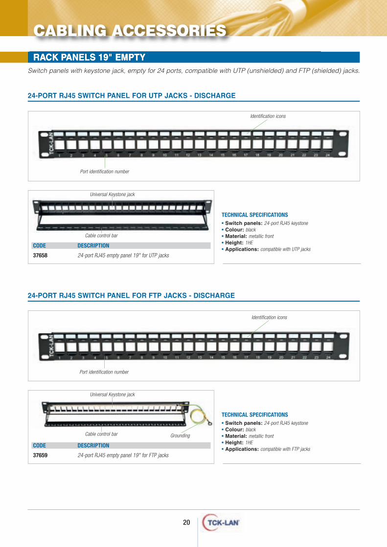
RACK PANELS 19" EMPTYSwitch panels with keystone jack, empty for 24 ports, compatible with UTP (unshielded) and FTP (shielded) jacks.
• Switch panels: 24-port RJ45 keystone• Colour: black• Material: metallic front• Height: 1HE• Applications: compatible with UTP jacks
TECHNICAL SPECIFICATIONS
24-PORT RJ45 SWITCH PANEL FOR UTP JACKS - DISCHARGE
Port identification number
Identification icons
CODE DESCRIPTION
37658 24-port RJ45 empty panel 19" for UTP jacks
• Switch panels: 24-port RJ45 keystone• Colour: black• Material: metallic front• Height: 1HE• Applications: compatible with FTP jacks
TECHNICAL SPECIFICATIONS
24-PORT RJ45 SWITCH PANEL FOR FTP JACKS - DISCHARGE
Port identification number
Identification icons
CODE DESCRIPTION
37659 24-port RJ45 empty panel 19" for FTP jacks
Grounding
CABLING ACCESSORIES
Cable control bar
Universal Keystone jack
Cable control bar
Universal Keystone jack
21
CODE DESCRIPTION
37631 Bticino magic white adapter
37632 Bticino living international black adapter
37633 Bticino living black adapter
37634 Bticino living light white adapter
37635 Bticino living magic TT white adapter
37637 Bticino living light tech silver adapter
37636 Bticino matix white adapter
37638 Bticino axolute silver adapter
37647 Bticino axolute black adapter
37639 Vimar idea white adapter
37640 Vimar idea black adapter
37641 Vimar plana white adapter
37642 Vimar eikon black adapter
37646 Vimar eikon silver adapter
37643 Gewiss playbuss black adapter
37644 Gewiss system 20 white adapter
37645 Gewiss system 20 black adapter
34649 Gewiss chorus black adapter
37648 Gewiss chorus white adapter
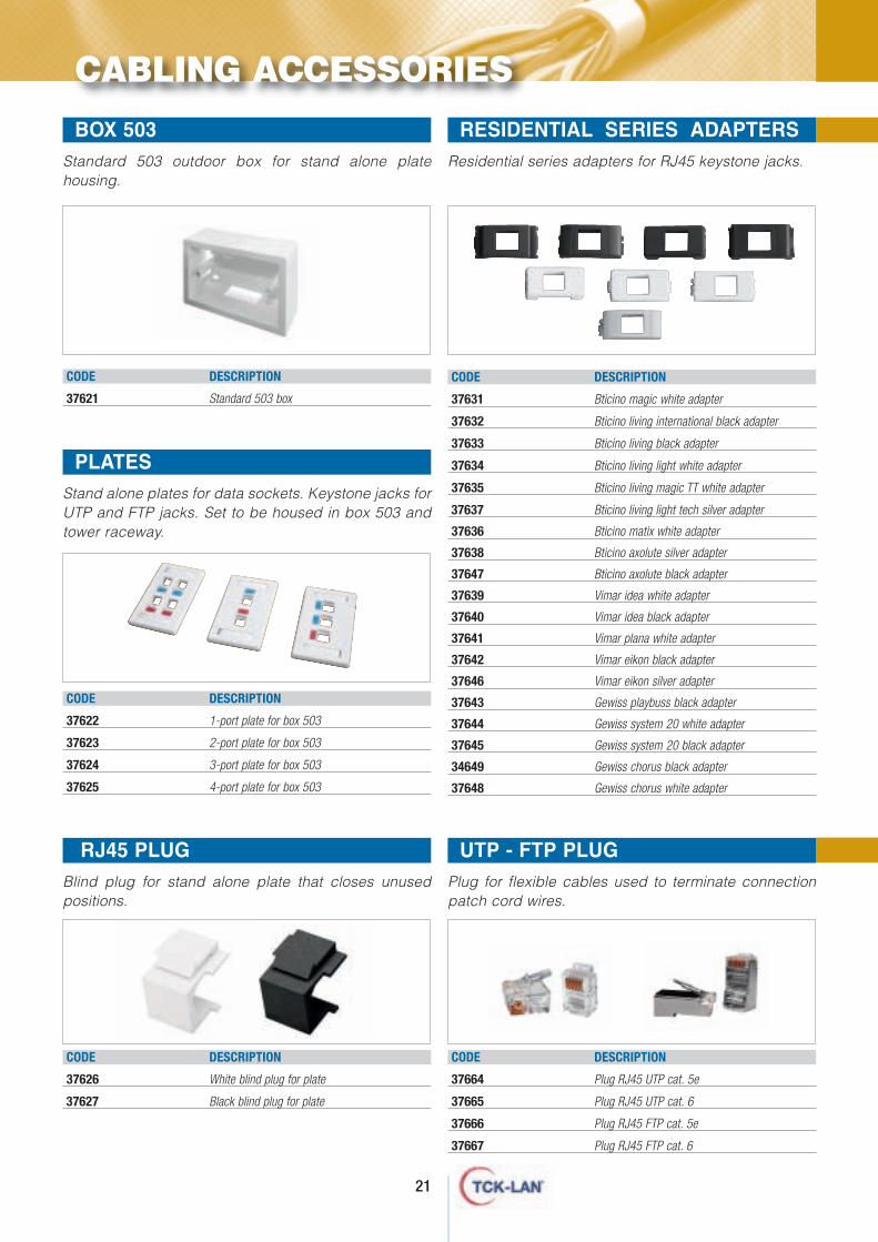
Residential series adapters for RJ45 keystone jacks.
CABLING ACCESSORIES
Standard 503 outdoor box for stand alone platehousing.
CODE DESCRIPTION
37621 Standard 503 box
BOX 503 RESIDENTIAL SERIES ADAPTERS
Stand alone plates for data sockets. Keystone jacks forUTP and FTP jacks. Set to be housed in box 503 andtower raceway.
CODE DESCRIPTION
37622 1-port plate for box 503
37623 2-port plate for box 503
37624 3-port plate for box 503
37625 4-port plate for box 503
PLATES
RJ45 PLUGBlind plug for stand alone plate that closes unusedpositions.
CODE DESCRIPTION
37626 White blind plug for plate
37627 Black blind plug for plate
UTP - FTP PLUG Plug for flexible cables used to terminate connectionpatch cord wires.
CODE DESCRIPTION
37664 Plug RJ45 UTP cat. 5e
37665 Plug RJ45 UTP cat. 6
37666 Plug RJ45 FTP cat. 5e
37667 Plug RJ45 FTP cat. 6
CODE DESCRIPTION
37691 Wire pair continuity tester
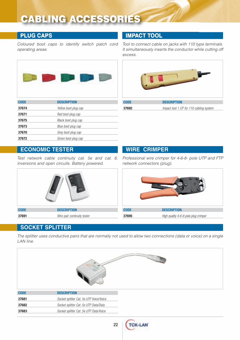
Coloured boot caps to identify switch patch cordoperating areas.
Tool to connect cable on jacks with 110 type terminals.It simultaneously inserts the conductor while cutting offexcess.
CODE DESCRIPTION
37692 Impact tool 1 CP for 110 cabling system
PLUG CAPS IMPACT TOOL
ECONOMIC TESTERTest network cable continuity cat. 5e and cat. 6,inversions and open circuits. Battery powered.
CODE DESCRIPTION
37681 Socket splitter Cat. 5e UTP Voice/Voice
37682 Socket splitter Cat. 5e UTP Data/Data
37683 Socket splitter Cat. 5e UTP Data/Voice
SOCKET SPLITTERThe splitter uses conductive pairs that are normally not used to allow two connections (data or voice) on a singleLAN line.
CODE DESCRIPTION
37674 Yellow boot plug cap
37671 Red boot plug cap
37675 Black boot plug cap
37673 Blue boot plug cap
37670 Grey boot plug cap
37672 Green boot plug cap
CODE DESCRIPTION
37695 High quality 4-6-8 pole plug crimper
WIRE CRIMPERProfessional wire crimper for 4-6-8- pole UTP and FTPnetwork connectors (plug).
22
CABLING ACCESSORIES
elephone cabling cat. 3
T
Structured cabling is a group oftransmission components that areinstalled and meet certain specificationsdefined by international standards.TCK-LAN® is a structured cabling component brand that identifies a widerange of products required to buildcomplete copper systems for LAN andWAN networks and residential cabling.The TCK-LAN® cabling system cat. 3 wasdesigned to transmit digital (ISDN) andanalogue voice signals. Ideal for allEN50173-1 and ISO-IEC 11801 standardclass C applications.
24
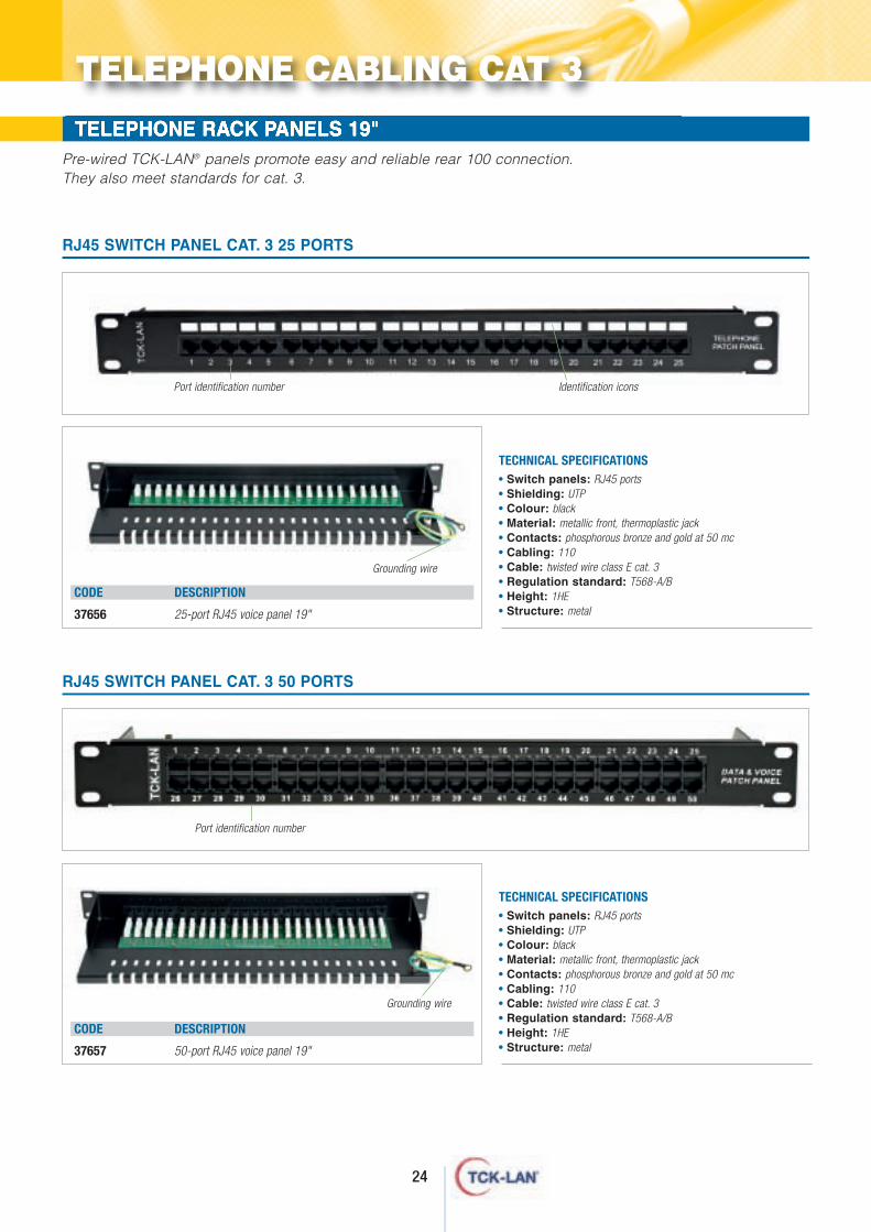
TELEPHONE RACK PANELS 19"Pre-wired TCK-LAN® panels promote easy and reliable rear 100 connection.They also meet standards for cat. 3.
• Switch panels: RJ45 ports • Shielding: UTP• Colour: black• Material: metallic front, thermoplastic jack• Contacts: phosphorous bronze and gold at 50 mc• Cabling: 110• Cable: twisted wire class E cat. 3• Regulation standard: T568-A/B• Height: 1HE• Structure: metal
TECHNICAL SPECIFICATIONS
RJ45 SWITCH PANEL CAT. 3 25 PORTS
Port identification number Identification icons
CODE DESCRIPTION
37656 25-port RJ45 voice panel 19"
Grounding wire
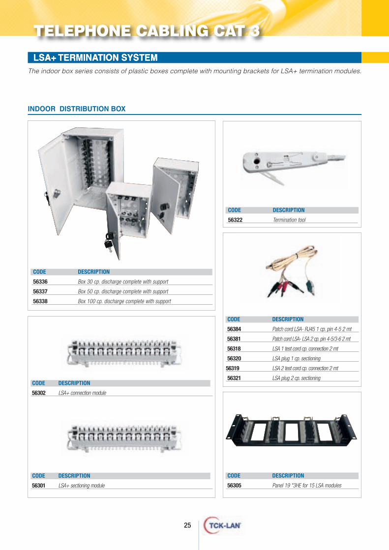
• Switch panels: RJ45 ports • Shielding: UTP• Colour: black• Material: metallic front, thermoplastic jack• Contacts: phosphorous bronze and gold at 50 mc• Cabling: 110• Cable: twisted wire class E cat. 3• Regulation standard: T568-A/B• Height: 1HE• Structure: metal
TECHNICAL SPECIFICATIONS
RJ45 SWITCH PANEL CAT. 3 50 PORTS
Port identification number
CODE DESCRIPTION
37657 50-port RJ45 voice panel 19"
TELEPHONE CABLING CAT 3
Grounding wire
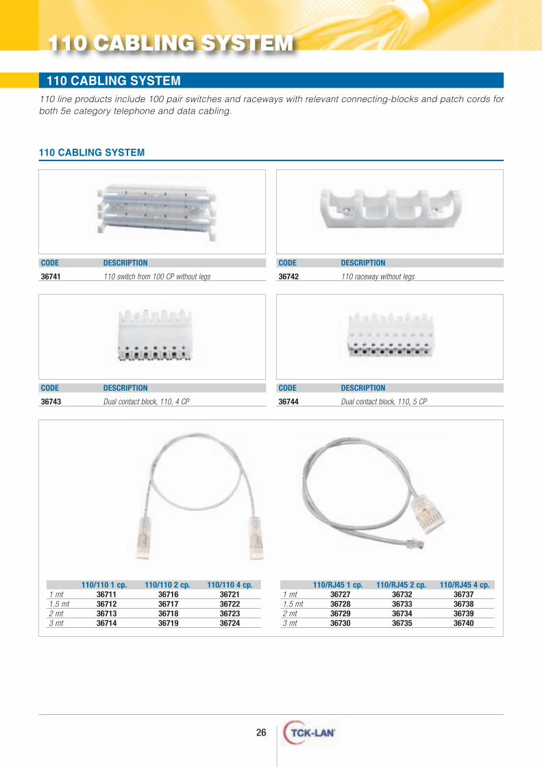
LSA+ TERMINATION SYSTEMThe indoor box series consists of plastic boxes complete with mounting brackets for LSA+ termination modules.
INDOOR DISTRIBUTION BOX
CODE DESCRIPTION
56336 Box 30 cp. discharge complete with support
56337 Box 50 cp. discharge complete with support
56338 Box 100 cp. discharge complete with support
CODE DESCRIPTION
56302 LSA+ connection module
CODE DESCRIPTION
56301 LSA+ sectioning module
CODE DESCRIPTION
56322 Termination tool
CODE DESCRIPTION
56384 Patch cord LSA- RJ45 1 cp. pin 4-5 2 mt
56381 Patch cord LSA- LSA 2 cp. pin 4-5/3-6 2 mt
56318 LSA 1 test cord cp. connection 2 mt
56320 LSA plug 1 cp. sectioning
56319 LSA 2 test cord cp. connection 2 mt
56321 LSA plug 2 cp. sectioning
CODE DESCRIPTION
56305 Panel 19 "3HE for 15 LSA modules
25
TELEPHONE CABLING CAT 3
26
110 CABLING SYSTEM
110 line products include 100 pair switches and raceways with relevant connecting-blocks and patch cords forboth 5e category telephone and data cabling.
110 CABLING SYSTEM
110 CABLING SYSTEM
CODE DESCRIPTION
36741 110 switch from 100 CP without legs
CODE DESCRIPTION
36742 110 raceway without legs
CODE DESCRIPTION
36743 Dual contact block, 110, 4 CP
CODE DESCRIPTION
36744 Dual contact block, 110, 5 CP
110/110 1 cp. 110/110 2 cp. 110/110 4 cp.1 mt1.5 mt2 mt3 mt
36711 36716 3672136712 36717 3672236713 36718 3672336714 36719 36724
110/RJ45 1 cp. 110/RJ45 2 cp. 110/RJ45 4 cp.1 mt1.5 mt2 mt3 mt
36727 36732 3673736728 36733 3673836729 36734 3673936730 36735 36740
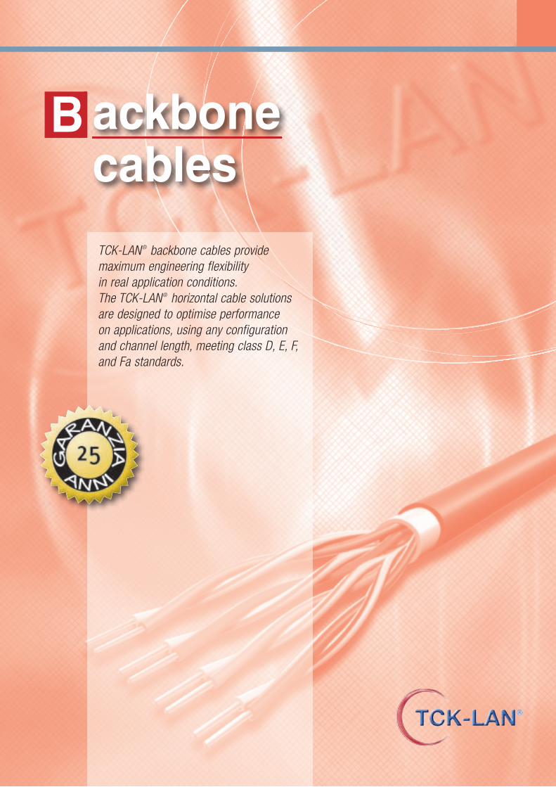
ackbone cables
B
TCK-LAN® backbone cables providemaximum engineering flexibility in real application conditions. The TCK-LAN® horizontal cable solutionsare designed to optimise performance on applications, using any configurationand channel length, meeting class D, E, F,and Fa standards.
FLOOR RACKS - 600x600 - 600x800 - 800x600 - 800x800U/UTP HORIZONTAL CABLES - 100 OHMS - 200 MHZ
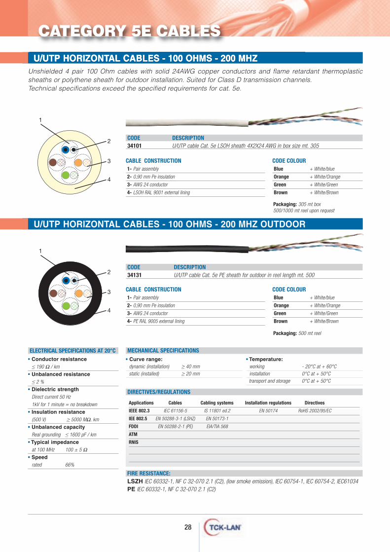
CABLE CONSTRUCTION1- Pair assembly
2- 0,90 mm Pe insulation
3- AWG 24 conductor
4- LSOH RAL 9001 external lining
CODE DESCRIPTION34101 U/UTP cable Cat. 5e LSOH sheath 4X2X24 AWG in box size mt. 305
CODE COLOURBlue + White/blue
Orange + White/Orange
Green + White/Green
Brown + White/Brown
Packaging: 305 mt box500/1000 mt reel upon request
Packaging: 500 mt reel
Unshielded 4 pair 100 Ohm cables with solid 24AWG copper conductors and flame retardant thermoplasticsheaths or polythene sheath for outdoor installation. Suited for Class D transmission channels. Technical specifications exceed the specified requirements for cat. 5e.
CODE DESCRIPTION34131 U/UTP cable Cat. 5e PE sheath for outdoor in reel length mt. 500
CODE COLOURBlue + White/blue
Orange + White/Orange
Green + White/Green
Brown + White/Brown
FLOOR RACKS - 600x600 - 600x800 - 800x600 - 800x800U/UTP HORIZONTAL CABLES - 100 OHMS - 200 MHZ OUTDOOR
CABLE CONSTRUCTION1- Pair assembly
2- 0,90 mm Pe insulation
3- AWG 24 conductor
4- PE RAL 9005 external lining
• Curve range:dynamic (installation) ≥ 40 mmstatic (installed) ≥ 20 mm
• Temperature:working - 20°C at + 60°Cinstallation 0°C at + 50°Ctransport and storage 0°C at + 50°C
MECHANICAL SPECIFICATIONS
FIRE RESISTANCE:LSZH IEC 60332-1, NF C 32-070 2.1 (C2), (low smoke emission), IEC 60754-1, IEC 60754-2, IEC61034PE IEC 60332-1, NF C 32-070 2.1 (C2)
Applications Cables Cabling systems Installation regulations Directives
IEEE 802.3 IEC 61156-5 IS 11801 ed.2 EN 50174 RoHS 2002/95/EC
IEE 802.5 EN 50288-3-1 (LSHZ) EN 50173-1
FDDI EN 50288-2-1 (PE) EIA/TIA 568
ATM
RNIS
DIRECTIVES/REGULATIONS
ELECTRICAL SPECIFICATIONS AT 20°C• Conductor resistance
≤ 190 Ω / km
• Unbalanced resistance≤ 2 %
• Dielectric strengthDirect current 50 Hz
1kV for 1 minute = no breakdown
• Insulation resistance(500 V) ≥ 5000 MΩ. km
• Unbalanced capacityReal grounding ≤ 1600 pF / km
• Typical impedanceat 100 MHz 100 ± 5 Ω
• Speedrated 66%
1
2
3
4
1
2
3
4
CATEGORY 5E CABLES
28
29
FLOOR RACKS - 600x600 - 600x800 - 800x600 - 800x800F/UTP - SF/UTP HORIZONTAL CABLES - 100 OHMS - 200 MHZ
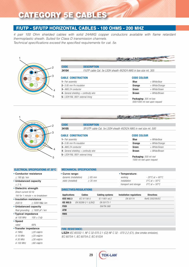
CABLE CONSTRUCTION1- Pair assembly
2- 0.95 mm Pe insulation
3- AWG 24 conductor
4- General shielding + continuity wire
5- LSOH RAL 9001 external lining
CODE DESCRIPTION34104 F/UTP cable Cat. 5e LSOH sheath 4X2X24 AWG in box size mt. 305
CODE COLOURBlue + White/blue
Orange + White/Orange
Green + White/Green
Brown + White/Brown
1
4 pair 100 Ohm shielded cables with solid 24AWG copper conductors available with flame retardantthermoplastic sheath. Suited for Class D transmission channels. Technical specifications exceed the specified requirements for cat. 5e.
CODE DESCRIPTION34105 SF/UTP cable Cat. 5e LSOH sheath 4X2X24 AWG in reel size mt. 500
CODE COLOURBlue + White/blue
Orange + White/Orange
Green + White/Green
Brown + White/Brown
CABLE CONSTRUCTION1- Pair assembly
2- 0.95 mm Pe insulation
3- AWG 24 conductor
4- General shielding + continuity wire
5- LSOH RAL 9001 external lining
• Curve range:dynamic (installation) ≥ 65 mmstatic (installed) ≥ 35 mm
• Temperature:working - 20°C at + 60°Cinstallation 0°C at + 50°Ctransport and storage 0°C at + 50°C
MECHANICAL SPECIFICATIONS
FIRE RESISTANCE:LSZH IEC 60332-1, NF C 32-070 2.1 (C2) NF C 32 - 070 2.2 (C1), (low smoke emission), IEC 60754-1, IEC 60754-2, IEC 61034
Applications Cables Cabling systems Installation regulations Directives
IEEE 802.3 IEC 61156-5 IS 11801 ed.2 EN 50174 RoHS 2002/95/EC
IEE 802.5 EN 50288-2-1 (LSHZ) EN 50173-1
FDDI EIA/TIA 568
ATM
RNIS
DIRECTIVES/REGULATIONS
ELECTRICAL SPECIFICATIONS AT 20°C• Conductor resistance
≤ 190 Ω / km
• Unbalanced capacity≤ 2 %
• Dielectric strengthDirect current 50 Hz
1kV for 1 minute = no breakdown
• Insulation resistance(500 V) ≥ 5000 MΩ. km
• Unbalanced capacityReal grounding ≤ 1600 pF / km
• Typical impedanceat 100 MHz 100 ± 5 Ω
• Speedrated 66%
• Transfer impedanceA 1MHz ≤20 mΩ/m
A 10 MHz ≤20 mΩ/m
A 30 MHz ≤30 mΩ/m
A 100 MHz ≤60 mΩ/m
Packaging: 305 mt box500/1000 mt reel upon request
Packaging: 500 mt reel1000 mt reel upon request
1
3
2
2
3
4
5
4
5
CATEGORY 5E CABLES
30
FLOOR RACKS - 600x600 - 600x800 - 800x600 - 800x800U/UTP HORIZONTAL CABLES - 100 OHMS - 450 MHZ
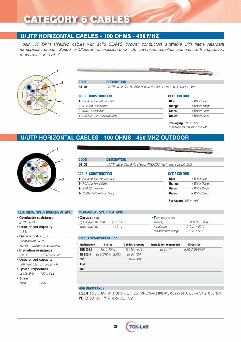
CABLE CONSTRUCTION1- Pair assembly with separator
2- 0.98 mm Pe insulation
3- AWG 23 conductor
4- LSOH RAL 9001 external lining
• Curve range:dynamic (installation) ≥ 50 mmstatic (installed) ≥ 25 mm
• Temperature:working - 20°C at + 60°Cinstallation 0°C at + 50°Ctransport and storage 0°C at + 50°C
MECHANICAL SPECIFICATIONS
FIRE RESISTANCE:LSZH IEC 60332-1, NF C 32-070 2.1 (C2), (low smoke emission), IEC 60754-1, IEC 60754-2, IEC61034PE IEC 60332-1, NF C 32-070 2.1 (C2)
• Conductor resistance≤ 190 Ω / km
• Unbalanced capacity≤ 2 %
• Dielectric strengthDirect current 50 Hz
1kV for 1 minute = no breakdown
• Insulation resistance(500 V) ≥ 5000 MΩ. km
• Unbalanced capacityReal grounding ≤ 1600 pF / km
• Typical impedanceat 100 MHz 100 ± 5 Ω
• Speedrated 66%
CODE DESCRIPTION34106 U/UTP cable Cat. 6 LSOH sheath 4X2X23 AWG in box size mt. 305
Applications Cables Cabling systems Installation regulations Directives
IEEE 802.3 IEC 61156-5 IS 11801 ed.2 EN 50174 RoHS 2002/95/EC
IEE 802.5 EN 50288-6-1 (LSHZ) EN 50173-1
FDDI EIA/TIA 568
ATM
RNIS
DIRECTIVES/REGULATIONS
CODE COLOURBlue + White/blue
Orange + White/Orange
Green + White/Green
Brown + White/Brown
1
2
4
4 pair 100 Ohm shielded cables with solid 23AWG copper conductors available with flame retardantthermoplastic sheath. Suited for Class E transmission channels. Technical specifications exceed the specifiedrequirements for cat. 6.
ELECTRICAL SPECIFICATIONS AT 20°C
3
Packaging: 305 mt box500/1000 mt reel upon request
CABLE CONSTRUCTION1- Pair assembly with separator
2- 0.98 mm Pe insulation
3- AWG 23 conductor
4- PE RAL 9005 external lining
CODE DESCRIPTION34132 U/UTP cable Cat. 6 PE sheath 4X2X23 AWG in reel size mt. 305
CODE COLOURBlue + White/blue
Orange + White/Orange
Green + White/Green
Brown + White/Brown
1
2
4
3
Packaging: 305 mt reel
CATEGORY 6 CABLES
FLOOR RACKS - 600x600 - 600x800 - 800x600 - 800x800U/UTP HORIZONTAL CABLES - 100 OHMS - 450 MHZ OUTDOOR
31
FLOOR RACKS - 600x600 - 600x800 - 800x600 - 800x800F/UTP - SF/UTP HORIZONTAL CABLES - 100 OHMS - 450 MHZ
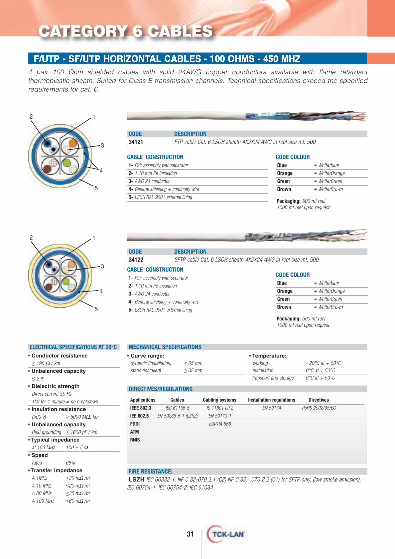
CABLE CONSTRUCTION1- Pair assembly with separator
2- 1.10 mm Pe insulation
3- AWG 24 conductor
4- General shielding + continuity wire
5- LSOH RAL 9001 external lining
• Curve range:dynamic (installation) ≥ 65 mmstatic (installed) ≥ 35 mm
• Temperature:working - 20°C at + 60°Cinstallation 0°C at + 50°Ctransport and storage 0°C at + 50°C
MECHANICAL SPECIFICATIONS
FIRE RESISTANCE:LSZH IEC 60332-1, NF C 32-070 2.1 (C2) NF C 32 - 070 2.2 (C1) for SFTP only, (low smoke emission),
IEC 60754-1, IEC 60754-2, IEC 61034
CODE DESCRIPTION34121 FTP cable Cat. 6 LSOH sheath 4X2X24 AWG in reel size mt. 500
Applications Cables Cabling systems Installation regulations Directives
IEEE 802.3 IEC 61156-5 IS 11801 ed.2 EN 50174 RoHS 2002/95/EC
IEE 802.5 EN 50288-5-1 (LSHZ) EN 50173-1
FDDI EIA/TIA 568
ATM
RNIS
DIRECTIVES/REGULATIONS
CODE COLOURBlue + White/blue
Orange + White/Orange
Green + White/Green
Brown + White/Brown
12
5
4 pair 100 Ohm shielded cables with solid 24AWG copper conductors available with flame retardantthermoplastic sheath. Suited for Class E transmission channels. Technical specifications exceed the specifiedrequirements for cat. 6.
CODE DESCRIPTION34122 SFTP cable Cat. 6 LSOH sheath 4X2X24 AWG in reel size mt. 500
CODE COLOURBlue + White/blue
Orange + White/Orange
Green + White/Green
Brown + White/Brown
ELECTRICAL SPECIFICATIONS AT 20°C
3
4
CABLE CONSTRUCTION1- Pair assembly with separator
2- 1.10 mm Pe insulation
3- AWG 24 conductor
4- General shielding + continuity wire
5- LSOH RAL 9001 external lining
12
5
3
4
• Conductor resistance≤ 190 Ω / km
• Unbalanced capacity≤ 2 %
• Dielectric strengthDirect current 50 Hz
1kV for 1 minute = no breakdown
• Insulation resistance(500 V) ≥ 5000 MΩ. km
• Unbalanced capacityReal grounding ≤ 1600 pF / km
• Typical impedanceat 100 MHz 100 ± 5 Ω
• Speedrated 66%
• Transfer impedanceA 1MHz ≤20 mΩ/m
A 10 MHz ≤20 mΩ/m
A 30 MHz ≤30 mΩ/m
A 100 MHz ≤60 mΩ/m
Packaging: 500 mt reel1000 mt reel upon request
Packaging: 500 mt reel1000 mt reel upon request
CATEGORY 6 CABLES
32
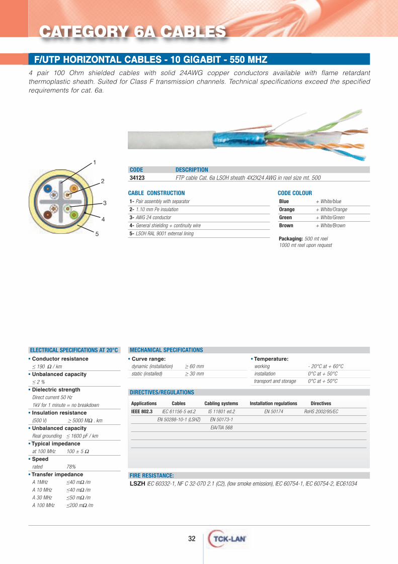
FLOOR RACKS - 600x600 - 600x800 - 800x600 - 800x800F/UTP HORIZONTAL CABLES - 10 GIGABIT - 550 MHZ
CABLE CONSTRUCTION1- Pair assembly with separator
2- 1.10 mm Pe insulation
3- AWG 24 conductor
4- General shielding + continuity wire
5- LSOH RAL 9001 external lining
• Curve range:dynamic (installation) ≥ 60 mmstatic (installed) ≥ 30 mm
• Temperature:working - 20°C at + 60°Cinstallation 0°C at + 50°Ctransport and storage 0°C at + 50°C
MECHANICAL SPECIFICATIONS
FIRE RESISTANCE:LSZH IEC 60332-1, NF C 32-070 2.1 (C2), (low smoke emission), IEC 60754-1, IEC 60754-2, IEC61034
• Conductor resistance≤ 190 Ω / km
• Unbalanced capacity≤ 2 %
• Dielectric strengthDirect current 50 Hz
1kV for 1 minute = no breakdown
• Insulation resistance(500 V) ≥ 5000 MΩ . km
• Unbalanced capacityReal grounding ≤ 1600 pF / km
• Typical impedanceat 100 MHz 100 ± 5 Ω
• Speedrated 78%
• Transfer impedanceA 1MHz ≤40 mΩ/m
A 10 MHz ≤40 mΩ/m
A 30 MHz ≤50 mΩ/m
A 100 MHz ≤200 mΩ/m
CODE DESCRIPTION34123 FTP cable Cat. 6a LSOH sheath 4X2X24 AWG in reel size mt. 500
Applications Cables Cabling systems Installation regulations Directives
IEEE 802.3 IEC 61156-5 ed.2 IS 11801 ed.2 EN 50174 RoHS 2002/95/EC
EN 50288-10-1 (LSHZ) EN 50173-1
EIA/TIA 568
DIRECTIVES/REGULATIONS
CODE COLOURBlue + White/blue
Orange + White/Orange
Green + White/Green
Brown + White/Brown
1
2
5
4 pair 100 Ohm shielded cables with solid 24AWG copper conductors available with flame retardantthermoplastic sheath. Suited for Class F transmission channels. Technical specifications exceed the specifiedrequirements for cat. 6a.
ELECTRICAL SPECIFICATIONS AT 20°C
3
4
Packaging: 500 mt reel1000 mt reel upon request
CATEGORY 6A CABLES
33
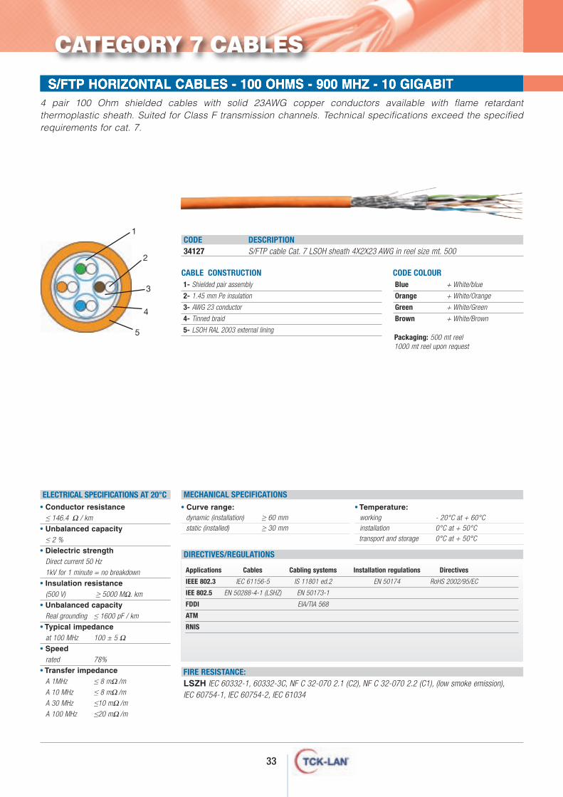
FLOOR RACKS - 600x600 - 600x800 - 800x600 - 800x800S/FTP HORIZONTAL CABLES - 100 OHMS - 900 MHZ - 10 GIGABIT4 pair 100 Ohm shielded cables with solid 23AWG copper conductors available with flame retardantthermoplastic sheath. Suited for Class F transmission channels. Technical specifications exceed the specifiedrequirements for cat. 7.
Packaging: 500 mt reel1000 mt reel upon request
• Curve range:dynamic (installation) ≥ 60 mmstatic (installed) ≥ 30 mm
• Temperature:working - 20°C at + 60°Cinstallation 0°C at + 50°Ctransport and storage 0°C at + 50°C
MECHANICAL SPECIFICATIONS
FIRE RESISTANCE:LSZH IEC 60332-1, 60332-3C, NF C 32-070 2.1 (C2), NF C 32-070 2.2 (C1), (low smoke emission), IEC 60754-1, IEC 60754-2, IEC 61034
• Conductor resistance≤ 146.4 Ω / km
• Unbalanced capacity≤ 2 %
• Dielectric strengthDirect current 50 Hz
1kV for 1 minute = no breakdown
• Insulation resistance(500 V) ≥ 5000 MΩ. km
• Unbalanced capacityReal grounding ≤ 1600 pF / km
• Typical impedanceat 100 MHz 100 ± 5 Ω
• Speedrated 78%
• Transfer impedanceA 1MHz ≤ 8 mΩ/m
A 10 MHz ≤ 8 mΩ/m
A 30 MHz ≤10 mΩ/m
A 100 MHz ≤20 mΩ/m
Applications Cables Cabling systems Installation regulations Directives
IEEE 802.3 IEC 61156-5 IS 11801 ed.2 EN 50174 RoHS 2002/95/EC
IEE 802.5 EN 50288-4-1 (LSHZ) EN 50173-1
FDDI EIA/TIA 568
ATM
RNIS
DIRECTIVES/REGULATIONS
ELECTRICAL SPECIFICATIONS AT 20°C
CABLE CONSTRUCTION1- Shielded pair assembly
2- 1.45 mm Pe insulation
3- AWG 23 conductor
4- Tinned braid
5- LSOH RAL 2003 external lining
CODE DESCRIPTION34127 S/FTP cable Cat. 7 LSOH sheath 4X2X23 AWG in reel size mt. 500
CODE COLOURBlue + White/blue
Orange + White/Orange
Green + White/Green
Brown + White/Brown
1
2
5
3
4
CATEGORY 7 CABLES
34
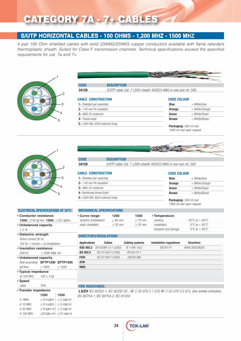
FLOOR RACKS - 600x600 - 600x800 - 800x600 - 800x800S/UTP HORIZONTAL CABLES - 100 OHMS - 1,200 MHZ - 1500 MHZ4 pair 100 Ohm shielded cables with solid 23AWG/22AWG copper conductors available with flame retardantthermoplastic sheath. Suited for Class F transmission channels. Technical specifications exceed the specifiedrequirements for cat. 7a and 7+.
CABLE CONSTRUCTION1- Shielded pair assembly
2- 1.45 mm Pe insulation
3- AWG 23 conductor
4- Tinned braid
5- LSOH RAL 6024 external lining
• Curve range: 1200 1500dynamic (installation) ≥ 60 mm ≥ 70 mmstatic (installed) ≥ 30 mm ≥ 35 mm
• Temperature:working - 20°C at + 60°Cinstallation 0°C at + 50°Ctransport and storage 0°C at + 50°C
MECHANICAL SPECIFICATIONS
FIRE RESISTANCE:LSZH IEC 60332-1, IEC 60332-3C , NF C 32-070 2.1 (C2) NF C 32-070 2.2 (C1), (low smoke emission),
IEC 60754-1, IEC 60754-2, IEC 61034
CODE DESCRIPTION34128 S/STP cable Cat. 7 LSOH sheath 4X2X23 AWG in reel size mt. 500
Applications Cables Cabling systems Installation regulations Directives
IEEE 802.3 EN 50288-12-1 (LSHZ) IS 11801 ed.2 EN 50174 RoHS 2002/95/EC
IEE 802.5 IEC 61156-5 (1200) EN 50173-1
FDDI IEC 61156-7 (1500) EIA/TIA 568
ATM
RNIS
DIRECTIVES/REGULATIONS
CODE COLOURBlue + White/blue
Orange + White/Orange
Green + White/Green
Brown + White/Brown
1
5
CODE DESCRIPTION34129 S/STP cable Cat. 7 LSOH sheath 4X2X23 AWG in reel size mt. 500
CODE COLOURBlue + White/blue
Orange + White/Orange
Green + White/Green
Brown + White/Brown
ELECTRICAL SPECIFICATIONS AT 20°C
3
4
CABLE CONSTRUCTION1- Shielded pair assembly
2- 1.45 mm Pe insulation
3- AWG 23 conductor
4- Reinforced tinned braid
5- LSOH RAL 6024 external lining
• Conductor resistance1200: ≤140 Ω/km 1500: ≤120 Ω/km
• Unbalanced capacity≤ 2 %
• Dielectric strengthDirect current 50 Hz
1kV for 1 minute = no breakdown
• Insulation resistance(500 V) ≥ 5000 MΩ. km
• Unbalanced capacityReal grounding SFTP1200 SFTP1500(pF/km) ≤ 1600 ≤ 1200
• Typical impedanceat 100 MHz 100 ± 5 Ω
• Speedrated 78%
• Transfer impedance1200 1500
A 1MHz ≤ 8 mΩ/m ≤ 5 mΩ/m
A 10 MHz ≤ 8 mΩ/m ≤ 5 mΩ/m
A 30 MHz ≤10 Ωm/m ≤ 5 mΩ/m
A 100 MHz ≤20 Ωm/m ≤10 mΩ/m
2
1
5
3
4
2
Packaging: 500 mt reel1000 mt reel upon request
Packaging: 500 mt reel1000 mt reel upon request
CATEGORY 7A - 7+ CABLES
35
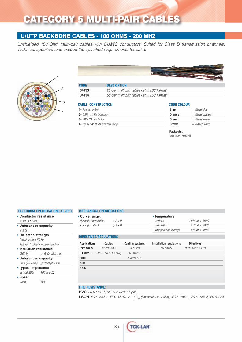
FLOOR RACKS - 600x600 - 600x800 - 800x600 - 800x800U/UTP BACKBONE CABLES - 100 OHMS - 200 MHZUnshielded 100 Ohm multi-pair cables with 24AWG conductors. Suited for Class D transmission channels.Technical specifications exceed the specified requirements for cat. 5.
PackagingSize upon request
• Curve range:dynamic (installation) ≥ 8 x Dstatic (installed) ≥ 4 x D
• Temperature:working - 20°C at + 60°Cinstallation 0°C at + 50°Ctransport and storage 0°C at + 50°C
MECHANICAL SPECIFICATIONS
FIRE RESISTANCE:PVC IEC 60332-1, NF C 32-070 2.1 (C2)LSOH IEC 60332-1, NF C 32-070 2.1 (C2), (low smoke emission), IEC 60754-1, IEC 60754-2, IEC 61034
• Conductor resistance≤ 190 Ω / km
• Unbalanced capacity≤ 2 %
• Dielectric strengthDirect current 50 Hz
1kV for 1 minute = no breakdown
• Insulation resistance(500 V) ≥ 5000 MΩ . km
• Unbalanced capacityReal grounding ≤ 1600 pF / km
• Typical impedanceat 100 MHz 100 ± 5 Ω
• Speedrated 66%
Applications Cables Cabling systems Installation regulations Directives
IEEE 802.3 IEC 61156-5 IS 11801 EN 50174 RoHS 2002/95/EC
IEE 802.5 EN 50288-3-1 (LSHZ) EN 50173-1
FDDI EIA/TIA 568
ATM
RNIS
DIRECTIVES/REGULATIONS
ELECTRICAL SPECIFICATIONS AT 20°C
CABLE CONSTRUCTION1- Pair assembly
2- 0.90 mm Pe insulation
3- AWG 24 conductor
4- LSOH RAL 9001 external lining
CODE DESCRIPTION34133 25-pair multi-pair cables Cat. 5 LSOH sheath34134 50-pair multi-pair cables Cat. 5 LSOH sheath
CODE COLOURBlue + White/blue
Orange + White/Orange
Green + White/Green
Brown + White/Brown
1
2
3
4
CATEGORY 5 MULTI-PAIR CABLES
36
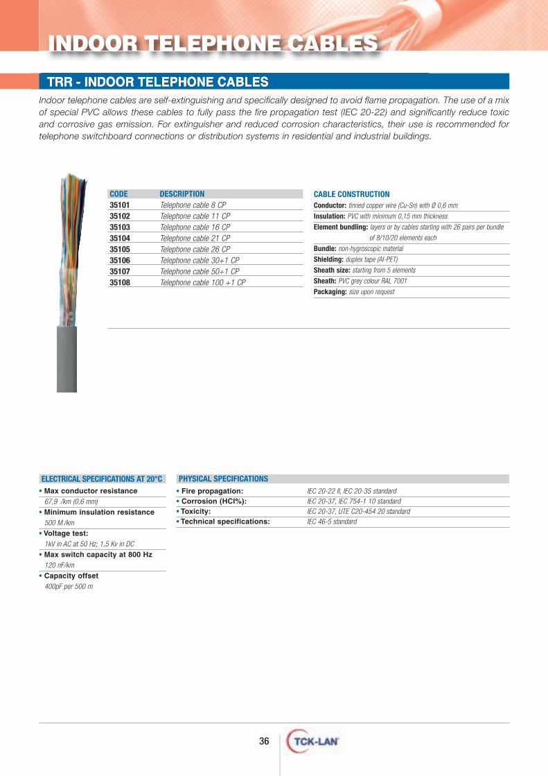
FLOOR RACKS - 600x600 - 600x800 - 800x600 - 800x800TRR - INDOOR TELEPHONE CABLES Indoor telephone cables are self-extinguishing and specifically designed to avoid flame propagation. The use of a mixof special PVC allows these cables to fully pass the fire propagation test (IEC 20-22) and significantly reduce toxicand corrosive gas emission. For extinguisher and reduced corrosion characteristics, their use is recommended fortelephone switchboard connections or distribution systems in residential and industrial buildings.
CABLE CONSTRUCTION Conductor: tinned copper wire (Cu-Sn) with Ø 0,6 mm
Insulation: PVC with minimum 0,15 mm thickness
Element bundling: layers or by cables starting with 26 pairs per bundle
of 8/10/20 elements each
Bundle: non-hygroscopic material
Shielding: duplex tape (AI-PET)
Sheath size: starting from 5 elements
Sheath: PVC grey colour RAL 7001
Packaging: size upon request
• Fire propagation: IEC 20-22 II, IEC 20-35 standard• Corrosion (HCI%): IEC 20-37, IEC 754-1 10 standard• Toxicity: IEC 20-37, UTE C20-454 20 standard• Technical specifications: IEC 46-5 standard
PHYSICAL SPECIFICATIONSELECTRICAL SPECIFICATIONS AT 20°C• Max conductor resistance
67,9 /km (0,6 mm)
• Minimum insulation resistance500 M/km
• Voltage test:1kV in AC at 50 Hz; 1,5 Kv in DC
• Max switch capacity at 800 Hz120 nF/km
• Capacity offset400pF per 500 m
CODE DESCRIPTION35101 Telephone cable 8 CP35102 Telephone cable 11 CP35103 Telephone cable 16 CP35104 Telephone cable 21 CP35105 Telephone cable 26 CP35106 Telephone cable 30+1 CP35107 Telephone cable 50+1 CP35108 Telephone cable 100 +1 CP
INDOOR TELEPHONE CABLES
37
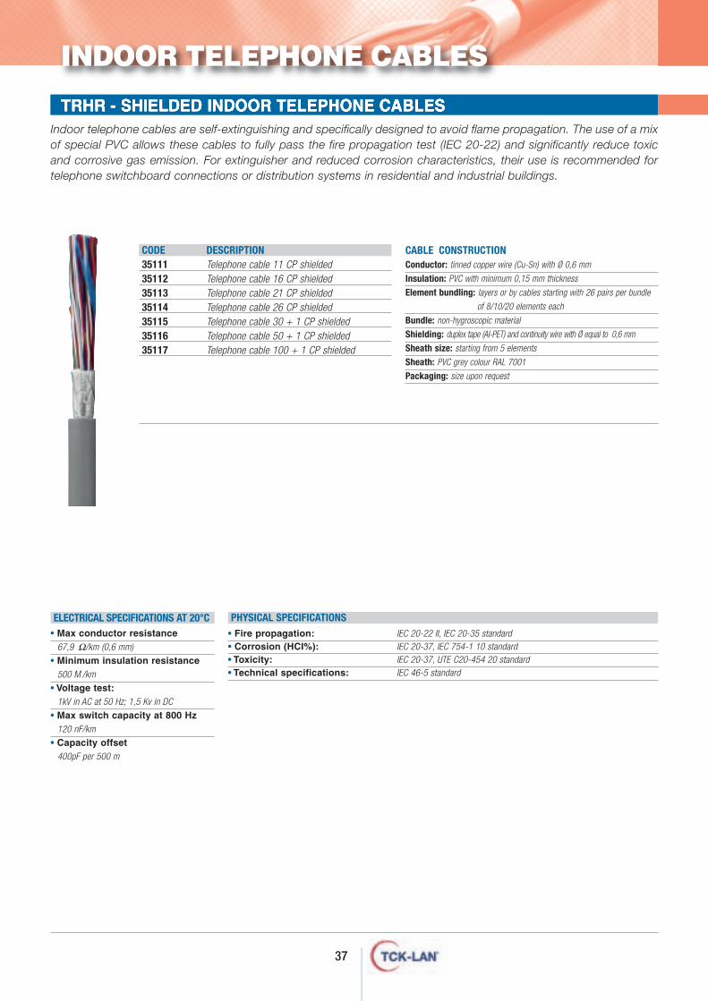
FLOOR RACKS - 600x600 - 600x800 - 800x600 - 800x800TRHR - SHIELDED INDOOR TELEPHONE CABLES Indoor telephone cables are self-extinguishing and specifically designed to avoid flame propagation. The use of a mixof special PVC allows these cables to fully pass the fire propagation test (IEC 20-22) and significantly reduce toxicand corrosive gas emission. For extinguisher and reduced corrosion characteristics, their use is recommended fortelephone switchboard connections or distribution systems in residential and industrial buildings.
• Fire propagation: IEC 20-22 II, IEC 20-35 standard• Corrosion (HCI%): IEC 20-37, IEC 754-1 10 standard• Toxicity: IEC 20-37, UTE C20-454 20 standard• Technical specifications: IEC 46-5 standard
PHYSICAL SPECIFICATIONSELECTRICAL SPECIFICATIONS AT 20°C• Max conductor resistance
67,9 Ω/km (0,6 mm)
• Minimum insulation resistance500 M/km
• Voltage test:1kV in AC at 50 Hz; 1,5 Kv in DC
• Max switch capacity at 800 Hz120 nF/km
• Capacity offset400pF per 500 m
CODE DESCRIPTION35111 Telephone cable 11 CP shielded35112 Telephone cable 16 CP shielded35113 Telephone cable 21 CP shielded35114 Telephone cable 26 CP shielded35115 Telephone cable 30 + 1 CP shielded35116 Telephone cable 50 + 1 CP shielded35117 Telephone cable 100 + 1 CP shielded
CABLE CONSTRUCTIONConductor: tinned copper wire (Cu-Sn) with Ø 0,6 mm
Insulation: PVC with minimum 0,15 mm thickness
Element bundling: layers or by cables starting with 26 pairs per bundle
of 8/10/20 elements each
Bundle: non-hygroscopic material
Shielding: duplex tape (AI-PET) and continuity wire with Ø equal to 0,6 mm
Sheath size: starting from 5 elements
Sheath: PVC grey colour RAL 7001
Packaging: size upon request
INDOOR TELEPHONE CABLES
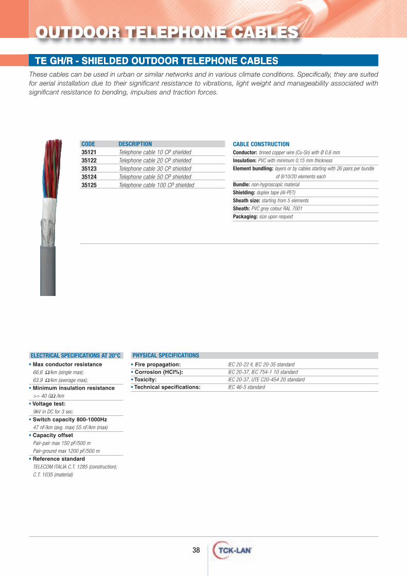
FLOOR RACKS - 600x600 - 600x800 - 800x600 - 800x800TE GH/R - SHIELDED OUTDOOR TELEPHONE CABLES These cables can be used in urban or similar networks and in various climate conditions. Specifically, they are suitedfor aerial installation due to their significant resistance to vibrations, light weight and manageability associated withsignificant resistance to bending, impulses and traction forces.
CABLE CONSTRUCTION Conductor: tinned copper wire (Cu-Sn) with Ø 0,6 mm
Insulation: PVC with minimum 0,15 mm thickness
Element bundling: layers or by cables starting with 26 pairs per bundle
of 8/10/20 elements each
Bundle: non-hygroscopic material
Shielding: duplex tape (AI-PET)
Sheath size: starting from 5 elements
Sheath: PVC grey colour RAL 7001
Packaging: size upon request
CODE DESCRIPTION35121 Telephone cable 10 CP shielded35122 Telephone cable 20 CP shielded35123 Telephone cable 30 CP shielded35124 Telephone cable 50 CP shielded35125 Telephone cable 100 CP shielded
• Fire propagation: IEC 20-22 II, IEC 20-35 standard• Corrosion (HCI%): IEC 20-37, IEC 754-1 10 standard• Toxicity: IEC 20-37, UTE C20-454 20 standard• Technical specifications: IEC 46-5 standard
PHYSICAL SPECIFICATIONSELECTRICAL SPECIFICATIONS AT 20°C• Max conductor resistance
66,6 Ω/km (single max);
63.9 Ω/km (average max);
• Minimum insulation resistance>= 40 GΩ/km
• Voltage test:9kV in DC for 3 sec.
• Switch capacity 800-1000Hz47 nF/km (avg. max) 55 nF/km (max)
• Capacity offsetPair-pair max 150 pF/500 m
Pair-ground max 1200 pF/500 m
• Reference standardTELECOM ITALIA C.T. 1285 (construction);
C.T. 1035 (material)
OUTDOOR TELEPHONE CABLES
38
ptical fibre cables
O
Optical fibre is a transmission support that carries photons (light) instead ofelectricity, as occurs in copper conductors.TCK-LAN® manages a complete range ofcables for optical fibre cabling, type OM1,OM2 ENHANCED, OM3, OM4, OS1.Some advantages of fibre cabling over copper are:- very large bandwidth;- long distance transmission;- high information transport
capacity:- immunity to electromagnetic
disturbances;- excellent resistance to climate
conditions.
40
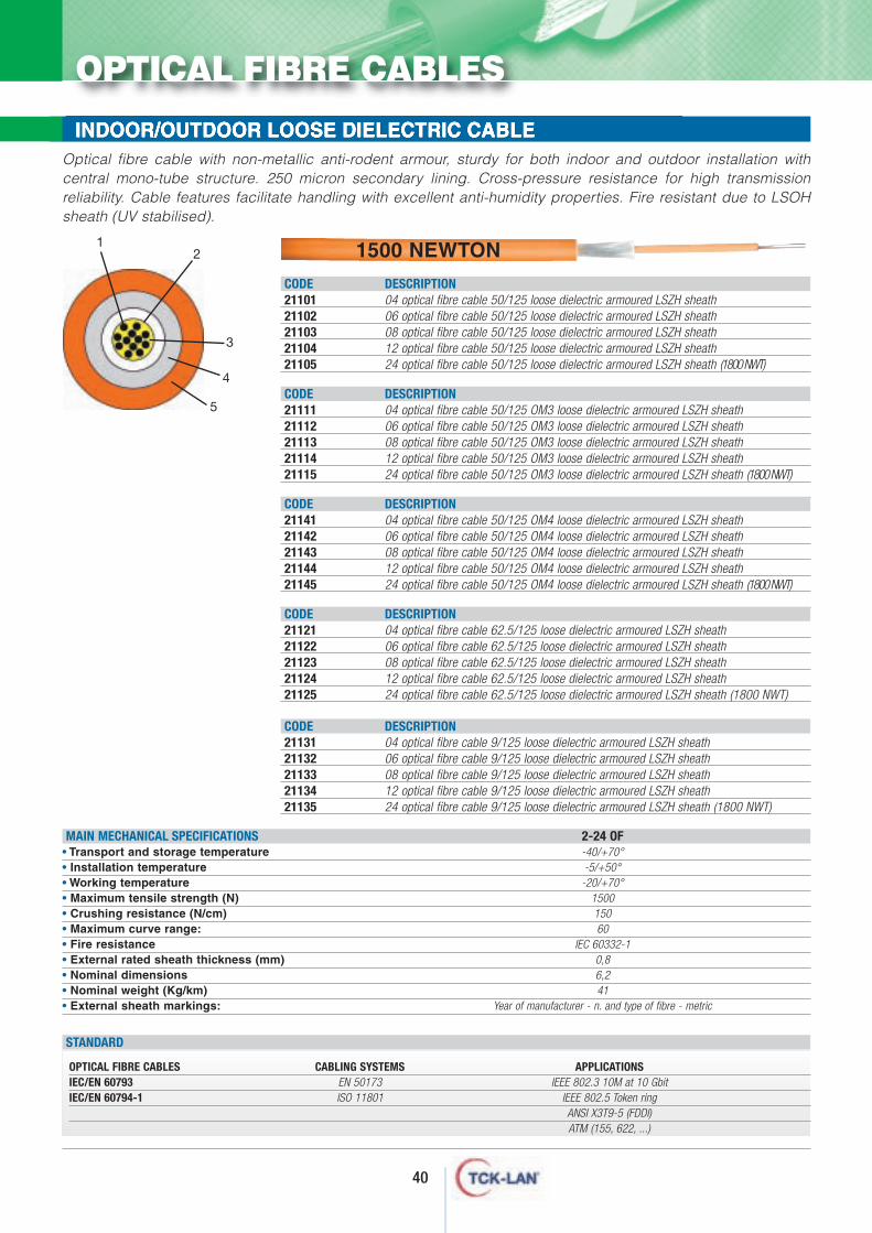
FLOOR RACKS - 600x600 - 600x800 - 800x600 - 800x800INDOOR/OUTDOOR LOOSE DIELECTRIC CABLE
MAIN MECHANICAL SPECIFICATIONS 2-24 OF• Transport and storage temperature -40/+70°• Installation temperature -5/+50°• Working temperature -20/+70°• Maximum tensile strength (N) 1500• Crushing resistance (N/cm) 150• Maximum curve range: 60• Fire resistance IEC 60332-1• External rated sheath thickness (mm) 0,8• Nominal dimensions 6,2• Nominal weight (Kg/km) 41• External sheath markings: Year of manufacturer - n. and type of fibre - metric
CODE DESCRIPTION21101 04 optical fibre cable 50/125 loose dielectric armoured LSZH sheath21102 06 optical fibre cable 50/125 loose dielectric armoured LSZH sheath21103 08 optical fibre cable 50/125 loose dielectric armoured LSZH sheath21104 12 optical fibre cable 50/125 loose dielectric armoured LSZH sheath21105 24 optical fibre cable 50/125 loose dielectric armoured LSZH sheath (1800 NWT)
CODE DESCRIPTION21111 04 optical fibre cable 50/125 OM3 loose dielectric armoured LSZH sheath21112 06 optical fibre cable 50/125 OM3 loose dielectric armoured LSZH sheath21113 08 optical fibre cable 50/125 OM3 loose dielectric armoured LSZH sheath21114 12 optical fibre cable 50/125 OM3 loose dielectric armoured LSZH sheath21115 24 optical fibre cable 50/125 OM3 loose dielectric armoured LSZH sheath (1800 NWT)
CODE DESCRIPTION21141 04 optical fibre cable 50/125 OM4 loose dielectric armoured LSZH sheath21142 06 optical fibre cable 50/125 OM4 loose dielectric armoured LSZH sheath21143 08 optical fibre cable 50/125 OM4 loose dielectric armoured LSZH sheath21144 12 optical fibre cable 50/125 OM4 loose dielectric armoured LSZH sheath21145 24 optical fibre cable 50/125 OM4 loose dielectric armoured LSZH sheath (1800 NWT)
CODE DESCRIPTION21121 04 optical fibre cable 62.5/125 loose dielectric armoured LSZH sheath21122 06 optical fibre cable 62.5/125 loose dielectric armoured LSZH sheath21123 08 optical fibre cable 62.5/125 loose dielectric armoured LSZH sheath21124 12 optical fibre cable 62.5/125 loose dielectric armoured LSZH sheath21125 24 optical fibre cable 62.5/125 loose dielectric armoured LSZH sheath (1800 NWT)
CODE DESCRIPTION21131 04 optical fibre cable 9/125 loose dielectric armoured LSZH sheath21132 06 optical fibre cable 9/125 loose dielectric armoured LSZH sheath21133 08 optical fibre cable 9/125 loose dielectric armoured LSZH sheath21134 12 optical fibre cable 9/125 loose dielectric armoured LSZH sheath21135 24 optical fibre cable 9/125 loose dielectric armoured LSZH sheath (1800 NWT)
OPTICAL FIBRE CABLES CABLING SYSTEMS APPLICATIONSIEC/EN 60793 EN 50173 IEEE 802.3 10M at 10 GbitIEC/EN 60794-1 ISO 11801 IEEE 802.5 Token ring
ANSI X3T9-5 (FDDI)ATM (155, 622, ...)
STANDARD
12
Optical fibre cable with non-metallic anti-rodent armour, sturdy for both indoor and outdoor installation withcentral mono-tube structure. 250 micron secondary lining. Cross-pressure resistance for high transmissionreliability. Cable features facilitate handling with excellent anti-humidity properties. Fire resistant due to LSOHsheath (UV stabilised).
3
4
5
OPTICAL FIBRE CABLES
1500 NEWTON
41
OPTICAL FIBRE CABLES
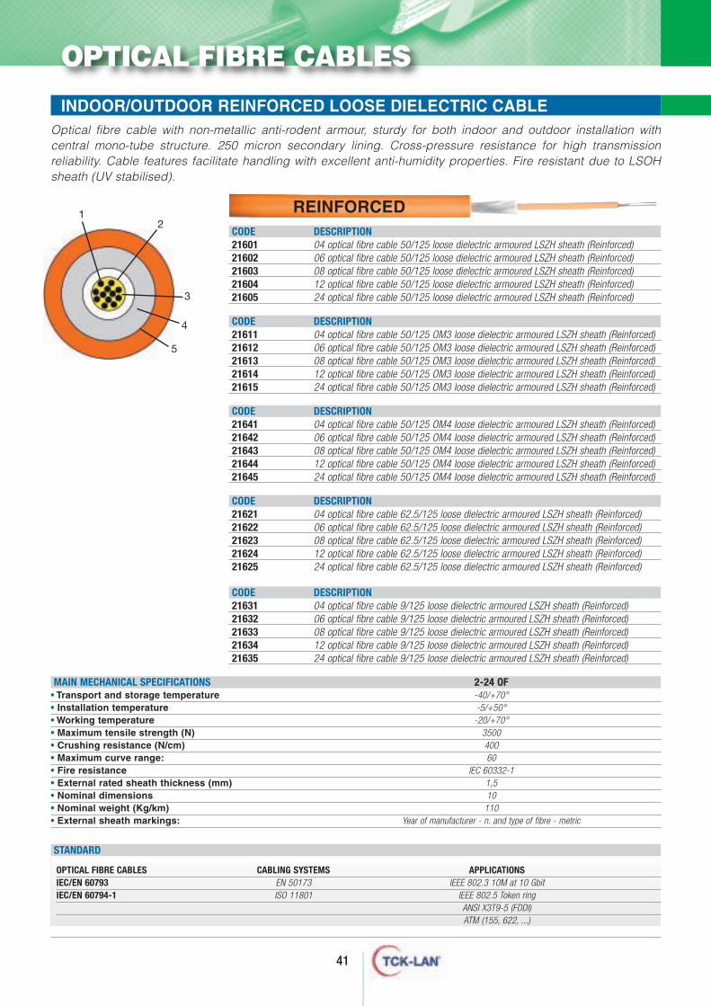
INDOOR/OUTDOOR REINFORCED LOOSE DIELECTRIC CABLE
MAIN MECHANICAL SPECIFICATIONS 2-24 OF• Transport and storage temperature -40/+70°• Installation temperature -5/+50°• Working temperature -20/+70°• Maximum tensile strength (N) 3500• Crushing resistance (N/cm) 400• Maximum curve range: 60• Fire resistance IEC 60332-1• External rated sheath thickness (mm) 1,5• Nominal dimensions 10• Nominal weight (Kg/km) 110• External sheath markings: Year of manufacturer - n. and type of fibre - metric
CODE DESCRIPTION21601 04 optical fibre cable 50/125 loose dielectric armoured LSZH sheath (Reinforced)21602 06 optical fibre cable 50/125 loose dielectric armoured LSZH sheath (Reinforced)21603 08 optical fibre cable 50/125 loose dielectric armoured LSZH sheath (Reinforced)21604 12 optical fibre cable 50/125 loose dielectric armoured LSZH sheath (Reinforced)21605 24 optical fibre cable 50/125 loose dielectric armoured LSZH sheath (Reinforced)
CODE DESCRIPTION21611 04 optical fibre cable 50/125 OM3 loose dielectric armoured LSZH sheath (Reinforced)21612 06 optical fibre cable 50/125 OM3 loose dielectric armoured LSZH sheath (Reinforced)21613 08 optical fibre cable 50/125 OM3 loose dielectric armoured LSZH sheath (Reinforced)21614 12 optical fibre cable 50/125 OM3 loose dielectric armoured LSZH sheath (Reinforced)21615 24 optical fibre cable 50/125 OM3 loose dielectric armoured LSZH sheath (Reinforced)
CODE DESCRIPTION21641 04 optical fibre cable 50/125 OM4 loose dielectric armoured LSZH sheath (Reinforced)21642 06 optical fibre cable 50/125 OM4 loose dielectric armoured LSZH sheath (Reinforced)21643 08 optical fibre cable 50/125 OM4 loose dielectric armoured LSZH sheath (Reinforced)21644 12 optical fibre cable 50/125 OM4 loose dielectric armoured LSZH sheath (Reinforced)21645 24 optical fibre cable 50/125 OM4 loose dielectric armoured LSZH sheath (Reinforced)
CODE DESCRIPTION21621 04 optical fibre cable 62.5/125 loose dielectric armoured LSZH sheath (Reinforced)21622 06 optical fibre cable 62.5/125 loose dielectric armoured LSZH sheath (Reinforced)21623 08 optical fibre cable 62.5/125 loose dielectric armoured LSZH sheath (Reinforced)21624 12 optical fibre cable 62.5/125 loose dielectric armoured LSZH sheath (Reinforced)21625 24 optical fibre cable 62.5/125 loose dielectric armoured LSZH sheath (Reinforced)
CODE DESCRIPTION21631 04 optical fibre cable 9/125 loose dielectric armoured LSZH sheath (Reinforced)21632 06 optical fibre cable 9/125 loose dielectric armoured LSZH sheath (Reinforced)21633 08 optical fibre cable 9/125 loose dielectric armoured LSZH sheath (Reinforced)21634 12 optical fibre cable 9/125 loose dielectric armoured LSZH sheath (Reinforced)21635 24 optical fibre cable 9/125 loose dielectric armoured LSZH sheath (Reinforced)
OPTICAL FIBRE CABLES CABLING SYSTEMS APPLICATIONSIEC/EN 60793 EN 50173 IEEE 802.3 10M at 10 GbitIEC/EN 60794-1 ISO 11801 IEEE 802.5 Token ring
ANSI X3T9-5 (FDDI)ATM (155, 622, ...)
STANDARD
12
Optical fibre cable with non-metallic anti-rodent armour, sturdy for both indoor and outdoor installation withcentral mono-tube structure. 250 micron secondary lining. Cross-pressure resistance for high transmissionreliability. Cable features facilitate handling with excellent anti-humidity properties. Fire resistant due to LSOHsheath (UV stabilised).
3
4
5
REINFORCED
42
OPTICAL FIBRE CABLES
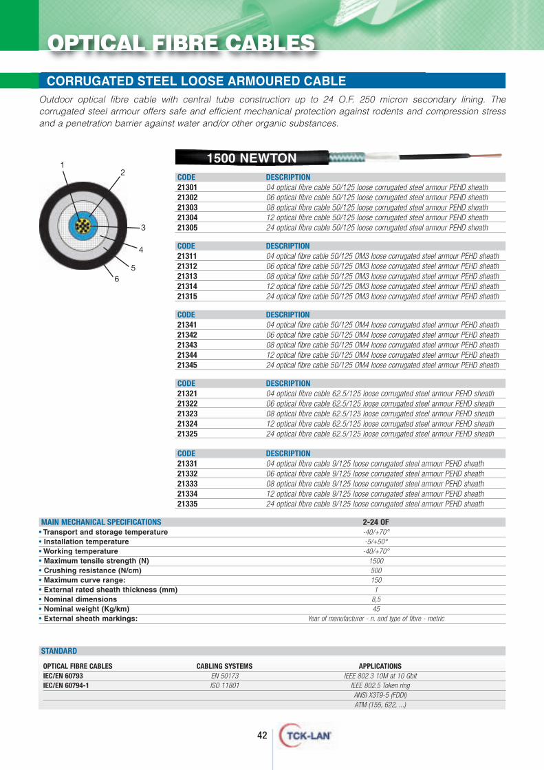
CORRUGATED STEEL LOOSE ARMOURED CABLE
MAIN MECHANICAL SPECIFICATIONS 2-24 OF• Transport and storage temperature -40/+70°• Installation temperature -5/+50°• Working temperature -40/+70°• Maximum tensile strength (N) 1500• Crushing resistance (N/cm) 500• Maximum curve range: 150• External rated sheath thickness (mm) 1• Nominal dimensions 8,5• Nominal weight (Kg/km) 45• External sheath markings: Year of manufacturer - n. and type of fibre - metric
CODE DESCRIPTION21301 04 optical fibre cable 50/125 loose corrugated steel armour PEHD sheath21302 06 optical fibre cable 50/125 loose corrugated steel armour PEHD sheath21303 08 optical fibre cable 50/125 loose corrugated steel armour PEHD sheath21304 12 optical fibre cable 50/125 loose corrugated steel armour PEHD sheath21305 24 optical fibre cable 50/125 loose corrugated steel armour PEHD sheath
CODE DESCRIPTION21311 04 optical fibre cable 50/125 OM3 loose corrugated steel armour PEHD sheath21312 06 optical fibre cable 50/125 OM3 loose corrugated steel armour PEHD sheath21313 08 optical fibre cable 50/125 OM3 loose corrugated steel armour PEHD sheath21314 12 optical fibre cable 50/125 OM3 loose corrugated steel armour PEHD sheath21315 24 optical fibre cable 50/125 OM3 loose corrugated steel armour PEHD sheath
CODE DESCRIPTION21341 04 optical fibre cable 50/125 OM4 loose corrugated steel armour PEHD sheath21342 06 optical fibre cable 50/125 OM4 loose corrugated steel armour PEHD sheath21343 08 optical fibre cable 50/125 OM4 loose corrugated steel armour PEHD sheath21344 12 optical fibre cable 50/125 OM4 loose corrugated steel armour PEHD sheath21345 24 optical fibre cable 50/125 OM4 loose corrugated steel armour PEHD sheath
CODE DESCRIPTION21321 04 optical fibre cable 62.5/125 loose corrugated steel armour PEHD sheath21322 06 optical fibre cable 62.5/125 loose corrugated steel armour PEHD sheath21323 08 optical fibre cable 62.5/125 loose corrugated steel armour PEHD sheath21324 12 optical fibre cable 62.5/125 loose corrugated steel armour PEHD sheath21325 24 optical fibre cable 62.5/125 loose corrugated steel armour PEHD sheath
CODE DESCRIPTION21331 04 optical fibre cable 9/125 loose corrugated steel armour PEHD sheath21332 06 optical fibre cable 9/125 loose corrugated steel armour PEHD sheath21333 08 optical fibre cable 9/125 loose corrugated steel armour PEHD sheath21334 12 optical fibre cable 9/125 loose corrugated steel armour PEHD sheath21335 24 optical fibre cable 9/125 loose corrugated steel armour PEHD sheath
OPTICAL FIBRE CABLES CABLING SYSTEMS APPLICATIONSIEC/EN 60793 EN 50173 IEEE 802.3 10M at 10 GbitIEC/EN 60794-1 ISO 11801 IEEE 802.5 Token ring
ANSI X3T9-5 (FDDI)ATM (155, 622, ...)
STANDARD
12
Outdoor optical fibre cable with central tube construction up to 24 O.F. 250 micron secondary lining. Thecorrugated steel armour offers safe and efficient mechanical protection against rodents and compression stressand a penetration barrier against water and/or other organic substances.
3
4
56
1500 NEWTON
43
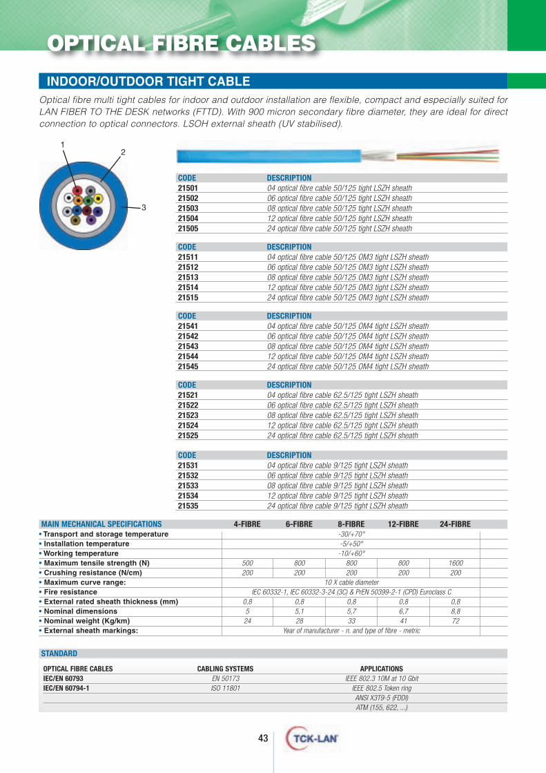
OPTICAL FIBRE CABLES
MAIN MECHANICAL SPECIFICATIONS 4-FIBRE 6-FIBRE 8-FIBRE 12-FIBRE 24-FIBRE• Transport and storage temperature -30/+70°• Installation temperature -5/+50°• Working temperature -10/+60°• Maximum tensile strength (N) 500 800 800 800 1600• Crushing resistance (N/cm) 200 200 200 200 200• Maximum curve range: 10 X cable diameter• Fire resistance IEC 60332-1, IEC 60332-3-24 (3C) & PrEN 50399-2-1 (CPD) Euroclass C• External rated sheath thickness (mm) 0,8 0,8 0,8 0,8 0,8• Nominal dimensions 5 5,1 5,7 6,7 8,8• Nominal weight (Kg/km) 24 28 33 41 72• External sheath markings: Year of manufacturer - n. and type of fibre - metric
CODE DESCRIPTION21501 04 optical fibre cable 50/125 tight LSZH sheath21502 06 optical fibre cable 50/125 tight LSZH sheath21503 08 optical fibre cable 50/125 tight LSZH sheath21504 12 optical fibre cable 50/125 tight LSZH sheath21505 24 optical fibre cable 50/125 tight LSZH sheath
CODE DESCRIPTION21511 04 optical fibre cable 50/125 OM3 tight LSZH sheath21512 06 optical fibre cable 50/125 OM3 tight LSZH sheath21513 08 optical fibre cable 50/125 OM3 tight LSZH sheath21514 12 optical fibre cable 50/125 OM3 tight LSZH sheath21515 24 optical fibre cable 50/125 OM3 tight LSZH sheath
CODE DESCRIPTION21541 04 optical fibre cable 50/125 OM4 tight LSZH sheath21542 06 optical fibre cable 50/125 OM4 tight LSZH sheath21543 08 optical fibre cable 50/125 OM4 tight LSZH sheath21544 12 optical fibre cable 50/125 OM4 tight LSZH sheath21545 24 optical fibre cable 50/125 OM4 tight LSZH sheath
CODE DESCRIPTION21521 04 optical fibre cable 62.5/125 tight LSZH sheath21522 06 optical fibre cable 62.5/125 tight LSZH sheath21523 08 optical fibre cable 62.5/125 tight LSZH sheath21524 12 optical fibre cable 62.5/125 tight LSZH sheath21525 24 optical fibre cable 62.5/125 tight LSZH sheath
CODE DESCRIPTION21531 04 optical fibre cable 9/125 tight LSZH sheath21532 06 optical fibre cable 9/125 tight LSZH sheath21533 08 optical fibre cable 9/125 tight LSZH sheath21534 12 optical fibre cable 9/125 tight LSZH sheath21535 24 optical fibre cable 9/125 tight LSZH sheath
12
Optical fibre multi tight cables for indoor and outdoor installation are flexible, compact and especially suited forLAN FIBER TO THE DESK networks (FTTD). With 900 micron secondary fibre diameter, they are ideal for directconnection to optical connectors. LSOH external sheath (UV stabilised).
3
OPTICAL FIBRE CABLES CABLING SYSTEMS APPLICATIONSIEC/EN 60793 EN 50173 IEEE 802.3 10M at 10 GbitIEC/EN 60794-1 ISO 11801 IEEE 802.5 Token ring
ANSI X3T9-5 (FDDI)ATM (155, 622, ...)
STANDARD
INDOOR/OUTDOOR TIGHT CABLE
44
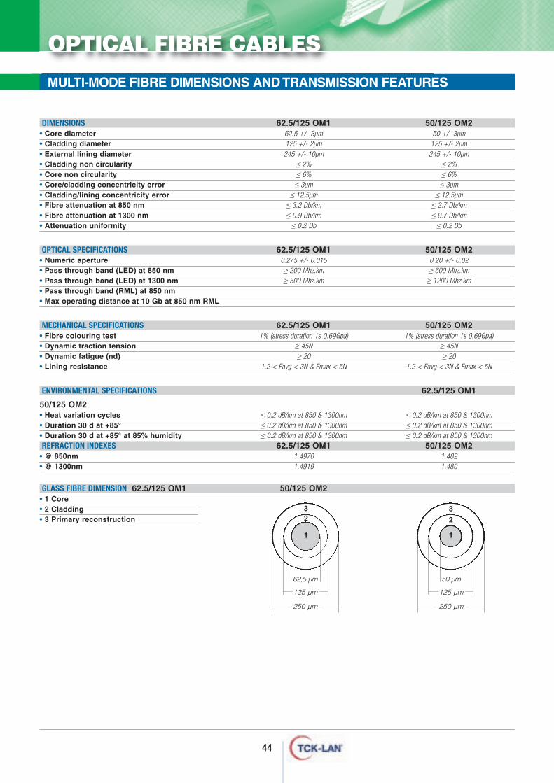
DIMENSIONS 62.5/125 OM1 50/125 OM2• Core diameter 62.5 +/- 3µm 50 +/- 3µm• Cladding diameter 125 +/- 2µm 125 +/- 2µm• External lining diameter 245 +/- 10µm 245 +/- 10µm• Cladding non circularity ≤ 2% ≤ 2%• Core non circularity ≤ 6% ≤ 6%• Core/cladding concentricity error ≤ 3µm ≤ 3µm• Cladding/lining concentricity error ≤ 12.5µm ≤ 12.5µm• Fibre attenuation at 850 nm ≤ 3.2 Db/km ≤ 2.7 Db/km• Fibre attenuation at 1300 nm ≤ 0.9 Db/km ≤ 0.7 Db/km• Attenuation uniformity ≤ 0.2 Db ≤ 0.2 Db
OPTICAL SPECIFICATIONS 62.5/125 OM1 50/125 OM2• Numeric aperture 0.275 +/- 0.015 0.20 +/- 0.02• Pass through band (LED) at 850 nm ≥ 200 Mhz.km ≥ 600 Mhz.km• Pass through band (LED) at 1300 nm ≥ 500 Mhz.km ≥ 1200 Mhz.km• Pass through band (RML) at 850 nm• Max operating distance at 10 Gb at 850 nm RML
MECHANICAL SPECIFICATIONS 62.5/125 OM1 50/125 OM2• Fibre colouring test 1% (stress duration 1s 0.69Gpa) 1% (stress duration 1s 0.69Gpa)• Dynamic traction tension ≥ 45N ≥ 45N• Dynamic fatigue (nd) ≥ 20 ≥ 20• Lining resistance 1.2 < Favg < 3N & Fmax < 5N 1.2 < Favg < 3N & Fmax < 5N
ENVIRONMENTAL SPECIFICATIONS 62.5/125 OM1
50/125 OM2• Heat variation cycles ≤ 0.2 dB/km at 850 & 1300nm ≤ 0.2 dB/km at 850 & 1300nm• Duration 30 d at +85° ≤ 0.2 dB/km at 850 & 1300nm ≤ 0.2 dB/km at 850 & 1300nm• Duration 30 d at +85° at 85% humidity ≤ 0.2 dB/km at 850 & 1300nm ≤ 0.2 dB/km at 850 & 1300nmREFRACTION INDEXES 62.5/125 OM1 50/125 OM2
• @ 850nm 1.4970 1.482• @ 1300nm 1.4919 1.480
GLASS FIBRE DIMENSION 62.5/125 OM1 50/125 OM2• 1 Core• 2 Cladding• 3 Primary reconstruction
125 µm
250 µm
50 µm
125 µm
250 µm
62,5 µm
11
23
23
OPTICAL FIBRE CABLES
MULTI-MODE FIBRE DIMENSIONS AND TRANSMISSION FEATURES
45
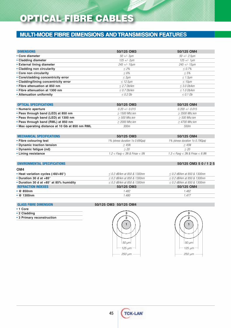
MULTI-MODE FIBRE DIMENSIONS AND TRANSMISSION FEATURES
DIMENSIONS 50/125 OM3 50/125 OM4• Core diameter 50 +/- 3µm 50 +/- 2.5µm• Cladding diameter 125 +/- 2µm 125 +/- 1µm• External lining diameter 245 +/- 10µm 245 +/- 15µm• Cladding non circularity ≤ 2% ≤ 0.7%• Core non circularity ≤ 6% ≤ 5%• Core/cladding concentricity error ≤ 3µm ≤ 1.5µm• Cladding/lining concentricity error ≤ 12.5µm ≤ 10µm• Fibre attenuation at 850 nm ≤ 2.7 Db/km ≤ 3.0 Db/km• Fibre attenuation at 1300 nm ≤ 0.7 Db/km ≤ 1.0 Db/km• Attenuation uniformity ≤ 0.2 Db ≤ 0.1 Db
OPTICAL SPECIFICATIONS 50/125 OM3 50/125 OM4• Numeric aperture 0.20 +/- 0.015 0.200 +/- 0.015• Pass through band (LED) at 850 nm ≥ 1500 Mhz.km ≥ 3500 Mhz.km• Pass through band (LED) at 1300 nm ≥ 500 Mhz.km ≥ 500 Mhz.km• Pass through band (RML) at 850 nm ≥ 2000 Mhz.km ≥ 4700 Mhz.km• Max operating distance at 10 Gb at 850 nm RML 300m 550m
MECHANICAL SPECIFICATIONS 50/125 OM3 50/125 OM4• Fibre colouring test 1% (stress duration 1s 0.69Gpa) 1% (stress duration 1s 0.79Gpa)• Dynamic traction tension ≥ 45N ≥ 45N• Dynamic fatigue (nd) ≥ 20 ≥ 20• Lining resistance 1.2 < Favg < 3N & Fmax < 5N 1.3 < Favg < 3N & Fmax < 8.9N
ENVIRONMENTAL SPECIFICATIONS 50/125 OM3 5 0 / 1 2 5
OM4• Heat variation cycles (-60/+85°) ≤ 0.2 dB/km at 850 & 1300nm ≤ 0.2 dB/km at 850 & 1300nm• Duration 30 d at +85° ≤ 0.2 dB/km at 850 & 1300nm ≤ 0.2 dB/km at 850 & 1300nm• Duration 30 d at +85° at 85% humidity ≤ 0.2 dB/km at 850 & 1300nm ≤ 0.2 dB/km at 850 & 1300nmREFRACTION INDEXES 50/125 OM3 50/125 OM4
• @ 850nm 1.482 1.482• @ 1300nm 1.480 1.477
GLASS FIBRE DIMENSION 50/125 OM3 50/125 OM4• 1 Core• 2 Cladding• 3 Primary reconstruction
125 µm
250 µm
50 µm
1
23
125 µm
250 µm
50 µm
1
23
OPTICAL FIBRE CABLES
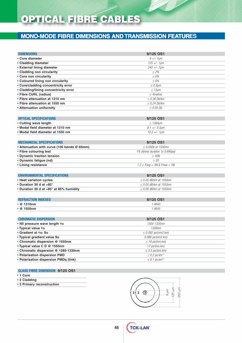
GLASS FIBRE DIMENSION 9/125 OS1• 1 Core• 2 Cladding• 3 Primary reconstruction
46
MONO-MODE FIBRE DIMENSIONS AND TRANSMISSION FEATURES
DIMENSIONS 9/125 OS1• Core diameter 9 +/- 1µm• Cladding diameter 125 +/- 1µm• External lining diameter 245 +/- 7µm• Cladding non circularity ≤ 2%• Core non circularity ≤ 6%• Coloured lining non circularity ≤ 6%• Core/cladding concentricity error ≤ 0.8µm• Cladding/lining concentricity error ≤ 12µm• Fibre CURL (radius) ≥ 4metres• Fibre attenuation at 1310 nm ≤ 0.38 Db/km• Fibre attenuation at 1550 nm ≤ 0.24 Db/km• Attenuation uniformity ≤ 0.05 Db
OPTICAL SPECIFICATIONS 9/125 OS1• Cutting wave length ≤ 1260µm• Modal field diameter at 1310 nm 9.1 +/- 0.5µm• Modal field diameter at 1550 nm 10.2 +/- 1µm
MECHANICAL SPECIFICATIONS 9/125 OS1• Attenuation with curve (100 bends Ø 60mm) ≤ 0.05Db at 1550nm• Fibre colouring test 1% (stress duration 1s 0.69Gpa)• Dynamic traction tension ≥ 45N• Dynamic fatigue (nd) ≥ 20• Lining resistance 1.2 < Favg < 3N & Fmax < 5N
ENVIRONMENTAL SPECIFICATIONS 9/125 OS1• Heat variation cycles ≤ 0.05 dB/km at 1550nm• Duration 30 d at +85° ≤ 0.05 dB/km at 1550nm• Duration 30 d at +85° at 85% humidity ≤ 0.05 dB/km at 1550nm
REFRACTION INDEXES 9/125 OS1• @ 1310nm 1.4640• @ 1550nm 1.4645
CHROMATIC DISPERSION 9/125 OS1• Nil pressure wave length ?o 1300-1320nm• Typical value ?o 1309nm• Gradient at ?o: So ≤ 0.092 ps/(nm2.km)• Typical gradient value So 0.086 ps/(nm2.km)• Chromatic dispersion @ 1550nm ≤ 18 ps/(nm.km)• Typical value C D @ 1550nm 17 ps/(nm.km)• Chromatic dispersion @ 1285-1330nm ≤ 3.5 ps/(nm.km)• Polarisation dispersion PMD ≤ 0.2 ps.km1/2
• Polarisation dispersion PMDq (link) ≤ 0.1 ps.km1/2
125
µm
250
µm
9 µm
123
OPTICAL FIBRE CABLES
47
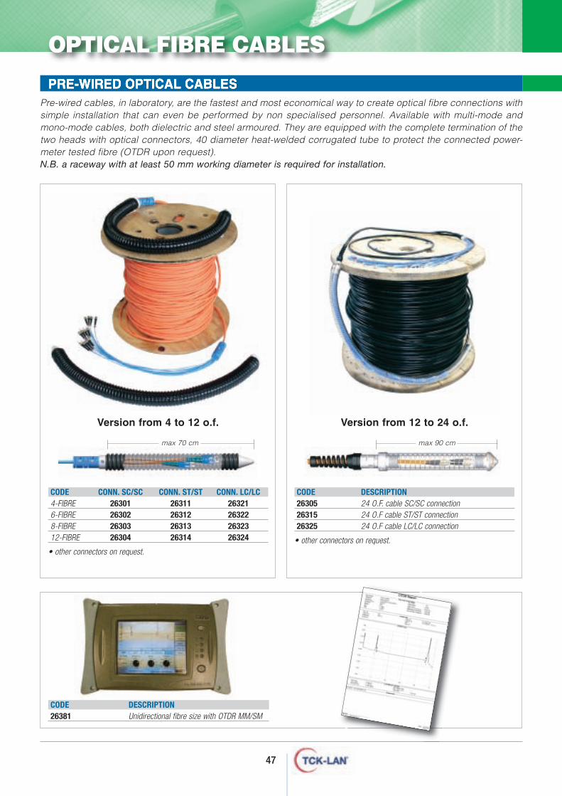
PRE-WIRED OPTICAL CABLES
CODE CONN. SC/SC CONN. ST/ST CONN. LC/LC4-FIBRE 26301 26311 263216-FIBRE 26302 26312 263228-FIBRE 26303 26313 2632312-FIBRE 26304 26314 26324
• other connectors on request.
CODE DESCRIPTION26305 24 O.F. cable SC/SC connection26315 24 O.F cable ST/ST connection26325 24 O.F cable LC/LC connection
• other connectors on request.
Pre-wired cables, in laboratory, are the fastest and most economical way to create optical fibre connections withsimple installation that can even be performed by non specialised personnel. Available with multi-mode andmono-mode cables, both dielectric and steel armoured. They are equipped with the complete termination of thetwo heads with optical connectors, 40 diameter heat-welded corrugated tube to protect the connected power-meter tested fibre (OTDR upon request). N.B. a raceway with at least 50 mm working diameter is required for installation.
CODE DESCRIPTION26381 Unidirectional fibre size with OTDR MM/SM
Version from 4 to 12 o.f. Version from 12 to 24 o.f.
OPTICAL FIBRE CABLES
max 70 cm max 90 cm
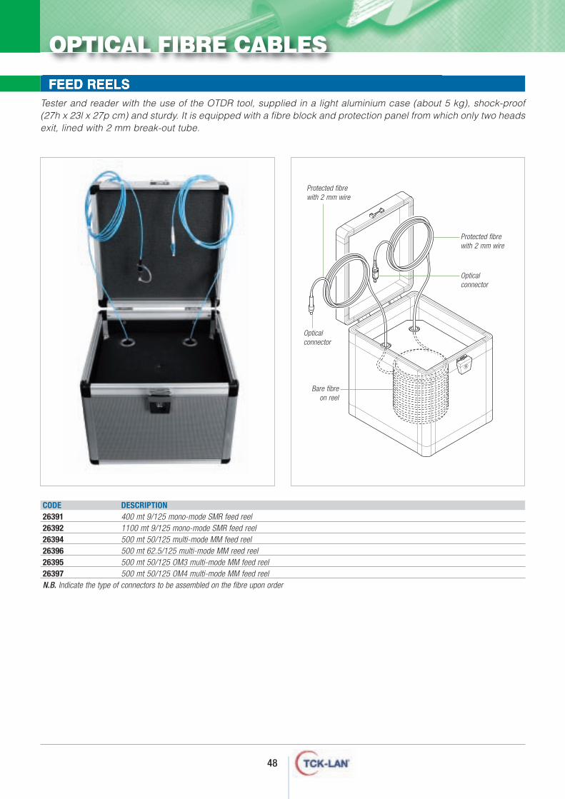
FEED REELS
CODE DESCRIPTION26391 400 mt 9/125 mono-mode SMR feed reel26392 1100 mt 9/125 mono-mode SMR feed reel26394 500 mt 50/125 multi-mode MM feed reel26396 500 mt 62.5/125 multi-mode MM reed reel26395 500 mt 50/125 OM3 multi-mode MM feed reel26397 500 mt 50/125 OM4 multi-mode MM feed reelN.B. Indicate the type of connectors to be assembled on the fibre upon order
Tester and reader with the use of the OTDR tool, supplied in a light aluminium case (about 5 kg), shock-proof(27h x 23l x 27p cm) and sturdy. It is equipped with a fibre block and protection panel from which only two headsexit, lined with 2 mm break-out tube.
48
OPTICAL FIBRE CABLES
Bare fibre on reel
Protected fibre with 2 mm wire
Protected fibre with 2 mm wire
Opticalconnector
Opticalconnector
ptical fibre cabling
O
The parts essential to an optical fibresystem are:- source or transmitter;- optical connector;- optical fibre;- receiver.All the accessories for optical fibrenetwork termination are essential formeeting market standards. TCK-LAN® with its complete range of termination, polishing and junctionaccessories, fully guarantees thesestandards are met.
50
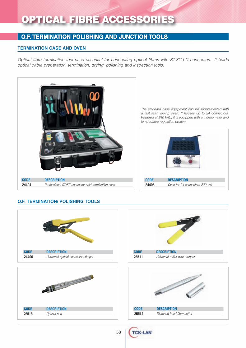
O.F. TERMINATION POLISHING AND JUNCTION TOOLS
Optical fibre termination tool case essential for connecting optical fibres with ST-SC-LC connectors. It holdsoptical cable preparation, termination, drying, polishing and inspection tools.
O.F. TERMINATION/ POLISHING TOOLS
TERMINATION CASE AND OVEN
CODE DESCRIPTION24406 Universal optical connector crimper
CODE DESCRIPTION25511 Universal miller wire stripper
CODE DESCRIPTION25512 Diamond head fibre cutter
CODE DESCRIPTION24405 Oven for 24 connectors 220 volt
The standard case equipment can be supplemented with a fast resin drying oven. It houses up to 24 connectors.Powered at 240 VAC, it is equipped with a thermometer andtemperature regulation system.
CODE DESCRIPTION25515 Optical pen
OPTICAL FIBRE ACCESSORIES
CODE DESCRIPTION24404 Professional ST/SC connector cold termination case
51
O.F. TERMINATION POLISHING AND JUNCTION TOOLS
O.F. TERMINATION/ POLISHING TOOLS
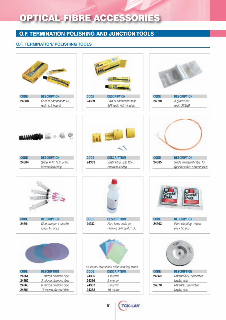
CODE DESCRIPTION24388 Cold bi-component 151
resin (12 hours)
CODE DESCRIPTION24389 Cold bi-component fast
608 resin (10 minutes)
CODE DESCRIPTION24390 4 grams hot
resin 353ND
CODE DESCRIPTION24384 Splitter kit for 12 to 24 O.F.
loose cable heading
CODE DESCRIPTION24383 Splitter kit for up to 12 O.F.
loos cable heading
CODE DESCRIPTION24385 Single immaterial cable for
tight/loose fibre reconstruction
CODE DESCRIPTION24391 Glue syringe + needle
(pack 10 pcs.)
CODE DESCRIPTION24932 Fibre loose cable gel
cleaning detergent (1 LT.)
CODE DESCRIPTION24393 Fibre cleaning wipes
pack 50 pcs
CODE DESCRIPTION24361 1 micron diamond disk24362 3 micron diamond disk24363 6 micron diamond disk24364 15 micron diamond disk
CODE DESCRIPTION24365 1 micron 24366 3 micron 24367 5 micron 24368 15 micron
CODE DESCRIPTION24369 Manual ST/SC connection
lapping plate24370 Manual LC connection
lapping plate
OPTICAL FIBRE ACCESSORIES
A4 format aluminium oxide sanding paper
52
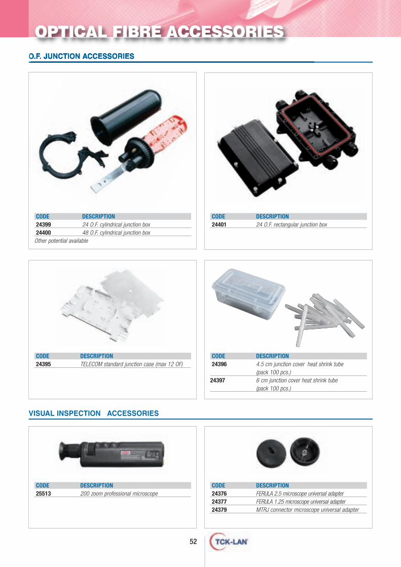
O.F. JUNCTION ACCESSORIES
VISUAL INSPECTION ACCESSORIES
CODE DESCRIPTION24399 24 O.F. cylindrical junction box24400 48 O.F. cylindrical junction box
Other potential available
CODE DESCRIPTION24395 TELECOM standard junction case (max 12 OF)
CODE DESCRIPTION24401 24 O.F. rectangular junction box
CODE DESCRIPTION24396 4.5 cm junction cover heat shrink tube
(pack 100 pcs.)24397 6 cm junction cover heat shrink tube
(pack 100 pcs.)
CODE DESCRIPTION25513 200 zoom professional microscope
CODE DESCRIPTION24376 FERULA 2.5 microscope universal adapter 24377 FERULA 1.25 microscope universal adapter 24379 MTRJ connector microscope universal adapter
OPTICAL FIBRE ACCESSORIES
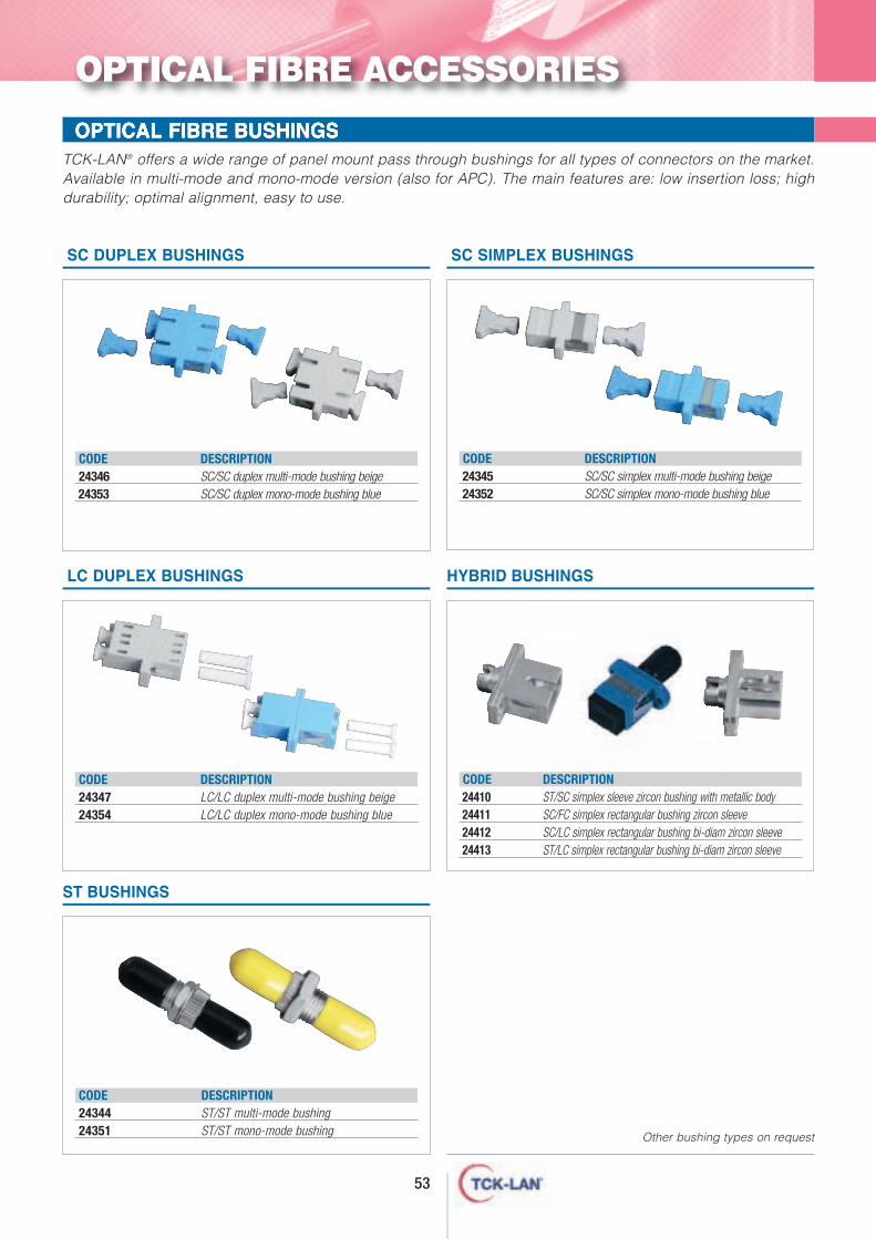
CODE DESCRIPTION24346 SC/SC duplex multi-mode bushing beige24353 SC/SC duplex mono-mode bushing blue
SC DUPLEX BUSHINGS
53
OPTICAL FIBRE BUSHINGSTCK-LAN® offers a wide range of panel mount pass through bushings for all types of connectors on the market.Available in multi-mode and mono-mode version (also for APC). The main features are: low insertion loss; highdurability; optimal alignment, easy to use.
ST BUSHINGS
CODE DESCRIPTION24345 SC/SC simplex multi-mode bushing beige24352 SC/SC simplex mono-mode bushing blue
SC SIMPLEX BUSHINGS
CODE DESCRIPTION24410 ST/SC simplex sleeve zircon bushing with metallic body24411 SC/FC simplex rectangular bushing zircon sleeve24412 SC/LC simplex rectangular bushing bi-diam zircon sleeve24413 ST/LC simplex rectangular bushing bi-diam zircon sleeve
HYBRID BUSHINGS
CODE DESCRIPTION24347 LC/LC duplex multi-mode bushing beige24354 LC/LC duplex mono-mode bushing blue
LC DUPLEX BUSHINGS
OPTICAL FIBRE ACCESSORIES
Other bushing types on request
CODE DESCRIPTION24344 ST/ST multi-mode bushing24351 ST/ST mono-mode bushing
OPTICAL FIBRE CONNECTORSThe wide range of TCK-LAN® connectors offers high product quality to meet the most demanding needs. Multi-modeand mono-mode applications (PC and APC) are available for fibre termination. They are use to create patch cordsand backbone cables (for 2 mm break-out fibre and 900 micro tight) and PIG-TAIL for welded junction.
OPTICAL DIMMERSWhen the optical signal is too intense, devices able to dim their intensity are needed. These devices are called dimmers.Dimmers are available for all types of connectors (multi-mode and mono-mode) with different nominal values.
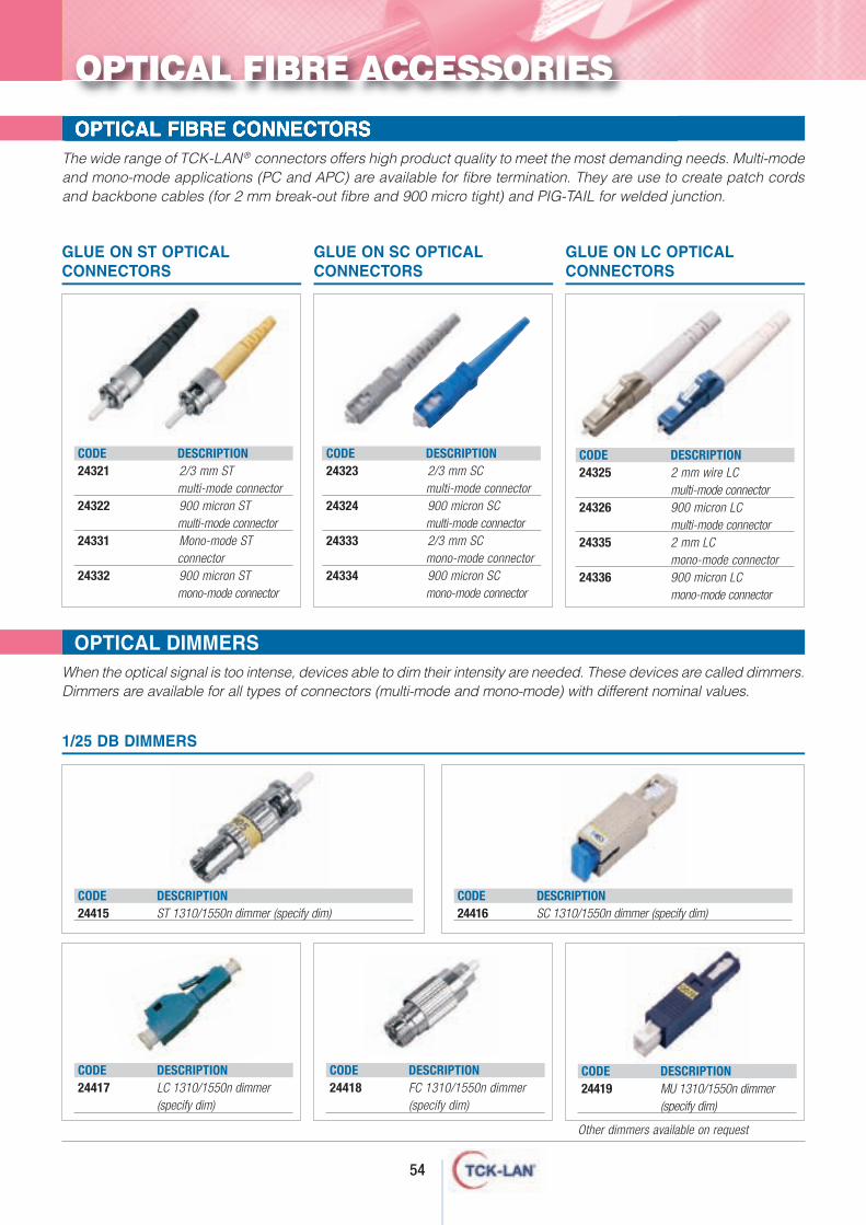
CODE DESCRIPTION24321 2/3 mm ST
multi-mode connector24322 900 micron ST
multi-mode connector24331 Mono-mode ST
connector24332 900 micron ST
mono-mode connector
GLUE ON ST OPTICALCONNECTORS
CODE DESCRIPTION24323 2/3 mm SC
multi-mode connector24324 900 micron SC
multi-mode connector24333 2/3 mm SC
mono-mode connector 24334 900 micron SC
mono-mode connector
GLUE ON SC OPTICALCONNECTORS
CODE DESCRIPTION24325 2 mm wire LC
multi-mode connector24326 900 micron LC
multi-mode connector24335 2 mm LC
mono-mode connector24336 900 micron LC
mono-mode connector
GLUE ON LC OPTICALCONNECTORS
CODE DESCRIPTION24415 ST 1310/1550n dimmer (specify dim)
CODE DESCRIPTION24417 LC 1310/1550n dimmer
(specify dim)
CODE DESCRIPTION24416 SC 1310/1550n dimmer (specify dim)
CODE DESCRIPTION24418 FC 1310/1550n dimmer
(specify dim)
CODE DESCRIPTION24419 MU 1310/1550n dimmer
(specify dim)
Other dimmers available on request
1/25 DB DIMMERS
OPTICAL FIBRE ACCESSORIES
54
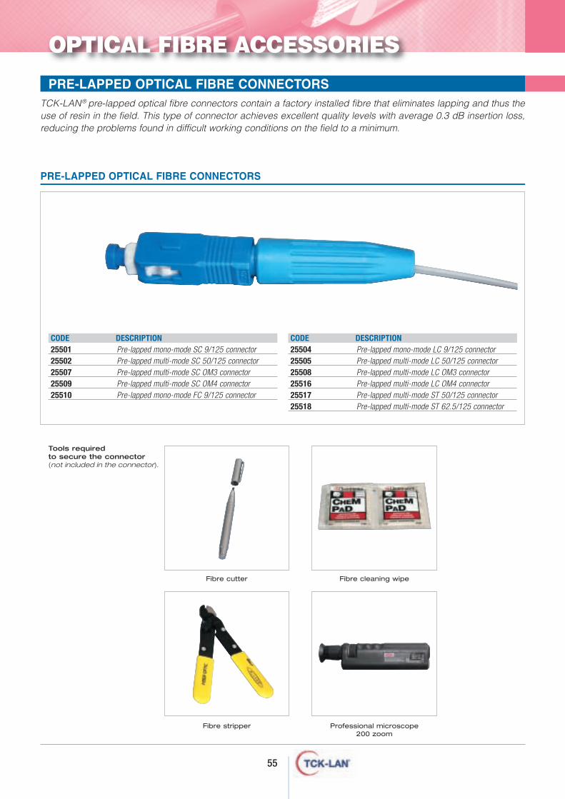
55
TCK-LAN® pre-lapped optical fibre connectors contain a factory installed fibre that eliminates lapping and thus theuse of resin in the field. This type of connector achieves excellent quality levels with average 0.3 dB insertion loss,reducing the problems found in difficult working conditions on the field to a minimum.
PRE-LAPPED OPTICAL FIBRE CONNECTORS
OPTICAL FIBRE ACCESSORIES
PRE-LAPPED OPTICAL FIBRE CONNECTORS
Tools required to secure the connector (not included in the connector).
Fibre cleaning wipe
Fibre stripper
Fibre cutter
Professional microscope200 zoom
CODE DESCRIPTION25501 Pre-lapped mono-mode SC 9/125 connector25502 Pre-lapped multi-mode SC 50/125 connector25507 Pre-lapped multi-mode SC OM3 connector25509 Pre-lapped multi-mode SC OM4 connector25510 Pre-lapped mono-mode FC 9/125 connector
CODE DESCRIPTION25504 Pre-lapped mono-mode LC 9/125 connector25505 Pre-lapped multi-mode LC 50/125 connector25508 Pre-lapped multi-mode LC OM3 connector25516 Pre-lapped multi-mode LC OM4 connector25517 Pre-lapped multi-mode ST 50/125 connector25518 Pre-lapped multi-mode ST 62.5/125 connector
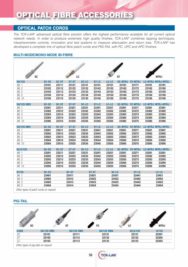
56
OPTICAL PATCH CORDSThe TCK-LAN® advanced optical fibre solution offers the highest performance available for all current opticalnetwork needs. In order to produce extremely high quality finishes, TCK-LAN® combines lapping techniques,interpherometre controls, innovation and test systems to measure attenuation and return loss. TCK-LAN® hasdeveloped a complete line of optical fibre patch cords and PIG-TAIL with PC, UPC and APC finishes.
MULTI-MODE/MONO-MODE BI-FIBRE
CODE 50/125 OM2 50/125 OM3 50/125 OM4 62,5/125 9/125 SCSTLC
Other types of pig-tails on request
22101 22111 22131 22121 2220122102 22112 22132 22122 2220222103 22113 22133 22123 22203
9/125 SC-SC SC-ST ST-ST SC-LC ST-LC LC-LCMt. 1Mt. 2Mt. 3Mt. 5
Other types of patch cords on request
23401 23411 23421 23431 23441 2345123402 23412 23422 23432 23442 2345223403 23413 23423 23433 23443 2345323404 23414 23424 23434 23444 23454
50/125 SC-SC SC-ST ST-ST SC-LC ST-LC LC-LC SC-MTRJ ST-MTRJ LC-MTRJ MTRJ-MTRJMt. 1Mt. 2Mt. 3Mt. 5Mt. 10
23101 23111 23121 23131 23141 23151 23161 23171 23181 2319123102 23112 23122 23132 23142 23152 23162 23172 23182 2319223103 23113 23123 23133 23143 23153 23163 23173 23183 2319323104 23114 23124 23134 23144 23154 23164 23174 23184 2319423105 23115 23125 23135 23145 23155 23165 23175 23185 23195
50/125 OM3 SC-SC SC-ST ST-ST SC-LC ST-LC LC-LC SC-MTRJ ST-MTRJ LC-MTRJ MTRJ-MTRJMt. 1Mt. 2Mt. 3Mt. 5Mt. 10
23301 23311 23321 23331 23341 23351 23361 23371 23381 2339123302 23312 23322 23332 23342 23352 23362 23372 23382 2339223303 23313 23323 23333 23343 23353 23363 23373 23383 2339323304 23314 23324 23334 23344 23354 23364 23374 23384 2339423305 23315 23325 23335 23345 23355 23365 23375 23385 23395
62.5/125 SC-SC SC-ST ST-ST SC-LC ST-LC LC-LC SC-MTRJ ST-MTRJ LC-MTRJ MTRJ-MTRJMt. 1Mt. 2Mt. 3Mt. 5Mt. 10
23201 23211 23221 23231 23241 23251 23261 23271 23281 2329123202 23212 23222 23232 23242 23252 23262 23272 23282 2329223203 23213 23223 23233 23243 23253 23263 23273 23283 2329323204 23214 23224 23234 23244 23254 23264 23274 23284 2329423205 23215 23225 23235 23245 23255 23265 23275 23285 23295
50/125 0M4 SC-SC SC-ST ST-ST SC-LC ST-LC LC-LC SC-MTRJ ST-MTRJ LC-MTRJ MTRJ-MTRJMt. 1Mt. 2Mt. 3Mt. 5Mt. 10
23501 23511 23521 23531 23541 23551 23561 23571 23581 2359123502 23512 23522 23532 23542 23552 23562 23572 23582 2359223503 23513 23523 23533 23543 23553 23563 23573 23583 2359323504 23514 23524 23534 23544 23554 23564 23574 23584 2359423505 23515 23525 23535 23545 23555 23565 23575 23585 23595
PIG-TAIL
SC LC ST MTRJ
SC ST FC LC MTRJ
OPTICAL FIBRE ACCESSORIES
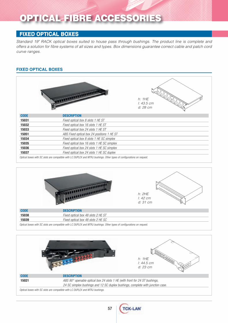
57
FIXED OPTICAL BOXESStandard 19" RACK optical boxes suited to house pass through bushings. The product line is complete andoffers a solution for fibre systems of all sizes and types. Box dimensions guarantee correct cable and patch cordcurve ranges.
CODE DESCRIPTION15031 Fixed optical box 8 slots 1 HE ST15032 Fixed optical box 16 slots 1 HE ST15033 Fixed optical box 24 slots 1 HE ST15051 ABS Fixed optical box 24 positions 1 HE ST 15034 Fixed optical box 8 slots 1 HE SC simplex15035 Fixed optical box 16 slots 1 HE SC simplex15036 Fixed optical box 24 slots 1 HE SC simplex15037 Fixed optical box 24 slots 1 HE SC duplex
Optical boxes with SC slots are compatible with LC DUPLEX and MTRJ bushings. Other types of configurations on request.
FIXED OPTICAL BOXES
CODE DESCRIPTION15038 Fixed optical box 48 slots 2 HE ST15039 Fixed optical box 48 slots 2 HE SC
Optical boxes with SC slots are compatible with LC DUPLEX and MTRJ bushings. Other types of configurations on request.
CODE DESCRIPTION15021 ABS 90° openable optical box 24 slots 1 HE (with front for 24 ST bushings,
24 SC simplex bushings and 12 SC duplex bushings, complete with junction case.Optical boxes with SC slots are compatible with LC DUPLEX and MTRJ bushings.
OPTICAL FIBRE ACCESSORIES
1
2
3
4
5
6
7
8
12
34
56
78
910
1112
1314
1516
1718
1920
2122
2324
2526
2728
2930
3132
3334
3536
3738
3940
4142
4344
4546
4748
h: 2HEl: 42 cmd: 31 cm
h: 1HEl: 43.5 cmd: 28 cm
h: 1HEl: 44.5 cmd: 23 cm
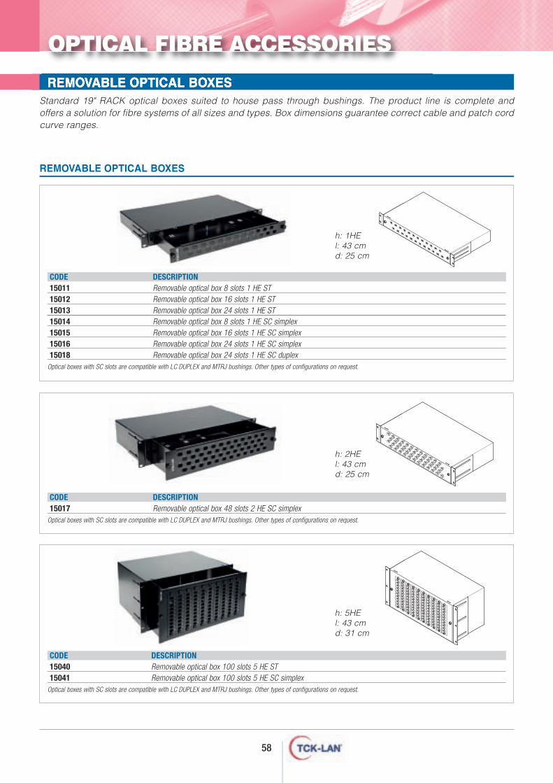
58
REMOVABLE OPTICAL BOXESStandard 19" RACK optical boxes suited to house pass through bushings. The product line is complete andoffers a solution for fibre systems of all sizes and types. Box dimensions guarantee correct cable and patch cordcurve ranges.
CODE DESCRIPTION15011 Removable optical box 8 slots 1 HE ST15012 Removable optical box 16 slots 1 HE ST15013 Removable optical box 24 slots 1 HE ST15014 Removable optical box 8 slots 1 HE SC simplex15015 Removable optical box 16 slots 1 HE SC simplex15016 Removable optical box 24 slots 1 HE SC simplex15018 Removable optical box 24 slots 1 HE SC duplex
Optical boxes with SC slots are compatible with LC DUPLEX and MTRJ bushings. Other types of configurations on request.
REMOVABLE OPTICAL BOXES
CODE DESCRIPTION15017 Removable optical box 48 slots 2 HE SC simplex
Optical boxes with SC slots are compatible with LC DUPLEX and MTRJ bushings. Other types of configurations on request.
CODE DESCRIPTION15040 Removable optical box 100 slots 5 HE ST15041 Removable optical box 100 slots 5 HE SC simplex
Optical boxes with SC slots are compatible with LC DUPLEX and MTRJ bushings. Other types of configurations on request.
OPTICAL FIBRE ACCESSORIES
h: 1HEl: 43 cmd: 25 cm
h: 2HEl: 43 cmd: 25 cm
h: 5HEl: 43 cmd: 31 cm
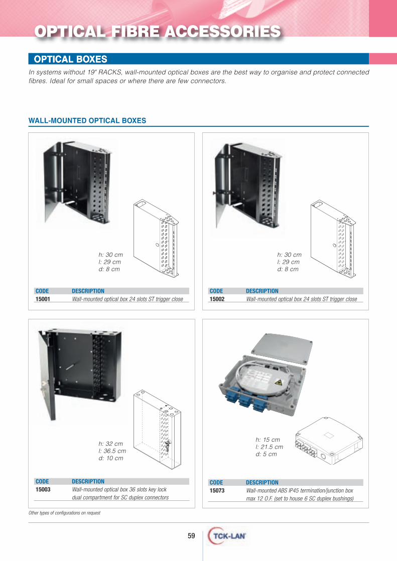
59
In systems without 19" RACKS, wall-mounted optical boxes are the best way to organise and protect connectedfibres. Ideal for small spaces or where there are few connectors.
WALL-MOUNTED OPTICAL BOXES
OPTICAL BOXES
CODE DESCRIPTION15001 Wall-mounted optical box 24 slots ST trigger close
CODE DESCRIPTION15002 Wall-mounted optical box 24 slots ST trigger close
CODE DESCRIPTION15073 Wall-mounted ABS IP45 termination/junction box
max 12 O.F. (set to house 6 SC duplex bushings)
CODE DESCRIPTION15003 Wall-mounted optical box 36 slots key lock
dual compartment for SC duplex connectors
Other types of configurations on request
OPTICAL FIBRE ACCESSORIES
h: 30 cml: 29 cmd: 8 cm
h: 30 cml: 29 cmd: 8 cm
h: 32 cml: 36.5 cmd: 10 cm
h: 15 cml: 21.5 cmd: 5 cm
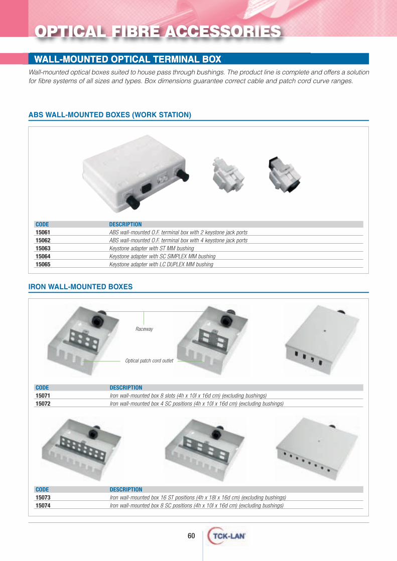
60
WALL-MOUNTED OPTICAL TERMINAL BOXWall-mounted optical boxes suited to house pass through bushings. The product line is complete and offers a solutionfor fibre systems of all sizes and types. Box dimensions guarantee correct cable and patch cord curve ranges.
CODE DESCRIPTION15061 ABS wall-mounted O.F. terminal box with 2 keystone jack ports15062 ABS wall-mounted O.F. terminal box with 4 keystone jack ports15063 Keystone adapter with ST MM bushing15064 Keystone adapter with SC SIMPLEX MM bushing15065 Keystone adapter with LC DUPLEX MM bushing
ABS WALL-MOUNTED BOXES (WORK STATION)
CODE DESCRIPTION15071 Iron wall-mounted box 8 slots (4h x 10I x 16d cm) (excluding bushings)15072 Iron wall-mounted box 4 SC positions (4h x 10I x 16d cm) (excluding bushings)
CODE DESCRIPTION15073 Iron wall-mounted box 16 ST positions (4h x 18I x 16d cm) (excluding bushings)15074 Iron wall-mounted box 8 SC positions (4h x 10I x 16d cm) (excluding bushings)
IRON WALL-MOUNTED BOXES
OPTICAL FIBRE ACCESSORIES
Raceway
Optical patch cord outlet
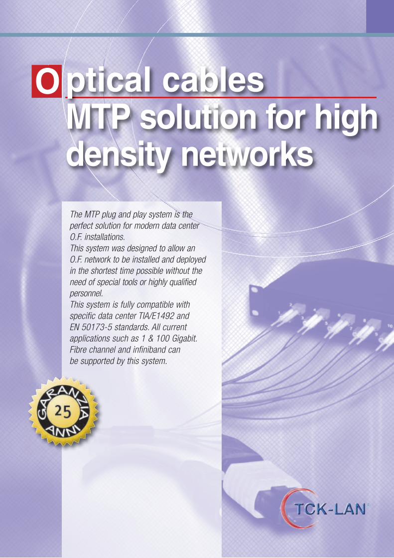
ptical cablesMTP solution for highdensity networks
O
The MTP plug and play system is theperfect solution for modern data center O.F. installations.This system was designed to allow an O.F. network to be installed and deployed in the shortest time possible without theneed of special tools or highly qualifiedpersonnel.This system is fully compatible withspecific data center TIA/E1492 and EN 50173-5 standards. All currentapplications such as 1 & 100 Gigabit.Fibre channel and infiniband can be supported by this system.
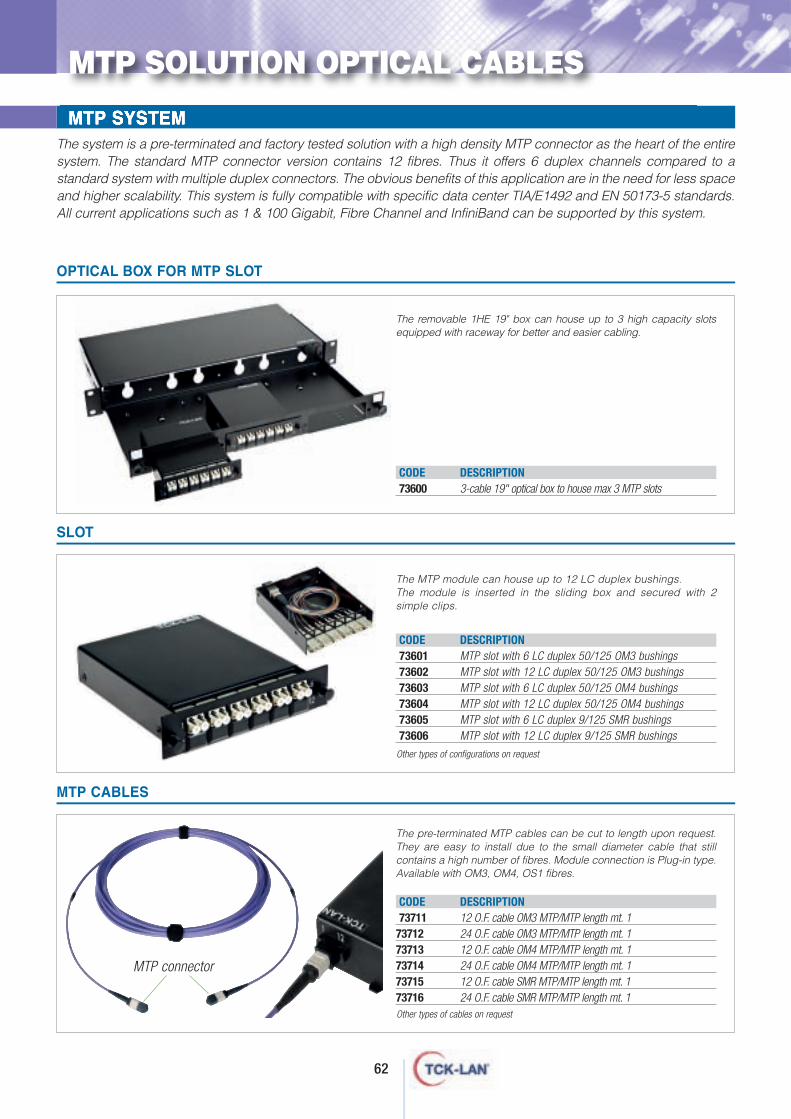
MTP SYSTEMThe system is a pre-terminated and factory tested solution with a high density MTP connector as the heart of the entiresystem. The standard MTP connector version contains 12 fibres. Thus it offers 6 duplex channels compared to astandard system with multiple duplex connectors. The obvious benefits of this application are in the need for less spaceand higher scalability. This system is fully compatible with specific data center TIA/E1492 and EN 50173-5 standards.All current applications such as 1 & 100 Gigabit, Fibre Channel and InfiniBand can be supported by this system.
MTP SOLUTION OPTICAL CABLES
The pre-terminated MTP cables can be cut to length upon request.They are easy to install due to the small diameter cable that stillcontains a high number of fibres. Module connection is Plug-in type.Available with OM3, OM4, OS1 fibres.
The MTP module can house up to 12 LC duplex bushings.The module is inserted in the sliding box and secured with 2simple clips.
The removable 1HE 19" box can house up to 3 high capacity slotsequipped with raceway for better and easier cabling.
OPTICAL BOX FOR MTP SLOT
SLOT
MTP CABLES
62
CODE DESCRIPTION73600 3-cable 19" optical box to house max 3 MTP slots
CODE DESCRIPTION73601 MTP slot with 6 LC duplex 50/125 OM3 bushings73602 MTP slot with 12 LC duplex 50/125 OM3 bushings73603 MTP slot with 6 LC duplex 50/125 OM4 bushings73604 MTP slot with 12 LC duplex 50/125 OM4 bushings73605 MTP slot with 6 LC duplex 9/125 SMR bushings73606 MTP slot with 12 LC duplex 9/125 SMR bushings
CODE DESCRIPTION73711 12 O.F. cable OM3 MTP/MTP length mt. 1
73712 24 O.F. cable OM3 MTP/MTP length mt. 173713 12 O.F. cable OM4 MTP/MTP length mt. 173714 24 O.F. cable OM4 MTP/MTP length mt. 173715 12 O.F. cable SMR MTP/MTP length mt. 173716 24 O.F. cable SMR MTP/MTP length mt. 1
Other types of configurations on request
Other types of cables on request
MTP connector
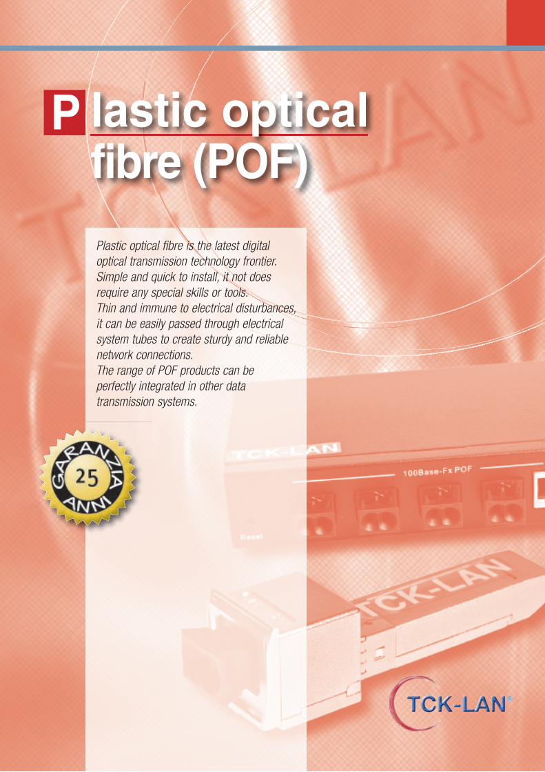
lastic optical fibre (POF)
P
Plastic optical fibre is the latest digitaloptical transmission technology frontier.Simple and quick to install, it not doesrequire any special skills or tools. Thin and immune to electrical disturbances,it can be easily passed through electricalsystem tubes to create sturdy and reliablenetwork connections. The range of POF products can be perfectly integrated in other datatransmission systems.
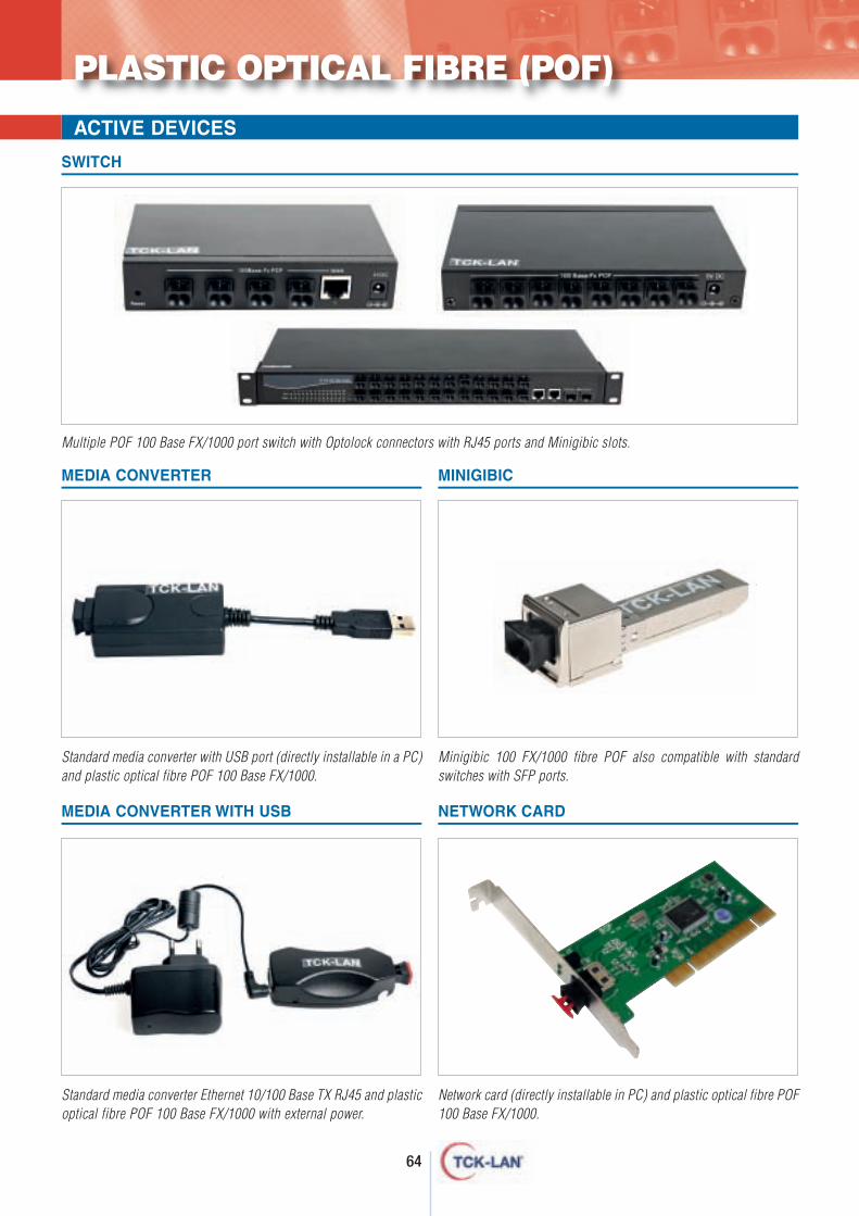
64
PLASTIC OPTICAL FIBRE (POF)
ACTIVE DEVICES
Standard media converter Ethernet 10/100 Base TX RJ45 and plasticoptical fibre POF 100 Base FX/1000 with external power.
Standard media converter with USB port (directly installable in a PC)and plastic optical fibre POF 100 Base FX/1000.
Multiple POF 100 Base FX/1000 port switch with Optolock connectors with RJ45 ports and Minigibic slots.
Network card (directly installable in PC) and plastic optical fibre POF100 Base FX/1000.
Minigibic 100 FX/1000 fibre POF also compatible with standardswitches with SFP ports.
SWITCH
MEDIA CONVERTER MINIGIBIC
MEDIA CONVERTER WITH USB NETWORK CARD
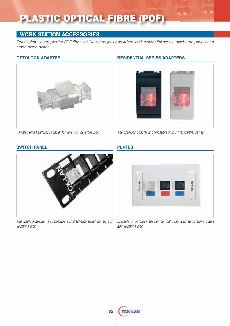
65
WORK STATION ACCESSORIES
PLASTIC OPTICAL FIBRE (POF)
OPTOLOCK ADAPTER RESIDENTIAL SERIES ADAPTERS
SWITCH PANEL PLATES
Female/female adapter for POF fibre with Keystone jack can adapt to all residential series, discharge panels andstand alone plates.
Female/Female Optolock adapter for fibre POF Keystone jack. The optolock adapter is compatible with all residential series.
The optolock adapter is compatible with discharge switch panels withkeystone jack.
Example of optolock adapter compatibility with stand alone platesand keystone jack.
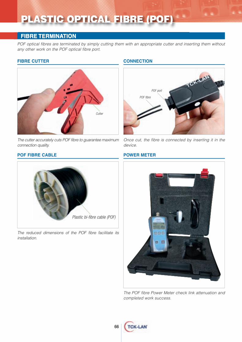
66
FIBRE TERMINATIONPOF optical fibres are terminated by simply cutting them with an appropriate cutter and inserting them withoutany other work on the POF optical fibre port.
The POF fibre Power Meter check link attenuation andcompleted work success.
PLASTIC OPTICAL FIBRE (POF)
Cutter
POF port
Plastic bi-fibre cable (POF)
POWER METERPOF FIBRE CABLE
FIBRE CUTTER CONNECTION
The cutter accurately cuts POF fibre to guarantee maximumconnection quality.
The reduced dimensions of the POF fibre facilitate itsinstallation.
Once cut, the fibre is connected by inserting it in thedevice.
POF fibre
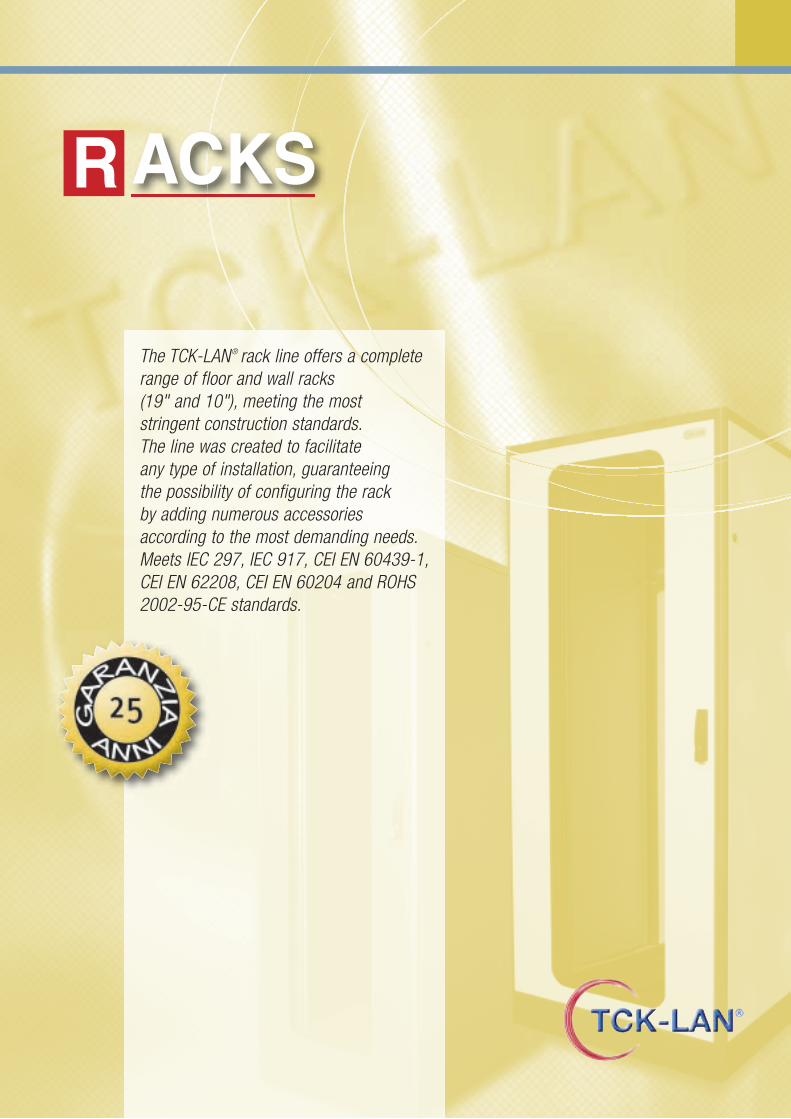
ACKSR
The TCK-LAN® rack line offers a completerange of floor and wall racks (19" and 10"), meeting the most stringent construction standards. The line was created to facilitate any type of installation, guaranteeing the possibility of configuring the rack by adding numerous accessoriesaccording to the most demanding needs. Meets IEC 297, IEC 917, CEI EN 60439-1,CEI EN 62208, CEI EN 60204 and ROHS2002-95-CE standards.
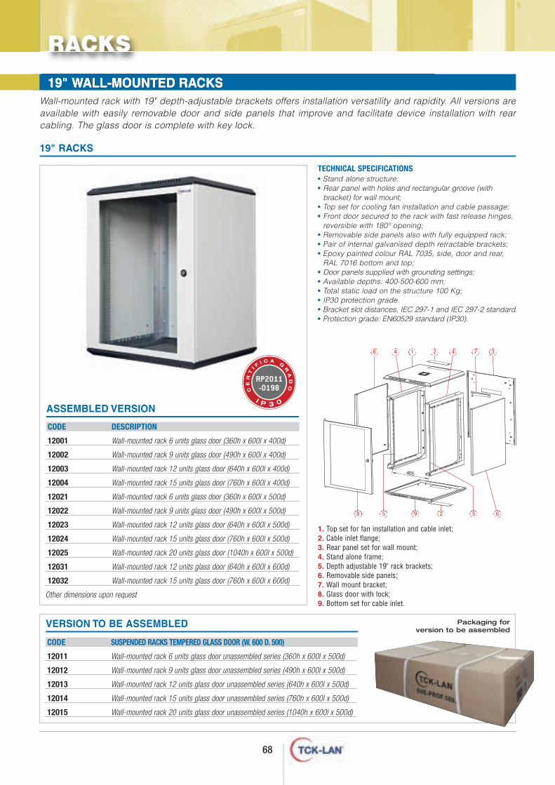
68
WALL-MOUNTED RACKS Wall-mounted rack with 19" depth-adjustable brackets offers installation versatility and rapidity. All versions areavailable with easily removable door and side panels that improve and facilitate device installation with rearcabling. The glass door is complete with key lock.
CODE DESCRIPTION
12001 Wall-mounted rack 6 units glass door (360h x 600l x 400d)
12002 Wall-mounted rack 9 units glass door (490h x 600l x 400d)
12003 Wall-mounted rack 12 units glass door (640h x 600l x 400d)
12004 Wall-mounted rack 15 units glass door (760h x 600l x 400d)
12021 Wall-mounted rack 6 units glass door (360h x 600l x 500d)
12022 Wall-mounted rack 9 units glass door (490h x 600l x 500d)
12023 Wall-mounted rack 12 units glass door (640h x 600l x 500d)
12024 Wall-mounted rack 15 units glass door (760h x 600l x 500d)
12025 Wall-mounted rack 20 units glass door (1040h x 600l x 500d)
12031 Wall-mounted rack 12 units glass door (640h x 600l x 600d)
12032 Wall-mounted rack 15 units glass door (760h x 600l x 600d)
Other dimensions upon request
WALL-MOUNTED RACKS 19" WALL-MOUNTED RACKS
• Stand alone structure;• Rear panel with holes and rectangular groove (with
bracket) for wall mount;• Top set for cooling fan installation and cable passage;• Front door secured to the rack with fast release hinges,
reversible with 180° opening;• Removable side panels also with fully equipped rack;• Pair of internal galvanised depth retractable brackets;• Epoxy painted colour RAL 7035, side, door and rear,
RAL 7016 bottom and top;• Door panels supplied with grounding settings;• Available depths: 400-500-600 mm;• Total static load on the structure 100 Kg;• IP30 protection grade.• Bracket slot distances, IEC 297-1 and IEC 297-2 standard.• Protection grade: EN60529 standard (IP30).
1. Top set for fan installation and cable inlet;2. Cable inlet flange;3. Rear panel set for wall mount;4. Stand alone frame;5. Depth adjustable 19" rack brackets;6. Removable side panels; 7. Wall mount bracket; 8. Glass door with lock; 9. Bottom set for cable inlet.
TECHNICAL SPECIFICATIONS
19" RACKS
ASSEMBLED VERSION
RACKS
VERSION TO BE ASSEMBLED
CODE SUSPENDED RACKS TEMPERED GLASS DOOR (W. 600 D. 500)
12011 Wall-mounted rack 6 units glass door unassembled series (360h x 600l x 500d)
12012 Wall-mounted rack 9 units glass door unassembled series (490h x 600l x 500d)
12013 Wall-mounted rack 12 units glass door unassembled series (640h x 600l x 500d)
12014 Wall-mounted rack 15 units glass door unassembled series (760h x 600l x 500d)
12015 Wall-mounted rack 20 units glass door unassembled series (1040h x 600l x 500d)
Packaging for version to be assembled
6 4 1 2 4 7 3
8 5 9 2 5 6
RP2011-0198C
ER
TI F
I C A G
RA
DO
I P 3 0
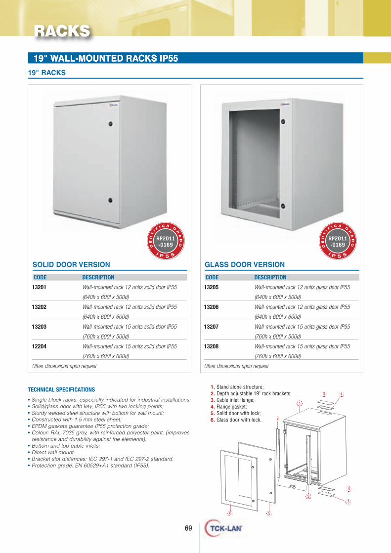
69
• Single block racks, especially indicated for industrial installations;• Solid/glass door with key, IP55 with two locking points;• Sturdy welded steel structure with bottom for wall mount;• Constructed with 1.5 mm steel sheet;• EPDM gaskets guarantee IP55 protection grade;• Colour: RAL 7035 grey, with reinforced polyester paint, (improves
resistance and durability against the elements);• Bottom and top cable inlets;• Direct wall mount.• Bracket slot distances: IEC 297-1 and IEC 297-2 standard.• Protection grade: EN 60529+A1 standard (IP55).
TECHNICAL SPECIFICATIONS
19" WALL-MOUNTED RACKS IP55
RACKS
CODE DESCRIPTION
13201 Wall-mounted rack 12 units solid door IP55
(640h x 600l x 500d)
13202 Wall-mounted rack 12 units solid door IP55
(640h x 600l x 600d)
13203 Wall-mounted rack 15 units solid door IP55
(760h x 600l x 500d)
12204 Wall-mounted rack 15 units solid door IP55
(760h x 600l x 600d)
Other dimensions upon request
19" RACKS
SOLID DOOR VERSION
CODE DESCRIPTION
13205 Wall-mounted rack 12 units glass door IP55
(640h x 600l x 500d)
13206 Wall-mounted rack 12 units glass door IP55
(640h x 600l x 600d)
13207 Wall-mounted rack 15 units glass door IP55
(760h x 600l x 500d)
13208 Wall-mounted rack 15 units glass door IP55
(760h x 600l x 600d)
Other dimensions upon request
GLASS DOOR VERSION
1. Stand alone structure;2. Depth adjustable 19" rack brackets;3. Cable inlet flange;4. Flange gasket;5. Solid door with lock;6. Glass door with lock.
6 5
23
4
43
1
2
RP2011-0169C
ER
TI F
I C A G
RA
DO
I P 5 5
RP2011-0169C
ER
TI F
I C A G
RA
DO
I P 5 5
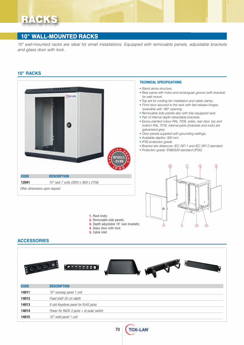
70
WALL-MOUNTED RACKS WALL-MOUNTED RACKS 10" WALL-MOUNTED RACKS
RACKS
1. Rack body;2. Removable side panels;3. Depth adjustable 10" rack brackets;4. Glass door with lock;5. Cable inlet.
CODE DESCRIPTION
12041 10" rack 7 units (385h x 360l x 270d)
Other dimensions upon request
• Stand alone structure;• Rear panel with holes and rectangular groove (with bracket)
for wall mount;• Top set for cooling fan installation and cable clamp;• Front door secured to the rack with fast release hinges,
reversible with 180° opening;• Removable side panels also with fully equipped rack;• Pair of internal depth retractable brackets;• Epoxy painted colour RAL 7035, sides, rear door, top and
bottom RAL 7016, internal parts (brackets and rods) aregalvanised grey;
• Door panels supplied with grounding settings;• Available depths: 300 mm;• IP30 protection grade.• Bracket slot distances: IEC 297-1 and IEC 297-2 standard.• Protection grade: EN60529 standard (IP30).
TECHNICAL SPECIFICATIONS
10" RACKS
ACCESSORIES
CODE DESCRIPTION
14011 10" raceway panel 1 unit
14012 Fixed shelf 20 cm depth
14013 8 slot Keystone panel for RJ45 jacks
14014 Power for RACK 3 jacks + bi-polar switch
14015 10" solid panel 1 unit
10" wall-mounted racks are ideal for small installations. Equipped with removable panels, adjustable bracketsand glass door with lock.
2 1 5 2
4 3 3 5
RP2011-0198C
ER
TI F
I C A G
RA
DO
I P 3 0
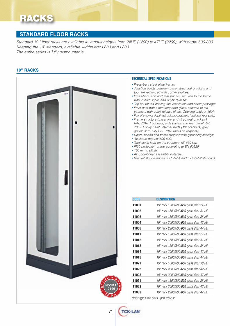
71
RACKS
WALL-MOUNTED RACKS WALL-MOUNTED RACKS STANDARD FLOOR RACKS Standard 19 " floor racks are available in various heights from 24HE (1200) to 47HE (2200), with depth 600-800.Keeping the 19" standard, available widths are: L600 and L800. The entire series is fully dismountable.
• Press-bent steel plate frame;• Junction points between base, structural brackets and
top, are reinforced with corner profiles;• Press-bent side and rear panels, secured to the frame
with 2 "coin" locks and quick release;• Top set for 2/4 cooling fan installation and cable passage;• Front door with 4 mm tempered glass, secured to the
structure with quick release hinge. Opening angle > 150°;• Pair of internal depth retractable brackets (optional rear pair);• Frame structure (base, top and structural brackets)
RAL 7016, front door, side panels and rear panel RAL7035. Epoxy paint, internal parts (19" brackets) greygalvanised (fully RAL 7016 racks on request);
• Doors, panels and frame supplied with grounding settings;• Available depths: 600-800;• Total static load on the structure 19" 650 Kg;• IP30 protection grade according to EN 60529:• 100 mm h plinth.• Air conditioner assembly potential.• Bracket slot distances: IEC 297-1 and IEC 297-2 standard.
TECHNICAL SPECIFICATIONS
19" RACKS
CODE DESCRIPTION
11001 19" rack 1200/600/600 glass door 24 HE
11002 19" rack 1500/600/600 glass door 31 HE
11003 19" rack 1800/600/600 glass door 38 HE
11004 19" rack 2000/600/600 glass door 42 HE
11005 19" rack 2200/600/600 glass door 47 HE
11011 19" rack 1200/600/800 glass door 24 HE
11012 19" rack 1500/600/800 glass door 31 HE
11013 19" rack 1800/600/800 glass door 38 HE
11014 19" rack 2000/600/800 glass door 42 HE
11015 19" rack 2200/600/800 glass door 47 HE
11021 19" rack 1800/800/600 glass door 38 HE
11022 19" rack 2000/800/600 glass door 42 HE
11023 19" rack 2200/800/600 glass door 47 HE
11031 19" rack 1800/800/800 glass door 38 HE
11032 19" rack 2000/800/800 glass door 42 HE
11033 19" rack 2200/800/800 glass door 47 HE
Other types and sizes upon request
RP2011-0199C
ER
TI F
I C A G
RA
DO
I P 3 0
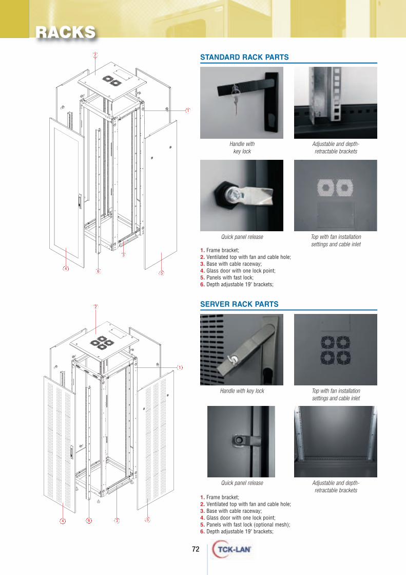
72
RACKS
1. Frame bracket;2. Ventilated top with fan and cable hole;3. Base with cable raceway;4. Glass door with one lock point;5. Panels with fast lock;6. Depth adjustable 19" brackets;
2
1
6
3
45
1. Frame bracket;2. Ventilated top with fan and cable hole;3. Base with cable raceway;4. Glass door with one lock point;5. Panels with fast lock (optional mesh);6. Depth adjustable 19" brackets;
2
1
6 34 5
Handle with key lock
Adjustable and depth- retractable brackets
Quick panel release Top with fan installationsettings and cable inlet
Handle with key lock Top with fan installationsettings and cable inlet
Quick panel release Adjustable and depth- retractable brackets
SERVER RACK PARTS
STANDARD RACK PARTS
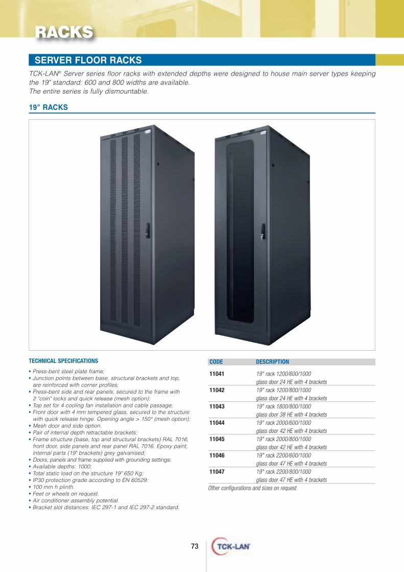
73
RACKS
WALL-MOUNTED RACKS WALL-MOUNTED RACKS SERVER FLOOR RACKS TCK-LAN® Server series floor racks with extended depths were designed to house main server types keepingthe 19" standard: 600 and 800 widths are available. The entire series is fully dismountable.
• Press-bent steel plate frame;• Junction points between base, structural brackets and top,
are reinforced with corner profiles;• Press-bent side and rear panels, secured to the frame with
2 "coin" locks and quick release (mesh option);• Top set for 4 cooling fan installation and cable passage;• Front door with 4 mm tempered glass, secured to the structure
with quick release hinge. Opening angle > 150° (mesh option);• Mesh door and side option.• Pair of internal depth retractable brackets;• Frame structure (base, top and structural brackets) RAL 7016,
front door, side panels and rear panel RAL 7016. Epoxy paint,internal parts (19" brackets) grey galvanised;
• Doors, panels and frame supplied with grounding settings;• Available depths: 1000;• Total static load on the structure 19" 650 Kg;• IP30 protection grade according to EN 60529:• 100 mm h plinth.• Feet or wheels on request.• Air conditioner assembly potential.• Bracket slot distances: IEC 297-1 and IEC 297-2 standard.
CODE DESCRIPTION
11041 19" rack 1200/600/1000 glass door 24 HE with 4 brackets
11042 19" rack 1200/800/1000 glass door 24 HE with 4 brackets
11043 19" rack 1800/800/1000 glass door 38 HE with 4 brackets
11044 19" rack 2000/600/1000 glass door 42 HE with 4 brackets
11045 19" rack 2000/800/1000 glass door 42 HE with 4 brackets
11046 19" rack 2200/600/1000 glass door 47 HE with 4 brackets
11047 19" rack 2200/800/1000 glass door 47 HE with 4 brackets
Other configurations and sizes on request
TECHNICAL SPECIFICATIONS
19" RACKS
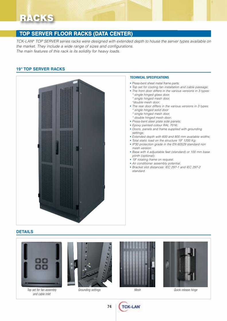
74
WALL-MOUNTED RACKS TCK-LAN® TOP SERVER series racks were designed with extended depth to house the server types available onthe market. They include a wide range of sizes and configurations. The main features of this rack is its solidity for heavy loads.
WALL-MOUNTED RACKS TOP SERVER FLOOR RACKS (DATA CENTER)
• Press-bent sheet metal frame parts;• Top set for cooling fan installation and cable passage;• The front door differs in the various versions in 3 types:
* single hinged glass door,* single hinged mesh door,*double mesh door;
• The rear door differs in the various versions in 3 types:* single hinged solid door* single hinged mesh door,* double hinged mesh door;
• Press-bent steel plate side panels;• Epoxy painted colour RAL 7016;• Doors, panels and frame supplied with grounding
settings;• Extended depth with 600 and 800 mm available widths;• Total static load on the structure 19" 1200 Kg;• IP30 protection grade in the EN 60529 standard non
mesh version:• Base with 4 adjustable feet (standard) or 100 mm base
plinth (optional);• 19" rotating frame on request.• Air conditioner assembly potential.• Bracket slot distances: IEC 297-1 and IEC 297-2
standard.
TECHNICAL SPECIFICATIONS
19" TOP SERVER RACKS
RACKS
DETAILS
Top set for fan assembly and cable inlet
Grounding settings Mesh Quick release hinge
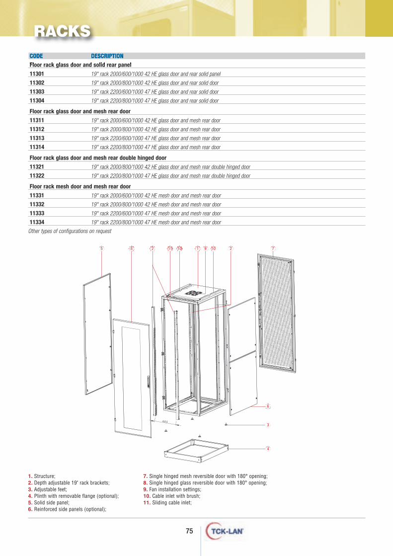
75
CODE DESCRIPTION
Floor rack glass door and solid rear panel
11301
11302
11303
11304
Floor rack glass door and mesh rear door
11311
11312
11313
11314
Floor rack glass door and mesh rear double hinged door
11321
11322
Floor rack mesh door and mesh rear door
11331
11332
11333
11334
Other types of configurations on request
19" rack 2000/600/1000 42 HE glass door and rear solid panel
19" rack 2000/800/1000 42 HE glass door and rear solid door
19" rack 2200/600/1000 47 HE glass door and rear solid door
19" rack 2200/800/1000 47 HE glass door and rear solid door
19" rack 2000/600/1000 42 HE glass door and mesh rear door
19" rack 2000/800/1000 42 HE glass door and mesh rear door
19" rack 2200/600/1000 47 HE glass door and mesh rear door
19" rack 2200/800/1000 47 HE glass door and mesh rear door
19" rack 2000/800/1000 42 HE glass door and mesh rear double hinged door
19" rack 2200/800/1000 47 HE glass door and mesh rear double hinged door
19" rack 2000/600/1000 42 HE mesh door and mesh rear door
19" rack 2000/800/1000 42 HE mesh door and mesh rear door
19" rack 2200/600/1000 47 HE mesh door and mesh rear door
19" rack 2200/800/1000 47 HE mesh door and mesh rear door
RACKS
465
1. Structure;2. Depth adjustable 19" rack brackets;3. Adjustable feet;4. Plinth with removable flange (optional);5. Solid side panel;6. Reinforced side panels (optional);
7. Single hinged mesh reversible door with 180° opening;8. Single hinged glass reversible door with 180° opening;9. Fan installation settings;10. Cable inlet with brush;11. Sliding cable inlet;
5 8 2 10 1 9 10 2 7
6
3
4
11
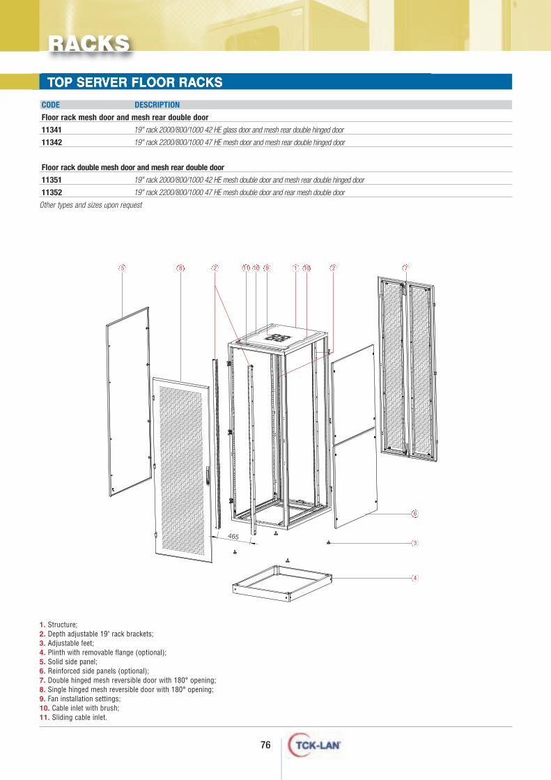
76
TOP SERVER FLOOR RACKS
CODE DESCRIPTION
Floor rack mesh door and mesh rear double door
11341
11342
Floor rack double mesh door and mesh rear double door
11351
11352
Other types and sizes upon request
19" rack 2000/800/1000 42 HE glass door and mesh rear double hinged door
19" rack 2200/800/1000 47 HE mesh door and mesh rear double hinged door
19" rack 2000/800/1000 42 HE mesh double door and mesh rear double hinged door
19" rack 2200/800/1000 47 HE mesh double door and rear mesh double door
RACKS
1. Structure;2. Depth adjustable 19" rack brackets;3. Adjustable feet; 4. Plinth with removable flange (optional);5. Solid side panel; 6. Reinforced side panels (optional);7. Double hinged mesh reversible door with 180° opening;8. Single hinged mesh reversible door with 180° opening; 9. Fan installation settings;10. Cable inlet with brush;11. Sliding cable inlet.
465
5 8 2 10 9 1 10 2 7
6
3
4
11
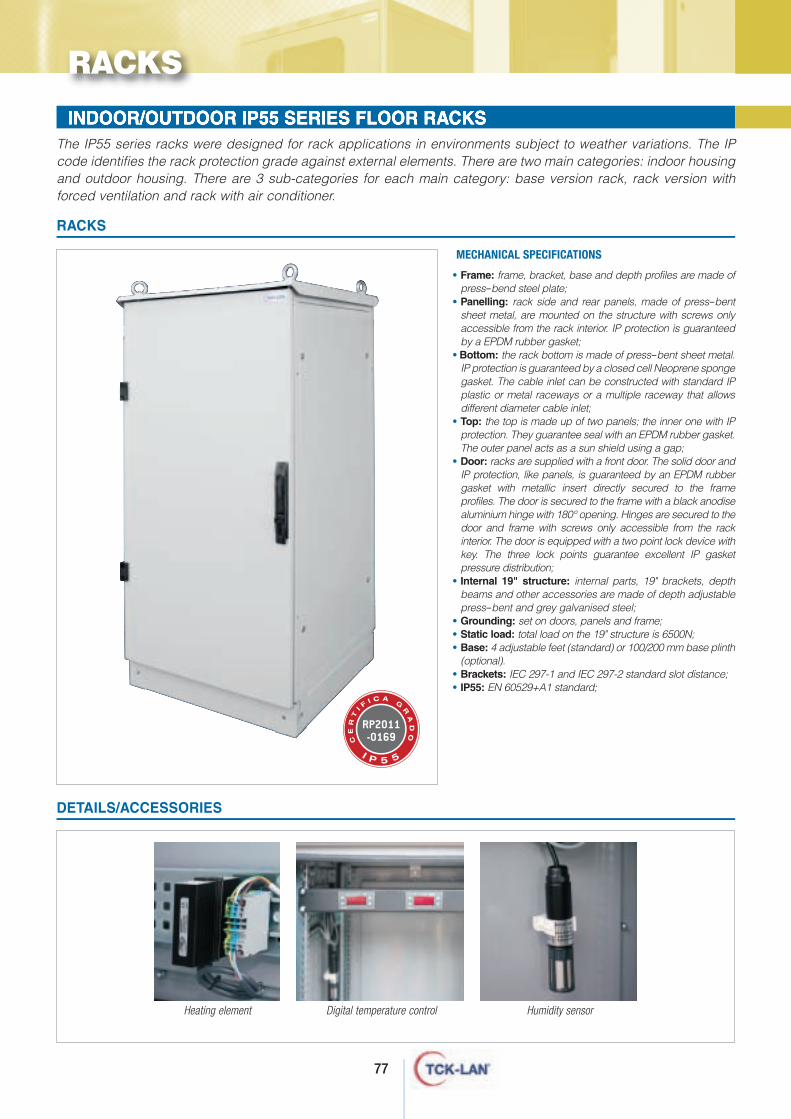
77
INDOOR/OUTDOOR IP55 SERIES FLOOR RACKSThe IP55 series racks were designed for rack applications in environments subject to weather variations. The IPcode identifies the rack protection grade against external elements. There are two main categories: indoor housingand outdoor housing. There are 3 sub-categories for each main category: base version rack, rack version withforced ventilation and rack with air conditioner.
• Frame: frame, bracket, base and depth profiles are made ofpress-bend steel plate;
• Panelling: rack side and rear panels, made of press-bentsheet metal, are mounted on the structure with screws onlyaccessible from the rack interior. IP protection is guaranteedby a EPDM rubber gasket;
• Bottom: the rack bottom is made of press-bent sheet metal.IP protection is guaranteed by a closed cell Neoprene spongegasket. The cable inlet can be constructed with standard IPplastic or metal raceways or a multiple raceway that allowsdifferent diameter cable inlet;
• Top: the top is made up of two panels; the inner one with IPprotection. They guarantee seal with an EPDM rubber gasket.The outer panel acts as a sun shield using a gap;
• Door: racks are supplied with a front door. The solid door andIP protection, like panels, is guaranteed by an EPDM rubbergasket with metallic insert directly secured to the frameprofiles. The door is secured to the frame with a black anodisealuminium hinge with 180° opening. Hinges are secured to thedoor and frame with screws only accessible from the rackinterior. The door is equipped with a two point lock device withkey. The three lock points guarantee excellent IP gasketpressure distribution;
• Internal 19" structure: internal parts, 19" brackets, depthbeams and other accessories are made of depth adjustablepress-bent and grey galvanised steel;
• Grounding: set on doors, panels and frame;• Static load: total load on the 19" structure is 6500N;• Base: 4 adjustable feet (standard) or 100/200 mm base plinth
(optional).• Brackets: IEC 297-1 and IEC 297-2 standard slot distance;• IP55: EN 60529+A1 standard;
MECHANICAL SPECIFICATIONS
RACKS
DETAILS/ACCESSORIES
Heating element Digital temperature control Humidity sensor
RACKS
RP2011-0169C
ER
TI F
I C A G
RA
DO
I P 5 5
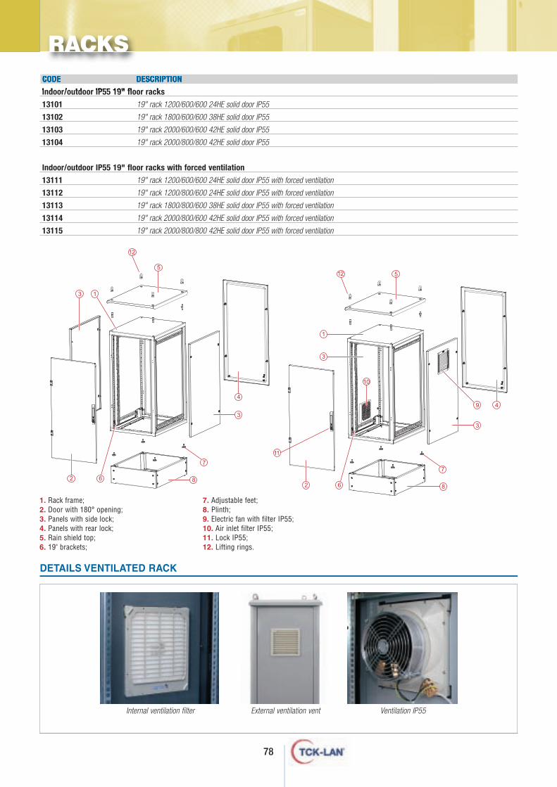
78
CODE DESCRIPTION
Indoor/outdoor IP55 19" floor racks
13101
13102
13103
13104
Indoor/outdoor IP55 19" floor racks with forced ventilation
13111
13112
13113
13114
13115
19" rack 1200/600/600 24HE solid door IP55
19" rack 1800/600/600 38HE solid door IP55
19" rack 2000/600/600 42HE solid door IP55
19" rack 2000/800/800 42HE solid door IP55
19" rack 1200/600/600 24HE solid door IP55 with forced ventilation
19" rack 1200/800/600 24HE solid door IP55 with forced ventilation
19" rack 1800/800/600 38HE solid door IP55 with forced ventilation
19" rack 2000/800/600 42HE solid door IP55 with forced ventilation
19" rack 2000/800/800 42HE solid door IP55 with forced ventilation
DETAILS VENTILATED RACK
Internal ventilation filter External ventilation vent Ventilation IP55
RACKS
12
12
11
1. Rack frame;2. Door with 180° opening;3. Panels with side lock;4. Panels with rear lock;5. Rain shield top;6. 19" brackets;
7. Adjustable feet;8. Plinth; 9. Electric fan with filter IP55; 10. Air inlet filter IP55; 11. Lock IP55; 12. Lifting rings.
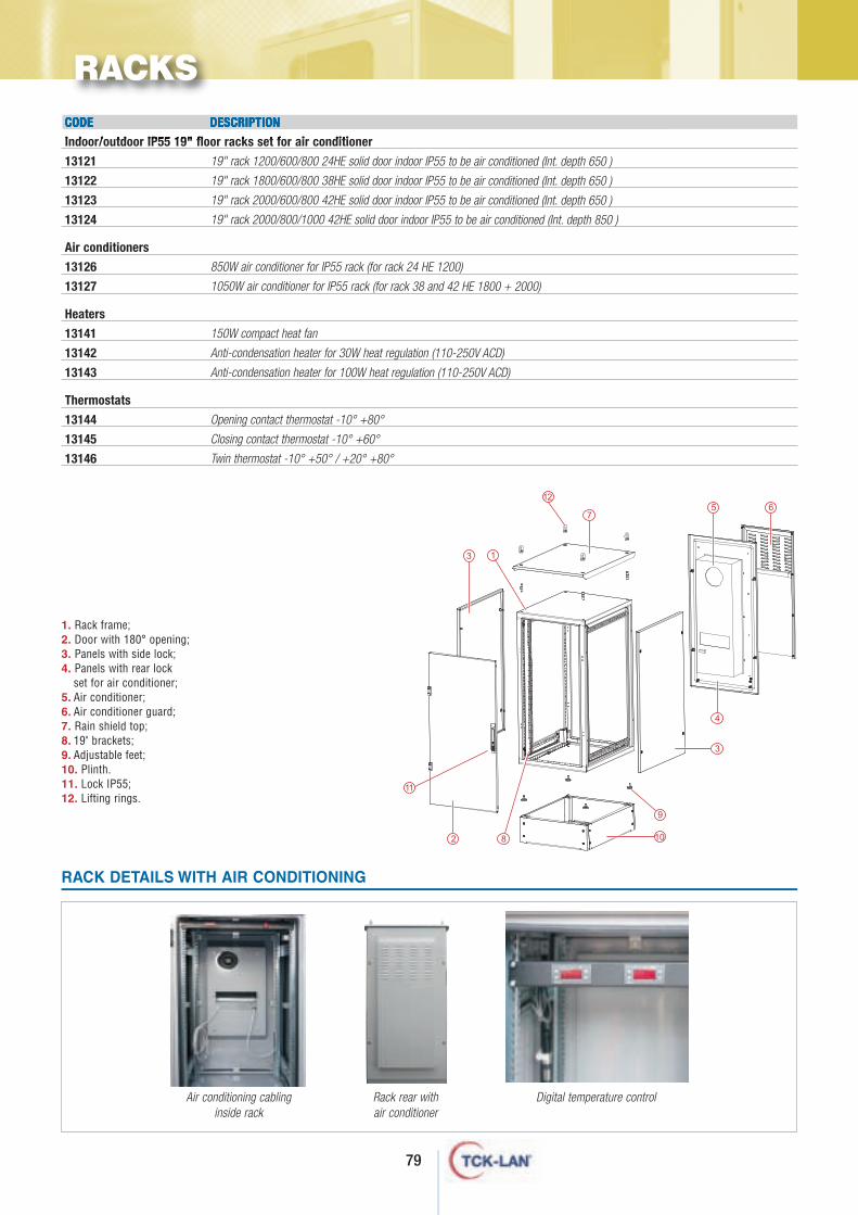
79
CODE DESCRIPTION
Indoor/outdoor IP55 19" floor racks set for air conditioner
13121
13122
13123
13124
Air conditioners
13126
13127
Heaters
13141
13142
13143
Thermostats
13144
13145
13146
19" rack 1200/600/800 24HE solid door indoor IP55 to be air conditioned (Int. depth 650 )
19" rack 1800/600/800 38HE solid door indoor IP55 to be air conditioned (Int. depth 650 )
19" rack 2000/600/800 42HE solid door indoor IP55 to be air conditioned (Int. depth 650 )
19" rack 2000/800/1000 42HE solid door indoor IP55 to be air conditioned (Int. depth 850 )
850W air conditioner for IP55 rack (for rack 24 HE 1200)
1050W air conditioner for IP55 rack (for rack 38 and 42 HE 1800 + 2000)
150W compact heat fan
Anti-condensation heater for 30W heat regulation (110-250V ACD)
Anti-condensation heater for 100W heat regulation (110-250V ACD)
Opening contact thermostat -10° +80°
Closing contact thermostat -10° +60°
Twin thermostat -10° +50° / +20° +80°
RACK DETAILS WITH AIR CONDITIONING
Air conditioning cablinginside rack
Rack rear withair conditioner
12
11
RACKS
1. Rack frame;2. Door with 180° opening;3. Panels with side lock;4. Panels with rear lock
set for air conditioner;5. Air conditioner;6. Air conditioner guard;7. Rain shield top;8. 19" brackets; 9. Adjustable feet; 10. Plinth. 11. Lock IP55; 12. Lifting rings.
Digital temperature control
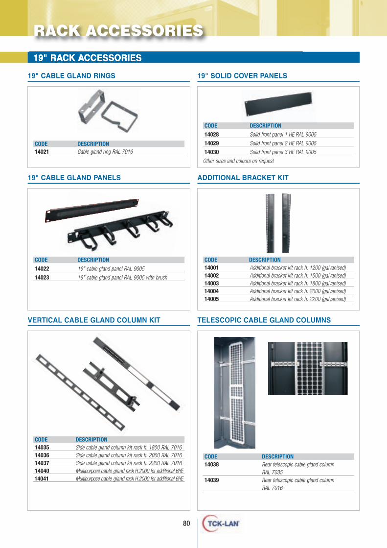
19" RACK ACCESSORIES
CODE DESCRIPTION14021 Cable gland ring RAL 7016
19" CABLE GLAND RINGS
CODE DESCRIPTION
14028 Solid front panel 1 HE RAL 9005
14029 Solid front panel 2 HE RAL 9005
14030 Solid front panel 3 HE RAL 9005
Other sizes and colours on request
19" SOLID COVER PANELS
CODE DESCRIPTION14001 Additional bracket kit rack h. 1200 (galvanised)14002 Additional bracket kit rack h. 1500 (galvanised)14003 Additional bracket kit rack h. 1800 (galvanised)14004 Additional bracket kit rack h. 2000 (galvanised)14005 Additional bracket kit rack h. 2200 (galvanised)
ADDITIONAL BRACKET KIT
CODE DESCRIPTION
14022 19" cable gland panel RAL 9005
14023 19" cable gland panel RAL 9005 with brush
19" CABLE GLAND PANELS
CODE DESCRIPTION14038 Rear telescopic cable gland column
RAL 703514039 Rear telescopic cable gland column
RAL 7016
TELESCOPIC CABLE GLAND COLUMNS
CODE DESCRIPTION14035 Side cable gland column kit rack h. 1800 RAL 701614036 Side cable gland column kit rack h. 2000 RAL 701614037 Side cable gland column kit rack h. 2200 RAL 701614040 Multipurpose cable gland rack H.2000 for additional 6HE14041 Multipurpose cable gland rack H.2000 for additional 6HE
VERTICAL CABLE GLAND COLUMN KIT
RACK ACCESSORIES
80
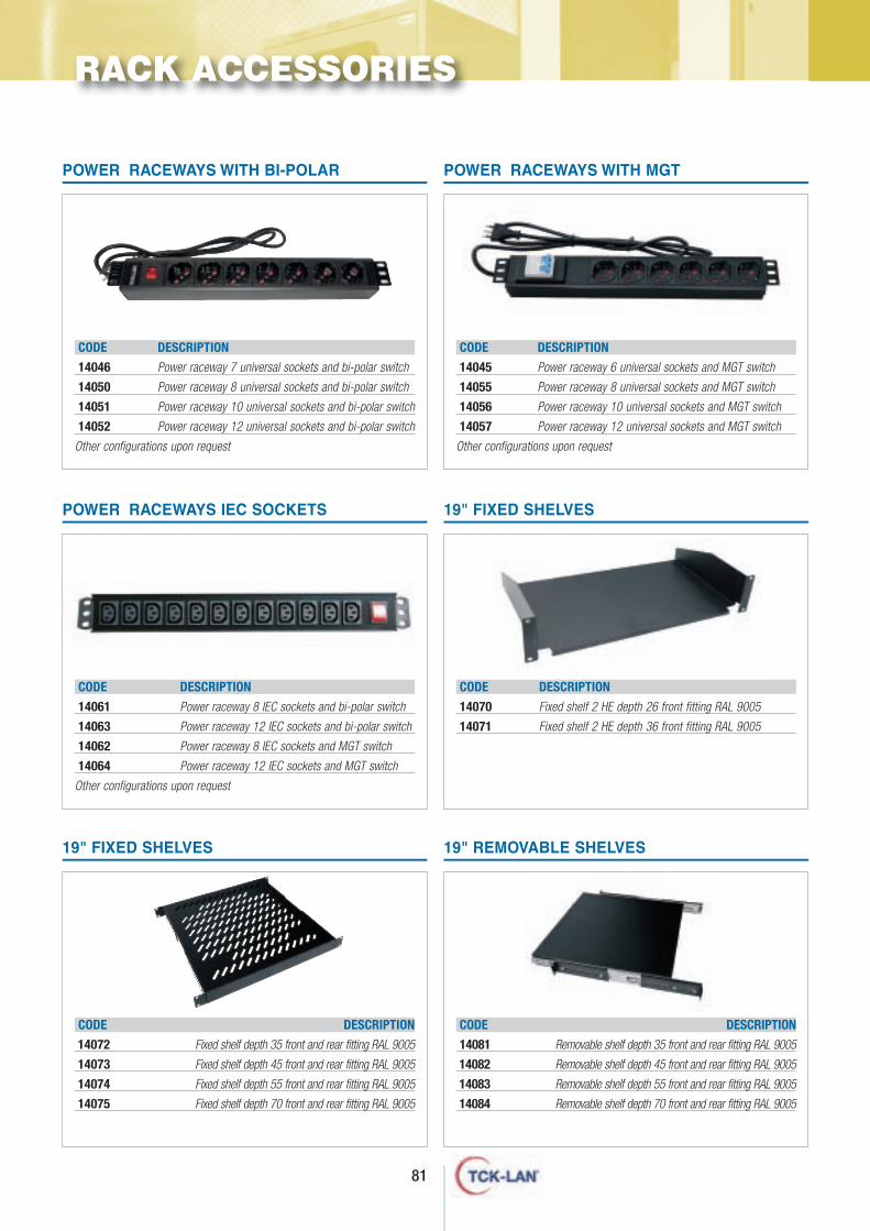
81
CODE DESCRIPTION
14046 Power raceway 7 universal sockets and bi-polar switch
14050 Power raceway 8 universal sockets and bi-polar switch
14051 Power raceway 10 universal sockets and bi-polar switch
14052 Power raceway 12 universal sockets and bi-polar switch
Other configurations upon request
POWER RACEWAYS WITH BI-POLAR
CODE DESCRIPTION
14045 Power raceway 6 universal sockets and MGT switch
14055 Power raceway 8 universal sockets and MGT switch
14056 Power raceway 10 universal sockets and MGT switch
14057 Power raceway 12 universal sockets and MGT switch
Other configurations upon request
POWER RACEWAYS WITH MGT
CODE DESCRIPTION
14061 Power raceway 8 IEC sockets and bi-polar switch
14063 Power raceway 12 IEC sockets and bi-polar switch
14062 Power raceway 8 IEC sockets and MGT switch
14064 Power raceway 12 IEC sockets and MGT switch
Other configurations upon request
POWER RACEWAYS IEC SOCKETS
CODE DESCRIPTION
14070 Fixed shelf 2 HE depth 26 front fitting RAL 9005
14071 Fixed shelf 2 HE depth 36 front fitting RAL 9005
19" FIXED SHELVES
CODE DESCRIPTION
14072 Fixed shelf depth 35 front and rear fitting RAL 9005
14073 Fixed shelf depth 45 front and rear fitting RAL 9005
14074 Fixed shelf depth 55 front and rear fitting RAL 9005
14075 Fixed shelf depth 70 front and rear fitting RAL 9005
19" FIXED SHELVES
CODE DESCRIPTION
14081 Removable shelf depth 35 front and rear fitting RAL 9005
14082 Removable shelf depth 45 front and rear fitting RAL 9005
14083 Removable shelf depth 55 front and rear fitting RAL 9005
14084 Removable shelf depth 70 front and rear fitting RAL 9005
19" REMOVABLE SHELVES
RACK ACCESSORIES
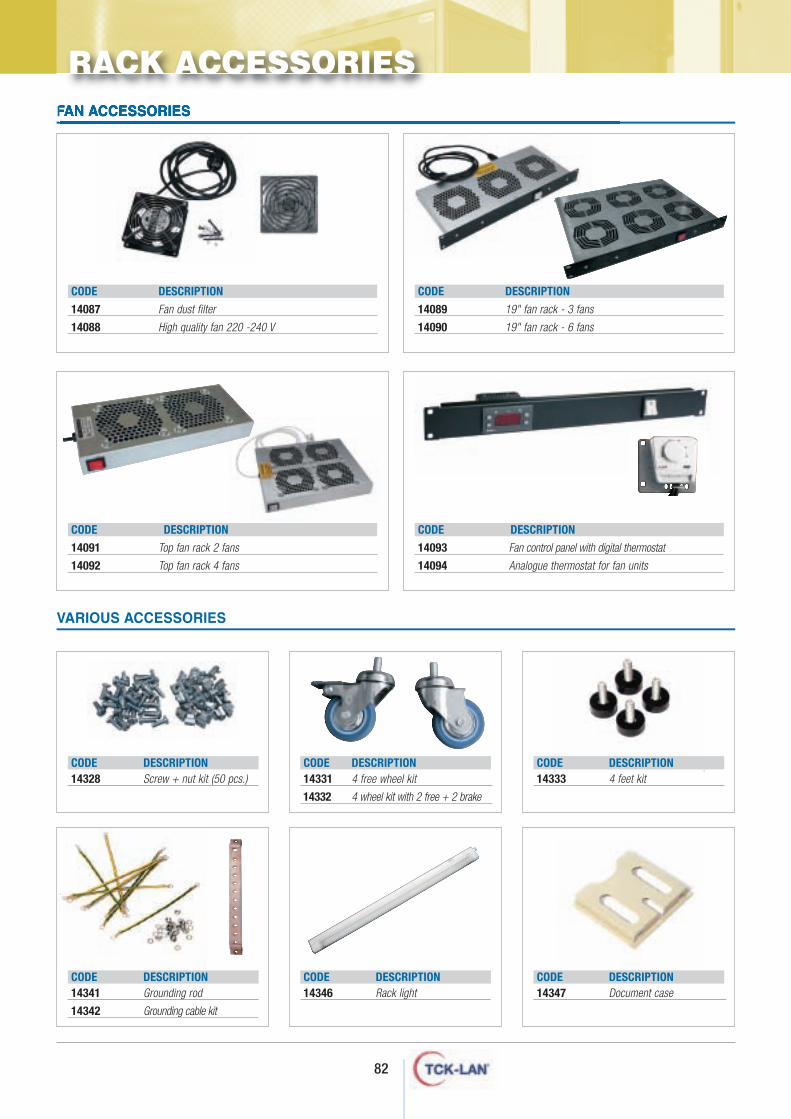
82
VARIOUS ACCESSORIES
CODE DESCRIPTION14328 Screw + nut kit (50 pcs.)
CODE DESCRIPTION14331 4 free wheel kit
14332 4 wheel kit with 2 free + 2 brake
CODE DESCRIPTION14333 4 feet kit
CODE DESCRIPTION14341 Grounding rod
14342 Grounding cable kit
CODE DESCRIPTION14346 Rack light
CODE DESCRIPTION14347 Document case
CODE DESCRIPTION
14087 Fan dust filter
14088 High quality fan 220 -240 V
CODE DESCRIPTION
14091 Top fan rack 2 fans
14092 Top fan rack 4 fans
CODE DESCRIPTION
14089 19" fan rack - 3 fans
14090 19" fan rack - 6 fans
CODE DESCRIPTION
14093 Fan control panel with digital thermostat
14094 Analogue thermostat for fan units
FAN ACCESSORIES
RACK ACCESSORIES
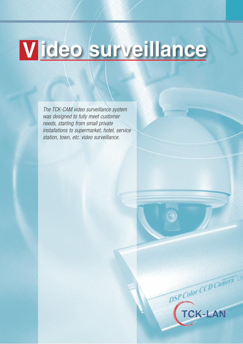
ideo surveillanceV
The TCK-CAM video surveillance systemwas designed to fully meet customerneeds, starting from small privateinstallations to supermarket, hotel, servicestation, town, etc. video surveillance.
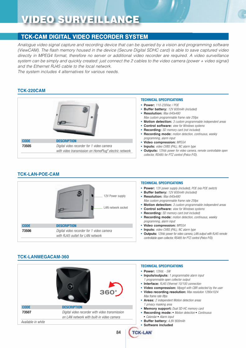
TCK-CAM DIGITAL VIDEO RECORDER SYSTEMAnalogue video signal capture and recording device that can be queried by a vision and programming software(ViewCAM). The flash memory housed in the device (Secure Digital SDHC card) is able to save captured videodirectly in MPEG4 format, therefore no server or additional video recorder are required. A video surveillancesystem can be simply and quickly created: just connect the 2 cables to the video camera (power + video signal)and the Ethernet RJ45 cable to the local network.The system includes 4 alternatives for various needs.
CODE DESCRIPTION73505 Digital video recorder for 1 video camera
with video transmission on HomePlug® electric network
TCK-220CAM
• Power: 110-230Vac / POE• Buffer battery: 12V 600mAh (included)• Resolution: Max 640x480
Max custom programmable frame rate 25fps • Motion detection: 3 custom programmable independent areas• Control software: view for Windows systems• Recording: SD memory card (not included)• Recording mode: motion detection, continuous, weekly
programming, alarm input• Video compression: MPEG4• Inputs: video CVBS (PAL), NC alarm type• Outputs: 12Vdc power for video camera, remote controllable open
collector, RS485 for PTZ control (Pelco P/D).
TECHNICAL SPECIFICATIONS
TCK-LAN-POE-CAM
• Power: 12V power supply (included), POE (via POE switch)• Buffer battery: 12V 600mAh (included)• Resolution: Max 640x480
Max custom programmable frame rate 25fps • Motion detection: 3 custom programmable independent areas• Control software: view for Windows systems• Recording: SD memory card (not included)• Recording mode: motion detection, continuous, weekly
programming, alarm input• Video compression: MPEG4• Inputs: video CVBS (PAL), NC alarm type• Outputs: 12Vdc power for video camera, LAN output with RJ45 remote
controllable open collector, RS485 for PTZ control (Pelco P/D).
TECHNICAL SPECIFICATIONS
CODE DESCRIPTION73506 Digital video recorder for 1 video camera
with RJ45 outlet for LAN network
VIDEO SURVEILLANCE
84
12V Power supply
LAN network socket
CODE DESCRIPTION73507 Digital video recorder with video transmission
on LAN network with built-in video camera
TCK-LANMEGACAM-360
• Power: 12Vdc - 5W• Inputs/outputs: 1 programmable alarm input
1 programmable open collector output• Interface: RJ45 Ethernet 10/100 connection• Video compression: Mpeg4 with CBR selected by the user• Video recording resolution: Max resolution 1280x1024
Max frame rate 8fps• Areas: 2 independent Motion detection areas
1 privacy masking area• Memory support: Dual SD-HC memory card• Recording mode: • Motion detection • Continuous
• Calendar • Alarm input• Buffer battery: 4,8V 800mAh• Software included
TECHNICAL SPECIFICATIONS
s
360°
Available in white
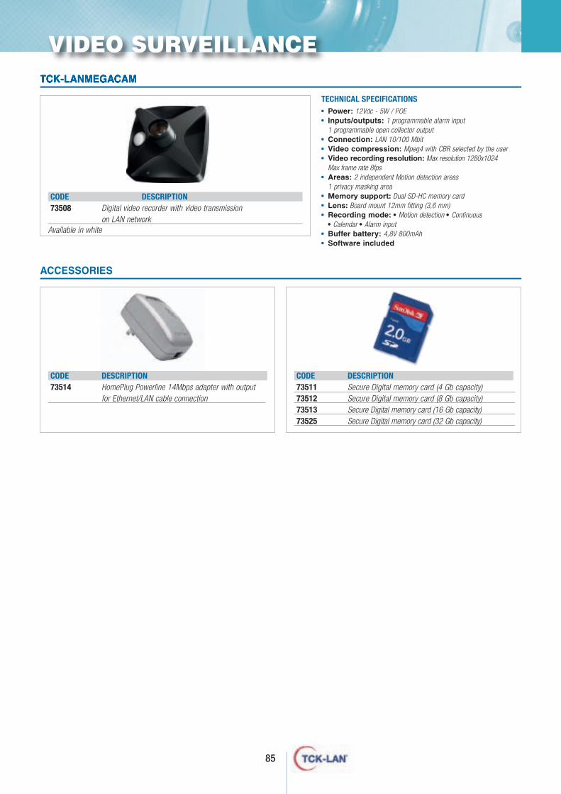
85
TCK-LANMEGACAM
TECHNICAL SPECIFICATIONS
CODE DESCRIPTION73508 Digital video recorder with video transmission
on LAN network
• Power: 12Vdc - 5W / POE• Inputs/outputs: 1 programmable alarm input
1 programmable open collector output• Connection: LAN 10/100 Mbit• Video compression: Mpeg4 with CBR selected by the user• Video recording resolution: Max resolution 1280x1024
Max frame rate 8fps• Areas: 2 independent Motion detection areas
1 privacy masking area• Memory support: Dual SD-HC memory card• Lens: Board mount 12mm fitting (3,6 mm)• Recording mode: • Motion detection • Continuous
• Calendar • Alarm input• Buffer battery: 4,8V 800mAh• Software included
ACCESSORIES
CODE DESCRIPTION73514 HomePlug Powerline 14Mbps adapter with output
for Ethernet/LAN cable connection
CODE DESCRIPTION73511 Secure Digital memory card (4 Gb capacity)73512 Secure Digital memory card (8 Gb capacity)73513 Secure Digital memory card (16 Gb capacity)73525 Secure Digital memory card (32 Gb capacity)
VIDEO SURVEILLANCE
Available in white
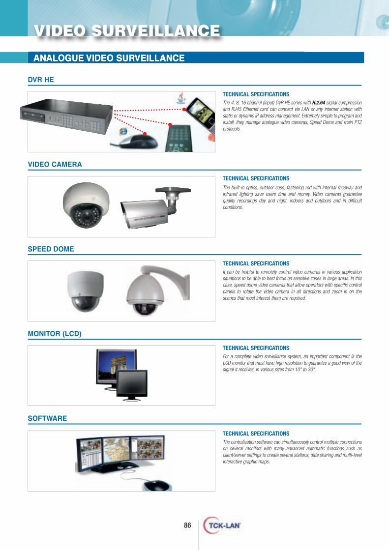
86
ANALOGUE VIDEO SURVEILLANCE
DVR HE
The 4, 8, 16 channel (input) DVR HE series with H.2.64 signal compressionand RJ45 Ethernet card can connect via LAN or any internet station withstatic or dynamic IP address management. Extremely simple to program andinstall, they manage analogue video cameras, Speed Dome and main PTZprotocols.
TECHNICAL SPECIFICATIONS
VIDEO CAMERA
The built-in optics, outdoor case, fastening rod with internal raceway andinfrared lighting save users time and money. Video cameras guaranteequality recordings day and night, indoors and outdoors and in difficultconditions.
TECHNICAL SPECIFICATIONS
SPEED DOME
It can be helpful to remotely control video cameras in various applicationsituations to be able to best focus on sensitive zones in large areas. In thiscase, speed dome video cameras that allow operators with specific controlpanels to rotate the video camera in all directions and zoom in on thescenes that most interest them are required.
TECHNICAL SPECIFICATIONS
MONITOR (LCD)
SOFTWARE
For a complete video surveillance system, an important component is theLCD monitor that must have high resolution to guarantee a good view of thesignal it receives. In various sizes from 10" to 30".
TECHNICAL SPECIFICATIONS
The centralisation software can simultaneously control multiple connectionson several monitors with many advanced automatic functions such asclient/server settings to create several stations, data sharing and multi-levelinteractive graphic maps.
TECHNICAL SPECIFICATIONS
VIDEO SURVEILLANCE
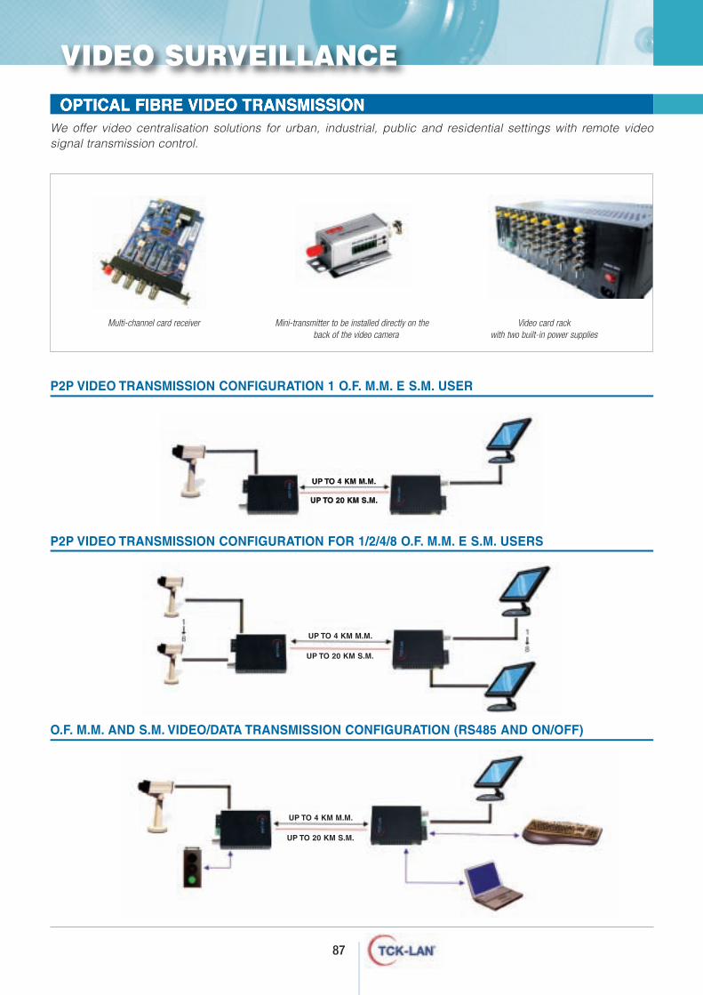
87
OPTICAL FIBRE VIDEO TRANSMISSION We offer video centralisation solutions for urban, industrial, public and residential settings with remote videosignal transmission control.
Multi-channel card receiver Mini-transmitter to be installed directly on theback of the video camera
Video card rackwith two built-in power supplies
P2P VIDEO TRANSMISSION CONFIGURATION 1 O.F. M.M. E S.M. USER
P2P VIDEO TRANSMISSION CONFIGURATION FOR 1/2/4/8 O.F. M.M. E S.M. USERS
O.F. M.M. AND S.M. VIDEO/DATA TRANSMISSION CONFIGURATION (RS485 AND ON/OFF)
VIDEO SURVEILLANCE
UP TO 20 KM S.M.
UP TO 4 KM M.M.
UP TO 20 KM S.M.
UP TO 4 KM M.M.
UP TO 20 KM S.M.
UP TO 4 KM M.M.
UP TO 20 KM S.M.
UP TO 4 KM M.M.
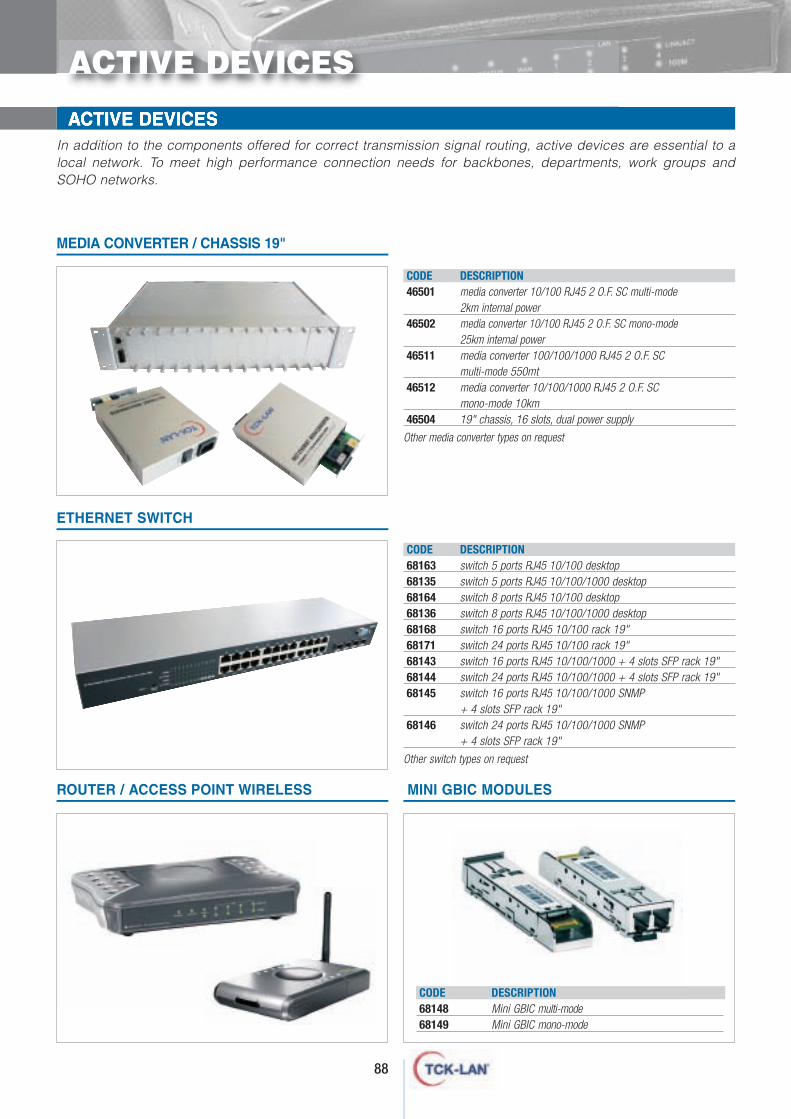
ACTIVE DEVICESIn addition to the components offered for correct transmission signal routing, active devices are essential to alocal network. To meet high performance connection needs for backbones, departments, work groups andSOHO networks.
ROUTER / ACCESS POINT WIRELESS
MEDIA CONVERTER / CHASSIS 19"
ETHERNET SWITCH
MINI GBIC MODULES
ACTIVE DEVICES
88
CODE DESCRIPTION46501 media converter 10/100 RJ45 2 O.F. SC multi-mode
2km internal power46502 media converter 10/100 RJ45 2 O.F. SC mono-mode
25km internal power46511 media converter 100/100/1000 RJ45 2 O.F. SC
multi-mode 550mt46512 media converter 10/100/1000 RJ45 2 O.F. SC
mono-mode 10km46504 19" chassis, 16 slots, dual power supply
Other media converter types on request
CODE DESCRIPTION68163 switch 5 ports RJ45 10/100 desktop68135 switch 5 ports RJ45 10/100/1000 desktop68164 switch 8 ports RJ45 10/100 desktop68136 switch 8 ports RJ45 10/100/1000 desktop68168 switch 16 ports RJ45 10/100 rack 19"68171 switch 24 ports RJ45 10/100 rack 19"68143 switch 16 ports RJ45 10/100/1000 + 4 slots SFP rack 19"68144 switch 24 ports RJ45 10/100/1000 + 4 slots SFP rack 19"68145 switch 16 ports RJ45 10/100/1000 SNMP
+ 4 slots SFP rack 19"68146 switch 24 ports RJ45 10/100/1000 SNMP
+ 4 slots SFP rack 19"
Other switch types on request
CODE DESCRIPTION68148 Mini GBIC multi-mode68149 Mini GBIC mono-mode
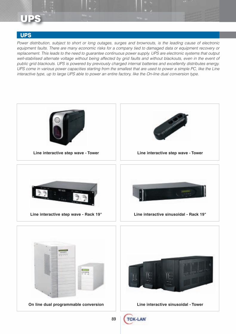
89
WALL-MOUNTED RACKS Power distribution, subject to short or long outages, surges and brownouts, is the leading cause of electronicequipment faults. There are many economic risks for a company tied to damaged data or equipment recovery orreplacement. This leads to the need to guarantee continuous power supply. UPS are electronic systems that outputwell-stabilised alternate voltage without being affected by grid faults and without blackouts, even in the event ofpublic grid blackouts. UPS is powered by previously charged internal batteries and excellently distributes energy.UPS come in various power capacities starting from the smallest that are used to power a simple PC, like the Lineinteractive type, up to large UPS able to power an entire factory, like the On-line dual conversion type.
WALL-MOUNTED RACKS UPS
UPS
Line interactive step wave - Tower Line interactive step wave - Tower
Line interactive step wave - Rack 19" Line interactive sinusoidal - Rack 19"
On line dual programmable conversion Line interactive sinusoidal - Tower
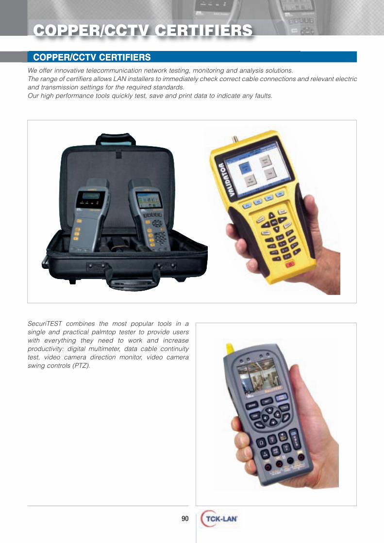
90
COPPER/CCTV CERTIFIERSWe offer innovative telecommunication network testing, monitoring and analysis solutions.The range of certifiers allows LAN installers to immediately check correct cable connections and relevant electricand transmission settings for the required standards.Our high performance tools quickly test, save and print data to indicate any faults.
SecuriTEST combines the most popular tools in asingle and practical palmtop tester to provide userswith everything they need to work and increaseproductivity: digital multimeter, data cable continuitytest, video camera direction monitor, video cameraswing controls (PTZ).
COPPER/CCTV CERTIFIERS

91
OTDROTDR is a reader used to analyse and find optical fibre faults. It can beused to test cables before installation. Analysis lets the user assess theoptical fibre length and attenuation, including any events such asjunctions, pairing, connections, point defects and introducedattenuation. A fibre break can be identified and its distance from theanalysis point estimated. Multi-mode, mono-mode and dual windowtest tools are available (various models).
SPLICERSThis tool automatically splices and aligns cores with relevant tests. Anextremely compact and lightweight tool, it includes a fibre splicingsystem in a wind protection device to optimise splicing.Quickly splicing, it comes with a durable battery to splice cables evenwithout electricity (various models available).
POWER METERThe most critical test is end to end attenuation. Our optical fibrecertifiers are ideal for LAN installers who need to measure multi-mode and mono-mode attenuation. Certification ensures terminationquality according to reference standards (various models available).
FIBER SCOPEInspecting the optical fibre termination under a microscope can beeasy if performed in a laboratory. FiberScope lets users easily inspectconnectors in the field. It can also save connector data for subsequentassessments. FiberScope is the only tool with such high performance.It does not require PC connection on the field or special software. Itacquires the image via a built-in camera and displays it on the 9" LCDmonitor, saving data on an SD memory card.
O.F. TOOLS
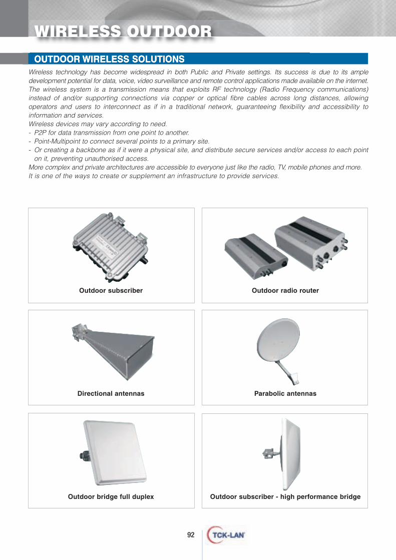
92
OUTDOOR WIRELESS SOLUTIONS
WIRELESS OUTDOOR
Wireless technology has become widespread in both Public and Private settings. Its success is due to its ampledevelopment potential for data, voice, video surveillance and remote control applications made available on the internet.The wireless system is a transmission means that exploits RF technology (Radio Frequency communications)instead of and/or supporting connections via copper or optical fibre cables across long distances, allowingoperators and users to interconnect as if in a traditional network, guaranteeing flexibility and accessibility toinformation and services.Wireless devices may vary according to need.- P2P for data transmission from one point to another.- Point-Multipoint to connect several points to a primary site.- Or creating a backbone as if it were a physical site, and distribute secure services and/or access to each point
on it, preventing unauthorised access.More complex and private architectures are accessible to everyone just like the radio, TV, mobile phones and more.It is one of the ways to create or supplement an infrastructure to provide services.
Outdoor subscriber Outdoor radio router
Directional antennas Parabolic antennas
Outdoor bridge full duplex Outdoor subscriber - high performance bridge