Embed Size (px)
Citation preview

l ::: J 800-253-8324
iBeamUSA.com MetraDealer.com
� TECH SUPPORT
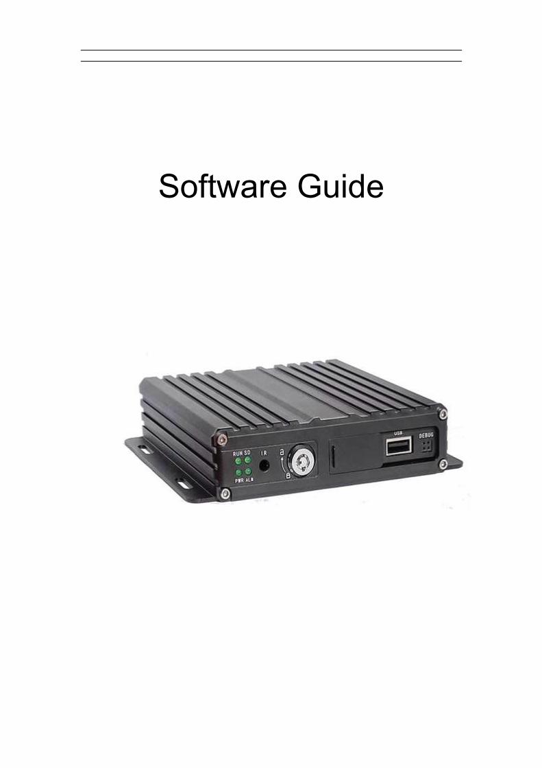
TE-CDVR-4 & TE-CDVR-GUser Manual
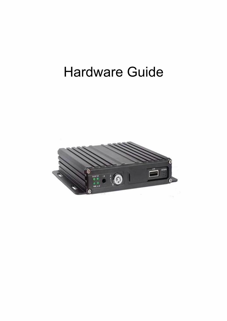
Hardware Guide
I
Catalogue
Chapter 1 Accessories and Interface ...................................................................................... 1
1.DVR and accessories ..................................................................................................... 12.System connection ......................................................................................................... 2
3.Panel introduction........................................................................................................... 3
4.Interfaces Definition ....................................................................................................... 3
4.1 Power interface ............................................................................................................... 3
4.2 I/O Interface definition ................................................................................................... 4
4.3 Aviation interface definition ......................................................................................... 4
Chapter 2 Installation and Application ................................................................................... 4
1.SD card installation ........................................................................................................ 4
2.Antennas Connection .................................................................................................... 5
3.Power Connection........................................................................................................... 6
4. Camera Connection .......................................................................................................... 6
5.Monitor connection ......................................................................................................... 7
6.I/O wires connection ....................................................................................................... 8
6. Alarm input connection .................................................................................................. 86.1 Reverse assistant .......................................................................................................... 96.2 Serial ports connection ............................................................................................... 11
1
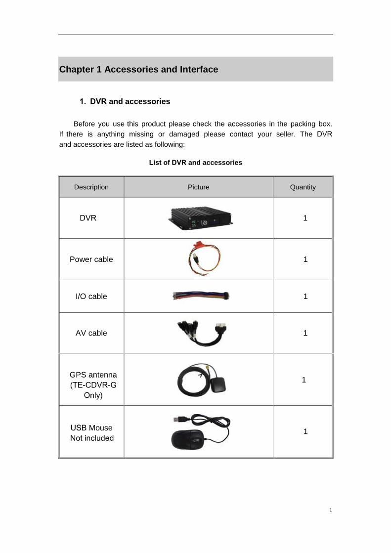
Chapter 1 Accessories and Interface
1. DVR and accessories
Before you use this product please check the accessories in the packing box.
If there is anything missing or damaged please contact your seller. The DVRand accessories are listed as following:
List of DVR and accessories
Description Picture Quantity
DVR 1
Power cable 1
I/O cable 1
AV cable 1
GPS antenna
(TE-CDVR-G Only)
1
1 USB Mouse
Not included
2
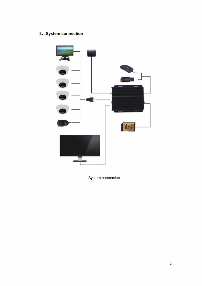
2.System connection
System connection
3
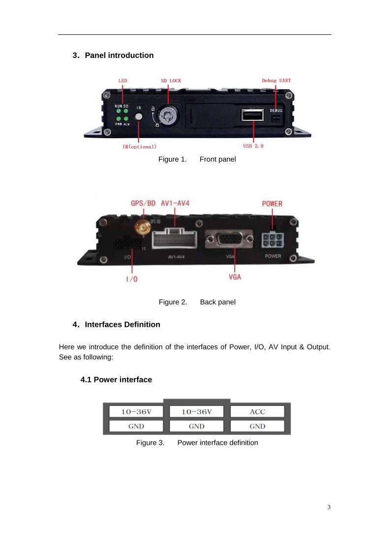
3.Panel introduction
Figure 1. Front panel
Figure 2. Back panel
4.Interfaces Definition
Here we introduce the definition of the interfaces of Power, I/O, AV Input & Output.
See as following:
4.1 Power interface
Figure 3. Power interface definition
4
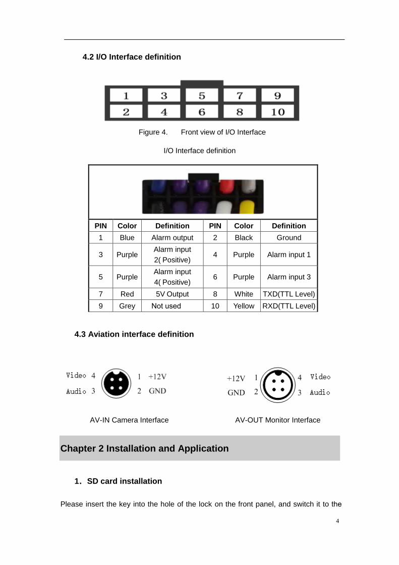
4.2 I/O Interface definition
Figure 4. Front view of I/O Interface
I/O Interface definition
4.3 Aviation interface definition
AV-IN Camera Interface AV-OUT Monitor Interface
Chapter 2 Installation and Application
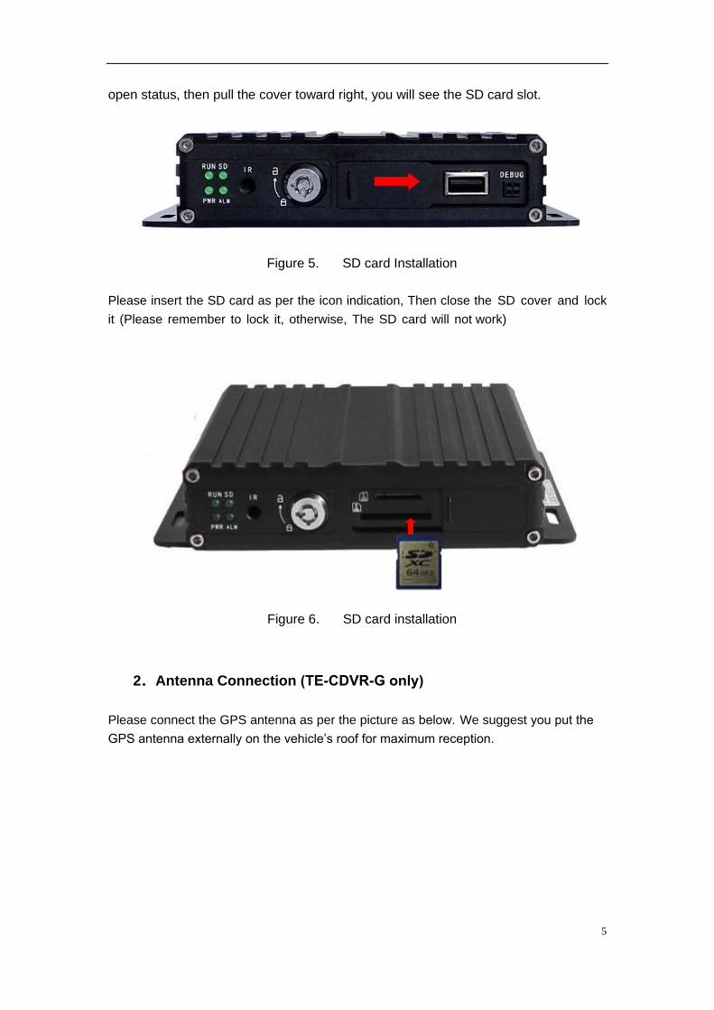
1.SD card installation
Please insert the key into the hole of the lock on the front panel, and switch it to the
PIN Color Definition PIN Color Definition
1 Blue Alarm output 2 Black Ground
3 Purple Alarm input
2( Positive) 4 Purple Alarm input 1
5 Purple Alarm input
4( Positive) 6 Purple Alarm input 3
7 Red 5V Output 8 White TXD(TTL Level)
9 Grey Not used 10 Yellow RXD(TTL Level)
5
open status, then pull the cover toward right, you will see the SD card slot.
Figure 5. SD card Installation
Please insert the SD card as per the icon indication, Then close the SD cover and lock
it (Please remember to lock it, otherwise, The SD card will not work)
Figure 6. SD card installation
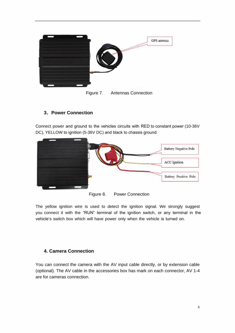
2.Antenna Connection (TE-CDVR-G only)
Please connect the GPS antenna as per the picture as below. We suggest you put the
GPS antenna externally on the vehicle’s roof for maximum reception.
6
Figure 7. Antennas Connection
3.Power Connection
Connect power and ground to the vehicles circuits with RED to constant power (10-36V
DC), YELLOW to ignition (5-36V DC) and black to chassis ground.
Figure 8. Power Connection
The yellow ignition wire is used to detect the ignition signal. We strongly suggest
you connect it with the “RUN” terminal of the ignition switch, or any terminal in the
vehicle’s switch box which will have power only when the vehicle is turned on.
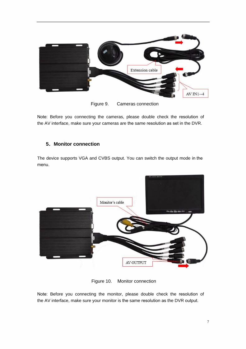
4. Camera Connection
You can connect the camera with the AV input cable directly, or by extension cable
(optional). The AV cable in the accessories box has mark on each connector, AV 1-4
are for cameras connection.
g
g
p
s
7
Figure 9. Cameras connection
Note: Before you connecting the cameras, please double check the resolution of
the AV interface, make sure your cameras are the same resolution as set in the DVR.
5.Monitor connection
The device supports VGA and CVBS output. You can switch the output mode in the menu.
Figure 10. Monitor connection
Note: Before you connecting the monitor, please double check the resolution of
the AV interface, make sure your monitor is the same resolution as the DVR output.
8
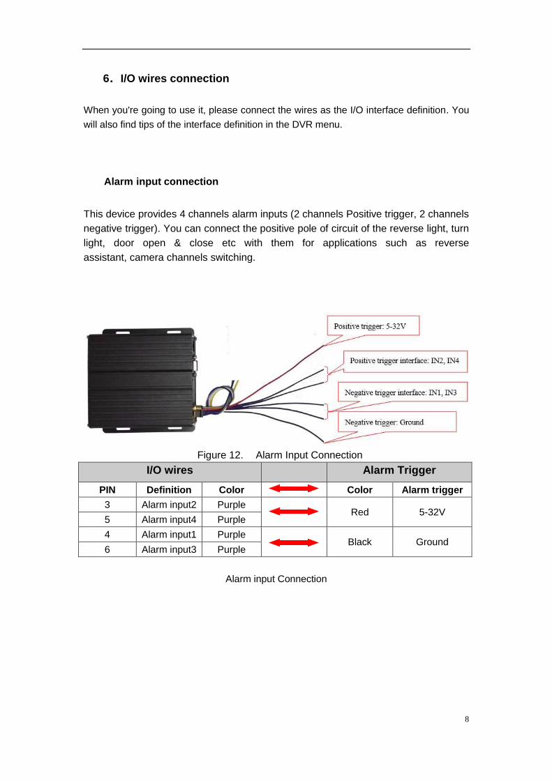
6.I/O wires connection
When you're going to use it, please connect the wires as the I/O interface definition. You
will also find tips of the interface definition in the DVR menu.
Alarm input connection
This device provides 4 channels alarm inputs (2 channels Positive trigger, 2 channels
negative trigger). You can connect the positive pole of circuit of the reverse light, turn
light, door open & close etc with them for applications such as reverse
assistant, camera channels switching.
Figure 12. Alarm Input Connection
I/O wires Alarm Trigger
PIN Definition Color Color Alarm trigger
3 Alarm input2 Purple Red 5-32V
5 Alarm input4 Purple
4 Alarm input1 Purple Black Ground
6 Alarm input3 Purple
Alarm input Connection
9
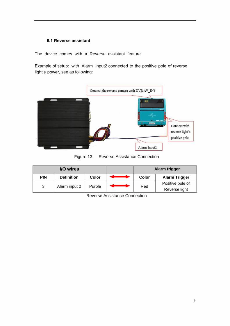
6.1 Reverse assistant
The device comes with a Reverse assistant feature.
Example of setup: with Alarm Input2 connected to the positive pole of reverse
light’s power, see as following:
Figure 13. Reverse Assistance Connection
I/O wires Alarm trigger
PIN Definition Color Color Alarm Trigger
3 Alarm input 2 Purple Red Positive pole of
Reverse light
Reverse Assistance Connection
10
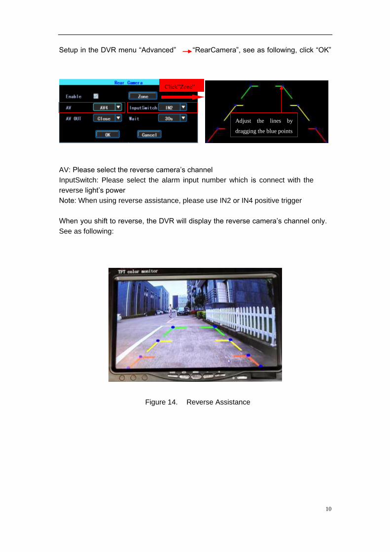
“RearCamera”, see as following, click “OK” Setup in the DVR menu “Advanced”
AV: Please select the reverse camera’s channel
InputSwitch: Please select the alarm input number which is connect with the
reverse light’s power
Note: When using reverse assistance, please use IN2 or IN4 positive trigger
When you shift to reverse, the DVR will display the reverse camera’s channel only.
See as following:
Figure 14. Reverse Assistance
Click”Zone”
Adjust the lines by
dragging the blue points
11
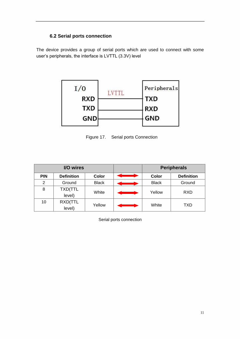
6.2 Serial ports connection
The device provides a group of serial ports which are used to connect with some
user’s peripherals, the interface is LVTTL (3.3V) level
Figure 17. Serial ports Connection
I/O wires Peripherals
PIN Definition Color Color Definition
2 Ground Black Black Ground
8 TXD(TTL
level) White Yellow RXD
10 RXD(TTL
level) Yellow White TXD
Serial ports connection
Software Guide
~ I ~
Catalogue
Chapter 1 Overview .................................................................................................................. 1
Chapter 2 Quick setup ............................................................................................................. 1
1.Device Installation ........................................................................................................... 1
2. User Login .......................................................................................................................... 1
3.Set up the System time .................................................................................................. 2
4.Set up cameras ................................................................................................................ 2
5.Wizard ................................................................................................................................ 3
Chapter 3 System Menu .......................................................................................................... 4
1.1 Video Playback ......................................................................................................... 4
1.2 Video Backup ............................................................................................................ 4
2.Basic Setting .................................................................................................................... 5
2.1 Date Time setting ..................................................................................................... 5
2.2 Vehicle Information .................................................................................................. 6
2.3 Preview setting ......................................................................................................... 6
2.3 Video Output ............................................................................................................. 7
2.4 On/Off setting ............................................................................................................ 7
2.5 System Information ................................................................................................ .7
3.Network setup ................................................................................................................. 9
4.Recording Setup ............................................................................................................. 94.1 Recording Mode setting ........................................................................................ 94.2 Main Stream ............................................................................................................. 104.3 Sub Stream .............................................................................................................. 104.4 Recording storage ................................................................................................. 114.5 Recording OSD (On Screen Display) ................................................................ 114.6 Image setting........................................................................................................... 124.7 Mirror setting........................................................................................................... 12
5.Advanced setting .......................................................................................................... 125.1 User Management .................................................................................................. 135.2 Driving Habits monitoring ................................................................................... 135.3 UART setting ........................................................................................................... 135.3.1 UART-TTS ............................................................................................................. 14
5.3.2 UART-Serial Net (Pass Through) .................................................................... 145.4 Reverse Camera ..................................................................................................... 145.5 NetTextShow ........................................................................................................... 15
2.6 System Setup . ........................................................................................................... 8
2.7 System Information ................................................................................................ .8
~ II ~
6.Device Maintenance ..................................................................................................... 166.1 Log Inquiry............................................................................................................... 166.2 Disk Management .................................................................................................. 176.3 Related with the Parameter ................................................................................. 176.4 System upgrading ................................................................................................. 17
7.Alarm setting .................................................................................................................. 187.1 Input Alarm .............................................................................................................. 187.2 AlarmOut setting .................................................................................................... 197.3 Video Loss ............................................................................................................... 207.4 Fatigue Driving Alarm ........................................................................................... 207.5 OverSpeedAlarm .................................................................................................... 217.6 DiskError .................................................................................................................. 21
Chapter 4 Installation Warnings .......................................................................................... 22
~ 1 ~
Chapter 1 Overview
TE-CDVR is a DVR designed for Analog HD vehicle monitoring. With built-in high
performance image processor and advanced H.264 video compression technology, it
provides AHD video recording, storage and playback solution. It comes with smart
power management system which can recognize the power type automatically. When
detected the battery’s voltage is lower than the given value, the device will shutdown automatically and keep ultra-low standby consumption.
Chapter 2 Quick setup
1.Device Installation
Please refer to Hardware Guide for installation and cables connection.
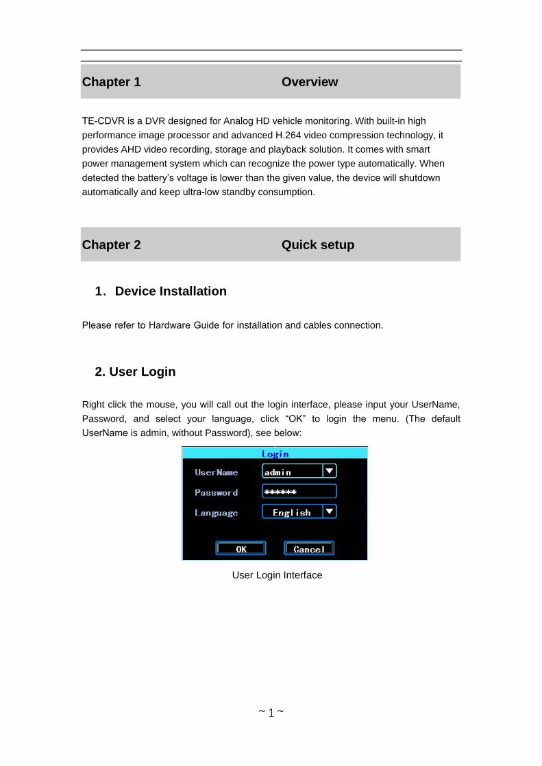
2. User Login
Right click the mouse, you will call out the login interface, please input your UserName,
Password, and select your language, click “OK” to login the menu. (The default
UserName is admin, without Password), see below:
User Login Interface
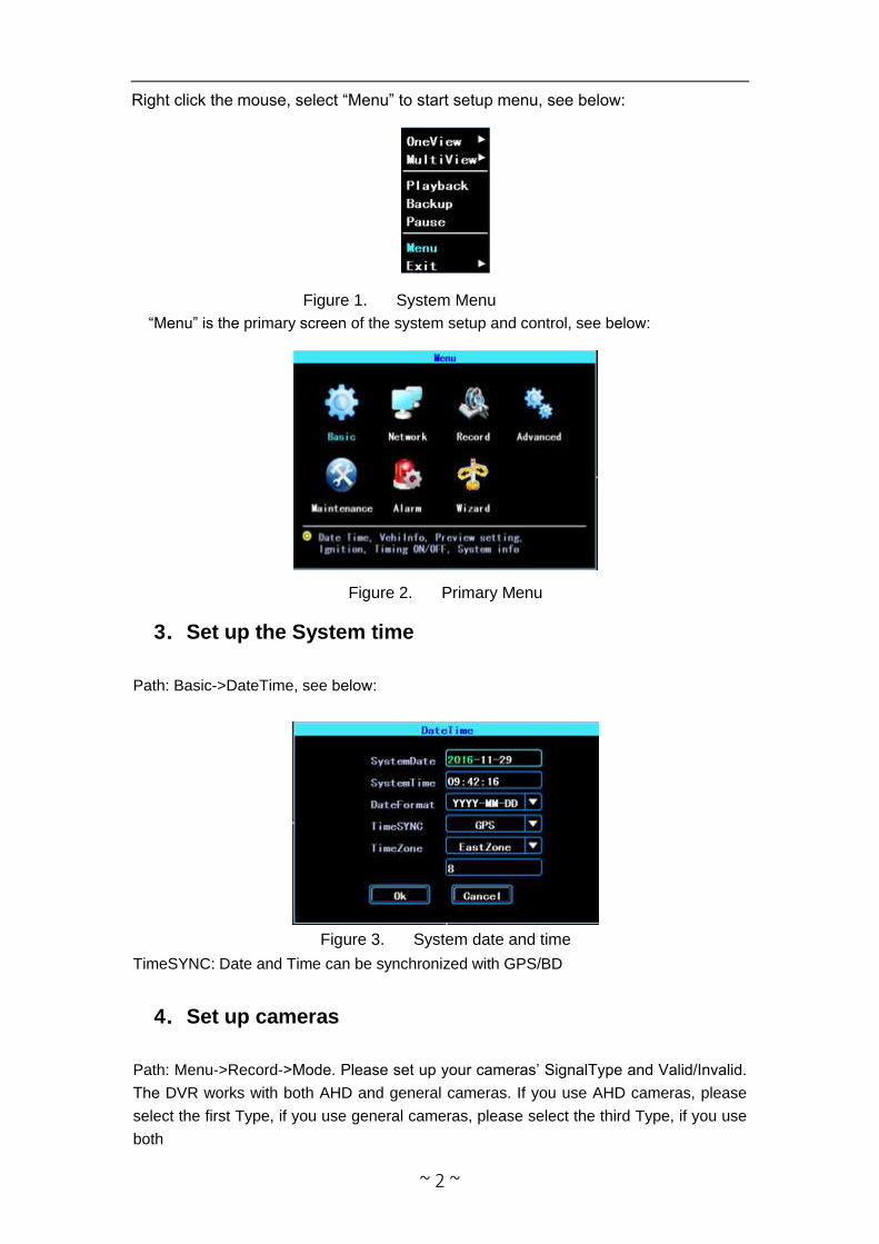
Figure 1. System Menu
“Menu” is the primary screen of the system setup and control, see below:
Figure 2. Primary Menu
3.Set up the System time
Path: Basic->DateTime, see below:
Figure 3. System date and time
TimeSYNC: Date and Time can be synchronized with GPS/BD
4.Set up cameras
Path: Menu->Record->Mode. Please set up your cameras’ SignalType and Valid/Invalid.
The DVR works with both AHD and general cameras. If you use AHD cameras, please
select the first Type, if you use general cameras, please select the third Type, if you use
both
~ 2 ~
Right click the mouse, select “Menu” to start setup menu, see below:
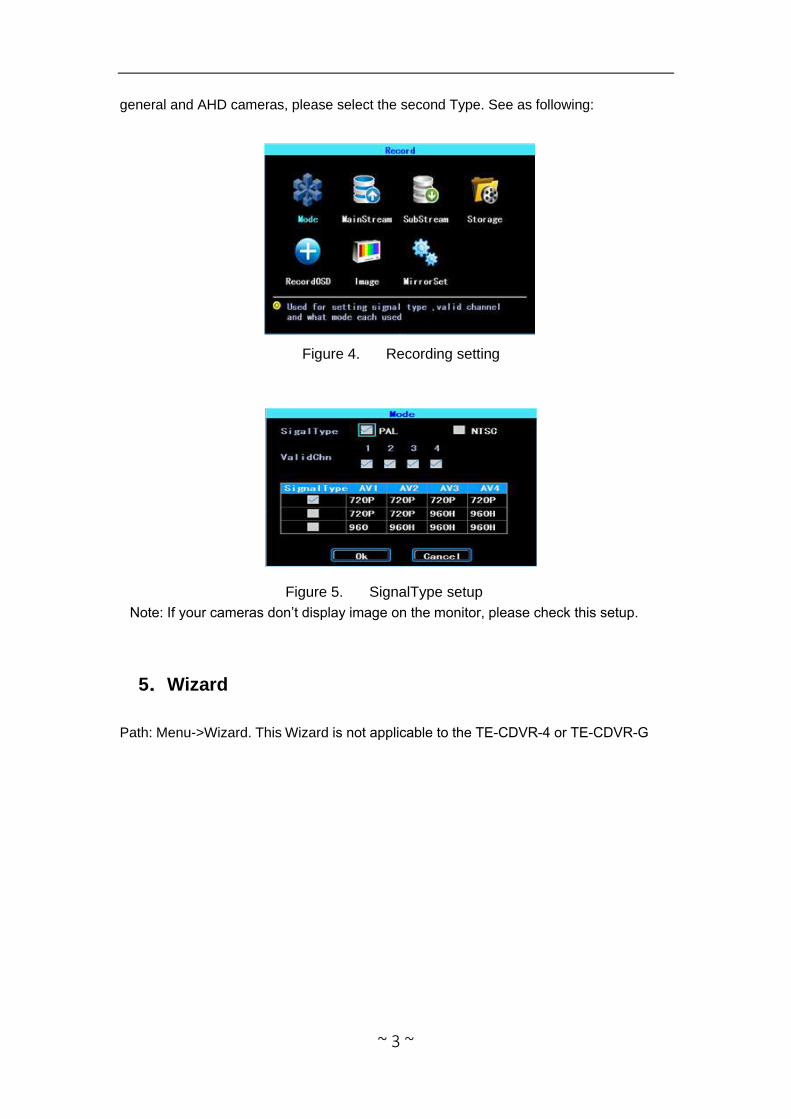
general and AHD cameras, please select the second Type. See as following:
Figure 4. Recording setting
Figure 5. SignalType setup
Note: If your cameras don’t display image on the monitor, please check this setup.
5.Wizard
Path: Menu->Wizard. This Wizard is not applicable to the TE-CDVR-4 or TE-CDVR-G
~ 3 ~
~ 4 ~
Chapter 3 System Menu
Figure 12. System menu
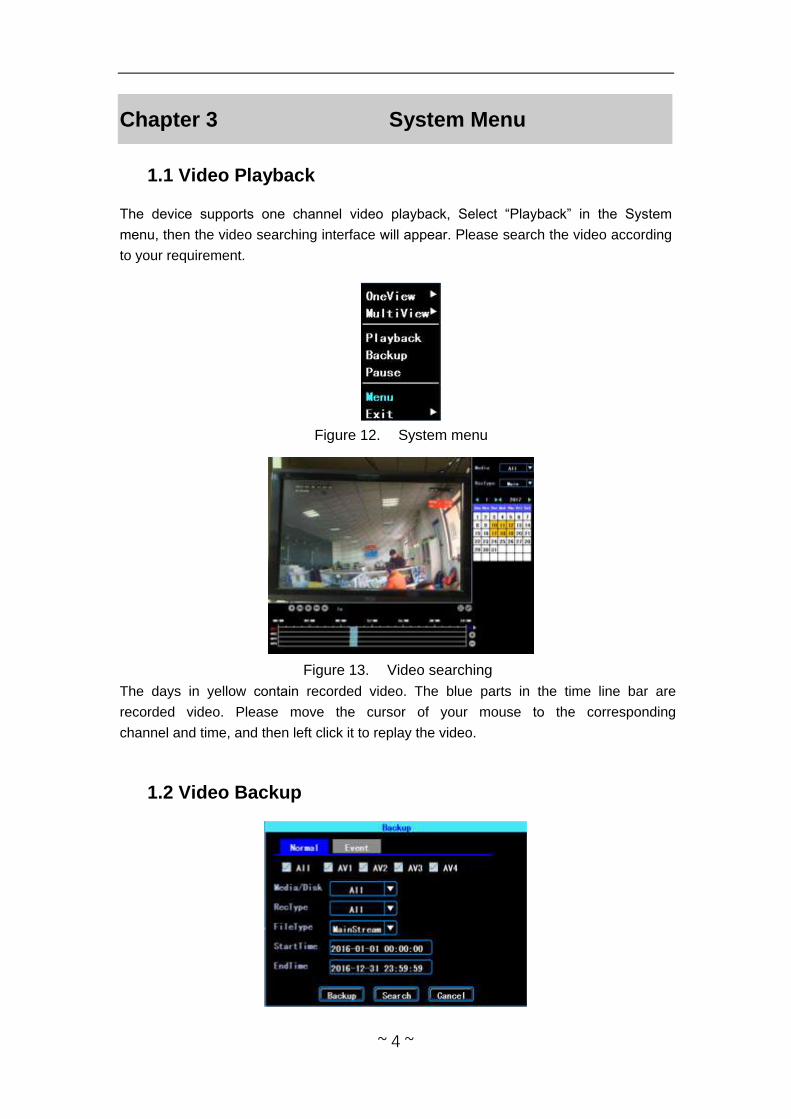
1.1 Video Playback
The device supports one channel video playback, Select “Playback” in the System
menu, then the video searching interface will appear. Please search the video according
to your requirement.
Figure 13. Video searching
The days in yellow contain recorded video. The blue parts in the time line bar are
recorded video. Please move the cursor of your mouse to the corresponding channel and time, and then left click it to replay the video.
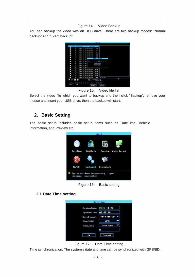
1.2 Video Backup
~ 5 ~
Figure 14. Video Backup
You can backup the video with an USB drive. There are two backup modes: “Normal
backup” and “Event backup”
Figure 15. Video file list
Select the video file which you want to backup and then click “Backup”, remove your
mouse and insert your USB drive, then the backup will start.
2.Basic Setting
The basic setup includes basic setup items such as DateTime, Vehicle
Information, and Preview etc.
Figure 16. Basic setting
2.1 Date Time setting
Figure 17. Date Time setting
Time synchronization: The system's date and time can be synchronized with GPS/BD.
~ 6 ~
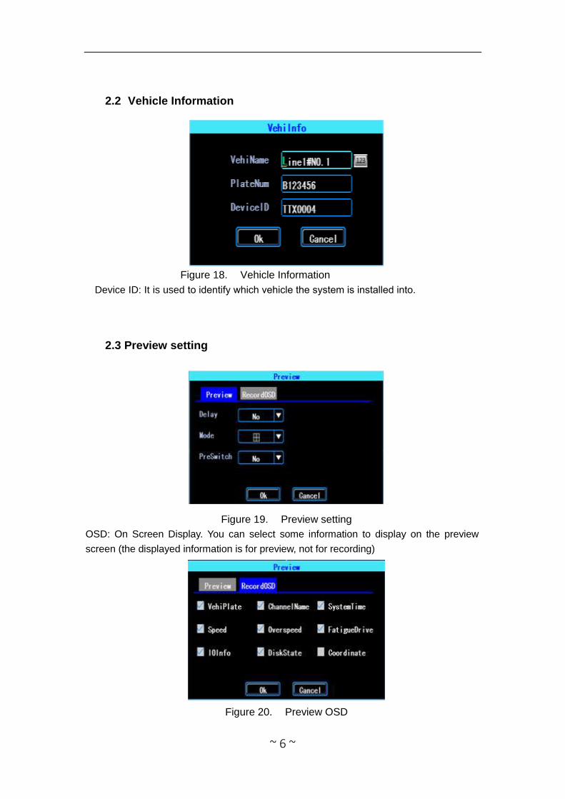
2.2 Vehicle Information
Figure 18. Vehicle Information
Device ID: It is used to identify which vehicle the system is installed into.
2.3 Preview setting
Figure 19. Preview setting
OSD: On Screen Display. You can select some information to display on the preview
screen (the displayed information is for preview, not for recording)
Figure 20. Preview OSD
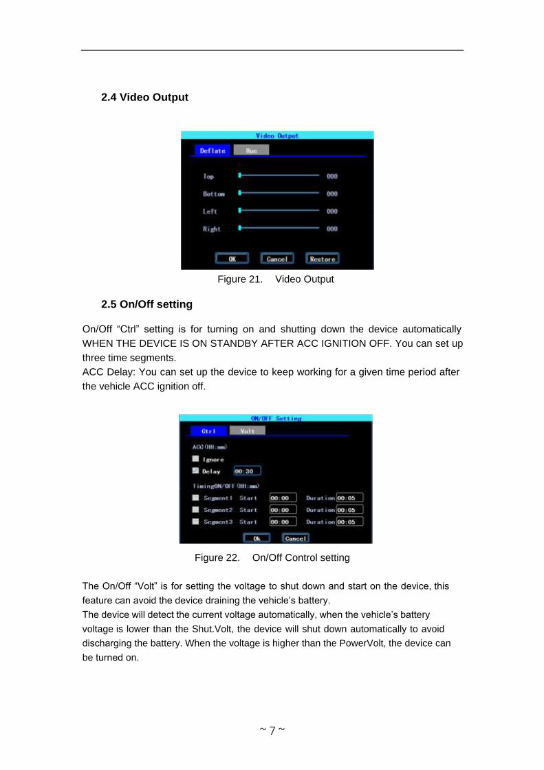
2.4 Video Output
Figure 21. Video Output
2.5 On/Off setting
On/Off “Ctrl” setting is for turning on and shutting down the device automatically
WHEN THE DEVICE IS ON STANDBY AFTER ACC IGNITION OFF. You can set up
three time segments.
ACC Delay: You can set up the device to keep working for a given time period after the vehicle ACC ignition off.
Figure 22. On/Off Control setting
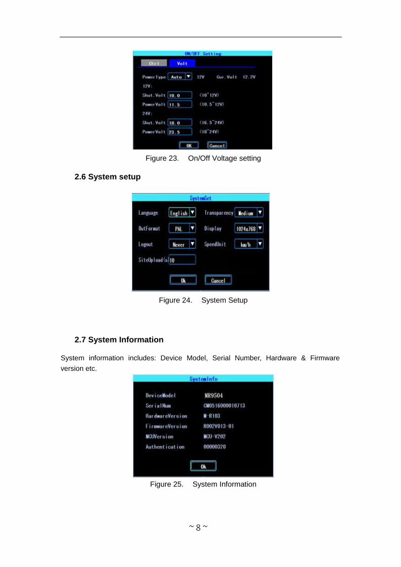
The On/Off “Volt” is for setting the voltage to shut down and start on the device, this
feature can avoid the device draining the vehicle’s battery.
The device will detect the current voltage automatically, when the vehicle’s battery
voltage is lower than the Shut.Volt, the device will shut down automatically to avoid
discharging the battery. When the voltage is higher than the PowerVolt, the device can
be turned on.
~ 7 ~
~ 8 ~
Figure 23. On/Off Voltage setting
2.6 System setup
Figure 24. System Setup
2.7 System Information
System information includes: Device Model, Serial Number, Hardware & Firmware
version etc.
Figure 25. System Information

3.Network setup (not used)
4.Recording Setup
Recording setup includes Mode, Main Stream, Sub Stream, Recording OSD, Image,
Mirror recording setting.
Figure 33. Recording setting
4.1 Recording Mode setting
Figure 34. Recording Mode setting
Please set up your camera Signal Type and Valid/Invalid. The DVR works with both
AHD and general cameras. If you use AHD cameras, please select the first Type, if
you use general cameras, please select the third Type, if you use both of general
and AHD cameras, please select the second Type.
~ 9 ~
~ 10 ~
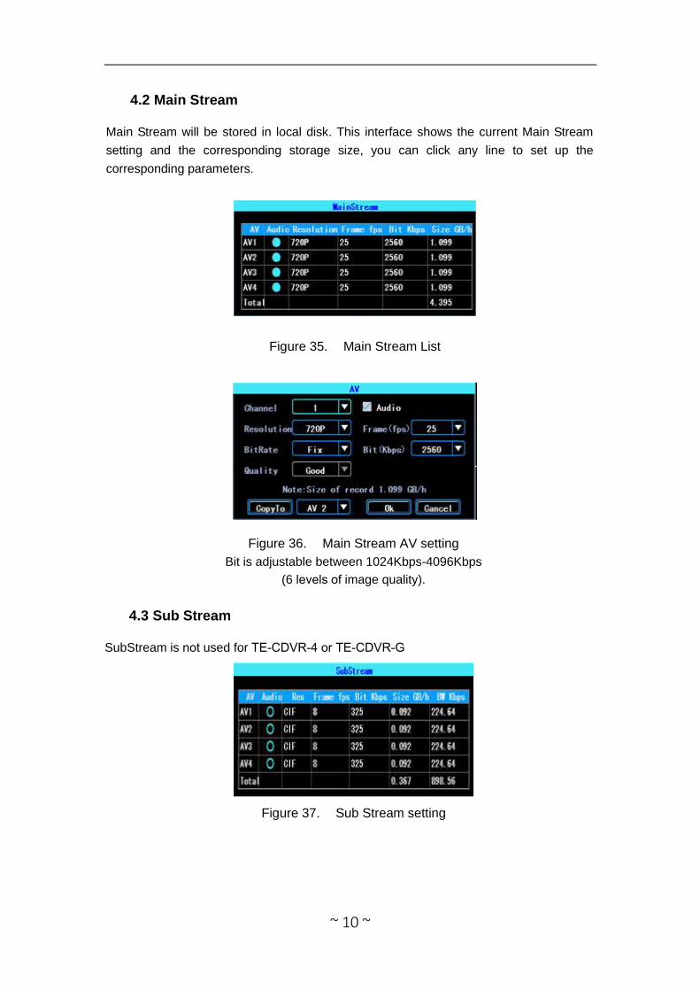
4.2 Main Stream
Main Stream will be stored in local disk. This interface shows the current Main Stream
setting and the corresponding storage size, you can click any line to set up the
corresponding parameters.
Figure 35. Main Stream List
Figure 36. Main Stream AV setting
Bit is adjustable between 1024Kbps-4096Kbps
(6 levels of image quality).
4.3 Sub Stream
SubStream is not used for TE-CDVR-4 or TE-CDVR-G
Figure 37. Sub Stream setting
4.4 Recording storage
4.5 Recording OSD (On Screen Display)
You can set up the information you want to be recorded in the
video. This information will be overlaid on the playback video.
~ 11 ~
Select to record to SD card and activate Over Write loop recording.
Figure 40. Recording OSD
4.6 Image setting
Image setup is used to adjust to camera’s image effect.
Figure 41. Image setup
4.7 Mirror setting
This feature can turn over the camera’s image horizontally or verticaly (for both
preview and recording)
Figure 42. Mirror setting
5.Advanced setting
~ 12 ~
This interface is used for UserManagement, Driving Habits monitoring, UART port
setting, Temperature Sensor, and Reverse Lines setting.
Figure 43. Advanced setting
5.1 User Management
You can add, modify, delete users, and modify the login username and privileges.
Figure 44. User Management
5.2 Driving Habits monitoring
(this feature is not available)
Figure 45. Driving Habits monitoring
5.3 UART setting
This device has 1 UART port (TTL). You can connect some peripheral devices such
as TTS (Text To Speech), Network Pass Through etc with the DVR via our UART
converter.
~ 13 ~
Figure 46. UART setting list
5.3.1 UART-TTS
Select UART to get into UART setting interface.
Select “TTS” in the drop-down box of “Function”. Config the parameters as per the
picture followed:
Figure 47. UART setting
5.3.2 UART-Serial Net (Pass Through)
Select UART to get into UART setting interface.
Select “SerialNet”(PassThrough)in the drop-down box of “Function”. Config the
parameters as per the picture followed:
Figure 48. UART setting
5.4 Reverse Camera
The DVR comes with Reverse camera function. Any channel can be used
for the reverse camera.~ 14 ~
~ 15 ~
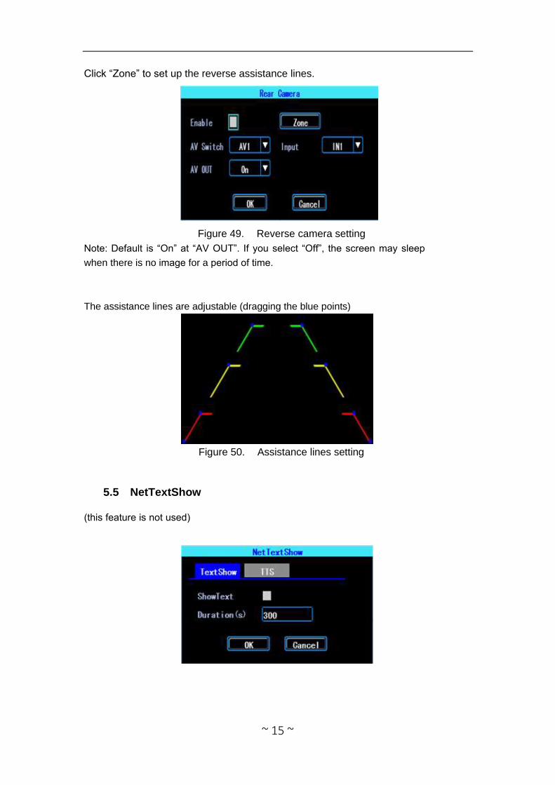
Click “Zone” to set up the reverse assistance lines.
Figure 49. Reverse camera setting
Note: Default is “On” at “AV OUT”. If you select “Off”, the screen may sleep
when there is no image for a period of time.
The assistance lines are adjustable (dragging the blue points)
Figure 50. Assistance lines setting
5.5 NetTextShow
(this feature is not used)
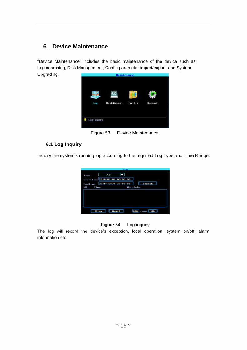
6.Device Maintenance
“Device Maintenance” includes the basic maintenance of the device such as
Log searching, Disk Management, Config parameter import/export, and System
Upgrading.
Figure 53. Device Maintenance.
6.1 Log Inquiry
Inquiry the system’s running log according to the required Log Type and Time Range.
~ 16 ~
Figure 54. Log inquiry
The log will record the device’s exception, local operation, system on/off, alarm
information etc.
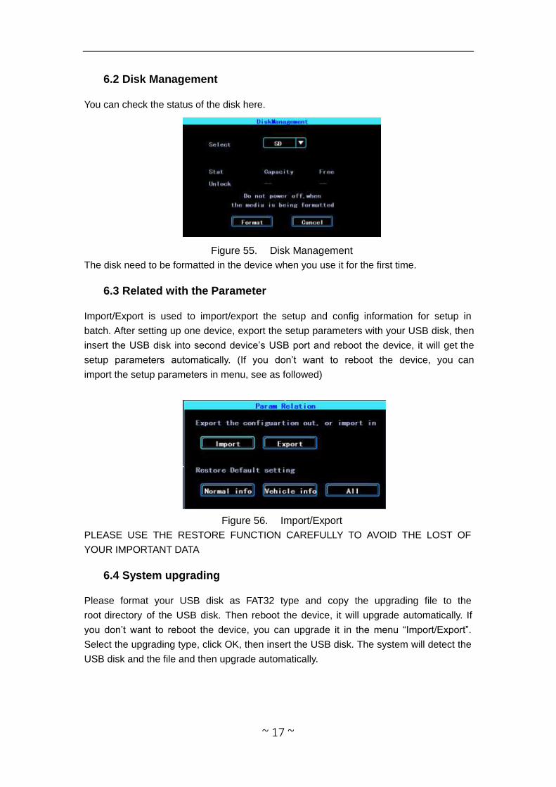
6.2 Disk Management
You can check the status of the disk here.
Figure 55. Disk Management
The disk need to be formatted in the device when you use it for the first time.
6.3 Related with the Parameter
Import/Export is used to import/export the setup and config information for setup in
batch. After setting up one device, export the setup parameters with your USB disk, then insert the USB disk into second device’s USB port and reboot the device, it will get the
setup parameters automatically. (If you don’t want to reboot the device, you can
import the setup parameters in menu, see as followed)
Figure 56. Import/Export
PLEASE USE THE RESTORE FUNCTION CAREFULLY TO AVOID THE LOST OF
YOUR IMPORTANT DATA
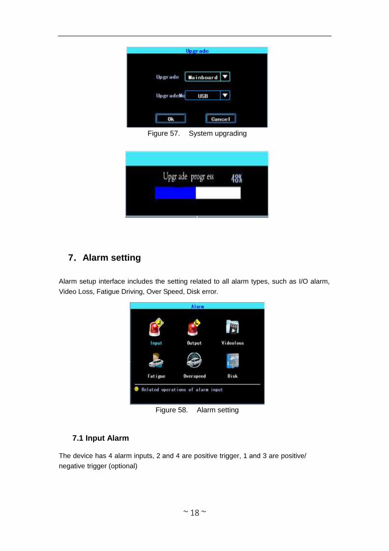
6.4 System upgrading
Please format your USB disk as FAT32 type and copy the upgrading file to the
root directory of the USB disk. Then reboot the device, it will upgrade automatically. If you don’t want to reboot the device, you can upgrade it in the menu “Import/Export”. Select the upgrading type, click OK, then insert the USB disk. The system will detect the
USB disk and the file and then upgrade automatically.
~ 17 ~
~ 18 ~
Figure 57. System upgrading
7.Alarm setting
Alarm setup interface includes the setting related to all alarm types, such as I/O alarm,
Video Loss, Fatigue Driving, Over Speed, Disk error.
Figure 58. Alarm setting
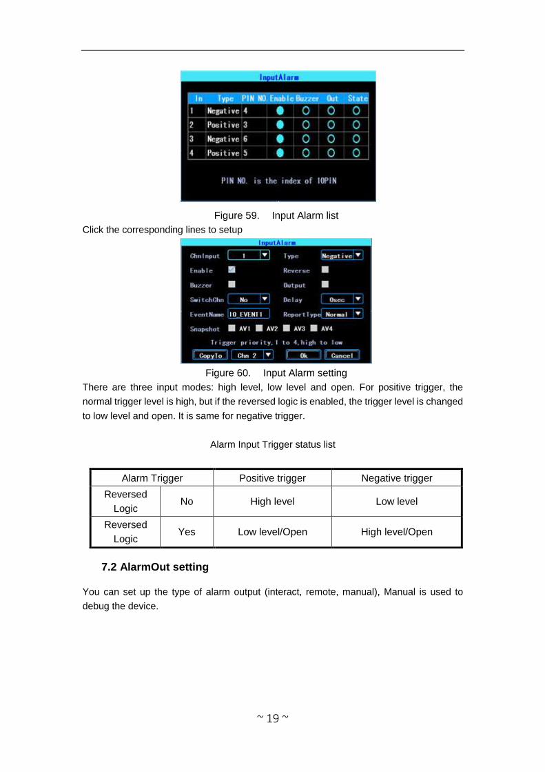
7.1 Input Alarm
The device has 4 alarm inputs, 2 and 4 are positive trigger, 1 and 3 are positive/
negative trigger (optional)
~ 19 ~
Figure 59. Input Alarm list
Click the corresponding lines to setup
Figure 60. Input Alarm setting
There are three input modes: high level, low level and open. For positive trigger, the
normal trigger level is high, but if the reversed logic is enabled, the trigger level is changed
to low level and open. It is same for negative trigger.
Alarm Input Trigger status list
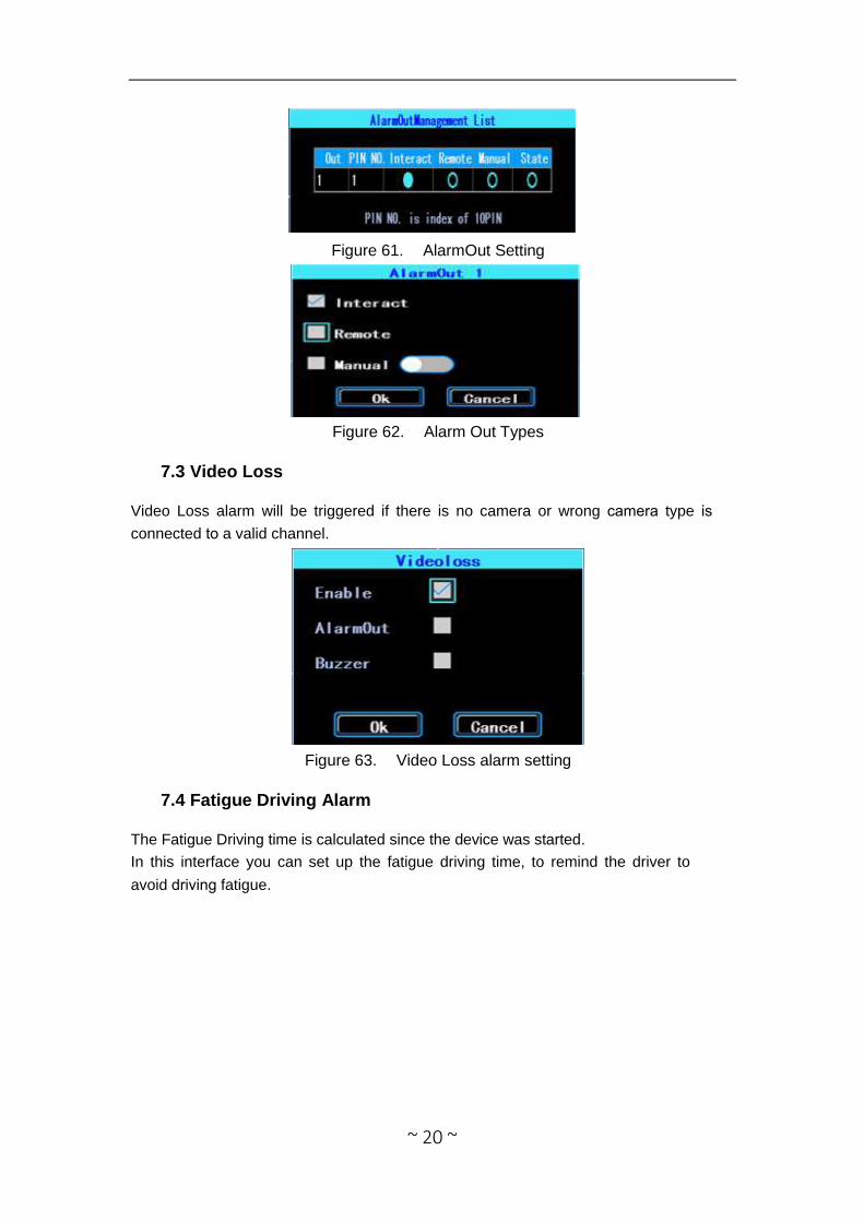
7.2 AlarmOut setting
You can set up the type of alarm output (interact, remote, manual), Manual is used to
debug the device.
Alarm Trigger Positive trigger Negative trigger
Reversed
Logic No High level Low level
Reversed
Logic Yes Low level/Open High level/Open
~ 20 ~
Figure 61. AlarmOut Setting
Figure 62. Alarm Out Types
7.3 Video Loss
Video Loss alarm will be triggered if there is no camera or wrong camera type is
connected to a valid channel.
Figure 63. Video Loss alarm setting
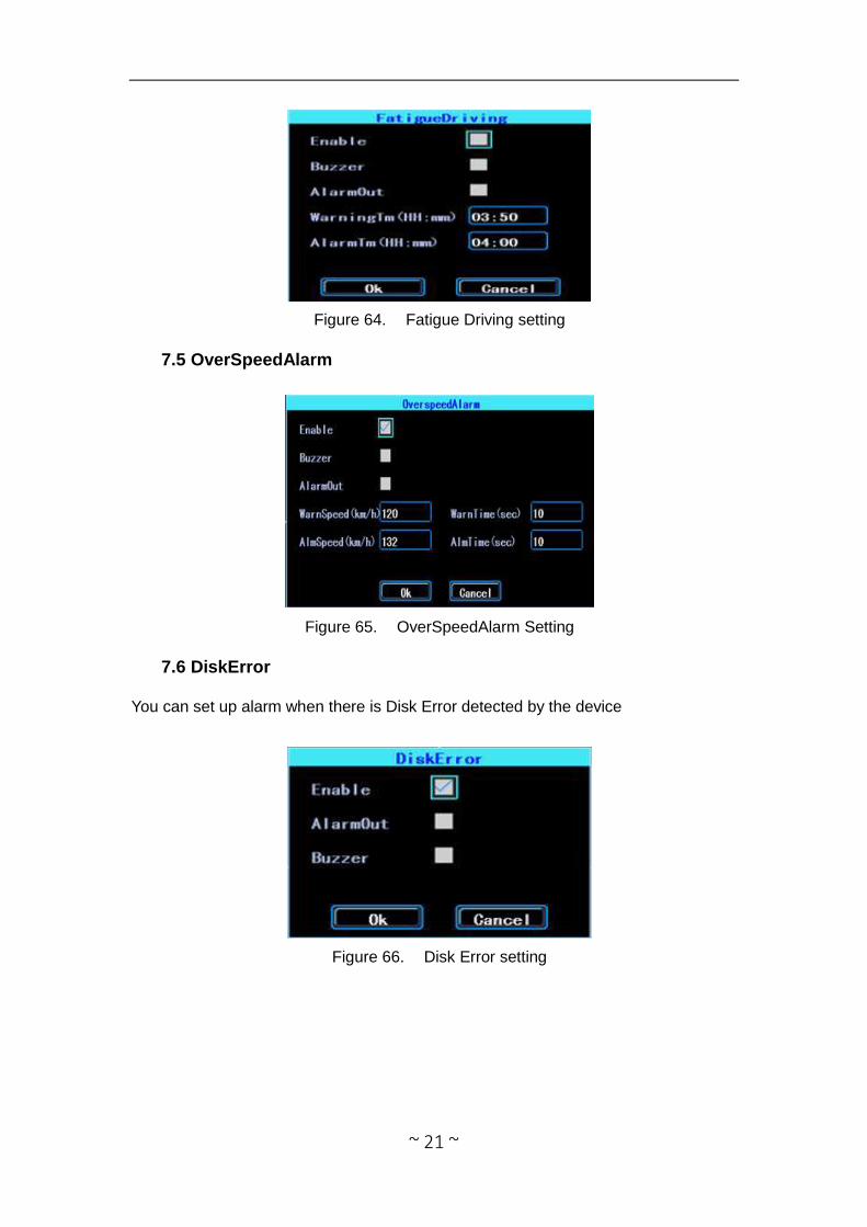
7.4 Fatigue Driving Alarm
The Fatigue Driving time is calculated since the device was started.
In this interface you can set up the fatigue driving time, to remind the driver to
avoid driving fatigue.
~ 21 ~
Figure 64. Fatigue Driving setting
7.5 OverSpeedAlarm
Figure 65. OverSpeedAlarm Setting
7.6 DiskError
You can set up alarm when there is Disk Error detected by the device
Figure 66. Disk Error setting
~ 22 ~
Chapter 4 Installation Warnings
1. When you received the product, please open the box and check the device and
accessories. If there is anything damaged or missing, please contact your seller.
2. When installing and operating the device, please check the standard of all
electronics and the connections to the vehicle and other devices
3. Please double check the input power voltage, it should be 8-36V DC, to avoid the
damage caused by wrong voltage.
4.The device should be install in a location away from extreme heat and humidity.
5. Allow for adequate airflow around the device.
6. Installation should be done in compliance with the local, state, and federal regulations.

IMPORTANT
If you are having difficulties with the installation
of this product, please call our Tech Support line
at 1-800-253-TECH. Before doing so, look over
the instructions a second time, and make sure
the installation was performed exactly as the
instructions are stated. Please have the vehicle
apart and ready to perform troubleshooting
steps before calling.
When connecting with power cable, please make sure not to mistake the positive and negative pole, otherwise the fuse will blow immediately for security protection. If it happens,please replace the blown fuse with a new one with same specification, after connectingproperly to the right pole. Don’t randomly increase the current rating of the fuse, and NEVERuse metal wire as a substitute.
KNOWLEDGE IS POWER
Enhance your installation and fabrication skills by
enrolling in the most recognized and respected mobile
electronics school in our industry.
Log onto www.installerinstitute.com or call
800-354-6782 for more information and take steps
toward a better tomorrow.
Metra recommends MECP
certified technicians
Version 1.0