Embed Size (px)
Citation preview
AC 2010-2249: TEACHING PLCS USING THE KOLB LEARNING CYCLE
Nebojsa Jaksic, Colorado State University, PuebloNebojsa I. Jaksic received the Dipl. Ing. degree in electrical engineering from BelgradeUniversity in 1984, the M.S. in electrical engineering, the M.S. in industrial engineering, and thePh.D. in industrial engineering from the Ohio State University in 1988, 1992, and 2000,respectively.
From 1992 to 2000 he was with DeVry University in Columbus, OH. In 2000, he joined ColoradoState University-Pueblo, where he is currently an Associate Professor and the mechatronicsprogram director. Dr. Jaksic's interests include manufacturing processes, automation, andnanotechnology education and research. He is a member of ASEE, IEEE, SME, and MRS.
© American Society for Engineering Education, 2010
Page 15.1183.1
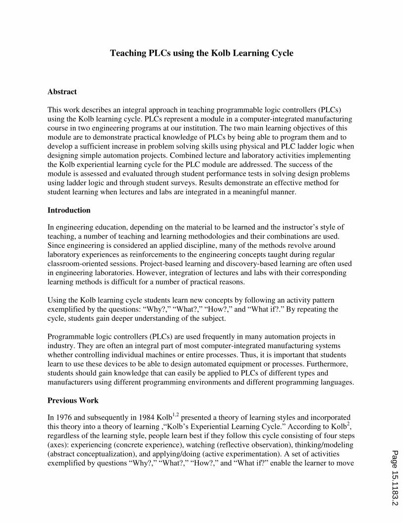
Teaching PLCs using the Kolb Learning Cycle
Abstract
This work describes an integral approach in teaching programmable logic controllers (PLCs)
using the Kolb learning cycle. PLCs represent a module in a computer-integrated manufacturing
course in two engineering programs at our institution. The two main learning objectives of this
module are to demonstrate practical knowledge of PLCs by being able to program them and to
develop a sufficient increase in problem solving skills using physical and PLC ladder logic when
designing simple automation projects. Combined lecture and laboratory activities implementing
the Kolb experiential learning cycle for the PLC module are addressed. The success of the
module is assessed and evaluated through student performance tests in solving design problems
using ladder logic and through student surveys. Results demonstrate an effective method for
student learning when lectures and labs are integrated in a meaningful manner.
Introduction
In engineering education, depending on the material to be learned and the instructor’s style of teaching, a number of teaching and learning methodologies and their combinations are used.
Since engineering is considered an applied discipline, many of the methods revolve around
laboratory experiences as reinforcements to the engineering concepts taught during regular
classroom-oriented sessions. Project-based learning and discovery-based learning are often used
in engineering laboratories. However, integration of lectures and labs with their corresponding
learning methods is difficult for a number of practical reasons.
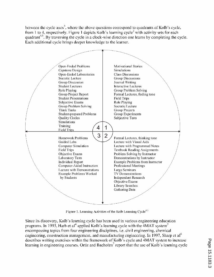
Using the Kolb learning cycle students learn new concepts by following an activity pattern
exemplified by the questions: “Why?,” “What?,” “How?,” and “What if?.” By repeating the
cycle, students gain deeper understanding of the subject.
Programmable logic controllers (PLCs) are used frequently in many automation projects in
industry. They are often an integral part of most computer-integrated manufacturing systems
whether controlling individual machines or entire processes. Thus, it is important that students
learn to use these devices to be able to design automated equipment or processes. Furthermore,
students should gain knowledge that can easily be applied to PLCs of different types and
manufacturers using different programming environments and different programming languages.
Previous Work
In 1976 and subsequently in 1984 Kolb1,2
presented a theory of learning styles and incorporated
this theory into a theory of learning ,“Kolb’s Experiential Learning Cycle.” According to Kolb2,
regardless of the learning style, people learn best if they follow this cycle consisting of four steps
(axes): experiencing (concrete experience), watching (reflective observation), thinking/modeling
(abstract conceptualization), and applying/doing (active experimentation). A set of activities
exemplified by questions “Why?,” “What?,” “How?,” and “What if?” enable the learner to move
Page 15.1183.2
Page 15.1183.3
in aeronautical, mechanical and civil engineering programs reduces learning time (opposite Harb
et al4) and improves students’ interest, class attendance and course completion. Wyrick and
Hilsen8 applied Kolb’s cycle in an industrial engineering program spanning four courses and
analyzing ten years of data. They report deep learning and warn faculty of lower-than-usual
student course evaluations. Harding et al9 describe use of Kolb’s cycle in a Materials and Process
Selection course within their manufacturing engineering program. In 2009, Abdulwahed and
Nagy10
implemented Kolb’s cycle in process control laboratory within a chemical engineering
program.
Most of the engineering education research on Kolb’s cycle deals with implementations of this
learning method in different engineering course environments. However, there seems to be little
formal quantitative assessment/evaluation reported. Gains in content knowledge don’t seem to be
significant, while “deep knowledge” is not measured quantitatively.
Curriculum Context
The activities described in Figure 1 are applied in a required computer-integrated manufacturing
(CIM) course at our university in two engineering programs: the Industrial Engineering and the
Bachelor of Science in Engineering with Specialization in Mechatronics. The CIM course is a
senior-level design-based course dealing with modern technologies such as automation, digital
controllers, programmable logical controllers (PLCs), computer-numerically controlled (CNC)
machines, and robotics. The CIM laboratory curriculum includes hands-on experiences with
simple digital controllers, PLCs, CNC mills, and robots. PLCs are industrial grade computers
used extensively in automation. In this study, we concentrate on the PLC experience. Laboratory
exercises are developed to enable students to learn and to enhance their problem-solving skills
using familiar design situations.
PLC Module Description
Since the lectures and the experiments are integrated the module is described within the context
of Kolb’s cycles. In general, for five weeks, students learn ladder logic (both physical and PLC),
pneumatic and hydraulic circuits, switches and sensors in the classroom and in the laboratory.
The course philosophy is such that ladder logic diagrams with simple inputs and outputs are used
so to keep the diagrams and the designs independent of PLC types as much as possible. While
the concepts are relatively simple, the design applications can be quite complicated and complex.
There are four laboratory exercises. One exercise is used to enable students to effectively use the
PLC graphical user interface and the PLC programming environment. The remaining three
laboratory exercises represent the design problems of increasing difficulty. One homework
assignment and two tests (a module test and a comprehensive final test) are implemented as
learning tools and to evaluate the “deep learning” component of the PLC design skills.
Experimental Setups
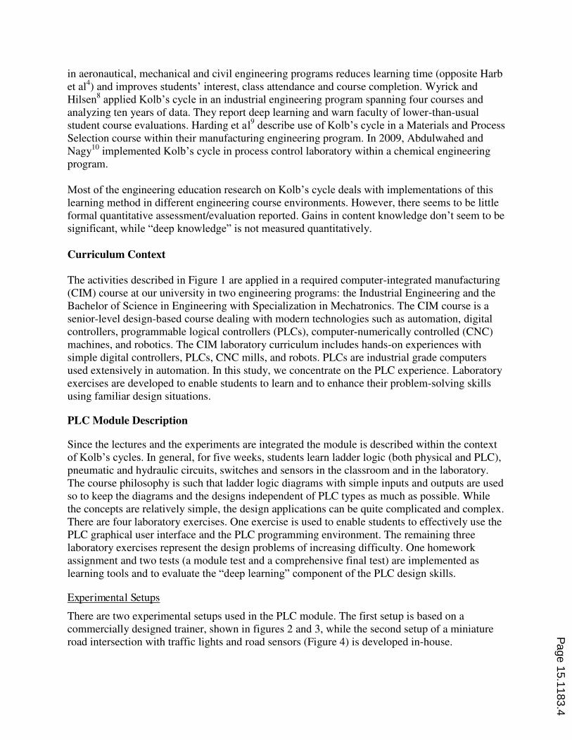
There are two experimental setups used in the PLC module. The first setup is based on a
commercially designed trainer, shown in figures 2 and 3, while the second setup of a miniature
road intersection with traffic lights and road sensors (Figure 4) is developed in-house.
Page 15.1183.4
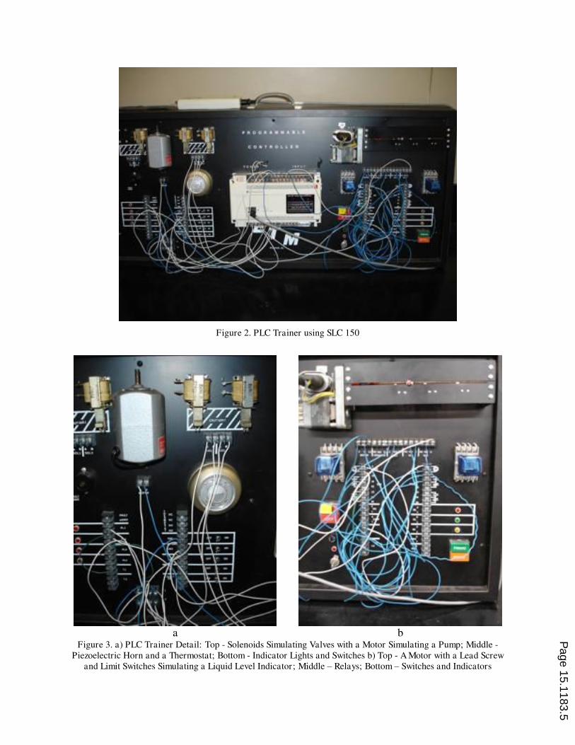
Figure 2. PLC Trainer using SLC 150
a b
Figure 3. a) PLC Trainer Detail: Top - Solenoids Simulating Valves with a Motor Simulating a Pump; Middle -
Piezoelectric Horn and a Thermostat; Bottom - Indicator Lights and Switches b) Top - A Motor with a Lead Screw
and Limit Switches Simulating a Liquid Level Indicator; Middle – Relays; Bottom – Switches and Indicators
Page 15.1183.5
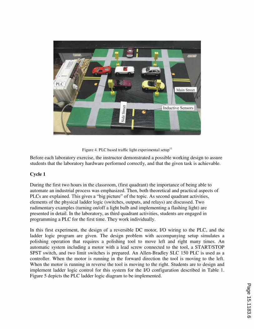
Figure 4. PLC based traffic light experimental setup11
Before each laboratory exercise, the instructor demonstrated a possible working design to assure
students that the laboratory hardware performed correctly, and that the given task is achievable.
Cycle 1
During the first two hours in the classroom, (first quadrant) the importance of being able to
automate an industrial process was emphasized. Then, both theoretical and practical aspects of
PLCs are explained. This gives a “big picture” of the topic. As second quadrant activities,
elements of the physical ladder logic (switches, outputs, and relays) are discussed. Two
rudimentary examples (turning on/off a light bulb and implementing a flashing light) are
presented in detail. In the laboratory, as third quadrant activities, students are engaged in
programming a PLC for the first time. They work individually.
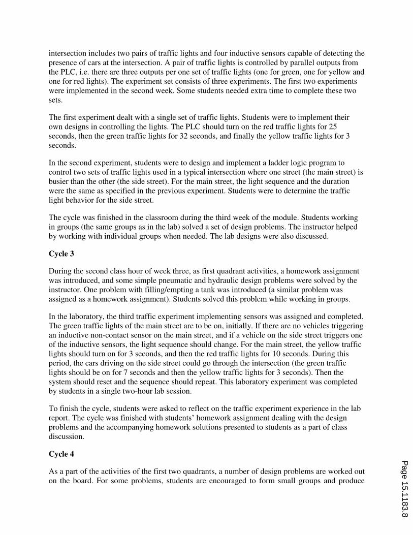
In this first experiment, the design of a reversible DC motor, I/O wiring to the PLC, and the
ladder logic program are given. The design problem with accompanying setup simulates a
polishing operation that requires a polishing tool to move left and right many times. An
automatic system including a motor with a lead screw connected to the tool, a START/STOP
SPST switch, and two limit switches is prepared. An Allen-Bradley SLC 150 PLC is used as a
controller. When the motor is running in the forward direction the tool is moving to the left.
When the motor is running in reverse the tool is moving to the right. Students are to design and
implement ladder logic control for this system for the I/O configuration described in Table 1.
Figure 5 depicts the PLC ladder logic diagram to be implemented.
Page 15.1183.6
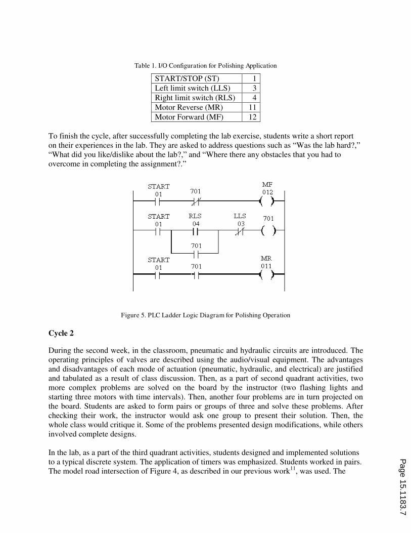
Table 1. I/O Configuration for Polishing Application
START/STOP (ST) 1
Left limit switch (LLS) 3
Right limit switch (RLS) 4
Motor Reverse (MR) 11
Motor Forward (MF) 12
To finish the cycle, after successfully completing the lab exercise, students write a short report
on their experiences in the lab. They are asked to address questions such as “Was the lab hard?,”
“What did you like/dislike about the lab?,” and “Where there any obstacles that you had to
overcome in completing the assignment?.”
Figure 5. PLC Ladder Logic Diagram for Polishing Operation
Cycle 2
During the second week, in the classroom, pneumatic and hydraulic circuits are introduced. The
operating principles of valves are described using the audio/visual equipment. The advantages
and disadvantages of each mode of actuation (pneumatic, hydraulic, and electrical) are justified
and tabulated as a result of class discussion. Then, as a part of second quadrant activities, two
more complex problems are solved on the board by the instructor (two flashing lights and
starting three motors with time intervals). Then, another four problems are in turn projected on
the board. Students are asked to form pairs or groups of three and solve these problems. After
checking their work, the instructor would ask one group to present their solution. Then, the
whole class would critique it. Some of the problems presented design modifications, while others
involved complete designs.
In the lab, as a part of the third quadrant activities, students designed and implemented solutions
to a typical discrete system. The application of timers was emphasized. Students worked in pairs.
The model road intersection of Figure 4, as described in our previous work11
, was used. The
Page 15.1183.7
intersection includes two pairs of traffic lights and four inductive sensors capable of detecting the
presence of cars at the intersection. A pair of traffic lights is controlled by parallel outputs from
the PLC, i.e. there are three outputs per one set of traffic lights (one for green, one for yellow and
one for red lights). The experiment set consists of three experiments. The first two experiments
were implemented in the second week. Some students needed extra time to complete these two
sets.
The first experiment dealt with a single set of traffic lights. Students were to implement their
own designs in controlling the lights. The PLC should turn on the red traffic lights for 25
seconds, then the green traffic lights for 32 seconds, and finally the yellow traffic lights for 3
seconds.
In the second experiment, students were to design and implement a ladder logic program to
control two sets of traffic lights used in a typical intersection where one street (the main street) is
busier than the other (the side street). For the main street, the light sequence and the duration
were the same as specified in the previous experiment. Students were to determine the traffic
light behavior for the side street.
The cycle was finished in the classroom during the third week of the module. Students working
in groups (the same groups as in the lab) solved a set of design problems. The instructor helped
by working with individual groups when needed. The lab designs were also discussed.
Cycle 3
During the second class hour of week three, as first quadrant activities, a homework assignment
was introduced, and some simple pneumatic and hydraulic design problems were solved by the
instructor. One problem with filling/empting a tank was introduced (a similar problem was
assigned as a homework assignment). Students solved this problem while working in groups.
In the laboratory, the third traffic experiment implementing sensors was assigned and completed.
The green traffic lights of the main street are to be on, initially. If there are no vehicles triggering
an inductive non-contact sensor on the main street, and if a vehicle on the side street triggers one
of the inductive sensors, the light sequence should change. For the main street, the yellow traffic
lights should turn on for 3 seconds, and then the red traffic lights for 10 seconds. During this
period, the cars driving on the side street could go through the intersection (the green traffic
lights should be on for 7 seconds and then the yellow traffic lights for 3 seconds). Then the
system should reset and the sequence should repeat. This laboratory experiment was completed
by students in a single two-hour lab session.
To finish the cycle, students were asked to reflect on the traffic experiment experience in the lab
report. The cycle was finished with students’ homework assignment dealing with the design
problems and the accompanying homework solutions presented to students as a part of class
discussion.
Cycle 4
As a part of the activities of the first two quadrants, a number of design problems are worked out
on the board. For some problems, students are encouraged to form small groups and produce
Page 15.1183.8
group designs. One group is selected to present their design, which is then compared to other
groups’ designs. A design homework assignment dealing with an application of PLCs is assigned, corrected, and then explained in detail in the classroom. In addition, some successful
student designs are emphasized. The laboratory assignment is discussed in the classroom.
Students are asked to come to the lab session with tentative design solutions.
The lab design objective was to develop a PLC ladder logic for a batch process in the chemical
industry to mix two liquids in a tank. The fluids are poured into the tank in precise amounts and
then the mixture is emptied from the tank. According to the I/O specs given, proper wiring
connections were to be made. Students were to implement PLC ladder logic to control the
process. The design used the experimental setup shown in figures 2 and 3. However, the level
indicator was hardware simulated by a motor with two relays for back and forth motion of the
indicator. Limit switches were to present level switches. However, they behave differently than
the real level switches. When the indicator passes by them they de-activate. Most students didn’t account for this in their preliminary designs. They spent two weeks in completing this lab.
During the fifth week of the PLC module, an open-book test was administered. The test
consisted of five design problems. Students in this class performed better than students from the
previous year when the class was offered. The test design problems were used as a learning tool
as well as an evaluation tool. In week six, instructor discussed all the test problems. In lab,
students completed their designs successfully and wrote a short lab report presenting only the
obstacles they had to overcome to complete the design and reflections on what they learned.
At the end of the course, a final test including two design problems dealing with PLCs was
administered. Almost all students’ designs were acceptable.
Analysis and Results
Two types of analyses/results are presented: one dealing with the learning objectives, and
another one dealing with the student perceptions of Kolb’s cycle procedure/results. The
implementation of Kolb’s learning cycle increased slightly the PLC test average from 67.8% to
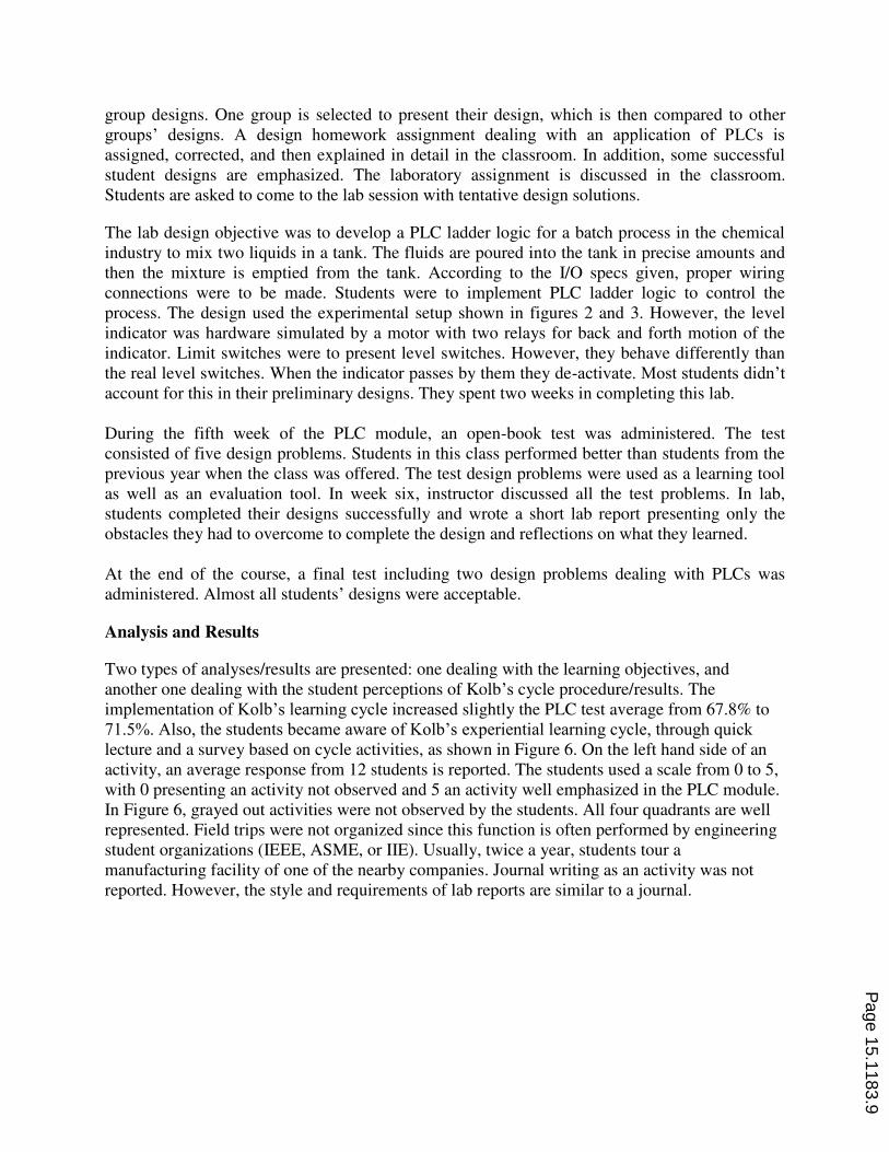
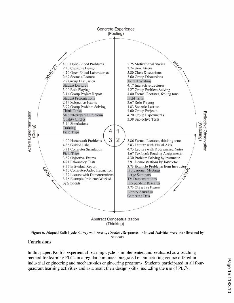
71.5%. Also, the students became aware of Kolb’s experiential learning cycle, through quick lecture and a survey based on cycle activities, as shown in Figure 6. On the left hand side of an
activity, an average response from 12 students is reported. The students used a scale from 0 to 5,
with 0 presenting an activity not observed and 5 an activity well emphasized in the PLC module.
In Figure 6, grayed out activities were not observed by the students. All four quadrants are well
represented. Field trips were not organized since this function is often performed by engineering
student organizations (IEEE, ASME, or IIE). Usually, twice a year, students tour a
manufacturing facility of one of the nearby companies. Journal writing as an activity was not
reported. However, the style and requirements of lab reports are similar to a journal.
Page 15.1183.9
Page 15.1183.10
improved. Furthermore, at the end of the module, students learned how to implement Kolb’s learning cycle on their own, through lecture and by filling a survey. Future developments will
include an implementation and assessment of Kolb’s cycle in the remaining modules of the course. If proven successful, the entire manufacturing course sequence will be modified to
complement this learning method. It is expected that the long-lasting effects of the Kolb’s cycle implementation will result in positive changes in students’, and later engineers’, approaches to learning.
Bibliography
1. Kolb, D. A., “Management and Learning Processes,” California Management Review, Vol. 18, No. 3, 1976, pp.
21-31.
2. Kolb, D. A., Experiential Learning: Experience as the Source of Learning and Development, Prentice Hall,
Englewood Cliffs, N.J., 1984.
3. McCarthy, B., The 4MAT System: Teaching to Learning Styles with Right/Left Mode Techniques, EXCEL, Inc.,
1987.
4. Harb, J. N., Durrant, S. O., and Terry, R. E., ”Use of the Kolb Learning Cycle and the 4MAT System in
Engineering in Education,” Journal of Engineering Education, Vol. 82, April 1993, pp. 70-77.
5. Harb, J. N., Terry, R. E., Hurt, P. K., and Williamson, K. J., Teaching Through The Cycle: Application of
Learning Style Theory to Engineering Education at Brigham Young University, 2nd
Edition, Brigham Young
University Press, 1995.
6. Sharp, J. E., Harb, J. N., and Terry, R. E., Combining Kolb Learning Styles and Writing to Learn in
Engineering Classes, Journal of Engineering Education,April 1997, pp. 93-101.
7. Ortiz, L. E. and Bachofen, E. M., “An Experience in Teaching Structures in Aeronautical, Mechanical and Civil Engineering, Applying the Experimental Methodology,” Proceedings of the 2001 American Society for
Engineering Education Annual Conference & Exposition, Session 2526.
8. Wyrick, D. A. and Hilsen, L., “Using Kolb’s Cycle to Round Out Learning,” 2002 American Society for
Engineering Education Annual Conference and Exposition Proceedings, Montreal, Canada, June 17-19, 2002.
Session 2739.
9. Harding, T. S., Lai, H.-Y., Tuttle, B. L., and White, C. V., “Integrating Manufacturing, Design and Teamwork into a Materials and Processes Selection Course,” 2002 American Society for Engineering Education Annual
Conference and Exposition Proceedings, Montreal, Canada, June 17-19, 2002. Session 1526.
10. Abdulwahed, M. and Nagy, Z. K., Applying Kolb’s Experiential Learning Cycle for Laboratory Education, Journal of Engineering Education, July 2009, pp. 283-294.
11. Jaksic, N. “Improving Self-Efficacy in Engineering Students using PLC Based Traffic Light Experiments,”
2002 American Society for Engineering Education Annual Conference and Exposition Proceedings, Montreal,
Canada, June 17-19, 2002.
Page 15.1183.11