Embed Size (px)
Citation preview
Objective
Today’s transportation professionals, with limited resources available to them, are challenged to meet the mobility needs of an increasing popula- tion. At many highway junctions, congestion con-tinues to worsen, and drivers, pedestrians, and bicyclists experience increasing delays and height- ened exposure to risk. Today’s traffic volumes and travel demands often lead to safety problems that are too complex for conventional inter-section designs to properly handle. Consequently, more engineers are consid-ering various inno-vative treatments as they seek solutions to these complex problems.
The corresponding report, AlternativeIntersections/Interch-anges: Informational Report (AIIR) (FHWA-HRT-09-060), covers four intersection des- igns and two interch-ange designs that offer substantial adv- antages over conven- tional at-grade inter- sections and grade- separated diamond
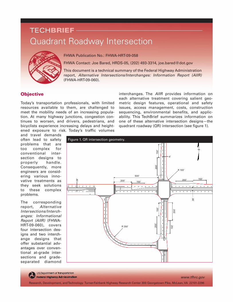
interchanges. The AIIR provides information oneach alternative treatment covering salient geo- metric design features, operational and safety issues, access management, costs, construction sequencing, environmental benefits, and applic- ability. This TechBrief summarizes information on one of these alternative intersection designs—the quadrant roadway (QR) intersection (see figure 1).
Research, Development, and Technology Turner-Fairbank Highway Research Center 300 Georgetown Pike, McLean, VA 22101-2296
www.tfhrc.gov
TECHBRIEF
FHWA Publication No.: FHWA-HRT-09-058
FHWA Contact: Joe Bared, HRDS-05, (202) 493-3314, [email protected]
This document is a technical summary of the Federal Highway Administration report, Alternative Intersections/Interchanges: Information Report (AIIR) (FHWA-HRT-09-060).
Quadrant Roadway Intersection
Figure 1. QR intersection geometry.
200’
150’
500’
200’ 150’200’ 150’
200’
200’15
0’
150’R 250’
R 100’
4’
28’
28’
2
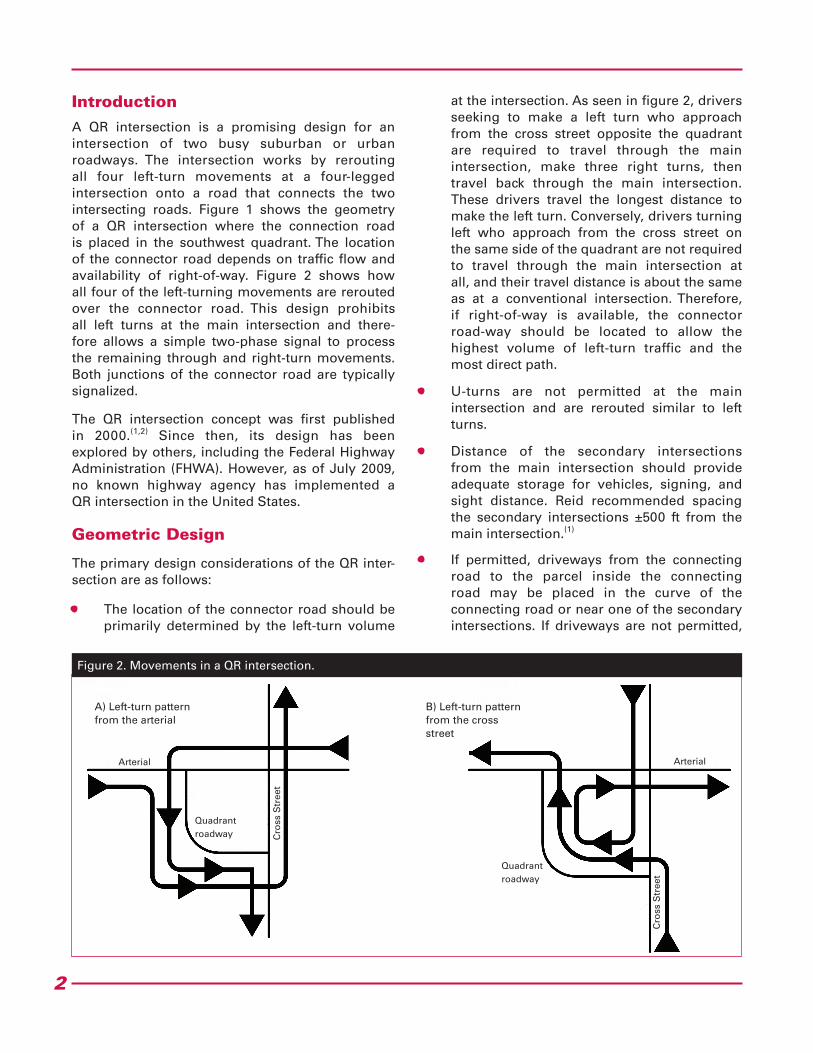
IntroductionA QR intersection is a promising design for an intersection of two busy suburban or urban roadways. The intersection works by rerouting all four left-turn movements at a four-legged intersection onto a road that connects the two intersecting roads. Figure 1 shows the geometry of a QR intersection where the connection road is placed in the southwest quadrant. The location of the connector road depends on traffic flow and availability of right-of-way. Figure 2 shows how all four of the left-turning movements are rerouted over the connector road. This design prohibits all left turns at the main intersection and there-fore allows a simple two-phase signal to process the remaining through and right-turn movements. Both junctions of the connector road are typically signalized.
The QR intersection concept was first published in 2000.(1,2) Since then, its design has been explored by others, including the Federal Highway Administration (FHWA). However, as of July 2009, no known highway agency has implemented a QR intersection in the United States.
Geometric Design
The primary design considerations of the QR inter-section are as follows:
• The location of the connector road should be primarily determined by the left-turn volume
at the intersection. As seen in figure 2, drivers seeking to make a left turn who approach from the cross street opposite the quadrant are required to travel through the main intersection, make three right turns, then travel back through the main intersection. These drivers travel the longest distance to make the left turn. Conversely, drivers turning left who approach from the cross street on the same side of the quadrant are not required to travel through the main intersection at all, and their travel distance is about the same as at a conventional intersection. Therefore, if right-of-way is available, the connector road-way should be located to allow the highest volume of left-turn traffic and the most direct path.
• U-turns are not permitted at the main intersection and are rerouted similar to left turns.
• Distance of the secondary intersections from the main intersection should provide adequate storage for vehicles, signing, and sight distance. Reid recommended spacing the secondary intersections ±500 ft from the main intersection.(1)
• If permitted, driveways from the connecting road to the parcel inside the connecting road may be placed in the curve of the connecting road or near one of the secondary intersections. If driveways are not permitted,
Figure 2. Movements in a QR intersection.
A) Left-turn pattern from the arterial
B) Left-turn pattern from the cross street
Arterial Arterial
Quadrant roadway
Quadrant roadway
Cro
ss S
tree
t
Cro
ss S
tree
t
3
then the parcel inside the connecting road-way can be accessed via driveways off one or both of the intersecting streets.
• At a QR intersection, some pedestrians will need to cross an extra street; however, others who follow the curved connection roadway or the main intersection crosswalks will have shorter walking distances. Also, the shorter cycle lengths at QR intersections benefit pedestrians.
• A QR with more than one connection road can be implemented if right-of-way is available and if left-turn volumes justify it. Geometric principles remain largely the same for QRs with one or more connection roadways.
Traffic Signal Control
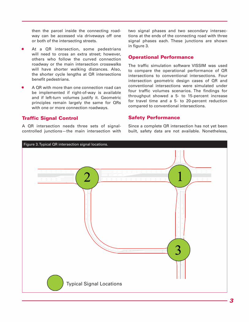
A QR intersection needs three sets of signal- controlled junctions—the main intersection with
two signal phases and two secondary intersec-tions at the ends of the connecting road with three signal phases each. These junctions are shown in figure 3.
Operational Performance
The traffic simulation software VISSIM was used to compare the operational performance of QR intersections to conventional intersections. Four intersection geometric design cases of QR and conventional intersections were simulated under four traffic volumes scenarios. The findings for throughput showed a 5- to 15-percent increase for travel time and a 5- to 20-percent reduction compared to conventional intersections.
Safety Performance
Since a complete QR intersection has not yet been built, safety data are not available. Nonetheless,
Figure 3. Typical QR intersection signal locations.
Typical Signal Locations
4
Researchers—This study was performed by Principal Investigators Warren Hughes and Ram Jagannathan. For more information about this research, contact Joe Bared, FHWA Project Manager, HRDS-05 at (202) 493-3314, [email protected].
Distribution—This TechBrief is being distributed according to a standard distribution. Direct distribution is being made to the Divisions and Resource Center.
Availability—This TechBrief may be obtained from the FHWA Product Distribution Center by e-mail to [email protected], fax to (814) 239-2156, phone to (814) 239-1160, or online at http://www.tfhrc.gov/safety.
Key Words—Quadrant roadway intersection, QRI, QR, and Alternative intersection.
Notice—This document is disseminated under the sponsorship of the U.S. Department of Transportation in the interest of information exchange. The U.S. Government assumes no liability for the use of the information contained in this document. The U.S. Government does not endorse products or manufacturers. Trademarks or manufacturers’ names appear in this report only because they are considered essential to the objective of the document.
Quality Assurance Statement—The Federal Highway Administration (FHWA) provides high-quality informa-tion to serve the Government, industry, and public in a manner that promotes public understanding. Standards and policies are used to ensure and maximize the quality, objectivity, utility, and integrity of its information. FHWA periodically reviews quality issues and adjusts its programs and processes to ensure continuous quality improvement.
OCTOBeR 2009 FHWA-HRT-09-058
HRDS-05/10-09(3M)e
the QR has 28 conflict points more widely spread out than compared to 32 at a conventional inter-section. This reduction in conflict points suggests the QR may be safer, although a definitive relation-ship between conflicts and safety has not yet been established.
Applicability
QR intersections will typically be spot treatments. They are most applicable where the following exists:
• A roadway in the road network can be used as a connection roadway.
• There are heavy left turns and through vol-umes on the major and minor roads.
• The minor road total volume to total inter-section volume ratio is typically less than or equal to 0.35.
SummaryThe QR intersection increases operational efficiency through a congested intersection by moving the left turns away from the main intersection and allowing a two-phase signal at
the main intersection. While additional right-of- way would be needed in the connection road quadrant, and extra cost would be necessary to build the connecting roadway, the QR intersec-tion could be used to reduce congestion at a busy intersection in a developing area. It could also serve as a temporary congestion reliever until a grade-separated solution can be built. In addition, the QR intersection accommodates pedestrians well. More details can be found in the full AIIR available from the FHWA.
References
1. Reid, J.D. (2000). “Using Quadrant Roadways to Improve Arterial Intersection Operations,” ITE Journal, 70(6), 34–45.
2. Reid, J.D. and Hummer, J.e. (2001). “Travel Time Comparisons Between Seven Unconven-tional Arterial Intersection Designs,” Transportation Research Record 1751, 56–66.