Embed Size (px)
Citation preview
11.29.2010 Technical Report 3 Matthew Geary
1 Butler Memorial Hospital | New Inpatient Tower – Senior Capstone Project – Mechanical Option Advisor: Dr. William Bahnfleth
Technical Assignment 3
Mechanical Systems and Existing Conditions
Butler Memorial Hospital | New Inpatient Tower
Butler Healthcare Providers
Butler, PA
11.29.2010 Technical Report 3 Matthew Geary
2 Butler Memorial Hospital | New Inpatient Tower – Senior Capstone Project – Mechanical Option Advisor: Dr. William Bahnfleth
Table of Contents
Executive Summary................................................................................................ 3
Mechanical Summary ............................................................................................ 4
Introduction .............................................................................................................................................. 4
Design Criteria ........................................................................................................................................... 4
Design Conditions ..................................................................................................................................... 5
Ventilation Requirements ......................................................................................................................... 6
Mechanical Equipment Summary ............................................................................................................. 6
Mechanical System 1st Costs ..................................................................................................................... 9
Lost Usable Space ................................................................................................................................... 10
System Operation ................................................................................................ 10
Air Side Control ....................................................................................................................................... 10
Water Side ............................................................................................................................................... 11
Building Performance .......................................................................................... 15
Thermal Loads ......................................................................................................................................... 15
Energy Consumption ............................................................................................................................... 17
LEED-NC Analysis ................................................................................................. 19
Energy and Atmosphere ......................................................................................................................... 19
Indoor Environmental Quality ................................................................................................................ 20
Overall Evaluation Summary ................................................................................ 21
APPENDIX A: List of Tables and Figures ................................................................ 23
List of Tables ........................................................................................................................................... 24
List of Figures .......................................................................................................................................... 24
11.29.2010 Technical Report 3 Matthew Geary
3 Butler Memorial Hospital | New Inpatient Tower – Senior Capstone Project – Mechanical Option Advisor: Dr. William Bahnfleth
Executive Summary
The New Inpatient Tower at the Butler Memorial Hospital is a 209,000 square foot addition
seated in Butler, Pennsylvania that has just been completed in July 2010. The eight story tower was
built to house state of the art operating and recovery rooms.
The primary means of heating, ventilation, and air-conditioning is done through the variable air
volume system with reheat at the terminal boxes and supplementary finned tube radiation heating coils
at the perimeter of patient rooms. When designing the mechanical systems in the building, engineers
chose a VAV system because of its relatively low first cost, reliability, and simplistic design. Ventilation
requirements according to ASHRAE Standard 62.1 require 16,000 CFM and were easily met by the design
which introduces 54,000 CFM of ventilation air at design loads.
After doing a preliminary energy model of the building using Trance Trace 700, it was found that
designers oversized all equipment by almost 100% and methods to make the hospital more efficient are
undoubtedly possible. The operating costs of the hospital addition estimated by the computer software
was roughly $290,000 per year with $100,000 of that being attributed to the mechanical systems.
Engineers and designers did not perform an energy analysis of the building and utility bills were not
made available, therefore there is no basis to compare the energy model results against. The building is
not LEED certified and therefore did not require an energy model; however, a preliminary analysis found
that the building is eligible to receive 8 out of a possible 44 credits for the mechanical system design.
The hospital addition features (2) primary chillers and (2) primary boilers which supply chilled
and hot water to the air handlers. Both systems rely on a primary/secondary pumping arrangement to
circulate the water flow. The hot water system also features inline hot water pumps at the heating coil
to help modulate flows. A third chiller, independent of the others serves the (8) operating rooms. A
more detailed summary of the mechanical system and the associated costs are reviewed in more depth
on the following pages.
11.29.2010 Technical Report 3 Matthew Geary
4 Butler Memorial Hospital | New Inpatient Tower – Senior Capstone Project – Mechanical Option Advisor: Dr. William Bahnfleth
Mechanical Summary
Introduction
The New Inpatient Tower at the Butler Memorial Hospital serves as the newest attraction to the
hospital, and at 209,000 square feet of space it houses much of the hospital’s activity. The new tower
includes many public spaces including a chapel, retail space, a café, waiting areas, and conference rooms
on the main level. Below the main level is mostly mechanical space and storage; however, the focal
point of the tower lies on the floor above. Eight state of the art operating rooms are the main attraction
of the entire addition. The remainder of the tower is comprised of recovery rooms, critical care units,
and patient rooms for those recovering from surgery.
Design Criteria
When designing the New Inpatient Tower, engineers and architects took a very direct approach:
build a patient tower that will be energy efficient, reliable, and comfortable to patients and families.
When designing the HVAC systems, reliability and comfort were the two most important factors. Any
HVAC system looks to provide comfortable temperature and humidity levels, which this system easily
accomplishes. Every main piece of equipment within the mechanical system has inherent redundancy.
Due to the loop system and other design specifications, the hospital can lose an air handler, cooling
tower, primary pump, secondary pump, chiller, or boiler and is still able to meet the majority of loads
under normal operating conditions. It should be noted that there were no design influences based upon
the site, rebates, or tax relief.
Due to the nature of the hospital, a great deal of the thermal and energy loads are a direct
effect of lighting and hospital equipment operation. Both of these areas are essential for the tower to
function and are fairly constant loads. Variable loads which occur are due to infiltration, conditioning of
ventilation air, solar gain, and mechanical equipment loads.
Designers oversized the outside air fraction to ensure proper indoor air quality providing
patients and staff with high quality supply air. The building is designed for every space to receive 33%
outside air at design loads. The minimum ventilation rates used by engineers also significantly exceeds
ASHRAE Standard 62.1, reinforcing the fact that air quality within the tower is a large concern.
Solar gain during the cooling season is not a large problem for the inpatient tower. The hospital
design is fairly conservative when it comes to fenestration, which will lower the effects of solar gain.
Also, the majority of fenestration is located on the North and Northwest facades of the building with
only a small portion of exterior glass occurring along the southern face.
11.29.2010 Technical Report 3 Matthew Geary
5 Butler Memorial Hospital | New Inpatient Tower – Senior Capstone Project – Mechanical Option Advisor: Dr. William Bahnfleth
Mechanical equipment operation accounts for a large portion of the overall energy
consumption. The system could very well be sized down to become more efficient, however design
engineers were more focused and reliability and redundancy than efficiency. This approach is
understandable since there will be human lives in jeopardy every day, demanding certain environmental
conditions for the best chance of survival.
An extremely important facet of the hospital design is linked to the (8) operating rooms on the
third floor. These operating rooms are served by two identical air handlers and are 100% redundant in
the case that one air handler malfunctions. The two air handlers are fed by a 120 ton scroll chiller
supplying 34°F chilled water in order to keep the operating rooms at exactly 60°F year round. The
system is backed up by the (2) main chillers in an emergency case. Hepa filters at the terminal boxes
also ensure the highest quality air within the operating rooms.
The mechanical system also had to be designed for the overhanging floor on the third level. As
a result of the third floor overhanging the second, extra thermal loads coming through the floor had to
be accounted for. The perimeter of the tower is also home to the majority of patient rooms and subject
to extra heating loads at the perimeter and windows. In order to give patients thermal control and to
account for the additional envelope loads, designers implemented finned tube radiant coils along the
perimeter of patient rooms and in the floor of the overhanging third level.
Design Conditions
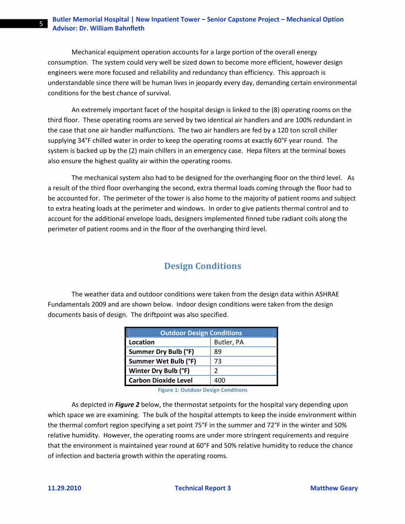
The weather data and outdoor conditions were taken from the design data within ASHRAE
Fundamentals 2009 and are shown below. Indoor design conditions were taken from the design
documents basis of design. The driftpoint was also specified.
Outdoor Design Conditions
Location Butler, PA
Summer Dry Bulb (°F) 89
Summer Wet Bulb (°F) 73
Winter Dry Bulb (°F) 2
Carbon Dioxide Level 400 Figure 1: Outdoor Design Conditions
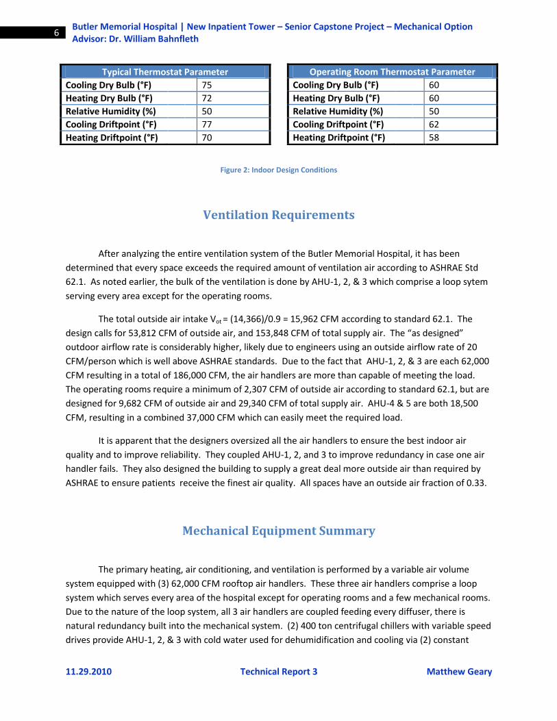
As depicted in Figure 2 below, the thermostat setpoints for the hospital vary depending upon
which space we are examining. The bulk of the hospital attempts to keep the inside environment within
the thermal comfort region specifying a set point 75°F in the summer and 72°F in the winter and 50%
relative humidity. However, the operating rooms are under more stringent requirements and require
that the environment is maintained year round at 60°F and 50% relative humidity to reduce the chance
of infection and bacteria growth within the operating rooms.
11.29.2010 Technical Report 3 Matthew Geary
6 Butler Memorial Hospital | New Inpatient Tower – Senior Capstone Project – Mechanical Option Advisor: Dr. William Bahnfleth
Figure 2: Indoor Design Conditions
Ventilation Requirements
After analyzing the entire ventilation system of the Butler Memorial Hospital, it has been
determined that every space exceeds the required amount of ventilation air according to ASHRAE Std
62.1. As noted earlier, the bulk of the ventilation is done by AHU-1, 2, & 3 which comprise a loop sytem
serving every area except for the operating rooms.
The total outside air intake Vot = (14,366)/0.9 = 15,962 CFM according to standard 62.1. The
design calls for 53,812 CFM of outside air, and 153,848 CFM of total supply air. The “as designed”
outdoor airflow rate is considerably higher, likely due to engineers using an outside airflow rate of 20
CFM/person which is well above ASHRAE standards. Due to the fact that AHU-1, 2, & 3 are each 62,000
CFM resulting in a total of 186,000 CFM, the air handlers are more than capable of meeting the load.
The operating rooms require a minimum of 2,307 CFM of outside air according to standard 62.1, but are
designed for 9,682 CFM of outside air and 29,340 CFM of total supply air. AHU-4 & 5 are both 18,500
CFM, resulting in a combined 37,000 CFM which can easily meet the required load.
It is apparent that the designers oversized all the air handlers to ensure the best indoor air
quality and to improve reliability. They coupled AHU-1, 2, and 3 to improve redundancy in case one air
handler fails. They also designed the building to supply a great deal more outside air than required by
ASHRAE to ensure patients receive the finest air quality. All spaces have an outside air fraction of 0.33.
Mechanical Equipment Summary
The primary heating, air conditioning, and ventilation is performed by a variable air volume
system equipped with (3) 62,000 CFM rooftop air handlers. These three air handlers comprise a loop
system which serves every area of the hospital except for operating rooms and a few mechanical rooms.
Due to the nature of the loop system, all 3 air handlers are coupled feeding every diffuser, there is
natural redundancy built into the mechanical system. (2) 400 ton centrifugal chillers with variable speed
drives provide AHU-1, 2, & 3 with cold water used for dehumidification and cooling via (2) constant
Operating Room Thermostat Parameter
Cooling Dry Bulb (°F) 60
Heating Dry Bulb (°F) 60
Relative Humidity (%) 50
Cooling Driftpoint (°F) 62
Heating Driftpoint (°F) 58
Typical Thermostat Parameter
Cooling Dry Bulb (°F) 75
Heating Dry Bulb (°F) 72
Relative Humidity (%) 50
Cooling Driftpoint (°F) 77
Heating Driftpoint (°F) 70
11.29.2010 Technical Report 3 Matthew Geary
7 Butler Memorial Hospital | New Inpatient Tower – Senior Capstone Project – Mechanical Option Advisor: Dr. William Bahnfleth
volume primary chilled water pumps and (2) VSD secondary pumps. A central rooftop cooling tower
serves as the primary means of cooling the condenser water which exits the two centrifugal chillers.
Rooftop air handling units 4 and 5 are located on a lower level roof (Floor 5) and provide the
necessary heating, ventilating, and air-conditioning to the (8) operating rooms which are located on the
3rd floor. The operating room air handlers are serviced by an adjacent 119 ton air-cooled scroll chiller
supplying 34°F water. The lower temperature system is backed up by the primary chillers in case of
emergency; 45°F primary water can still be supplied. Air Handling Units 6, 7, & 8 are all smaller units
which serve specific mechanical rooms with an extra need for cooling.
On the heating side, (2) 215 BHP combustion gas/oil-fired hot water boilers supply all of the
heating water for the entire building: this includes heating water to the air handling unit heating coils,
unit heaters used for reheat within terminal boxes, duct heating coils, radiant ceiling panels around the
perimeter of patient rooms, and finned tube radiation in the soffit/plenum area above the second floor
to keep the cantilevered floor warm. Two constant volume primary pumps and (2) VSD secondary
pumps circulate the heating water. There are also inline pumps at all heating coils within the various air
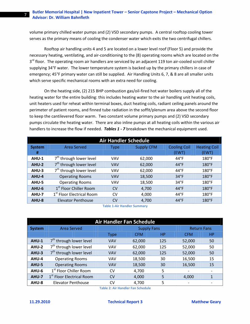
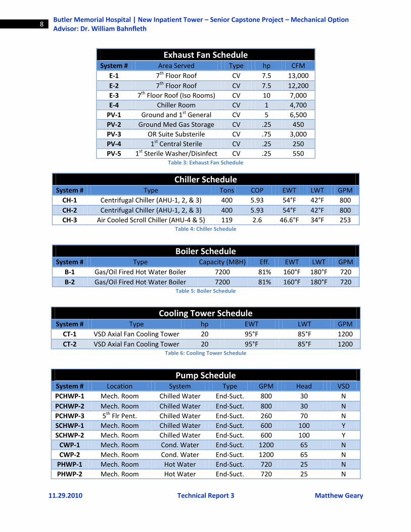
handlers to increase the flow if needed. Tables 1 - 7 breakdown the mechanical equipment used.
Air Handler Schedule System
# Area Served Type Supply CFM Cooling Coil
(EWT) Heating Coil
(EWT)
AHU-1 7th through lower level VAV 62,000 44°F 180°F
AHU-2 7th through lower level VAV 62,000 44°F 180°F
AHU-3 7th through lower level VAV 62,000 44°F 180°F
AHU-4 Operating Rooms VAV 18,500 34°F 180°F
AHU-5 Operating Rooms VAV 18,500 34°F 180°F
AHU-6 1st Floor Chiller Room CV 4,700 44°F 180°F
AHU-7 1st Floor Electrical Room CV 4,000 44°F 180°F
AHU-8 Elevator Penthouse CV 4,700 44°F 180°F Table 1-Air Handler Summary
Air Handler Fan Schedule System Area Served Supply Fans Return Fans
Type CFM HP CFM HP
AHU-1 7th through lower level VAV 62,000 125 52,000 50
AHU-2 7th through lower level VAV 62,000 125 52,000 50
AHU-3 7th through lower level VAV 62,000 125 52,000 50
AHU-4 Operating Rooms VAV 18,500 30 16,500 15
AHU-5 Operating Rooms VAV 18,500 30 16,500 15
AHU-6 1st Floor Chiller Room CV 4,700 5 - -
AHU-7 1st Floor Electrical Room CV 4,000 5 4,000 1
AHU-8 Elevator Penthouse CV 4,700 5 - - Table 2: Air Handler Fan Schedule
11.29.2010 Technical Report 3 Matthew Geary
8 Butler Memorial Hospital | New Inpatient Tower – Senior Capstone Project – Mechanical Option Advisor: Dr. William Bahnfleth
Exhaust Fan Schedule System # Area Served Type hp CFM
E-1 7th Floor Roof CV 7.5 13,000
E-2 7th Floor Roof CV 7.5 12,200
E-3 7th Floor Roof (Iso Rooms) CV 10 7,000
E-4 Chiller Room CV 1 4,700
PV-1 Ground and 1st General CV 5 6,500
PV-2 Ground Med Gas Storage CV .25 450
PV-3 OR Suite Substerile CV .75 3,000
PV-4 1st Central Sterile CV .25 250
PV-5 1st Sterile Washer/Disinfect CV .25 550 Table 3: Exhaust Fan Schedule
Chiller Schedule System # Type Tons COP EWT LWT GPM
CH-1 Centrifugal Chiller (AHU-1, 2, & 3) 400 5.93 54°F 42°F 800
CH-2 Centrifugal Chiller (AHU-1, 2, & 3) 400 5.93 54°F 42°F 800
CH-3 Air Cooled Scroll Chiller (AHU-4 & 5) 119 2.6 46.6°F 34°F 253 Table 4: Chiller Schedule
Boiler Schedule System # Type Capacity (MBH) Eff. EWT LWT GPM
B-1 Gas/Oil Fired Hot Water Boiler 7200 81% 160°F 180°F 720
B-2 Gas/Oil Fired Hot Water Boiler 7200 81% 160°F 180°F 720 Table 5: Boiler Schedule
Cooling Tower Schedule
System # Type hp EWT LWT GPM
CT-1 VSD Axial Fan Cooling Tower 20 95°F 85°F 1200
CT-2 VSD Axial Fan Cooling Tower 20 95°F 85°F 1200 Table 6: Cooling Tower Schedule
Pump Schedule
System # Location System Type GPM Head VSD
PCHWP-1 Mech. Room Chilled Water End-Suct. 800 30 N
PCHWP-2 Mech. Room Chilled Water End-Suct. 800 30 N
PCHWP-3 5th Flr Pent. Chilled Water End-Suct. 260 70 N
SCHWP-1 Mech. Room Chilled Water End-Suct. 600 100 Y
SCHWP-2 Mech. Room Chilled Water End-Suct. 600 100 Y
CWP-1 Mech. Room Cond. Water End-Suct. 1200 65 N
CWP-2 Mech. Room Cond. Water End-Suct. 1200 65 N
PHWP-1 Mech. Room Hot Water End-Suct. 720 25 N
PHWP-2 Mech. Room Hot Water End-Suct. 720 25 N
11.29.2010 Technical Report 3 Matthew Geary
9 Butler Memorial Hospital | New Inpatient Tower – Senior Capstone Project – Mechanical Option Advisor: Dr. William Bahnfleth
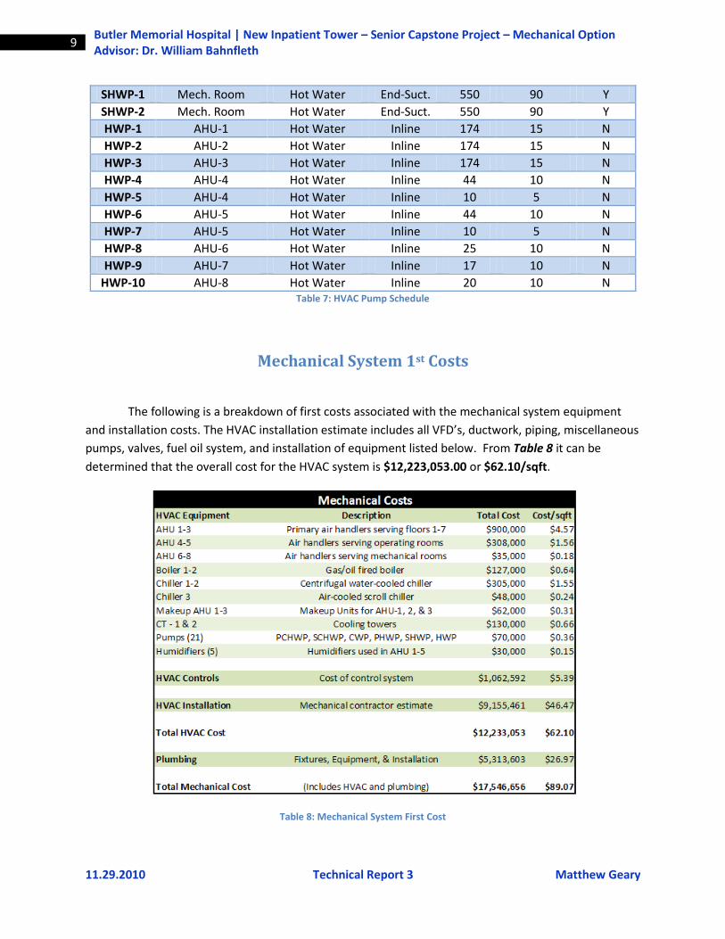
SHWP-1 Mech. Room Hot Water End-Suct. 550 90 Y
SHWP-2 Mech. Room Hot Water End-Suct. 550 90 Y
HWP-1 AHU-1 Hot Water Inline 174 15 N
HWP-2 AHU-2 Hot Water Inline 174 15 N
HWP-3 AHU-3 Hot Water Inline 174 15 N
HWP-4 AHU-4 Hot Water Inline 44 10 N
HWP-5 AHU-4 Hot Water Inline 10 5 N
HWP-6 AHU-5 Hot Water Inline 44 10 N
HWP-7 AHU-5 Hot Water Inline 10 5 N
HWP-8 AHU-6 Hot Water Inline 25 10 N
HWP-9 AHU-7 Hot Water Inline 17 10 N
HWP-10 AHU-8 Hot Water Inline 20 10 N Table 7: HVAC Pump Schedule
Mechanical System 1st Costs
The following is a breakdown of first costs associated with the mechanical system equipment
and installation costs. The HVAC installation estimate includes all VFD’s, ductwork, piping, miscellaneous
pumps, valves, fuel oil system, and installation of equipment listed below. From Table 8 it can be
determined that the overall cost for the HVAC system is $12,223,053.00 or $62.10/sqft.
Table 8: Mechanical System First Cost
11.29.2010 Technical Report 3 Matthew Geary
10 Butler Memorial Hospital | New Inpatient Tower – Senior Capstone Project – Mechanical Option Advisor: Dr. William Bahnfleth
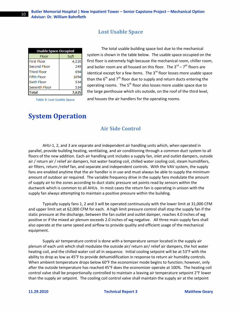
Lost Usable Space
The total usable building space lost due to the mechanical
system is shown in the table below. The usable space occupied on the
first floor is extremely high because the mechanical room, chiller room,
and boiler room are all housed on this floor. The 3rd – 7th floors are
identical except for a few items. The 3rd floor losses more usable space
than the 6th and 7th floor due to supply and return ducts entering the
operating rooms. The 5th floor also losses more usable space due to
the large penthouse which sits outside, on the roof of the third level,
and houses the air handlers for the operating rooms.
System Operation
Air Side Control
AHU-1, 2, and 3 are separate and independent air handling units which, when operated in parallel, provide building heating, ventilating, and air conditioning through a common duct system to all floors of the new addition. Each air handling unit includes a supply fan, inlet and outlet dampers, outside air / return air / relief air dampers, hot water heating coil, chilled water cooling coil, steam humidifiers, air filters, return /relief fan, and separate and independent controls. With the VAV system, the supply fans are enabled anytime that the air handler is in use and must always be able to supply the minimum amount of outdoor air required. The variable frequency drive in the supply fans modulate the amount of supply air to the zones according to duct static pressure set points read by sensors within the ductwork which is common to all AHUs. In most cases the return fan is operating in unison with the supply fan always attempting to maintain a positive pressure within the building. Typically supply fans 1, 2 and 3 will be operated continuously with the lower limit at 31,000 CFM and upper limit set at 62,000 CFM for each. A high limit pressure control shall stop the supply fan if the static pressure at the discharge, between the fan outlet and outlet damper, reaches 4.0 inches of wg positive or if the mixed air plenum exceeds 2.0 inches of wg negative. All three main supply fans shall also operate at the same speed and airflow to provide quality and efficient usage of the mechanical equipment. Supply air temperature control is done with a temperature sensor located in the supply air plenum of each unit which shall modulate the outside air/ return air/ relief air dampers, the hot water heating coil, and the chilled water coil all in sequence. Initial cooling setpoint will be at 53°F with the ability to drop as low as 45°F to provide dehumidification in response to return air humidity controls. When ambient temperature drops below 60°F the economizer mode begins to function; however, only after the outside temperature has reached 45°F does the economizer operate at 100%. The heating coil control valve shall be proportionally controlled to maintain a leaving air temperature setpoint 2°F lower than the supply air setpoint. The cooling coil control valve shall maintain the supply air at the setpoint
Table 9: Lost Usable Space
11.29.2010 Technical Report 3 Matthew Geary
11 Butler Memorial Hospital | New Inpatient Tower – Senior Capstone Project – Mechanical Option Advisor: Dr. William Bahnfleth
specified. In the case of winter heating, a steam humidifier in the supply air will be controlled by a relative humidity sensor in the return air in an effort to keep the relative humidity in the space at a minimum of 30%. Reheat coils at the zone have the ability to alter the temperature of the air, prior to the supply air entering the zone. Air handler units 4 and 5, which supply the operating rooms, function under almost identical conditions as AHU-1, 2, and 3 with the following exceptions: Each supply fan can only supply a maximum of 18,500 CFM and minimum of 14,610 CFM with a minimum outside air setpoint of 2,925 CFM if both fans are on or 3,700 CFM if only one fan is operating. The supply air temperature setpoint will be modulated between 40°F and 60°F in an effort to keep the zone temperature at exactly 60°F. It should be noted that the supply air temperature control can be overridden by dehumidification controls if necessary.
Water Side Chilled Water System
The primary chilled water system includes (2) centrifugal water chillers, (2) primary chiller circulating pumps, (2) distribution chilled water system pumps, and controls. The chilled water system shall be controlled automatically through a local direct digital control panel, packaged chiller controls, and pump variable speed drives using PI and PID control methods.
The packaged chiller controls shall cycle and modulate the chiller compressor to maintain the
chilled water supply temperature at 42°F. It should be noted that if the supply fan is stopped, flow through that cooling coil will also be eliminated. After the chiller is enabled, the control panel will send a signal to start the condenser water and chilled water pumps. At once there is proof of flow in the condenser and chilled water piping, the chillers will operate under their own control system.
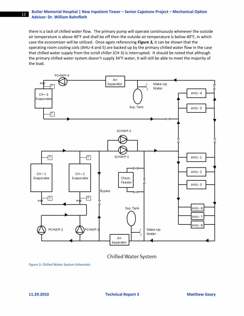
Referencing Figure 3 below, the primary chilled water pumps are in parallel and pump a
constant volume of water through the chillers. Because the pumps are in parallel, they provide inherent redundancy. Once the primary flow enters the chiller, secondary variable speed drive chilled water pumps, also in parallel, distribute the necessary quantity of chilled water to the loads. The secondary pumps are VSD so that they can match the load required at the zone. A differential pressure sensor in the chilled water supply and return will control the speed on the secondary pumps to maintain the appropriate setpoint. If the load does not call for 100% of the primary flow, a fraction of the primary flow gets returned to the chiller via the bypass. The first chiller is enabled when outside air temperature is 44°F or higher. If only one chiller is being used, the second chiller will come on-line if flow through the bypass is reversed for longer than 15 minutes, indicating a shortage of capacity. This is done using a flow sensor. If both chillers are running, the second chiller will come off line when the excess primary flow is equal to the flow through the second chiller for longer than 15 minutes, indicating a surplus of capacity. The first chiller is disabled when outside air temperature is below 43°F. After the chilled water is pumped through the secondary pumps and the load, it is circulated back to the return where the primary pumps begin the cycle again.
The operating room chilled water system is independent of the primary chilled water system
and consist of (1) 119 ton air-cooled scroll chiller, (1) circulating pump, and controls. The chiller controls will modulate chiller operation in order to maintain the desired chilled water leaving temperature setpoint of 34°F. A proof of flow sensor in the primary loop will prevent the chiller from operating if
11.29.2010 Technical Report 3 Matthew Geary
12 Butler Memorial Hospital | New Inpatient Tower – Senior Capstone Project – Mechanical Option Advisor: Dr. William Bahnfleth
there is a lack of chilled water flow. The primary pump will operate continuously whenever the outside air temperature is above 40°F and shall be off then the outside air temperature is below 40°F, in which case the economizer will be utilized. Once again referencing Figure 3, it can be shown that the operating room cooling coils (AHU-4 and 5) are backed up by the primary chilled water flow in the case that chilled water supply from the scroll chiller (CH-3) is interrupted. It should be noted that although the primary chilled water system doesn’t supply 34°F water, it will still be able to meet the majority of the load.
Figure 3: Chilled Water System Schematic
11.29.2010 Technical Report 3 Matthew Geary
13 Butler Memorial Hospital | New Inpatient Tower – Senior Capstone Project – Mechanical Option Advisor: Dr. William Bahnfleth
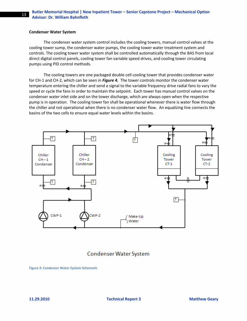
Condenser Water System
The condenser water system control includes the cooling towers, manual control valves at the cooling tower sump, the condenser water pumps, the cooling tower water treatment system and controls. The cooling tower water system shall be controlled automatically through the BAS from local direct digital control panels, cooling tower fan variable speed drives, and cooling tower circulating pumps using PID control methods. The cooling towers are one packaged double cell cooling tower that provides condenser water for CH-1 and CH-2, which can be seen in Figure 4. The tower controls monitor the condenser water temperature entering the chiller and send a signal to the variable frequency drive radial fans to vary the speed or cycle the fans in order to maintain the setpoint. Each tower has manual control valves on the condenser water inlet side and on the tower discharge, which are always open when the respective pump is in operation. The cooling tower fan shall be operational whenever there is water flow through the chiller and not operational when there is no condenser water flow. An equalizing line connects the basins of the two cells to ensure equal water levels within the basins.
Figure 4: Condenser Water System Schematic
11.29.2010 Technical Report 3 Matthew Geary
14 Butler Memorial Hospital | New Inpatient Tower – Senior Capstone Project – Mechanical Option Advisor: Dr. William Bahnfleth
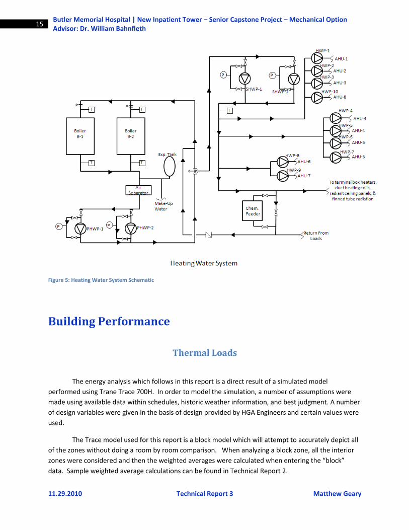
Heating Water System
The integral boiler controls modulate burners, stage lead-lag boilers, or stage burner level to maintain primary heating water loop temperature set point of 195 degrees F. Primary heating water pumps circulate hot water around the primary loop, as referenced in Figure 5. Primary heating water pump PHWP-1 runs whenever Boiler B-1 runs and will be off when B-1 is off. Pump PHWP-2 will run whenever Boiler B-2 runs and will be off when B-2 is off. The boiler isolation valve shall open whenever the related boiler runs, and shall close whenever the related boiler is off.
The secondary heating water pumps provide heating water distribution from the Boiler Room to
the building heating systems. The pumps have variable speed motor drives to provide variable heating water flow based on system heating load. A selected differential pressure sensor with its sensing elements in the heating water supply and return piping shall provide a signal to maintain the differential pressure at the setpoint by varying the pump(s) rotational speed, and by cycling the pump(s) on and off. The control setpoint at the sensor shall be the minimum differential pressure necessary to operate the most remote heating water coil or terminal unit. Actual setpoint shall be field determined, but the initial setpoint shall be 5 psig (between heating water supply and return piping).
When one operating pump is at 100% speed and the differential pressure setpoint cannot be
satisfied, start the next pump. Ramp up the additional pump until the two pumps operate at equal speeds. When two pumps are operating at 30% speed, one pump shall be shut down. On every start the heating pumps will be alternated so that the pump with the least run time becomes the lead. The secondary heating water system modulates a three-way control valve to maintain secondary loop heating-water supply temperature. The heating-water supply temperature should be reset according to outside temperature with a straight line relationship for the following conditions: 180°F heating water when outside temperature is minus 10°F or lower and 140°F heating water when outside temperature is 75 degrees F or warmer. After the water enters the secondary loop, it is distributed to the loads via the secondary hot water pumps, which operate in parallel. Inline hot water pumps are also integrated into the system and can be found at each heating coil. Other than heating coils, the secondary hot water loop also provides terminal boxes, duct heaters, radiant ceiling panels, and finned tube coils with hot water. Please refer to Figure 5 on the following page for a schematic diagram of the heating water system.
11.29.2010 Technical Report 3 Matthew Geary
15 Butler Memorial Hospital | New Inpatient Tower – Senior Capstone Project – Mechanical Option Advisor: Dr. William Bahnfleth
Figure 5: Heating Water System Schematic
Building Performance
Thermal Loads
The energy analysis which follows in this report is a direct result of a simulated model
performed using Trane Trace 700H. In order to model the simulation, a number of assumptions were
made using available data within schedules, historic weather information, and best judgment. A number
of design variables were given in the basis of design provided by HGA Engineers and certain values were
used.
The Trace model used for this report is a block model which will attempt to accurately depict all
of the zones without doing a room by room comparison. When analyzing a block zone, all the interior
zones were considered and then the weighted averages were calculated when entering the “block”
data. Sample weighted average calculations can be found in Technical Report 2.
11.29.2010 Technical Report 3 Matthew Geary
16 Butler Memorial Hospital | New Inpatient Tower – Senior Capstone Project – Mechanical Option Advisor: Dr. William Bahnfleth
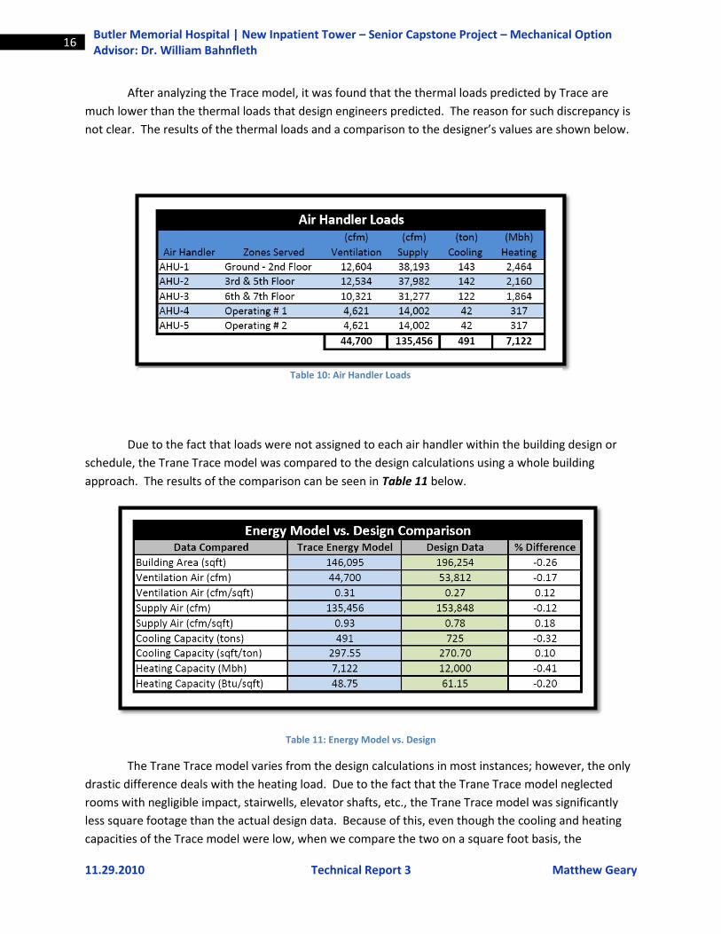
After analyzing the Trace model, it was found that the thermal loads predicted by Trace are
much lower than the thermal loads that design engineers predicted. The reason for such discrepancy is
not clear. The results of the thermal loads and a comparison to the designer’s values are shown below.
Due to the fact that loads were not assigned to each air handler within the building design or
schedule, the Trane Trace model was compared to the design calculations using a whole building
approach. The results of the comparison can be seen in Table 11 below.
Table 11: Energy Model vs. Design
The Trane Trace model varies from the design calculations in most instances; however, the only
drastic difference deals with the heating load. Due to the fact that the Trane Trace model neglected
rooms with negligible impact, stairwells, elevator shafts, etc., the Trane Trace model was significantly
less square footage than the actual design data. Because of this, even though the cooling and heating
capacities of the Trace model were low, when we compare the two on a square foot basis, the
Table 10: Air Handler Loads
11.29.2010 Technical Report 3 Matthew Geary
17 Butler Memorial Hospital | New Inpatient Tower – Senior Capstone Project – Mechanical Option Advisor: Dr. William Bahnfleth
differences are not as noticeable. The heating value of the Trace model was calculated at 7,122 Mbh at
peak load, compared to designed value of 12,000 Mbh at peak load. The reason for the drastic
differences in peak load is not clear. After many approaches were made to determine the discrepancy,
it is understood that the designers assumed that the peak heating load would occur with 100% outdoor
air supplying the rooms. This is not the case within the building, due to the VAV system only requiring,
at most, 33% outside air. Why the designer’s model was done in such manner is not clear.
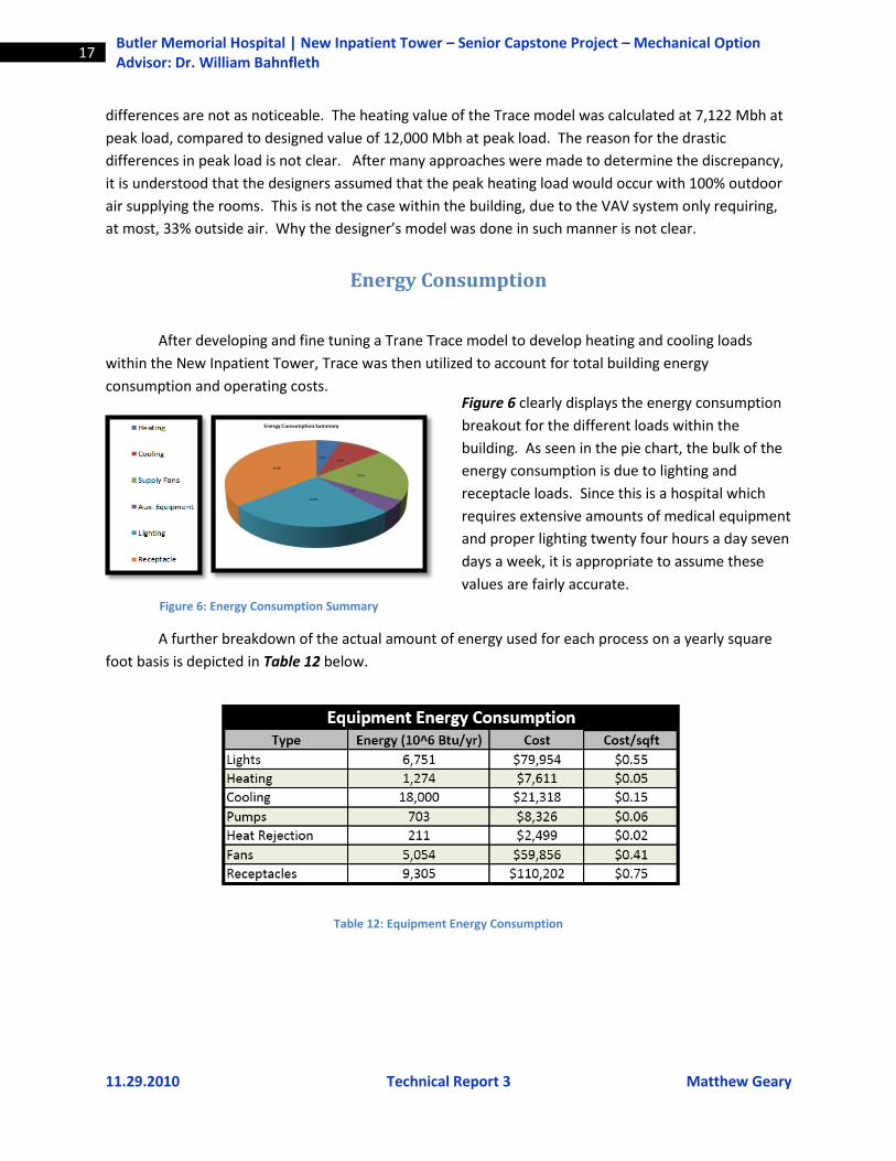
Energy Consumption
After developing and fine tuning a Trane Trace model to develop heating and cooling loads
within the New Inpatient Tower, Trace was then utilized to account for total building energy
consumption and operating costs.
Figure 6: Energy Consumption Summary
A further breakdown of the actual amount of energy used for each process on a yearly square
foot basis is depicted in Table 12 below.
Table 12: Equipment Energy Consumption
Figure 6 clearly displays the energy consumption
breakout for the different loads within the
building. As seen in the pie chart, the bulk of the
energy consumption is due to lighting and
receptacle loads. Since this is a hospital which
requires extensive amounts of medical equipment
and proper lighting twenty four hours a day seven
days a week, it is appropriate to assume these
values are fairly accurate.

11.29.2010 Technical Report 3 Matthew Geary
18 Butler Memorial Hospital | New Inpatient Tower – Senior Capstone Project – Mechanical Option Advisor: Dr. William Bahnfleth
Table 13: Energy Costs
It should be noted that although generic values for the cost of electricity and natural gas were
used in the Trane Trace energy model to calculate energy costs in Table 13, further research regarding
utility rates in the area have lead to more accurate results. The findings of more research have been
presented below in Table 14 and better reflect actual utility rates in the Butler, Pennsylvania area. The
utility company rates used in Table 14 reflects those of Allegheny Power and Columbia Gas, both of
which are large utility providers in the Butler, PA area. Figure 7 depicts overall monthly energy use.
Table 14: Utility Rates
Figure 7: Monthly Energy Consumption
11.29.2010 Technical Report 3 Matthew Geary
19 Butler Memorial Hospital | New Inpatient Tower – Senior Capstone Project – Mechanical Option Advisor: Dr. William Bahnfleth
An energy analysis was not done on the New Inpatient Tower when the building was designed.
The reason that an energy analysis was not done is due to the fact that the addition is not a LEED
certified building, and to perform an energy analysis adds extra costs which the owners and engineers
did not desire to support. The owners were also unwilling to supply information regarding utility bills.
For these reasons, there is not any way to compare the Trane Trace model results with actual energy
consumption.
LEED-NC Analysis
Information on the LEED-NC evaluation for the New Inpatient Tower’s mechanical system has not been available for this report. However, information from the design documents was available and provided a general idea of what LEED points were attained. The following LEED credits, that are associated with mechanical systems, are specified or referred to in the design documents and are believed to be worthy of credits. Other LEED points could be attained for the project; however, they are not listed due to their negligible association with the mechanical system.
Energy and Atmosphere
EA Prerequisite 1: Fundamental Commissioning of Building Energy Systems Required
Verify that the project’s energy-related systems are installed, and calibrated to perform according to the owner’s project requirements, basis of design and construction documents.
EA Prerequisite 2: Minimum Energy Performance Establish the minimum level of energy efficiency for the proposed building and systems to reduce environmental and economic impacts associated with excessive energy use. EA Prerequisite 3: Fundamental Refrigerant Management Reduce stratospheric ozone depletion by using zero use of chlorofluorocarbon (CFC)-based refrigerants in new base building heating, ventilating, air conditioning and refrigeration (HVAC&R) systems. EA Credit 4: Enhanced Refrigerant Management (2 points) Reduce ozone depletion and support early compliance with the Montreal Protocol while minimizing direct
contributions to climate change by selecting refrigerants and heating, ventilation, air conditioning and refrigeration (HVAC&R) equipment that minimize or eliminate the emission of compounds that contribute to ozone depletion and climate change.
11.29.2010 Technical Report 3 Matthew Geary
20 Butler Memorial Hospital | New Inpatient Tower – Senior Capstone Project – Mechanical Option Advisor: Dr. William Bahnfleth
Indoor Environmental Quality
IE Q Prerequisite 1: Minimum Indoor Air Quality Performance Establish minimum indoor air quality (IAQ) performance to enhance indoor air quality in buildings, thus contributing to the comfort and well-being of the occupants by meeting the minimum requirements of Sections 4 through 7 of ASHRAE Standard 62.1-2007, Ventilation for Acceptable Indoor Air Quality (with errata but without addenda1) and mechanical ventilation systems must be designed using the ventilation rate procedure or the applicable local code, whichever is more stringent. IE Q Prerequisite 2: Environmental Tobacco Smoke (ET S) Control Prevent or minimize exposure of building occupants, indoor surfaces and ventilation air distribution systems to environmental tobacco smoke (ETS) by prohibiting smoking in the building and prohibiting on-property smoking within 25 feet of entries, outdoor air intakes and operable windows. Provide signage to allow smoking in designated areas, prohibit smoking in designated areas or prohibit smoking on the entire property. IE Q Credit 1: Outdoor Air Delivery Monitoring (1 Point) Provide capacity for ventilation system monitoring to help promote occupant comfort and well-being by installing permanent monitoring systems to ensure that ventilation systems maintain design minimum requirements. IE Q Credit 2: Increased Ventilation (1 Point) Provide additional outdoor air ventilation to improve indoor air quality (IAQ) and promote occupant comfort, well-being and productivity by increasing breathing zone outdoor air ventilation rates to all occupied spaces by at least 30% above the minimum rates required by ASHRAE Standard 62.1-2007 (with errata but without addenda1) as determined by IEQ Prerequisite 1: Minimum Indoor Air Quality Performance. IE Q Credit 3.1: Construction Indoor Air Quality Management Plan (1 Point) Reduce indoor air quality (IAQ) problems resulting from construction or renovation and promote the comfort and well-being of construction workers and building occupants. Develop and implement an IAQ management plan for the construction and preoccupancy phases of the building as follows:
During construction, meet or exceed the recommended control measures of the Sheet Metal and Air Conditioning National Contractors Association (SMACNA) IAQ Guidelines.
Protect stored on-site and installed absorptive materials from moisture damage.
If permanently installed air handlers are used during construction, filtration media with a minimum efficiency reporting value (MERV) of 8 must be used at each return air grille, as determined by ASHRAE Standard 52.2-1999 (with errata but without addenda1). Replace all filtration media immediately prior to occupancy.
11.29.2010 Technical Report 3 Matthew Geary
21 Butler Memorial Hospital | New Inpatient Tower – Senior Capstone Project – Mechanical Option Advisor: Dr. William Bahnfleth
IE Q Credit 3.2: Construction Indoor Air Quality Management Plan—Before Occupancy (1 Point) Reduce indoor air quality (IAQ) problems resulting from construction or renovation to promote the comfort and well-being of construction workers and building occupants. Develop an IAQ management plan and implement it after all finishes have been installed and the building has been completely cleaned before occupancy. After construction ends, prior to occupancy and with all interior finishes installed, install new filtration media and, perform a building flush-out by supplying a total air volume of 14,000 cubic feet of outdoor air per square foot of floor area while maintaining an internal temperature of at least 60° F and relative humidity no higher than 60%. IE Q Credit 6.2: Controllability of Systems—Thermal Comfort (1 Point) Provide a high level of thermal comfort system control1 by individual occupants or groups in multi-occupant spaces (e.g., classrooms or conference areas) and promote their productivity, comfort and well-being by providing individual comfort controls for 50% (minimum) of the building occupants to enable adjustments to meet individual needs and preferences. Provide comfort system controls for all shared multi-occupant spaces to enable adjustments that meet group needs and preferences. Conditions for thermal comfort are described in ASHRAE Standard 55-2004 and include the primary factors of air temperature, radiant temperature, air speed and humidity. IE Q Credit 7.1: Thermal Comfort—Design (1 Point) Provide a comfortable thermal environment that promotes occupant productivity and well-being by designing heating, ventilating and air conditioning (HVAC) systems and the building envelope to meet the requirements of ASHRAE Standard 55-2004, Thermal Comfort Conditions for Human Occupancy and demonstrate design compliance in accordance with the Section 6.1.1 documentation. All of the previous credits area assumed to be attainable by the design of New Inpatient Tower. The mechanical system was able to earn 8 points out of a possible 44 points that deal with the mechanical systems. The system could most likely earn more credits if an energy analysis was performed on the building by engineers.
Overall Evaluation Summary
The overall concept of variable air volume has been utilized and accepted for many years with
large amounts of success. In this particular application the VAV system was chosen because of its
reliability, redundancy, and past success in health care facilities around the world. Variable air volume
also has the advantages of a relatively low first cost, low maintenance, and decent efficiency. The first
cost of the HVAC was roughly $12,000,000. According to an energy model performed by Trane Trace
the mechanical system costs roughly $100,000 per year to operate, which is approximately $0.69/sqft.
The proposed lifetime for the boilers, chillers, and air handlers under proper maintenance is 30
years. Maintenance for a variable air volume system should be a minimal expense. Some areas that will
11.29.2010 Technical Report 3 Matthew Geary
22 Butler Memorial Hospital | New Inpatient Tower – Senior Capstone Project – Mechanical Option Advisor: Dr. William Bahnfleth
need routine maintenance are filter replacement, sensor re-calibration, cleaning of air handling
equipment and coils, maintaining condenser, chilled, and heating water quality, as well as unforeseen
maintenance such as a fan or pump burning up, or a leaky valve needing replaced.
One downfall of the variable air volume system is the extensive amount of ductwork that must
be installed and the loss of usable floor space. The main supply and return shafts occupy a large portion
of the usable space within the tower. This space could be used for more patient rooms or additional
support space if a hydronic system was used in lieu of variable air volume. Utilizing a hydronic system
would allow for smaller ductwork and more usable space within the hospital.
Another drawback of the variable air volume is related to the reheat coils within the terminal
units. The idea of cooling air to meet the largest load, and then reheating the air for smaller cooling
loads defies all logic when it comes to designing an economic system. The energy used by the boiler to
create hot water for the reheat coils within the terminal boxes is wasteful.
Variable air volume systems can also pose problems with regards to meeting the minimum
requirements of outside air. If the system is installed or operated incorrectly, there is a chance that at
low airflows, the minimum amount of outside air may not be met. If this occurs, ventilation rates will
not be met and the indoor air quality of the hospital will diminish.
Looking forward, the hospital appears to be a prime candidate for a 100% outside air system
with hydronic heating and cooling. The tower would benefit from the constant supply of fresh outside
air as well as reduced heat and cooling capacities in the chillers and boilers. With the current design, the
hospital exhausts a large amount of air, which at this point is simply discharged into the atmosphere.
Installing a dedicated outdoor air system with a heat recovery wheel on the exhaust air would also
integrate very well with a hydronic system using 100% outside air.

11.29.2010 Technical Report 3 Matthew Geary
23 Butler Memorial Hospital | New Inpatient Tower – Senior Capstone Project – Mechanical Option Advisor: Dr. William Bahnfleth
APPENDIX A
List of Tables and Figures
11.29.2010 Technical Report 3 Matthew Geary
24 Butler Memorial Hospital | New Inpatient Tower – Senior Capstone Project – Mechanical Option Advisor: Dr. William Bahnfleth
List of Tables Table 1-Air Handler Summary ....................................................................................................................... 7
Table 2: Air Handler Fan Schedule ................................................................................................................ 7
Table 3: Exhaust Fan Schedule ...................................................................................................................... 8
Table 4: Chiller Schedule ............................................................................................................................... 8
Table 5: Boiler Schedule ................................................................................................................................ 8
Table 6: Cooling Tower Schedule .................................................................................................................. 8
Table 7: HVAC Pump Schedule ...................................................................................................................... 9
Table 8: Mechanical System First Cost .......................................................................................................... 9
Table 9: Lost Usable Space .......................................................................................................................... 10
Table 11: Energy Model vs. Design ............................................................................................................. 16
Table 10: Air Handler Loads ........................................................................................................................ 16
Table 12: Equipment Energy Consumption ................................................................................................ 17
Table 13: Energy Costs ................................................................................................................................ 18
Table 14: Utility Rates ................................................................................................................................. 18
List of Figures Figure 1: Outdoor Design Conditions ............................................................................................................ 5
Figure 2: Indoor Design Conditions ............................................................................................................... 6
Figure 3: Chilled Water System Schematic ................................................................................................. 12
Figure 4: Condenser Water System Schematic ........................................................................................... 13
Figure 5: Heating Water System Schematic ................................................................................................ 15
Figure 6: Energy Consumption Summary ................................................................................................... 17
Figure 7: Monthly Energy Consumption ..................................................................................................... 18


![Technical Report 1 - engr.psu.edu...September 16, 2013 [TECHNICAL REPORT 1] Kevin R. Kroener | Executive Summary 1 Executive Summary The Wardman West Residential project or The Woodley](https://img.pdfslide.net/doc/110x75/5e9d8820344d57436c71d70b/technical-report-1-engrpsuedu-september-16-2013-technical-report-1-kevin.jpg)