Embed Size (px)
Citation preview
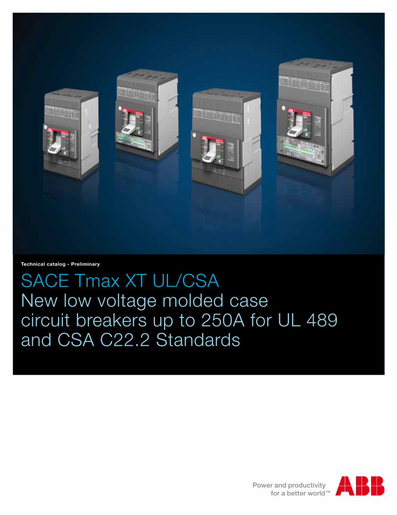
SACE Tmax XT UL/CSANew low voltage molded case circuit breakers up to 250A for UL 489 and CSA C22.2 Standards
Technical catalog - Preliminary

ABB catalog | 1SDC210059D0201
11
5
3
7
2
6
4
8
Index
Construction characteristics
The SACE Tmax XT ranges
Accessories
Characteristic curves and technical information
Overall dimensions
Wiring diagrams
Ordering codes
Glossary

2
New SACE Tmax XT.Simply XTraordinary.
ABB SACE is proud to present the result of a long and intense research and development project: the new SACE Tmax XT up to 250A - ABB SACE’s new family of molded case circuit breakers.

3
Today a highly advanced range of circuit breakers has been introduced, with unparalleled versatility of use and the ability to solve all installation problems brilliantly. You can find the new SACE Tmax XT in three-pole and four-pole, fixed, plug-in and withdrawable versions. They are fitted with the very latest generation thermomagnetic and electronic trip units, with the possibility of interchangeability. The new SACE Tmax XT sets a new technological standard and
provides the freedom to build installations with extraordinary performances. An extraordinary demonstration of ABB SACE’s innovation capability. Extraordinary latest generation electronics. Extraordinary coverage of all plant requirements. Extraordinary performances in compact dimensions.Extraordinary simplicity of installation and putting into service. Extraordinary range of accessories available.
New SACE Tmax XT. Simply XTraordinary.

4
New SACE Tmax XT.XTraordinary completeness of range.
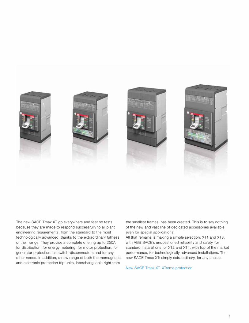
There are the 4 new SACE Tmax XT UL/CSA frames:– small XT1 up to 125A – high-performing XT2 up to 125A – reliable XT3 up to 225A – powerful XT4 up to 250A
5
The new SACE Tmax XT go everywhere and fear no tests because they are made to respond successfully to all plant engineering requirements, from the standard to the most technologically advanced, thanks to the extraordinary fullness of their range. They provide a complete offering up to 250A for distribution, for energy metering, for motor protection, for generator protection, as switch-disconnectors and for any other needs. In addition, a new range of both thermomagnetic and electronic protection trip units, interchangeable right from
the smallest frames, has been created. This is to say nothing of the new and vast line of dedicated accessories available, even for special applications.All that remains is making a simple selection: XT1 and XT3, with ABB SACE’s unquestioned reliability and safety, for standard installations, or XT2 and XT4, with top of the market performance, for technologically advanced installations. The new SACE Tmax XT: simply extraordinary, for any choice.
New SACE Tmax XT. XTreme protection.

6
New SACE Tmax XT.XTraordinary advanced electronics.
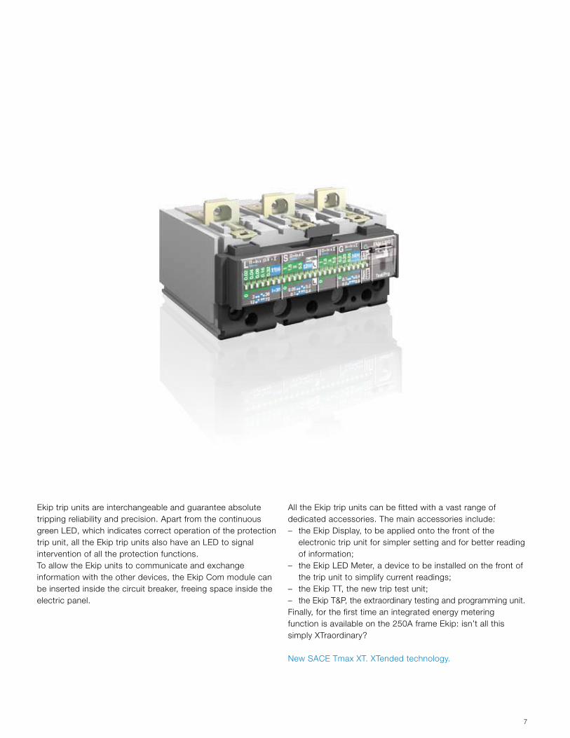
Welcome a totally renewed, high-performing and versatile range of electronic trip units.Ekip: the new, very latest generation electronic trip units which equip the new frames of SACE Tmax XT2 and SACE Tmax XT4 circuit breakers.
7
Ekip trip units are interchangeable and guarantee absolute tripping reliability and precision. Apart from the continuous green LED, which indicates correct operation of the protection trip unit, all the Ekip trip units also have an LED to signal intervention of all the protection functions. To allow the Ekip units to communicate and exchange information with the other devices, the Ekip Com module can be inserted inside the circuit breaker, freeing space inside the electric panel.
All the Ekip trip units can be fitted with a vast range of dedicated accessories. The main accessories include: – the Ekip Display, to be applied onto the front of the
electronic trip unit for simpler setting and for better reading of information;
– the Ekip LED Meter, a device to be installed on the front of the trip unit to simplify current readings;
– the Ekip TT, the new trip test unit; – the Ekip T&P, the extraordinary testing and programming unit. Finally, for the first time an integrated energy metering function is available on the 250A frame Ekip: isn’t all this simply XTraordinary?
New SACE Tmax XT. XTended technology.

11
ABB catalog | 1SDC210059D0201 1/1
Construction characteristics 1/2
Regulations and reference standards 1/5
Identification of the SACE Tmax XT circuit breakers 1/6
Nomenclature of the trip units 1/7
Construction characteristics
1
1/2 1SDC210059D0201 | ABB catalog
Construction characteristics
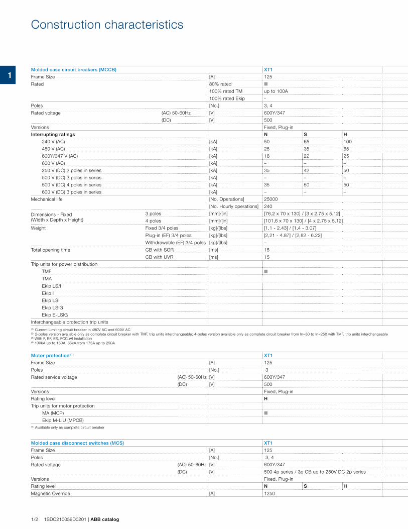
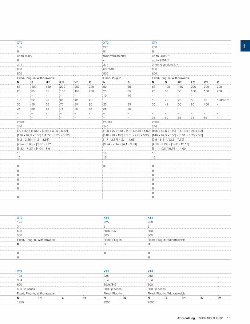
Molded case circuit breakers (MCCB) XT1 XT2 XT3 XT4
Frame Size [A] 125 125 225 250
Rated 80% rated ■ ■ ■ ■
100% rated TM up to 100A up to 100A fixed version only up to 250A (3)
100% rated Ekip - ■ - up to 250A (3)
Poles [No.] 3, 4 3, 4 3, 4 2 (for N version) 3, 4
Rated voltage (AC) 50-60Hz [V] 600Y/347 600 600Y/347 600
(DC) [V] 500 500 500 600
Versions Fixed, Plug-in Fixed, Plug-in, Withdrawable Fixed, Plug-in Fixed, Plug-in, Withdrawable
Interrupting ratings N S H N S H(1) L(1) V(1) X N S N S H(1) L(1) V(1) X
240 V (AC) [kA] 50 65 100 65 100 150 200 200 200 50 65 65 100 150 200 200 200
480 V (AC) [kA] 25 35 65 25 35 65 100 150 200 25 35 25 35 65 100 150 200
600Y/347 V (AC) [kA] 18 22 25 – – – – – – 10 10 – – – – – –
600 V (AC) [kA] – – – 18 22 25 35 42 42 – – 18 22 25 50 65 100/65 (4)
250 V (DC) 2 poles in series [kA] 35 42 50 35 50 65 75 85 85 25 35 35 42 50 85 100 –
500 V (DC) 3 poles in series [kA] – – – 35 50 65 75 85 85 25 35 – – – – – –
500 V (DC) 4 poles in series [kA] 35 50 50 – – – – – – – – – – – – – –
600 V (DC) 3 poles in series [kA] – – – – – – – – – – – 35 50 65 75 85 –
Mechanical life [No. Operations] 25000 25000 25000 25000
[No. Hourly operations] 240 240 240 240
Dimensions - Fixed (Width x Depth x Height)
3 poles [mm]/[in] [76,2 x 70 x 130] / [3 x 2.75 x 5.12] [90 x 82,5 x 130] / [3.54 x 3.25 x 5.12] [105 x 70 x 150] / [4.13 x 2.75 x 5.90] [105 x 82,5 x 160] - [4.13 x 3.25 x 6.3]
4 poles [mm]/[in] [101,6 x 70 x 130] / [4 x 2.75 x 5.12] [120 x 82,5 x 130] / [4.72 x 3.25 x 5.12] [140 x 70 x 150] / [5.51 x 2.75 x 5.90] [140 x 82,5 x 160] - [5.51 x 3.25 x 6.3]
Weight Fixed 3/4 poles [kg]/[lbs] [1,1 - 2.43] / [1,4 - 3.07] [1,2 - 2.65] / [1,6 - 3.53] [1,7 - 3.37] / [2,1 - 4.63] [2,5 - 5.51] / [3,5 - 7.72]
Plug-in (EF) 3/4 poles [kg]/[lbs] [2,21 - 4.87] / [2,82 - 6.22] [2,54 - 5.60] / [3,27 - 7.21] [3,24 - 7.14] / [4,1 - 9.04] [4,19 - 9.24] / [5,52 - 12.17]
Withdrawable (EF) 3/4 poles [kg]/[lbs] – [3,32 - 7.32] / [4,04 - 8.91] [5 - 11.02] / [6,76 - 14.90]
Total opening time CB with SOR [ms] 15 15 15 15
CB with UVR [ms] 15 15 15 15
Trip units for power distribution
TMF ■ ■ ■ ■
TMA ■ ■
Ekip LS/I ■ ■
Ekip I ■ ■
Ekip LSI ■ ■
Ekip LSIG ■ ■
Ekip E-LSIG ■
Interchangeable protection trip units ■ ■
(1) Current Limiting circuit breaker in 480V AC and 600V AC(2) 2-poles version available only as complete circuit breaker with TMF, trip units interchangeable; 4-poles version available only as complete circuit breaker from In=80 to In=250 with TMF, trip units interchangeable(3) With F, EF, ES, FCCuAl installation (4) 100kA up to 150A, 65kA from 175A up to 250A
Motor protection (1) XT1 XT2 XT3 XT4
Frame Size [A] 125 125 225 250
Poles [No.] 3 3 3 3
Rated service voltage (AC) 50-60Hz [V] 600Y/347 600 600Y/347 600
(DC) [V] 500 500 500 600
Versions Fixed, Plug-in Fixed, Plug-in, Withdrawable Fixed, Plug-in Fixed, Plug-in, Withdrawable
Rating level H H S H
Trip units for motor protection
MA (MCP) ■ ■ ■ ■
Ekip M-LIU (MPCB) ■ ■
(1) Available only as complete circuit breaker
Molded case disconnect switches (MCS) XT1 XT2 XT3 XT4
Frame Size [A] 125 125 225 250
Poles [No.] 3, 4 3, 4 3, 4 3, 4
Rated voltage (AC) 50-60Hz [V] 600Y/347 600 600Y/347 600
(DC) [V] 500 4p series / 3p CB up to 250V DC 2p series 500 3p series 500 3p series 600 3p series
Versions Fixed, Plug-in Fixed, Plug-in, Withdrawable Fixed, Plug-in Fixed, Plug-in, Withdrawable
Rating level N S H N H L V N S N S H L V
Magnetic Override [A] 1250 1250 2250 2500
11
ABB catalog | 1SDC210059D0201 1/3
Molded case circuit breakers (MCCB) XT1 XT2 XT3 XT4
Frame Size [A] 125 125 225 250
Rated 80% rated ■ ■ ■ ■
100% rated TM up to 100A up to 100A fixed version only up to 250A (3)
100% rated Ekip - ■ - up to 250A (3)
Poles [No.] 3, 4 3, 4 3, 4 2 (for N version) 3, 4
Rated voltage (AC) 50-60Hz [V] 600Y/347 600 600Y/347 600
(DC) [V] 500 500 500 600
Versions Fixed, Plug-in Fixed, Plug-in, Withdrawable Fixed, Plug-in Fixed, Plug-in, Withdrawable
Interrupting ratings N S H N S H(1) L(1) V(1) X N S N S H(1) L(1) V(1) X
240 V (AC) [kA] 50 65 100 65 100 150 200 200 200 50 65 65 100 150 200 200 200
480 V (AC) [kA] 25 35 65 25 35 65 100 150 200 25 35 25 35 65 100 150 200
600Y/347 V (AC) [kA] 18 22 25 – – – – – – 10 10 – – – – – –
600 V (AC) [kA] – – – 18 22 25 35 42 42 – – 18 22 25 50 65 100/65 (4)
250 V (DC) 2 poles in series [kA] 35 42 50 35 50 65 75 85 85 25 35 35 42 50 85 100 –
500 V (DC) 3 poles in series [kA] – – – 35 50 65 75 85 85 25 35 – – – – – –
500 V (DC) 4 poles in series [kA] 35 50 50 – – – – – – – – – – – – – –
600 V (DC) 3 poles in series [kA] – – – – – – – – – – – 35 50 65 75 85 –
Mechanical life [No. Operations] 25000 25000 25000 25000
[No. Hourly operations] 240 240 240 240
Dimensions - Fixed (Width x Depth x Height)
3 poles [mm]/[in] [76,2 x 70 x 130] / [3 x 2.75 x 5.12] [90 x 82,5 x 130] / [3.54 x 3.25 x 5.12] [105 x 70 x 150] / [4.13 x 2.75 x 5.90] [105 x 82,5 x 160] - [4.13 x 3.25 x 6.3]
4 poles [mm]/[in] [101,6 x 70 x 130] / [4 x 2.75 x 5.12] [120 x 82,5 x 130] / [4.72 x 3.25 x 5.12] [140 x 70 x 150] / [5.51 x 2.75 x 5.90] [140 x 82,5 x 160] - [5.51 x 3.25 x 6.3]
Weight Fixed 3/4 poles [kg]/[lbs] [1,1 - 2.43] / [1,4 - 3.07] [1,2 - 2.65] / [1,6 - 3.53] [1,7 - 3.37] / [2,1 - 4.63] [2,5 - 5.51] / [3,5 - 7.72]
Plug-in (EF) 3/4 poles [kg]/[lbs] [2,21 - 4.87] / [2,82 - 6.22] [2,54 - 5.60] / [3,27 - 7.21] [3,24 - 7.14] / [4,1 - 9.04] [4,19 - 9.24] / [5,52 - 12.17]
Withdrawable (EF) 3/4 poles [kg]/[lbs] – [3,32 - 7.32] / [4,04 - 8.91] [5 - 11.02] / [6,76 - 14.90]
Total opening time CB with SOR [ms] 15 15 15 15
CB with UVR [ms] 15 15 15 15
Trip units for power distribution
TMF ■ ■ ■ ■
TMA ■ ■
Ekip LS/I ■ ■
Ekip I ■ ■
Ekip LSI ■ ■
Ekip LSIG ■ ■
Ekip E-LSIG ■
Interchangeable protection trip units ■ ■
(1) Current Limiting circuit breaker in 480V AC and 600V AC(2) 2-poles version available only as complete circuit breaker with TMF, trip units interchangeable; 4-poles version available only as complete circuit breaker from In=80 to In=250 with TMF, trip units interchangeable(3) With F, EF, ES, FCCuAl installation (4) 100kA up to 150A, 65kA from 175A up to 250A
Motor protection (1) XT1 XT2 XT3 XT4
Frame Size [A] 125 125 225 250
Poles [No.] 3 3 3 3
Rated service voltage (AC) 50-60Hz [V] 600Y/347 600 600Y/347 600
(DC) [V] 500 500 500 600
Versions Fixed, Plug-in Fixed, Plug-in, Withdrawable Fixed, Plug-in Fixed, Plug-in, Withdrawable
Rating level H H S H
Trip units for motor protection
MA (MCP) ■ ■ ■ ■
Ekip M-LIU (MPCB) ■ ■
(1) Available only as complete circuit breaker
Molded case disconnect switches (MCS) XT1 XT2 XT3 XT4
Frame Size [A] 125 125 225 250
Poles [No.] 3, 4 3, 4 3, 4 3, 4
Rated voltage (AC) 50-60Hz [V] 600Y/347 600 600Y/347 600
(DC) [V] 500 4p series / 3p CB up to 250V DC 2p series 500 3p series 500 3p series 600 3p series
Versions Fixed, Plug-in Fixed, Plug-in, Withdrawable Fixed, Plug-in Fixed, Plug-in, Withdrawable
Rating level N S H N H L V N S N S H L V
Magnetic Override [A] 1250 1250 2250 2500
1
1SD
C21
0A20
F000
1
1/4 1SDC210059D0201 | ABB catalog
Positive operation
Installation positions
Protection degrees
Test pushbutton
Construction characteristics
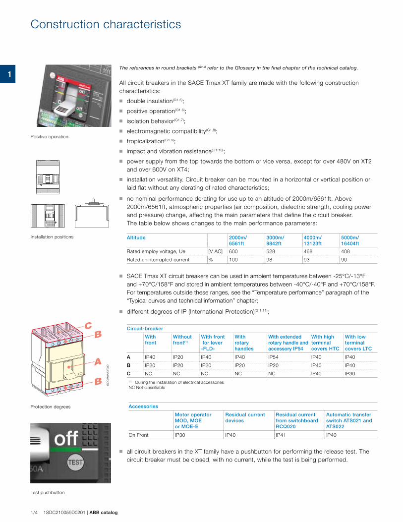
The references in round brackets (Gx.x) refer to the Glossary in the final chapter of the technical catalog.
All circuit breakers in the SACE Tmax XT family are made with the following construction characteristics:
■ double insulation(G1.5);
■ positive operation(G1.6);
■ isolation behavior(G1.7);
■ electromagnetic compatibility(G1.8);
■ tropicalization(G1.9);
■ impact and vibration resistance(G1.10);
■ power supply from the top towards the bottom or vice versa, except for over 480V on XT2 and over 600V on XT4;
■ installation versatility. Circuit breaker can be mounted in a horizontal or vertical position or laid flat without any derating of rated characteristics;
■ no nominal performance derating for use up to an altitude of 2000m/6561ft. Above 2000m/6561ft, atmospheric properties (air composition, dielectric strength, cooling power and pressure) change, affecting the main parameters that define the circuit breaker. The table below shows changes to the main performance parameters:
Altitude 2000m/6561ft
3000m/9842ft
4000m/13123ft
5000m/16404ft
Rated employ voltage, Ue [V AC] 600 528 468 408
Rated uninterrupted current % 100 98 93 90
■ SACE Tmax XT circuit breakers can be used in ambient temperatures between -25°C/-13°F and +70°C/158°F and stored in ambient temperatures between -40°C/-40°F and +70°C/158°F. For temperatures outside these ranges, see the “Temperature performance” paragraph of the “Typical curves and technical information” chapter;
■ different degrees of IP (International Protection)(G 1.11);
Circuit-breaker
With front
Without front(1)
With front for lever -FLD-
With rotary handles
With extended rotary handle and accessory IP54
With high terminal covers HTC
With low terminal covers LTC
A IP40 IP20 IP40 IP40 IP54 IP40 IP40
B IP20 IP20 IP20 IP20 IP20 IP40 IP40
C NC NC NC NC NC IP40 IP30(1) During the installation of electrical accessories NC Not classifiable
Accessories
Motor operatorMOD, MOE or MOE-E
Residual current devices
Residual current from switchboard RCQ020
Automatic transfer switch ATS021 and ATS022
On Front IP30 IP40 IP41 IP40
■ all circuit breakers in the XT family have a pushbutton for performing the release test. The circuit breaker must be closed, with no current, while the test is being performed.
11
ABB catalog | 1SDC210059D0201 1/5
Regulations and reference standards
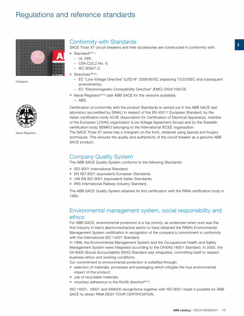
Conformity with Standards SACE Tmax XT circuit breakers and their accessories are constructed in conformity with:
■ Standard(G6.1):– UL 489;– CSA C22.2 No. 5;– IEC 60947-2;
■ Directives(G6.2):– EC “Low Voltage Directive” (LVD) N° 2006/95/EC (replacing 73/23/EEC and subsequent
amendments);– EC “Electromagnetic Compatibility Directive” (EMC) 2004/108/CE;
■ Naval Registers(G6.3) (ask ABB SACE for the versions available):– ABS.
Certification of conformity with the product Standards is carried out in the ABB SACE test laboratory (accredited by SINAL) in respect of the EN 45011 European Standard, by the Italian certification body ACAE (Association for Certification of Electrical Apparatus), member of the European LOVAG organization (Low Voltage Agreement Group) and by the Swedish certification body SEMKO belonging to the International IECEE organization.The SACE Tmax XT series has a hologram on the front, obtained using special anti-forgery techniques. This ensures the quality and authenticity of the circuit breaker as a genuine ABB SACE product.
Company Quality SystemThe ABB SACE Quality System conforms to the following Standards:
■ ISO 9001 International Standard;■ EN ISO 9001 (equivalent) European Standards;■ UNI EN ISO 9001 (equivalent) Italian Standards;■ IRIS International Railway Industry Standard.
The ABB SACE Quality System attained its first certification with the RINA certification body in 1990.
Environmental management system, social responsibility and ethicsFor ABB SACE, environmental protection is a top priority, as evidenced when ours was the first industry in Italy’s electromechanical sector to have obtained the RINA’s Environmental Management System certification in recognition of the company’s commitment in conformity with the International ISO 14001 Standard.In 1999, the Environmental Management System and the Occupational Health and Safety Management System were integrated according to the OHSAS 18001 Standard. In 2005, the SA 8000 (Social Accountability 8000) Standard was integrated, committing itself to respect business ethics and working conditions.Our commitment to environmental protection is solidified through:■ selection of materials, processes and packaging which mitigate the true environmental
impact of the product;■ use of recyclable materials; ■ voluntary adherence to the RoHS directive(G6.4).
ISO 14001, 18001 and SA8000 recognitions together with ISO 9001 made it possible for ABB SACE to obtain RINA BEST FOUR CERTIFICATION.
Naval Registers
Hologram
1
Ue=690V AC
415440690
Uimp=8kVUi=800V
IEC60947-2
220 10070
7070
6510
7550
7575
5050
250500
Ue (V) Icu (kA) Ics (%Icu)
f= 50-60 Hz
S/NXT1H 125
DC WIRING DIAGRAMS2 POLES 250VDC 4 POLES 251
TO 500VDCCAUTION: THE INSTALLATION OF
THE INSULATING BARRIERBETWEEN THE C.B AND THE BACK
PLATE SHOULD BE PROVIDEDWHEN THE C.B IS MOUNTED ON A
FLAT NON-INSULATED METALSURFACE
CAUTION:29X68X2.5 mm SPACING BARRIERS
PROVIDED WITH THE CIRCUITBREAKER MUST BE PLACED
BETWEEN UPPER AND LOWERPOLES OF THE CIRCUIT BREAKER
AND BETWEEN ADJACENT CIRCUITBREAKERS OF THE SAME TYPE
131
10
6
341
5
9
7
8
2
14
44
12
15 16
1110
1/6 1SDC210059D0201 | ABB catalog
Identification of the SACE Tmax XT circuit breakers
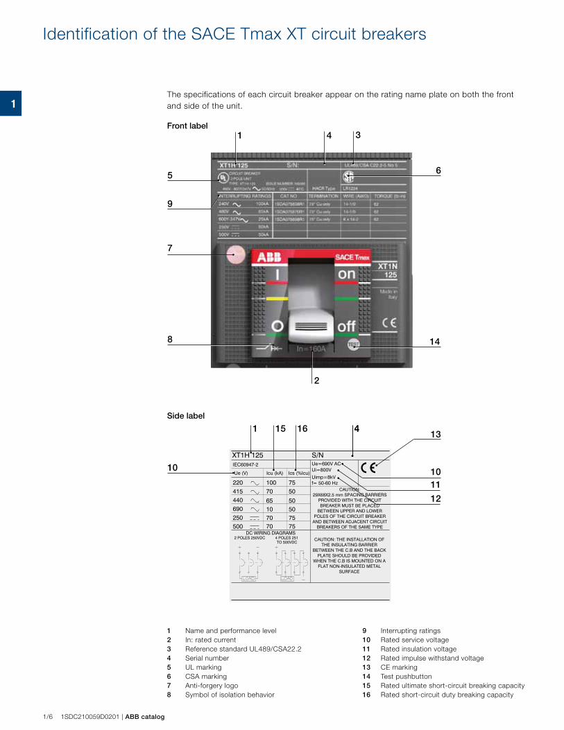
The specifications of each circuit breaker appear on the rating name plate on both the front and side of the unit.
Front label
1 Name and performance level2 In: rated current3 Reference standard UL489/CSA22.24 Serial number5 UL marking6 CSA marking7 Anti-forgery logo8 Symbol of isolation behavior
Side label
9 Interrupting ratings10 Rated service voltage11 Rated insulation voltage12 Rated impulse withstand voltage13 CE marking14 Test pushbutton15 Rated ultimate short-circuit breaking capacity16 Rated short-circuit duty breaking capacity
11
ABB catalog | 1SDC210059D0201 1/7
9 Interrupting ratings10 Rated service voltage11 Rated insulation voltage12 Rated impulse withstand voltage13 CE marking14 Test pushbutton15 Rated ultimate short-circuit breaking capacity16 Rated short-circuit duty breaking capacity
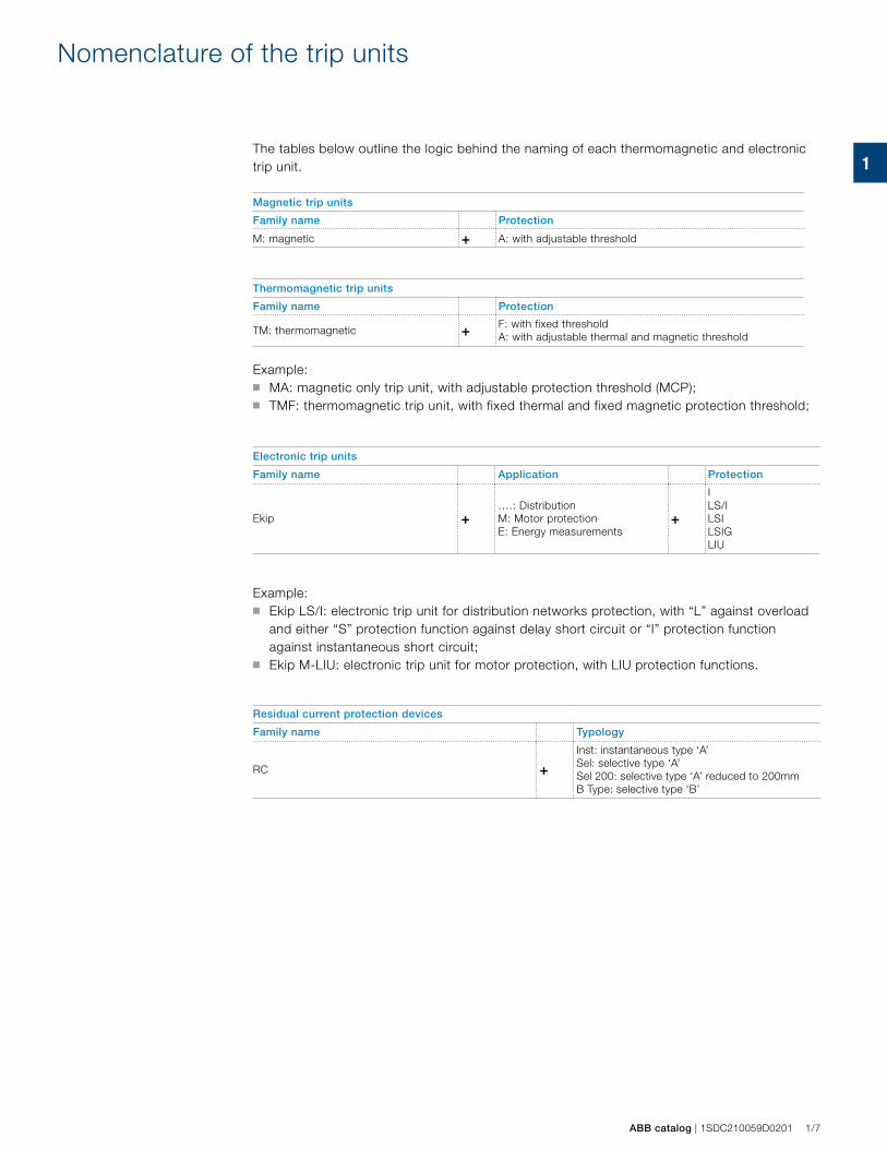
The tables below outline the logic behind the naming of each thermomagnetic and electronic trip unit.
Magnetic trip units
Family name Protection
M: magnetic + A: with adjustable threshold
Thermomagnetic trip units
Family name Protection
TM: thermomagnetic + F: with fixed thresholdA: with adjustable thermal and magnetic threshold
Example:■ MA: magnetic only trip unit, with adjustable protection threshold (MCP);■ TMF: thermomagnetic trip unit, with fixed thermal and fixed magnetic protection threshold;
Electronic trip units
Family name Application Protection
Ekip +….: DistributionM: Motor protectionE: Energy measurements
+
I LS/ILSILSIGLIU
Example: ■ Ekip LS/I: electronic trip unit for distribution networks protection, with “L” against overload
and either “S” protection function against delay short circuit or “I” protection function against instantaneous short circuit;
■ Ekip M-LIU: electronic trip unit for motor protection, with LIU protection functions.
Residual current protection devices
Family name Typology
RC +Inst: instantaneous type ‘A’Sel: selective type ‘A’ Sel 200: selective type ‘A’ reduced to 200mmB Type: selective type ‘B’
Nomenclature of the trip units

1
1/8 1SDC210059D0201 | ABB catalog
2
ABB catalogue | 1SDC210059D0201 2/1
The SACE Tmax XT ranges
The SACE Tmax XT family ranges 2/2
Circuit breakers for power distribution
Main characteristics 2/3
Thermomagnetic trip units 2/4
Electronic trip units 2/6
Circuit breakers for motor protection
Main characteristics 2/13
Magnetic trip units 2/14
Electronic trip units 2/15
Molded case switch disconnectors
Main characteristics 2/16
Current Limiting
Electrical characteristics 2/17
Special applications
Communication system 2/18
2
2/2 1SDC210059D0201 | ABB catalogue
The SACE Tmax XT family ranges
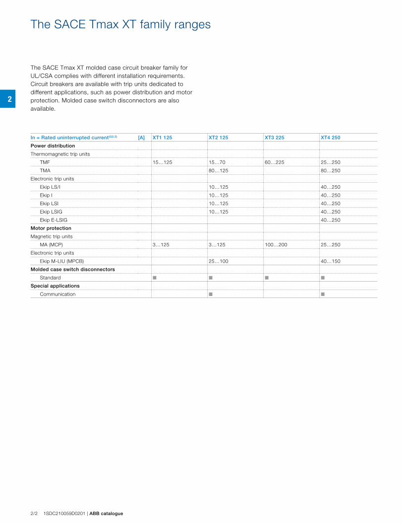
The SACE Tmax XT molded case circuit breaker family for UL/CSA complies with different installation requirements. Circuit breakers are available with trip units dedicated to different applications, such as power distribution and motor protection. Molded case switch disconnectors are also available.
In = Rated uninterrupted current(G2.2) [A] XT1 125 XT2 125 XT3 225 XT4 250
Power distribution
Thermomagnetic trip units
TMF 15…125 15…70 60…225 25…250
TMA 80…125 80…250
Electronic trip units
Ekip LS/I 10…125 40…250
Ekip I 10…125 40…250
Ekip LSI 10…125 40…250
Ekip LSIG 10…125 40…250
Ekip E-LSIG 40…250
Motor protection
Magnetic trip units
MA (MCP) 3…125 3…125 100…200 25…250
Electronic trip units
Ekip M-LIU (MPCB) 25…100 40…150
Molded case switch disconnectors
Standard n n n n
Special applications
Communication n n
2
ABB catalogue | 1SDC210059D0201 2/3
Circuit breakers for power distributionMain characteristics
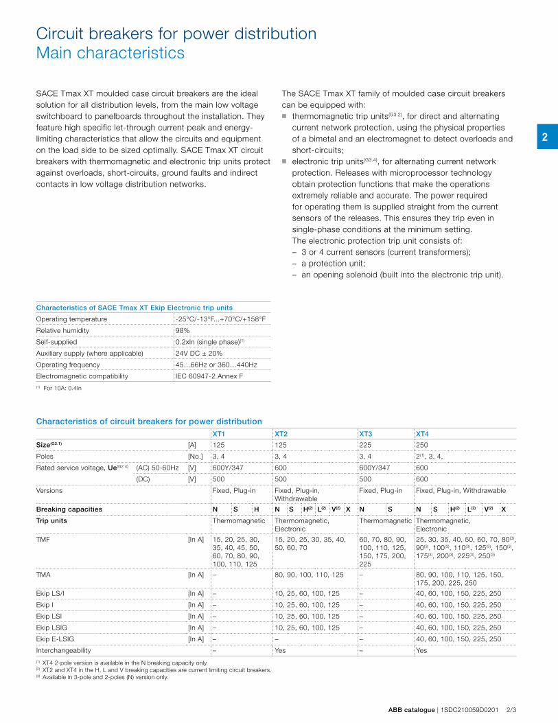
SACE Tmax XT moulded case circuit breakers are the ideal solution for all distribution levels, from the main low voltage switchboard to panelboards throughout the installation. They feature high specific let-through current peak and energy-limiting characteristics that allow the circuits and equipment on the load side to be sized optimally. SACE Tmax XT circuit breakers with thermomagnetic and electronic trip units protect against overloads, short-circuits, ground faults and indirect contacts in low voltage distribution networks.
The SACE Tmax XT family of moulded case circuit breakers can be equipped with: ■ thermomagnetic trip units(G3.2), for direct and alternating
current network protection, using the physical properties of a bimetal and an electromagnet to detect overloads and short-circuits;
■ electronic trip units(G3.4), for alternating current network protection. Releases with microprocessor technology obtain protection functions that make the operations extremely reliable and accurate. The power required for operating them is supplied straight from the current sensors of the releases. This ensures they trip even in single-phase conditions at the minimum setting.
The electronic protection trip unit consists of: – 3 or 4 current sensors (current transformers); – a protection unit; – an opening solenoid (built into the electronic trip unit).
Characteristics of SACE Tmax XT Ekip Electronic trip units
Operating temperature -25°C/-13°F...+70°C/+158°F
Relative humidity 98%
Self-supplied 0.2xIn (single phase)(1)
Auxiliary supply (where applicable) 24V DC ± 20%
Operating frequency 45…66Hz or 360…440Hz
Electromagnetic compatibility IEC 60947-2 Annex F(1) For 10A: 0.4In
Characteristics of circuit breakers for power distribution
XT1 XT2 XT3 XT4
Size(G2.1) [A] 125 125 225 250
Poles [No.] 3, 4 3, 4 3, 4 2(1), 3, 4,
Rated service voltage, Ue(G2.4) (AC) 50-60Hz [V] 600Y/347 600 600Y/347 600
(DC) [V] 500 500 500 600
Versions Fixed, Plug-in Fixed, Plug-in, Withdrawable
Fixed, Plug-in Fixed, Plug-in, Withdrawable
Breaking capacities N S H N S H(2) L(2) V(2) X N S N S H(2) L(2) V(2) X
Trip units Thermomagnetic Thermomagnetic, Electronic
Thermomagnetic Thermomagnetic, Electronic
TMF [In A] 15, 20, 25, 30, 35, 40, 45, 50, 60, 70, 80, 90, 100, 110, 125
15, 20, 25, 30, 35, 40, 50, 60, 70
60, 70, 80, 90, 100, 110, 125, 150, 175, 200, 225
25, 30, 35, 40, 50, 60, 70, 80(3), 90(3), 100(3), 110(3), 125(3), 150(3), 175(3), 200(3), 225(3), 250(3)
TMA [In A] – 80, 90, 100, 110, 125 – 80, 90, 100, 110, 125, 150, 175, 200, 225, 250
Ekip LS/I [In A] – 10, 25, 60, 100, 125 – 40, 60, 100, 150, 225, 250
Ekip I [In A] – 10, 25, 60, 100, 125 – 40, 60, 100, 150, 225, 250
Ekip LSI [In A] – 10, 25, 60, 100, 125 – 40, 60, 100, 150, 225, 250
Ekip LSIG [In A] – 10, 25, 60, 100, 125 – 40, 60, 100, 150, 225, 250
Ekip E-LSIG [In A] – – – 40, 60, 100, 150, 225, 250
Interchangeability – Yes – Yes
(1) XT4 2-pole version is available in the N breaking capacity only.(2) XT2 and XT4 in the H, L and V breaking capacities are current limiting circuit breakers.(3) Available in 3-pole and 2-poles (N) version only.
2
2/4 1SDC210059D0201 | ABB catalogue
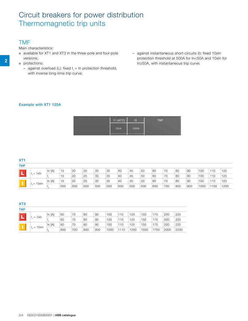
TMFMain characteristics:■ available for XT1 and XT3 in the three-pole and four-pole
versions;■ protections:
– against overload (L): fixed I1 = In protection threshold, with inverse long-time trip curve;
Circuit breakers for power distributionThermomagnetic trip units
XT1
TMF
I1 = 1xInIn [A] 15 20 25 30 35 40 45 50 60 70 80 90 100 110 125
I1 15 20 25 30 35 40 45 50 60 70 80 90 100 110 125
I3 = 10xInIn [A] 15 20 25 30 35 40 45 50 60 70 80 90 100 110 125
I3 500 500 500 500 500 500 500 500 600 700 800 900 1000 1100 1250
XT3
TMF
I1 = 1xInIn [A] 60 70 80 90 100 110 125 150 175 200 225
I1 60 70 80 90 100 110 125 150 175 200 225
I3 = 10xInIn [A] 60 70 80 90 100 110 125 150 175 200 225
I3 600 700 800 900 1000 1110 1250 1500 1750 2000 2250
Example with XT1 125A
– against instantaneous short-circuits (I): fixed 10xIn protection threshold at 500A for In<50A and 10xIn for In≥50A, with instantaneous trip curve;
2
ABB catalogue | 1SDC210059D0201 2/5
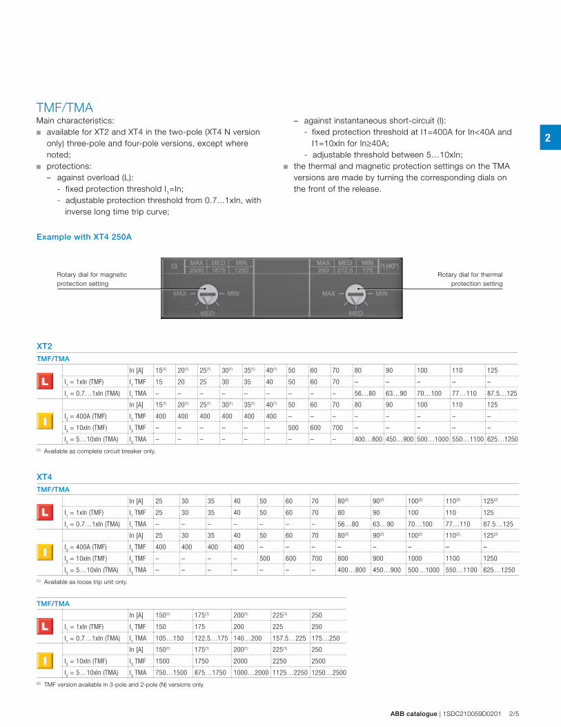
XT2
TMF/TMA
In [A] 15(1) 20(1) 25(1) 30(1) 35(1) 40(1) 50 60 70 80 90 100 110 125
I1 = 1xIn (TMF) I
1 TMF 15 20 25 30 35 40 50 60 70 – – – – –
I1 = 0.7…1xIn (TMA) I
1 TMA – – – – – – – – – 56…80 63…90 70…100 77…110 87.5…125
In [A] 15(1) 20(1) 25(1) 30(1) 35(1) 40(1) 50 60 70 80 90 100 110 125
I3 = 400A (TMF) I
3 TMF 400 400 400 400 400 400 – – – – – – – –
I3 = 10xIn (TMF) I
3 TMF – – – – – – 500 600 700 – – – – –
I3 = 5…10xIn (TMA) I
3 TMA – – – – – – – – – 400…800 450…900 500…1000 550…1100 625…1250
(1) Available as complete circuit breaker only.
XT4
TMF/TMA
In [A] 25 30 35 40 50 60 70 80(2) 90(2) 100(2) 110(2) 125(2)
I1 = 1xIn (TMF) I
1 TMF 25 30 35 40 50 60 70 80 90 100 110 125
I1 = 0.7…1xIn (TMA) I
1 TMA – – – – – – – 56…80 63…90 70…100 77…110 87.5…125
In [A] 25 30 35 40 50 60 70 80(2) 90(2) 100(2) 110(2) 125(2)
I3 = 400A (TMF) I
3 TMF 400 400 400 400 – – – – – – – –
I3 = 10xIn (TMF) I
3 TMF – – – – 500 600 700 800 900 1000 1100 1250
I3 = 5…10xIn (TMA) I
3 TMA – – – – – – – 400…800 450…900 500…1000 550…1100 625…1250
(1) Available as loose trip unit only.
TMF/TMA
In [A] 150(1) 175(1) 200(1) 225(1) 250
I1 = 1xIn (TMF) I
1 TMF 150 175 200 225 250
I1 = 0.7…1xIn (TMA) I
1 TMA 105…150 122.5…175 140…200 157.5…225 175…250
In [A] 150(1) 175(1) 200(1) 225(1) 250
I3 = 10xIn (TMF) I
3 TMF 1500 1750 2000 2250 2500
I3 = 5…10xIn (TMA) I
3 TMA 750…1500 875…1750 1000…2000 1125…2250 1250…2500
(2) TMF version available in 3-pole and 2-pole (N) versions only.
TMF/TMAMain characteristics:■ available for XT2 and XT4 in the two-pole (XT4 N version
only) three-pole and four-pole versions, except where noted;
■ protections: – against overload (L):
- fixed protection threshold I1=In; - adjustable protection threshold from 0.7...1xIn, with
inverse long time trip curve;
Rotary dial for magnetic protection setting
Rotary dial for thermal protection setting
Example with XT4 250A
– against instantaneous short-circuit (I): - fixed protection threshold at I1=400A for In<40A and
I1=10xIn for In≥40A; - adjustable threshold between 5…10xIn;
■ the thermal and magnetic protection settings on the TMA versions are made by turning the corresponding dials on the front of the release.
2
2/6 1SDC210059D0201 | ABB catalogue
Circuit breakers for power distributionElectronic trip units
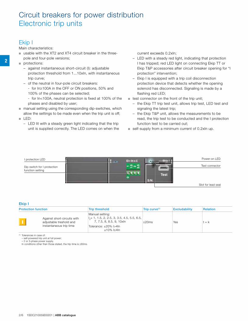
Ekip IMain characteristics: ■ usable with the XT2 and XT4 circuit breaker in the three-
pole and four-pole versions;■ protections:
– against instantaneous short-circuit (I): adjustable protection threshold from 1...10xIn, with instantaneous trip curve;
– of the neutral in four-pole circuit breakers: - for In≥100A in the OFF or ON positions, 50% and
100% of the phases can be selected; - for In<100A, neutral protection is fixed at 100% of the
phases and disabled by user;■ manual setting using the corresponding dip-switches, which
allow the settings to be made even when the trip unit is off; ■ LED:
– LED lit with a steady green light indicating that the trip unit is supplied correctly. The LED comes on when the
Ekip IProtection function Trip threshold Trip curve(1) Excludability Relation
Against short-circuits with adjustable treshold and instantaneous trip time
Manual setting:I3= 1, 1.5, 2, 2.5, 3, 3.5, 4.5, 5.5, 6.5,
7, 7.5, 8, 8.5, 9, 10xIn
Tolerance: ±20% I>4In ±10% I≤4In
≤20ms Yes t = k
(1) Tolerances in case of: – self-powered trip unit at full power; – 2 or 3-phase power supply. In conditions other than those stated, the trip time is ≤60ms.
I protection LED
Test connectorDip switch for I protection function setting
Power-on LED
Slot for lead seal
current exceeds 0.2xIn; – LED with a steady red light, indicating that protection
I has tripped; red LED light on connecting Ekip TT or Ekip T&P accessories after circuit breaker opening for “I protection” intervention;
– Ekip I is equipped with a trip coil disconnection protection device that detects whether the opening solenoid has disconnected. Signaling is made by a flashing red LED;
■ test connector on the front of the trip unit;– the Ekip TT trip test unit, allows trip test, LED test and
signaling the latest trip;– the Ekip T&P unit, allows the measurements to be
read, the trip test to be conducted and the I protection function test to be carried out;
■ self-supply from a minimum current of 0.2xIn up.
2
ABB catalogue | 1SDC210059D0201 2/7
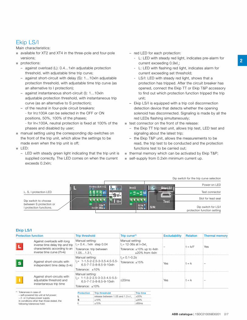
Ekip LS/IMain characteristics: ■ available for XT2 and XT4 in the three-pole and four-pole
versions; ■ protections:
– against overload (L): 0.4...1xIn adjustable protection threshold, with adjustable time trip curve;
– against short-circuit with delay (S): 1...10xIn adjustable protection threshold, with adjustable time trip curve (as an alternative to I protection);
– against instantaneous short-circuit (I): 1...10xIn adjustable protection threshold, with instantaneous trip curve (as an alternative to S protection);
– of the neutral in four-pole circuit breakers: - for In≥100A can be selected in the OFF or ON
positions, 50%, 100% of the phases; - for In<100A, neutral protection is fixed at 100% of the
phases and disabled by user;■ manual setting using the corresponding dip-switches on
the front of the trip unit, which allow the settings to be made even when the trip unit is off;
■ LED: – LED with steady green light indicating that the trip unit is
supplied correctly. The LED comes on when the current exceeds 0.2xIn;
– red LED for each protection: - L: LED with steady red light, indicates pre-alarm for
current exceeding 0.9xI1;- L: LED with flashing red light, indicates alarm for
current exceeding set threshold;- LS/I: LED with steady red light, shows that a
protection has tripped. After the circuit breaker has opened, connect the Ekip TT or Ekip T&P accessory to find out which protection function tripped the trip unit;
– Ekip LS/I is equipped with a trip coil disconnection detection device that detects whether the opening solenoid has disconnected. Signaling is made by all the red LEDs flashing simultaneously;
■ test connector on the front of the release:– the Ekip TT trip test unit, allows trip test, LED test and
signaling about the latest trip;– the Ekip T&P unit, allows the measurements to be
read, the trip test to be conducted and the protection functions test to be carried out;
■ thermal memory which can be activated by Ekip T&P;■ self-supply from 0.2xIn minimum current up.
Ekip LS/IProtection function Trip threshold Trip curve(1) Excludability Relation Thermal memory
Against overloads with long inverse time delay trip and trip characteristic according to an inverse time curve (i2t=k)
Manual setting:I1= 0.4...1xIn step 0.04
Tolerance: trip between 1.05…1.3 I1
Manual setting:t1= 12-36s at I=3xI1Tolerance: ±10% up to 4xIn ±20% from 4xIn
– t = k/l2 Yes
Against short-circuits with independent time delay (t=k)
Manual setting:I2= 1-1.5-2-2.5-3-3.5-4.5-5.5-
6.5-7-7.5-8-8.5-9-10xIn
Tolerance: ±10%
t2= 0.1-0.2s
Tolerance: ±15% Yes t = k –
Against short-circuits with adjustable threshold and instantaneous trip time
Manual setting:I3= 1-1.5-2-2.5-3-3.5-4.5-5.5-
6.5-7-7.5-8-8.5-9-10xIn
Tolerance: ±10%
≤20ms Yes t = k –
(1) Tolerances in case of: – self-powered trip unit at full power; – 2- or 3-phase power supply. In conditions other than those stated, the
following tolerances hold:
Protection Trip threshold Trip timeL release between 1.05 and 1.3 x I1 ±20%S ±10% ±20%I ±15% ≤60ms
L, S, I protection LED Test connector
Dip switch for LS/I protection function setting
Power-on LED
Dip switch for the trip curve selection
Dip switch to choose between S protection or I protection functions.
Slot for lead seal
2
2/8 1SDC210059D0201 | ABB catalogue
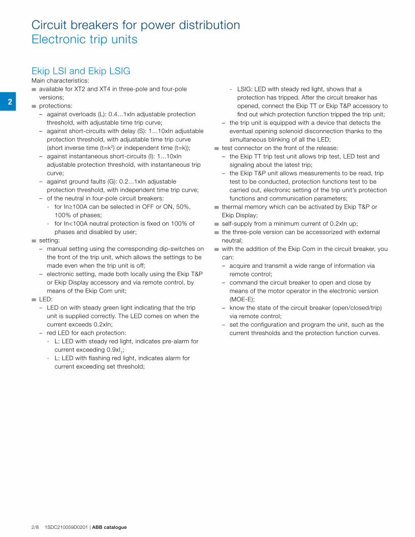
Ekip LSI and Ekip LSIG Main characteristics: ■ available for XT2 and XT4 in three-pole and four-pole
versions;■ protections:
– against overloads (L): 0.4...1xIn adjustable protection threshold, with adjustable time trip curve;
– against short-circuits with delay (S): 1...10xIn adjustable protection threshold, with adjustable time trip curve (short inverse time (t=k2) or independent time (t=k));
– against instantaneous short-circuits (I): 1...10xIn adjustable protection threshold, with instantaneous trip curve;
– against ground faults (G): 0.2...1xIn adjustable protection threshold, with independent time trip curve;
– of the neutral in four-pole circuit breakers: - for In≥100A can be selected in OFF or ON, 50%,
100% of phases;- for In<100A neutral protection is fixed on 100% of
phases and disabled by user;■ setting:
– manual setting using the corresponding dip-switches on the front of the trip unit, which allows the settings to be made even when the trip unit is off;
– electronic setting, made both locally using the Ekip T&P or Ekip Display accessory and via remote control, by means of the Ekip Com unit;
■ LED: – LED on with steady green light indicating that the trip
unit is supplied correctly. The LED comes on when the current exceeds 0.2xIn;
– red LED for each protection: - L: LED with steady red light, indicates pre-alarm for
current exceeding 0.9xI1;- L: LED with flashing red light, indicates alarm for
current exceeding set threshold;
Circuit breakers for power distributionElectronic trip units
- LSIG: LED with steady red light, shows that a protection has tripped. After the circuit breaker has opened, connect the Ekip TT or Ekip T&P accessory to find out which protection function tripped the trip unit;
– the trip unit is equipped with a device that detects the eventual opening solenoid disconnection thanks to the simultaneous blinking of all the LED;
■ test connector on the front of the release:– the Ekip TT trip test unit allows trip test, LED test and
signaling about the latest trip;– the Ekip T&P unit allows measurements to be read, trip
test to be conducted, protection functions test to be carried out, electronic setting of the trip unit’s protection functions and communication parameters;
■ thermal memory which can be activated by Ekip T&P or Ekip Display;
■ self-supply from a minimum current of 0.2xIn up;■ the three-pole version can be accessorized with external
neutral; ■ with the addition of the Ekip Com in the circuit breaker, you
can: – acquire and transmit a wide range of information via
remote control; – command the circuit breaker to open and close by
means of the motor operator in the electronic version (MOE-E);
– know the state of the circuit breaker (open/closed/trip) via remote control;
– set the configuration and program the unit, such as the current thresholds and the protection function curves.
2
ABB catalogue | 1SDC210059D0201 2/9
Ekip LSI – Ekip LSIGProtection function Trip threshold Trip curve(1) Excludability Relation Thermal
memory
Against overloads with long inverse time delay trip and trip characteristic according to an inverse time curve (i2t=k)
Manual setting:I1= 0.4...1xIn step 0.02
Tolerance: trip between 1.05…1.3 I1 (IEC 60947-2)
Manual setting:t1 = 3-12-36-60s at I=3xI1Tolerance: ±10% up to 4xIn ±20% from 4xIn
– t = k/l2 Yes
Electronic setting:I1= 0.4...1xIn step 0.01
Tolerance: trip between 1.05…1.3 I1 (IEC 60947-2)
Electronic setting:t1 = 3...60s at I=3xI1 step 0.5
Tolerance: ±10% up to 4xIn ±20% from 4xIn
– t = k/l2 Yes
Against short-circuits with inverse short (t=k/I2) or independent (t=k) time delay trip
Manual setting:I2 = 1-1.5-2-2.5-3-3.5-4.5-5.5-
6.5-7-7.5-8-8.5-9-10xIn
Tolerance: ±10%
Manual setting:t2= 0.05-0.10-0.20-0.40s
at 10xIn
Tolerance: ±10% up to 4xIn ±20% from 4xIn
Yes t = k/l2 –
Electronic setting:I2 = 1...10xIn step 0.1
Tolerance: ±10%
Electronic setting:t2 = 0.05...0.40s at 10xIn step 0.01
Tolerance: ±10% up to 4xIn ±20% from 4xIn
Yes t = k/l2 –
Manual setting:I2 = 1-1.5-2-2.5-3-3.5-4.5-5.5-
6.5-7-7.5-8-8.5-9-10xIn
Tolerance: ±10%
Manual setting:t2 = 0.05-0.1-0.2-0.4s
Tolerance: ±15% t2>100ms ±20% t2≤100ms
Yes t = k –
Electronic setting:I2 = 1...10xIn step 0.1
Tolerance: ±10%
Electronic setting:t2 = 0.05...0.4s step 0.01
Tolerance: ±15% t2>100ms ±20% t2≤100ms
Yes t = k –
Against short-circuits with adjustable threshold and instantaneous trip time
Manual setting:I3 = 1-1.5-2-2.5-3-3.5-4.5-5.5-
6.5-7-7.5-8-8.5-9-10xIn
Tolerance: ±10%
≤40ms Yes t = k –
Electronic setting:I3 = 1...10xIn step 0.1
Tolerance: ±10%≤40ms Yes t = k –
Against ground fault with independent time delay trip(2)
Manual setting:
I4 = 0.2-0.25-0.45-0.55-0.75- 0.8-1xIn
Tolerance: ±10%
Manual setting:t4 = 0.1-0.2-0.4-0.8s
Tolerance: ±15%Yes t = k –
Electronic setting:I4 = 0.2...1xIn step 0.02
Tolerance: ±10%
Electronic setting:t4 = 0.1...0.8s step 0.05
Tolerance: ±15%Yes t = k –
L, S, I, G protection LED
Test connectorDip switch for the S trip curves selection
Power-on LED
Dip switch for LSIG protection function setting
Dip switch for the trip curve selection
Selection for remote or local setting
Selection for manual or electronic setting
(1) Tolerances in case of: – self-powered trip unit at full power; – 2- or 3-phase power supply. In conditions other than those stated, the
following tolerances hold:
Protection Trip threshold Trip timeL release between 1.05 and 1.3 x I1 ±20%S ±10% ±20%I ±15% ≤60msG ±15% ±20%
Slot for lead seal
(2) Protection G is inhibited for currents higher than 2 In.
2
2/10 1SDC210059D0201 | ABB catalogue
Circuit breakers for power distributionElectronic trip units
Ekip E-LSIGMain characteristics:■ available for XT4 in three-pole and four-pole versions;■ protections:
– against overloads (L): 0.4...1xIn adjustable protection threshold, with adjustable time trip curve;
– against short-circuits with delay (S): 1...10xIn adjustable protection threshold, with adjustable time trip curve;
– against instantaneous short-circuits (I): 1...10xIn adjust-able protection threshold, with instantaneous trip curve;
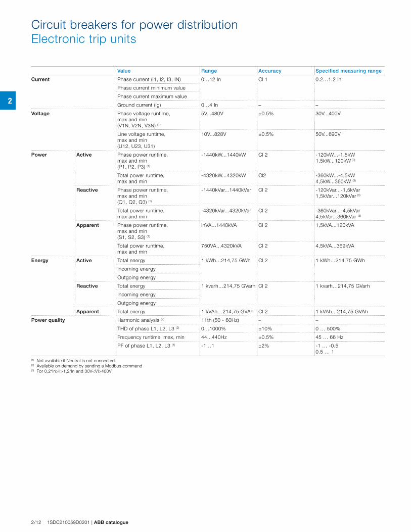
– of the neutral in four-pole circuit breakers;■ measurements:
– available from 0.2xIn in Vaux mode and starting from 0.5xIn in self supply mode; external current or voltage transformers are not required. See table for ranges and accuracy;
– Currents: three phases (L1, L2, L3), neutral (Ne) and ground fault;
– Voltage: phase-phase, phase-neutral;– Power: active, reactive and apparent;– Power factor;– Frequency and peak factor;– Energy: active, reactive, apparent, counter;
■ setting:– manual setting using the corresponding dip-switches on
the front of the trip unit, which allow the settings to be made even when the trip unit is off;
– electronic setting, made both locally using Ekip T&P or Ekip Display accessory and via remote control, by means of the dialog unit Ekip Com. The electronic settings have a wider range and more regulation steps.
Use of electronic setting allows other functions to be activated:- function for protection against ground faults (G):
0.2..1xIn adjustable protection threshold, with a time constant trip curve;
- over voltage protection 0.5…0.95 Un with a time constant trip curve;
- under voltage protection 1.05…1.2 Un with a time constant trip curve;
■ LED:– LED on with steady green light indicating that the trip
unit is supplied correctly. The LED comes on when the current exceeds 0.2xIn;
– red LED for each protection:- L: LED with steady red light, indicates pre-alarm for
current exceeding 0.9xI1;- L: LED with flashing red light, indicates alarm for
current exceeding set threshold;- fixed LED MAN/ELT shows the version of active
parameters;- LSIG: LED with steady red light, shows that a
protection has tripped. After the circuit breaker has opened, connect the Ekip TT or Ekip T&P accessory to find out which protection function tripped the trip unit;
– the trip unit is equipped with a device that detects the opening solenoid disconnection. It is communicated by the simultaneous blinking of all the LEDs;
■ test connector on the front of the release:– the Ekip TT trip test unit, allows trip test, LED test and
signaling about the latest trip;– the Ekip T&P unit allows measurements to be read, trip
test to be conducted, protection functions test to be carried out, electronic setting of the trip unit’s protection functions and communication parameters;
■ self-supply from a minimum current of 0.2xIn up; measurements starting from 0.5xIn;
■ the three-pole version can be accessorized with external neutral current transformer and external neutral voltage connection kit;
■ with the addition of Ekip Com in the circuit breaker, you can:– acquire and transmit a wide range of information via
remote control;– command the circuit breaker to open and close by
means of the motor operator in the electronic version (MOE-E);
– know the circuit breaker's state (open/closed/trip) via remote control;
– set the configuration and program the unit, such as the current thresholds and the protection function curves.
2
ABB catalogue | 1SDC210059D0201 2/11
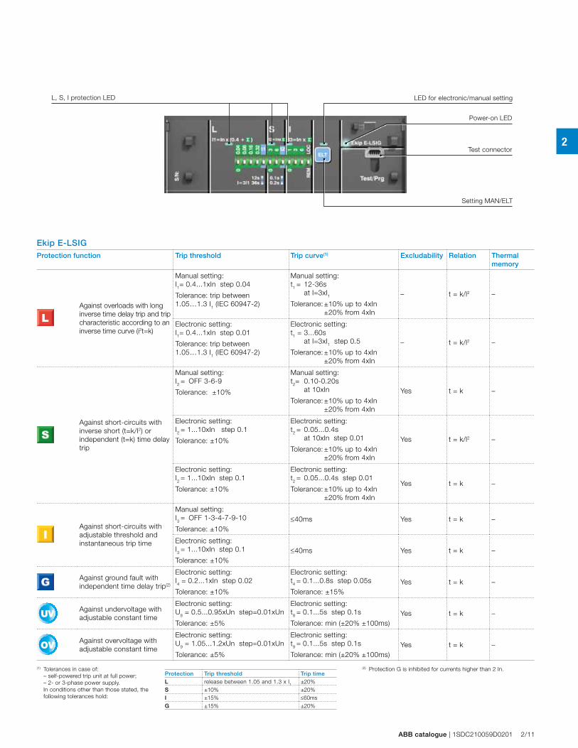
Test connector
Power-on LED
L, S, I protection LED LED for electronic/manual setting
Setting MAN/ELT
Ekip E-LSIGProtection function Trip threshold Trip curve(1) Excludability Relation Thermal
memory
Against overloads with long inverse time delay trip and trip characteristic according to an inverse time curve (i2t=k)
Manual setting:I1= 0.4...1xIn step 0.04
Tolerance: trip between 1.05…1.3 I1 (IEC 60947-2)
Manual setting:t1 = 12-36s at I=3xI1Tolerance: ±10% up to 4xIn ±20% from 4xIn
– t = k/l2 –
Electronic setting:I1= 0.4...1xIn step 0.01
Tolerance: trip between 1.05…1.3 I1 (IEC 60947-2)
Electronic setting:t1 = 3...60s at I=3xI1 step 0.5
Tolerance: ±10% up to 4xIn ±20% from 4xIn
– t = k/l2 –
Against short-circuits with inverse short (t=k/I2) or independent (t=k) time delay trip
Manual setting:I2 = OFF 3-6-9
Tolerance: ±10%
Manual setting:t2= 0.10-0.20s at 10xIn
Tolerance: ±10% up to 4xIn ±20% from 4xIn
Yes t = k –
Electronic setting:I2 = 1...10xIn step 0.1
Tolerance: ±10%
Electronic setting:t2 = 0.05...0.4s at 10xIn step 0.01
Tolerance: ±10% up to 4xIn ±20% from 4xIn
Yes t = k/l2 –
Electronic setting:I2 = 1...10xIn step 0.1
Tolerance: ±10%
Electronic setting:t2 = 0.05...0.4s step 0.01
Tolerance: ±10% up to 4xIn ±20% from 4xIn
Yes t = k –
Against short-circuits with adjustable threshold and instantaneous trip time
Manual setting:I3 = OFF 1-3-4-7-9-10
Tolerance: ±10%≤40ms Yes t = k –
Electronic setting:I3 = 1...10xIn step 0.1
Tolerance: ±10%≤40ms Yes t = k –
Against ground fault with independent time delay trip(2)
Electronic setting:I4 = 0.2...1xIn step 0.02
Tolerance: ±10%
Electronic setting:t4 = 0.1...0.8s step 0.05s
Tolerance: ±15%Yes t = k –
UV
Against undervoltage with adjustable constant time
Electronic setting:U8 = 0.5...0.95xUn step=0.01xUn
Tolerance: ±5%
Electronic setting:t8 = 0.1...5s step 0.1s
Tolerance: min (±20% ±100ms)Yes t = k –
OV Against overvoltage with adjustable constant time
Electronic setting:U9 = 1.05...1.2xUn step=0.01xUn
Tolerance: ±5%
Electronic setting:t9 = 0.1...5s step 0.1s
Tolerance: min (±20% ±100ms)Yes t = k –
(1) Tolerances in case of: – self-powered trip unit at full power; – 2- or 3-phase power supply. In conditions other than those stated, the
following tolerances hold:
Protection Trip threshold Trip timeL release between 1.05 and 1.3 x I1 ±20%S ±10% ±20%I ±15% ≤60msG ±15% ±20%
(2) Protection G is inhibited for currents higher than 2 In.
2
2/12 1SDC210059D0201 | ABB catalogue
Circuit breakers for power distributionElectronic trip units
Value Range Accuracy Specified measuring range
Current Phase current (I1, I2, I3, IN) 0…12 In Cl 1 0.2…1.2 In
Phase current minimum value
Phase current maximum value
Ground current (Ig) 0…4 In – –
Voltage Phase voltage runtime, max and min (V1N, V2N, V3N) (1)
5V...480V ±0.5% 30V...400V
Line voltage runtime, max and min(U12, U23, U31)
10V...828V ±0.5% 50V...690V
Power Active Phase power runtime, max and min(P1, P2, P3) (1)
-1440kW...1440kW Cl 2 -120kW...-1,5kW1,5kW...120kW (3)
Total power runtime, max and min
-4320kW...4320kW Cl2 -360kW...-4,5kW4,5kW...360kW (3)
Reactive Phase power runtime, max and min(Q1, Q2, Q3) (1)
-1440kVar...1440kVar Cl 2 -120kVar...-1,5kVar1,5kVar...120kVar (3)
Total power runtime, max and min
-4320kVar...4320kVar Cl 2 -360kVar...-4,5kVar4,5kVar...360kVar (3)
Apparent Phase power runtime, max and min(S1, S2, S3) (1)
InVA...1440kVA Cl 2 1,5kVA...120kVA
Total power runtime, max and min
750VA...4320kVA Cl 2 4,5kVA...369kVA
Energy Active Total energy 1 kWh…214,75 GWh Cl 2 1 kWh…214,75 GWh
Incoming energy
Outgoing energy
Reactive Total energy 1 kvarh…214,75 GVarh Cl 2 1 kvarh…214,75 GVarh
Incoming energy
Outgoing energy
Apparent Total energy 1 kVAh…214,75 GVAh Cl 2 1 kVAh…214,75 GVAh
Power quality Harmonic analysis (2) 11th (50 - 60Hz) – –
THD of phase L1, L2, L3 (2) 0…1000% ±10% 0 … 500%
Frequency runtime, max, min 44...440Hz ±0.5% 45 … 66 Hz
PF of phase L1, L2, L3 (1) -1…1 ±2% -1 … -0.50.5 … 1
(1) Not available if Neutral is not connected(2) Available on demand by sending a Modbus command(3) For 0,2*In>Ii>1,2*In and 30V<Vi>400V
2
ABB catalogue | 1SDC210059D0201 2/13
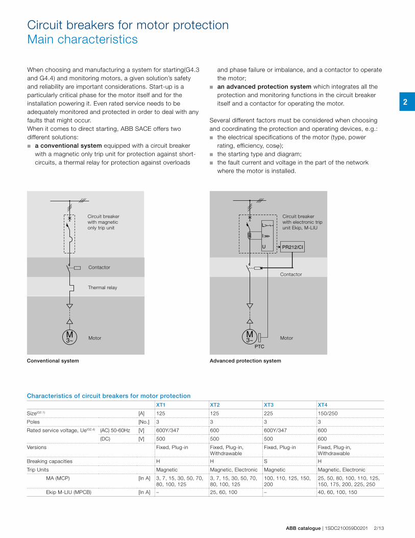
PTC
PR212/CI
Motor
Circuit breaker with magnetic only trip unit
Thermal relay
Contactor
Motor
Circuit breaker with electronic trip unit Ekip, M-LIU
Contactor
Conventional system Advanced protection system
When choosing and manufacturing a system for starting(G4.3 and G4.4) and monitoring motors, a given solution’s safety and reliability are important considerations. Start-up is a particularly critical phase for the motor itself and for the installation powering it. Even rated service needs to be adequately monitored and protected in order to deal with any faults that might occur.When it comes to direct starting, ABB SACE offers two different solutions:■ a conventional system equipped with a circuit breaker
with a magnetic only trip unit for protection against short-circuits, a thermal relay for protection against overloads
Circuit breakers for motor protectionMain characteristics
and phase failure or imbalance, and a contactor to operate the motor;
■ an advanced protection system which integrates all the protection and monitoring functions in the circuit breaker itself and a contactor for operating the motor.
Several different factors must be considered when choosing and coordinating the protection and operating devices, e.g.:■ the electrical specifications of the motor (type, power
rating, efficiency, cosϕ);■ the starting type and diagram;■ the fault current and voltage in the part of the network
where the motor is installed.
Characteristics of circuit breakers for motor protectionXT1 XT2 XT3 XT4
Size(G2.1) [A] 125 125 225 150/250
Poles [No.] 3 3 3 3
Rated service voltage, Ue(G2.4) (AC) 50-60Hz [V] 600Y/347 600 600Y/347 600
(DC) [V] 500 500 500 600
Versions Fixed, Plug-in Fixed, Plug-in, Withdrawable
Fixed, Plug-in Fixed, Plug-in, Withdrawable
Breaking capacities H H S H
Trip Units Magnetic Magnetic, Electronic Magnetic Magnetic, Electronic
MA (MCP) [In A] 3, 7, 15, 30, 50, 70, 80, 100, 125
3, 7, 15, 30, 50, 70, 80, 100, 125
100, 110, 125, 150, 200
25, 50, 80, 100, 110, 125, 150, 175, 200, 225, 250
Ekip M-LIU (MPCB) [In A] – 25, 60, 100 – 40, 60, 100, 150
2
2/14 1SDC210059D0201 | ABB catalogue
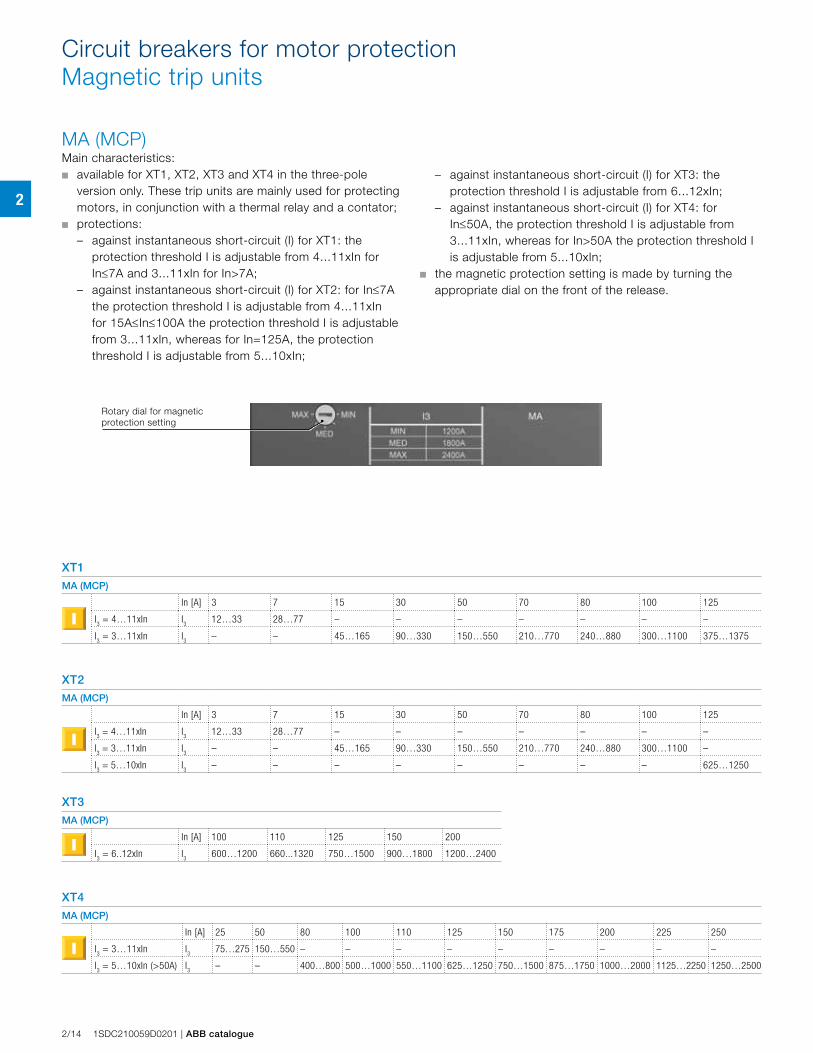
MA (MCP)Main characteristics: ■ available for XT1, XT2, XT3 and XT4 in the three-pole
version only. These trip units are mainly used for protecting motors, in conjunction with a thermal relay and a contator;
■ protections: – against instantaneous short-circuit (I) for XT1: the
protection threshold I is adjustable from 4...11xIn for In≤7A and 3...11xIn for In>7A;
– against instantaneous short-circuit (I) for XT2: for In≤7A the protection threshold I is adjustable from 4...11xIn for 15A≤In≤100A the protection threshold I is adjustable from 3...11xIn, whereas for In=125A, the protection threshold I is adjustable from 5...10xIn;
Circuit breakers for motor protectionMagnetic trip units
XT1
MA (MCP)
In [A] 3 7 15 30 50 70 80 100 125
I3 = 4…11xIn I
312…33 28…77 – – – – – – –
I3 = 3…11xIn I
3 – – 45…165 90…330 150…550 210…770 240…880 300…1100 375…1375
XT2
MA (MCP)
In [A] 3 7 15 30 50 70 80 100 125
I3 = 4…11xIn I
312…33 28…77 – – – – – – –
I3 = 3…11xIn I
3– – 45…165 90…330 150…550 210…770 240…880 300…1100 –
I3 = 5…10xIn I
3 – – – – – – – – 625…1250
XT3
MA (MCP)
In [A] 100 110 125 150 200
I3 = 6..12xIn I
3600…1200 660...1320 750…1500 900…1800 1200…2400
XT4
MA (MCP)
In [A] 25 50 80 100 110 125 150 175 200 225 250
I3 = 3…11xIn I
375…275 150…550 – – – – – – – – –
I3 = 5…10xIn (>50A) I
3– – 400…800 500…1000 550…1100 625…1250 750…1500 875…1750 1000…2000 1125…2250 1250…2500
Rotary dial for magnetic protection setting
– against instantaneous short-circuit (I) for XT3: the protection threshold I is adjustable from 6...12xIn;
– against instantaneous short-circuit (I) for XT4: for In≤50A, the protection threshold I is adjustable from 3...11xIn, whereas for In>50A the protection threshold I is adjustable from 5...10xIn;
■ the magnetic protection setting is made by turning the appropriate dial on the front of the release.
2
ABB catalogue | 1SDC210059D0201 2/15
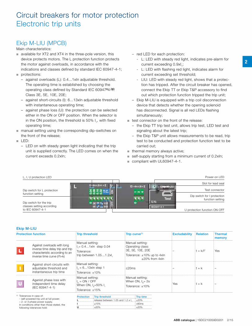
Ekip M-LIU (MPCB)Main characteristics: ■ available for XT2 and XT4 in the three-pole version, this
device protects motors. The L protection function protects the motor against overloads, in accordance with the indications and classes defined by standard IEC 60947-4-1;
■ protections:– against overloads (L): 0.4...1xIn adjustable threshold.
The operating time is established by choosing the operating class defined by Standard IEC 60947-4-1: Class 3E, 5E, 10E, 20E;
– against short-circuits (I): 6...13xIn adjustable threshold with instantaneous operating time;
– against phase loss (U): the protection can be selected either in the ON or OFF position. When the selector is in the ON position, the threshold is 50% I1, with fixed operating time;
■ manual setting using the corresponding dip-switches on the front of the release;
■ LED: – LED on with steady green light indicating that the trip
unit is supplied correctly. The LED comes on when the current exceeds 0.2xIn;
Circuit breakers for motor protectionElectronic trip units
– red LED for each protection: - L: LED with steady red light, indicates pre-alarm for
current exceeding 0.9xI1;- L: LED with flashing red light, indicates alarm for
current exceeding set threshold;- LIU: LED with steady red light, shows that a protec-
tion has tripped. After the circuit breaker has opened, connect the Ekip TT or Ekip T&P accessory to find out which protection function tripped the trip unit;
– Ekip M-LIU is equipped with a trip coil disconnection device that detects whether the opening solenoid has disconnected. Signal is all red LEDs flashing simultaneously;
■ test connector on the front of the release:– the Ekip TT trip test unit, allows trip test, LED test and
signaling about the latest trip;– the Ekip T&P unit allows measurements to be read, trip
test to be conducted and protection function test to be carried out;
■ thermal memory always active;■ self-supply starting from a minimum current of 0.2xIn;■ compliant with UL60947-4-1.
Ekip M-LIU Protection function Trip threshold Trip curve(1) Excludability Relation Thermal
memory
Against overloads with long inverse time delay trip and trip characteristic according to an inverse time curve (i2t=k)
Manual setting:I1= 0.4...1xIn step 0.04
Tolerance:trip between 1.05…1.2xI1
Manual setting:Operating class: 3E, 5E, 10E, 20E
Tolerance: ±10% up to 4xIn ±20% from 4xIn
– t = k/l2 Yes
Against short-circuits with adjustable threshold and instantaneous trip time
Manual setting:I3 = 6...13xIn step 1
Tolerance: ±10%≤20ms – t = k –
Aganist phase loss with independent time delay (IEC 60947-4-1)
Manual setting:I6 = ON / OFF When ON, I6=50% I1
Tolerance: ±15%
Manual setting:When ON, t6= 2s
Tolerance: ±10%Yes t = k –
L, I, U protection LED
Test connectorDip switch for L protection function setting
Power-on LED
Dip switch for I protection function setting
Dip switch for the trip classes setting according to IEC 60947-4-1 U protection function ON-OFF
(1) Tolerances in case of: – self-powered trip unit at full power; – 2- or 3-phase power supply. In conditions other than those stated, the
following tolerances hold:
Protection Trip threshold Trip timeL release between 1.05 and 1.2 x I1 ±20%I ±15% ≤60msU ±20% ±20%
Slot for lead seal
■ se
2
2/16 1SDC210059D0201 | ABB catalogue
XT1D
XT3D
XT4D
XT2D
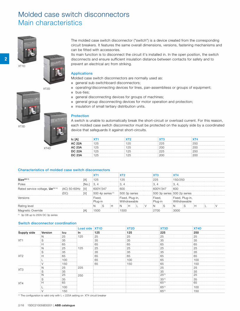
The molded case switch disconnector ("switch") is a device created from the corresponding circuit breakers. It features the same overall dimensions, versions, fastening mechanisms and can be fitted with accessories.Its main function is to disconnect the circuit it's installed in. In the open position, the switch disconnects and ensure sufficient insulation distance between contacts for safety and to prevent an electrical arc from striking.
ApplicationsMolded case switch disconnectors are normally used as: ■ general sub-switchboard disconnectors;■ operating/disconnecting devices for lines, pan-assembliess or groups of equipment;■ bus-ties;■ general disconnecting devices for groups of machines; ■ general group disconnecting devices for motor operation and protection;■ insulation of small tertiary distribution units.
ProtectionA switch is unable to automatically break the short-circuit or overload current. For this reason, each molded case switch disconnector must be protected on the supply side by a coordinated device that safeguards it against short-circuits.
Molded case switch disconnectorsMain characteristics
Characteristics of molded case switch disconnectorsXT1 XT2 XT3 XT4
Size(G2.1) [A] 125 125 225 150/250
Poles [No.] 3, 4 3, 4 3, 4 3, 4,
Rated service voltage, Ue(G2.4) (AC) 50-60Hz [V] 600Y/347 600 600Y/347 600
(DC) [V] 500 4p series (1) 500 3p series 500 3p series 500 2p series
Versions Fixed, Plug-in
Fixed, Plug-in, Withdrawable
Fixed, Plug-in
Fixed, Plug-in, Withdrawable
Rating level N S H N H L V N S N S H L V
Magnetic Override [A] 1500 1500 2700 3000(1) 3p CB up to 250V DC 3p series
Switch disconnector coordinationLoad side XT1D XT2D XT3D XT4D
Supply side Version Icu In 125 125 225 250
XT1N 25 125 25 25 25 25S 35 35 35 35 35H 65 65 65 65 65
XT2
N 25 125 25 25 25 25S 35 35 35 35 35H 65 65 65 65 65L 100 65 100 65 100V 150 65 150 65 150
XT3N 25 225 25 25S 35 35 35
XT4
N 25 250 25(1) 25
S 35 35(1) 35H 65 65(1) 65
L 100 65(1) 100V 150 65(1) 150
(1) The configuration is valid only with I1 < 225A setting on XT4 circuit breaker
Ic [A] XT1 XT2 XT3 XT4AC 22A 125 125 225 250AC 23A 125 125 200 200DC 22A 125 125 225 250DC 23A 125 125 200 200
2
ABB catalogue | 1SDC210059D0201 2/17
Current LimitingElectrical characteristics
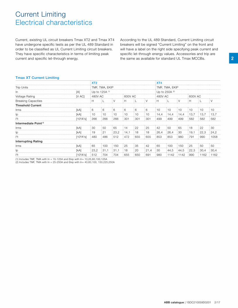
Current, existing UL circuit breakers Tmax XT2 and Tmax XT4 have undergone specific tests as per the UL 489 Standard in order to be classified as UL Current Limiting circuit breakers. They have specific characteristics in terms of limiting peak current and specific let-through energy.
According to the UL 489 Standard, Current Limiting circuit breakers will be signed “Current Limiting” on the front and will have a label on the right side specifying peak current and specific let-through energy values. Accessories and trip are the same as available for standard UL Tmax MCCBs.
Tmax XT Current Limiting XT2 XT4
Trip Units TMF, TMA, EKIP TMF, TMA, EKIP
In [A] Up to 125A (1) Up to 250A (2)
Voltage Rating [V AC] 480V AC 600V AC 480V AC 600V AC
Breaking Capacities H L V H L V H L V H L V
Threshold Current
Irms [kA] 6 6 6 6 6 6 10 10 10 10 10 10
Ip [kA] 10 10 10 10 10 10 14,4 14,4 14,4 13,7 13,7 13,7
I2t [106A2s] 266 266 266 301 301 301 499 499 499 582 582 582
Intermediate Point ©
Irms [kA] 30 50 65 14 22 25 42 50 65 18 22 30
Ip [kA] 19 21 23,2 14,1 18 18 26,4 26,4 30 19,1 22,3 24,2
I2t [106A2s] 480 486 512 472 655 655 853 853 980 791 990 1058
Interrupting Rating
Irms [kA] 65 100 150 25 35 42 65 100 150 25 50 50
Ip [kA] 23,2 31,1 31,1 18 20 21,4 30 44,5 44,5 22,3 30,4 30,4
I2t [106A2s] 512 704 704 655 650 691 980 1142 1142 990 1162 1162(1) Includes TMF, TMA with In = 15-125A and Ekip with In= 10,25,60,100,125A(2) Includes TMF, TMA with In = 25-250A and Ekip with In= 40,60,100, 150,225,250A
2
2/18 1SDC210059D0201 | ABB catalogue
24 V+
–
Modbus
HMI030Internal Bus
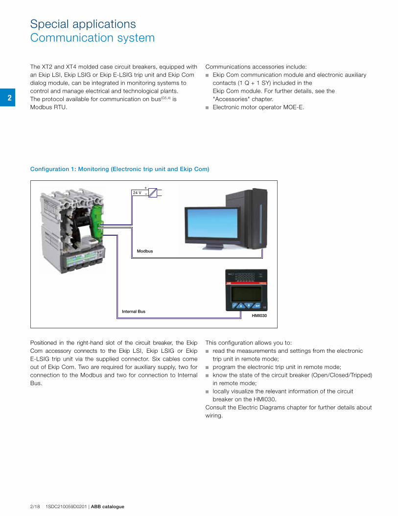
The XT2 and XT4 molded case circuit breakers, equipped with an Ekip LSI, Ekip LSIG or Ekip E-LSIG trip unit and Ekip Com dialog module, can be integrated in monitoring systems to control and manage electrical and technological plants.The protocol available for communication on bus(G5,4) is Modbus RTU.
Special applicationsCommunication system
Communications accessories include:■ Ekip Com communication module and electronic auxiliary
contacts (1 Q + 1 SY) included in the Ekip Com module. For further details, see the "Accessories" chapter.
■ Electronic motor operator MOE-E.
Configuration 1: Monitoring (Electronic trip unit and Ekip Com)
Positioned in the right-hand slot of the circuit breaker, the Ekip Com accessory connects to the Ekip LSI, Ekip LSIG or Ekip E-LSIG trip unit via the supplied connector. Six cables come out of Ekip Com. Two are required for auxiliary supply, two for connection to the Modbus and two for connection to Internal Bus.
This configuration allows you to:■ read the measurements and settings from the electronic
trip unit in remote mode;■ program the electronic trip unit in remote mode;■ know the state of the circuit breaker (Open/Closed/Tripped)
in remote mode;■ locally visualize the relevant information of the circuit
breaker on the HMI030. Consult the Electric Diagrams chapter for further details about wiring.
2
ABB catalogue | 1SDC210059D0201 2/19
24 V+
–
+Modbus
24 V+
–
+
HMI030
Modbus
Internal Bus
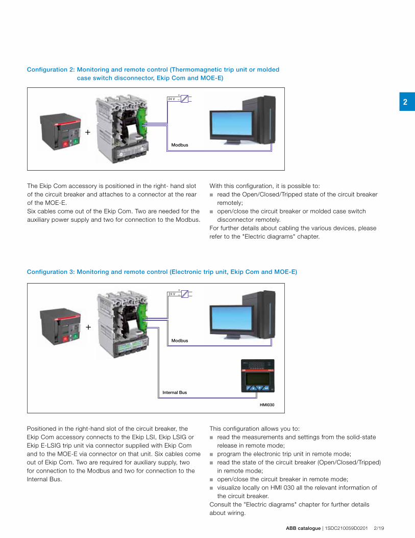
Configuration 2: Monitoring and remote control (Thermomagnetic trip unit or molded case switch disconnector, Ekip Com and MOE-E)
The Ekip Com accessory is positioned in the right- hand slot of the circuit breaker and attaches to a connector at the rear of the MOE-E. Six cables come out of the Ekip Com. Two are needed for the auxiliary power supply and two for connection to the Modbus.
With this configuration, it is possible to:■ read the Open/Closed/Tripped state of the circuit breaker
remotely;■ open/close the circuit breaker or molded case switch
disconnector remotely.For further details about cabling the various devices, please refer to the "Electric diagrams" chapter.
Configuration 3: Monitoring and remote control (Electronic trip unit, Ekip Com and MOE-E)
Positioned in the right-hand slot of the circuit breaker, the Ekip Com accessory connects to the Ekip LSI, Ekip LSIG or Ekip E-LSIG trip unit via connector supplied with Ekip Com and to the MOE-E via connector on that unit. Six cables come out of Ekip Com. Two are required for auxiliary supply, two for connection to the Modbus and two for connection to the Internal Bus.
This configuration allows you to: ■ read the measurements and settings from the solid-state
release in remote mode;■ program the electronic trip unit in remote mode; ■ read the state of the circuit breaker (Open/Closed/Tripped)
in remote mode;■ open/close the circuit breaker in remote mode;■ visualize locally on HMI 030 all the relevant information of
the circuit breaker.Consult the "Electric diagrams" chapter for further details about wiring.
2
2/20 1SDC210059D0201 | ABB catalogue
24 V+
–
HMI030Internal Bus
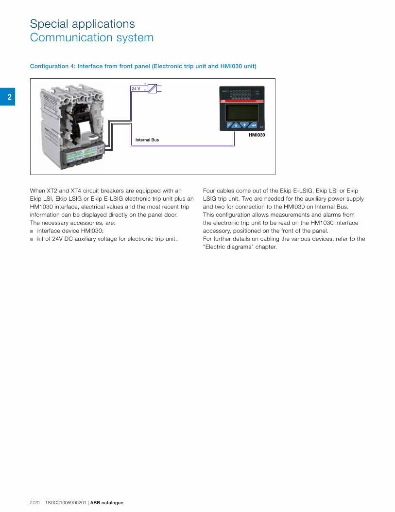
Configuration 4: Interface from front panel (Electronic trip unit and HMI030 unit)
When XT2 and XT4 circuit breakers are equipped with an Ekip LSI, Ekip LSIG or Ekip E-LSIG electronic trip unit plus an HM1030 interface, electrical values and the most recent trip information can be displayed directly on the panel door. The necessary accessories, are:■ interface device HMI030;■ kit of 24V DC auxiliary voltage for electronic trip unit.
Four cables come out of the Ekip E-LSIG, Ekip LSI or Ekip LSIG trip unit. Two are needed for the auxiliary power supply and two for connection to the HMI030 on Internal Bus. This configuration allows measurements and alarms from the electronic trip unit to be read on the HM1030 interface accessory, positioned on the front of the panel.For further details on cabling the various devices, refer to the "Electric diagrams" chapter.
Special applicationsCommunication system
2
ABB catalogue | 1SDC210059D0201 2/21
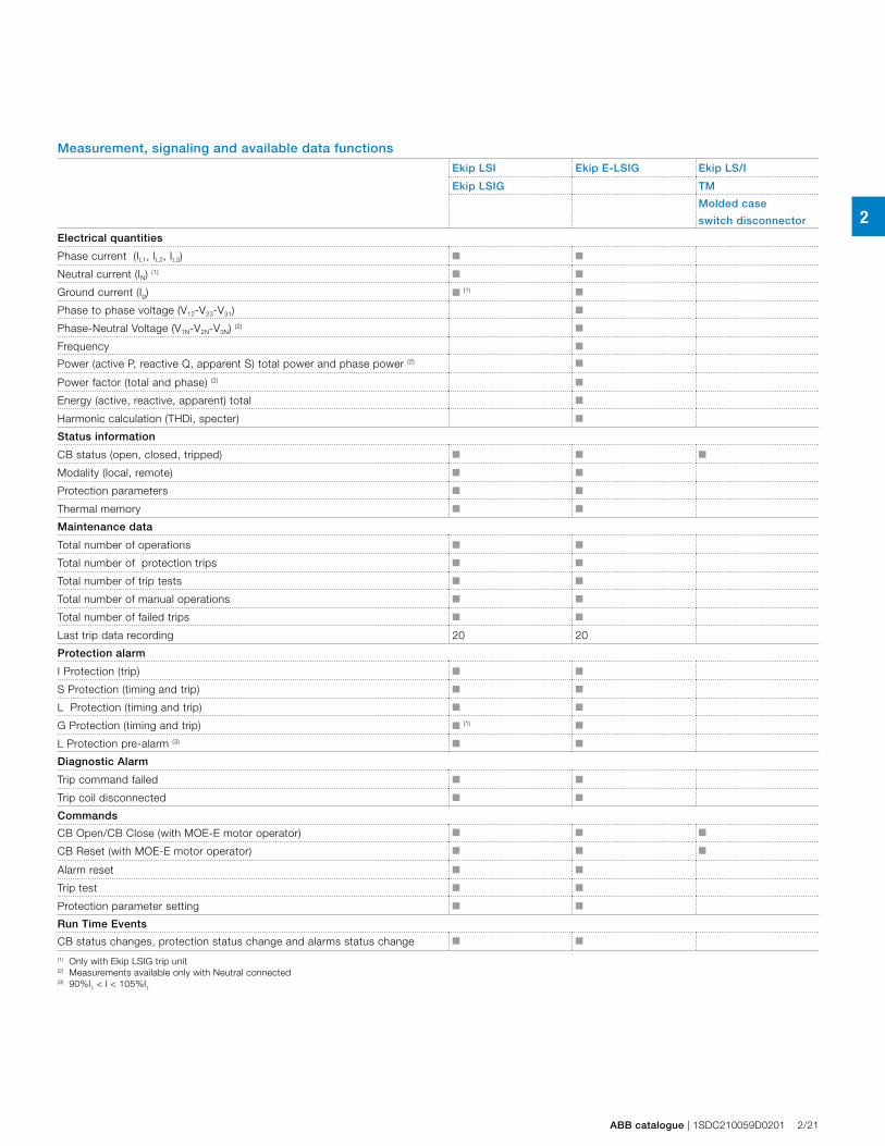
Measurement, signaling and available data functions
Ekip LSI Ekip E-LSIG Ekip LS/I
Ekip LSIG TM
Molded case
switch disconnector
Electrical quantities
Phase current (IL1, IL2, IL3) ■ ■
Neutral current (IN) (1) ■ ■
Ground current (Ig) ■ (1) ■
Phase to phase voltage (V12-V23-V31) ■
Phase-Neutral Voltage (V1N-V2N-V3N) (2) ■
Frequency ■
Power (active P, reactive Q, apparent S) total power and phase power (2) ■
Power factor (total and phase) (2) ■
Energy (active, reactive, apparent) total ■
Harmonic calculation (THDi, specter) ■
Status information
CB status (open, closed, tripped) ■ ■ ■
Modality (local, remote) ■ ■
Protection parameters ■ ■
Thermal memory ■ ■
Maintenance data
Total number of operations ■ ■
Total number of protection trips ■ ■
Total number of trip tests ■ ■
Total number of manual operations ■ ■
Total number of failed trips ■ ■
Last trip data recording 20 20
Protection alarm
I Protection (trip) ■ ■
S Protection (timing and trip) ■ ■
L Protection (timing and trip) ■ ■
G Protection (timing and trip) ■ (1) ■
L Protection pre-alarm (3) ■ ■
Diagnostic Alarm
Trip command failed ■ ■
Trip coil disconnected ■ ■
Commands
CB Open/CB Close (with MOE-E motor operator) ■ ■ ■
CB Reset (with MOE-E motor operator) ■ ■ ■
Alarm reset ■ ■
Trip test ■ ■
Protection parameter setting ■ ■
Run Time Events
CB status changes, protection status change and alarms status change ■ ■
(1) Only with Ekip LSIG trip unit(2) Measurements available only with Neutral connected(3) 90%I1 < I < 105%I1

2
2/22 1SDC210059D0201 | ABB catalogue
3
ABB catalog | 1SDC210059D0201 3/1
Accessories
Versions and types
Fixed part of Plug-in and withdrawable versions 3/2
Conversion kits 3/3
Mechanical accessories
Connection terminals 3/5
Terminal covers and phase separators 3/12
Rotary handle operating mechanism 3/12
IP54 Protection 3/12
Front for operating lever mechanism 3/12
Locks 3/14
Rear mechanical interlock 3/16
Bracket for fixing on DIN rail 3/16
Flanges 3/17
Electrical accessories
Service releases 3/18
Auxiliary contacts 3/20
Motor operators 3/25
Connectors for electrical accessories 3/29
Residual current releases 3/30
Accessories for electronic trip units
Ekip Display 3/36
Ekip LED Meter 3/37
Current sensor for external neutral 3/37
Connection accessories 3/37
Communication devices and systems
HMI030 interface on the front of the switchboard 3/38
Ekip Com 3/39
Ekip Connect 3/40
Test and configuration accessories
Ekip T&P 3/41
Ekip TT 3/41
Automatic network-generator transfer unit ATS021-ATS022 3/42
Compatibility of accessories 3/44
3
AccessoriesVersions and types
3/2 1SDC210059D0201 | ABB catalog
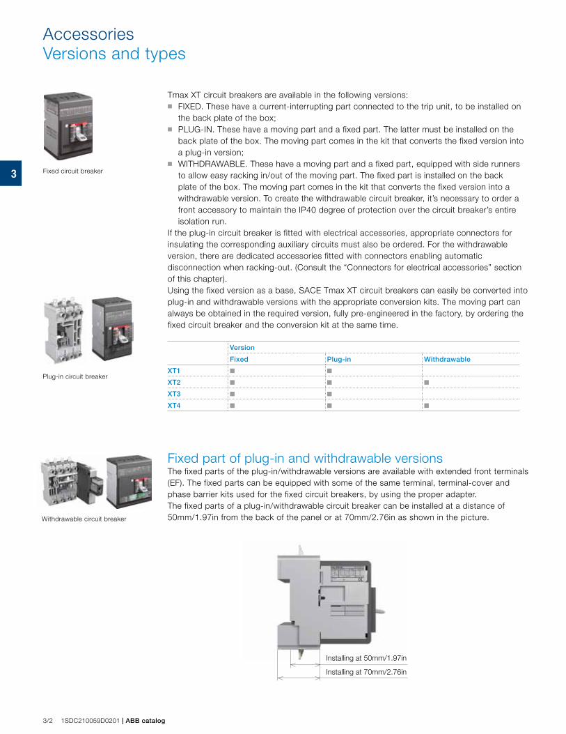
Tmax XT circuit breakers are available in the following versions: ■ FIXED. These have a current-interrupting part connected to the trip unit, to be installed on
the back plate of the box;■ PLUG-IN. These have a moving part and a fixed part. The latter must be installed on the
back plate of the box. The moving part comes in the kit that converts the fixed version into a plug-in version;
■ WITHDRAWABLE. These have a moving part and a fixed part, equipped with side runners to allow easy racking in/out of the moving part. The fixed part is installed on the back plate of the box. The moving part comes in the kit that converts the fixed version into a withdrawable version. To create the withdrawable circuit breaker, it’s necessary to order a front accessory to maintain the IP40 degree of protection over the circuit breaker’s entire isolation run.
If the plug-in circuit breaker is fitted with electrical accessories, appropriate connectors for insulating the corresponding auxiliary circuits must also be ordered. For the withdrawable version, there are dedicated accessories fitted with connectors enabling automatic disconnection when racking-out. (Consult the “Connectors for electrical accessories” section of this chapter).Using the fixed version as a base, SACE Tmax XT circuit breakers can easily be converted into plug-in and withdrawable versions with the appropriate conversion kits. The moving part can always be obtained in the required version, fully pre-engineered in the factory, by ordering the fixed circuit breaker and the conversion kit at the same time.
Version
Fixed Plug-in Withdrawable
XT1 ■ ■
XT2 ■ ■ ■
XT3 ■ ■
XT4 ■ ■ ■
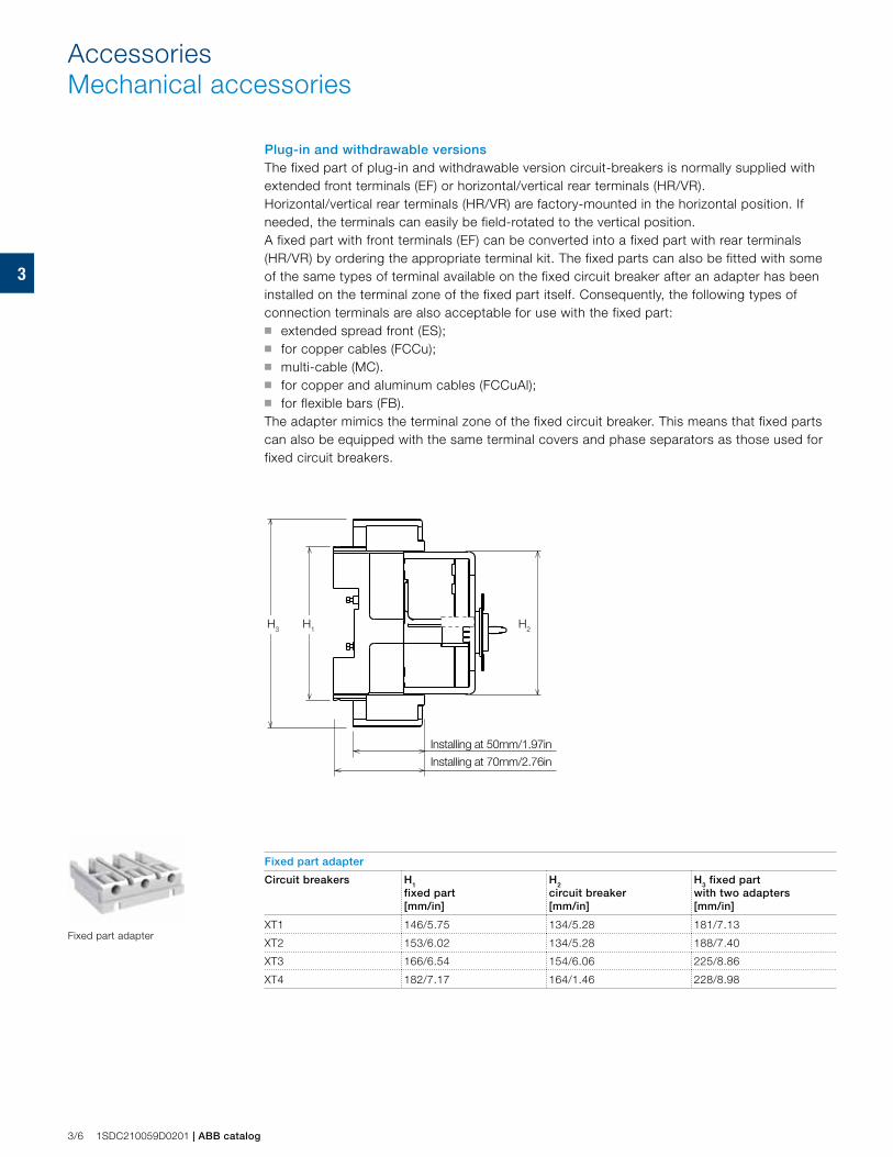
Fixed part of plug-in and withdrawable versionsThe fixed parts of the plug-in/withdrawable versions are available with extended front terminals (EF). The fixed parts can be equipped with some of the same terminal, terminal-cover and phase barrier kits used for the fixed circuit breakers, by using the proper adapter. The fixed parts of a plug-in/withdrawable circuit breaker can be installed at a distance of 50mm/1.97in from the back of the panel or at 70mm/2.76in as shown in the picture.
Fixed circuit breaker
Plug-in circuit breaker
Withdrawable circuit breaker
Installing at 50mm/1.97in
Installing at 70mm/2.76in
3
ABB catalog | 1SDC210059D0201 3/3
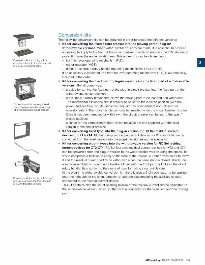
Conversion kitsThe following conversion kits can be obtained in order to create the different versions:■ Kit for converting the fixed circuit breaker into the moving part of plug-in/
withdrawable versions. When withdrawable versions are made, it is essential to order an accessory to apply to the front of the circuit breaker in order to maintain the IP40 degree of protection over the entire isolation run. This accessory can be chosen from: – front for lever operating mechanism (FLD); – motor operator (MOE);– direct or extended rotary handle operating mechanisms (RHD or RHE).
If no accessory is indicated, the front for lever operating mechanism (FLD) is automatically included in the order.
■ Kit for converting the fixed part of plug-in versions into the fixed part of withdrawable versions. The kit comprises: – a guide for turning the fixed part of the plug-in circuit breaker into the fixed part of the
withdrawable circuit breaker;– a racking-out rotary handle that allows the moving part to be inserted and withdrawn.
The mechanism allows the circuit breaker to be set to the isolated position (with the power and auxiliary circuits disconnected) with the compartment door closed, for operator safety. The rotary handle can only be inserted when the circuit breaker is open. Once it has been removed or withdrawn, the circuit breaker can be set to the open/closed position;
– a flange for the compartment door, which replaces the one supplied with the fixed version of the circuit breaker.
■ Kit for converting fixed type into the plug-in version for RC Sel residual current devices for XT2-XT4. RC Sel four-pole residual current devices for XT2 and XT4 can be converted from the fixed version into the plug-in version using the special kit.
■ Kit for converting plug-in types into the withdrawable version for RC Sel residual current devices for XT2-XT4. RC Sel four-pole residual current devices for XT2 and XT4 can be converted from the plug-in version to the withdrawable version using the special kit, which comprises a bellows to apply to the front of the residual current device so as to allow it and the residual current part to be withdrawn when the panel door is closed. This kit can also be assembled on fixed circuit breakers fitted with the front part for locks or the direct rotary handle, thus adding to the range of uses for residual current devices.
In the plug-in to withdrawable conversion kit, there is also a 6-pin connector to be applied onto the right side of the circuit breaker to facilitate disconnecting the auxiliary circuits connected to the residual current device.
This kit contains also the shunt opening release of the residual current device dedicated to the withdrawable version, which is fitted with a connector for the fixed part and the moving part.
Conversion kit for turning a fixed circuit breaker into the moving part of a plug-in circuit breaker
Conversion kit for turning a fixed circuit breaker into the moving part of a withdrawable circuit breaker
Conversion kit for turning a fixed part of plug-in version into the fixed part of a withdrawable version
3+ + =
+ + + =
+ + =+
+
AccessoriesVersions and types
3/4 1SDC210059D0201 | ABB catalog
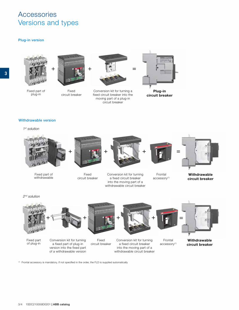
Withdrawable version
1st solution
2nd solution
Fixed part of plug-in
Fixed circuit breaker
Conversion kit for turning a fixed circuit breaker into the
moving part of a plug-in circuit breaker
Plug-in circuit breaker
Fixed part of plug-in
Fixed circuit breaker
Conversion kit for turning a fixed circuit breaker
into the moving part of a withdrawable circuit breaker
Conversion kit for turning a fixed part of plug-in
version into the fixed part of a withdrawable version
Fixed part of withdrawable
Fixed circuit breaker
Conversion kit for turning a fixed circuit breaker
into the moving part of a withdrawable circuit breaker
Withdrawable circuit breaker
Withdrawable circuit breaker
Frontal accessory(1)
Frontal accessory(1)
(1) Frontal accessory is mandatory. If not specified in the order, the FLD is supplied automatically
Plug-in version
3
ABB catalog | 1SDC210059D0201 3/5
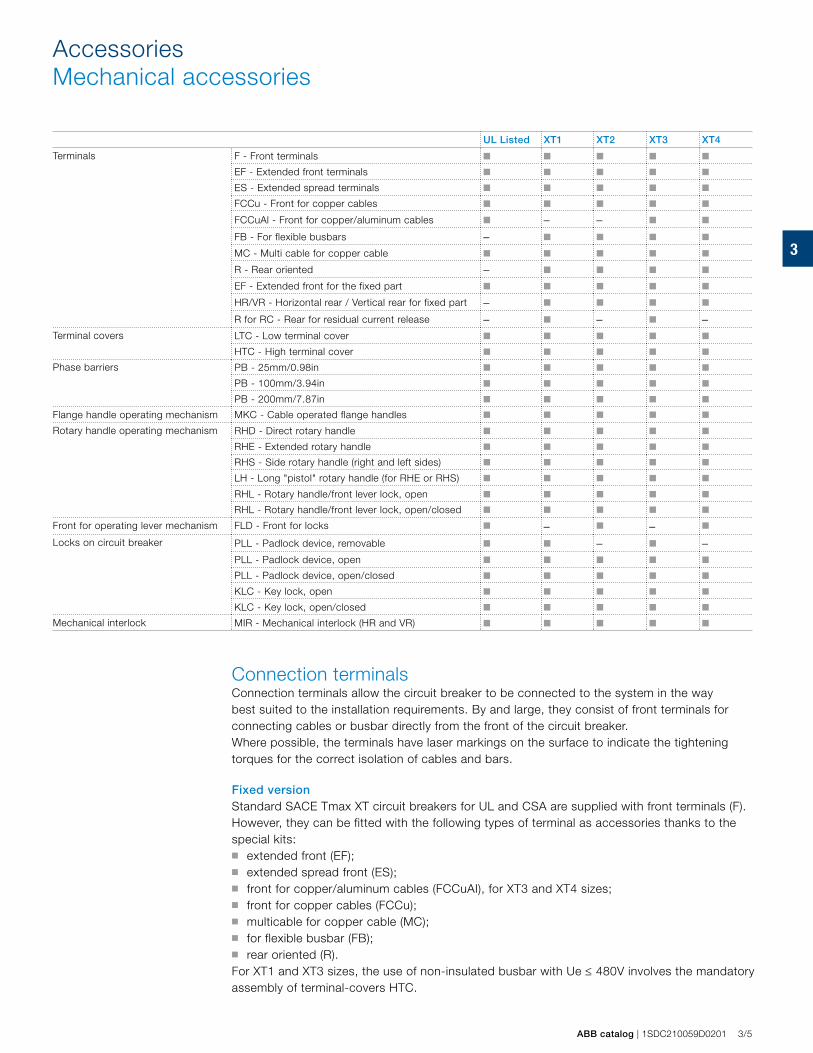
UL Listed XT1 XT2 XT3 XT4
Terminals F - Front terminals ■ ■ ■ ■ ■
EF - Extended front terminals ■ ■ ■ ■ ■
ES - Extended spread terminals ■ ■ ■ ■ ■
FCCu - Front for copper cables ■ ■ ■ ■ ■
FCCuAl - Front for copper/aluminum cables ■ – – ■ ■
FB - For flexible busbars – ■ ■ ■ ■
MC - Multi cable for copper cable ■ ■ ■ ■ ■
R - Rear oriented – ■ ■ ■ ■
EF - Extended front for the fixed part ■ ■ ■ ■ ■
HR/VR - Horizontal rear / Vertical rear for fixed part – ■ ■ ■ ■
R for RC - Rear for residual current release – ■ – ■ –Terminal covers LTC - Low terminal cover ■ ■ ■ ■ ■
HTC - High terminal cover ■ ■ ■ ■ ■
Phase barriers PB - 25mm/0.98in ■ ■ ■ ■ ■
PB - 100mm/3.94in ■ ■ ■ ■ ■
PB - 200mm/7.87in ■ ■ ■ ■ ■
Flange handle operating mechanism MKC - Cable operated flange handles ■ ■ ■ ■ ■
Rotary handle operating mechanism RHD - Direct rotary handle ■ ■ ■ ■ ■
RHE - Extended rotary handle ■ ■ ■ ■ ■
RHS - Side rotary handle (right and left sides) ■ ■ ■ ■ ■
LH - Long "pistol" rotary handle (for RHE or RHS) ■ ■ ■ ■ ■
RHL - Rotary handle/front lever lock, open ■ ■ ■ ■ ■
RHL - Rotary handle/front lever lock, open/closed ■ ■ ■ ■ ■
Front for operating lever mechanism FLD - Front for locks ■ – ■ – ■
Locks on circuit breaker PLL - Padlock device, removable ■ ■ – ■ –PLL - Padlock device, open ■ ■ ■ ■ ■
PLL - Padlock device, open/closed ■ ■ ■ ■ ■
KLC - Key lock, open ■ ■ ■ ■ ■
KLC - Key lock, open/closed ■ ■ ■ ■ ■
Mechanical interlock MIR - Mechanical interlock (HR and VR) ■ ■ ■ ■ ■
AccessoriesMechanical accessories
Connection terminalsConnection terminals allow the circuit breaker to be connected to the system in the way best suited to the installation requirements. By and large, they consist of front terminals for connecting cables or busbar directly from the front of the circuit breaker. Where possible, the terminals have laser markings on the surface to indicate the tightening torques for the correct isolation of cables and bars.
Fixed versionStandard SACE Tmax XT circuit breakers for UL and CSA are supplied with front terminals (F). However, they can be fitted with the following types of terminal as accessories thanks to the special kits:■ extended front (EF);■ extended spread front (ES); ■ front for copper/aluminum cables (FCCuAI), for XT3 and XT4 sizes; ■ front for copper cables (FCCu); ■ multicable for copper cable (MC);■ for flexible busbar (FB);■ rear oriented (R).For XT1 and XT3 sizes, the use of non-insulated busbar with Ue ≤ 480V involves the mandatory assembly of terminal-covers HTC.
3
H3 H1 H2
3/6 1SDC210059D0201 | ABB catalog
Plug-in and withdrawable versions The fixed part of plug-in and withdrawable version circuit-breakers is normally supplied with extended front terminals (EF) or horizontal/vertical rear terminals (HR/VR).Horizontal/vertical rear terminals (HR/VR) are factory-mounted in the horizontal position. If needed, the terminals can easily be field-rotated to the vertical position.A fixed part with front terminals (EF) can be converted into a fixed part with rear terminals (HR/VR) by ordering the appropriate terminal kit. The fixed parts can also be fitted with some of the same types of terminal available on the fixed circuit breaker after an adapter has been installed on the terminal zone of the fixed part itself. Consequently, the following types of connection terminals are also acceptable for use with the fixed part: ■ extended spread front (ES); ■ for copper cables (FCCu); ■ multi-cable (MC).■ for copper and aluminum cables (FCCuAl);■ for flexible bars (FB).The adapter mimics the terminal zone of the fixed circuit breaker. This means that fixed parts can also be equipped with the same terminal covers and phase separators as those used for fixed circuit breakers.
Fixed part adapter
Installing at 50mm/1.97in
Installing at 70mm/2.76in
Fixed part adapter
Circuit breakers H1 fixed part [mm/in]
H2 circuit breaker [mm/in]
H3 fixed part with two adapters [mm/in]
XT1 146/5.75 134/5.28 181/7.13
XT2 153/6.02 134/5.28 188/7.40
XT3 166/6.54 154/6.06 225/8.86
XT4 182/7.17 164/1.46 228/8.98
AccessoriesMechanical accessories
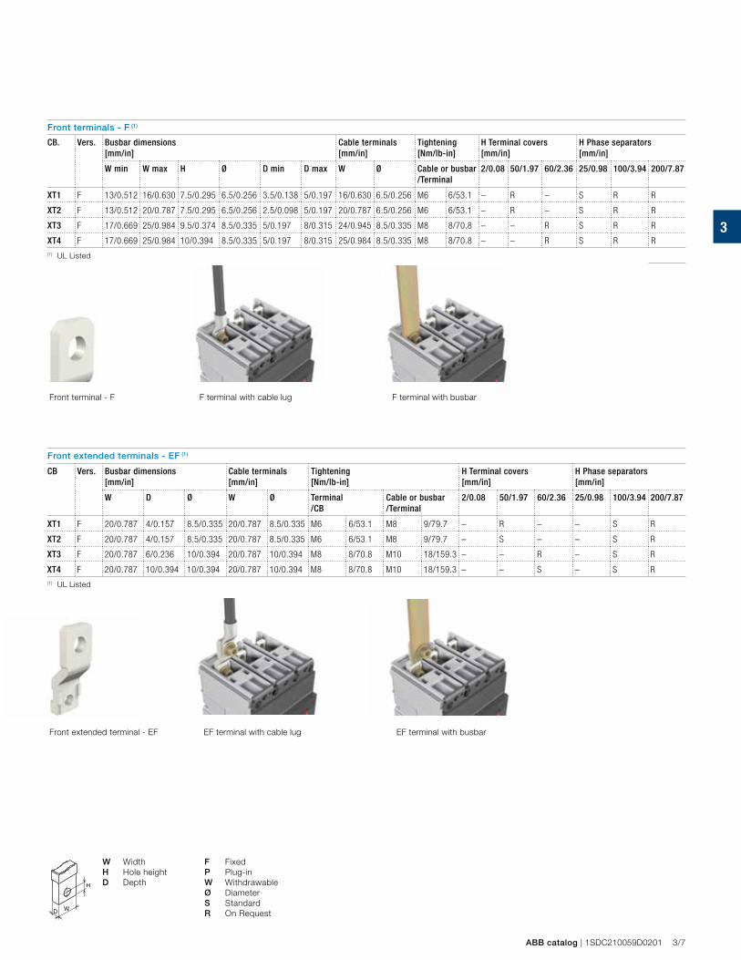
3
ABB catalog | 1SDC210059D0201 3/7
Front terminals - F (1)
CB. Vers. Busbar dimensions[mm/in]
Cable terminals[mm/in]
Tightening[Nm/lb-in]
H Terminal covers [mm/in]
H Phase separators [mm/in]
W min W max H Ø D min D max W Ø Cable or busbar /Terminal
2/0.08 50/1.97 60/2.36 25/0.98 100/3.94 200/7.87
XT1 F 13/0.512 16/0.630 7.5/0.295 6.5/0.256 3.5/0.138 5/0.197 16/0.630 6.5/0.256 M6 6/53.1 – R – S R R
XT2 F 13/0.512 20/0.787 7.5/0.295 6.5/0.256 2.5/0.098 5/0.197 20/0.787 6.5/0.256 M6 6/53.1 – R – S R R
XT3 F 17/0.669 25/0.984 9.5/0.374 8.5/0.335 5/0.197 8/0.315 24/0.945 8.5/0.335 M8 8/70.8 – – R S R R
XT4 F 17/0.669 25/0.984 10/0.394 8.5/0.335 5/0.197 8/0.315 25/0.984 8.5/0.335 M8 8/70.8 – – R S R R(1) UL Listed
Front extended terminals - EF (1)
CB Vers. Busbar dimensions[mm/in]
Cable terminals[mm/in]
Tightening[Nm/lb-in]
H Terminal covers [mm/in]
H Phase separators [mm/in]
W D Ø W Ø Terminal/CB
Cable or busbar /Terminal
2/0.08 50/1.97 60/2.36 25/0.98 100/3.94 200/7.87
XT1 F 20/0.787 4/0.157 8.5/0.335 20/0.787 8.5/0.335 M6 6/53.1 M8 9/79.7 – R – – S R
XT2 F 20/0.787 4/0.157 8.5/0.335 20/0.787 8.5/0.335 M6 6/53.1 M8 9/79.7 – S – – S R
XT3 F 20/0.787 6/0.236 10/0.394 20/0.787 10/0.394 M8 8/70.8 M10 18/159.3 – – R – S R
XT4 F 20/0.787 10/0.394 10/0.394 20/0.787 10/0.394 M8 8/70.8 M10 18/159.3 – – S – S R(1) UL Listed
W Width F Fixed H Hole height P Plug-inD Depth W Withdrawable
Ø DiameterS StandardR On Request
F terminal with cable lug F terminal with busbarFront terminal - F
Front extended terminal - EF EF terminal with cable lug EF terminal with busbar
D W
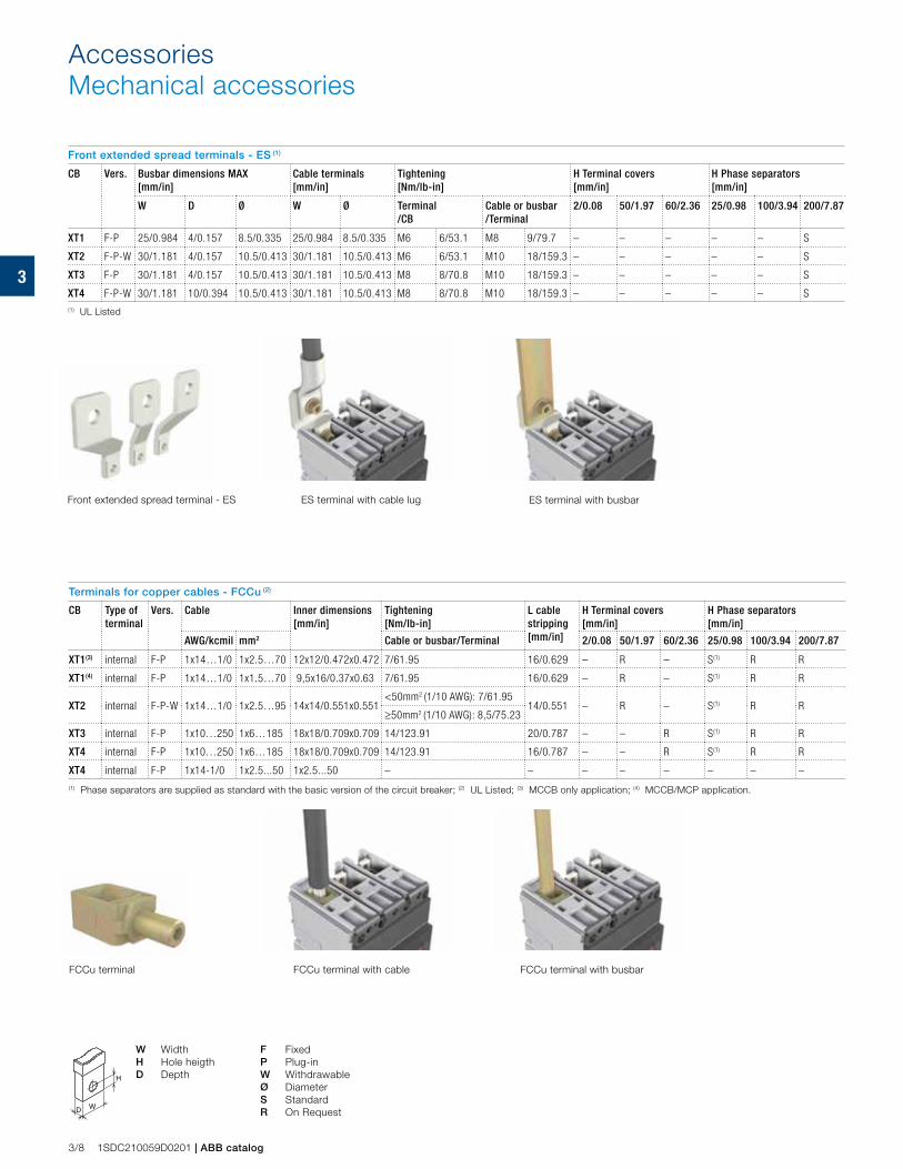
3
3/8 1SDC210059D0201 | ABB catalog
Front extended spread terminals - ES (1)
CB Vers. Busbar dimensions MAX[mm/in]
Cable terminals[mm/in]
Tightening[Nm/lb-in]
H Terminal covers [mm/in]
H Phase separators [mm/in]
W D Ø W Ø Terminal/CB
Cable or busbar /Terminal
2/0.08 50/1.97 60/2.36 25/0.98 100/3.94 200/7.87
XT1 F-P 25/0.984 4/0.157 8.5/0.335 25/0.984 8.5/0.335 M6 6/53.1 M8 9/79.7 – – – – – S
XT2 F-P-W 30/1.181 4/0.157 10.5/0.413 30/1.181 10.5/0.413 M6 6/53.1 M10 18/159.3 – – – – – S
XT3 F-P 30/1.181 4/0.157 10.5/0.413 30/1.181 10.5/0.413 M8 8/70.8 M10 18/159.3 – – – – – S
XT4 F-P-W 30/1.181 10/0.394 10.5/0.413 30/1.181 10.5/0.413 M8 8/70.8 M10 18/159.3 – – – – – S(1) UL Listed
Terminals for copper cables - FCCu (2)
CB Type of terminal
Vers. Cable Inner dimensions[mm/in]
Tightening [Nm/lb-in]
L cable stripping[mm/in]
H Terminal covers [mm/in]
H Phase separators [mm/in]
AWG/kcmil mm2 Cable or busbar/Terminal 2/0.08 50/1.97 60/2.36 25/0.98 100/3.94 200/7.87
XT1(3) internal F-P 1x14…1/0 1x2.5…70 12x12/0.472x0.472 7/61.95 16/0.629 – R – S(1) R R
XT1(4) internal F-P 1x14…1/0 1x1.5…70 9,5x16/0.37x0.63 7/61.95 16/0.629 – R – S(1) R R
XT2 internal F-P-W 1x14…1/0 1x2.5…95 14x14/0.551x0.551<50mm2 (1/10 AWG): 7/61.95
14/0.551 – R – S(1) R R≥50mm2 (1/10 AWG): 8,5/75.23
XT3 internal F-P 1x10…250 1x6…185 18x18/0.709x0.709 14/123.91 20/0.787 – – R S(1) R R
XT4 internal F-P 1x10…250 1x6…185 18x18/0.709x0.709 14/123.91 16/0.787 – – R S(1) R R
XT4 internal F-P 1x14-1/0 1x2.5...50 1x2.5...50 – – – – – – – –
(1) Phase separators are supplied as standard with the basic version of the circuit breaker; (2) UL Listed; (3) MCCB only application; (4) MCCB/MCP application.
Front extended spread terminal - ES ES terminal with cable lug ES terminal with busbar
FCCu terminal FCCu terminal with cable FCCu terminal with busbar
W Width F Fixed H Hole heigth P Plug-inD Depth W Withdrawable
Ø DiameterS StandardR On RequestD W
AccessoriesMechanical accessories
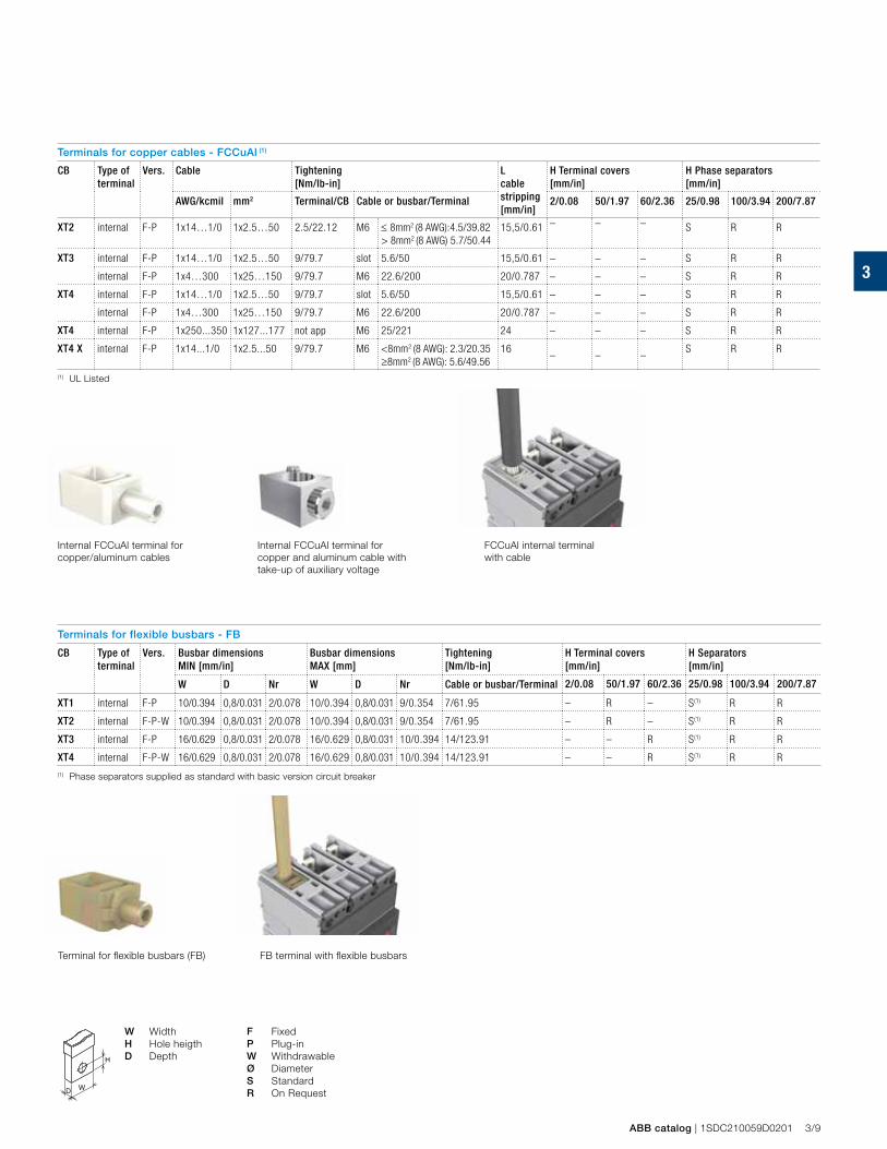
3
ABB catalog | 1SDC210059D0201 3/9
Terminals for copper cables - FCCuAl (1)
CB Type of terminal
Vers. Cable Tightening[Nm/lb-in]
L cable stripping[mm/in]
H Terminal covers [mm/in]
H Phase separators [mm/in]
AWG/kcmil mm2 Terminal/CB Cable or busbar/Terminal 2/0.08 50/1.97 60/2.36 25/0.98 100/3.94 200/7.87
XT2 internal F-P 1x14…1/0 1x2.5…50 2.5/22.12 M6 ≤ 8mm2 (8 AWG):4.5/39.82> 8mm2 (8 AWG) 5.7/50.44
15,5/0.61 – – – S R R
XT3 internal F-P 1x14…1/0 1x2.5…50 9/79.7 slot 5.6/50 15,5/0.61 – – – S R R
internal F-P 1x4…300 1x25…150 9/79.7 M6 22.6/200 20/0.787 – – – S R R
XT4 internal F-P 1x14…1/0 1x2.5…50 9/79.7 slot 5.6/50 15,5/0.61 – – – S R R
internal F-P 1x4…300 1x25…150 9/79.7 M6 22.6/200 20/0.787 – – – S R R
XT4 internal F-P 1x250...350 1x127...177 not app M6 25/221 24 – – – S R R
XT4 X internal F-P 1x14...1/0 1x2.5...50 9/79.7 M6 <8mm2 (8 AWG): 2.3/20.35≥8mm2 (8 AWG): 5.6/49.56
16– – –
S R R
(1) UL Listed
Internal FCCuAl terminal for copper/aluminum cables
FCCuAl internal terminal with cable
W Width F Fixed H Hole heigth P Plug-inD Depth W Withdrawable
Ø DiameterS StandardR On RequestD W
Internal FCCuAl terminal for copper and aluminum cable with take-up of auxiliary voltage
Terminals for flexible busbars - FB
CB Type of terminal
Vers. Busbar dimensions MIN [mm/in]
Busbar dimensionsMAX [mm]
Tightening[Nm/lb-in]
H Terminal covers [mm/in]
H Separators[mm/in]
W D Nr W D Nr Cable or busbar/Terminal 2/0.08 50/1.97 60/2.36 25/0.98 100/3.94 200/7.87
XT1 internal F-P 10/0.394 0,8/0.031 2/0.078 10/0.394 0,8/0.031 9/0.354 7/61.95 – R – S(1) R R
XT2 internal F-P-W 10/0.394 0,8/0.031 2/0.078 10/0.394 0,8/0.031 9/0.354 7/61.95 – R – S(1) R R
XT3 internal F-P 16/0.629 0,8/0.031 2/0.078 16/0.629 0,8/0.031 10/0.394 14/123.91 – – R S(1) R R
XT4 internal F-P-W 16/0.629 0,8/0.031 2/0.078 16/0.629 0,8/0.031 10/0.394 14/123.91 – – R S(1) R R
(1) Phase separators supplied as standard with basic version circuit breaker
Terminal for flexible busbars (FB) FB terminal with flexible busbars
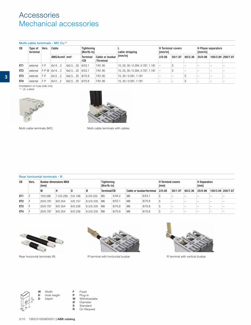
3
3/10 1SDC210059D0201 | ABB catalog
AccessoriesMechanical accessories
Multi-cable terminals - MC Cu (1)
CB Type of terminal
Vers. Cable Tightening[Nm/lb-in]
L cable stripping[mm/in]
H Terminal covers [mm/in]
H Phase separators [mm/in]
AWG/kcmil mm2 Terminal/CB
Cable or busbar /Terminal
2/0.08 50/1.97 60/2.36 25/0.98 100/3.94 200/7.87
XT1 external F-P 6x14…2 6x2.5…35 6/53.1 7/61.95 10, 20, 30 / 0.394, 0.787, 1.181 – S – – – –
XT2 external F-P-W 6x14…2 6x2.5…35 6/53.1 7/61.95 10, 20, 30 / 0.394, 0.787, 1.181 – S – – – –
XT3 external F-P 6x12…2 6x2.5…35 8/70.8 7/61.95 15, 30 / 0.591, 1.181 – – S – – –
XT4 external F-P 6x12…2 6x2.5…35 8/70.8 7/61.95 15, 30 / 0.591, 1.181 – – S – – –
Installation on loas side only (1) UL Listed
Multi-cable terminals with cablesMulti-cable terminals (MC)
W Width F Fixed H Hole heigth P Plug-inD Depth W Withdrawable
Ø DiameterS StandardR On RequestD W
Rear horizontal terminals (R) R terminal with horizontal busbar R terminal with vertical busbar
Rear horizontal terminals - R
CB Vers. Busbar dimensions MAX [mm]
Tightening[Nm/lb-in]
H Terminal covers [mm]
H Separators[mm]
W H D Ø Terminal/CB Cable or busbar/terminal 2/0.08 50/1.97 60/2.36 25/0.98 100/3.94 200/7.87
XT1 F 15/0.590 7.5/0.295 5/0.196 6.5/0.255 M5 5/44.2 M6 6/53.1 S – – – – –
XT2 F 20/0.787 9/0.354 4/0.157 8.5/0.335 M6 6/53.1 M8 8/70.8 S – – – – –
XT3 F 20/0.787 9/0.354 6/0.236 8.5/0.335 M8 8/70.8 M8 8/70.8 S – – – – –
XT4 F 20/0.787 9/0.354 6/0.236 8.5/0.335 M8 8/70.8 M8 8/70.8 S – – – – –
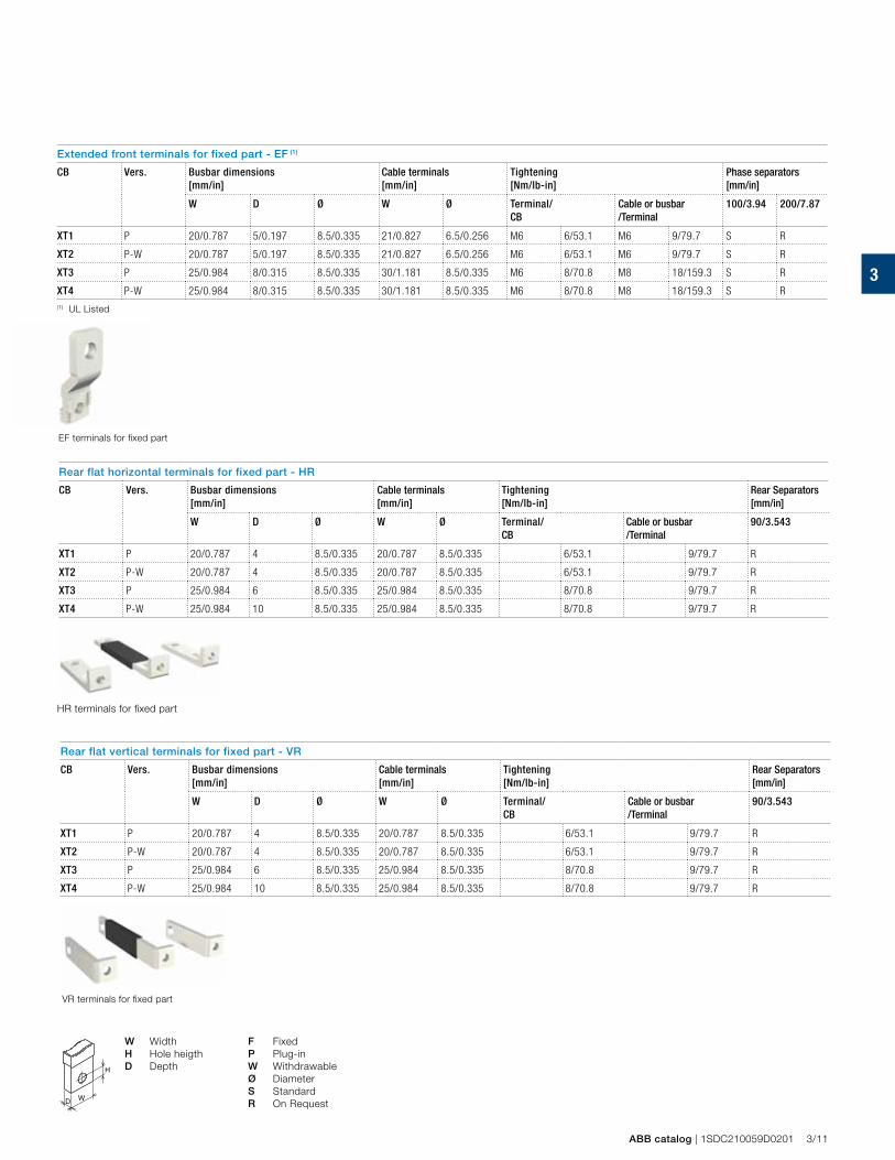
3
ABB catalog | 1SDC210059D0201 3/11
Extended front terminals for fixed part - EF (1)
CB Vers. Busbar dimensions[mm/in]
Cable terminals[mm/in]
Tightening [Nm/lb-in]
Phase separators [mm/in]
W D Ø W Ø Terminal/CB
Cable or busbar /Terminal
100/3.94 200/7.87
XT1 P 20/0.787 5/0.197 8.5/0.335 21/0.827 6.5/0.256 M6 6/53.1 M6 9/79.7 S R
XT2 P-W 20/0.787 5/0.197 8.5/0.335 21/0.827 6.5/0.256 M6 6/53.1 M6 9/79.7 S R
XT3 P 25/0.984 8/0.315 8.5/0.335 30/1.181 8.5/0.335 M6 8/70.8 M8 18/159.3 S R
XT4 P-W 25/0.984 8/0.315 8.5/0.335 30/1.181 8.5/0.335 M6 8/70.8 M8 18/159.3 S R(1) UL Listed
W Width F Fixed H Hole heigth P Plug-inD Depth W Withdrawable
Ø DiameterS StandardR On RequestD W
EF terminals for fixed part
Rear flat horizontal terminals for fixed part - HR
CB Vers. Busbar dimensions[mm/in]
Cable terminals[mm/in]
Tightening [Nm/lb-in]
Rear Separators[mm/in]
W D Ø W Ø Terminal/CB
Cable or busbar /Terminal
90/3.543
XT1 P 20/0.787 4 8.5/0.335 20/0.787 8.5/0.335 6/53.1 9/79.7 R
XT2 P-W 20/0.787 4 8.5/0.335 20/0.787 8.5/0.335 6/53.1 9/79.7 R
XT3 P 25/0.984 6 8.5/0.335 25/0.984 8.5/0.335 8/70.8 9/79.7 R
XT4 P-W 25/0.984 10 8.5/0.335 25/0.984 8.5/0.335 8/70.8 9/79.7 R
HR terminals for fixed part
VR terminals for fixed part
Rear flat vertical terminals for fixed part - VR
CB Vers. Busbar dimensions[mm/in]
Cable terminals[mm/in]
Tightening [Nm/lb-in]
Rear Separators[mm/in]
W D Ø W Ø Terminal/CB
Cable or busbar /Terminal
90/3.543
XT1 P 20/0.787 4 8.5/0.335 20/0.787 8.5/0.335 6/53.1 9/79.7 R
XT2 P-W 20/0.787 4 8.5/0.335 20/0.787 8.5/0.335 6/53.1 9/79.7 R
XT3 P 25/0.984 6 8.5/0.335 25/0.984 8.5/0.335 8/70.8 9/79.7 R
XT4 P-W 25/0.984 10 8.5/0.335 25/0.984 8.5/0.335 8/70.8 9/79.7 R
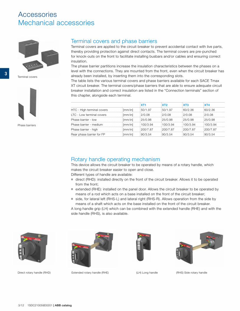
3
3/12 1SDC210059D0201 | ABB catalog
Terminal covers and phase barriersTerminal covers are applied to the circuit breaker to prevent accidental contact with live parts, thereby providing protection against direct contacts. The terminal covers are pre-punched for knock-outs on the front to facilitate installing busbars and/or cables and ensuring correct insulation.The phase barrier partitions increase the insulation characteristics between the phases on a level with the connections. They are mounted from the front, even when the circuit breaker has already been installed, by inserting them into the corresponding slots. The table lists the various terminal covers and phase barriers available for each SACE Tmax XT circuit breaker. The terminal covers/phase barriers that are able to ensure adequate circuit breaker installation and correct insulation are listed in the “Connection terminals” section of this chapter, alongside each terminal.
XT1 XT2 XT3 XT4
HTC - High terminal covers [mm/in] 50/1.97 50/1.97 60/2.36 60/2.36
LTC - Low terminal covers [mm/in] 2/0.08 2/0.08 2/0.08 2/0.08
Phase barrier - low [mm/in] 25/0.98 25/0.98 25/0.98 25/0.98
Phase barrier - medium [mm/in] 100/3.94 100/3.94 100/3.94 100/3.94
Phase barrier - high [mm/in] 200/7.87 200/7.87 200/7.87 200/7.87
Rear phase barrier for FP [mm/in] 90/3.54 90/3.54 90/3.54 90/3.54
Rotary handle operating mechanismThis device allows the circuit breaker to be operated by means of a rotary handle, which makes the circuit breaker easier to open and close. Different types of handle are available: ■ direct (RHD): installed directly on the front of the circuit breaker. Allows it to be operated
from the front; ■ extended (RHE): installed on the panel door. Allows the circuit breaker to be operated by
means of a rod which acts on a base installed on the front of the circuit breaker;■ side, for lateral left (RHS-L) and lateral right (RHS-R). Allows operation from the side by
means of a shaft which acts on the base installed on the front of the circuit breaker.A long handle grip (LH) which can be combined with the extended handle (RHE) and with the side handle (RHS), is also available.
Terminal covers
Phase barriers
Direct rotary handle (RHD) Extended rotary handle (RHE) (LH) Long handle (RHS) Side rotary handle
AccessoriesMechanical accessories
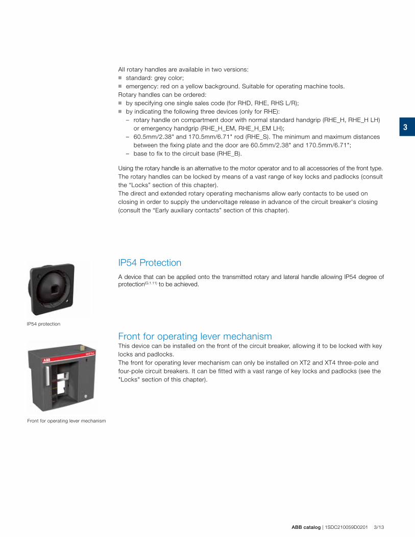
3
ABB catalog | 1SDC210059D0201 3/13
All rotary handles are available in two versions: ■ standard: grey color; ■ emergency: red on a yellow background. Suitable for operating machine tools. Rotary handles can be ordered: ■ by specifying one single sales code (for RHD, RHE, RHS L/R);■ by indicating the following three devices (only for RHE):
– rotary handle on compartment door with normal standard handgrip (RHE_H, RHE_H LH) or emergency handgrip (RHE_H_EM, RHE_H_EM LH);
– 60.5mm/2.38" and 170.5mm/6.71" rod (RHE_S). The minimum and maximum distances between the fixing plate and the door are 60.5mm/2.38" and 170.5mm/6.71";
– base to fix to the circuit base (RHE_B).
Using the rotary handle is an alternative to the motor operator and to all accessories of the front type. The rotary handles can be locked by means of a vast range of key locks and padlocks (consult the “Locks” section of this chapter).The direct and extended rotary operating mechanisms allow early contacts to be used on closing in order to supply the undervoltage release in advance of the circuit breaker's closing (consult the “Early auxiliary contacts” section of this chapter).
IP54 ProtectionA device that can be applied onto the transmitted rotary and lateral handle allowing IP54 degree of protection(G.1.11) to be achieved.
Front for operating lever mechanismThis device can be installed on the front of the circuit breaker, allowing it to be locked with key locks and padlocks. The front for operating lever mechanism can only be installed on XT2 and XT4 three-pole and four-pole circuit breakers. It can be fitted with a vast range of key locks and padlocks (see the "Locks" section of this chapter).
Front for operating lever mechanism
IP54 protection
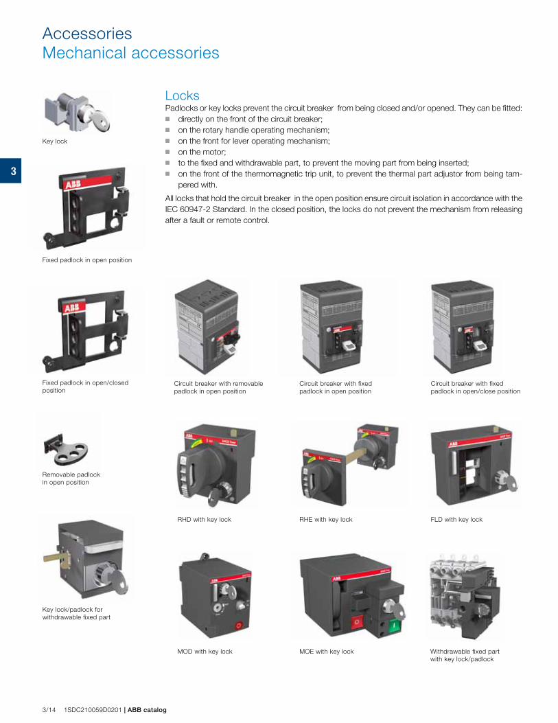
3
3/14 1SDC210059D0201 | ABB catalog
Locks Padlocks or key locks prevent the circuit breaker from being closed and/or opened. They can be fitted: ■ directly on the front of the circuit breaker; ■ on the rotary handle operating mechanism;■ on the front for lever operating mechanism; ■ on the motor; ■ to the fixed and withdrawable part, to prevent the moving part from being inserted;■ on the front of the thermomagnetic trip unit, to prevent the thermal part adjustor from being tam-
pered with.
All locks that hold the circuit breaker in the open position ensure circuit isolation in accordance with the IEC 60947-2 Standard. In the closed position, the locks do not prevent the mechanism from releasing after a fault or remote control.
AccessoriesMechanical accessories
Key lock
Fixed padlock in open position
Fixed padlock in open/closed position
Removable padlock in open position
Key lock/padlock for withdrawable fixed part
Circuit breaker with removable padlock in open position
Circuit breaker with fixed padlock in open position
Circuit breaker with fixed padlock in open/close position
RHD with key lock RHE with key lock FLD with key lock
MOD with key lock MOE with key lock Withdrawable fixed part with key lock/padlock
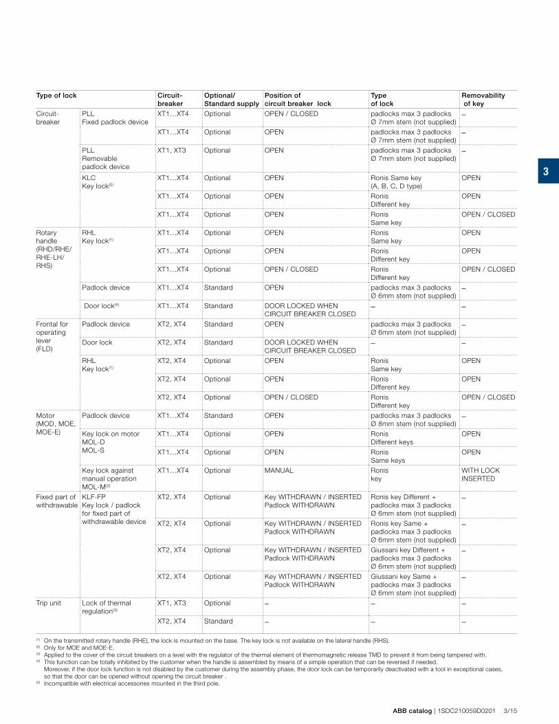
3
ABB catalog | 1SDC210059D0201 3/15
Type of lock Circuit-breaker
Optional/Standard supply
Position of circuit breaker lock
Type of lock
Removability of key
Circuit-breaker
PLL Fixed padlock device
XT1…XT4 Optional OPEN / CLOSED padlocks max 3 padlocks Ø 7mm stem (not supplied)
–
XT1…XT4 Optional OPEN padlocks max 3 padlocks Ø 7mm stem (not supplied)
–
PLL Removable padlock device
XT1, XT3 Optional OPEN padlocks max 3 padlocks Ø 7mm stem (not supplied)
–
KLC Key lock(5)
XT1…XT4 Optional OPEN Ronis Same key (A, B, C, D type)
OPEN
XT1…XT4 Optional OPEN Ronis Different key
OPEN
XT1…XT4 Optional OPEN Ronis Same key
OPEN / CLOSED
Rotary handle (RHD/RHE/RHE-LH/RHS)
RHL Key lock(1)
XT1…XT4 Optional OPEN Ronis Same key
OPEN
XT1…XT4 Optional OPEN Ronis Different key
OPEN
XT1…XT4 Optional OPEN / CLOSED Ronis Different key
OPEN / CLOSED
Padlock device XT1…XT4 Standard OPEN padlocks max 3 padlocks Ø 6mm stem (not supplied)
–
Door lock(4) XT1…XT4 Standard DOOR LOCKED WHEN CIRCUIT BREAKER CLOSED
– –
Frontal for operating lever (FLD)
Padlock device XT2, XT4 Standard OPEN padlocks max 3 padlocks Ø 6mm stem (not supplied)
–
Door lock XT2, XT4 Standard DOOR LOCKED WHEN CIRCUIT BREAKER CLOSED
– –
RHL Key lock(1)
XT2, XT4 Optional OPEN Ronis Same key
OPEN
XT2, XT4 Optional OPEN Ronis Different key
OPEN
XT2, XT4 Optional OPEN / CLOSED Ronis Different key
OPEN / CLOSED
Motor (MOD, MOE, MOE-E)
Padlock device XT1…XT4 Standard OPEN padlocks max 3 padlocks Ø 8mm stem (not supplied)
–
Key lock on motor MOL-D MOL-S
XT1…XT4 Optional OPEN Ronis Different keys
OPEN
XT1…XT4 Optional OPEN Ronis Same keys
OPEN
Key lock against manual operation MOL-M(2)
XT1…XT4 Optional MANUAL Ronis key
WITH LOCK INSERTED
Fixed part of withdrawable
KLF-FP Key lock / padlock for fixed part of withdrawable device
XT2, XT4 Optional Key WITHDRAWN / INSERTEDPadlock WITHDRAWN
Ronis key Different + padlocks max 3 padlocks Ø 6mm stem (not supplied)
–
XT2, XT4 Optional Key WITHDRAWN / INSERTEDPadlock WITHDRAWN
Ronis key Same + padlocks max 3 padlocks Ø 6mm stem (not supplied)
–
XT2, XT4 Optional Key WITHDRAWN / INSERTEDPadlock WITHDRAWN
Giussani key Different + padlocks max 3 padlocks Ø 6mm stem (not supplied)
–
XT2, XT4 Optional Key WITHDRAWN / INSERTEDPadlock WITHDRAWN
Giussani key Same + padlocks max 3 padlocks Ø 6mm stem (not supplied)
–
Trip unit Lock of thermal regulation(3)
XT1, XT3 Optional – – –
XT2, XT4 Standard – – –
(1) On the transmitted rotary handle (RHE), the lock is mounted on the base. The key lock is not available on the lateral handle (RHS). (2) Only for MOE and MOE-E. (3) Applied to the cover of the circuit breakers on a level with the regulator of the thermal element of thermomagnetic release TMD to prevent it from being tampered with.(4) This function can be totally inhibited by the customer when the handle is assembled by means of a simple operation that can be reversed if needed. Moreover, if the door lock function is not disabled by the customer during the assembly phase, the door lock can be temporarily deactivated with a tool in exceptional cases,
so that the door can be opened without opening the circuit breaker . (5) Incompatible with electrical accessories mounted in the third pole.
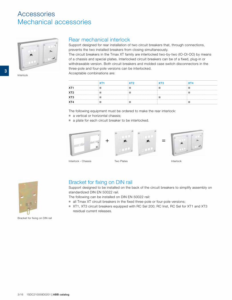
3
+ =
3/16 1SDC210059D0201 | ABB catalog
AccessoriesMechanical accessories
Rear mechanical interlock Support designed for rear installation of two circuit breakers that, through connections, prevents the two installed breakers from closing simultaneously.The circuit breakers in the Tmax XT family are interlocked two-by-two (IO-OI-OO) by means of a chassis and special plates. Interlocked circuit breakers can be of a fixed, plug-in or withdrawable version. Both circuit breakers and molded case switch disconnectors in the three-pole and four-pole versions can be interlocked. Acceptable combinations are:
XT1 XT2 XT3 XT4
XT1 ■ ■ ■ ■
XT2 ■ ■ ■
XT3 ■ ■
XT4 ■ ■ ■
The following equipment must be ordered to make the rear interlock: ■ a vertical or horizontal chassis; ■ a plate for each circuit breaker to be interlocked.
Interlock - Chassis Two Plates Interlock
Interlock
Bracket for fixing on DIN rail
Bracket for fixing on DIN railSupport designed to be installed on the back of the circuit breakers to simplify assembly on standardized DIN EN 50022 rail.The following can be installed on DIN EN 50022 rail: ■ all Tmax XT circuit breakers in the fixed three-pole or four-pole versions; ■ XT1, XT3 circuit breakers equipped with RC Sel 200; RC Inst, RC Sel for XT1 and XT3
residual current releases.
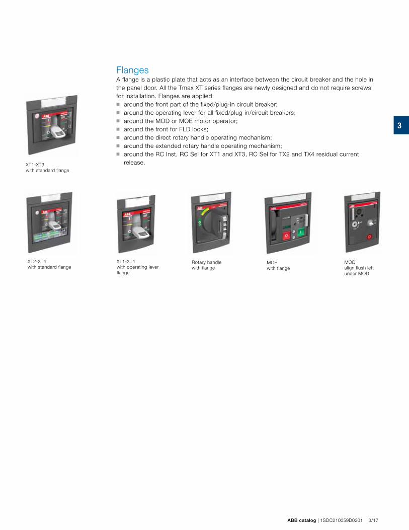
3
ABB catalog | 1SDC210059D0201 3/17
XT1-XT3 with standard flange
XT1-XT4 with operating lever flange
Rotary handle with flange
MOE with flange
MODalign flush left under MOD
XT2-XT4with standard flange
Flanges A flange is a plastic plate that acts as an interface between the circuit breaker and the hole in the panel door. All the Tmax XT series flanges are newly designed and do not require screws for installation. Flanges are applied: ■ around the front part of the fixed/plug-in circuit breaker;■ around the operating lever for all fixed/plug-in/circuit breakers;■ around the MOD or MOE motor operator;■ around the front for FLD locks;■ around the direct rotary handle operating mechanism;■ around the extended rotary handle operating mechanism;■ around the RC Inst, RC Sel for XT1 and XT3, RC Sel for TX2 and TX4 residual current
release.
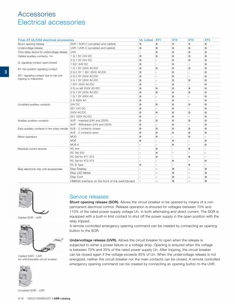
3
3/18 1SDC210059D0201 | ABB catalog
AccessoriesElectrical accessories
Tmax XT UL/CSA electrical accessories UL Listed XT1 XT2 XT3 XT4Shunt opening release SOR / SOR-C (uncabled and cabled) ■ ■ ■ ■ ■
Undervoltage release UVR / UVR-C (uncabled and cabled) ■ ■ ■ ■ ■
Time-delay device for undervoltage release UVD – ■ ■ ■ ■
Cabled auxiliary contacts, 1m
Q: signaling contact open/closed
SY: trip position signaling contact
S51: signaling contact due to trip unit tripping or interaction
1 Q 1 SY 24V DC ■ ■ ■ ■ ■
3 Q 1 SY 24V DC ■ – ■ ■ ■
1 S51 24V DC ■ – ■ – ■
1 Q 1 SY 250V AC/DC ■ ■ ■ ■ ■
2 Q 2 SY 1 S51 250V AC/DC ■ – ■ – ■
3 Q 2 SY 250V AC/DC ■ – ■ – ■
3 Q 1 SY 250V AC/DC ■ – ■ ■ ■
1 S51 250V AC/DC ■ – ■ – ■
3 Q on left 250V AC/DC ■ ■ ■ ■ ■
2 Q 1 SY 250V AC/DC ■ ■ ■ ■ ■
1 Q 1 SY 400V AC ■ – ■ – ■
2 Q 400V AC ■ – ■ – ■
Uncabled auxiliary contacts 24V DC ■ ■ ■ ■ ■
S51 24V DC ■ – ■ – ■
250V AC/DC ■ ■ ■ ■ ■
S51 250V AC/DC ■ – ■ – ■
Auxiliary position contacts AUP - Inserted (24V and 250V) ■ ■ ■ ■ ■
AUP - Withdrawn (24V and 250V) ■ – ■ – ■
Early auxiliary contacts in the rotary handle AUE - 2 contacts closed ■ ■ ■ ■ ■
AUE - 2 contacts open ■ ■ ■ ■ ■
Motor operators MOD ■ ■ – ■ –
MOE ■ – ■ – ■
MOE-E – – ■ – ■
Residual current devices RC Inst – ■ – ■ –
RC Sel 200 – ■ – – –
RC Sel for XT1 XT3 – ■ – ■ –
RC Sel for XT2 XT4 – – ■ – ■
RC B Type ■ – – ■ –
Ekip electronic trip unit accessories Ekip Display – – ■ – ■
Ekip LED Meter – – ■ – ■
Ekip Com – – ■ – ■
HMI030 interface on the front of the switchboard – – ■ – ■
Cabled SOR - UVR
Cabled SOR - UVR for withdrawable circuit breaker
Uncabled SOR - UVR
Service releasesShunt opening release (SOR). Allows the circuit breaker to be opened by means of a non-permanent electrical control. Release operation is ensured for voltages between 70% and 110% of the rated power supply voltage Un, in both alternating and direct current. The SOR is equipped with a built-in limit contact to shut off the power supply in the open position with the relay tripped. A remote controlled emergency opening command can be created by connecting an opening button to the SOR.
Undervoltage release (UVR). Allows the circuit breaker to open when the release is subjected to either a power failure or a voltage drop. Opening is ensured when the voltage is between 70% and 35% of the rated power supply Un. After tripping, the circuit breaker can be closed again if the voltage exceeds 85% of Un. When the undervoltage release is not energized, neither the circuit breaker nor the main contacts can be closed. A remote controlled emergency opening command can be created by connecting an opening button to the UVR.
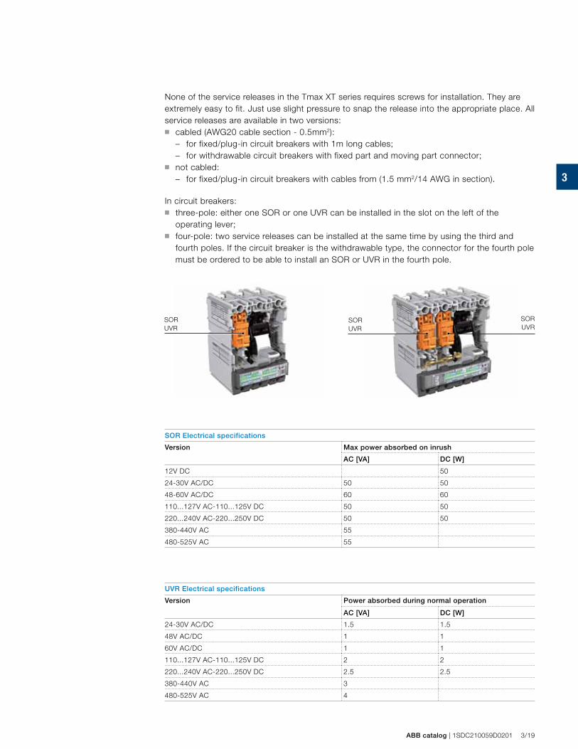
3
SORUVR
SORUVR
SORUVR
ABB catalog | 1SDC210059D0201 3/19
None of the service releases in the Tmax XT series requires screws for installation. They are extremely easy to fit. Just use slight pressure to snap the release into the appropriate place. All service releases are available in two versions: ■ cabled (AWG20 cable section - 0.5mm2):
– for fixed/plug-in circuit breakers with 1m long cables;– for withdrawable circuit breakers with fixed part and moving part connector;
■ not cabled: – for fixed/plug-in circuit breakers with cables from (1.5 mm2/14 AWG in section).
In circuit breakers: ■ three-pole: either one SOR or one UVR can be installed in the slot on the left of the
operating lever; ■ four-pole: two service releases can be installed at the same time by using the third and
fourth poles. If the circuit breaker is the withdrawable type, the connector for the fourth pole must be ordered to be able to install an SOR or UVR in the fourth pole.
SOR Electrical specifications
Version Max power absorbed on inrush
AC [VA] DC [W]
12V DC 50
24-30V AC/DC 50 50
48-60V AC/DC 60 60
110...127V AC-110...125V DC 50 50
220...240V AC-220...250V DC 50 50
380-440V AC 55
480-525V AC 55
UVR Electrical specifications
Version Power absorbed during normal operation
AC [VA] DC [W]
24-30V AC/DC 1.5 1.5
48V AC/DC 1 1
60V AC/DC 1 1
110...127V AC-110...125V DC 2 2
220...240V AC-220...250V DC 2.5 2.5
380-440V AC 3
480-525V AC 4
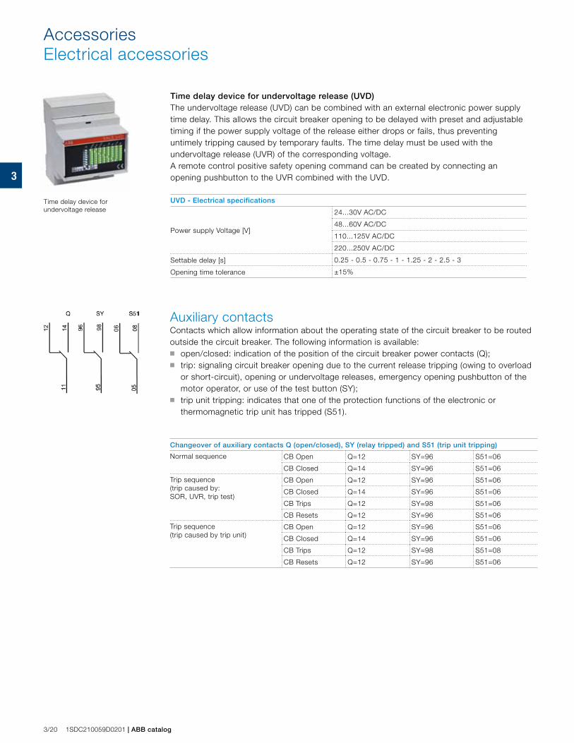
3
3/20 1SDC210059D0201 | ABB catalog
Auxiliary contactsContacts which allow information about the operating state of the circuit breaker to be routed outside the circuit breaker. The following information is available:■ open/closed: indication of the position of the circuit breaker power contacts (Q);■ trip: signaling circuit breaker opening due to the current release tripping (owing to overload
or short-circuit), opening or undervoltage releases, emergency opening pushbutton of the motor operator, or use of the test button (SY);
■ trip unit tripping: indicates that one of the protection functions of the electronic or thermomagnetic trip unit has tripped (S51).
Changeover of auxiliary contacts Q (open/closed), SY (relay tripped) and S51 (trip unit tripping)
Normal sequence CB Open Q=12 SY=96 S51=06
CB Closed Q=14 SY=96 S51=06
Trip sequence (trip caused by:SOR, UVR, trip test)
CB Open Q=12 SY=96 S51=06
CB Closed Q=14 SY=96 S51=06
CB Trips Q=12 SY=98 S51=06
CB Resets Q=12 SY=96 S51=06
Trip sequence (trip caused by trip unit)
CB Open Q=12 SY=96 S51=06
CB Closed Q=14 SY=96 S51=06
CB Trips Q=12 SY=98 S51=08
CB Resets Q=12 SY=96 S51=06
AccessoriesElectrical accessories
Time delay device for undervoltage release (UVD)The undervoltage release (UVD) can be combined with an external electronic power supply time delay. This allows the circuit breaker opening to be delayed with preset and adjustable timing if the power supply voltage of the release either drops or fails, thus preventing untimely tripping caused by temporary faults. The time delay must be used with the undervoltage release (UVR) of the corresponding voltage.A remote control positive safety opening command can be created by connecting an opening pushbutton to the UVR combined with the UVD.
UVD - Electrical specifications
Power supply Voltage [V]
24...30V AC/DC
48...60V AC/DC
110...125V AC/DC
220...250V AC/DC
Settable delay [s] 0.25 - 0.5 - 0.75 - 1 - 1.25 - 2 - 2.5 - 3
Opening time tolerance ±15%
Time delay device for undervoltage release
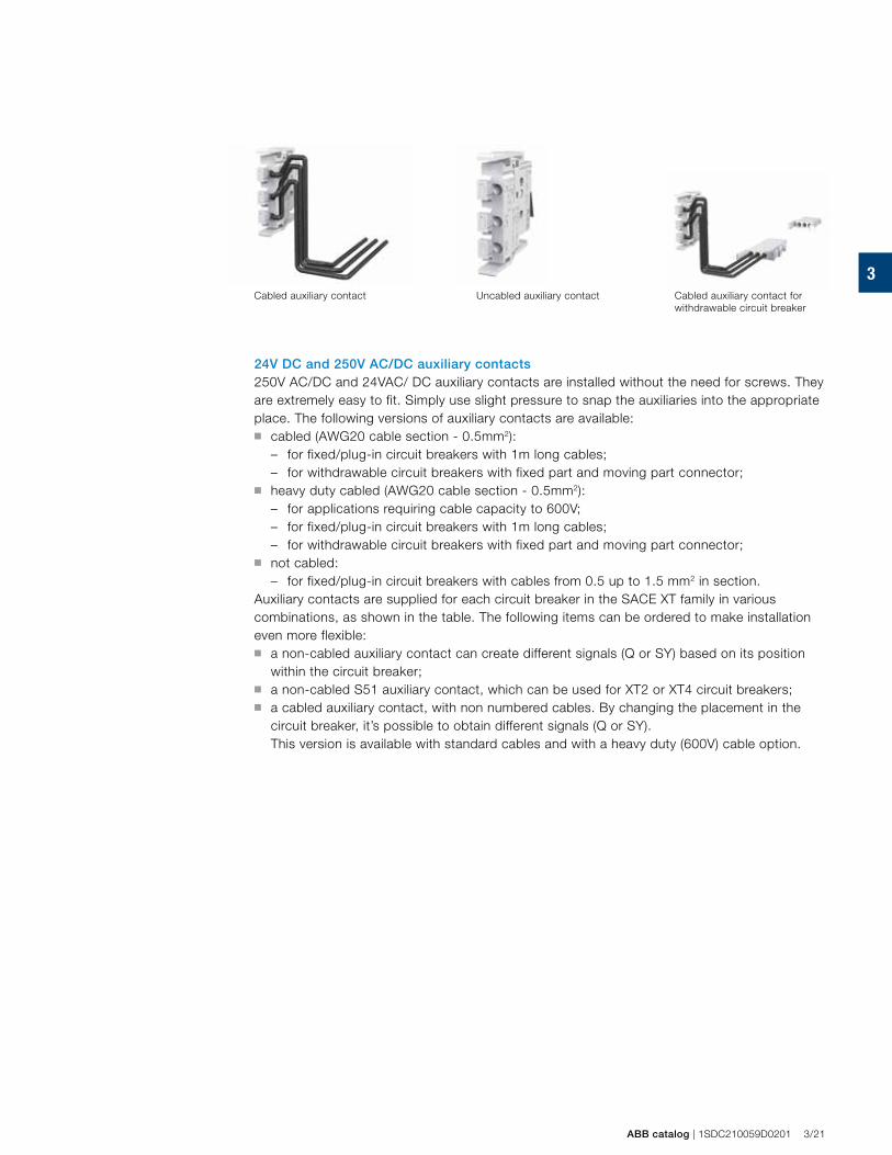
3
ABB catalog | 1SDC210059D0201 3/21
Cabled auxiliary contact Uncabled auxiliary contact Cabled auxiliary contact for withdrawable circuit breaker
24V DC and 250V AC/DC auxiliary contacts250V AC/DC and 24VAC/ DC auxiliary contacts are installed without the need for screws. They are extremely easy to fit. Simply use slight pressure to snap the auxiliaries into the appropriate place. The following versions of auxiliary contacts are available: ■ cabled (AWG20 cable section - 0.5mm2):
– for fixed/plug-in circuit breakers with 1m long cables;– for withdrawable circuit breakers with fixed part and moving part connector;
■ heavy duty cabled (AWG20 cable section - 0.5mm2):– for applications requiring cable capacity to 600V;– for fixed/plug-in circuit breakers with 1m long cables; – for withdrawable circuit breakers with fixed part and moving part connector;
■ not cabled:– for fixed/plug-in circuit breakers with cables from 0.5 up to 1.5 mm2 in section.
Auxiliary contacts are supplied for each circuit breaker in the SACE XT family in various combinations, as shown in the table. The following items can be ordered to make installation even more flexible: ■ a non-cabled auxiliary contact can create different signals (Q or SY) based on its position
within the circuit breaker; ■ a non-cabled S51 auxiliary contact, which can be used for XT2 or XT4 circuit breakers;■ a cabled auxiliary contact, with non numbered cables. By changing the placement in the
circuit breaker, it’s possible to obtain different signals (Q or SY). This version is available with standard cables and with a heavy duty (600V) cable option.
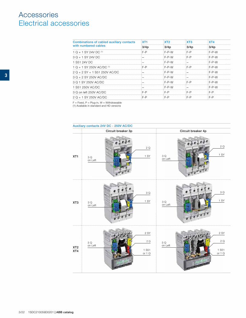
3
3/22 1SDC210059D0201 | ABB catalog
Combinations of cabled auxiliary contacts with numbered cables
XT1 XT2 XT3 XT4
3/4p 3/4p 3/4p 3/4p
1 Q + 1 SY 24V DC (1) F-P F-P-W F-P F-P-W
3 Q + 1 SY 24V DC – F-P-W F-P F-P-W
1 S51 24V DC – F-P-W – F-P-W
1 Q + 1 SY 250V AC/DC (1) F-P F-P-W F-P F-P-W
2 Q + 2 SY + 1 S51 250V AC/DC – F-P-W – F-P-W
3 Q + 2 SY 250V AC/DC – F-P-W – F-P-W
3 Q 1 SY 250V AC/DC – F-P-W F-P F-P-W
1 S51 250V AC/DC – F-P-W – F-P-W
3 Q on left 250V AC/DC F-P F-P F-P F-P
2 Q + 1 SY 250V AC/DC F-P F-P F-P F-P
F = Fixed, P = Plug-in, W = Withdrawable(1) Available in standard and HD versions
Auxiliary contacts 24V DC - 250V AC/DC
Circuit breaker 3p Circuit breaker 4p
XT1 3 Q on Left
1 SY
2 Q
3 Q on Left
1 SY
2 Q
XT3 3 Q on Left
1 SY
3 Q
3 Q on Left
1 SY
3 Q
XT2 XT4
3 Q on Left
2 SY
1 S51 or 1 Q
2 Q 3 Q on Left
2 Q
2 SY
1 S51 or 1 Q
AccessoriesElectrical accessories
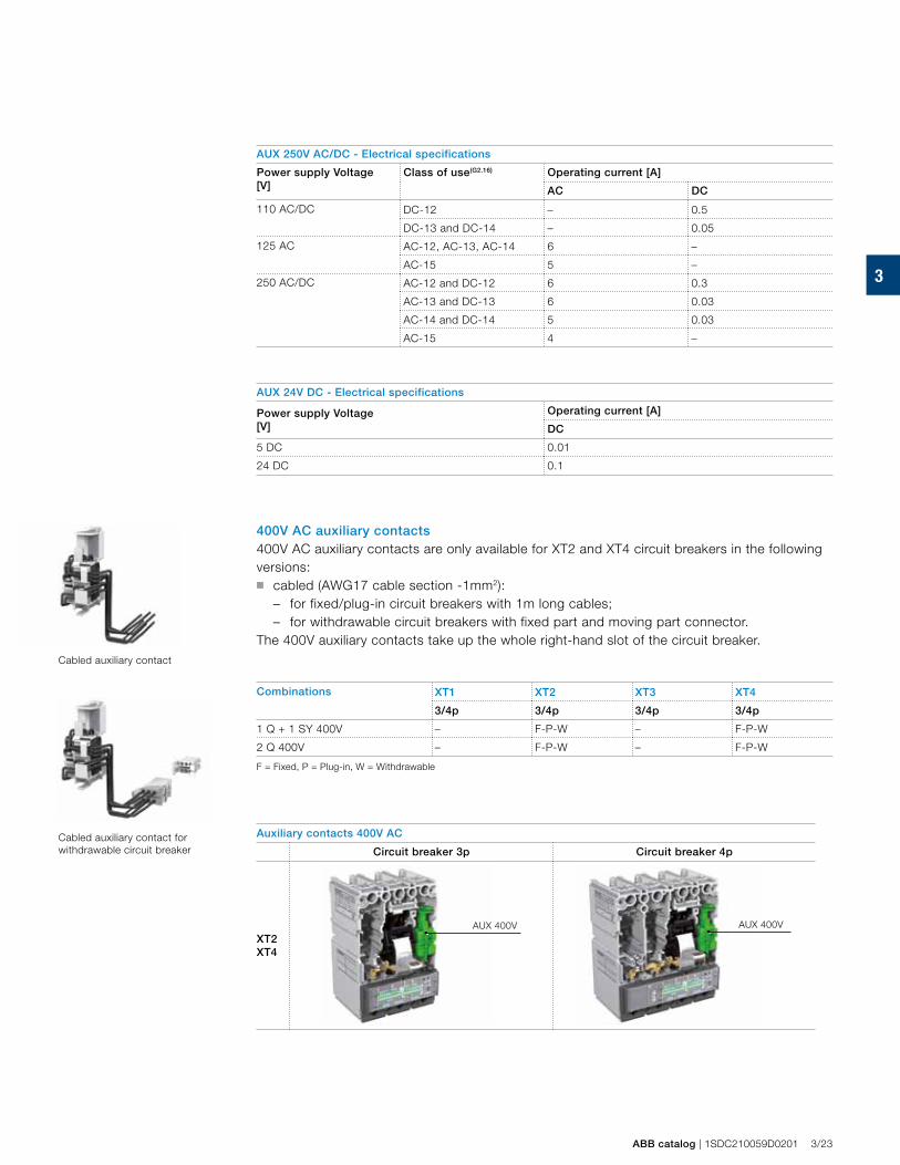
3
ABB catalog | 1SDC210059D0201 3/23
Cabled auxiliary contact
Cabled auxiliary contact for withdrawable circuit breaker
AUX 250V AC/DC - Electrical specifications
Power supply Voltage[V]
Class of use(G2.16) Operating current [A]
AC DC
110 AC/DC DC-12 – 0.5
DC-13 and DC-14 – 0.05
125 AC AC-12, AC-13, AC-14 6 –
AC-15 5 –
250 AC/DC AC-12 and DC-12 6 0.3
AC-13 and DC-13 6 0.03
AC-14 and DC-14 5 0.03
AC-15 4 –
AUX 24V DC - Electrical specifications
Power supply Voltage[V]
Operating current [A]
DC
5 DC 0.01
24 DC 0.1
400V AC auxiliary contacts 400V AC auxiliary contacts are only available for XT2 and XT4 circuit breakers in the following versions: ■ cabled (AWG17 cable section -1mm2):
– for fixed/plug-in circuit breakers with 1m long cables;– for withdrawable circuit breakers with fixed part and moving part connector.
The 400V auxiliary contacts take up the whole right-hand slot of the circuit breaker.
Combinations XT1 XT2 XT3 XT4
3/4p 3/4p 3/4p 3/4p
1 Q + 1 SY 400V – F-P-W – F-P-W
2 Q 400V – F-P-W – F-P-W
F = Fixed, P = Plug-in, W = Withdrawable
Auxiliary contacts 400V AC
Circuit breaker 3p Circuit breaker 4p
XT2 XT4
AUX 400V AUX 400V
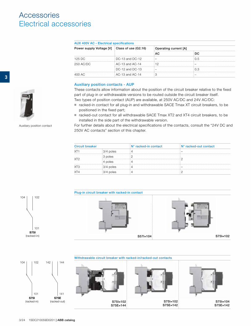
3
101
102104
S75I(racked-in)
101
102104
S75I(racked-in)
141
144142
S75E(racked-out)
3/24 1SDC210059D0201 | ABB catalog
AUX 400V AC - Electrical specifications
Power supply Voltage [V] Class of use (G2.16) Operating current [A]
AC DC
125 DC DC-13 and DC-12 – 0.5
250 AC/DC AC-13 and AC-14 12 –
DC-12 and DC-13 – 0.3
400 AC AC-13 and AC-14 3 –
Auxiliary position contacts - AUPThese contacts allow information about the position of the circuit breaker relative to the fixed part of plug-in or withdrawable versions to be routed outside the circuit breaker itself.Two types of position contact (AUP) are available, at 250V AC/DC and 24V AC/DC:■ racked-in contact for all plug-in and withdrawable SACE Tmax XT circuit breakers, to be
positioned in the fixed part;■ racked-out contact for all withdrawable SACE Tmax XT2 and XT4 circuit breakers, to be
installed in the side part of the withdrawable version.For further details about the electrical specifications of the contacts, consult the “24V DC and 250V AC contacts” section of this chapter.
Circuit breaker N° racked-in contact N° racked-out contact
XT1 3/4 poles 4 –
XT23 poles 2
24 poles 4
XT3 3/4 poles 4 –
XT4 3/4 poles 4 2
Plug-in circuit breaker with racked-in contact
S57I=104 S75I=102
Withdrawable circuit breaker with racked-in/racked-out contacts
S75I=102 S75E=144
S75I=102 S75E=142
S75I=104 S75E=142
Auxiliary position contact
AccessoriesElectrical accessories
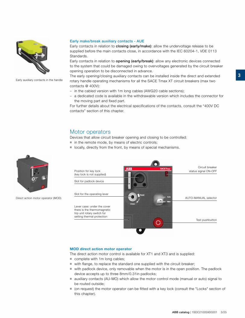
3
ABB catalog | 1SDC210059D0201 3/25
Early auxiliary contacts in the handle
Early make/break auxiliary contacts - AUE Early contacts in relation to closing (early/make): allow the undervoltage release to be supplied before the main contacts close, in accordance with the IEC 60204-1, VDE 0113 Standards.Early contacts in relation to opening (early/break): allow any electronic devices connected to the system that could be damaged owing to overvoltages generated by the circuit breaker opening operation to be disconnected in advance.The early opening/closing auxiliary contacts can be installed inside the direct and extended rotary handle operating mechanisms for all the SACE Tmax XT circuit breakers (max two contacts @ 400V):– in the cabled version with 1m long cables (AWG20 cable sections); – a dedicated code is available in the withdrawable version which includes the connector for
the moving part and fixed part.For further details about the electrical specifications of the contacts, consult the “400V DC contacts” section of this chapter.
Motor operatorsDevices that allow circuit breaker opening and closing to be controlled: ■ in the remote mode, by means of electric controls; ■ locally, directly from the front, by means of special mechanisms.
Direct action motor operator (MOD)
Lever case: under the cover there is the thermomagnetic trip unit rotary switch for setting thermal protection
Slot for the operating lever
Slot for padlock device
Position for key lock (key lock is not supplied)
AUTO-MANUAL selector
Test pushbutton
Circuit breaker status signal ON-OFF
MOD direct action motor operatorThe direct action motor control is available for XT1 and XT3 and is supplied: ■ complete with 1m long cables; ■ with flange, to replace the standard one supplied with the circuit breaker;■ with padlock device, only removable when the motor is in the open position. The padlock
device accepts up to three 8mm/0.31in padlocks;■ auxiliary contacts (AU-MO) which allow the motor control mode (manual or auto) signal to
be routed outside;■ (on request) the motor operator can be fitted with a key lock (consult the "Locks" section of
this chapter).
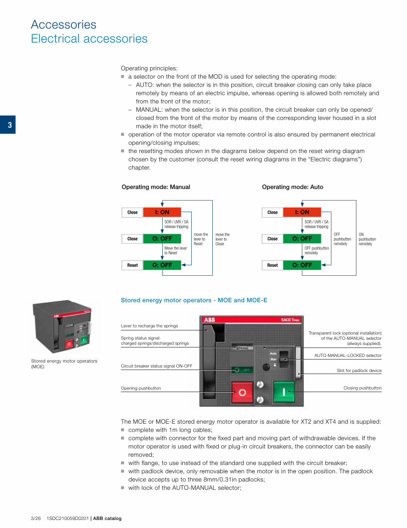
3
I: ON
O: OFF
O: OFF
I: ON
O: OFF
O: OFF
3/26 1SDC210059D0201 | ABB catalog
AccessoriesElectrical accessories
Stored energy motor operators (MOE)
Spring status signal: charged springs/discharged springs
Circuit breaker status signal ON-OFF
Lever to recharge the springs
Opening pushbutton Closing pushbutton
Transparent lock (optional installation) of the AUTO-MANUAL selector
(always supplied).
AUTO-MANUAL-LOCKED selector
Slot for padlock device
Operating principles: ■ a selector on the front of the MOD is used for selecting the operating mode:
– AUTO: when the selector is in this position, circuit breaker closing can only take place remotely by means of an electric impulse, whereas opening is allowed both remotely and from the front of the motor;
– MANUAL: when the selector is in this position, the circuit breaker can only be opened/closed from the front of the motor by means of the corresponding lever housed in a slot made in the motor itself;
■ operation of the motor operator via remote control is also ensured by permanent electrical opening/closing impulses;
■ the resetting modes shown in the diagrams below depend on the reset wiring diagram chosen by the customer (consult the reset wiring diagrams in the “Electric diagrams”) chapter.
Stored energy motor operators - MOE and MOE-E
The MOE or MOE-E stored energy motor operator is available for XT2 and XT4 and is supplied: ■ complete with 1m long cables; ■ complete with connector for the fixed part and moving part of withdrawable devices. If the
motor operator is used with fixed or plug-in circuit breakers, the connector can be easily removed;
■ with flange, to use instead of the standard one supplied with the circuit breaker;■ with padlock device, only removable when the motor is in the open position. The padlock
device accepts up to three 8mm/0.31in padlocks;■ with lock of the AUTO-MANUAL selector;
SOR / UVR / SA release tripping
Move the lever to Reset
SOR / UVR / SArelease tripping
OFF pushbutton remotely
move the lever to Reset
move the lever to Close
OFF pushbutton remotely
ON pushbutton remotely
Close
Close
Reset
Close
Close
Reset
Operating mode: Manual Operating mode: Auto
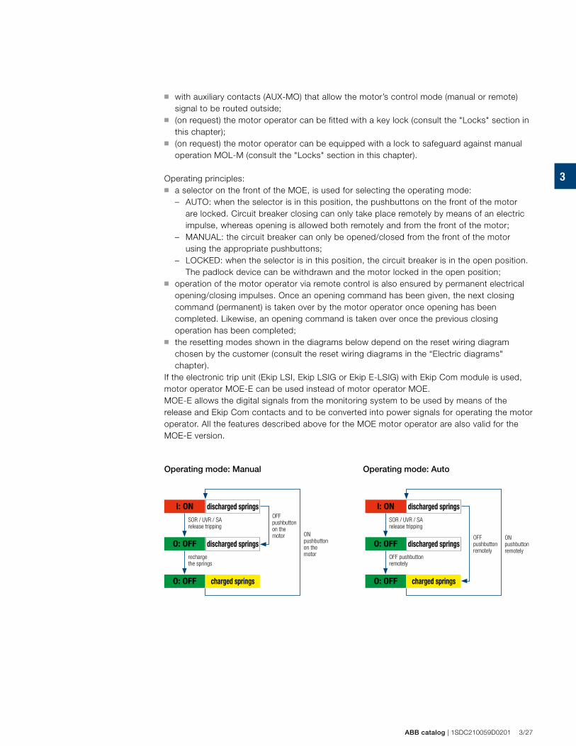
3
I: ON
O: OFF
O: OFF
I: ON
O: OFF
O: OFF
ABB catalog | 1SDC210059D0201 3/27
■ with auxiliary contacts (AUX-MO) that allow the motor’s control mode (manual or remote) signal to be routed outside;
■ (on request) the motor operator can be fitted with a key lock (consult the "Locks" section in this chapter);
■ (on request) the motor operator can be equipped with a lock to safeguard against manual operation MOL-M (consult the "Locks" section in this chapter).
Operating principles: ■ a selector on the front of the MOE, is used for selecting the operating mode:
– AUTO: when the selector is in this position, the pushbuttons on the front of the motor are locked. Circuit breaker closing can only take place remotely by means of an electric impulse, whereas opening is allowed both remotely and from the front of the motor;
– MANUAL: the circuit breaker can only be opened/closed from the front of the motor using the appropriate pushbuttons;
– LOCKED: when the selector is in this position, the circuit breaker is in the open position. The padlock device can be withdrawn and the motor locked in the open position;
■ operation of the motor operator via remote control is also ensured by permanent electrical opening/closing impulses. Once an opening command has been given, the next closing command (permanent) is taken over by the motor operator once opening has been completed. Likewise, an opening command is taken over once the previous closing operation has been completed;
■ the resetting modes shown in the diagrams below depend on the reset wiring diagram chosen by the customer (consult the reset wiring diagrams in the “Electric diagrams" chapter).
If the electronic trip unit (Ekip LSI, Ekip LSIG or Ekip E-LSIG) with Ekip Com module is used, motor operator MOE-E can be used instead of motor operator MOE. MOE-E allows the digital signals from the monitoring system to be used by means of the release and Ekip Com contacts and to be converted into power signals for operating the motor operator. All the features described above for the MOE motor operator are also valid for the MOE-E version.
discharged springs
charged springs
discharged springs
SOR / UVR / SA release tripping
OFF pushbutton on the motor
recharge the springs
ON pushbutton on the motor
discharged springs
charged springs
discharged springs
SOR / UVR / SA release tripping
OFF pushbutton remotely
OFF pushbutton remotely
ON pushbutton remotely
Operating mode: Manual Operating mode: Auto
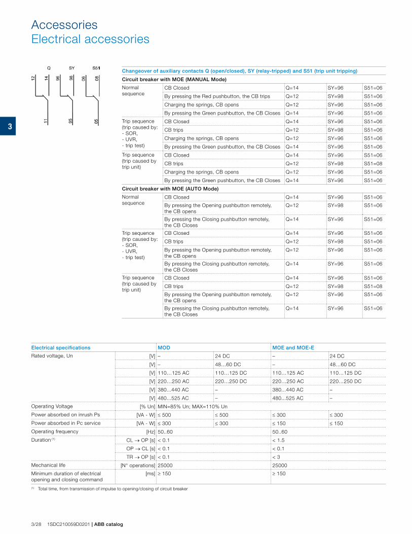
3
3/28 1SDC210059D0201 | ABB catalog
AccessoriesElectrical accessories
Changeover of auxiliary contacts Q (open/closed), SY (relay-tripped) and S51 (trip unit tripping)
Circuit breaker with MOE (MANUAL Mode)
Normal sequence
CB Closed Q=14 SY=96 S51=06
By pressing the Red pushbutton, the CB trips Q=12 SY=98 S51=06
Charging the springs, CB opens Q=12 SY=96 S51=06
By pressing the Green pushbutton, the CB Closes Q=14 SY=96 S51=06
Trip sequence (trip caused by: - SOR, - UVR, - trip test)
CB Closed Q=14 SY=96 S51=06
CB trips Q=12 SY=98 S51=06
Charging the springs, CB opens Q=12 SY=96 S51=06
By pressing the Green pushbutton, the CB Closes Q=14 SY=96 S51=06
Trip sequence (trip caused by trip unit)
CB Closed Q=14 SY=96 S51=06
CB trips Q=12 SY=98 S51=08
Charging the springs, CB opens Q=12 SY=96 S51=06
By pressing the Green pushbutton, the CB Closes Q=14 SY=96 S51=06
Circuit breaker with MOE (AUTO Mode)
Normal sequence
CB Closed Q=14 SY=96 S51=06
By pressing the Opening pushbutton remotely, the CB opens
Q=12 SY=98 S51=06
By pressing the Closing pushbutton remotely, the CB Closes
Q=14 SY=96 S51=06
Trip sequence (trip caused by: - SOR, - UVR, - trip test)
CB Closed Q=14 SY=96 S51=06
CB trips Q=12 SY=98 S51=06
By pressing the Opening pushbutton remotely, the CB opens
Q=12 SY=96 S51=06
By pressing the Closing pushbutton remotely, the CB Closes
Q=14 SY=96 S51=06
Trip sequence (trip caused by trip unit)
CB Closed Q=14 SY=96 S51=06
CB trips Q=12 SY=98 S51=08
By pressing the Opening pushbutton remotely, the CB opens
Q=12 SY=96 S51=06
By pressing the Closing pushbutton remotely, the CB Closes
Q=14 SY=96 S51=06
Electrical specifications MOD MOE and MOE-E
Rated voltage, Un [V] – 24 DC – 24 DC
[V] – 48…60 DC – 48…60 DC
[V] 110…125 AC 110…125 DC 110…125 AC 110…125 DC
[V] 220…250 AC 220…250 DC 220…250 AC 220…250 DC
[V] 380...440 AC – 380...440 AC –
[V] 480...525 AC – 480...525 AC –
Operating Voltage [% Un] MIN=85% Un; MAX=110% Un
Power absorbed on inrush Ps [VA - W] ≤ 500 ≤ 500 ≤ 300 ≤ 300
Power absorbed in Pc service [VA - W] ≤ 300 ≤ 300 ≤ 150 ≤ 150
Operating frequency [Hz] 50..60 50..60
Duration (1) CL → OP [s] < 0.1 < 1.5
OP → CL [s] < 0.1 < 0.1
TR → OP [s] < 0.1 < 3
Mechanical life [N° operations] 25000 25000
Minimum duration of electrical opening and closing command
[ms] ≥ 150 ≥ 150
(1) Total time, from transmission of impulse to opening/closing of circuit breaker
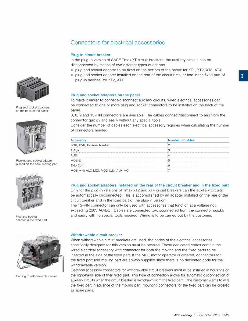
3
ABB catalog | 1SDC210059D0201 3/29
Plug and socket adapter in the fixed part
Plug and socket adapters on the back of the panel
Placked and socket adapter placed on the back moving part
Connectors for electrical accessories Plug-in circuit breaker In the plug-in version of SACE Tmax XT circuit breakers, the auxiliary circuits can be disconnected by means of two different types of adapter:■ plug and socket adapter to be fixed on the bottom of the panel: for XT1, XT2, XT3, XT4;■ plug and socket adapter installed on the rear of the circuit breaker and in the fixed part of
plug-in devices: for XT2, XT4.
Plug and socket adapters on the panelTo make it easier to connect/disconnect auxiliary circuits, wired electrical accessories can be connected to one or more plug and socket connectors to be installed on the back of the panel. 3, 6, 9 and 15-PIN connectors are available. The cables connect/disconnect to and from the connector quickly and easily without any special tools. Consider the number of cables each electrical accessory requires when calculating the number of connectors needed.
Accessory Number of cables
SOR, UVR, External Neutral 2
1 AUX 3
AUE 4
MOE-E 5
Ekip Com 6
MOE (with AUX-MO), MOD (with AUX-MO) 7
Plug and socket adapters installed on the rear of the circuit breaker and in the fixed partOnly for the plug-in versions of Tmax XT2 and XT4 circuit breakers can the auxiliary circuits be automatically disconnected. This is accomplished by an adapter installed on the rear of the circuit breaker and in the fixed part of the plug-in version. The 12-PIN connector can only be used with accessories that function at a voltage not exceeding 250V AC/DC. Cables are connected to/disconnected from the connector quickly and easily with no special tools required. Wiring is to be carried out by the customer.
Withdrawable circuit breakerWhen withdrawable circuit breakers are used, the codes of the electrical accessories specifically designed for this version must be ordered. These dedicated codes contain the wired electrical accessory with connector for both the moving and the fixed parts to be inserted in the side of the fixed part. If the MOE motor operator is ordered, connectors for the fixed part and moving part are always supplied since there is no dedicated code for the withdrawable version. Electrical accessory connectors for withdrawable circuit breakers must all be installed in housings on the right-hand side of their fixed part. This type of connection allows for automatic disconnection of auxiliary circuits when the circuit breaker is withdrawn from the fixed part. If the customer wants to wire the fixed part in advance of the moving part, mounting connectors for the fixed part can be ordered as spare parts.
Cabling of withdrawable version
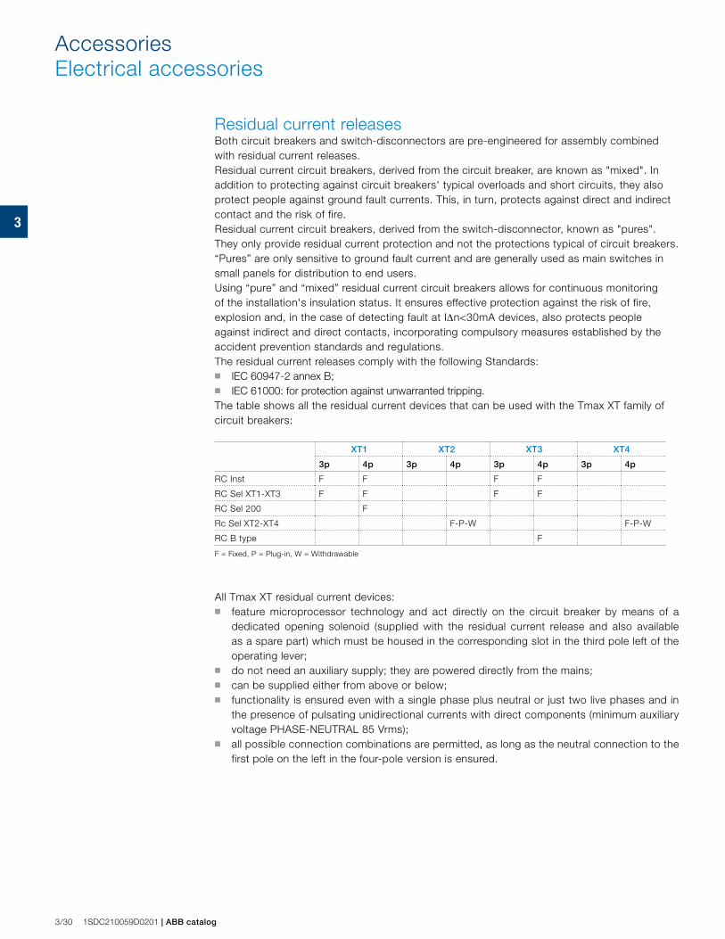
3
3/30 1SDC210059D0201 | ABB catalog
AccessoriesElectrical accessories
Residual current releasesBoth circuit breakers and switch-disconnectors are pre-engineered for assembly combined with residual current releases. Residual current circuit breakers, derived from the circuit breaker, are known as "mixed". In addition to protecting against circuit breakers' typical overloads and short circuits, they also protect people against ground fault currents. This, in turn, protects against direct and indirect contact and the risk of fire. Residual current circuit breakers, derived from the switch-disconnector, known as "pures". They only provide residual current protection and not the protections typical of circuit breakers. “Pures” are only sensitive to ground fault current and are generally used as main switches in small panels for distribution to end users.Using “pure” and “mixed” residual current circuit breakers allows for continuous monitoring of the installation's insulation status. It ensures effective protection against the risk of fire, explosion and, in the case of detecting fault at IΔn<30mA devices, also protects people against indirect and direct contacts, incorporating compulsory measures established by the accident prevention standards and regulations.The residual current releases comply with the following Standards:■ IEC 60947-2 annex B;■ IEC 61000: for protection against unwarranted tripping.The table shows all the residual current devices that can be used with the Tmax XT family of circuit breakers:
XT1 XT2 XT3 XT4
3p 4p 3p 4p 3p 4p 3p 4p
RC Inst F F F F
RC Sel XT1-XT3 F F F F
RC Sel 200 F
Rc Sel XT2-XT4 F-P-W F-P-W
RC B type F
F = Fixed, P = Plug-in, W = Withdrawable
All Tmax XT residual current devices: ■ feature microprocessor technology and act directly on the circuit breaker by means of a
dedicated opening solenoid (supplied with the residual current release and also available as a spare part) which must be housed in the corresponding slot in the third pole left of the operating lever;
■ do not need an auxiliary supply; they are powered directly from the mains;■ can be supplied either from above or below;■ functionality is ensured even with a single phase plus neutral or just two live phases and in
the presence of pulsating unidirectional currents with direct components (minimum auxiliary voltage PHASE-NEUTRAL 85 Vrms);
■ all possible connection combinations are permitted, as long as the neutral connection to the first pole on the left in the four-pole version is ensured.
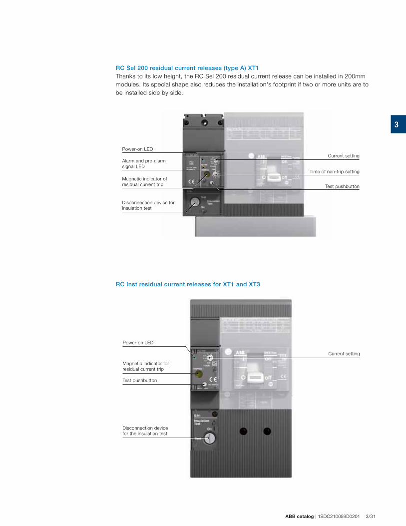
3
ABB catalog | 1SDC210059D0201 3/31
RC Inst residual current releases for XT1 and XT3
RC Sel 200 residual current releases (type A) XT1 Thanks to its low height, the RC Sel 200 residual current release can be installed in 200mm modules. Its special shape also reduces the installation's footprint if two or more units are to be installed side by side.
Current settingPower-on LED
Alarm and pre-alarm signal LED
Magnetic indicator of residual current trip
Time of non-trip setting
Test pushbutton
Disconnection device for insulation test
Current setting
Power-on LED
Magnetic indicator for residual current trip
Test pushbutton
Disconnection device for the insulation test
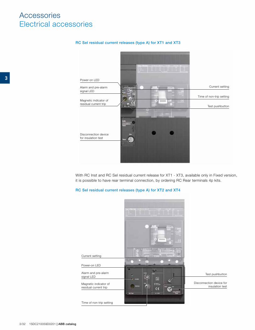
3
3/32 1SDC210059D0201 | ABB catalog
AccessoriesElectrical accessories
With RC Inst and RC Sel residual current release for XT1 - XT3, available only in Fixed version, it is possible to have rear terminal connection, by ordering RC Rear terminals 4p kits.
RC Sel residual current releases (type A) for XT2 and XT4
RC Sel residual current releases (type A) for XT1 and XT3
Current setting
Power-on LED
Alarm and pre-alarm signal LED
Magnetic indicator of residual current trip
Test pushbutton
Disconnection device for insulation test
Current setting
Power-on LED
Alarm and pre-alarm signal LED
Magnetic indicator of residual current trip
Time of non-trip setting
Test pushbutton
Disconnection device for insulation test
Time of non-trip setting
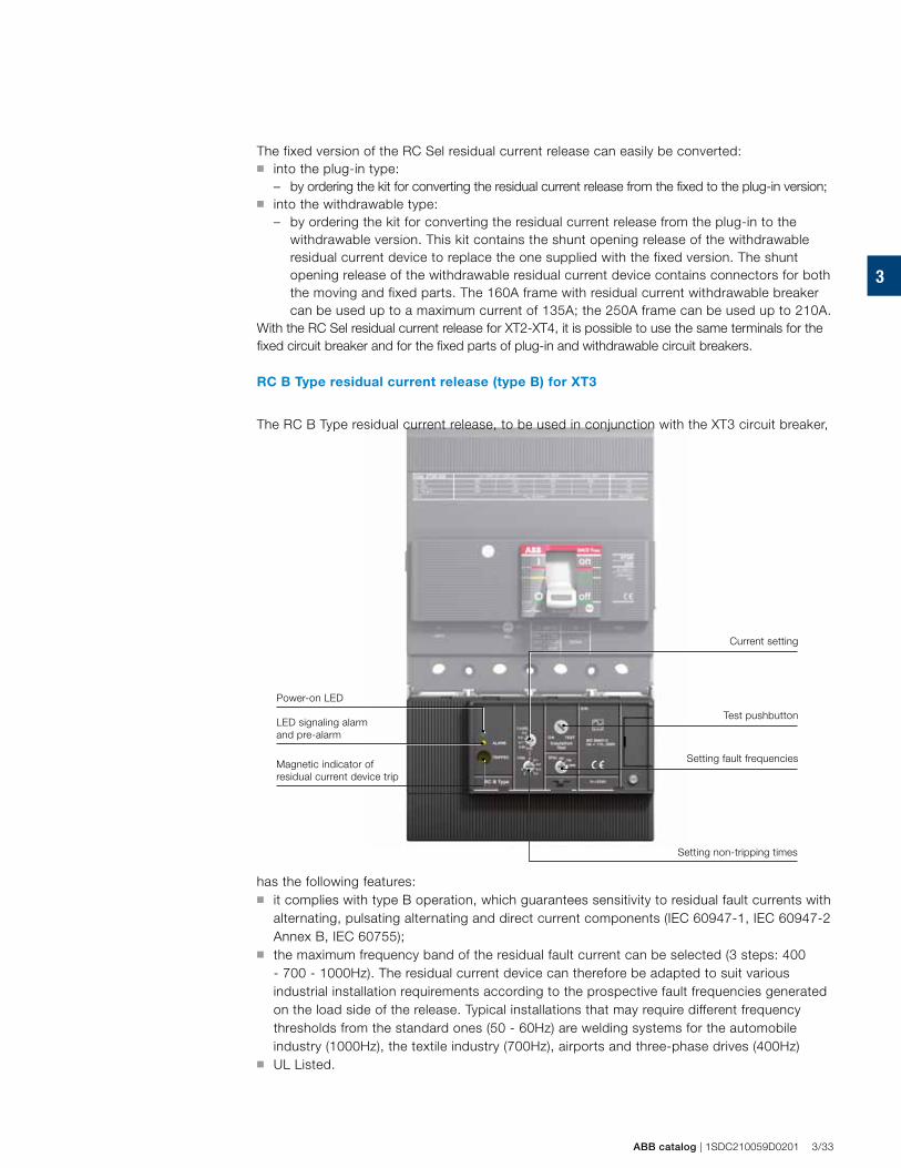
3
ABB catalog | 1SDC210059D0201 3/33
The fixed version of the RC Sel residual current release can easily be converted: ■ into the plug-in type:
– by ordering the kit for converting the residual current release from the fixed to the plug-in version;■ into the withdrawable type:
– by ordering the kit for converting the residual current release from the plug-in to the withdrawable version. This kit contains the shunt opening release of the withdrawable residual current device to replace the one supplied with the fixed version. The shunt opening release of the withdrawable residual current device contains connectors for both the moving and fixed parts. The 160A frame with residual current withdrawable breaker can be used up to a maximum current of 135A; the 250A frame can be used up to 210A.
With the RC Sel residual current release for XT2-XT4, it is possible to use the same terminals for the fixed circuit breaker and for the fixed parts of plug-in and withdrawable circuit breakers.
RC B Type residual current release (type B) for XT3
The RC B Type residual current release, to be used in conjunction with the XT3 circuit breaker,
has the following features: ■ it complies with type B operation, which guarantees sensitivity to residual fault currents with
alternating, pulsating alternating and direct current components (IEC 60947-1, IEC 60947-2 Annex B, IEC 60755);
■ the maximum frequency band of the residual fault current can be selected (3 steps: 400 - 700 - 1000Hz). The residual current device can therefore be adapted to suit various industrial installation requirements according to the prospective fault frequencies generated on the load side of the release. Typical installations that may require different frequency thresholds from the standard ones (50 - 60Hz) are welding systems for the automobile industry (1000Hz), the textile industry (700Hz), airports and three-phase drives (400Hz)
■ UL Listed.
Setting non-tripping times
LED signaling alarm and pre-alarm
Power-on LED
Magnetic indicator of residual current device trip
Test pushbutton
Current setting
Setting fault frequencies
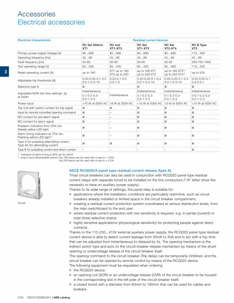
3
3/34 1SDC210059D0201 | ABB catalog
AccessoriesElectrical accessories
Electrical characteristic Residual current devices
RC Sel 200mm XT1
RC InstXT1-XT3
RC Sel XT1-XT3
RC Sel XT2-XT4
RC B TypeXT3
Primary power supply Voltage [V] 85…690 85…690 85…690 85…690 110…500
Operating frequency [Hz] 45…66 45…66 45…66 45…66 45…66
Fault frequency [Hz] 50-60 50-60 50-60 50-60 400-700-1000
Test operating range [V] 85…500 85…500 85…500 85…690 110…500
Rated operating current [A] up to 160 XT1 up to 160 XT3 up to 250
up to 160 XT1up to 250 XT3
up to 160 XT2(2)
up to 250 XT4(2) up to 225
Adjustable trip thresholds [A]0.03-0.05-0.1-0.30.5-1-3-5-10
0.03-0.1-0.30.5-1-3
0.03-0.05-0.1-0.30.5-1-3-5-10
0.03-0.05-0.1-0.30.5-1-3-5-10
0.03-0.05-0.10.3-0.5-1
Selective type S ■ – ■ ■ ■
Adjustable NON-trip time settings [s]at 2xIΔn
instantaneousinstantaneous
instantaneous instantaneous instantaneous
0.1-0.2-0.3-0.5-1-2-3
0.1-0.2-0.3-0.5-1-2-3
0.1-0.2-0.3-0.5-1-2-3
0-0.1-0.2-0.3-0.5-1-2-3
Power input <10 W at 500V AC <8 W at 500V AC <10 W at 500V AC <5 W at 500V AC <10 W at 500V AC
Trip Coil with switch contact for trip signal ■ ■ ■ ■ ■
Input for remote controlled opening command ■ – ■ ■ ■
NO contact for pre-alarm signal ■ – ■ ■ ■
NO contact for alarm signal ■ – ■ ■ ■
Prealarm indication from 25% IΔn. Steady yellow LED light ■ – ■ ■ ■
Alarm timing indication at 75% IΔn. Flashing yellow LED light(1) ■ – ■ ■ ■
Type A for pulsating alternating current,Type AC for alternating current ■ ■ ■ ■ ■
Type B for pulsating current and direct current – – – – ■
(1) indication of alarm timing at 90% IΔn for 30mA(2) plug-in and withdrawable version: the 160 frame can be used with a max In = 135A the 250 frame can be used with a max In = 210A
SACE RCQ020/A panel type residual current release (type A)Tmax circuit breakers can also be used in conjunction with RCQ020 panel type residual current relays with separate toroid to be installed on the line conductors ("/A" letter show the necessity to have on auxiliary power supply).Thanks to its wide range of settings, the panel relay is suitable for: ■ applications where the installation conditions are particularly restrictive, such as circuit
breakers already installed or limited space in the circuit breaker compartment;■ creating a residual current protection system coordinated at various distribution levels, from
the main switchboard to the end user;■ where residual current protection with low sensitivity is required, e.g. in partial (current) or
total (time) selective chains;■ highly sensitive applications (physiological sensitivity) for protecting people against direct
contacts.Thanks to the 115-230...415V external auxiliary power supply, the RCQ020 panel-type residual current device is able to detect current leakage from 30mA to 30A and to act with a trip time that can be adjusted from instantaneous to delayed by 5s. The opening mechanism is the indirect action type and acts on the circuit breaker release mechanism by means of the shunt opening or undervoltage release of the circuit breaker itself. The opening command to the circuit breaker (Trip delay) can be temporarily inhibited, and the circuit breaker can be opened by remote control by means of the RCQ020 device.The following equipment must be requested when ordering: ■ the RCQ020 device; ■ an opening coil (SOR) or an undervoltage release (UVR) of the circuit breaker to be housed
in the corresponding slot in the left pole of the circuit breaker itself; ■ a closed toroid with a diameter from 60mm to 185mm that can be used for cables and
busbars.
Toroid
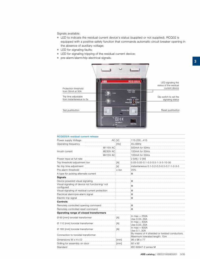
3
ABB catalog | 1SDC210059D0201 3/35
Signals available: ■ LED to indicate the residual current device's status (supplied or not supplied). RCQ02 is
equipped with a positive safety function that commands automatic circuit breaker opening in the absence of auxiliary voltage;
■ LED for signaling faults; ■ LED for signaling tripping of the residual current device; ■ pre-alarm/alarm/trip electrical signals.
Protection threshold from 30mA at 30A
Trip time adjustable from instantaneous to 5s
Test pushbutton
LED signaling the status of the residual
current device
Dip-switch to set the signaling status
Reset pushbutton
RCQ020/A residual current release
Power supply Voltage AC [V] 115-230...415
Operating frequency [Hz] 45÷66Hz
@115V AC 500mA for 50ms
Inrush current @230V AC 150mA for 50ms
@415V AC 100mA for 50ms
Power input at full rate 2 [VA] / 2 [W]
Trip threshold adjustment IΔn [A] 0.03-0.05-0.1-0.3-0.5-1-3-5-10-30
No trip time adjustment [s] instantaneous 0.1-0.2-0.3-0.5-0.7-1-2-3-5
Pre-alarm threshold x IΔn 25%
A type for pulsing alternate current ■
Signals
Device powered visual signaling ■
Visual signaling of device not functioning/ not configured ■
Visual signaling of residual current protection ■
Electrical alarm/pre-alarm signal ■
Electric trip signal ■
Controls
Remotely controlled opening command ■
Remotely controlled reset command ■
Operating range of closed transformers
Ø 60 [mm] toroidal transformer [A]In max = 250AUse 0.03..30A
Ø 110 [mm] toroidal transformer [A]In max = 400AUse 0.03..30A
Ø 185 [mm] toroidal transformer [A]In max = 800AUse 0.1..30A
Connection to toroidal transformerBy means of 4 shielded or twisted conductors. Maximum tolerated length: 15m
Dimensions W x H x D [mm] 96 x 96 x 77
Drilling for assembly on door [mm] 92 x 92
Standard IEC 60947-2 annex M
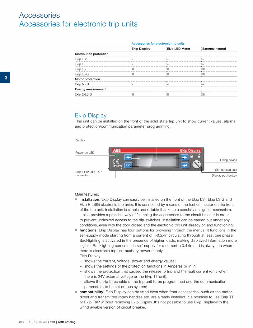
3
3/36 1SDC210059D0201 | ABB catalog
Accessories for electronic trip units
Ekip Display Ekip LED Meter External neutral
Distribution protection
Ekip LS/I – – –
Ekip I – – –
Ekip LSI ■ ■ ■
Ekip LSIG ■ ■ ■
Motor protection
Ekip M-LIU – – –
Energy measurement
Ekip E-LSIG ■ ■ ■
Ekip DisplayThis unit can be installed on the front of the solid state trip unit to show current values, alarms and protection/communication parameter programming.
Display pushbutton
Power-on LED
Display
Fixing device
Ekip TT or Ekip T&P connector
Slot for lead seal
AccessoriesAccessories for electronic trip units
Main features: ■ installation: Ekip Display can easily be installed on the front of the Ekip LSI, Ekip LSIG and
Ekip E-LSIG electronic trip units. It is connected by means of the test connector on the front of the trip unit. Installation is simple and reliable thanks to a specially designed mechanism. It also provides a practical way of fastening the accessories to the circuit breaker in order to prevent undesired access to the dip-switches. Installation can be carried out under any conditions, even with the door closed and the electronic trip unit already on and functioning;
■ functions: Ekip Display has four buttons for browsing through the menus. It functions in the self-supply mode starting from a current of I>0.2xIn circulating through at least one phase. Backlighting is activated in the presence of higher loads, making displayed information more legible. Backlighting comes on in self-supply for a current I>0.4xIn and is always on when there is electronic trip unit auxiliary power supply.
Ekip Display: – shows the current, voltage, power and energy values;– shows the settings of the protection functions in Amperes or in In;– shows the protection that caused the release to trip and the fault current (only when
there is 24V external voltage or the Ekip TT unit); – allows the trip thresholds of the trip unit to be programmed and the communication
parameters to be set on bus system;■ compatibility: Ekip Display can be fitted even when front accessories, such as the motor,
direct and transmitted rotary handles etc. are already installed. It's possible to use Ekip TT or Ekip T&P without removing Ekip Display. It's not possible to use Ekip Displaywith the withdrawable version of circuit breaker.
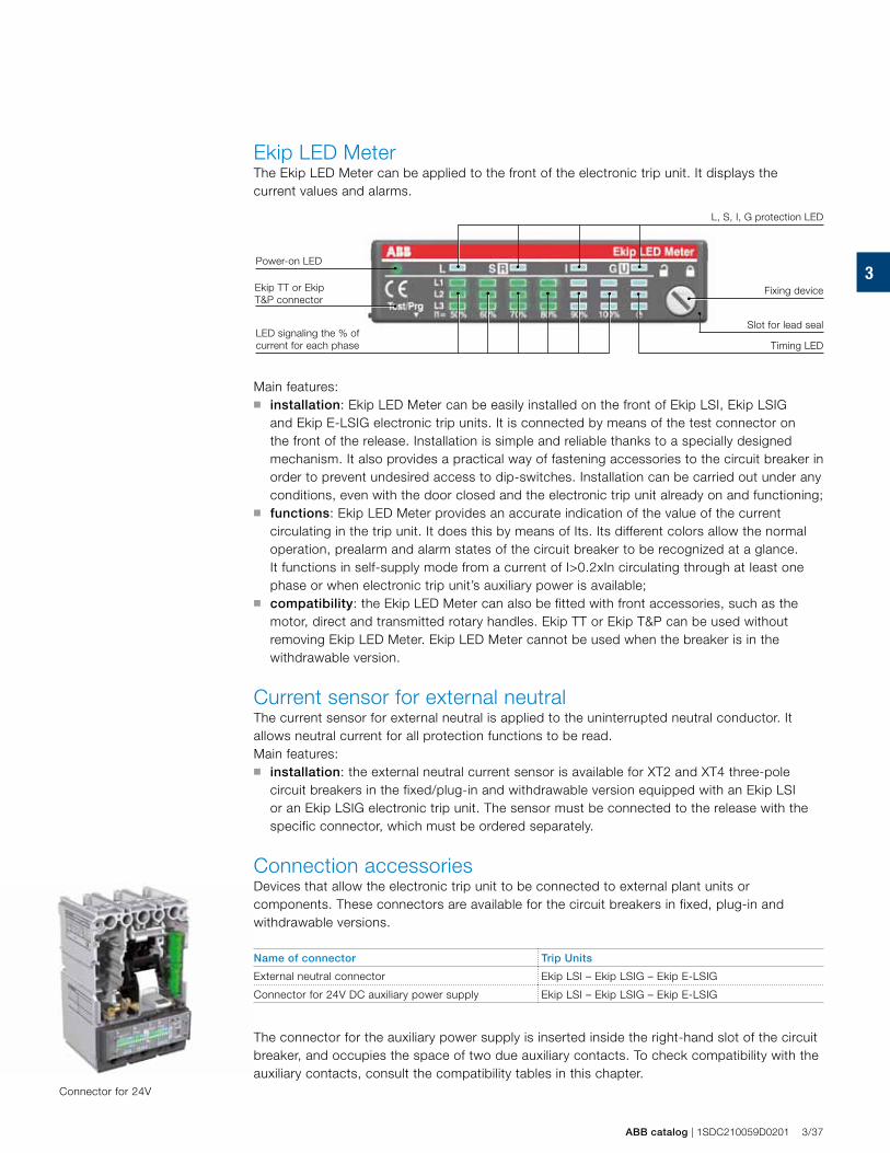
3
ABB catalog | 1SDC210059D0201 3/37
Ekip LED MeterThe Ekip LED Meter can be applied to the front of the electronic trip unit. It displays the current values and alarms.
Main features:■ installation: Ekip LED Meter can be easily installed on the front of Ekip LSI, Ekip LSIG
and Ekip E-LSIG electronic trip units. It is connected by means of the test connector on the front of the release. Installation is simple and reliable thanks to a specially designed mechanism. It also provides a practical way of fastening accessories to the circuit breaker in order to prevent undesired access to dip-switches. Installation can be carried out under any conditions, even with the door closed and the electronic trip unit already on and functioning;
■ functions: Ekip LED Meter provides an accurate indication of the value of the current circulating in the trip unit. It does this by means of Its. Its different colors allow the normal operation, prealarm and alarm states of the circuit breaker to be recognized at a glance. It functions in self-supply mode from a current of I>0.2xIn circulating through at least one phase or when electronic trip unit’s auxiliary power is available;
■ compatibility: the Ekip LED Meter can also be fitted with front accessories, such as the motor, direct and transmitted rotary handles. Ekip TT or Ekip T&P can be used without removing Ekip LED Meter. Ekip LED Meter cannot be used when the breaker is in the withdrawable version.
Current sensor for external neutralThe current sensor for external neutral is applied to the uninterrupted neutral conductor. It allows neutral current for all protection functions to be read. Main features:■ installation: the external neutral current sensor is available for XT2 and XT4 three-pole
circuit breakers in the fixed/plug-in and withdrawable version equipped with an Ekip LSI or an Ekip LSIG electronic trip unit. The sensor must be connected to the release with the specific connector, which must be ordered separately.
Connection accessoriesDevices that allow the electronic trip unit to be connected to external plant units or components. These connectors are available for the circuit breakers in fixed, plug-in and withdrawable versions.
Name of connector Trip Units
External neutral connector Ekip LSI – Ekip LSIG – Ekip E-LSIG
Connector for 24V DC auxiliary power supply Ekip LSI – Ekip LSIG – Ekip E-LSIG
The connector for the auxiliary power supply is inserted inside the right-hand slot of the circuit breaker, and occupies the space of two due auxiliary contacts. To check compatibility with the auxiliary contacts, consult the compatibility tables in this chapter.
Power-on LED
LED signaling the % of current for each phase Timing LED
Fixing device
L, S, I, G protection LED
Ekip TT or Ekip T&P connector
Slot for lead seal
Connector for 24V

3
3/38 1SDC210059D0201 | ABB catalog
HMI030 interface on the front of the switchboardHMI030 is an interface on the front of the switchboard and is usable with protection trip units fitted with Ekip Com.
AccessoriesCommunication devices and systems
Main features:■ installation: HMI030 can be fitted into the hole in the door using the automatic click-in
method. In situations where mechanical stress is particularly intense, it can also be installed by using the special clips supplied. It must be connected directly to the Ekip LSI, Ekip LSIG or Ekip E-LSIG protection trip unit with Ekip Com via the serial communication line. HMI030 requires a 24V DC power supply;
■ functions: HMI030 consists of a graphic display and 4 buttons for browsing through the menus. This accessory allows you to view: – the measurements taken by the release to which it is connected;– the alarms/events of the release.
Thanks to its high level of accuracy, the same as that of the trip unit protection, the device is a valid substitute for conventional instruments without any additional current transformers.
■ communication: HMI030 is provided with two communication lines. Either one can be used.– Modbus– Local Bus.
Connecting Ekip LSI, Ekip LSIG or Ekip E-LSIG to the Local Bus allows the Modbus line to be connected to a different communication network.
Consult the "Electrical diagrams" chapter for further details about wiring.
Alarm LED
Display
Display pushbutton
LED signaling the % of current for each phase
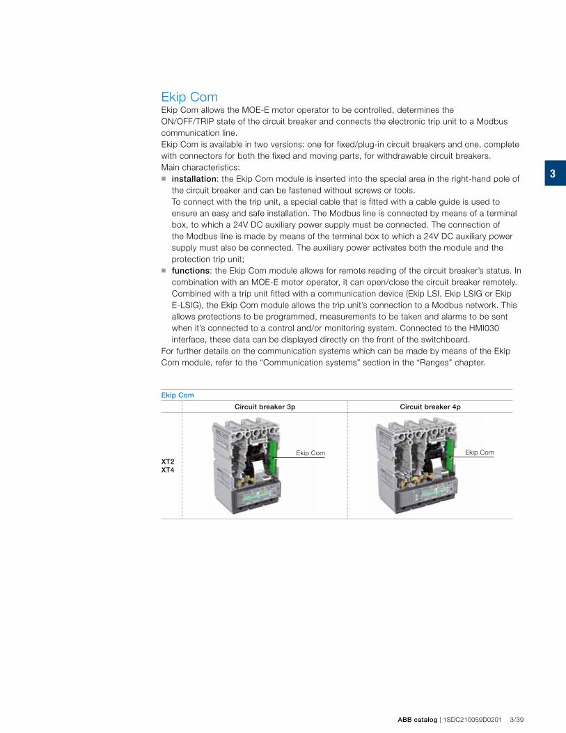
3
ABB catalog | 1SDC210059D0201 3/39
Ekip ComEkip Com allows the MOE-E motor operator to be controlled, determines the ON/OFF/TRIP state of the circuit breaker and connects the electronic trip unit to a Modbus communication line.Ekip Com is available in two versions: one for fixed/plug-in circuit breakers and one, complete with connectors for both the fixed and moving parts, for withdrawable circuit breakers. Main characteristics:■ installation: the Ekip Com module is inserted into the special area in the right-hand pole of
the circuit breaker and can be fastened without screws or tools. To connect with the trip unit, a special cable that is fitted with a cable guide is used to
ensure an easy and safe installation. The Modbus line is connected by means of a terminal box, to which a 24V DC auxiliary power supply must be connected. The connection of the Modbus line is made by means of the terminal box to which a 24V DC auxiliary power supply must also be connected. The auxiliary power activates both the module and the protection trip unit;
■ functions: the Ekip Com module allows for remote reading of the circuit breaker’s status. In combination with an MOE-E motor operator, it can open/close the circuit breaker remotely. Combined with a trip unit fitted with a communication device (Ekip LSI, Ekip LSIG or Ekip E-LSIG), the Ekip Com module allows the trip unit’s connection to a Modbus network. This allows protections to be programmed, measurements to be taken and alarms to be sent when it’s connected to a control and/or monitoring system. Connected to the HMI030 interface, these data can be displayed directly on the front of the switchboard.
For further details on the communication systems which can be made by means of the Ekip Com module, refer to the “Communication systems” section in the “Ranges” chapter.
Ekip Com
Circuit breaker 3p Circuit breaker 4p
XT2 XT4
Ekip Com Ekip Com
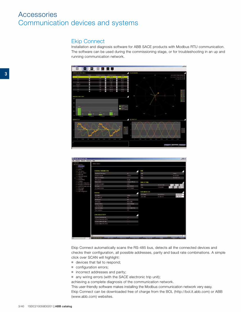
3
3/40 1SDC210059D0201 | ABB catalog
Ekip ConnectInstallation and diagnosis software for ABB SACE products with Modbus RTU communication. The software can be used during the commissioning stage, or for troubleshooting in an up and running communication network.
Ekip Connect automatically scans the RS-485 bus, detects all the connected devices and checks their configuration, all possible addresses, parity and baud rate combinations. A simple click over SCAN will highlight: ■ devices that fail to respond;■ configuration errors;■ incorrect addresses and parity;■ any wiring errors (with the SACE electronic trip unit);achieving a complete diagnosis of the communication network. This user-friendly software makes installing the Modbus communication network very easy.Ekip Connect can be downloaded free of charge from the BOL (http://bol.it.abb.com) or ABB (www.abb.com) websites.
AccessoriesCommunication devices and systems
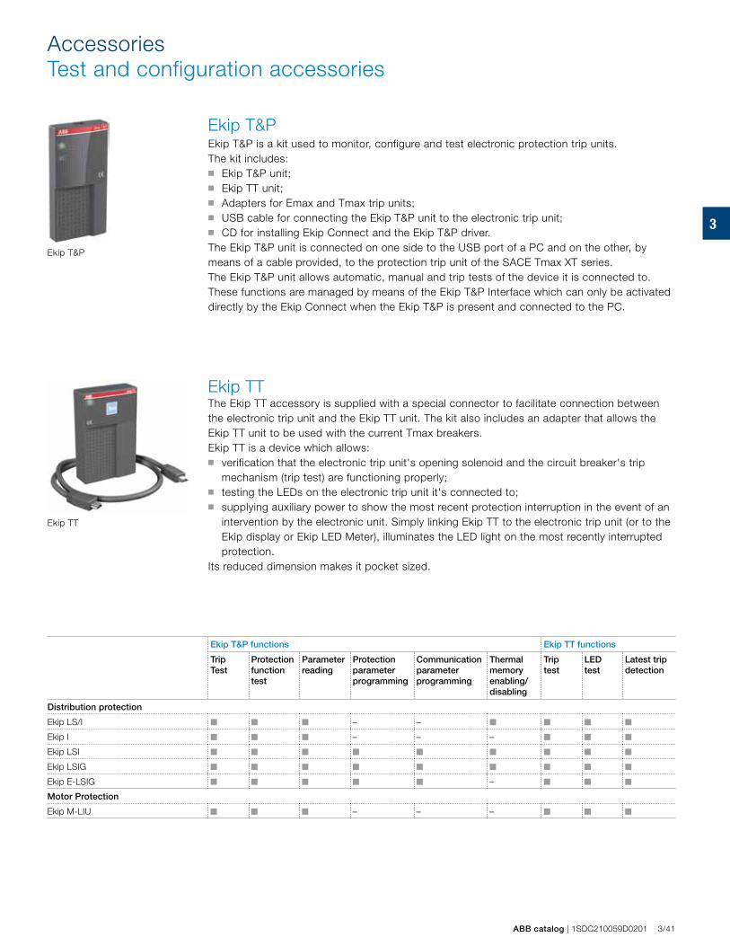
3
Ekip TT
Ekip T&P
ABB catalog | 1SDC210059D0201 3/41
Ekip TT The Ekip TT accessory is supplied with a special connector to facilitate connection between the electronic trip unit and the Ekip TT unit. The kit also includes an adapter that allows the Ekip TT unit to be used with the current Tmax breakers.Ekip TT is a device which allows:■ verification that the electronic trip unit's opening solenoid and the circuit breaker's trip
mechanism (trip test) are functioning properly;■ testing the LEDs on the electronic trip unit it's connected to;■ supplying auxiliary power to show the most recent protection interruption in the event of an
intervention by the electronic unit. Simply linking Ekip TT to the electronic trip unit (or to the Ekip display or Ekip LED Meter), illuminates the LED light on the most recently interrupted protection.
Its reduced dimension makes it pocket sized.
Ekip T&P functions Ekip TT functions
Trip Test
Protection function test
Parameterreading
Protectionparameter programming
Communication parameter programming
Thermal memory enabling/disabling
Trip test
LED test
Latest trip detection
Distribution protection
Ekip LS/I ■ ■ ■ – – ■ ■ ■ ■
Ekip I ■ ■ ■ – – – ■ ■ ■
Ekip LSI ■ ■ ■ ■ ■ ■ ■ ■ ■
Ekip LSIG ■ ■ ■ ■ ■ ■ ■ ■ ■
Ekip E-LSIG ■ ■ ■ ■ ■ – ■ ■ ■
Motor Protection
Ekip M-LIU ■ ■ ■ – – – ■ ■ ■
AccessoriesTest and configuration accessories
Ekip T&PEkip T&P is a kit used to monitor, configure and test electronic protection trip units.The kit includes:■ Ekip T&P unit;■ Ekip TT unit;■ Adapters for Emax and Tmax trip units;■ USB cable for connecting the Ekip T&P unit to the electronic trip unit;■ CD for installing Ekip Connect and the Ekip T&P driver.The Ekip T&P unit is connected on one side to the USB port of a PC and on the other, by means of a cable provided, to the protection trip unit of the SACE Tmax XT series.The Ekip T&P unit allows automatic, manual and trip tests of the device it is connected to. These functions are managed by means of the Ekip T&P Interface which can only be activated directly by the Ekip Connect when the Ekip T&P is present and connected to the PC.
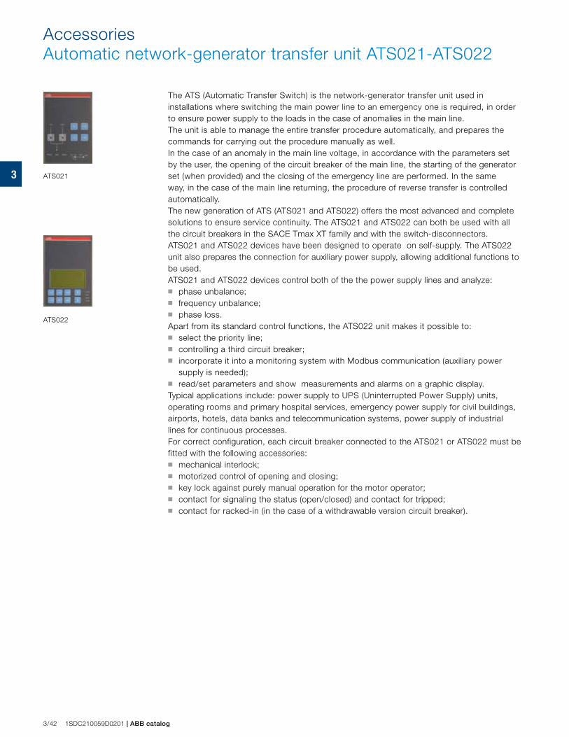
3 ATS021
ATS022
3/42 1SDC210059D0201 | ABB catalog
The ATS (Automatic Transfer Switch) is the network-generator transfer unit used in installations where switching the main power line to an emergency one is required, in order to ensure power supply to the loads in the case of anomalies in the main line.The unit is able to manage the entire transfer procedure automatically, and prepares the commands for carrying out the procedure manually as well.In the case of an anomaly in the main line voltage, in accordance with the parameters set by the user, the opening of the circuit breaker of the main line, the starting of the generator set (when provided) and the closing of the emergency line are performed. In the same way, in the case of the main line returning, the procedure of reverse transfer is controlled automatically.The new generation of ATS (ATS021 and ATS022) offers the most advanced and complete solutions to ensure service continuity. The ATS021 and ATS022 can both be used with all the circuit breakers in the SACE Tmax XT family and with the switch-disconnectors.ATS021 and ATS022 devices have been designed to operate on self-supply. The ATS022 unit also prepares the connection for auxiliary power supply, allowing additional functions to be used.ATS021 and ATS022 devices control both of the the power supply lines and analyze:■ phase unbalance;■ frequency unbalance;■ phase loss.Apart from its standard control functions, the ATS022 unit makes it possible to:■ select the priority line;■ controlling a third circuit breaker;■ incorporate it into a monitoring system with Modbus communication (auxiliary power
supply is needed);■ read/set parameters and show measurements and alarms on a graphic display.Typical applications include: power supply to UPS (Uninterrupted Power Supply) units, operating rooms and primary hospital services, emergency power supply for civil buildings, airports, hotels, data banks and telecommunication systems, power supply of industrial lines for continuous processes.For correct configuration, each circuit breaker connected to the ATS021 or ATS022 must be fitted with the following accessories: ■ mechanical interlock;■ motorized control of opening and closing;■ key lock against purely manual operation for the motor operator;■ contact for signaling the status (open/closed) and contact for tripped;■ contact for racked-in (in the case of a withdrawable version circuit breaker).
AccessoriesAutomatic network-generator transfer unit ATS021-ATS022
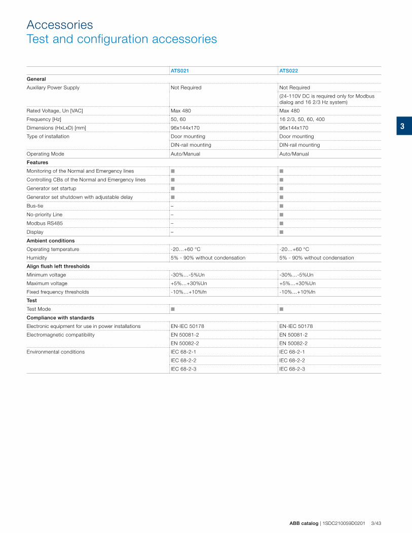
3
ABB catalog | 1SDC210059D0201 3/43
AccessoriesTest and configuration accessories
ATS021 ATS022
General
Auxiliary Power Supply Not Required Not Required
(24-110V DC is required only for Modbus dialog and 16 2/3 Hz system)
Rated Voltage, Un [VAC] Max 480 Max 480
Frequency [Hz] 50, 60 16 2/3, 50, 60, 400
Dimensions (HxLxD) [mm] 96x144x170 96x144x170
Type of installation Door mounting Door mounting
DIN-rail mounting DIN-rail mounting
Operating Mode Auto/Manual Auto/Manual
Features
Monitoring of the Normal and Emergency lines ■ ■
Controlling CBs of the Normal and Emergency lines ■ ■
Generator set startup ■ ■
Generator set shutdown with adjustable delay ■ ■
Bus-tie – ■
No-priority Line – ■
Modbus RS485 – ■
Display – ■
Ambient conditions
Operating temperature -20…+60 °C -20…+60 °C
Humidity 5% - 90% without condensation 5% - 90% without condensation
Align flush left thresholds
Minimum voltage -30%…-5%Un -30%…-5%Un
Maximum voltage +5%…+30%Un +5%…+30%Un
Fixed frequency thresholds -10%…+10%fn -10%…+10%fn
Test
Test Mode ■ ■
Compliance with standards
Electronic equipment for use in power installations EN-IEC 50178 EN-IEC 50178
Electromagnetic compatibility EN 50081-2 EN 50081-2
EN 50082-2 EN 50082-2
Environmental conditions IEC 68-2-1 IEC 68-2-1
IEC 68-2-2 IEC 68-2-2
IEC 68-2-3 IEC 68-2-3
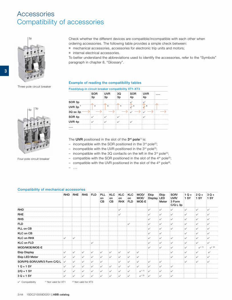
3
3p
4p 3p
3/44 1SDC210059D0201 | ABB catalog
AccessoriesCompatibility of accessories
Check whether the different devices are compatible/incompatible with each other when ordering accessories. The following table provides a simple check between: ■ mechanical accessories, accessories for electronic trip units and motors; ■ internal electrical accessories.To better understand the abbreviations used to identify the accessories, refer to the “Symbols” paragraph in chapter 8, “Glossary”.
Example of reading the compatibility tables
Fixed/plug-in circuit breaker compatibility XT1-XT3
SOR 3p
UVR 3p
3Q 3p
SOR 4p
UVR 4p
.....
SOR 3p ✔ ✔
UVR 3p 1
2
3
4
✔ 5
✔ 6
3Q sx 3p ✔ ✔
SOR 4p ✔ ✔ ✔ ✔
UVR 4p ✔ ✔ ✔ ✔
.....
The UVR positioned in the slot of the 3rd pole(1) is:– incompatible with the SOR positioned in the 3rd pole(2);– incompatible with the UVR positioned in the 3rd pole(3);– incompatible with the 3Q contacts on the left in the 3rd pole(4);– compatible with the SOR positioned in the slot of the 4th pole(5);– compatible with the UVR positioned in the slot of the 4th pole(6).– ....
Compatibility of mechanical accessories
RHD RHE RHS FLD PLL on CB
KLC on CB
KLC on RHX
KLC on FLD
MOD/MOE/MOE-E
Ekip Display
Ekip LED Meter
SOR/UVR/3 Form C/Q L 3p
1 Q + 1 SY
2 Q + 1 SY
3 Q + 1 SY
RHD ✔ ✔ ✔ ✔ ✔ ✔ ✔
RHE ✔ ✔ ✔ ✔ ✔ ✔ ✔
RHS ✔ ✔ ✔ ✔ ✔ ✔
FLD ✔ ✔ ✔ ✔ ✔ ✔ ✔
PLL on CB ✔ ✔ ✔ ✔ ✔ ✔
KLC on CB ✔ ✔ ✔ ✔ ✔
KLC on RHX ✔ ✔ ✔ ✔ ✔ ✔ ✔ ✔
KLC on FLD ✔ ✔ ✔ ✔ ✔ ✔ ✔
MOD/MOE/MOE-E ✔ ✔ ✔ ✔ ✔ (1) ✔ (2)
Ekip Display ✔ ✔ ✔ ✔ ✔ ✔ ✔ ✔ ✔ ✔ ✔ ✔ ✔
Ekip LED Meter ✔ ✔ ✔ ✔ ✔ ✔ ✔ ✔ ✔ ✔ ✔ ✔ ✔
SOR/PS-SOR/UVR/3 Form C/Q L ✔ ✔ ✔ ✔ ✔ ✔ ✔ ✔ ✔ ✔ ✔ ✔ ✔
1 Q + 1 SY ✔ ✔ ✔ ✔ ✔ ✔ ✔ ✔ ✔ ✔ ✔ ✔
2/Q + 1 SY ✔ ✔ ✔ ✔ ✔ ✔ ✔ ✔ ✔ (1) ✔ ✔ ✔
3 Q + 1 SY ✔ ✔ ✔ ✔ ✔ ✔ ✔ ✔ ✔ (2) ✔ ✔ ✔
✔ Compatibility (1) Not valid for XT1 (2) Not valid for XT3
Three-pole circuit breaker
Four-pole circuit breaker
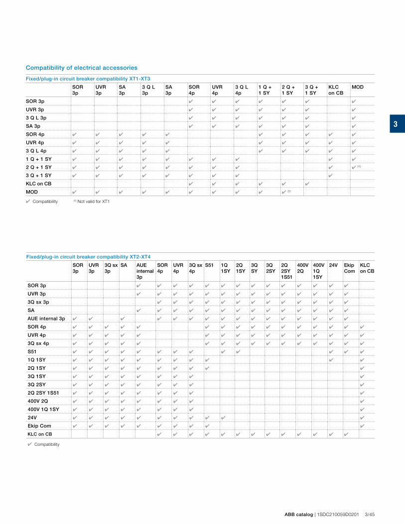
3
ABB catalog | 1SDC210059D0201 3/45
Compatibility of electrical accessories
Fixed/plug-in circuit breaker compatibility XT1-XT3
SOR 3p
UVR 3p
SA3p
3 Q L 3p
SA3p
SOR 4p
UVR4p
3 Q L 4p
1 Q + 1 SY
2 Q + 1 SY
3 Q + 1 SY
KLC on CB
MOD
SOR 3p ✔ ✔ ✔ ✔ ✔ ✔ ✔
UVR 3p ✔ ✔ ✔ ✔ ✔ ✔ ✔
3 Q L 3p ✔ ✔ ✔ ✔ ✔ ✔ ✔
SA 3p ✔ ✔ ✔ ✔ ✔ ✔ ✔
SOR 4p ✔ ✔ ✔ ✔ ✔ ✔ ✔ ✔ ✔ ✔
UVR 4p ✔ ✔ ✔ ✔ ✔ ✔ ✔ ✔ ✔ ✔
3 Q L 4p ✔ ✔ ✔ ✔ ✔ ✔ ✔ ✔ ✔ ✔
1 Q + 1 SY ✔ ✔ ✔ ✔ ✔ ✔ ✔ ✔ ✔ ✔
2 Q + 1 SY ✔ ✔ ✔ ✔ ✔ ✔ ✔ ✔ ✔ ✔ (1)
3 Q + 1 SY ✔ ✔ ✔ ✔ ✔ ✔ ✔ ✔ ✔
KLC on CB ✔ ✔ ✔ ✔ ✔ ✔
MOD ✔ ✔ ✔ ✔ ✔ ✔ ✔ ✔ ✔ ✔ (1)
✔ Compatibility (1) Not valid for XT1
Fixed/plug-in circuit breaker compatibility XT2-XT4
SOR 3p
UVR 3p
3Q sx3p
SA AUE internal 3p
SOR 4p
UVR 4p
3Q sx 4p
S51 1Q 1SY
2Q 1SY
3Q SY
3Q 2SY
2Q 2SY 1S51
400V 2Q
400V 1Q 1SY
24V Ekip Com
KLC on CB
SOR 3p ✔ ✔ ✔ ✔ ✔ ✔ ✔ ✔ ✔ ✔ ✔ ✔ ✔ ✔
UVR 3p ✔ ✔ ✔ ✔ ✔ ✔ ✔ ✔ ✔ ✔ ✔ ✔ ✔ ✔
3Q sx 3p ✔ ✔ ✔ ✔ ✔ ✔ ✔ ✔ ✔ ✔ ✔ ✔ ✔
SA ✔ ✔ ✔ ✔ ✔ ✔ ✔ ✔ ✔ ✔ ✔ ✔ ✔ ✔
AUE internal 3p ✔ ✔ ✔ ✔ ✔ ✔ ✔ ✔ ✔ ✔ ✔ ✔ ✔ ✔ ✔ ✔
SOR 4p ✔ ✔ ✔ ✔ ✔ ✔ ✔ ✔ ✔ ✔ ✔ ✔ ✔ ✔ ✔ ✔
UVR 4p ✔ ✔ ✔ ✔ ✔ ✔ ✔ ✔ ✔ ✔ ✔ ✔ ✔ ✔ ✔ ✔
3Q sx 4p ✔ ✔ ✔ ✔ ✔ ✔ ✔ ✔ ✔ ✔ ✔ ✔ ✔ ✔ ✔ ✔
S51 ✔ ✔ ✔ ✔ ✔ ✔ ✔ ✔ ✔ ✔ ✔ ✔ ✔
1Q 1SY ✔ ✔ ✔ ✔ ✔ ✔ ✔ ✔ ✔ ✔ ✔
2Q 1SY ✔ ✔ ✔ ✔ ✔ ✔ ✔ ✔ ✔ ✔
3Q 1SY ✔ ✔ ✔ ✔ ✔ ✔ ✔ ✔ ✔
3Q 2SY ✔ ✔ ✔ ✔ ✔ ✔ ✔ ✔ ✔
2Q 2SY 1S51 ✔ ✔ ✔ ✔ ✔ ✔ ✔ ✔ ✔
400V 2Q ✔ ✔ ✔ ✔ ✔ ✔ ✔ ✔ ✔
400V 1Q 1SY ✔ ✔ ✔ ✔ ✔ ✔ ✔ ✔ ✔
24V ✔ ✔ ✔ ✔ ✔ ✔ ✔ ✔ ✔ ✔ ✔
Ekip Com ✔ ✔ ✔ ✔ ✔ ✔ ✔ ✔ ✔ ✔
KLC on CB ✔ ✔ ✔ ✔ ✔ ✔ ✔ ✔ ✔ ✔ ✔ ✔ ✔
✔ Compatibility
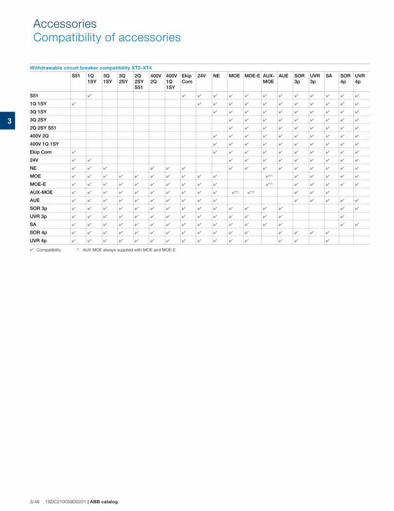
3
3/46 1SDC210059D0201 | ABB catalog
Withdrawable circuit breaker compatibility XT2-XT4
S51 1Q 1SY
3Q 1SY
3Q 2SY
2Q 2SY S51
400V 2Q
400V 1Q 1SY
Ekip Com
24V NE MOE MOE-E AUX-MOE
AUE SOR 3p
UVR 3p
SA SOR 4p
UVR 4p
S51 ✔ ✔ ✔ ✔ ✔ ✔ ✔ ✔ ✔ ✔ ✔ ✔ ✔
1Q 1SY ✔ ✔ ✔ ✔ ✔ ✔ ✔ ✔ ✔ ✔ ✔ ✔
3Q 1SY ✔ ✔ ✔ ✔ ✔ ✔ ✔ ✔ ✔ ✔
3Q 2SY ✔ ✔ ✔ ✔ ✔ ✔ ✔ ✔ ✔
2Q 2SY S51 ✔ ✔ ✔ ✔ ✔ ✔ ✔ ✔ ✔
400V 2Q ✔ ✔ ✔ ✔ ✔ ✔ ✔ ✔ ✔ ✔
400V 1Q 1SY ✔ ✔ ✔ ✔ ✔ ✔ ✔ ✔ ✔ ✔
Ekip Com ✔ ✔ ✔ ✔ ✔ ✔ ✔ ✔ ✔ ✔ ✔
24V ✔ ✔ ✔ ✔ ✔ ✔ ✔ ✔ ✔ ✔ ✔
NE ✔ ✔ ✔ ✔ ✔ ✔ ✔ ✔ ✔ ✔ ✔ ✔ ✔ ✔ ✔
MOE ✔ ✔ ✔ ✔ ✔ ✔ ✔ ✔ ✔ ✔ ✔ (1) ✔ ✔ ✔ ✔ ✔
MOE-E ✔ ✔ ✔ ✔ ✔ ✔ ✔ ✔ ✔ ✔ ✔(1) ✔ ✔ ✔ ✔ ✔
AUX-MOE ✔ ✔ ✔ ✔ ✔ ✔ ✔ ✔ ✔ ✔ ✔(1) ✔(1) ✔ ✔ ✔
AUE ✔ ✔ ✔ ✔ ✔ ✔ ✔ ✔ ✔ ✔ ✔ ✔ ✔ ✔ ✔
SOR 3p ✔ ✔ ✔ ✔ ✔ ✔ ✔ ✔ ✔ ✔ ✔ ✔ ✔ ✔ ✔ ✔
UVR 3p ✔ ✔ ✔ ✔ ✔ ✔ ✔ ✔ ✔ ✔ ✔ ✔ ✔ ✔ ✔
SA ✔ ✔ ✔ ✔ ✔ ✔ ✔ ✔ ✔ ✔ ✔ ✔ ✔ ✔ ✔ ✔
SOR 4p ✔ ✔ ✔ ✔ ✔ ✔ ✔ ✔ ✔ ✔ ✔ ✔ ✔ ✔ ✔ ✔
UVR 4p ✔ ✔ ✔ ✔ ✔ ✔ ✔ ✔ ✔ ✔ ✔ ✔ ✔ ✔ ✔
✔ Compatibility (1) AUX-MOE always supplied with MOE and MOE-E
AccessoriesCompatibility of accessories
4
ABB catalog | 1SDC210059D0201 4/1
Characteristic curves and technical information
Characteristic curves
Examples of curve reading 4/2
Trip curves with thermomagnetic trip unit
Trip curves for distribution 4/4
Trip curves for motor protection 4/10
Trip curves with electronic trip unit
Trip curves for distribution 4/11
Trip curves for motor protection 4/15
Specific let-through energy curves
480V 4/16
600V 4/18
Limiting curves
480V 4/20
600V 4/22
Technical information
Temperature performances 4/24
Dissipated powers 4/28
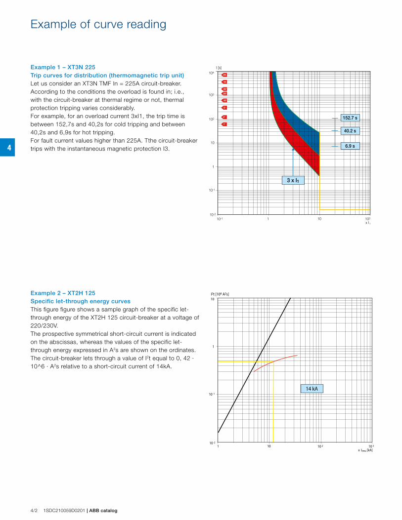
4
Example of curve reading
t [s]
x I110
10-1
10-2
102
1
10
102
103
104
110-1
152.7 s
40.2 s
6.9 s
3 x I1
I2t [106 A2s]
x Irms [kA]10
10-1
10-2
1
10
1 10 2 10 3
14 kA
4/2 1SDC210059D0201 | ABB catalog
Example 1 – XT3N 225Trip curves for distribution (thermomagnetic trip unit)Let us consider an XT3N TMF In = 225A circuit-breaker.According to the conditions the overload is found in; i.e., with the circuit-breaker at thermal regime or not, thermal protection tripping varies considerably.For example, for an overload current 3xI1, the trip time is between 152,7s and 40,2s for cold tripping and between 40,2s and 6,9s for hot tripping.For fault current values higher than 225A. Tthe circuit-breaker trips with the instantaneous magnetic protection I3.
Example 2 – XT2H 125Specific let-through energy curvesThis figure figure shows a sample graph of the specific let-through energy of the XT2H 125 circuit-breaker at a voltage of 220/230V.The prospective symmetrical short-circuit current is indicated on the abscissas, whereas the values of the specific let-through energy expressed in A2s are shown on the ordinates.The circuit-breaker lets through a value of I2t equal to 0, 42 · 10^6 · A2s relative to a short-circuit current of 14kA.
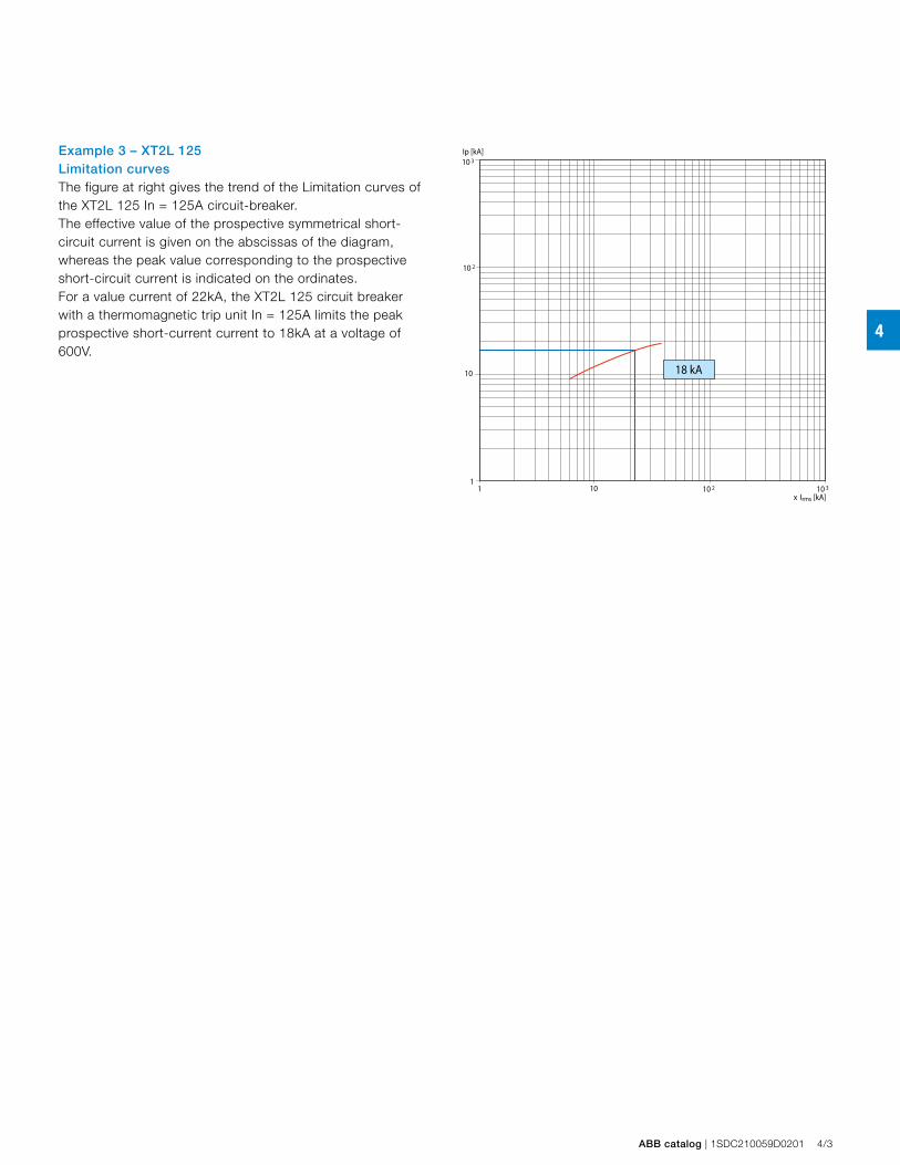
4
Ip [kA]
x Irms [kA]10
10
11 10 2 10 3
10 2
10 3
18 kA
ABB catalog | 1SDC210059D0201 4/3
Example 3 – XT2L 125Limitation curvesThe figure at right gives the trend of the Limitation curves of the XT2L 125 In = 125A circuit-breaker.The effective value of the prospective symmetrical short-circuit current is given on the abscissas of the diagram, whereas the peak value corresponding to the prospective short-circuit current is indicated on the ordinates.For a value current of 22kA, the XT2L 125 circuit breaker with a thermomagnetic trip unit In = 125A limits the peak prospective short-current current to 18kA at a voltage of 600V.
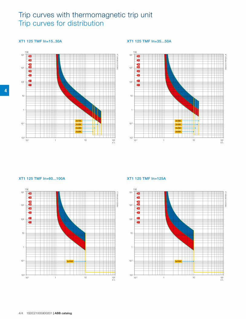
4
Trip curves with thermomagnetic trip unitTrip curves for distribution
XT1 125 TMF In=15..30A
t [s]
x I110
10-1
10-2
102
1
10
102
103
104
110-1
In=30A
In=25A
In=20A
In=15A
1SD
C21
017E
F000
1_A
XT1 125 TMF In=125A
t [s]
x I110
10-1
10-2
102
1
10
102
103
104
110-1
I3=10xIn
1SD
C21
017E
F000
1_D
XT1 125 TMF In=35...50A
t [s]
x I110
10-1
10-2
102
1
10
102
103
104
110-1
In=50A
In=45A
In=40A
In=35A
1SD
C21
017E
F000
1_B
XT1 125 TMF In=60...100A
t [s]
x I110
10-1
10-2
102
1
10
102
103
104
110-1
I3=10xIn
1SD
C21
017E
F000
1_C
4/4 1SDC210059D0201 | ABB catalog
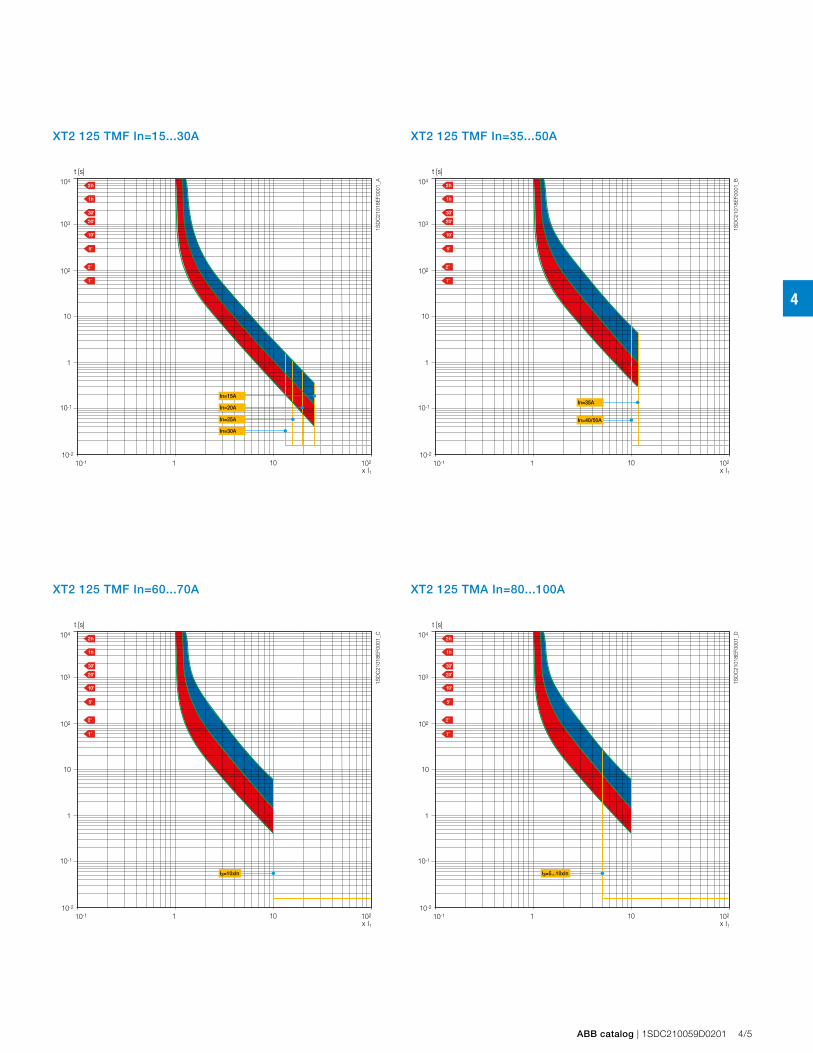
4
XT2 125 TMF In=15...30A
t [s]
x I110
10-1
10-2
102
1
10
102
103
104
110-1
In=30A
In=25A
In=20A
In=15A
1SD
C21
018E
F000
1_A
XT2 125 TMF In=35...50A
t [s]
x I110
10-1
10-2
102
1
10
102
103
104
110-1
In=40/50A
In=35A
1SD
C21
018E
F000
1_B
XT2 125 TMF In=60...70A
t [s]
x I110
10-1
10-2
102
1
10
102
103
104
110-1
I3=10xIn
1SD
C21
018E
F000
1_C
XT2 125 TMA In=80...100A
t [s]
x I110
10-1
10-2
102
1
10
102
103
104
110-1
I3=5...10xIn
1SD
C21
018E
F000
1_D
ABB catalog | 1SDC210059D0201 4/5
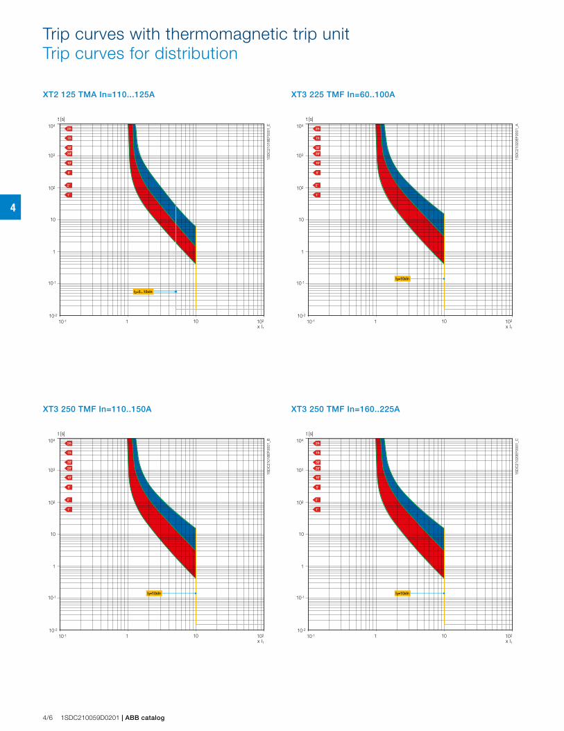
4
Trip curves with thermomagnetic trip unitTrip curves for distribution
XT2 125 TMA In=110...125A
t [s]
x I110
10-1
10-2
102
1
10
102
103
104
110-1
I3=5...10xIn
1SD
C21
018E
F000
1_E
XT3 225 TMF In=60..100A
t [s]
x I110
10-1
10-2
102
1
10
102
103
104
110-1
I3=10xIn
1SD
C21
020E
F000
1_A
XT3 250 TMF In=110..150A
t [s]
x I110
10-1
10-2
102
1
10
102
103
104
110-1
I3=10xIn
1SD
C21
018E
F000
1_B
XT3 250 TMF In=160..225A
t [s]
x I110
10-1
10-2
102
1
10
102
103
104
110-1
I3=10xIn
1SD
C21
020E
F000
1_C
4/6 1SDC210059D0201 | ABB catalog
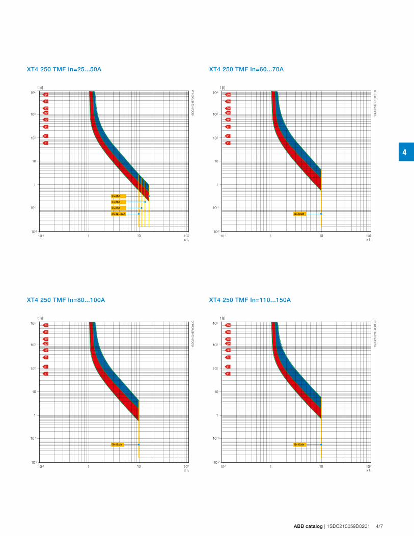
4
t [s]
x I110
10-1
10-2
102
1
10
102
103
104
110-1
In=25A
In=40...50A
In=35A
In=30A
1SD
C21
021E
F000
1_A
XT4 250 TMF In=25...50A
t [s]
x I110
10-1
10-2
102
1
10
102
103
104
110-1
I3=10xIn
1SD
C21
021E
F000
1_B
XT4 250 TMF In=60...70A
t [s]
x I110
10-1
10-2
102
1
10
102
103
104
110-1
I3=10xIn
1SD
C21
021E
F000
1_C
XT4 250 TMF In=80...100A
t [s]
x I110
10-1
10-2
102
1
10
102
103
104
110-1
I3=10xIn
1SD
C21
021E
F000
1_C
XT4 250 TMF In=110...150A
ABB catalog | 1SDC210059D0201 4/7
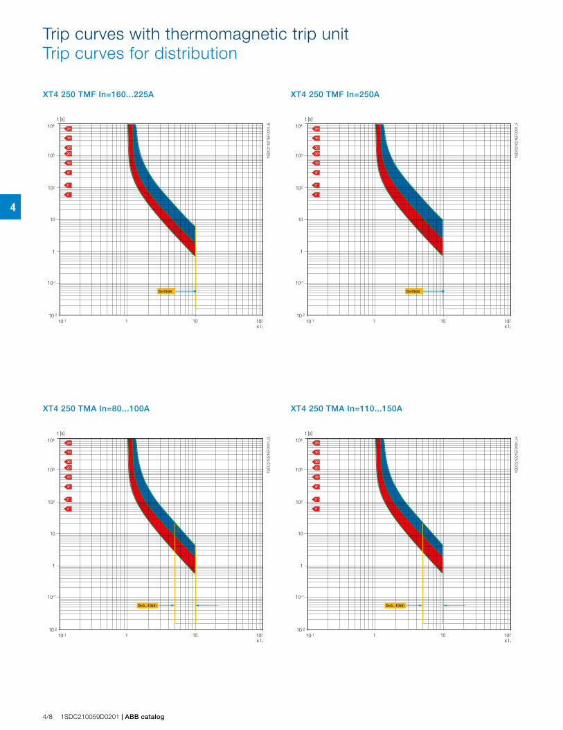
4
Trip curves with thermomagnetic trip unitTrip curves for distribution
t [s]
x I110
10-1
10-2
102
1
10
102
103
104
110-1
I3=10xIn
1SD
C21
021E
F000
1_E
XT4 250 TMF In=160...225A
t [s]
x I110
10-1
10-2
102
1
10
102
103
104
110-1
I3=10xIn
1SD
C21
021E
F000
1_F
XT4 250 TMF In=250A
t [s]
x I110
10-1
10-2
102
1
10
102
103
104
110-1
I3=5...10xIn
1SD
C21
021E
F000
1_G
XT4 250 TMA In=80...100A
t [s]
x I110
10-1
10-2
102
1
10
102
103
104
110-1
I3=5...10xIn
1SD
C21
021E
F000
1_H
XT4 250 TMA In=110...150A
4/8 1SDC210059D0201 | ABB catalog
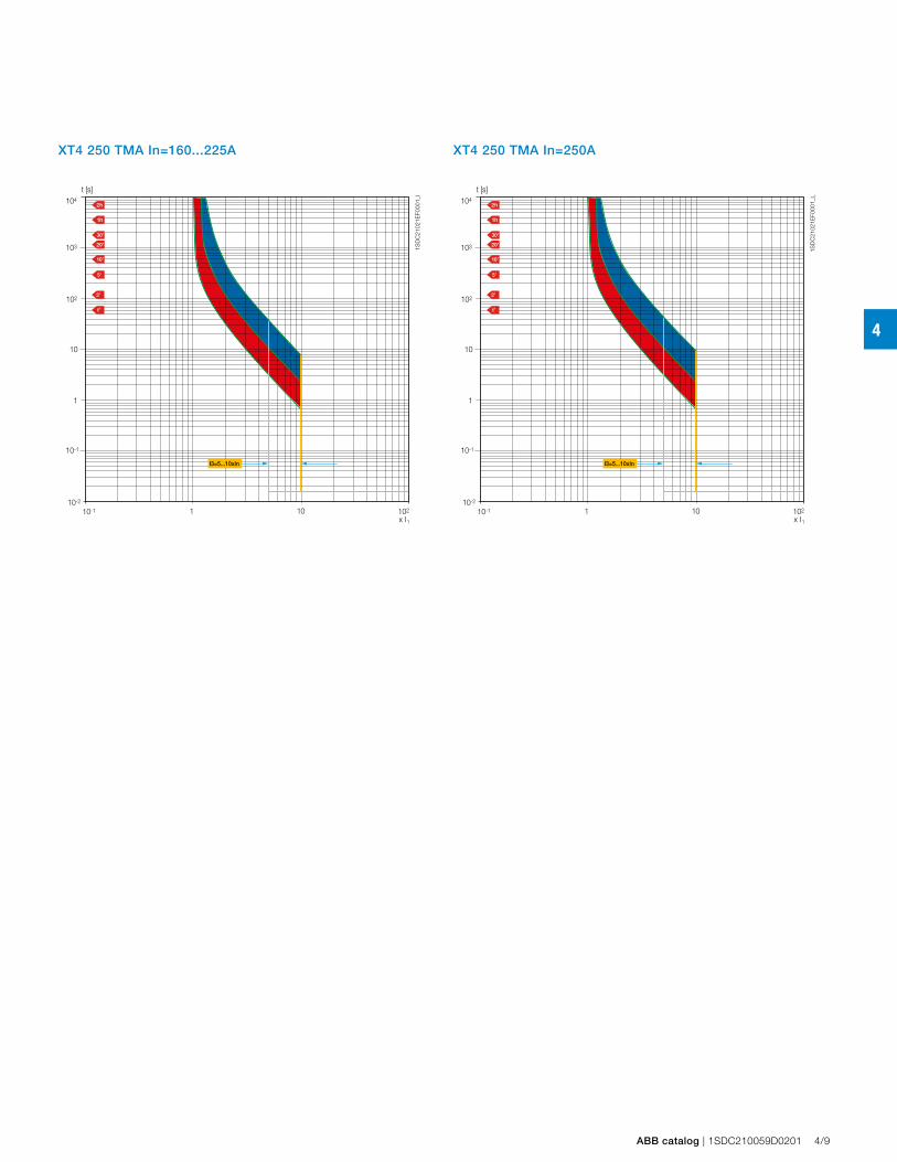
4
t [s]
x I110
10-1
10-2
102
1
10
102
103
104
110-1
I3=5...10xIn
1SD
C21
021E
F000
1_I
XT4 250 TMA In=160...225A
t [s]
x I110
10-1
10-2
102
1
10
102
103
104
110-1
I3=5...10xIn
1SD
C21
021E
F000
1_L
XT4 250 TMA In=250A
ABB catalog | 1SDC210059D0201 4/9
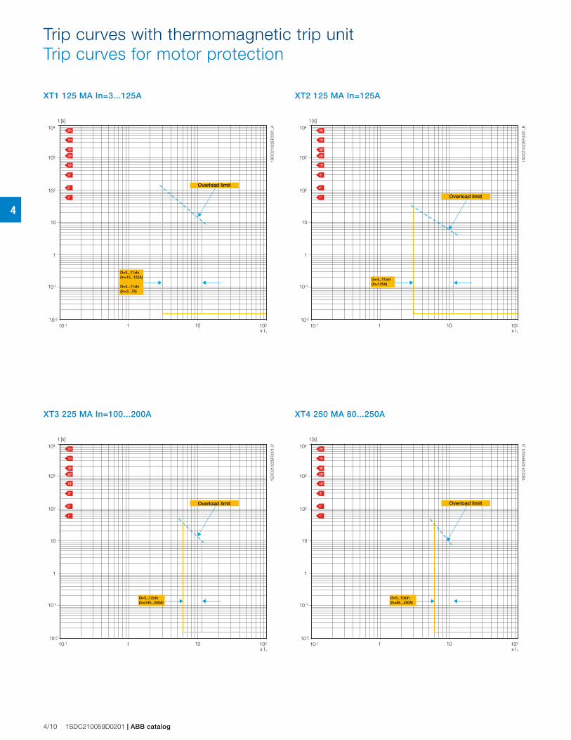
4
Trip curves with thermomagnetic trip unitTrip curves for motor protection
XT1 125 MA In=3...125A
t [s]
x I110
10-1
10-2
102
1
10
102
103
104
110-1
I3=3...11xIn(In=15...125A)
I3=4...11xIn(In=3...7A)
1SD
C21
022E
F000
1_A
XT2 125 MA In=125A
t [s]
x I110
10-1
10-2
102
1
10
102
103
104
110-1
I3=4...11xIn(In=125A)
1SD
C21
022E
F000
1_B
XT3 225 MA In=100...200A
t [s]
x I110
10-1
10-2
102
1
10
102
103
104
110-1
I3=3...12xIn(In=100...200A)
1SD
C21
022E
F000
1_C
XT4 250 MA 80...250A
t [s]
x I110
10-1
10-2
102
1
10
102
103
104
110-1
I3=5...10xIn(In=80...250A)
1SD
C21
022E
F000
1_D
4/10 1SDC210059D0201 | ABB catalog
Overload limit
Overload limit
Overload limit Overload limit
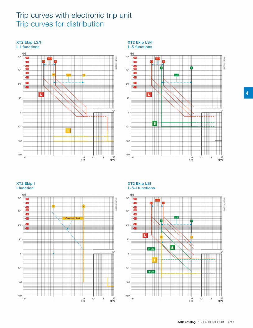
4
Trip curves with electronic trip unitTrip curves for distribution
XT2 Ekip LS/I L-I functions
XT2 Ekip LS/I L-S functions
XT2 Ekip I I function
XT2 Ekip LSI L-S-I functions
t [s]
x In10
10 -1
10 -2
10-3
1
10
10 2
10 3
10 4
110-1
I [kA]10
102
110-1
1...10 10
1
0.4...1
0.4
1
t [s]
10
10 -1
10 -2
10-3
1
10
10 2
10 3
10 4
110-1
x In I [kA]10
102
110-1
1...10
1
0.4...1
0.4
1 10
t [s]
10
10 -1
10 -2
10-3
1
10
10 2
10 3
10 4
110-1
x In I [kA]10
102
110-1
101
t [s]
10
10 -1
10 -2
10-3
1
10
10 2
10 3
10 4
110-1
x In I [kA]10
102
110-1
1
0.4...1
0.4
1...10
101
1 10
I2t ON
I2t OFF
1SD
C21
011G
F000
1
1SD
C21
012G
F000
1
1SD
C21
013G
F000
1
1SD
C21
014G
F000
1
ABB catalog | 1SDC210059D0201 4/11
Overload limit
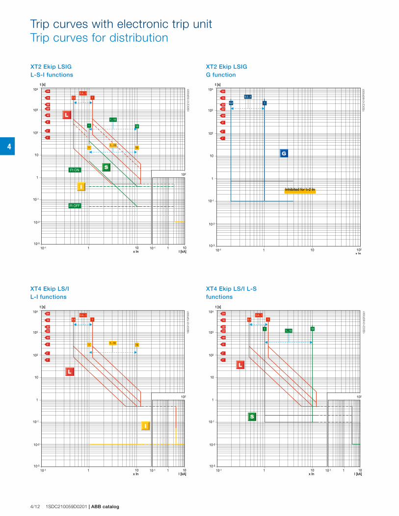
4
Trip curves with electronic trip unitTrip curves for distribution
t [s]
10
10 -1
10 -2
10-3
1
10
10 2
10 3
10 4
110-1
x In I [kA]10
102
110-1
1
0.4...1
0.4
I2t ON
I2t OFF
101
1 10
1...10
1...10
t [s]
10
10 -1
10 -2
10-3
1
10
10 2
10 3
10 4
110-1
x In102
10.2
0.2...1
t [s]
10
10 -1
10 -2
10-3
1
10
10 2
10 3
10 4
110-1
x In I [kA]10
102
110-1
10
1
0.4...1
0.4
11...10
t [s]
10
10 -1
10 -2
10-3
1
10
10 2
10 3
10 4
110-1
x In I [kA]10
102
110-1
1...10
1
0.4...1
0.4
1 10
1SD
C21
015G
F000
1
1SD
C21
016G
F000
1
1SD
C21
017G
F000
1
1SD
C21
018G
F000
1
4/12 1SDC210059D0201 | ABB catalog
XT2 Ekip LSIG G function
XT2 Ekip LSIG L-S-I functions
XT4 Ekip LS/I L-S functions
XT4 Ekip LS/I L-I functions
Inhibited for I>2 In
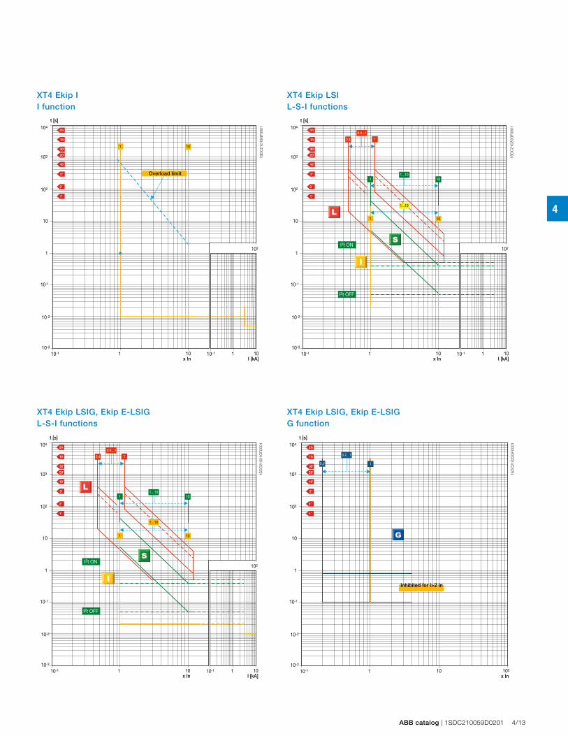
4
t [s]
10
10 -1
10 -2
10-3
1
10
10 2
10 3
10 4
110-1
x In I [kA]10
102
110-1
101
t [s]
10
10 -1
10 -2
10-3
1
10
10 2
10 3
10 4
110-1
x In I [kA]10
102
110-1
1
0.4...1
0.4
101
1 10
I2t ON
I2t OFF
1...10
1...10
t [s]
10
10 -1
10 -2
10-3
1
10
10 2
10 3
10 4
110-1
x In I [kA]10
102
110-1
1
0.4...1
0.4
1...10
1...10
101
1 10
I2t ON
I2t OFF
1SD
C21
019G
F000
1
1SD
C21
020G
F000
1
1SD
C21
021G
F000
1
t [s]
10
10 -1
10 -2
10-3
1
10
10 2
10 3
10 4
110-1
x In102
10.2
0.2...1
1SD
C21
022G
F000
1
ABB catalog | 1SDC210059D0201 4/13
XT4 Ekip LSIG, Ekip E-LSIG G function
XT4 Ekip I I function
XT4 Ekip LSI L-S-I functions
XT4 Ekip LSIG, Ekip E-LSIG L-S-I functions
Overload limit
Inhibited for I>2 In
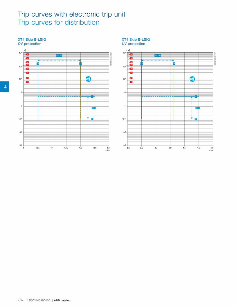
4
Trip curves with electronic trip unitTrip curves for distribution
t [s]
1.2
10-1
10-2
10-3
1
10
102
103
104
1.11x Un
1.31.151.05 1.25
1.21.05
1.05...1.2
0.1
5
0.1...5
t [s]
1.1
10-1
10-2
10-3
1
10
102
103
104
0.70.3x Un
1.50.90.5 1.3
0.5...0.95
0.1
5
0.1...5
0.950.5
1SD
C21
034G
F000
1
1SD
C21
035G
F000
1
4/14 1SDC210059D0201 | ABB catalog
XT4 Ekip E-LSIGUV protection
XT4 Ekip E-LSIGOV protection
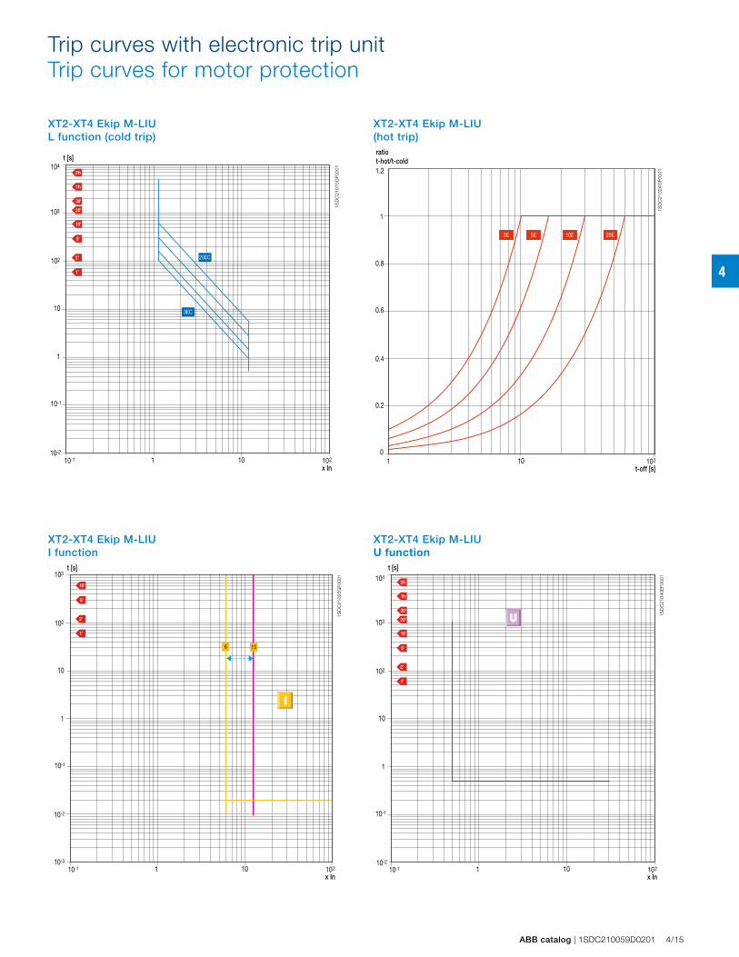
4
Trip curves with electronic trip unitTrip curves for motor protection
t [s]
x In10
10-1
10-2
10-3
1
10
102
103
110-1 102
136
ratiot-hot/t-cold
t-off [s]10
1.2
1
0.8
0.6
0.4
0.2
01 102
20E10E5E3E
1SD
C21
070G
F000
1
1SD
C21
024G
F000
1
1SD
C21
025G
F000
1
t [s]
x In10
10-1
10-2
1
10
102
103
104
110-1 102
20EC
3EC
t [s]
x In10
10 -1
10-2
1
10
10 2
10 3
10 4
110-1 102
1SD
C21
040E
F000
1
ABB catalog | 1SDC210059D0201 4/15
XT2-XT4 Ekip M-LIUL function (cold trip)
XT2-XT4 Ekip M-LIU(hot trip)
XT2-XT4 Ekip M-LIUI function
XT2-XT4 Ekip M-LIUU function
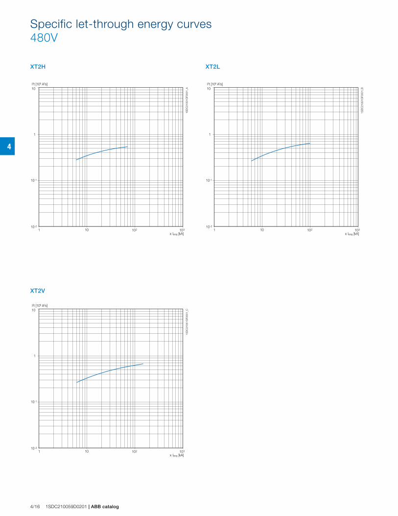
4
XT2H XT2L
XT2V
I2t [106 A2s]
x Irms [kA]101 102 103
1
10
10-2
10-1
1SD
C21
051G
F000
1_A
I2t [106 A2s]
x Irms [kA]101 102 103
1
10
10-2
10-1
1SD
C21
051G
F000
1_B
I2t [106 A2s]
x Irms [kA]101 102 103
1
10
10-2
10-1
1SD
C21
051G
F000
1_C
4/16 1SDC210059D0201 | ABB catalog
Specific let-through energy curves480V

4
XT4H XT4L
XT4V
I2t [106 A2s]
x Irms [kA]101 102 103
1
10
10-2
10-11S
DC
2105
1GF0
001_
G
I2t [106 A2s]
x Irms [kA]101 102 103
1
10
10-2
10-1
1SD
C21
051G
F000
1_H
I2t [106 A2s]
x Irms [kA]101 102 103
1
10
10-2
10-1
1SD
C21
051G
F000
1_I
ABB catalog | 1SDC210059D0201 4/17

4
XT2H XT2L
XT2V
I2t [106 A2s]
x Irms [kA]101 102 103
1
10
10-2
10-1
1SD
C21
051G
F000
1_D
I2t [106 A2s]
x Irms [kA]101 102 103
1
10
10-2
10-1
1SD
C21
051G
F000
1_E
I2t [106 A2s]
x Irms [kA]101 102 103
1
10
10-2
10-1
1SD
C21
051G
F000
1_F
4/18 1SDC210059D0201 | ABB catalog
Specific let-through energy curves600V

4
XT4H XT4L
XT4V
I2t [106 A2s]
x Irms [kA]101 102 103
1
10
10-2
10-11S
DC
2105
1GF0
001_
L
I2t [106 A2s]
x Irms [kA]101 102 103
1
10
10-2
10-1
1SD
C21
051G
F000
1_M
I2t [106 A2s]
x Irms [kA]101 102 103
1
10
10-2
10-1
1SD
C21
051G
F000
1_N
ABB catalog | 1SDC210059D0201 4/19
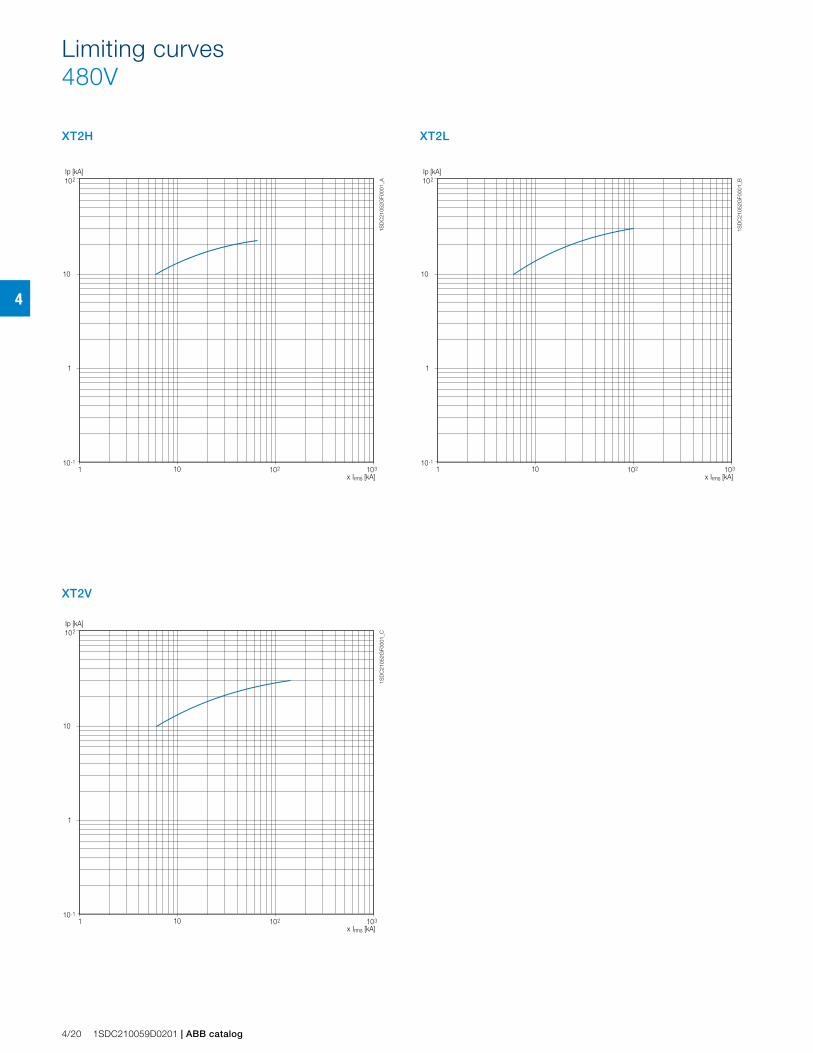
4
XT2H XT2L
XT2V
Ip [kA]
x Irms [kA]101 102 103
10
10-1
1
2
10
1SD
C21
052G
F000
1_A
Ip [kA]
x Irms [kA]101 102 103
10
10-1
1
2
10
1SD
C21
052G
F000
1_B
Ip [kA]
x Irms [kA]101 102 103
10
10-1
1
2
10
1SD
C21
052G
F000
1_C
4/20 1SDC210059D0201 | ABB catalog
Limiting curves480V

4
XT4H XT4L
XT4V
Ip [kA]
x Irms [kA]101 102 103
10
10-1
1
2
10
1SD
C21
052G
F000
1_G
Ip [kA]
x Irms [kA]101 102 103
10
10-1
1
2
10
1SD
C21
052G
F000
1_H
Ip [kA]
x Irms [kA]101 102 103
10
10-1
1
2
10
1SD
C21
052G
F000
1_I
ABB catalog | 1SDC210059D0201 4/21
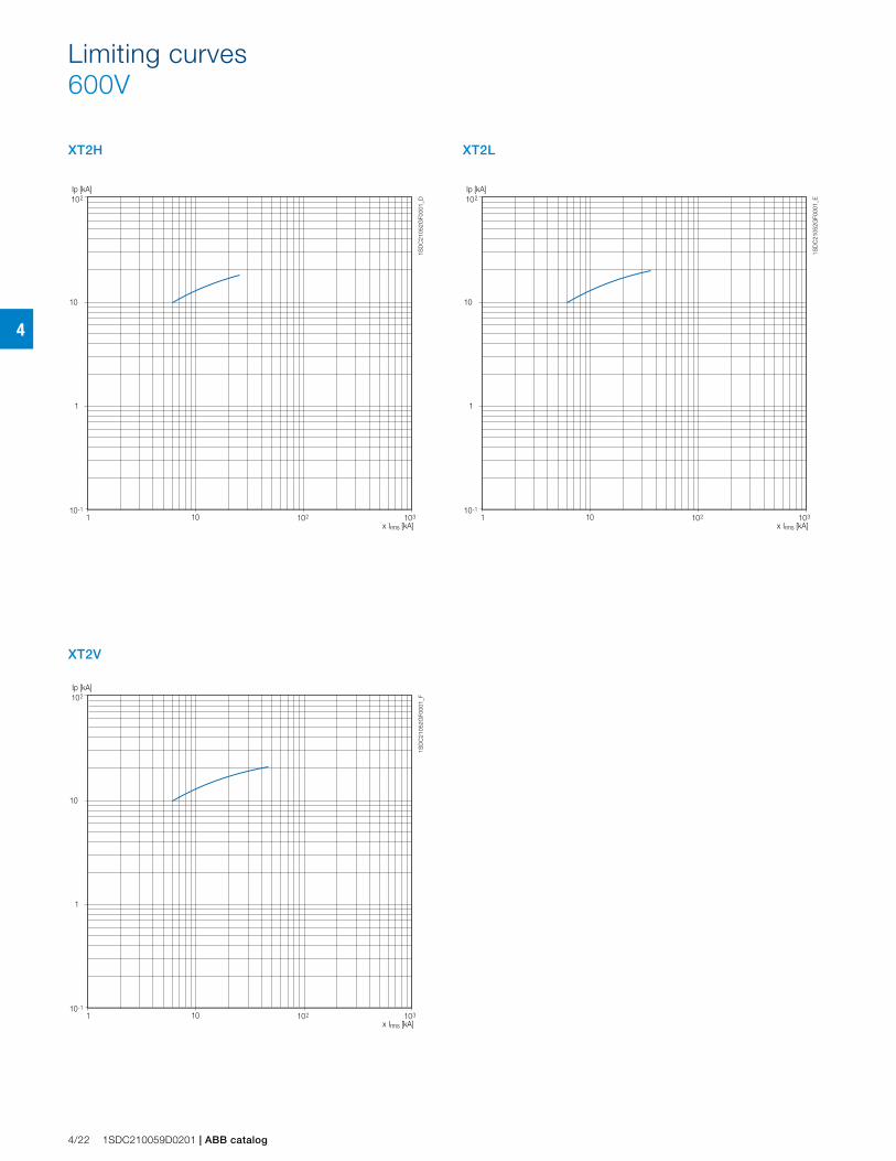
4
XT2H XT2L
XT2V
Ip [kA]
x Irms [kA]101 102 103
10
10-1
1
2
10
1SD
C21
052G
F000
1_D
Ip [kA]
x Irms [kA]101 102 103
10
10-1
1
2
10
1SD
C21
052G
F000
1_E
Ip [kA]
x Irms [kA]101 102 103
10
10-1
1
2
10
1SD
C21
052G
F000
1_F
4/22 1SDC210059D0201 | ABB catalog
Limiting curves600V
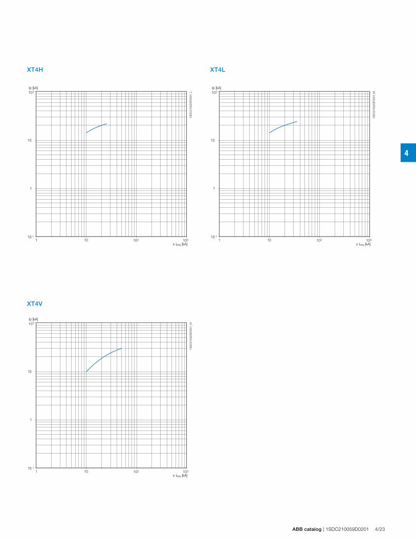
4
XT4H XT4L
XT4V
Ip [kA]
x Irms [kA]101 102 103
10
10-1
1
2
10
1SD
C21
052G
F000
1_L
Ip [kA]
x Irms [kA]101 102 103
10
10-1
1
2
10
1SD
C21
052G
F000
1_M
Ip [kA]
x Irms [kA]101 102 103
10
10-1
1
2
10
1SD
C21
052G
F000
1_N
ABB catalog | 1SDC210059D0201 4/23
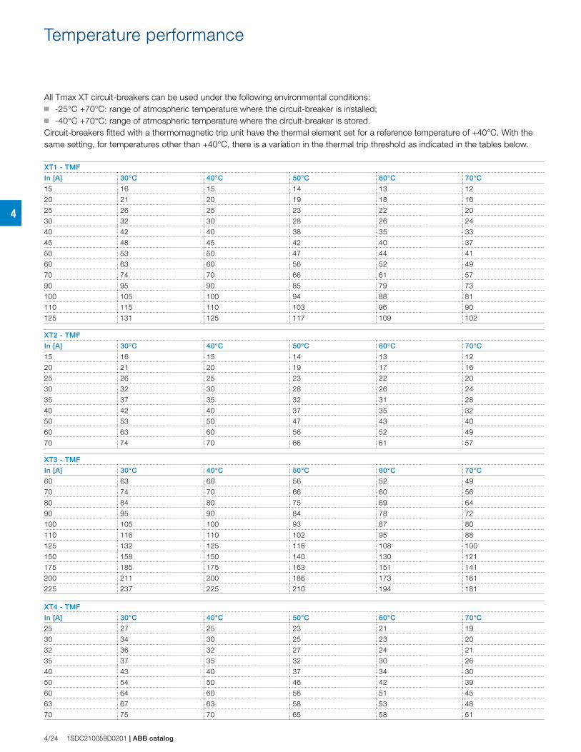
4
4/24 1SDC210059D0201 | ABB catalog
Temperature performance
All Tmax XT circuit-breakers can be used under the following environmental conditions: ■ -25°C +70°C: range of atmospheric temperature where the circuit-breaker is installed; ■ -40°C +70°C: range of atmospheric temperature where the circuit-breaker is stored.Circuit-breakers fitted with a thermomagnetic trip unit have the thermal element set for a reference temperature of +40°C. With the same setting, for temperatures other than +40°C, there is a variation in the thermal trip threshold as indicated in the tables below.
XT1 - TMF
In [A] 30°C 40°C 50°C 60°C 70°C
15 16 15 14 13 12
20 21 20 19 18 16
25 26 25 23 22 20
30 32 30 28 26 24
40 42 40 38 35 33
45 48 45 42 40 37
50 53 50 47 44 41
60 63 60 56 52 49
70 74 70 66 61 57
90 95 90 85 79 73
100 105 100 94 88 81
110 115 110 103 96 90
125 131 125 117 109 102
XT2 - TMF
In [A] 30°C 40°C 50°C 60°C 70°C
15 16 15 14 13 12
20 21 20 19 17 16
25 26 25 23 22 20
30 32 30 28 26 24
35 37 35 32 31 28
40 42 40 37 35 32
50 53 50 47 43 40
60 63 60 56 52 49
70 74 70 66 61 57
XT3 - TMF
In [A] 30°C 40°C 50°C 60°C 70°C
60 63 60 56 52 49
70 74 70 66 60 56
80 84 80 75 69 64
90 95 90 84 78 72
100 105 100 93 87 80
110 116 110 102 95 88
125 132 125 116 108 100
150 158 150 140 130 121
175 185 175 163 151 141
200 211 200 186 173 161
225 237 225 210 194 181
XT4 - TMF
In [A] 30°C 40°C 50°C 60°C 70°C
25 27 25 23 21 19
30 34 30 25 23 20
32 36 32 27 24 21
35 37 35 32 30 26
40 43 40 37 34 30
50 54 50 46 42 39
60 64 60 56 51 45
63 67 63 58 53 48
70 75 70 65 58 51
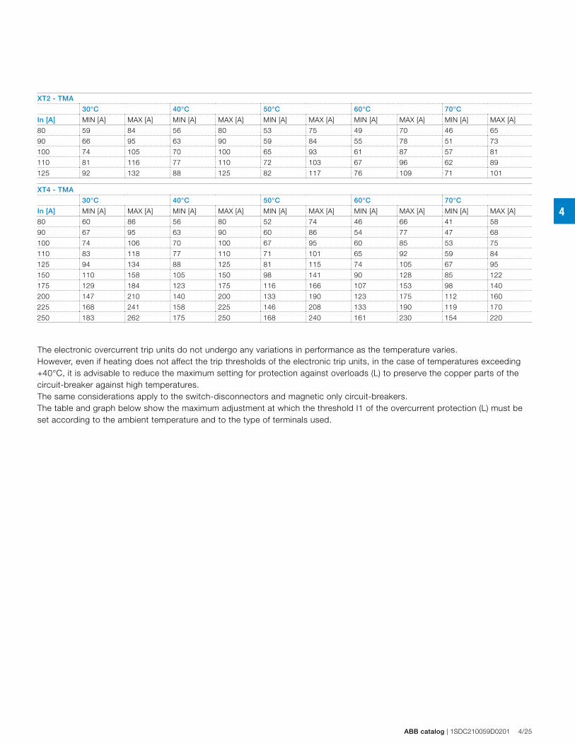
4
ABB catalog | 1SDC210059D0201 4/25
XT2 - TMA
30°C 40°C 50°C 60°C 70°C
In [A] MIN [A] MAX [A] MIN [A] MAX [A] MIN [A] MAX [A] MIN [A] MAX [A] MIN [A] MAX [A]
80 59 84 56 80 53 75 49 70 46 65
90 66 95 63 90 59 84 55 78 51 73
100 74 105 70 100 65 93 61 87 57 81
110 81 116 77 110 72 103 67 96 62 89
125 92 132 88 125 82 117 76 109 71 101
XT4 - TMA
30°C 40°C 50°C 60°C 70°C
In [A] MIN [A] MAX [A] MIN [A] MAX [A] MIN [A] MAX [A] MIN [A] MAX [A] MIN [A] MAX [A]
80 60 86 56 80 52 74 46 66 41 58
90 67 95 63 90 60 86 54 77 47 68
100 74 106 70 100 67 95 60 85 53 75
110 83 118 77 110 71 101 65 92 59 84
125 94 134 88 125 81 115 74 105 67 95
150 110 158 105 150 98 141 90 128 85 122
175 129 184 123 175 116 166 107 153 98 140
200 147 210 140 200 133 190 123 175 112 160
225 168 241 158 225 146 208 133 190 119 170
250 183 262 175 250 168 240 161 230 154 220
The electronic overcurrent trip units do not undergo any variations in performance as the temperature varies.However, even if heating does not affect the trip thresholds of the electronic trip units, in the case of temperatures exceeding +40°C, it is advisable to reduce the maximum setting for protection against overloads (L) to preserve the copper parts of the circuit-breaker against high temperatures.The same considerations apply to the switch-disconnectors and magnetic only circuit-breakers.The table and graph below show the maximum adjustment at which the threshold I1 of the overcurrent protection (L) must be set according to the ambient temperature and to the type of terminals used.
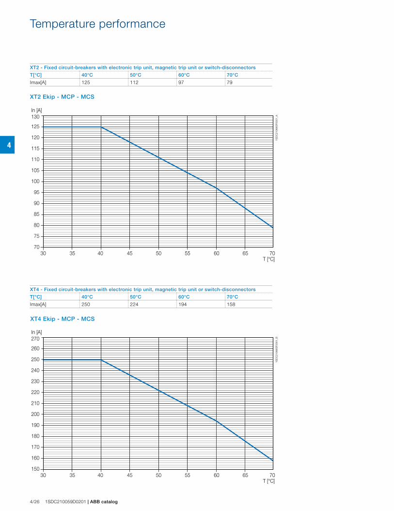
4
In [A]130
125
120
115
110
105
100
95
90
85
80
75
70
T [°C]30 35 40 45 50 55 60 65 70
1SD
C21
068G
F000
1_A
In [A]270
260
250
240
230
220
210
200
190
180
170
160
150
T [°C]30 35 40 45 50 55 60 65 70
1SD
C21
068G
F000
1_B
XT4 Ekip - MCP - MCS
XT2 Ekip - MCP - MCS
4/26 1SDC210059D0201 | ABB catalog
Temperature performance
XT2 - Fixed circuit-breakers with electronic trip unit, magnetic trip unit or switch-disconnectors
T[°C] 40°C 50°C 60°C 70°C
Imax[A] 125 112 97 79
XT4 - Fixed circuit-breakers with electronic trip unit, magnetic trip unit or switch-disconnectors
T[°C] 40°C 50°C 60°C 70°C
Imax[A] 250 224 194 158
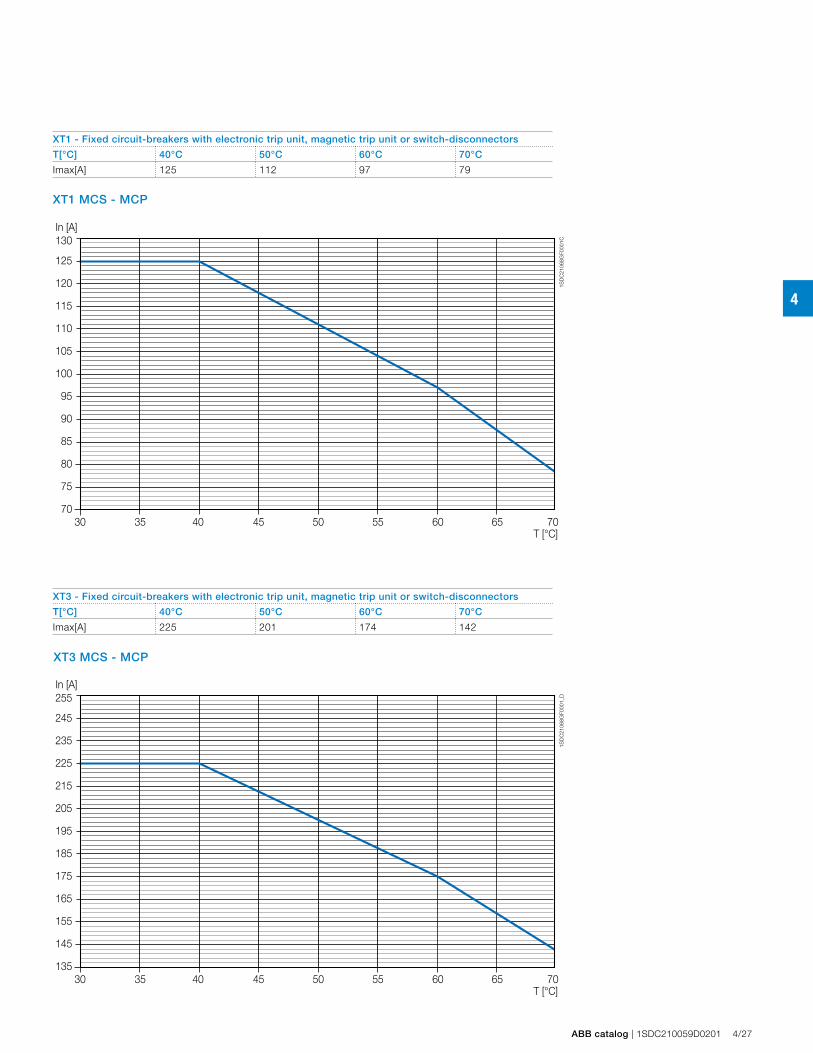
4
In [A]130
125
120
115
110
105
100
95
90
85
80
75
70
T [°C]30 35 40 45 50 55 60 65 70
1SD
C21
068G
F000
1C
In [A]255
245
235
225
215
205
195
185
175
165
155
145
135
T [°C]30 35 40 45 50 55 60 65 70
1SD
C21
068G
F000
1_D
XT3 MCS - MCP
XT1 MCS - MCP
ABB catalog | 1SDC210059D0201 4/27
XT1 - Fixed circuit-breakers with electronic trip unit, magnetic trip unit or switch-disconnectors
T[°C] 40°C 50°C 60°C 70°C
Imax[A] 125 112 97 79
XT3 - Fixed circuit-breakers with electronic trip unit, magnetic trip unit or switch-disconnectors
T[°C] 40°C 50°C 60°C 70°C
Imax[A] 225 201 174 142
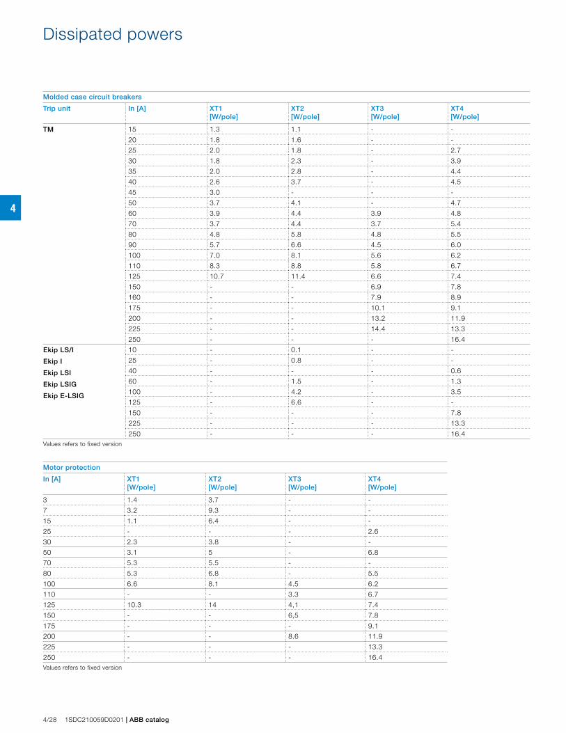
4
4/28 1SDC210059D0201 | ABB catalog
Dissipated powers
Molded case circuit breakers
Trip unit In [A] XT1 [W/pole]
XT2 [W/pole]
XT3 [W/pole]
XT4 [W/pole]
TM 15 1.3 1.1 - -
20 1.8 1.6 - -
25 2.0 1.8 - 2.7
30 1.8 2.3 - 3.9
35 2.0 2.8 - 4.4
40 2.6 3.7 - 4.5
45 3.0 - - -
50 3.7 4.1 - 4.7
60 3.9 4.4 3.9 4.8
70 3.7 4.4 3.7 5.4
80 4.8 5.8 4.8 5.5
90 5.7 6.6 4.5 6.0
100 7.0 8.1 5.6 6.2
110 8.3 8.8 5.8 6.7
125 10.7 11.4 6.6 7.4
150 - - 6.9 7.8
160 - - 7.9 8.9
175 - - 10.1 9.1
200 - - 13.2 11.9
225 - - 14.4 13.3
250 - - - 16.4
Ekip LS/I
Ekip I
Ekip LSI
Ekip LSIG
Ekip E-LSIG
10 - 0.1 - -
25 - 0.8 - -
40 - - - 0.6
60 - 1.5 - 1.3
100 - 4.2 - 3.5
125 - 6.6 - -
150 - - - 7.8
225 - - - 13.3
250 - - - 16.4Values refers to fixed version
Motor protection
In [A] XT1 [W/pole]
XT2 [W/pole]
XT3 [W/pole]
XT4 [W/pole]
3 1.4 3.7 - -
7 3.2 9.3 - -
15 1.1 6.4 - -
25 - - - 2.6
30 2.3 3.8 - -
50 3.1 5 - 6.8
70 5.3 5.5 - -
80 5.3 6.8 - 5.5
100 6.6 8.1 4.5 6.2
110 - - 3.3 6.7
125 10.3 14 4,1 7.4
150 - - 6,5 7.8
175 - - - 9.1
200 - - 8.6 11.9
225 - - - 13.3
250 - - - 16.4Values refers to fixed version