Embed Size (px)
Citation preview
1 WWW.ALLFASTENERS.COM.AUCall 1800 255 349
Revi
sed
Doc.
22.
02.2
016
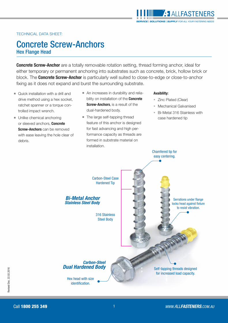
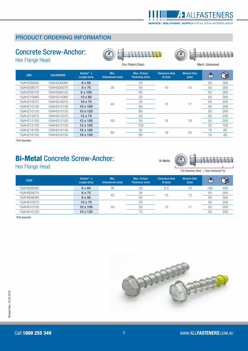
Concrete Screw-AnchorsHex Flange Head
Bi-Metal Anchor Stainless Steel Body
Chamfered tip for easy centering.
Serrations under flange locks head against fixture
to resist vibration.
Self-tapping threads designed for increased load capacity.
Hex head with size identification.
TECHNICAL DATA SHEET:
Carbon-Steel Case Hardened Tip
316 Stainless Steel Body
Concrete Screw-Anchor are a totally removable rotation setting, thread forming anchor, ideal for either temporary or permanent anchoring into substrates such as concrete, brick, hollow brick or block. The Concrete Screw-Anchor is particularly well suited to close-to-edge or close-to-anchor fixing as it does not expand and burst the surrounding substrate.
Quick installation with a drill and
drive method using a hex socket,
ratchet spanner or a torque con-
trolled impact wrench.
Unlike chemical anchoring
or sleeved anchors, Concrete
Screw-Anchors can be removed
with ease leaving the hole clear of
debris.
An increases in durability and relia-
bility on installation of the Concrete
Screw-Anchors, is a result of the
dual-hardened body.
The large self-tapping thread
feature of this anchor is designed
for fast advancing and high per-
formance capacity as threads are
formed in substrate material on
installation.
Carbon-SteelDual Hardened Body
Avaiblilty:
§§ Zinc Plated (Clear)
§§ Mechanical Galvanised
§§ Bi-Metal 316 Stainless with case hardened tip
2
Concrete Screw-AnchorsALLFASTENERS
TECHNICAL DATA SHEET:
Call 1800 255 349
Revi
sed
Doc.
22.
02.2
016
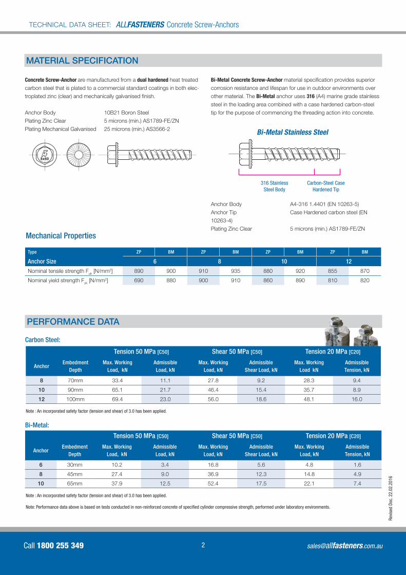
MATERIAL SPECIFICATION
Bi-Metal Concrete Screw-Anchor material specification provides superior
corrosion resistance and lifespan for use in outdoor environments over
other material. The Bi-Metal anchor uses 316 (A4) marine grade stainless
steel in the loading area combined with a case hardened carbon-steel
tip for the purpose of commencing the threading action into concrete.
Concrete Screw-Anchor are manufactured from a dual hardened heat treated
carbon steel that is plated to a commercial standard coatings in both elec-
troplated zinc (clear) and mechanically galvanised finish.
Anchor Body 10B21 Boron Steel
Plating Zinc Clear 5 microns (min.) AS1789-FE/ZN
Plating Mechanical Galvanised 25 microns (min.) AS3566-2
8x60
Bi-Metal Stainless Steel
Carbon-Steel Case Hardened Tip
316 Stainless Steel Body
PERFORMANCE DATA
Tension 50 MPa [C50] Shear 50 MPa [C50] Tension 20 MPa [C20]
AnchorEmbedment
Depth Max. Working
Load, kNAdmissible Load, kN
Max. Working Load, kN
Admissible Shear Load, kN
Max. Working Load, kN
Admissible Tension, kN
6 30mm 10.2 3.4 16.8 5.6 4.8 1.6
8 45mm 27.4 9.0 36.9 12.3 14.8 4.9
10 65mm 37.9 12.5 52.4 17.5 22.1 7.4
Bi-Metal:
Carbon Steel:
Note : An incorporated safety factor (tension and shear) of 3.0 has been applied.
Note: Performance data above is based on tests conducted in non-reinforced concrete of specified cylinder compressive strength, performed under laboratory environments.
8x60
Tension 50 MPa [C50] Shear 50 MPa [C50] Tension 20 MPa [C20]
AnchorEmbedment
Depth Max. Working
Load, kNAdmissible Load, kN
Max. Working Load, kN
Admissible Shear Load, kN
Max. Working Load kN
Admissible Tension, kN
8 70mm 33.4 11.1 27.8 9.2 28.3 9.4
10 90mm 65.1 21.7 46.4 15.4 35.7 8.9
12 100mm 69.4 23.0 56.0 18.6 48.1 16.0
Note : An incorporated safety factor (tension and shear) of 3.0 has been applied.
Anchor Body A4-316 1.4401 (EN 10263-5)
Anchor Tip Case Hardened carbon steel (EN
10263-4)
Plating Zinc Clear 5 microns (min.) AS1789-FE/ZN
Type ZP BM ZP BM ZP BM ZP BM
Anchor Size 6 8 10 12
Nominal tensile strength Fuk [N/mm2] 890 900 910 935 880 920 855 870
Nominal yield strength Fyk [N/mm2] 690 880 900 910 860 890 810 820
Mechanical Properties
3 WWW.ALLFASTENERS.COM.AUCall 1800 255 349
Revi
sed
Doc.
22.
02.2
016
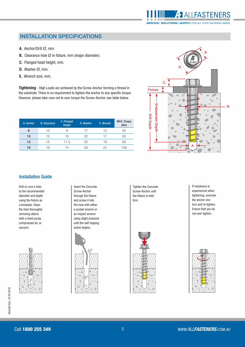
A. Anchor/Drill Ø, mm.
B. Clearance hole Ø in fixture, mm (major diameter).
C. Flanged head height, mm.
D. Washer Ø, mm.
E. Wrench size, mm.
8x60
A.
E.
D.
C.
B.
Em
bed
ment D
epth
Fixture
Drill D
epth
INSTALLATION SPECIFICATIONS
Installation Guide
Drill or core a hole to the recommended diameter and depth using the fixture as a template. Clean the hole thoroughly removing debris with a hand pump, compressed air, or vacuum.
Insert the Concrete Screw-Anchor through the fixture and screw it into the hole with either a socket wrench or an impact wrench using slight pressure until the self-tapping action begins.
Tighten the Concrete Screw-Anchor until the fixture is held firm.
If resistance is experienced when tightening, unscrew the anchor one turn and re-tighten. Ensure that you do not over tighten.
A. Anchor B. Clearance C. Flanged
HeightD. Washer E. Wrench
MAX. Torque (Nm)
8 10 8 17 13 45
10 13 10 22 17 55
12 15 11.5 25 19 80
16 19 14 29 24 100
Tightening - High Loads are achieved by the Screw-Anchor forming a thread in the substrate. There is no requirement to tighten the anchor to any specific torque. However, please take care not to over torque the Screw-Anchor, see table below.
4
Concrete Screw-AnchorsALLFASTENERS
TECHNICAL DATA SHEET:
Call 1800 255 349
Revi
sed
Doc.
22.
02.2
016
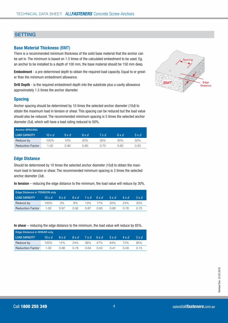
Base Material Thickness (BMT)There is a recommended minimum thickness of the solid base material that the anchor can be set in. The minimum is based on 1.5 times of the calculated embedment to be used. Eg. an anchor to be installed to a depth of 100 mm, the base material should be 150 mm deep.
Embedment - a pre-determined depth to obtain the required load capacity. Equal to or great-er than the minimum embedment allowance.
Drill Depth - is the required embedment depth into the substrate plus a cavity allowance approximately 1.5 times the anchor diameter.
Spacing Anchor spacing should be determined by 10 times the selected anchor diameter (10d) to obtain the maximum load in tension or shear. This spacing can be reduced but the load value should also be reduced. The recommended minimum spacing is 5 times the selected anchor diameter (5d), which will have a load rating reduced to 50%.
Edge Distance Should be determined by 10 times the selected anchor diameter (10d) to obtain the maxi-mum load in tension or shear. The recommended minimum spacing is 3 times the selected anchor diameter (3d).
In tension – reducing the edge distance to the minimum, the load value will reduce by 30%.
In shear – reducing the edge distance to the minimum, the load value will reduce by 85%.
SETTING
Edge Distance in TENSION only
LOAD CAPACITY 10 x d 9 x d 8 x d 7 x d 6 x d 5 x d 4 x d 3 x d
Reduce by 100% 3% 8% 13% 17% 20% 24% 30%
Reduction Factor 1.00 0.97 0.92 0.87 0.83 0.80 0.76 0.70
Anchor SPACING
LOAD CAPACITY 10 x d 9 x d 8 x d 7 x d 6 x d 5 x d
Reduce by 100% 10% 20% 30% 40% 50%
Reduction Factor 1.00 0.90 0.80 0.70 0.60 0.50
Edge Distance in SHEAR only
LOAD CAPACITY 10 x d 9 x d 8 x d 7 x d 6 x d 5 x d 4 x d 3 x d
Reduce by 100% 12% 24% 36% 47% 64% 72% 85%
Reduction Factor 1.00 0.88 0.76 0.64 0.53 0.41 0.28 0.15
BMT
Spacing
Edge Distance
5 WWW.ALLFASTENERS.COM.AUCall 1800 255 349
Revi
sed
Doc.
22.
02.2
016
8x60
8x60
8x60
A4Bi-Metal:
316 Stainless Steel + Case Hardened Tip
PRODUCT ORDERING INFORMATION
Bi-Metal Concrete Screw-Anchor: Hex Flange Head
CODEAnchor* x
Length (mm)Min.
Embedment (mm)Max. Fixture
Thickness (mm)Clearance Hole
Ø (mm)Wrench Size
(mm)
1SAHS06060 6 x 60 30 30 8.5 10 100 4001SAHS08075 8 x 75
4530
10 1350 300
1SAHS08095 8 x 95 50 50 3001SAHS10075 10 x 75
5025
13 1750 200
1SAHS10100 10 x 100 50 50 2001SAHS10120 10 x 120 70 50 200
*Drill diameter
Concrete Screw-Anchor: Hex Flange Head
8x60
8x60
8x60
A4
8x60
8x60
8x60
A4
Zinc Plated (Clear)
ZINC GALVANISEDAnchor* x
Length (mm)Min.
Embedment (mm)Max. Fixture
Thickness (mm)Clearance Hole
Ø (mm)Wrench Size
(mm)
1SAHZ08060 1SAHG08060 8 x 6035
2510 13
50 3001SAHZ08075 1SAHG08075 8 x 75 40 50 3001SAHZ08100 1SAHG08100 8 x 100 65 50 3001SAHZ10060 1SAHG10060 10 x 60
40
20
13 17
50 3001SAHZ10075 1SAHG10075 10 x 75 35 50 2001SAHZ10100 1SAHG10100 10 x 100 60 50 2001SAHZ10120 1SAHG10120 10 x 120 80 50 2001SAHZ12075 1SAHG12075 12 x 75
5025
15 1950 200
1SAHZ12100 1SAHG12100 12 x 100 50 50 2001SAHZ12150 1SAHG12150 12 x 150 100 25 1001SAHZ16100 1SAHG16100 16 x 100
6535
19 2415 60
1SAHZ16150 1SAHG16150 16 x 150 85 15 60
*Drill diameter
Mech. Galvanised
6
Concrete Screw-AnchorsALLFASTENERS
TECHNICAL DATA SHEET:
Call 1800 255 349
Revi
sed
Doc.
22.
02.2
016
Melbourne – Head Office 78 - 84 Logistics Street, Keilor Park VIC 3042
Tel 03 9330 0555 | Fax 03 9338 6434
Sydney65 Atkins Road, Ermington NSW 2115
Tel 02 8844 4550 | Fax 02 9807 7500
Adelaide116 Churchill Road North, Dry Creek SA 5094
Tel 08 8396 2781 | Fax 08 8263 3769
ALLFASTENERS holds a Management System Conformity Certificate with ISO 9001:2008 accreditation, for implementing quality management systems, standards and guidelines for the supply & express delivery of fasteners to the industrial, heavy industry, mining & construction industries. Certificate No. AU1439
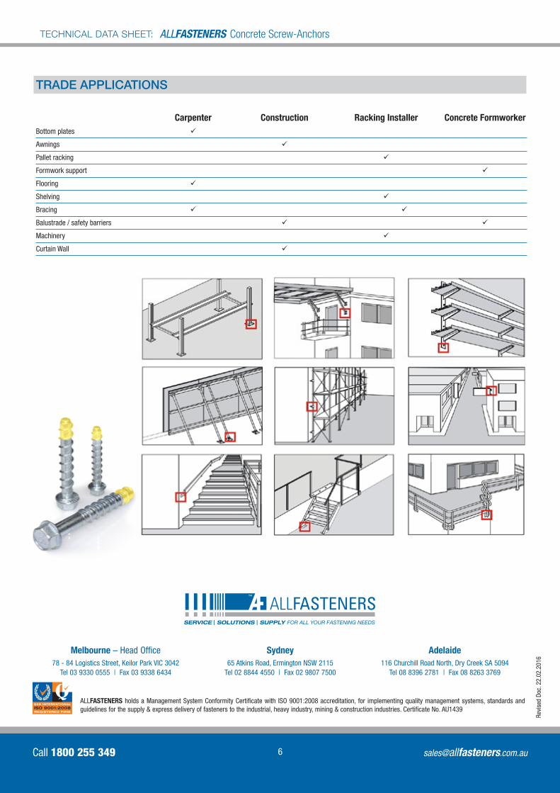
Carpenter Construction Racking Installer Concrete FormworkerBottom plates ü
Awnings ü
Pallet racking ü
Formwork support ü
Flooring ü
Shelving ü
Bracing ü ü
Balustrade / safety barriers ü§ § ü
Machinery ü
Curtain Wall ü
TRADE APPLICATIONS