Embed Size (px)
Citation preview
August 2015
Project: Customer: Engineer: Pump Manufacturer:
Model GPL + GLULimted Service Full Voltage
Across the Line StartElectric Fire Pump Controller
with Automatic Power Transfer Switch
Technical Data Submittal Document
Contents:• Data Sheets • Dimensional Data• Wiring Schematics• Field Connections
Note: The drawings included in this package are for controllers covered under our standard offering. Actual AS BUILT drawings may differ from what is shown in this package.
SEISMIC COMPLIANT
ICC-ES AC156 IBC 2015CBC 2013
Technical Data Model GPL + GLU Electric Fire Pump Controller with Automatic Power Transfer Switch
August 2015 2
Standard,Listings,
Approvals andCertifications
Built to NFPA 20 (latest edition)
Underwriters Laboratory (UL)• UL218 - Fire Pump Controllers• UL 1008 - Automatic power transfer switches for fire pump controllers• CSA C22.2 No. 14 Industrial Control Equipment
New York City Accepted for use in the City of New York by the Department of BuildingsSeismic certifications See page 6 for details
Enclosure
Protection Rating□ Standard: NEMA 2Optional□ NEMA 12□ NEMA 3□ NEMA 3R□ NEMA 4
Accessories• Wall mounting lugs• Keylock handle
*Please see Disconnecting Means details on page 3.
□ NEMA 4X-304 sst painted□ NEMA 4X-304 sst brushed finish□ NEMA 4X-316 sst painted□ NEMA 4X-316 sst brushed finish
Paint Specifications• Red RAL3002• Powder coating• Glossy textured finish
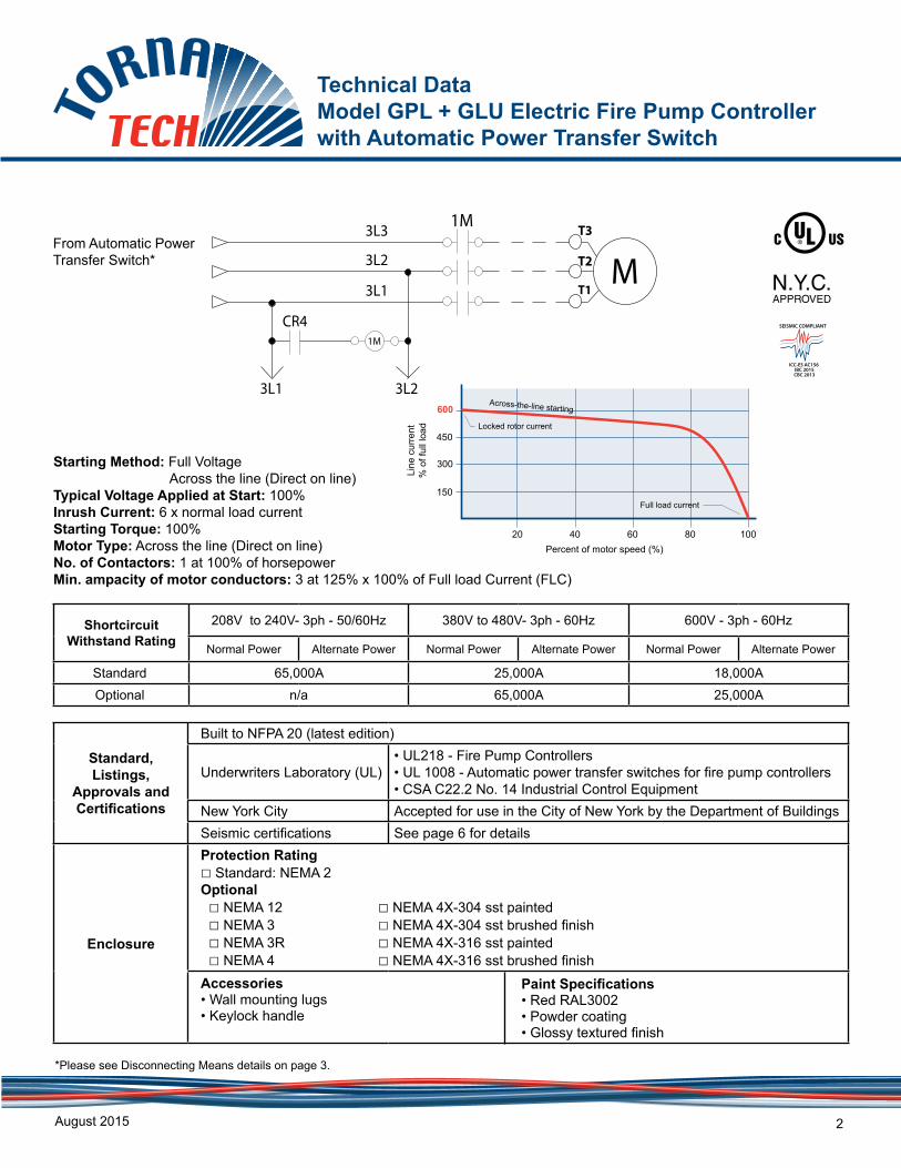
Starting Method: Full Voltage Across the line (Direct on line)Typical Voltage Applied at Start: 100%Inrush Current: 6 x normal load currentStarting Torque: 100%Motor Type: Across the line (Direct on line)No. of Contactors: 1 at 100% of horsepowerMin. ampacity of motor conductors: 3 at 125% x 100% of Full load Current (FLC)
600Across-the-line starting
Locked rotor current
Full load current
Percent of motor speed (%)
Line
cur
rent
% o
f ful
l loa
d
20 40 60 80 100
450
300
150
GPA
From Automatic Power Transfer Switch*
Shortcircuit Withstand Rating
208V to 240V- 3ph - 50/60Hz 380V to 480V- 3ph - 60Hz 600V - 3ph - 60Hz
Normal Power Alternate Power Normal Power Alternate Power Normal Power Alternate Power
Standard 65,000A 25,000A 18,000AOptional n/a 65,000A 25,000A
MT2
T1
T31M
1M
CR4
3L1 3L2
3L1
3L2
3L3
SEISMIC COMPLIANT
ICC-ES AC156 IBC 2015CBC 2013
Technical Data Model GPL+ GLU Electric Fire Pump Controller with Automatic Power Transfer Switch
August 2015 3
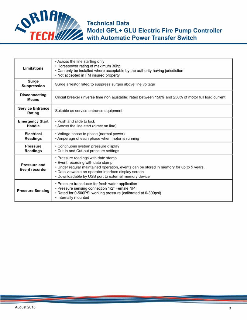
Limitations
• Across the line starting only • Horsepower rating of maximum 30hp• Can only be installed where acceptable by the authority having jurisdiction • Not accepted in FM insured property
Surge Suppression Surge arrestor rated to suppress surges above line voltage
Disconnecting Means Circuit breaker (inverse time non ajustable) rated between 150% and 250% of motor full load current
Service Entrance Rating Suitable as service entrance equipment
Emergency Start Handle
• Push and slide to lock • Across the line start (direct on line)
Electrical Readings
• Voltage phase to phase (normal power)• Amperage of each phase when motor is running
Pressure Readings
• Continuous system pressure display• Cut-in and Cut-out pressure settings
Pressure and Event recorder
• Pressure readings with date stamp• Event recording with date stamp• Under regular maintained operation, events can be stored in memory for up to 5 years.• Data viewable on operator interface display screen• Downloadable by USB port to external memory device
Pressure Sensing
• Pressure transducer for fresh water application• Pressure sensing connection 1/2” Female NPT• Rated for 0-500PSI working pressure (calibrated at 0-300psi)• Internally mounted
Technical Data Model GPL + GLU Electric Fire Pump Controller with Automatic Power Transfer Switch
August 2015 4
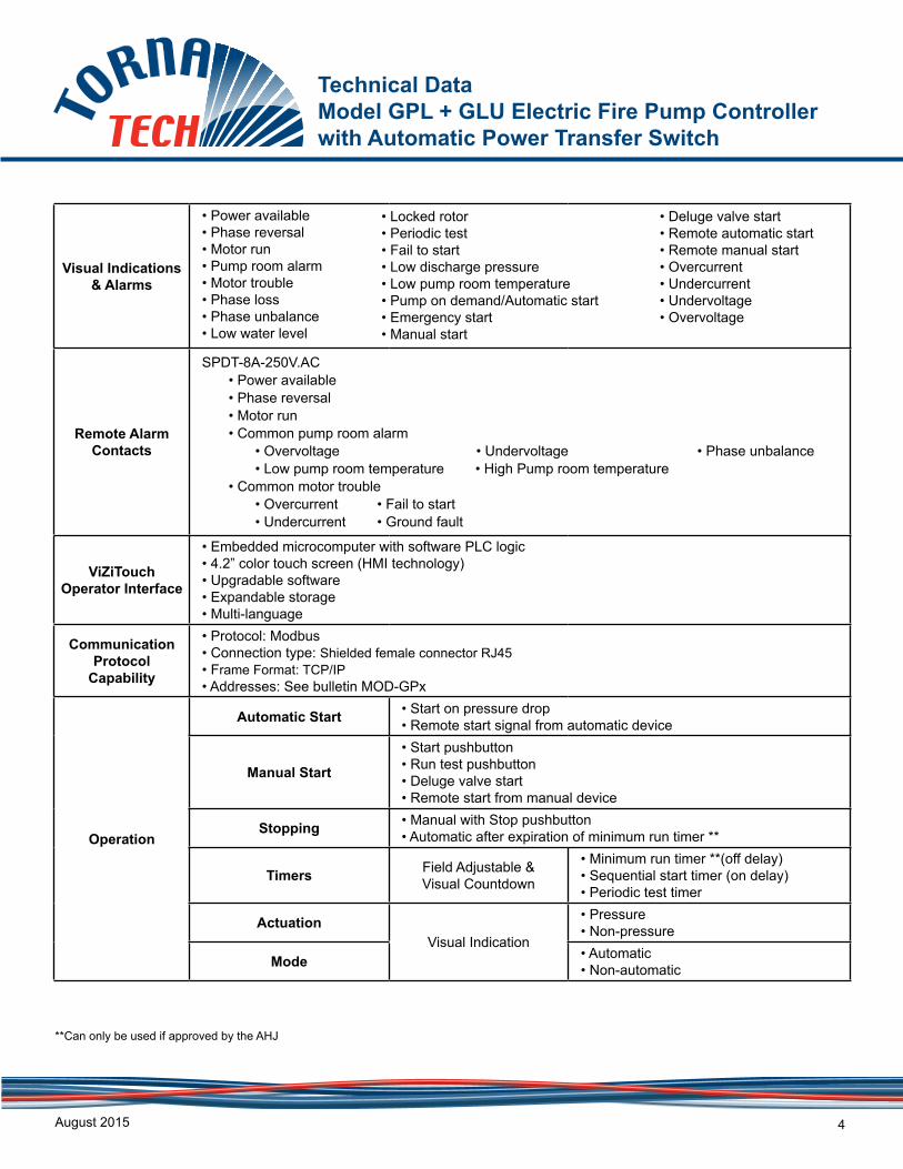
Visual Indications & Alarms
• Power available• Phase reversal• Motor run• Pump room alarm• Motor trouble• Phase loss• Phase unbalance• Low water level
Remote Alarm Contacts
SPDT-8A-250V.AC• Power available• Phase reversal• Motor run• Common pump room alarm
• Overvoltage • Undervoltage • Phase unbalance• Low pump room temperature • High Pump room temperature
• Common motor trouble • Overcurrent • Fail to start• Undercurrent • Ground fault
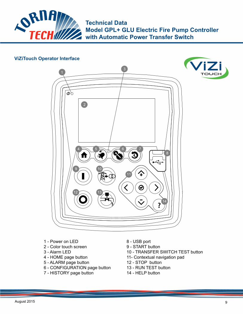
ViZiTouch Operator Interface
• Embedded microcomputer with software PLC logic• 4.2” color touch screen (HMI technology)• Upgradable software• Expandable storage• Multi-language
Communication Protocol
Capability
• Protocol: Modbus• Connection type: Shielded female connector RJ45• Frame Format: TCP/IP• Addresses: See bulletin MOD-GPx
Operation
Automatic Start • Start on pressure drop• Remote start signal from automatic device
Manual Start
• Start pushbutton• Run test pushbutton• Deluge valve start• Remote start from manual device
Stopping • Manual with Stop pushbutton• Automatic after expiration of minimum run timer **
Timers Field Adjustable & Visual Countdown
• Minimum run timer **(off delay)• Sequential start timer (on delay)• Periodic test timer
ActuationVisual Indication
• Pressure• Non-pressure
Mode • Automatic• Non-automatic
• Deluge valve start• Remote automatic start• Remote manual start• Overcurrent • Undercurrent• Undervoltage• Overvoltage
• Locked rotor• Periodic test• Fail to start• Low discharge pressure• Low pump room temperature • Pump on demand/Automatic start• Emergency start• Manual start
**Can only be used if approved by the AHJ
Technical Data Model GPL+ GLU Electric Fire Pump Controller with Automatic Power Transfer Switch
August 2015 5
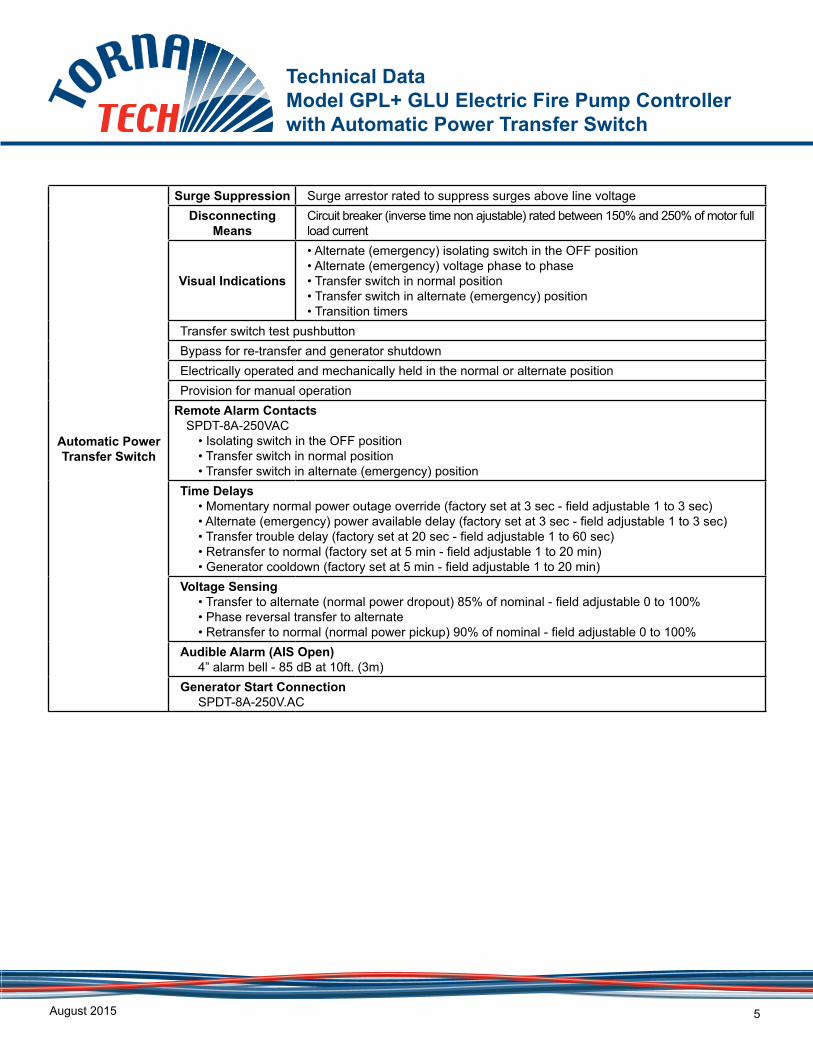
Automatic Power Transfer Switch
Surge Suppression Surge arrestor rated to suppress surges above line voltageDisconnecting
MeansCircuit breaker (inverse time non ajustable) rated between 150% and 250% of motor full load current
Visual Indications
• Alternate (emergency) isolating switch in the OFF position• Alternate (emergency) voltage phase to phase• Transfer switch in normal position• Transfer switch in alternate (emergency) position• Transition timers
Transfer switch test pushbuttonBypass for re-transfer and generator shutdownElectrically operated and mechanically held in the normal or alternate positionProvision for manual operation
Remote Alarm ContactsSPDT-8A-250VAC
• Isolating switch in the OFF position• Transfer switch in normal position• Transfer switch in alternate (emergency) position
Time Delays• Momentary normal power outage override (factory set at 3 sec - field adjustable 1 to 3 sec)• Alternate (emergency) power available delay (factory set at 3 sec - field adjustable 1 to 3 sec)• Transfer trouble delay (factory set at 20 sec - field adjustable 1 to 60 sec)• Retransfer to normal (factory set at 5 min - field adjustable 1 to 20 min)• Generator cooldown (factory set at 5 min - field adjustable 1 to 20 min)
Voltage Sensing• Transfer to alternate (normal power dropout) 85% of nominal - field adjustable 0 to 100%• Phase reversal transfer to alternate• Retransfer to normal (normal power pickup) 90% of nominal - field adjustable 0 to 100%
Audible Alarm (AIS Open)4” alarm bell - 85 dB at 10ft. (3m)
Generator Start ConnectionSPDT-8A-250V.AC
Technical Data Model GPL + GLU Electric Fire Pump Controller with Automatic Power Transfer Switch
August 2015 6
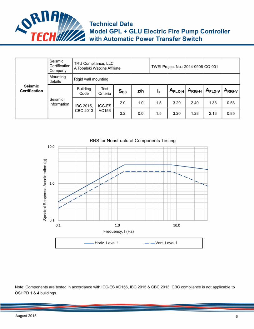
Seismic Certification
Seismic Certification Company
TRU Compliance, LLCA Tobalski Watkins Affiliate TWEI Project No.: 2014-0906-CO-001
Mounting details Rigid wall mounting
Seismic Information
Building Code
Test Criteria SDS z/h IP AFLX-H ARIG-H AFLX-V ARIG-V
IBC 2015, CBC 2013
ICC-ES AC156
2.0 1.0 1.5 3.20 2.40 1.33 0.53
3.2 0.0 1.5 3.20 1.28 2.13 0.85
0.1
1.0
10.0
0.1 1.0 10.0
Spe
ctra
l Res
pons
e A
ccel
erat
ion
(g)
Frequency, f (Hz)
RRS for Nonstructural Components Testing
Horiz. Level 1 Vert. Level 1
Note: Components are tested in accordance with ICC-ES AC156, IBC 2015 & CBC 2013. CBC compliance is not applicable to OSHPD 1 & 4 buildings.
Technical Data Model GPL+ GLU Electric Fire Pump Controller with Automatic Power Transfer Switch
August 2015 7
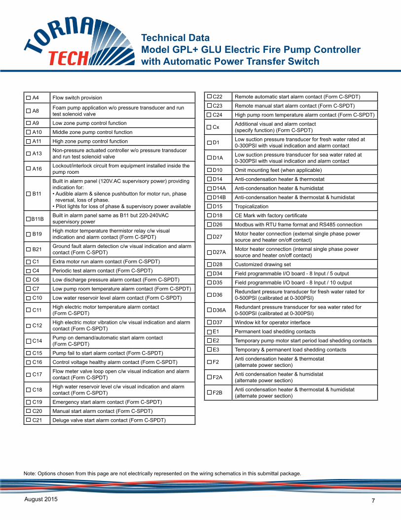
A4 Flow switch provision
A8 Foam pump application w/o pressure transducer and run test solenoid valve
A9 Low zone pump control function
A10 Middle zone pump control function
A11 High zone pump control function
A13 Non-pressure actuated controller w/o pressure transducer and run test solenoid valve
A16 Lockout/interlock circuit from equipment installed inside the pump room
B11
Built in alarm panel (120V.AC supervisory power) providing indication for:• Audible alarm & silence pushbutton for motor run, phase reversal, loss of phase.• Pilot lights for loss of phase & supervisory power available
B11BBuilt in alarm panel same as B11 but 220-240VAC supervisory power
B19 High motor temperature thermistor relay c/w visual indication and alarm contact (Form C-SPDT)
B21 Ground fault alarm detection c/w visual indication and alarm contact (Form C-SPDT)
C1 Extra motor run alarm contact (Form C-SPDT)
C4 Periodic test alarm contact (Form C-SPDT)
C6 Low discharge pressure alarm contact (Form C-SPDT)
C7 Low pump room temperature alarm contact (Form C-SPDT)
C10 Low water reservoir level alarm contact (Form C-SPDT)
C11 High electric motor temperature alarm contact (Form C-SPDT)
C12 High electric motor vibration c/w visual indication and alarm contact (Form C-SPDT)
C14 Pump on demand/automatic start alarm contact(Form C-SPDT)
C15 Pump fail to start alarm contact (Form C-SPDT)
C16 Control voltage healthy alarm contact (Form C-SPDT)
C17 Flow meter valve loop open c/w visual indication and alarm contact (Form C-SPDT)
C18 High water reservoir level c/w visual indication and alarm contact (Form C-SPDT)
C19 Emergency start alarm contact (Form C-SPDT)
C20 Manual start alarm contact (Form C-SPDT)
C21 Deluge valve start alarm contact (Form C-SPDT)
C22 Remote automatic start alarm contact (Form C-SPDT)
C23 Remote manual start alarm contact (Form C-SPDT)
C24 High pump room temperature alarm contact (Form C-SPDT)
Cx Additional visual and alarm contact (specify function) (Form C-SPDT)
D1 Low suction pressure transducer for fresh water rated at 0-300PSI with visual indication and alarm contact
D1A Low suction pressure transducer for sea water rated at 0-300PSI with visual indication and alarm contact
D10 Omit mounting feet (when applicable)
D14 Anti-condensation heater & thermostat
D14A Anti-condensation heater & humidistat
D14B Anti-condensation heater & thermostat & humidistat
D15 Tropicalization
D18 CE Mark with factory certificate
D26 Modbus with RTU frame format and RS485 connection
D27 Motor heater connection (external single phase power source and heater on/off contact)
D27A Motor heater connection (internal single phase power source and heater on/off contact)
D28 Customized drawing set
D34 Field programmable I/O board - 8 Input / 5 output
D35 Field programmable I/O board - 8 Input / 10 output
D36 Redundant pressure transducer for fresh water rated for 0-500PSI (calibrated at 0-300PSI)
D36A Redundant pressure transducer for sea water rated for 0-500PSI (calibrated at 0-300PSI)
D37 Window kit for operator interface
E1 Permanent load shedding contacts
E2 Temporary pump motor start period load shedding contacts
E3 Temporary & permanent load shedding contacts
F2 Anti condensation heater & thermostat (alternate power section)
F2A Anti condensation heater & humidistat (alternate power section)
F2B Anti condensation heater & thermostat & humidistat (alternate power section)
Note: Options chosen from this page are not electrically represented on the wiring schematics in this submittal package.
Technical Data Model GPL + GLU Electric Fire Pump Controller with Automatic Power Transfer Switch
August 2015 8
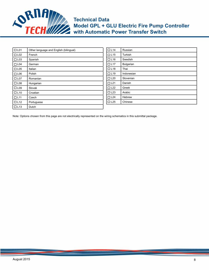
L01 Other language and English (bilingual)
L02 French
L03 Spanish
L04 German
L05 Italian
L06 Polish
L07 Romanian
L08 Hungarian
L09 Slovak
L10 Croatian
L11 Czech
L12 Portuguese
L13 Dutch
L14 Russian
L15 Turkish
L16 Swedish
L17 Bulgarian
L18 Thai
L19 Indonesian
L20 Slovenian
L21 Danish
L22 Greek
L23 Arabic
L24 Hebrew
L25 Chinese
Note: Options chosen from this page are not electrically represented on the wiring schematics in this submittal package.
Technical Data Model GPL+ GLU Electric Fire Pump Controller with Automatic Power Transfer Switch
August 2015 9
??
4
9 10
12 13
11
14
5 6 7
3
2
1
8
PMS 295 PMS 361 Noir
ViZiTouch Operator Interface
1 - Power on LED2 - Color touch screen3 - Alarm LED4 - HOME page button 5 - ALARM page button6 - CONFIGURATION page button7 - HISTORY page button
8 - USB port9 - START button10 - TRANSFER SWITCH TEST button11- Contextual navigation pad12 - STOP button13 - RUN TEST button14 - HELP button
251818 253575-600 / 60 30
FIRST ISSUE12/01/100.
GLUALT. SIDE
WITHSTAND RATING [kA] RMS
65N/A15 653200-208 / 60
3200-208 / 60
380-416 / 50-60440-480 / 50-60
230-240 / 50-6033
3
230-240 / 50-60 3
6565 N/A30
253030 25
30 652565
65 25
N/A 65
6515 65N/A
HP RATING
1 PHASEMIN
VOLT/Hz
MAXStd HIGH Std
NORMAL SIDE
N/A
N/A
6565
N/A
N/A
HIGH
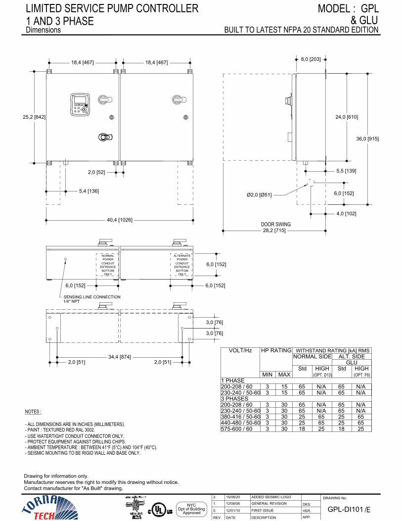
1 AND 3 PHASELIMITED SERVICE PUMP CONTROLLER
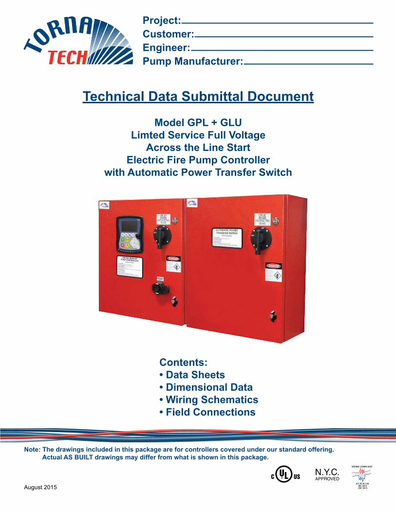
Dimensions& GLU
BUILT TO LATEST NFPA 20 STANDARD EDITION
ENTRANCECONDUIT
ONLYBOTTOM
5,4 [136]
5,5 [139]
18,4 [467] 18,4 [467]
2,0 [52]
25,2 [642] 24,0 [610]
40,4 [1026]
8,0 [203]
4,0 [102]
6,0 [152]Ø2,0 [Ø51]
28,2 [715]DOOR SWING
36,0 [915]
3,0 [76]
3,0 [76]
2,0 [51]34,4 [874]
2,0 [51]
6,0 [152]
6,0 [152]
NORMALPOWER POWER
CONDUITENTRANCE
BOTTOMONLY
ALTERNATE
6,0 [152]
(OPT. D13) (OPT. F6)
3 PHASES
GPLMODEL :
VER.
DESCRIPTIONDATEREV. APP.
DES.
DRAWING No.
NOTES :
- PAINT : TEXTURED RED RAL 3002.- ALL DIMENSIONS ARE IN INCHES (MILLIMETERS).
- AMBIENT TEMPERATURE : BETWEEN 41°F (5°C) AND 104°F (40°C).- PROTECT EQUIPMENT AGAINST DRILLING CHIPS.- USE WATERTIGHT CONDUIT CONNECTOR ONLY.
Drawing for information only.Manufacturer reserves the right to modify this drawing without notice.Contact manufacturer for "As Built" drawing.
GPL-DI101 /E
SENSING LINE CONNECTION1/4'' NPT
NYCDpt of Building
Approved
GENERAL REVISION12/08/061.
ADDED SEISMIC LOGO15/08/202.
- SEISMIC MOUNTING TO BE RIGID WALL AND BASE ONLY.
Power
Available
Phase
Reversal
Common
Pump Room
Motor
Trouble
Alarm
Motor
Running
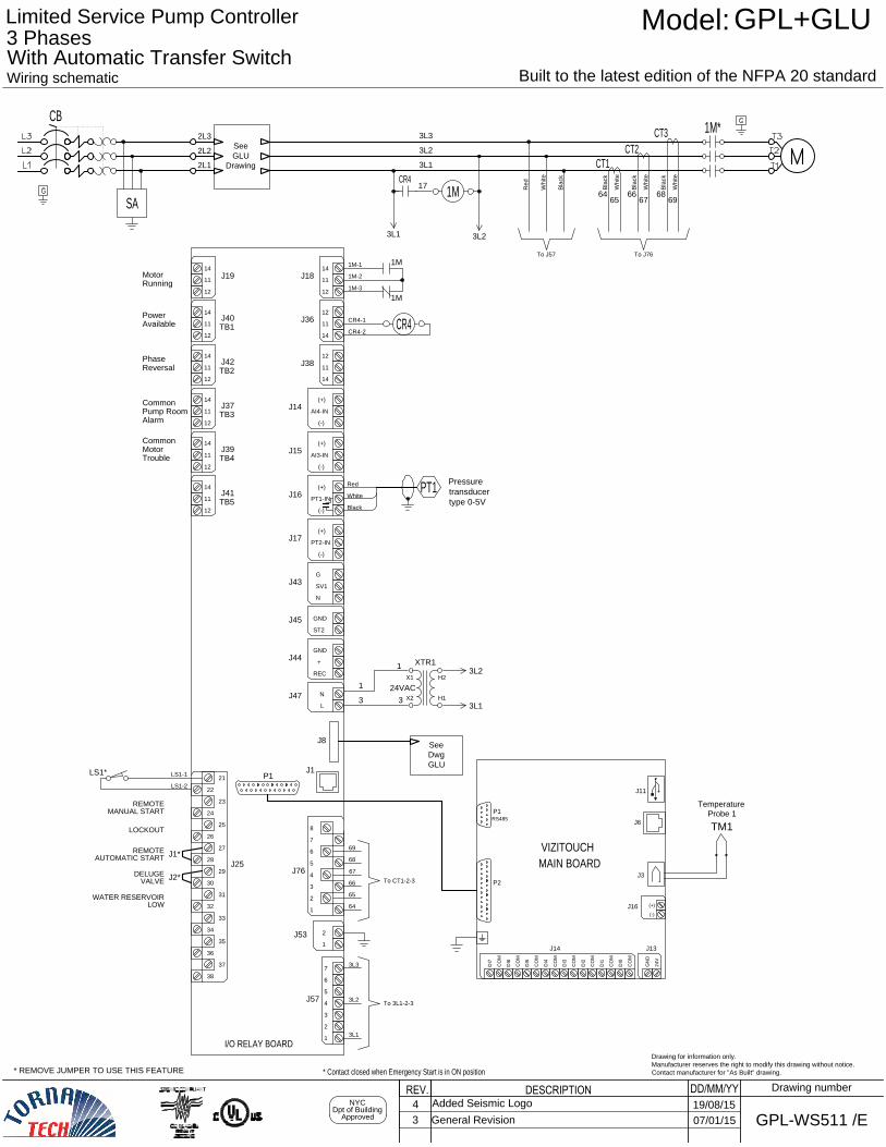
* Contact closed when Emergency Start is in ON position
J40
J42
J37
J39
Common
11
12
14
J19 J18
J41
11
14
12
J36
11
14
12
J38
AI4-IN
(-)
(+)
J14
J15
J16
J17
PT1
Black
Red
White
SV1
N
G
J43
GND
ST2
J45
+
REC
GND
J44
N
L
J47
24VAC
3
1
3L1
3L2
XTR1
X1
X2
H2
H1
3
1
J8
6
5
7
J57
3
2
4
1
6
5
7
J76
3
2
4
1
8
31
32
30
J25
34
35
33
36
29
23
27
25
21
24
22
26
28
2
1
J53
J1
I/O RELAY BOARD
P1
37
38
AI3-IN
(-)
(+)
PT1-IN
(-)
(+)
PT2-IN
(-)
(+)
TB1
TB2
TB3
TB4
TB5
Pressure
transducer
type 0-5V
P2
DI0
CO
M
CO
M
J14
DI1
CO
M
DI2
CO
M
DI3
CO
M
DI4
CO
M
DI5
CO
M
DI6
CO
M
DI7
24V
GN
D
J13
(+)
(-)
J16
J6
RS485
P1
J3
J11
MAIN BOARD
LOCKOUT
REMOTE
MANUAL START
DELUGE
VALVE
WATER RESERVOIR
LOW
REMOTE
AUTOMATIC START
TM1
See
Dwg
GLU
VIZITOUCH
J2*
J1*
* REMOVE JUMPER TO USE THIS FEATURE
11
12
14
11
12
14
11
12
14
11
12
14
11
12
14
11
12
14
Wiring schematic
Built to the latest edition of the NFPA 20 standard
DD/MM/YYDESCRIPTIONREV.NYC
Dpt of Building
Approved
Drawing number
Limited Service Pump Controller
Model:GPL+GLU
WS511 /EGPL-
Drawing for information only.
Manufacturer reserves the right to modify this drawing without notice.
Contact manufacturer for "As Built" drawing.
3 Phases
With Automatic Transfer Switch
2L2
2L1
2L3
See
GLU
Drawing
3L1
3L3
3L2
1M*
1M
CR4
17
SA
3L2
3L1
CT1
CT3
CT2
CB
4
Added Seismic Logo
19/08/15
3 General Revision07/01/15
Bla
ck
Wh
ite
Wh
ite
Re
d
Bla
ck
Bla
ck
Wh
ite
Wh
ite
Bla
ck
64
65
66
67
68
69
68
67
65
64
66
69
To J76
LS1*
Probe 1
Temperature
1M
1M
1M-2
1M-3
1M-1
CR4
CR4-1
CR4-2
LS1-2
LS1-1
To J57
To CT1-2-3
To 3L1-2-3
3L3
3L2
3L1
24Vdc
24Vrect
COM
J38
J8
6
5
7
J57
3
2
4
1
I/O BOARD Tr. Sw.
DESCRIPTIONDATEREV.
2L
2
2L
1
2E
2
2E
3
2E
1
2L1
2L3
2L2
M
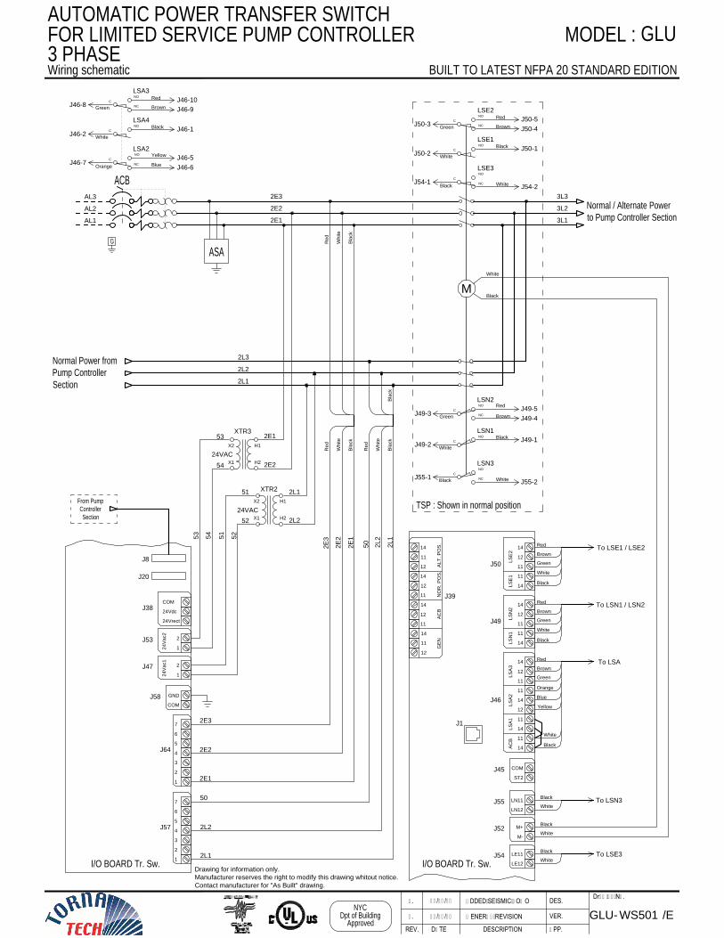
GLU-
Drawing No.
APP.
VER.
DES.
BUILT TO LATEST NFPA 20 STANDARD EDITION
FOR LIMITED SERVICE PUMP CONTROLLER
2E2
2E1
2E3
Wiring schematic
3L2
3L1
3L3
MODEL :
LSN1
NO
C
C
NC
NO
LSN2
C
NO
LSE1
C
NC
NO
LSE3
50
Normal Power from
Pump Controller
Section
Normal / Alternate Power
to Pump Controller Section
TSP : Shown in normal position
/EWS501
GLU
Re
d
Wh
ite
Bla
ck
Re
d
Wh
ite
Bla
ck
Bla
ck
Bla
ck
AL1
AL2
AL3
ACB
J49-4
Red
Green
Black
White
J49-1
J49-2
J49-5
J49-3
Brown
J50-1
White
White
Black
J54-2
J54-1
J50-2
Black
X2 H1
XTR3
X2
X1
X1
H1
H2
H2
XTR2
24VAC
24VAC
51
52
54
53
53
51
54
52
2L1
2E2
2E1
2L2
GENERAL REVISION1. 12/08/06
J20
6
5
7
J64
3
2
4
1
J53
2
1
J47
2
1
J50
J1
J49
14
J46
12
11
11
14
12
11
14
11
14
J45
COM
ST2
J55
LN11
LN12
J52
M+
M-
J54
LE11
LE12
11
12
14
J39
14
12
11
14
11
12
AL
T. P
OS
.N
OR
. P
OS
.A
CB
GE
N
12
11
14
C
NC
NO
LSE2
J50-4
Red
Green
J50-5
J50-3
Brown
LSN3
NO
C
NC
White
Black
J55-2
J55-1
24
Va
c2
24
Va
c1
J58
GND
COM
I/O BOARD Tr. Sw.
Green
Brown
Black
White
Red
Green
Brown
Black
White
Red
To LSE1 / LSE2
To LSN3
To LSE3
White
White
Black
Black
To LSN1 / LSN2
From Pump
Controller
Section
2L2
2L1
50
2E2
2E3
2E1
White
Black
White
Black
AC
BL
SA
1L
SA
2L
SA
3
11
14
14
12
11
LS
N1
LS
E1
LS
E2
LS
N2
11
14
14
12
11
Re
d
Wh
ite
Drawing for information only.
Manufacturer reserves the right to modify this drawing whitout notice.
Contact manufacturer for "As Built" drawing.
3 PHASE
ASA
NYC
Dpt of Building
Approved
AUTOMATIC POWER TRANSFER SWITCH
ADDED SEISMIC LOGO2. 15/08/20
C
NO
LSA4
C
NC
NO
LSA2
J46-1
White
Blue
Orange
J46-6
J46-7
J46-2
Black
C
NC
NO
LSA3
J46-9
Red
Green
J46-10
J46-8
Brown
Yellow
J46-5
Green
Brown
Red
To LSA
Black
White
Orange
Blue
Yellow
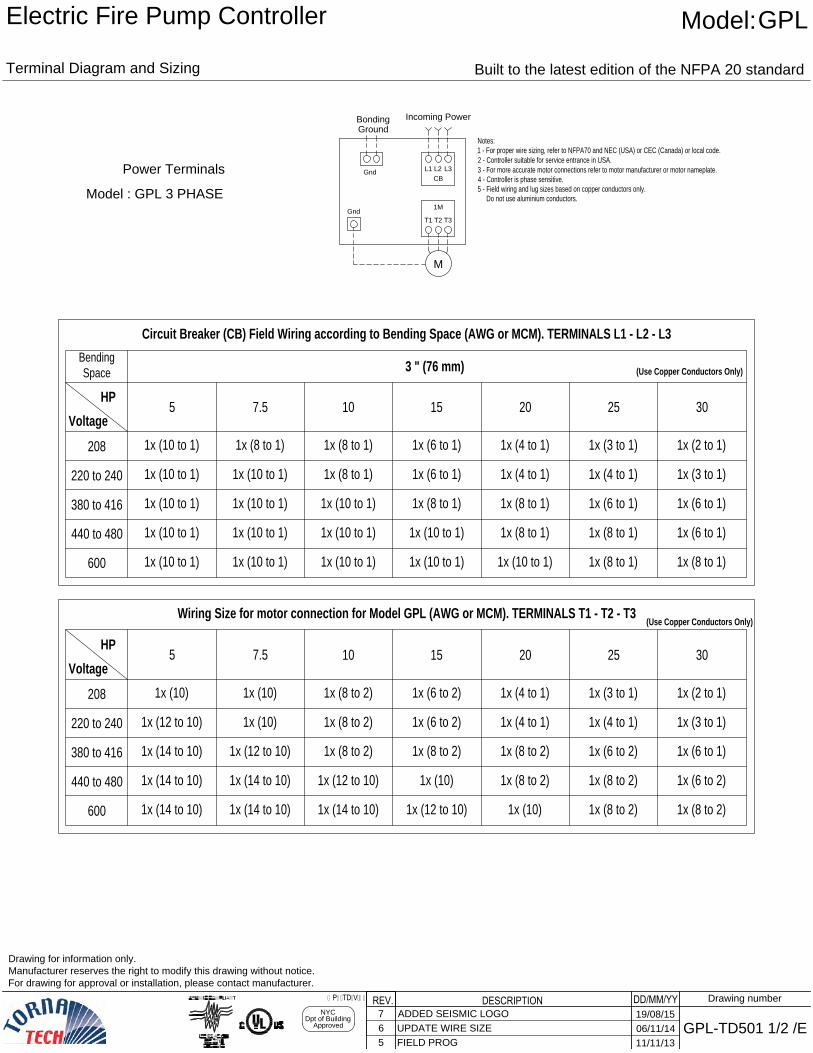
Model : GPL 3 PHASE
M
Gnd
T1 T3
1M
Incoming Power
Bonding
Gnd
L1
CB
Ground
L3
Power Terminals
5 7.5 10 15 20 25
220 to 240
380 to 416
600
440 to 480
208
1x (10)
30
1x (14 to 10)
1x (14 to 10)
1x (14 to 10)
1x (12 to 10)
1x (14 to 10)
1x (14 to 10)
1x (12 to 10)
1x (10)
1x (10)
1x (14 to 10)
1x (12 to 10)
1x (8 to 2)
1x (8 to 2)
1x (8 to 2)
1x (12 to 10)
1x (10)
1x (8 to 2)
1x (6 to 2)
1x (6 to 2)
1x (10)
1x (8 to 2)
1x (8 to 2)
1x (4 to 1)
1x (4 to 1)
1x (8 to 2)
1x (8 to 2)
1x (6 to 2)
1x (4 to 1)
1x (3 to 1)
1x (8 to 2)
1x (6 to 2)
1x (6 to 1)
1x (3 to 1)
1x (2 to 1)
5 7.5 10 15 20 25
220 to 240
380 to 416
600
440 to 480
208
1x (10 to 1)
30
1x (8 to 1)
3 " (76 mm)
1x (10 to 1)
1x (10 to 1)
1x (10 to 1)
1x (10 to 1)
1x (10 to 1)
1x (10 to 1)
1x (10 to 1)
1x (10 to 1)
1x (10 to 1)
1x (10 to 1)
1x (10 to 1)
1x (8 to 1)
1x (8 to 1)
1x (10 to 1)
1x (10 to 1)
1x (8 to 1)
1x (6 to 1)
1x (6 to 1)
1x (10 to 1)
1x (8 to 1)
1x (8 to 1)
1x (4 to 1)
1x (4 to 1)
1x (8 to 1)
1x (8 to 1)
1x (6 to 1)
1x (4 to 1)
1x (3 to 1)
1x (8 to 1)
1x (6 to 1)
1x (6 to 1)
1x (3 to 1)
1x (2 to 1)
Wiring Size for motor connection for Model GPL (AWG or MCM). TERMINALS T1 - T2 - T3
Voltage
Voltage
Circuit Breaker (CB) Field Wiring according to Bending Space (AWG or MCM). TERMINALS L1 - L2 - L3
Bending
Space
HP
HP
L2
T2
(Use Copper Conductors Only)
(Use Copper Conductors Only)
Drawing for information only.
Manufacturer reserves the right to modify this drawing without notice.
For drawing for approval or installation, please contact manufacturer.
DD/MM/YYDESCRIPTIONREV.NYC
Dpt of Building
Approved
6 UPDATE WIRE SIZE06/11/14
Drawing number
GPL-TD501 1/2 /E
Terminal Diagram and Sizing
Built to the latest edition of the NFPA 20 standard
Model:GPL
Electric Fire Pump Controller
5 FIELD PROG11/11/13
GPL-TD-ViZi
Notes:
1 - For proper wire sizing, refer to NFPA70 and NEC (USA) or CEC (Canada) or local code.
2 - Controller suitable for service entrance in USA.
3 - For more accurate motor connections refer to motor manufacturer or motor nameplate.
4 - Controller is phase sensitive.
5 - Field wiring and lug sizes based on copper conductors only.
Do not use aluminium conductors.
7 ADDED SEISMIC LOGO19/08/15
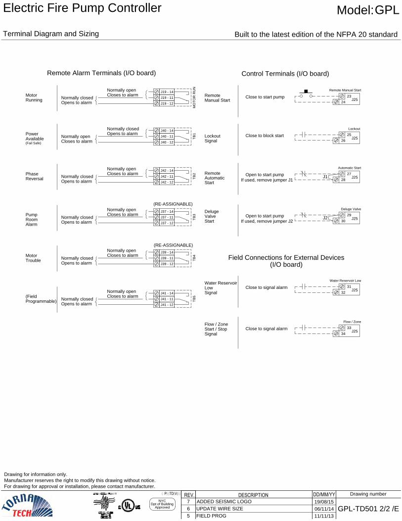
Control Terminals (I/O board)
Running
Motor
Trouble
Motor
Reversal
Phase
Available
Power
Remote Alarm Terminals (I/O board)
(Fail Safe)
Alarm
Room
Pump
Close to start pump
J19 - 14
J19 - 11
J19 - 12
Normally closed
Opens to alarm
Closes to alarm
Normally open
J40 - 14
J40 - 11
J40 - 12
Normally open
Closes to alarm
Opens to alarm
Normally closed
J42 - 14
J42 - 11
J42 - 12
Normally closed
Opens to alarm
Closes to alarm
Normally open
J37 - 14
J37 - 11
J37 - 12
Normally closed
Opens to alarm
Closes to alarm
Normally open
J39 - 14
J39 - 11
J39 - 12
Normally closed
Opens to alarm
Closes to alarm
Normally open
23
24
J25
Remote Manual Start
Open to start pump
27
28
J25
Automatic Start
Start
Deluge
Valve
Open to start pump
29
30
J25
Deluge Valve
Signal
Water Reservoir
Low
Close to signal alarm
31
32
J25
Water Reservoir Low
Signal
Flow / Zone
Start / Stop
33
34
J25
Flow / Zone
(I/O board)
Close to signal alarm
TB
1T
B2
TB
3T
B4
Signal
Lockout
Close to block start
25
26
J25
Lockout
J1
If used, remove jumper J1
MO
TO
R R
UN
J2
If used, remove jumper J2
Field Connections for External Devices
Remote
Manual Start
Automatic
Start
Remote
Programmable)
(Field
J41 - 14
J41 - 11
J41 - 12
Normally closed
Opens to alarm
Closes to alarm
Normally open
TB
5
(RE-ASSIGNABLE)
(RE-ASSIGNABLE)
Drawing for information only.
Manufacturer reserves the right to modify this drawing without notice.
For drawing for approval or installation, please contact manufacturer.
DD/MM/YYDESCRIPTIONREV.NYC
Dpt of Building
Approved
6 UPDATE WIRE SIZE06/11/14
Drawing number
GPL-TD501 2/2 /E
Terminal Diagram and Sizing
Built to the latest edition of the NFPA 20 standard
Model:GPL
Electric Fire Pump Controller
5 FIELD PROG11/11/13
GPL-TD-ViZi
7 ADDED SEISMIC LOGO19/08/15
AL1 AL2
ACB
12
11
14
J39
14
12
11
14
11
12
AL
T. P
OS
.N
OR
. P
OS
.A
CB
GE
N
12
11
14
J39
5 7.5 10 15 20 25
220 to 240
380 to 416
600
440 to 480
208
1x (10 to 1)
30
1x (8 to 1)
3 " (76 mm)
1x (10 to 1)
1x (10 to 1)
1x (10 to 1)
1x (10 to 1)
1x (10 to 1)
1x (10 to 1)
1x (10 to 1)
1x (10 to 1)
1x (10 to 1)
1x (10 to 1)
1x (10 to 1)
1x (8 to 1)
1x (8 to 1)
1x (10 to 1)
1x (10 to 1)
1x (8 to 1)
1x (6 to 1)
1x (6 to 1)
1x (10 to 1)
1x (8 to 1)
1x (8 to 1)
1x (4 to 1)
1x (4 to 1)
1x (8 to 1)
1x (8 to 1)
1x (6 to 1)
1x (4 to 1)
1x (3 to 1)
1x (8 to 1)
1x (6 to 1)
1x (6 to 1)
1x (3 to 1)
1x (2 to 1)
HP
AL2 AL3
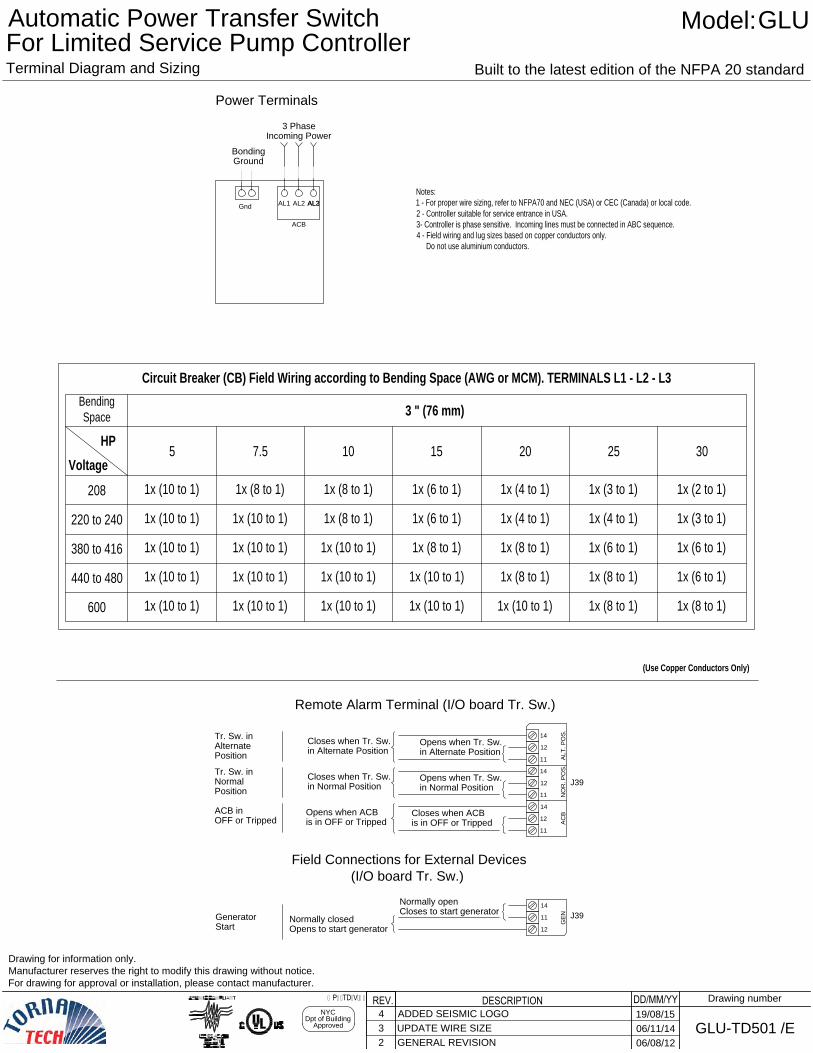
Bonding
Ground
3 Phase
Incoming Power
Power Terminals
Gnd
Remote Alarm Terminal (I/O board Tr. Sw.)
Closes to start generator
Normally open
Opens to start generator
Normally closed
Start
Generator
is in OFF or Tripped
Closes when ACB
is in OFF or Tripped
Opens when ACB
OFF or Tripped
ACB in
Closes when Tr. Sw.
in Normal Position
Opens when Tr. Sw.
in Normal Position
Tr. Sw. in
Normal
Position
Closes when Tr. Sw.
in Alternate Position
Opens when Tr. Sw.
in Alternate Position
Tr. Sw. in
Alternate
Position
(I/O board Tr. Sw.)
Field Connections for External Devices
Voltage
Circuit Breaker (CB) Field Wiring according to Bending Space (AWG or MCM). TERMINALS L1 - L2 - L3
Bending
Space
(Use Copper Conductors Only)
Notes:
1 - For proper wire sizing, refer to NFPA70 and NEC (USA) or CEC (Canada) or local code.
2 - Controller suitable for service entrance in USA.
3- Controller is phase sensitive. Incoming lines must be connected in ABC sequence.
4 - Field wiring and lug sizes based on copper conductors only.
Do not use aluminium conductors.
DD/MM/YYDESCRIPTIONREV.NYC
Dpt of Building
Approved
3 UPDATE WIRE SIZE06/11/14
GLU
2 GENERAL REVISION06/08/12
GPL-TD-ViZi
Drawing for information only.
Manufacturer reserves the right to modify this drawing without notice.
For drawing for approval or installation, please contact manufacturer.
Drawing number
GLU-TD501 /E
Terminal Diagram and Sizing
Built to the latest edition of the NFPA 20 standard
Model:
Automatic Power Transfer Switch
For Limited Service Pump Controller
4 ADDED SEISMIC LOGO19/08/15