Embed Size (px)
Citation preview
Technical Description
ZOLLER INSPECTION SOLUTIONS
pomSkpGoThe inspection unit for cutting edge preparation
3
Table of ContentsZOLLER Inspection Units
Basic unit ������������������������������������������������������������������������������������4»pomSkpGo« Inspection Unit ���������������������������������������������������4Technical Data ��������������������������������������������������������������������������5Types of Voltage �����������������������������������������������������������������������5Optics for »pomSkpGo« ������������������������������������������������������������6Electronics: »pomSkpGo« Measurement Device Control �����������7
Accessories ���������������������������������������������������������������������������������8»pom« Base Table ���������������������������������������������������������������������8Z Axis Extension �����������������������������������������������������������������������8Positioning Aid �������������������������������������������������������������������������8Adjustable Limit Stop ���������������������������������������������������������������8Color Laser Printer ��������������������������������������������������������������������9UPS System ������������������������������������������������������������������������������9Protective Cover �����������������������������������������������������������������������9
Tool Holding Fixtures for »pomSkpGo« �����������������������������������10»pomPrisma« Universal Holding Fixture ����������������������������������10»pomPrismaGonio« Universal Holding Fixture �������������������������10»pomPrismaCross« Universal Holding Fixture ��������������������������10»pomPrismaPremium« Universal Holding Fixture ��������������������10»pomSkp« Insert Holding Fixture ��������������������������������������������11»pomSkpGonio« Insert Holding Fixture �����������������������������������11»pomSkpCross« Insert Holding Fixture ������������������������������������11»pomSkpPremium« Insert Holding Fixture ������������������������������12Base Plate ������������������������������������������������������������������������������12X/Y Cross Table ����������������������������������������������������������������������12Hydro Expansion Spindle ��������������������������������������������������������12
Tool Holding Fixtures for Hydro Expansion Spindle ����������������13Reduction Sleeves D32 mm / D3 mm - D25 mm ��������������������13Collet Chuck Adapter D32 mm for Collet Chuck RangeD3 mm - D20 mm (length 80 mm) �����������������������������������������13Collet Chucks D3 mm - D20 mm ��������������������������������������������13Collet Chuck Adapter D32 mm for Collet Chuck RangeD0�5 mm - D9 mm (length 80 mm) ����������������������������������������13Collet Chucks D0�5 mm - D9 mm �������������������������������������������13Collet Chuck Adapter Holding Fixture Set with Collet ChucksD0�5 mm - D8 mm ����������������������������������������������������������������13
Software �����������������������������������������������������������������������������������14»pomSoft« Image Processing ��������������������������������������������������14Measurable SKP Geometry Categories ������������������������������������14»lassoSkp« Software Function �������������������������������������������������15»apus« Editable Test Report ����������������������������������������������������15Batch Protocol ������������������������������������������������������������������������15Tool Management ������������������������������������������������������������������15
Measurement and Test Equipment ������������������������������������������16Standard Radius Gauge �����������������������������������������������������������16
Packaging ���������������������������������������������������������������������������������16Cardboard Packaging ��������������������������������������������������������������16Wooden Packaging �����������������������������������������������������������������16Hard-shell Case ����������������������������������������������������������������������16Seaworthy Packaging ��������������������������������������������������������������17
QA and Maintenance ���������������������������������������������������������������17Remote Maintenance �������������������������������������������������������������17
Installation and Training ����������������������������������������������������������17Installation �����������������������������������������������������������������������������17Basic Training �������������������������������������������������������������������������17Network Integration and Service ��������������������������������������������17Factory Acceptance/Preliminary Acceptance (Run off) ������������17
QUALITÄT & PRODUKTION
Made in Germany
2
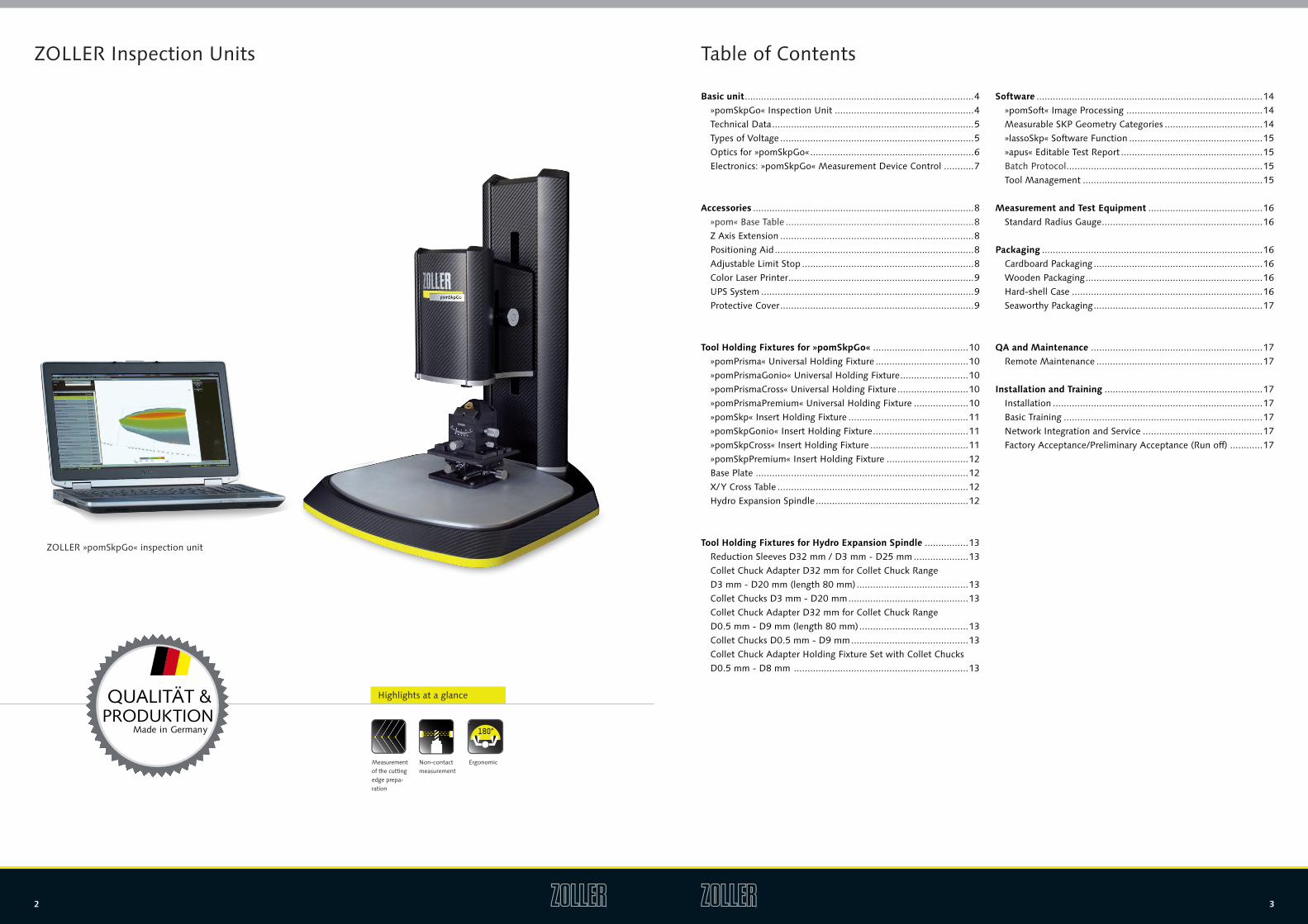
ZOLLER »pomSkpGo« inspection unit
Highlights at a glance
Measurement of the cutting edge prepa-ration
Non-contact measurement
Ergonomic
CNC 180°
4 5
Basic Unit: »pomSkpGo« Inspection Unit
»pomSkpGo« is the inspection unit by ZOLLER for process-orien-ted measurement (»pom«) and inspection of the cutting edge pre-paration on metal cutting tools� The combination of carbon and light-metal components, and the resulting stable machine design, makes »pomSkpGo« the 100% process-oriented and mobile solu-tion� Its compact design allows mobile application and use for in-coming, and final tool inspection in the measurement room, work-shop, or next to the edge preparation machine on the shop floor� Obtain high accurate measuring results within seconds thanks to the easy and quick measuring process of the »pomSkpGo«�
Highlights of »pomSkpGo«: ■ Automatic lighting control and pattern projection ■ Low weight and high rigidity ■ 100 % shop floor-compatible design and suitable for mobile use ■ High level of jop safety ■ Stable aluminum plate with 110 bores in the grid – 30 mm x 30 mm for quick attachment of various tool holding fixtures (Y direction 11 rows and X direction 10 rows)
■ USB 2�0 CCD camera (resolution SXGA 1280 x 1024) ■ Wizard-guided measuring procedures and automatic edge detection
■ Central tool database for storing a wide range of parameters such as ID, character, customer numbers, tool image
»pomSkpGo« SeriesWeight: 20 kg without Hard-Shell Case (12 kg)
Z Axis Working Distance
Minimum Measurable
Radius
LateralResolution
Vertical Resolution Measuring Volume Measuring
Points Measuring Time
»pomSkpGo« with »pomSkpLite« Measuring Sensor
300 mm 30 mm 5 µm 2�5 µm 0�2 µm 1�8 x 1�2 x 1 mm³ 360,000Approximately
12 seconds
»pomSkpGo« with »pomSkpPremium« Measuring Sensor
300 mm 30 mm 3 µm 1�2 µm 0�1 µm 1�6 x 1�2 x 1 mm³ 1�3 millionApproximately
20 seconds
Environment
Humidity Transport and storage 10 % – 95 % non-condensing
Measuring operation 80 % non-condensing
Noise level During normal operation the device reaches a level of < 45 dBA� If adding an optionally availableprinter, this level can rise briefly to approximately 53 dBA, according to DIN 45635�
Electrical Data
Voltage 230 V ± 10 %
Frequency 50/60 Hz ± 2 %
Power < 1000 VA
Circuit Breaker F6A (slow blow)
Technical Data for »pomSkpGo«
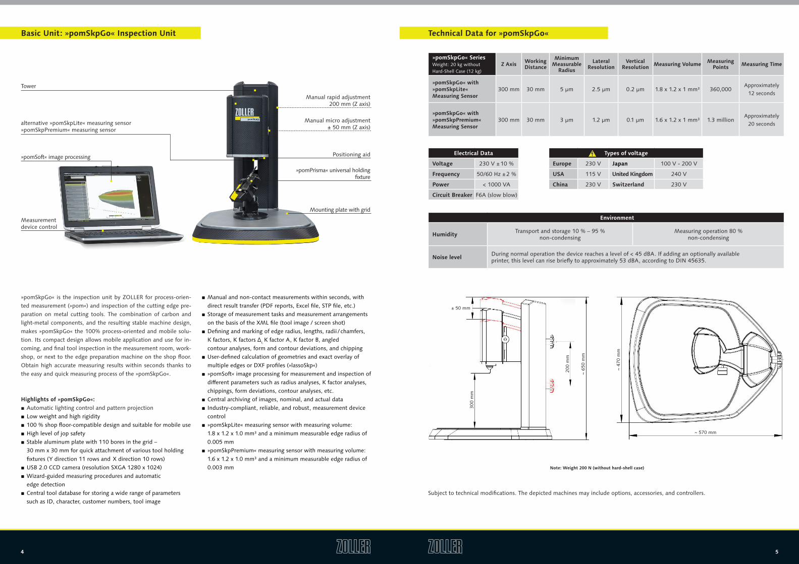
Note: Weight 200 N (without hard-shell case)
Subject to technical modifications� The depicted machines may include options, accessories, and controllers�
■ Manual and non-contact measurements within seconds, with direct result transfer (PDF reports, Excel file, STP file, etc�)
■ Storage of measurement tasks and measurement arrangements on the basis of the XML file (tool image / screen shot)
■ Defining and marking of edge radius, lengths, radii / chamfers, K factors, K factors Δr, K factor A, K factor B, angled contour analyses, form and contour deviations, and chipping
■ User-defined calculation of geometries and exact overlay of multiple edges or DXF profiles (»lassoSkp«)
■ »pomSoft« image processing for measurement and inspection of different parameters such as radius analyses, K factor analyses, chippings, form deviations, contour analyses, etc�
■ Central archiving of images, nominal, and actual data ■ Industry-compliant, reliable, and robust, measurement device control
■ »pomSkpLite« measuring sensor with measuring volume: 1�8 x 1�2 x 1�0 mm³ and a minimum measurable edge radius of 0�005 mm
■ »pomSkpPremium« measuring sensor with measuring volume: 1�6 x 1�2 x 1�0 mm³ and a minimum measurable edge radius of 0�003 mm
Manual rapid adjustment 200 mm (Z axis)
Manual micro adjustment ± 50 mm (Z axis)
»pomPrisma« universal holding fixture
Mounting plate with grid
Positioning aid
Tower
alternative »pomSkpLite« measuring sensor»pomSkpPremium« measuring sensor
»pomSoft« image processing
Measurement device control
Types of voltage
Europe 230 V Japan 100 V - 200 V
USA 115 V United Kingdom 240 V
China 230 V Switzerland 230 V
~ 570 mm
~ 47
0 m
m
~ 65
0 m
m
200
mm
300
mm
± 50 mm
6 7
Optics for »pomSkpGo«
»pomSkpLite«
»pomSkpPremium« Measuring Sensor with DLP Projector and Integrated LED Lighting
Camera Chip Type CCD camera
Measuring Points / Camera Resolution 1�3 million / 1280 x 960 pixels
Measuring Volume (mm³) 1�6 mm x 1�2 mm x 1 mm
Lateral Resolution 1�2 µm
Vertical Resolution 0�1 µm
Measuring Time Approximately 20 seconds
Connection 1 x Ethernet 100 Mbits/s with PoE
Housing Dimensions / Weight 152 mm x 119 mm x 58 mm / approx� 1 kg
»pomSkpPremium«*
The »pomSkpLite« high-resolution measuring sensor detects cutting edge preparation star-ting from a radius of 5 μm on the basis of fringe pattern projection� The integrated white LED lighting and a 752 x 482 pixel telecentric lens allows measurement of the rounding and chipping of cutting edges� To measure the radius of the cutting edge preparation, the cutting edges in front of the sensor must be aligned in the first step� The edge is recorded three-dimensionally and, depending on the setting, the system detects any desired num-ber of profile cross-sections vertically to the edge geometry� For example, the calculation of the chipping is performed in the same way as the roughness parameters Ra and Rmax, where the profile corresponds to the line of the highest points (edge progression of the three-dimensionally aligned height data)�
The »pomSkpPremium« high-resolution measuring sensor detects cutting edge preparati-on starting from a radius of 3 μm on the basis of fringe pattern projection� The integrated blue LED lighting and a 1280 x 960 pixel telecentric lens allows measurement of the rounding and chipping of cutting edges� To measure the radius of the cutting edge prepa-ration, the cutting edges in front of the sensor must be aligned in the first step� The edge is recorded three-dimensionally and, depending on the setting, the system detects any desired number of profile cross-sections vertically to the edge geometry� For example, the calculation of the chipping is performed in the same way as the roughness parameters Ra
and Rmax, where the profile corresponds to the line of the highest points (edge progression of the three-dimensionally aligned height data)�
»pomSkpLite« Measuring Sensor with DLP Projector and Integrated LED Lighting
Camera Chip Type CCD camera
Measuring Points / Camera Resolution 360,000 / 752 pixels x 482 pixels
Measuring Volume (mm³) 1�8 mm x 1�2 mm x 1 mm
Lateral Resolution 2�5 µm
Vertical Resolution 0�2 µm
Measuring Time Approximately 12 seconds
Connection 1 x Ethernet 100 Mbits/s with PoE
Housing Dimensions / Weight 153 mm x 131 mm x 61 mm / approx� 1 kg
*Optional
Electronics: Measurement Device Control for »pomSkpGo«
■ Operating system: Windows 7 64-bit multilingual ■ ZOLLER measurement device control is approved for an ambient temperature of up to 50°C
■ Robust design and manufactured according to CE regulations (Europe) or FCC class B (USA)
■ Tri-Metal™ casing tested according to MIL-STD-810G ■ Encasement made of anodized aluminum and a powder-coated bottom side
■ Low-reflection 15�6-inch Full-HD display with LED backlight ■ Monitoring of the CPU temperature, the computer interior, and the fans using software
■ Fast and shock-resistant solid state disk (SSD) ■ Industrial filter according to EN779 for optimized performance in industrial applications
■ Long-term guaranteed spare part supply despite use of special industrial components
■ 3 years of Pro Support ■ "One-button" data backup for simple backup creation on USB storage devices
■ Optional: All data can be mirrored on a second hard disk via a RAID1 system for increased data security� In case of failure of the first hard disk, the system will automatically switch to the second hard disk so that measurement and operation can be continued without interruption� The defective hard disk can then be replaced at the next opportunity�
Performance and Data
Processor Minimum
Operating System
Working Memory Minimum
Hard Disk
Graphic Card Minimum
Display
Webcam
DVD Burner
Network
Wireless
Interfaces
Power Supply Unit
Intel® CoreTM i7 (4 cores 2�8 GHz each)
Windows® 7 Ultimate 64-bit
8 GB (2 x 4 GB) DDR-3
500 GB SSD Hybrid-HDD 8 GB Flash
Integrated Intel® HD Graphics 4600
15�6-inch Full-HD display (1920 x 1080 pixels)
Integrated HD camera with microphone
DVD-ROM, DVD + / - RW
10/100/1000 Mbits
WLAN 802�11n with Bluetooth 4�0 function
4 x USB 3�0 / VGA / HDMI / RJ-45
Headset / Speaker output
130 watts
Technical data Size
8 9
Accessories for »pomSkpGo«
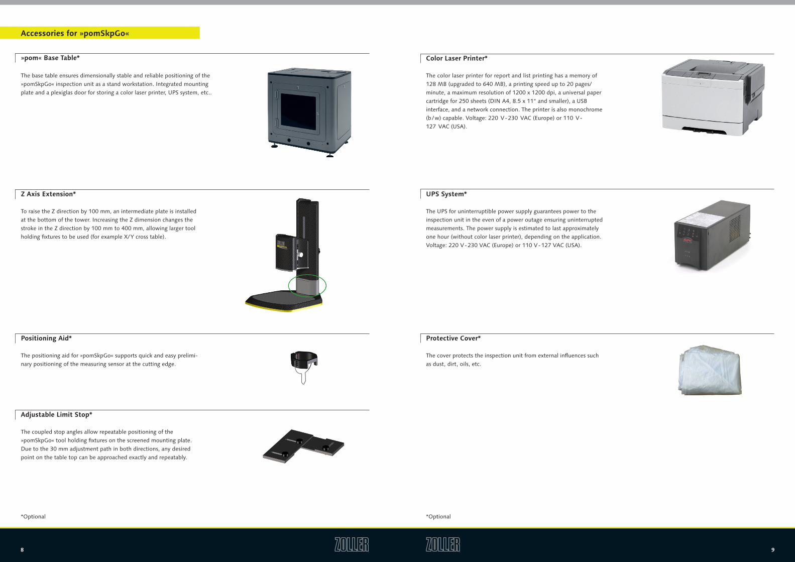
The positioning aid for »pomSkpGo« supports quick and easy prelimi-nary positioning of the measuring sensor at the cutting edge�
Positioning Aid*
The coupled stop angles allow repeatable positioning of the »pomSkpGo« tool holding fixtures on the screened mounting plate� Due to the 30 mm adjustment path in both directions, any desired point on the table top can be approached exactly and repeatably�
Adjustable Limit Stop*
To raise the Z direction by 100 mm, an intermediate plate is installed at the bottom of the tower� Increasing the Z dimension changes the stroke in the Z direction by 100 mm to 400 mm, allowing larger tool holding fixtures to be used (for example X/Y cross table)�
Z Axis Extension*
The cover protects the inspection unit from external influences such as dust, dirt, oils, etc�
Protective Cover*
*Optional *Optional
The color laser printer for report and list printing has a memory of 128 MB (upgraded to 640 MB), a printing speed up to 20 pages/minute, a maximum resolution of 1200 x 1200 dpi, a universal paper cartridge for 250 sheets (DIN A4, 8�5 x 11“ and smaller), a USB interface, and a network connection� The printer is also monochrome (b / w) capable� Voltage: 220 V - 230 VAC (Europe) or 110 V - 127 VAC (USA)�
Color Laser Printer*
The UPS for uninterruptible power supply guarantees power to the inspection unit in the even of a power outage ensuring uninterrupted measurements� The power supply is estimated to last approximately one hour (without color laser printer), depending on the application� Voltage: 220 V - 230 VAC (Europe) or 110 V - 127 VAC (USA)�
UPS System*
»pom« Base Table*
The base table ensures dimensionally stable and reliable positioning of the »pomSkpGo« inspection unit as a stand workstation� Integrated mounting plate and a plexiglas door for storing a color laser printer, UPS system, etc��
10 11
*Optional
Tool Holding Fixtures for »pomSkpGo«
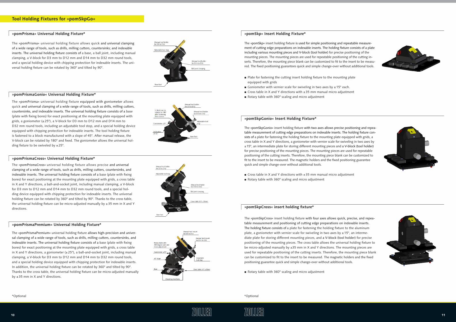
»pomPrisma« Universal Holding Fixture*
»pomPrismaGonio« Universal Holding Fixture*
»pomPrismaCross« Universal Holding Fixture*
The »pomPrisma« universal holding fixture allows quick and universal clamping of a wide range of tools, such as drills, milling cutters, countersinks; and indexable inserts� The universal holding fixture consists of a base, a ball joint, including manual clamping, a V-block for D3 mm to D12 mm and D14 mm to D32 mm round tools, and a special holding device with chipping protection for indexable inserts� The uni-versal holding fixture can be rotated by 360° and tilted by 90°�
The »pomPrisma« universal holding fixture equipped with goniometer allows quick and universal clamping of a wide range of tools, such as drills, milling cutters, countersinks, and indexable inserts� The universal holding fixture consists of a base (plate with fixing bores) for exact positioning at the mounting plate equipped with grids, a goniometer (± 25°), a V-block for D3 mm to D12 mm and D14 mm to D32 mm round tools, including an adjustable tool stop, and a special holding device equipped with chipping protection for indexable inserts� The tool holding fixture is fastened to a block manufactured with a slope of 45°� After manual release, the V-block can be rotated by 180° and fixed� The goniometer allows the universal hol-ding fixture to be swiveled by ± 25°�
The »pomPrismaCross« universal holding fixture allows precise and universal clamping of a wide range of tools, such as drills, milling cutters, countersinks, and indexable inserts� The universal holding fixture consists of a base (plate with fixing bores) for exact positioning at the mounting plate equipped with grids, a cross table in X and Y directions, a ball-and-socket joint, including manual clamping, a V-block for D3 mm to D12 mm and D14 mm to D32 mm round tools, and a special hol-ding device equipped with chipping protection for indexable inserts� The universal holding fixture can be rotated by 360° and tilted by 90°� Thanks to the cross table, the universal holding fixture can be micro-adjusted manually by ± 35 mm in X and Y directions�
»pomPrismaPremium« Universal Holding Fixture*
The »pomPrismaPremium« universal holding fixture allows high-precision and univer-sal clamping of a wide range of tools, such as drills, milling cutters, countersinks, and indexable inserts� The universal holding fixture consists of a base (plate with fixing bores) for exact positioning at the mounting plate equipped with grids, a cross table in X and Y directions, a goniometer (± 25°), a ball-and-socket joint, including manual clamping, a V-block for D3 mm to D12 mm and D14 mm to D32 mm round tools, and a special holding device equipped with chipping protection for indexable inserts� In addition, the universal holding fixture can be rotated by 360° and tilted by 90°� Thanks to the cross table, the universal holding fixture can be micro-adjusted manually by ± 35 mm in X and Y directions�
»pomSkp« Insert Holding Fixture*
The »pomSkp« insert holding fixture is used for simple positioning and repeatable measure-ment of cutting edge preparations on indexable inserts� The holding fixture consists of a plate including various mounting pieces and V-block (tool holder) for precise positioning of the mounting pieces� The mounting pieces are used for repeatable positioning of the cutting in-serts� Therefore, the mounting piece blank can be customized to fit to the insert to be measu-red� The fixed positioning guarantees quick and simple change-over without additional tools�
■ Plate for fastening the cutting insert holding fixture to the mounting plate equipped with grids
■ Goniometer with vernier scale for swiveling in two axes by ± 15° each� ■ Cross table in X and Y directions with ± 35 mm manual micro adjustment ■ Rotary table with 360° scaling and micro adjustment
»pomSkpGonio« Insert Holding Fixture*
The »pomSkpGonio« insert holding fixture with two axes allows precise positioning and repea-table measurement of cutting edge preparations on indexable inserts� The holding fixture con-sists of a plate for fastening the holding fixture to the mounting plate equipped with grids, a cross table in X and Y directions, a goniometer with vernier scale for swiveling in two axes by ± 15°, an intermediate plate for storing different mounting pieces and a V-block (tool holder) for precise positioning of the mounting pieces� The mounting pieces are used for repeatable positioning of the cutting inserts� Therefore, the mounting piece blank can be customized to fit to the insert to be measured� The magnetic holders and the fixed positioning guarantee quick and simple change-over without additional tools�
■ Cross table in X and Y directions with ± 35 mm manual micro adjustment ■ Rotary table with 360° scaling and micro adjustment
»pomSkpCross« insert holding fixture*
The »pomSkpCross« insert holding fixture with four axes allows quick, precise, and repea-table measurement and positioning of cutting edge preparations on indexable inserts� The holding fixture consists of a plate for fastening the holding fixture to the aluminum plate, a goniometer with vernier scale for swiveling in two axes by ± 15°, an interme-diate plate for storing different mounting pieces, and a V-block (tool holder) for precise positioning of the mounting pieces� The cross table allows the universal holding fixture to be micro-adjusted manually by ±35 mm in X and Y directions� The mounting pieces are used for repeatable positioning of the cutting inserts� Therefore, the mounting piece blank can be customized to fit to the insert to be measured� The magnetic holders and the fixed positioning guarantee quick and simple change-over without additional tools�
■ Rotary table with 360° scaling and micro adjustment
*Optional
12 13
*Optional *Optional
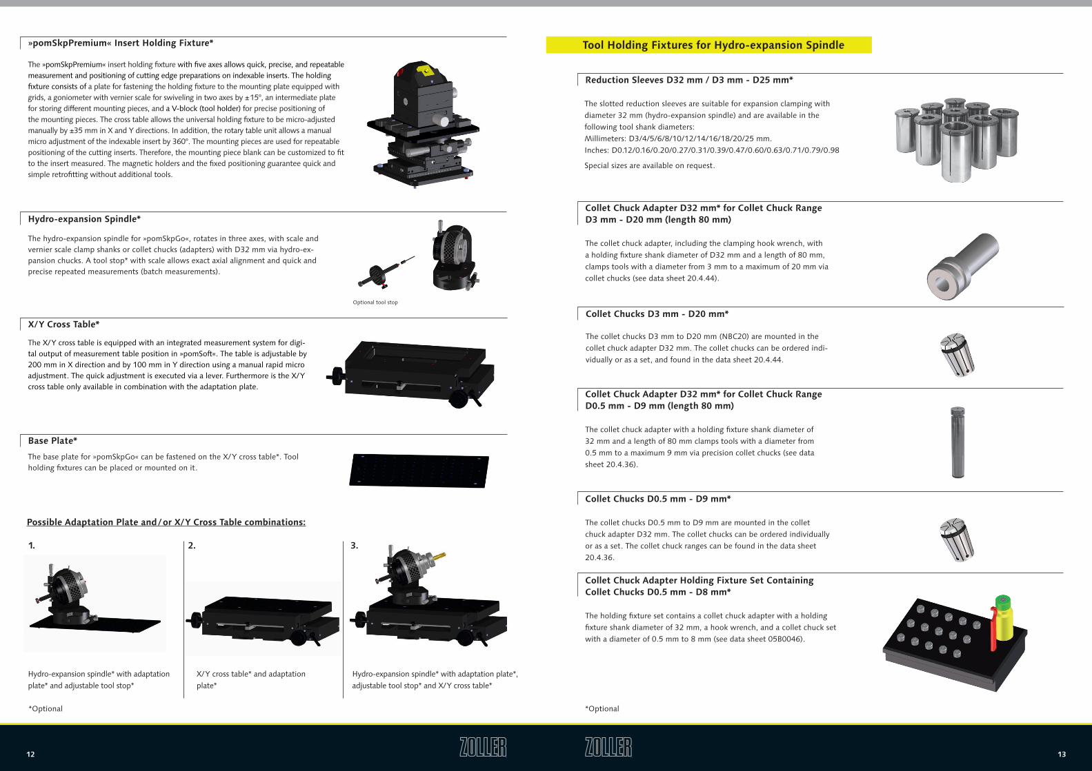
Hydro-expansion Spindle*
The hydro-expansion spindle for »pomSkpGo«, rotates in three axes, with scale and vernier scale clamp shanks or collet chucks (adapters) with D32 mm via hydro-ex-pansion chucks� A tool stop* with scale allows exact axial alignment and quick and precise repeated measurements (batch measurements)�
Optional tool stop
X/Y Cross Table*
The X/Y cross table is equipped with an integrated measurement system for digi-tal output of measurement table position in »pomSoft«� The table is adjustable by 200 mm in X direction and by 100 mm in Y direction using a manual rapid micro adjustment� The quick adjustment is executed via a lever� Furthermore is the X/Y cross table only available in combination with the adaptation plate�
Base Plate*
The base plate for »pomSkpGo« can be fastened on the X/Y cross table*� Tool holding fixtures can be placed or mounted on it�
Possible Adaptation Plate and / or X/Y Cross Table combinations:
1. 2. 3.
Hydro-expansion spindle* with adaptation plate* and adjustable tool stop*
X/Y cross table* and adaptation plate*
Hydro-expansion spindle* with adaptation plate*, adjustable tool stop* and X/Y cross table*
»pomSkpPremium« Insert Holding Fixture*
The »pomSkpPremium« insert holding fixture with five axes allows quick, precise, and repeatable measurement and positioning of cutting edge preparations on indexable inserts� The holding fixture consists of a plate for fastening the holding fixture to the mounting plate equipped with grids, a goniometer with vernier scale for swiveling in two axes by ± 15°, an intermediate plate for storing different mounting pieces, and a V-block (tool holder) for precise positioning of the mounting pieces� The cross table allows the universal holding fixture to be micro-adjusted manually by ±35 mm in X and Y directions� In addition, the rotary table unit allows a manual micro adjustment of the indexable insert by 360°� The mounting pieces are used for repeatable positioning of the cutting inserts� Therefore, the mounting piece blank can be customized to fit to the insert measured� The magnetic holders and the fixed positioning guarantee quick and simple retrofitting without additional tools�
Tool Holding Fixtures for Hydro-expansion Spindle
Reduction Sleeves D32 mm / D3 mm - D25 mm*
The slotted reduction sleeves are suitable for expansion clamping with diameter 32 mm (hydro-expansion spindle) and are available in the following tool shank diameters: Millimeters: D3/4/5/6/8/10/12/14/16/18/20/25 mm� Inches: D0�12/0�16/0�20/0�27/0�31/0�39/0�47/0�60/0�63/0�71/0�79/0�98 Special sizes are available on request�
Collet Chuck Adapter D32 mm* for Collet Chuck Range D0.5 mm - D9 mm (length 80 mm)
The collet chuck adapter with a holding fixture shank diameter of 32 mm and a length of 80 mm clamps tools with a diameter from 0�5 mm to a maximum 9 mm via precision collet chucks (see data sheet 20�4�36)�
Collet Chuck Adapter Holding Fixture Set Containing Collet Chucks D0.5 mm - D8 mm*
The holding fixture set contains a collet chuck adapter with a holding fixture shank diameter of 32 mm, a hook wrench, and a collet chuck set with a diameter of 0�5 mm to 8 mm (see data sheet 05B0046)�
Collet Chuck Adapter D32 mm* for Collet Chuck Range D3 mm - D20 mm (length 80 mm)
Collet Chucks D3 mm - D20 mm*
Collet Chucks D0.5 mm - D9 mm*
The collet chuck adapter, including the clamping hook wrench, with a holding fixture shank diameter of D32 mm and a length of 80 mm, clamps tools with a diameter from 3 mm to a maximum of 20 mm via collet chucks (see data sheet 20�4�44)�
The collet chucks D3 mm to D20 mm (NBC20) are mounted in the collet chuck adapter D32 mm� The collet chucks can be ordered indi-vidually or as a set, and found in the data sheet 20�4�44�
The collet chucks D0�5 mm to D9 mm are mounted in the collet chuck adapter D32 mm� The collet chucks can be ordered individually or as a set� The collet chuck ranges can be found in the data sheet 20�4�36�
14 15
»pomSoft« Image Processing
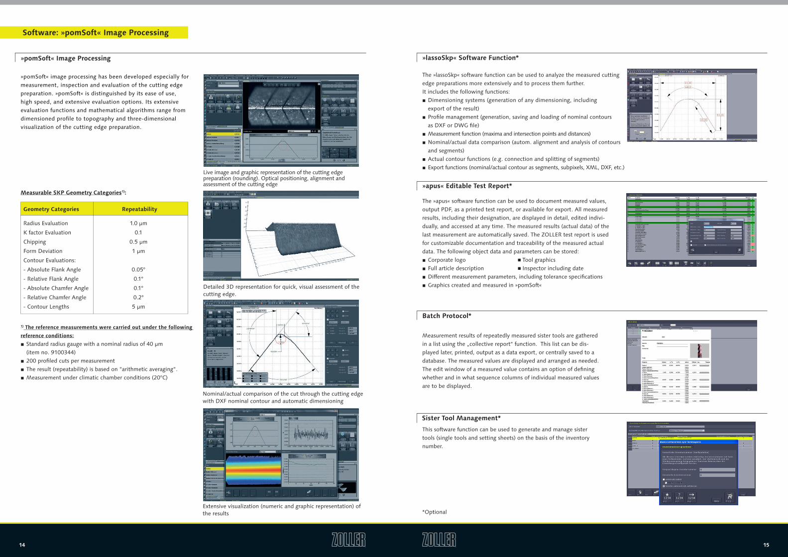
»pomSoft« image processing has been developed especially for measurement, inspection and evaluation of the cutting edge preparation� »pomSoft« is distinguished by its ease of use, high speed, and extensive evaluation options� Its extensive evaluation functions and mathematical algorithms range from dimensioned profile to topography and three-dimensional visualization of the cutting edge preparation�
Measurable SKP Geometry Categories1):
Live image and graphic representation of the cutting edge preparation (rounding)� Optical positioning, alignment and assessment of the cutting edge
Detailed 3D representation for quick, visual assessment of the cutting edge�
Nominal/actual comparison of the cut through the cutting edge with DXF nominal contour and automatic dimensioning
Extensive visualization (numeric and graphic representation) of the results
Software: »pomSoft« Image Processing
»apus« Editable Test Report*
Batch Protocol*
Sister Tool Management*
»lassoSkp« Software Function*
The »apus« software function can be used to document measured values, output PDF, as a printed test report, or available for export� All measured results, including their designation, are displayed in detail, edited indivi-dually, and accessed at any time� The measured results (actual data) of the last measurement are automatically saved� The ZOLLER test report is used for customizable documentation and traceability of the measured actual data� The following object data and parameters can be stored:
■ Corporate logo n Tool graphics ■ Full article description n Inspector including date ■ Different measurement parameters, including tolerance specifications ■ Graphics created and measured in »pomSoft«
Measurement results of repeatedly measured sister tools are gathered in a list using the „collective report“ function� This list can be dis-played later, printed, output as a data export, or centrally saved to a database� The measured values are displayed and arranged as needed� The edit window of a measured value contains an option of defining whether and in what sequence columns of individual measured values are to be displayed�
This software function can be used to generate and manage sister tools (single tools and setting sheets) on the basis of the inventory number�
The »lassoSkp« software function can be used to analyze the measured cutting edge preparations more extensively and to process them further� It includes the following functions:
■ Dimensioning systems (generation of any dimensioning, including export of the result)
■ Profile management (generation, saving and loading of nominal contours as DXF or DWG file)
■ Measurement function (maxima and intersection points and distances) ■ Nominal/actual data comparison (autom� alignment and analysis of contours and segments)
■ Actual contour functions (e�g� connection and splitting of segments) ■ Export functions (nominal/actual contour as segments, subpixels, XML, DXF, etc�)
*Optional
1) The reference measurements were carried out under the following
reference conditions:
■ Standard radius gauge with a nominal radius of 40 µm (item no� 9100344)
■ 200 profiled cuts per measurement ■ The result (repeatability) is based on "arithmetic averaging"� ■ Measurement under climatic chamber conditions (20°C)
Radius Evaluation
K factor Evaluation
Chipping
Form Deviation
Contour Evaluations:
- Absolute Flank Angle
- Relative Flank Angle
- Absolute Chamfer Angle
- Relative Chamfer Angle
- Contour Lengths
1�0 µm
0�1
0�5 µm
1 µm
0�05°
0�1°
0�1°
0�2°
5 µm
Geometry Categories Repeatability
16 17
*Optional *Optional
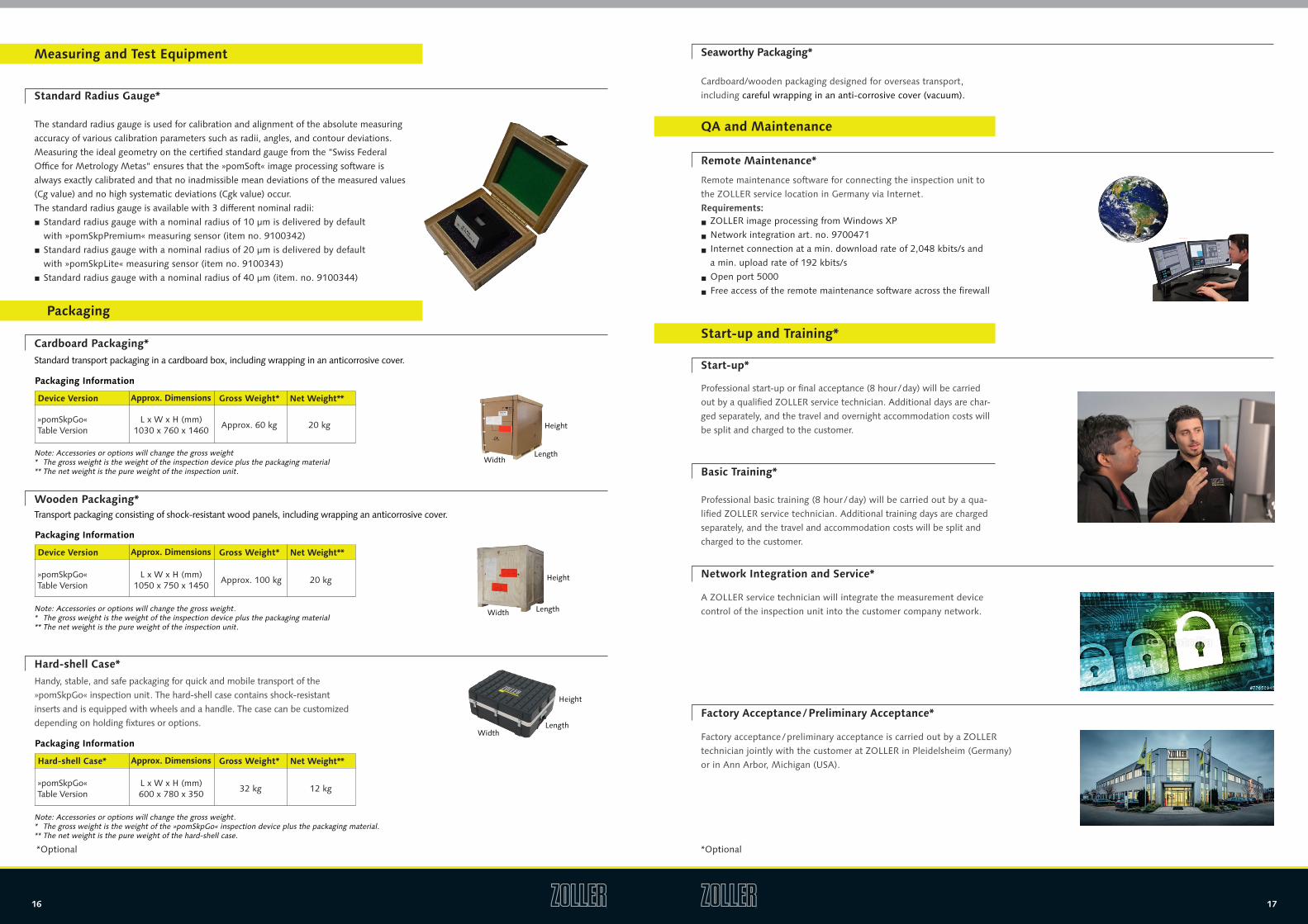
Standard Radius Gauge*
The standard radius gauge is used for calibration and alignment of the absolute measuring accuracy of various calibration parameters such as radii, angles, and contour deviations� Measuring the ideal geometry on the certified standard gauge from the "Swiss Federal Office for Metrology Metas" ensures that the »pomSoft« image processing software is always exactly calibrated and that no inadmissible mean deviations of the measured values (Cg value) and no high systematic deviations (Cgk value) occur�The standard radius gauge is available with 3 different nominal radii:
■ Standard radius gauge with a nominal radius of 10 µm is delivered by default with »pomSkpPremium« measuring sensor (item no� 9100342)
■ Standard radius gauge with a nominal radius of 20 µm is delivered by default with »pomSkpLite« measuring sensor (item no� 9100343)
■ Standard radius gauge with a nominal radius of 40 µm (item� no� 9100344)
Measuring and Test Equipment
Hard-shell Case*Handy, stable, and safe packaging for quick and mobile transport of the »pomSkpGo« inspection unit� The hard-shell case contains shock-resistant inserts and is equipped with wheels and a handle� The case can be customized depending on holding fixtures or options�
Packaging
Cardboard Packaging*
Wooden Packaging*
Standard transport packaging in a cardboard box, including wrapping in an anticorrosive cover�
Note: Accessories or options will change the gross weight** The gross weight is the weight of the inspection device plus the packaging material** The net weight is the pure weight of the inspection unit�
Transport packaging consisting of shock-resistant wood panels, including wrapping an anticorrosive cover�
Packaging Information
Device Version Gross Weight*Approx. Dimensions Net Weight**
Note: Accessories or options will change the gross weight�** The gross weight is the weight of the inspection device plus the packaging material** The net weight is the pure weight of the inspection unit�
L x W x H (mm)1050 x 750 x 1450
»pomSkpGo« Table Version
Packaging Information
Device Version Gross Weight*Approx. Dimensions Net Weight**
Approx� 100 kg 20 kg
Note: Accessories or options will change the gross weight�** The gross weight is the weight of the »pomSkpGo« inspection device plus the packaging material�** The net weight is the pure weight of the hard-shell case�
L x W x H (mm)600 x 780 x 350
»pomSkpGo« Table Version
Packaging Information
Hard-shell Case* Gross Weight*Approx. Dimensions Net Weight**
32 kg 12 kg
WidthLength
Height
Width
Width
Length
Length
Height
Height
Seaworthy Packaging*
Cardboard/wooden packaging designed for overseas transport, including careful wrapping in an anti-corrosive cover (vacuum)�
Start-up and Training*
Start-up*
Basic Training*
Network Integration and Service*
Factory Acceptance / Preliminary Acceptance*
Professional start-up or final acceptance (8 hour / day) will be carried out by a qualified ZOLLER service technician� Additional days are char-ged separately, and the travel and overnight accommodation costs will be split and charged to the customer�
A ZOLLER service technician will integrate the measurement device control of the inspection unit into the customer company network�
Factory acceptance / preliminary acceptance is carried out by a ZOLLER technician jointly with the customer at ZOLLER in Pleidelsheim (Germany) or in Ann Arbor, Michigan (USA)�
Professional basic training (8 hour / day) will be carried out by a qua-lified ZOLLER service technician� Additional training days are charged separately, and the travel and accommodation costs will be split and charged to the customer�
QA and Maintenance
Remote Maintenance*
Remote maintenance software for connecting the inspection unit to the ZOLLER service location in Germany via Internet� Requirements:
■ ZOLLER image processing from Windows XP
■ Network integration art� no� 9700471
■ Internet connection at a min� download rate of 2,048 kbits/s and a min� upload rate of 192 kbits/s
■ Open port 5000
■ Free access of the remote maintenance software across the firewall
L x W x H (mm)1030 x 760 x 1460
»pomSkpGo« Table Version
Approx� 60 kg 20 kg
Rev
� 201
6-01
-13/
tr (
ci_T
BPSK
P�00
-EN
) Su
bjec
t to
tec
hnic
al m
odifi
cati
ons�
E� Zoller GmbH & Co� KG | Presetter and Measuring Machines
Gottlieb-Daimler-Straße 19 | D-74385 Pleidelsheim
Phone: +49 7144 8970-0 | Fax: +49 7144 8060-807
post@zoller�info
www�zoller�info
ZOLLER solutions
ZOLLER solutions are synonymous with comprehensive optimization of your manufacturing operations� ZOLLER combines hardware, software and services to customized system solu-tions to improve quality, efficiency and productivity� As a ZOLLER customer you benefit not only from our know-how as market leader in the field of tool measurement technology, but equally from our claim as a family-run business, guaranteeing you sustainable competitive advantages and thus making a measurable contribution to your success�
PRESETTING SOLUTIONSPresetting & measuring Managing tools
Inspection & measuring from A-ZINSPECTION SOLUTIONS
SOFTWARE SOLUTIONS
BUSINESS SOLUTIONS


![C R E D I T S - thetrove.is [multi]/Naruto (d20)/d20-Naruto... · This Naruto: d20 supplement is designed for use with the Naruto d20 and d20 Modern Roleplaying Game published by](https://img.pdfslide.net/doc/110x75/60afa37945ac8908e62fd7cc/c-r-e-d-i-t-s-multinaruto-d20d20-naruto-this-naruto-d20-supplement.jpg)