Embed Size (px)
Citation preview
Revised 02/06 1
TECHNICAL INFORMATION FOR CDM4161
Technical Information for the CDM4161 CO 2 Module
PageBasic Information and Specifications
Features.....................................................................................................2Applications.............................................................................................2Specifications.....................................................................................2Dimensions..........................................................................................2
Structure and functionsSolid electrolyte CO2 sensor TGS4161.....................................................2Sensor's output signal voltage (CP3)........................................................2Variable resistor (VR1)...............................................................................2Thermistor signal output voltage (CP4).................................................2Microcomputer........................................................................................2Concentration setting for system control (JP3, JP4)................................2Baseline reset switch...............................................................................4Input-output signal (CN1)....................................................................4LEDs..........................................................................................................4
Operation modesWarm up...............................................................................................5CO2 concentration lower than calibrated concentration.......................5CO2 concetration exceeds calibrated concentration...............................5Trouble..............................................................................................5
Cautions...............................................................................................5Important Notice..............................................................................................6
an I
SO90
01 a
nd 1
4001
com
pany
IMPORTANT NOTE: OPERATING CONDITIONS IN WHICH FIGARO SENSORS ARE USED WILL VARYWITH EACH CUSTOMER’S SPECIFIC APPLICATIONS. FIGARO STRONGLY RECOMMENDSCONSULTING OUR TECHNICAL STAFF BEFORE DEPLOYING FIGARO SENSORS IN YOUR APPLICATIONAND, IN PARTICULAR, WHEN CUSTOMER’S TARGET GASES ARE NOT LISTED HEREIN. FIGAROCANNOT ASSUME ANY RESPONSIBILITY FOR ANY USE OF ITS SENSORS IN A PRODUCT ORAPPLICATION FOR WHICH SENSOR HAS NOT BEEN SPECIFICALLY TESTED BY FIGARO.
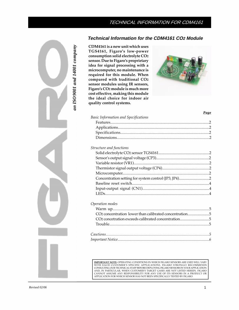
CDM4161 is a new unit which usesTGS4161, Figaro's low-powerconsumption solid electrolyte CO2
sensor. Due to Figaro’s proprietaryidea for signal processing with amicrocomputer, no maintenance isrequired for this module. Whencompared with traditional CO2
sensor modules using IR sensors,Figaro’s CO2 module is much morecost effective, making this modulethe ideal choice for indoor airquality control systems.
Revised 02/06 2
TECHNICAL INFORMATION FOR CDM4161
1. Basic Information
1-1 Features
* High selectivity to CO2
* Maintenance free* Low power consumption* Long life* Compact size* Pre-calibrated* Low cost
1-2 Applications
* Indoor air quality control* CO2 monitors
1-3 Specifications
The specifications of CDM4161 are containedin Table 1. Depending on the customer's targetconcentration range, Figaro offers two versionsof this module as indicated in Table 1.Customized modules are available accordingto special requests from customers. Pleaseconsult with Figaro.
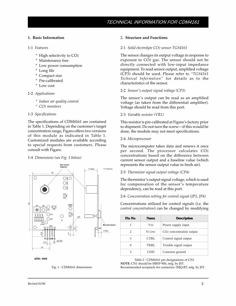
1-4 Dimensions (see Fig. 1 below)
Fig. 1 - CDM4161 dimensions
.oNniP .oNniP .oNniP .oNniP .oNniP emaN emaN emaN emaN emaN noitpircseD noitpircseD noitpircseD noitpircseD noitpircseD
1 V NI tupniylppusrewoP
2 V CNOC OC 2 tuptuonoitartnecnoc
3 LRTC tuptuolangislortnoC
4 LBRT tuptuolangiselbuorT
5 DNG dnuorgnommoC
Table 2 - CDM4161 pin designations of CN1NOTE: CN1 should be MB5P-90S, mfg. by JST.Recommended receptacle for connector: 05JQ-BT, mfg. by JST.
u/m: mm
2. Structure and Functions
2-1 Solid electrolyte CO2 sensor TGS4161
The sensor changes its output voltage in response toexposure to CO2 gas. The sensor should not bedirectly connected with low-input impedanceequipment. To read sensor output, amplified voltage(CP3) should be used. Please refer to “TGS4161Technical Information” for details as to thecharacteristics of the sensor.
2-2 Sensor's output signal voltage (CP3)
The sensor’s output can be read as an amplifiedvoltage (as taken from the differential amplifier).Voltage should be read from this port.
2-3 Variable resistor (VR1)
This resistor is pre-calibrated at Figaro’s factory priorto shipment. Do not turn the screw—if this would bedone, the module may not meet specifications.
2-4 Microprocessor
The microcomputer takes data and renews it onceper second. The processor calculates CO2concentrations based on the difference betweencurrent sensor output and a baseline value (whichrepresents the sensor output value in fresh air).
2-5 Thermistor signal output voltage (CP4)
The thermistor’s output signal voltage, which is usedfor compensation of the sensor ’s temperaturedependency, can be read at this port.
2-6 Concentration setting for control signal (JP3, JP4)
Concentrations utilized for control signals (i.e. thecontrol concentration) can be changed by modifying
CP3
CP5
SW1
CP4
CP2
CP1
[+5V]
[GND]
LE
D1
LE
D2
LE
D3
JP1
JP5
JP2
JP3
JP4
JP6
JP7
CN1
12345
45
60
+VR1
Gas sensor TGS4161
3
ø3
14 Max t=1.6(mm)
3 Max
Microprocessor
C2
3
19
2.5ø0.64
6.9
Revised 02/06 3
TECHNICAL INFORMATION FOR CDM4161
VINVDD
VSS
6
5 4
8
1
2
3
4
5
ConnectorMB5P-90S
11
7
3
5
4
2
1
6
2208
9
5
14
D/AConverter
VCONC
CTRL
TRBL
GND
Microcomputer
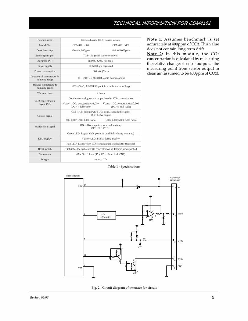
Fig. 2 - Circuit diagram of interface for circuit
Table 1 - Specifications
emantcudorP OC(edixoidnobraC 2 eludomrosnes)
.oNledoM 00L-1614MDC 00M-1614MDC
egnarnoitceteD mpp000,4ot004 mpp000,8ot004
)elpicnirp(rosneS )etylortceleetatsdilos(1614SGT
)1*(ycaruccA .xorppa ± elacslluf%02
ylppusrewoP 0.5CD ± detalugerV2.0
noitpmusnocrewoP )xaM(Wm003
&erutarepmetlanoitarepOegnarytidimuh
)noitasnednocdiova(HR%59~5,C˚05+~˚01-
&erutarepmetegarotSegnarytidimuh
)gabfoorperutsiomanikcap(HR%09~5,C˚06+~˚02-
emitpumraW sruoh2
noitartnecnoc2OC)2*(langis
OCotlanoitroporptuptuogolanasuounitnoC 2 noitartnecnoc
OC=cnocV 2 000,1/noitartnecnoc)elacsllufV4CD(
OC=cnocV 2 000,2/noitartnecnoc)elacsllufV4CD(
langislortnoC
OCnehw(tuptuoHGIH:NO 2 )dlohserhtsdeecxe.cnoctuptuoWOL:FFO
)mpp(000,2/005,1/000,1/008 )mpp(000,8/000,5/000,2/000,1
langisnoitcnuflaM)noitcnuflamrosnes(tuptuoWOL:NO
CNTAOLF:FFO
yalpsidDEL
)pumrawgnirudsknilb(nosirewopelihwsthgiL:DELneerG
elbuortgnirudsknilB:DELwolleY
OCnehwsthgiL:DELdeR 2 dlohserhtehtsdeecxenoitartnecnoc
hctiwsteseR OCtneibmaehtsehsilbatsE 2 dehsupnehwmpp004sanoitartnecnoc
snoisnemiD )1NC.lcnimm91x76x54(mm91x06x54
thgieW g71.xorppa
Note 1: Assumes benchmark is setaccuractely at 400ppm of CO2. This valuedoes not contain long term drift.Note 2: In this module, the CO2concentration is calculated by measuringthe relative change of sensor output at themeasuring point from sensor output inclean air (assumed to be 400ppm of CO2).
Revised 02/06 4
TECHNICAL INFORMATION FOR CDM4161
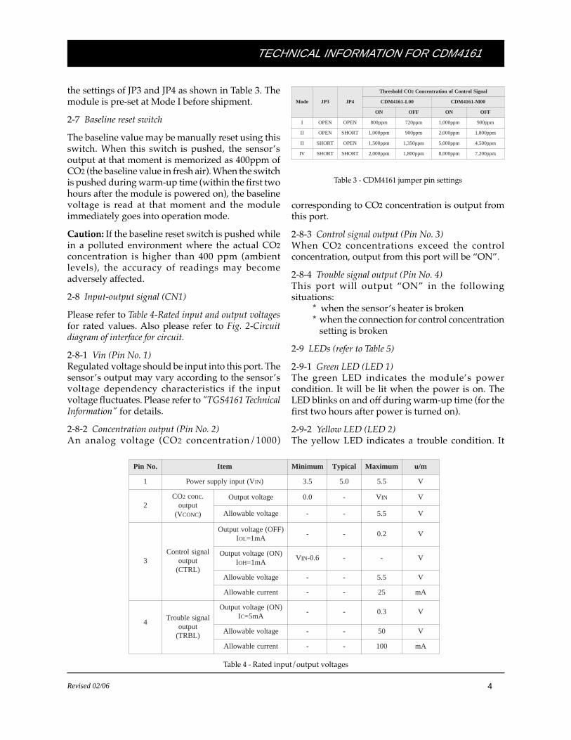
the settings of JP3 and JP4 as shown in Table 3. Themodule is pre-set at Mode I before shipment.
2-7 Baseline reset switch
The baseline value may be manually reset using thisswitch. When this switch is pushed, the sensor’soutput at that moment is memorized as 400ppm ofCO2 (the baseline value in fresh air). When the switchis pushed during warm-up time (within the first twohours after the module is powered on), the baselinevoltage is read at that moment and the moduleimmediately goes into operation mode.
Caution: If the baseline reset switch is pushed whilein a polluted environment where the actual CO2concentration is higher than 400 ppm (ambientlevels), the accuracy of readings may becomeadversely affected.
2-8 Input-output signal (CN1)
Please refer to Table 4-Rated input and output voltagesfor rated values. Also please refer to Fig. 2-Circuitdiagram of interface for circuit.
2-8-1 Vin (Pin No. 1)Regulated voltage should be input into this port. Thesensor’s output may vary according to the sensor’svoltage dependency characteristics if the inputvoltage fluctuates. Please refer to "TGS4161 TechnicalInformation" for details.
2-8-2 Concentration output (Pin No. 2)An analog voltage (CO2 concentration/1000)
Table 4 - Rated input/output voltages
.oNniP metI muminiM lacipyT mumixaM m/u
1 V(tupniylppusrewoP NI ) 5.3 0.5 5.5 V
2OC 2 .cnoc
tuptuoV( CNOC )
egatlovtuptuO 0.0 - V NI V
egatlovelbawollA - - 5.5 V
3langislortnoC
tuptuo)LRTC(
)FFO(egatlovtuptuOI LO Am1=
- - 2.0 V
)NO(egatlovtuptuOI HO Am1=
V NI 6.0- - - V
egatlovelbawollA - - 5.5 V
tnerrucelbawollA - - 52 Am
4langiselbuorT
tuptuo)LBRT(
)NO(egatlovtuptuOIC Am5=
- - 3.0 V
egatlovelbawollA - - 05 V
tnerrucelbawollA - - 001 Am
edoM 3PJ 4PJ
OCdlohserhT 2 langiSlortnoCfonoitartnecnoC
00L-1614MDC 00M-1614MDC
NO FFO NO FFO
I NEPO NEPO mpp008 mpp027 mpp000,1 mpp009
II NEPO TROHS mpp000,1 mpp009 mpp000,2 mpp008,1
II TROHS NEPO mpp005,1 mpp053,1 mpp000,5 mpp005,4
VI TROHS TROHS mpp000,2 mpp008,1 mpp000,8 mpp002,7
Table 3 - CDM4161 jumper pin settings
corresponding to CO2 concentration is output fromthis port.
2-8-3 Control signal output (Pin No. 3)When CO2 concentrations exceed the controlconcentration, output from this port will be “ON”.
2-8-4 Trouble signal output (Pin No. 4)This port will output “ON” in the followingsituations:
* when the sensor’s heater is broken* when the connection for control concentration
setting is broken
2-9 LEDs (refer to Table 5)
2-9-1 Green LED (LED 1)The green LED indicates the module’s powercondition. It will be lit when the power is on. TheLED blinks on and off during warm-up time (for thefirst two hours after power is turned on).
2-9-2 Yellow LED (LED 2)The yellow LED indicates a trouble condition. It
Revised 02/06 5
TECHNICAL INFORMATION FOR CDM4161
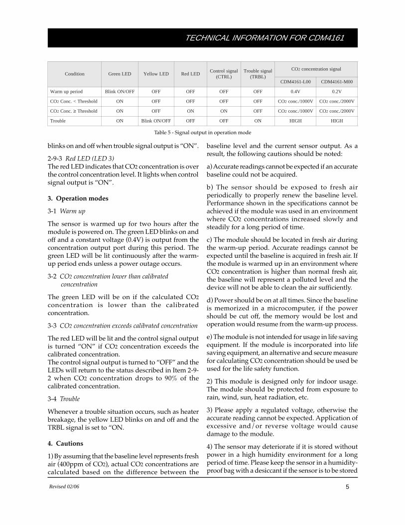
noitidnoC DELneerG DELwolleY DELdeRlangislortnoC
)LRTC(langiselbuorT
)LBRT(
OC 2 langisnoitartnecnoc
00L-1614MDC 00M-1614MDC
doireppumraW FFO/NOknilB FFO FFO FFO FFO V4.0 V2.0
OC 2 dlohserhT<.cnoC NO FFO FFO FFO FFO OC 2 V0001/.cnoc OC 2 V0002/.cnoc
OC 2 .cnoC ≥ dlohserhT NO FFO NO NO FFO OC 2 V0001/.cnoc OC 2 V0002/.cnoc
elbuorT NO FFO/NOknilB FFO FFO NO HGIH HGIH
Table 5 - Signal output in operation mode
blinks on and off when trouble signal output is “ON”.
2-9-3 Red LED (LED 3)The red LED indicates that CO2 concentration is overthe control concentration level. It lights when controlsignal output is “ON”.
3. Operation modes
3-1 Warm up
The sensor is warmed up for two hours after themodule is powered on. The green LED blinks on andoff and a constant voltage (0.4V) is output from theconcentration output port during this period. Thegreen LED will be lit continuously after the warm-up period ends unless a power outage occurs.
3-2 CO2 concentration lower than calibrated concentration
The green LED will be on if the calculated CO2concentration is lower than the calibratedconcentration.
3-3 CO2 concentration exceeds calibrated concentration
The red LED will be lit and the control signal outputis turned “ON” if CO2 concentration exceeds thecalibrated concentration.The control signal output is turned to “OFF” and theLEDs will return to the status described in Item 2-9-2 when CO2 concentration drops to 90% of thecalibrated concentration.
3-4 Trouble
Whenever a trouble situation occurs, such as heaterbreakage, the yellow LED blinks on and off and theTRBL signal is set to “ON.
4. Cautions
1) By assuming that the baseline level represents freshair (400ppm of CO2), actual CO2 concentrations arecalculated based on the difference between the
baseline level and the current sensor output. As aresult, the following cautions should be noted:
a) Accurate readings cannot be expected if an accuratebaseline could not be acquired.
b) The sensor should be exposed to fresh airperiodically to properly renew the baseline level.Performance shown in the specifications cannot beachieved if the module was used in an environmentwhere CO2 concentrations increased slowly andsteadily for a long period of time.
c) The module should be located in fresh air duringthe warm-up period. Accurate readings cannot beexpected until the baseline is acquired in fresh air. Ifthe module is warmed up in an environment whereCO2 concentration is higher than normal fresh air,the baseline will represent a polluted level and thedevice will not be able to clean the air sufficiently.
d) Power should be on at all times. Since the baselineis memorized in a microcomputer, if the powershould be cut off, the memory would be lost andoperation would resume from the warm-up process.
e) The module is not intended for usage in life savingequipment. If the module is incorporated into lifesaving equipment, an alternative and secure measurefor calculating CO2 concentration should be used beused for the life safety function.
2) This module is designed only for indoor usage.The module should be protected from exposure torain, wind, sun, heat radiation, etc.
3) Please apply a regulated voltage, otherwise theaccurate reading cannot be expected. Application ofexcessive and/or reverse voltage would causedamage to the module.
4) The sensor may deteriorate if it is stored withoutpower in a high humidity environment for a longperiod of time. Please keep the sensor in a humidity-proof bag with a desiccant if the sensor is to be stored

Revised 02/06 6
TECHNICAL INFORMATION FOR CDM4161
FIGARO GROUP
HEAD OFFICE
Figaro Engineering Inc.1-5-11 Senba-nishiMino, Osaka 562-8505 JAPANTel.: (81) 72-728-2561Fax: (81) 72-728-0467email: [email protected]
OVERSEAS
Figaro USA Inc.3703 West Lake Ave. Suite 203Glenview, IL 60026 USATel.: (1) 847-832-1701Fax.: (1) 847-832-1705email: [email protected]
without power for a long period of time.
5) Please refer to “TGS4161 Technical Information” forother handling precautions of TGS4161.
5. Important Notice
Figaro Engineering Inc. (Figaro) reserves the right tomake changes without notice to any products hereinto improve reliability, functioning or design.
Information contained in this document is believedto be reliable. However, Figaro does not assume anyliability arising out of the application or use of anyproduct or circuit described herein; neither does itconvey any license under its patent rights, nor therights of others.
IMPORTANT NOTEThis product is not designed and authorized for useas a component in life support applications whereina failure or malfunction of the products may resultin injury or threat to life. Figaro Engineering Inc.reserves the right to make changes to this productwithout notice to improve reliability, functioning,and/or design.