Embed Size (px)
Citation preview

GN ReSound as Global Technical Operations
http://gto.gnresound.comLautrupbjerg 7 • DK-2750 Ballerup • Denmark
Technical ManualReSound Sydney Platform BTE
Doc 0197030 rev. J
Page 2 of 29
Not subject to issue control when printed
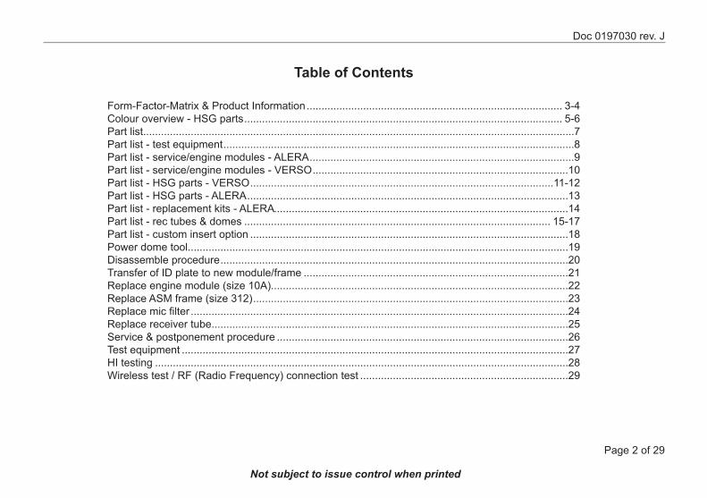
Table of Contents
Form-Factor-Matrix & Product Information ...................................................................................... 3-4Colour overview - HSG parts ........................................................................................................... 5-6Part list.................................................................................................................................................7Part list - test equipment ......................................................................................................................8Part list - service/engine modules - ALERA .........................................................................................9Part list - service/engine modules - VERSO ......................................................................................10Part list - HSG parts - VERSO ......................................................................................................11-12Part list - HSG parts - ALERA ............................................................................................................13Part list - replacement kits - ALERA...................................................................................................14Part list - rec tubes & domes ....................................................................................................... 15-17Part list - custom insert option ...........................................................................................................18Power dome tool................................................................................................................................19Disassemble procedure .....................................................................................................................20Transfer of ID plate to new module/frame .........................................................................................21Replace engine module (size 10A)....................................................................................................22Replace ASM frame (size 312) ..........................................................................................................23Replace mic filter ...............................................................................................................................24Replace receiver tube........................................................................................................................25Service & postponement procedure ..................................................................................................26Test equipment ..................................................................................................................................27HI testing ...........................................................................................................................................28Wireless test / RF (Radio Frequency) connection test ......................................................................29
Doc 0197030 rev. J
Page 3 of 29
Not subject to issue control when printed
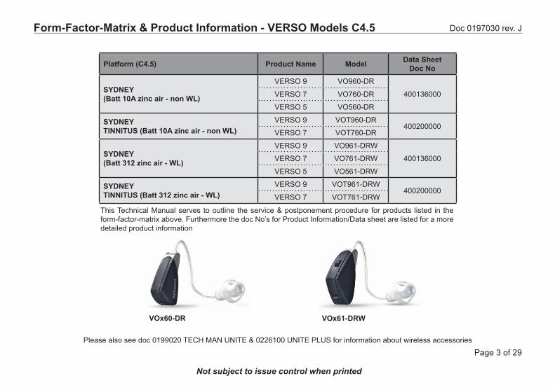
Form-Factor-Matrix & Product Information - VERSO Models C4.5
Platform (C4.5) Product Name Model Data SheetDoc No
SYDNEY (Batt 10A zinc air - non WL)
VERSO 9 VO960-DR
400136000VERSO 7 VO760-DR
VERSO 5 VO560-DR
SYDNEY TINNITUS (Batt 10A zinc air - non WL)
VERSO 9 VOT960-DR400200000
VERSO 7 VOT760-DR
SYDNEY (Batt 312 zinc air - WL)
VERSO 9 VO961-DRW
400136000VERSO 7 VO761-DRW
VERSO 5 VO561-DRW
SYDNEY TINNITUS (Batt 312 zinc air - WL)
VERSO 9 VOT961-DRW400200000
VERSO 7 VOT761-DRW
Please also see doc 0199020 TECH MAN UNITE & 0226100 UNITE PLUS for information about wireless accessories
VOx60-DR VOx61-DRW
This Technical Manual serves to outline the service & postponement procedure for products listed in the form-factor-matrix above. Furthermore the doc No’s for Product Information/Data sheet are listed for a more detailed product information
Doc 0197030 rev. J
Page 4 of 29
Not subject to issue control when printed
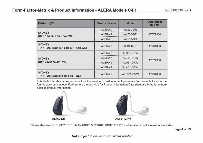
Form-Factor-Matrix & Product Information - ALERA Models C4.1
This Technical Manual serves to outline the service & postponement procedure for products listed in the form-factor-matrix above. Furthermore the doc No’s for Product Information/Data sheet are listed for a more detailed product information
ALx60-DR ALx61-DRW
Platform (C4.1) Product Name Model Data SheetDoc No
SYDNEY (Batt 10A zinc air - non WL)
ALERA 9 AL960-DR
17377900ALERA 7 AL760-DR
ALERA 5 AL560-DR
SYDNEY TINNITUS (Batt 10A zinc air - non WL) ALERA 9 ALT960-DR 17734800
SYDNEY (Batt 312 zinc air - WL)
ALERA 9 AL961-DRW
17377900ALERA 7 AL761-DRW
ALERA 5 AL561-DRW
ALERA 4 AL461-DRW
SYDNEY TINNITUS (Batt 312 zinc air - WL) ALERA 9 ALT961-DRW 17734800
Please also see doc 0199020 TECH MAN UNITE & 0226100 UNITE PLUS for information about wireless accessories
Doc 0197030 rev. J
Page 5 of 29
Not subject to issue control when printed
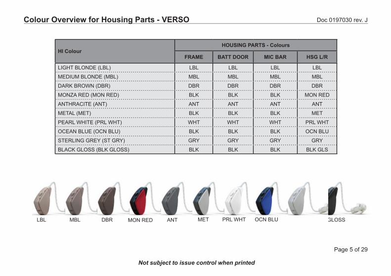
HI ColourHOUSING PARTS - Colours
FRAME BATT DOOR MIC BAR HSG L/R
LIGHT BLONDE (LBL) LBL LBL LBL LBL
MEDIUM BLONDE (MBL) MBL MBL MBL MBL
DARK BROWN (DBR) DBR DBR DBR DBR
MONZA RED (MON RED) BLK BLK BLK MON RED
ANTHRACITE (ANT) ANT ANT ANT ANT
METAL (MET) BLK BLK BLK MET
PEARL WHITE (PRL WHT) WHT WHT WHT PRL WHT
OCEAN BLUE (OCN BLU) BLK BLK BLK OCN BLU
STERLING GREY (ST GRY) GRY GRY GRY GRY
BLACK GLOSS (BLK GLOSS) BLK BLK BLK BLK GLS
Colour Overview for Housing Parts - VERSO
MBL DBR BLK GLOSSST GRYLBL MON RED ANT MET PRL WHT OCN BLU
Doc 0197030 rev. J
Page 6 of 29
Not subject to issue control when printed
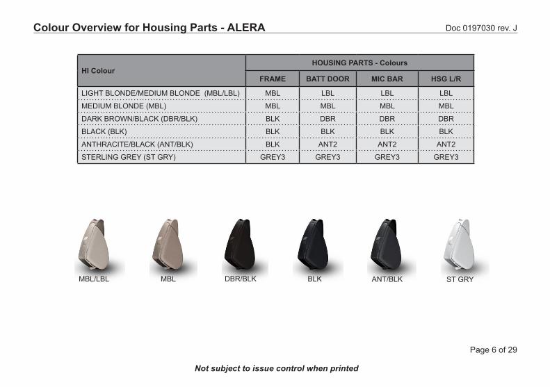
HI ColourHOUSING PARTS - Colours
FRAME BATT DOOR MIC BAR HSG L/R
LIGHT BLONDE/MEDIUM BLONDE (MBL/LBL) MBL LBL LBL LBL
MEDIUM BLONDE (MBL) MBL MBL MBL MBL
DARK BROWN/BLACK (DBR/BLK) BLK DBR DBR DBR
BLACK (BLK) BLK BLK BLK BLK
ANTHRACITE/BLACK (ANT/BLK) BLK ANT2 ANT2 ANT2
STERLING GREY (ST GRY) GREY3 GREY3 GREY3 GREY3
MBL/LBL MBL DBR/BLK BLK ANT/BLK ST GRY
Colour Overview for Housing Parts - ALERA
Doc 0197030 rev. J
Page 7 of 29
Not subject to issue control when printed
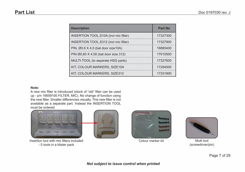
Part List
Description Part No
INSERTION TOOL,S10A (incl mic filter) 17327300
INSERTION TOOL,S312 (incl mic filter) 17327900
PIN, Ø0.6 X 4.0 (bat door size10A) 16885400
PIN Ø0,60 X 4,50 (bat door size 312) 17010500
MULTI-TOOL (to separate HSG parts) 17327600
KIT, COLOUR MARKERS, SIZE10A 17294500
KIT, COLOUR MARKERS, SIZE312 17331900
Multi tool(screwdriver/pin)
Insertion tool with mic filters included - 5 tools in a blister pack
Colour marker kit
Note:A new mic filter is introduced (stock of “old” filter can be used up - p/n 16659100 FILTER, MIC). No change of function using the new filter. Smaller differencies visually. This new filter is not available as a separate part. Instead the INSERTION TOOL must be ordered
Doc 0197030 rev. J
Page 8 of 29
Not subject to issue control when printed
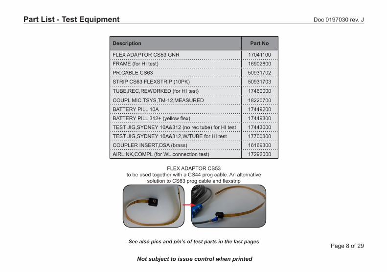
Description Part No
FLEX ADAPTOR CS53 GNR 17041100
FRAME (for HI test) 16902800
PR.CABLE CS63 50931702
STRIP CS63 FLEXSTRIP (10PK) 50931703
TUBE,REC,REWORKED (for HI test) 17460000
COUPL MIC,TSYS,TM-12,MEASURED 18220700
BATTERY PILL 10A 17449200
BATTERY PILL 312+ (yellow flex) 17449300
TEST JIG,SYDNEY 10A&312 (no rec tube) for HI test 17443000
TEST JIG,SYDNEY 10A&312,W/TUBE for HI test 17700300
COUPLER INSERT,DSA (brass) 16169300
AIRLINK,COMPL (for WL connection test) 17292000
FLEX ADAPTOR CS53to be used together with a CS44 prog cable. An alternative
solution to CS63 prog cable and flexstrip
Part List - Test Equipment
See also pics and p/n’s of test parts in the last pages
Doc 0197030 rev. J
Page 9 of 29
Not subject to issue control when printed
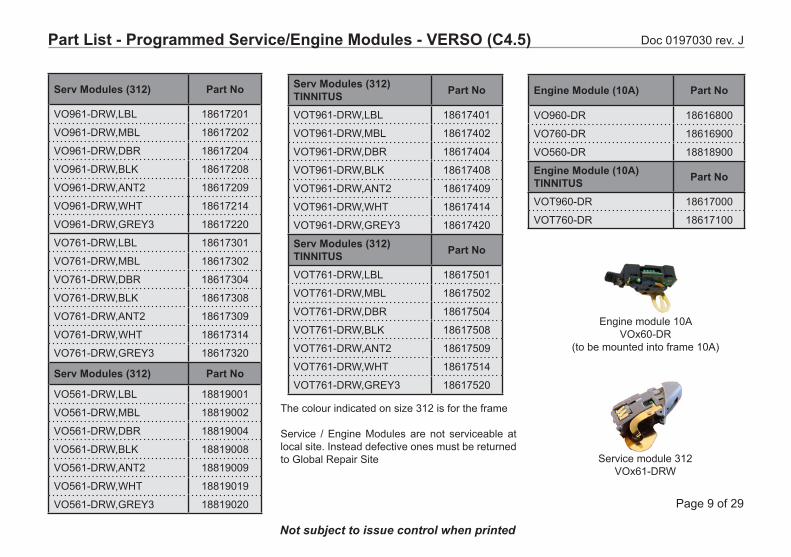
Part List - Programmed Service/Engine Modules - VERSO (C4.5)
The colour indicated on size 312 is for the frame
Service / Engine Modules are not serviceable at local site. Instead defective ones must be returned to Global Repair Site
Serv Modules (312) Part No
VO961-DRW,LBL 18617201
VO961-DRW,MBL 18617202
VO961-DRW,DBR 18617204
VO961-DRW,BLK 18617208
VO961-DRW,ANT2 18617209
VO961-DRW,WHT 18617214
VO961-DRW,GREY3 18617220
VO761-DRW,LBL 18617301
VO761-DRW,MBL 18617302
VO761-DRW,DBR 18617304
VO761-DRW,BLK 18617308
VO761-DRW,ANT2 18617309
VO761-DRW,WHT 18617314
VO761-DRW,GREY3 18617320
Serv Modules (312) Part No
VO561-DRW,LBL 18819001
VO561-DRW,MBL 18819002
VO561-DRW,DBR 18819004
VO561-DRW,BLK 18819008
VO561-DRW,ANT2 18819009
VO561-DRW,WHT 18819019
VO561-DRW,GREY3 18819020
Serv Modules (312)TINNITUS Part No
VOT961-DRW,LBL 18617401
VOT961-DRW,MBL 18617402
VOT961-DRW,DBR 18617404
VOT961-DRW,BLK 18617408
VOT961-DRW,ANT2 18617409
VOT961-DRW,WHT 18617414
VOT961-DRW,GREY3 18617420
Serv Modules (312)TINNITUS Part No
VOT761-DRW,LBL 18617501
VOT761-DRW,MBL 18617502
VOT761-DRW,DBR 18617504
VOT761-DRW,BLK 18617508
VOT761-DRW,ANT2 18617509
VOT761-DRW,WHT 18617514
VOT761-DRW,GREY3 18617520
Engine module 10A VOx60-DR
(to be mounted into frame 10A)
Engine Module (10A) Part No
VO960-DR 18616800
VO760-DR 18616900
VO560-DR 18818900
Engine Module (10A)TINNITUS Part No
VOT960-DR 18617000
VOT760-DR 18617100
Service module 312 VOx61-DRW
Doc 0197030 rev. J
Page 10 of 29
Not subject to issue control when printed
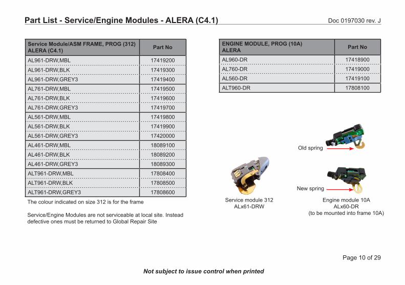
Part List - Service/Engine Modules - ALERA (C4.1)
Service Module/ASM FRAME, PROG (312)ALERA (C4.1) Part No
AL961-DRW,MBL 17419200
AL961-DRW,BLK 17419300
AL961-DRW,GREY3 17419400
AL761-DRW,MBL 17419500
AL761-DRW,BLK 17419600
AL761-DRW,GREY3 17419700
AL561-DRW,MBL 17419800
AL561-DRW,BLK 17419900
AL561-DRW,GREY3 17420000
AL461-DRW,MBL 18089100
AL461-DRW,BLK 18089200
AL461-DRW,GREY3 18089300
ALT961-DRW,MBL 17808400
ALT961-DRW,BLK 17808500
ALT961-DRW,GREY3 17808600Service module 312
ALx61-DRW
ENGINE MODULE, PROG (10A) ALERA Part No
AL960-DR 17418900
AL760-DR 17419000
AL560-DR 17419100
ALT960-DR 17808100
Engine module 10A ALx60-DR
(to be mounted into frame 10A)
Old spring
New spring
The colour indicated on size 312 is for the frame
Service/Engine Modules are not serviceable at local site. Instead defective ones must be returned to Global Repair Site

Doc 0197030 rev. J
Page 11 of 29
Not subject to issue control when printed
ColourVOx60-DR (Size 10A)
FRAME HSG L * HSG R * BAT DOOR MIC BAR
LBL 18085401 18092101 18092301 18085901 18085501
MBL 18085402 18092132 18092332 18085902 18085502
DBR 18085404 18092134 18092334 18085904 18085504
MON RED N/A 18092106 18092306 N/A N/A
BLK 18085408 N/A N/A 18085908 18085508
ANT2 18085409 18092109 18092309 18085909 18085509
MET N/A 18092110 18092310 N/A N/A
PRL WHT N/A 18092114 18092314 N/A N/A
OCN BLU N/A 18092118 18092318 N/A N/A
WHT 18085419 N/A N/A 18085919 18085519
GREY3 18085420 18092130 18092330 18085920 18085520
BLK GLOSS N/A 18092125 18092325 N/A N/A
All HSG parts are nano coated. Please also see “Colour Overview” page for colour of each HSG part
Part List - HSG Parts - VERSO Size 10A
* Printed “ReSound”
Doc 0197030 rev. J
Page 12 of 29
Not subject to issue control when printed
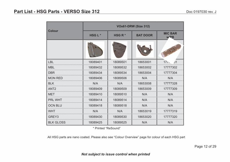
ColourVOx61-DRW (Size 312)
HSG L * HSG R * BAT DOOR MIC BARw/PB
LBL 18089401 18089501 18653001 17777301
MBL 18089432 18089532 18653002 17777302
DBR 18089434 18089534 18653004 17777304
MON RED 18089406 18089506 N/A N/A
BLK N/A N/A 18653008 17777328
ANT2 18089409 18089509 18653009 17777309
MET 18089410 18089510 N/A N/A
PRL WHT 18089414 18089514 N/A N/A
OCN BLU 18089418 18089518 N/A N/A
WHT N/A N/A 18653019 17777319
GREY3 18089430 18089530 18653020 17777320
BLK GLOSS 18089425 18089525 N/A N/A
All HSG parts are nano coated. Please also see “Colour Overview” page for colour of each HSG part
Part List - HSG Parts - VERSO Size 312
* Printed “ReSound”
Doc 0197030 rev. J
Page 13 of 29
Not subject to issue control when printed
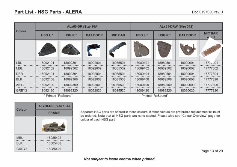
ColourALx60-DR (Size 10A) ALx61-DRW (Size 312)
HSG L * HSG R * BAT DOOR MIC BAR HSG L * HSG R * BAT DOOR MIC BARw/PB
LBL 18092101 18092301 18092001 18085501 18089401 18089501 18090001 17777301
MBL 18092102 18092302 18092002 18085502 18089402 18089502 18090002 17777302
DBR 18092104 18092304 18092004 18085504 18089404 18089504 18090004 17777304
BLK 18092108 18092308 18092008 18085508 18089408 18089508 18090008 17777328
ANT2 18092109 18092309 18092009 18085509 18089409 18089509 18090009 17777309
GREY3 18092120 18092320 18092020 18085520 18089420 18089520 18090020 17777320
Separate HSG parts are offered in these colours. If other colours are prefered a replacement kit must be ordered. Note that all HSG parts are nano coated. Please also see “Colour Overview” page for colour of each HSG part
Part List - HSG Parts - ALERA
ColourALx60-DR (Size 10A)
FRAME
MBL 18085402
BLK 18085408
GREY3 18085420
* Printed “ReSound” * Printed “ReSound”
Doc 0197030 rev. J
Page 14 of 29
Not subject to issue control when printed
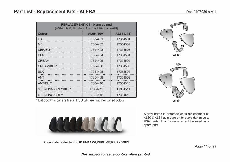
REPLACEMENT KIT - Nano coated(HSG L & R, Bat door, Mic bar / Mic bar w/PB)
Colour AL60 (10A) AL61 (312)LBL 17354401 17354501
MBL 17354402 17354502
DBR/BLK* 17354403 17354503
DBR 17354404 17354504
CREAM 17354405 17354505
CREAM/BLK* 17354406 17354506
BLK 17354408 17354508
ANT 17354409 17354509
ANT/BLK* 17354410 17354510
STERLING GREY/BLK* 17354411 17354511
STERLING GREY 17354412 17354512
* Bat door/mic bar are black. HSG L/R are first mentioned colour
Part List - Replacement Kits - ALERA
AL61
AL60
Please also refer to doc 0198410 WI,REPL KIT,RS SYDNEY
A grey frame is enclosed each replacement kit AL60 & AL61 as a support to avoid damages to HSG parts. This frame must not be used as a spare part
Doc 0197030 rev. J
Page 15 of 29
Not subject to issue control when printed
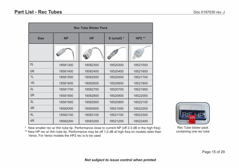
Part List - Rec Tubes
Rec Tube Blister Pack
Size NP HP S (small) * HP2 **
0L 18581300 18582300 18520300 18521500
0R 18581400 18582400 18520400 18521600
1L 18581500 18582500 18520500 18521700
1R 18581600 18582600 18520600 18521800
2L 18581700 18582700 18520700 18521900
2R 18581800 18582800 18520800 18522000
3L 18581900 18582900 18520900 18522100
3R 18582000 18583000 18521000 18522200
4L 18582100 18583100 18521100 18522300
4R 18582200 18583200 18521200 18522400
Rec Tube blister pack containing one rec tube
** New smaller rec w/ thin tube tip. Performance close to current NP (off 2-3 dB in the high freq)** New HP rec w/ thin tube tip. Performance may be off 1-2 dB at high freq on models older than ***Verso. For Verso models the HP2 rec is to be used

Doc 0197030 rev. J
Page 16 of 29
Not subject to issue control when printed
Part List - Domes for NP & HP Receiver
DOMES USED WITH NP REC
Description Bag (10 pcs)
Blister Pack (8 pcs)
DOME,REC,SZ5,SM 18501200 18607800
DOME,REC,SZ7,MDM 18501300 18607900
DOME,REC,SZ10,LGE 18501400 18608000
DOME,REC,EXT,SZ5,SM * 18501500 18608100
DOME,REC,EXT,SZ7,MDM * 18501600 18608200
DOME,REC,EXT,SZ10,LG * 18501700 18608300
DOME,REC,TULIP,STD 18501800 18608400
Dome EXT
Power DomesSizes S,M,L
Dome STD Tulip
DomesSizes S,M,L
* EXT: Extended length (longer tube)
Slide the dome down over the rec until the red (R) / blue (L) mark on rec is completely covered
DOMES USED WITH HP REC
Description Bag (10 pcs)
Blister Pack (8 pcs)
DOME,REC,PWR,SM 18501900 18608500
DOME,REC,PWR,MDM 18502000 18608600
DOME,REC,PWR,LGE 18502100 18608700
Dome EXTSizes S,M,L
Normal Power dome compatible
High Power dome compatible
R HR R
R
H
Doc 0197030 rev. J
Page 17 of 29
Not subject to issue control when printed
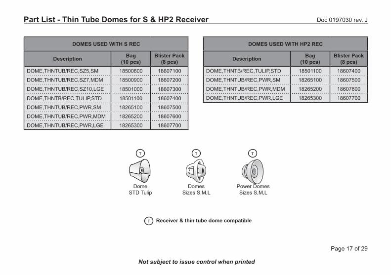
Part List - Thin Tube Domes for S & HP2 Receiver
DOMES USED WITH S REC
Description Bag (10 pcs)
Blister Pack (8 pcs)
DOME,THNTUB/REC,SZ5,SM 18500800 18607100
DOME,THNTUB/REC,SZ7,MDM 18500900 18607200
DOME,THNTUB/REC,SZ10,LGE 18501000 18607300
DOME,THNTB/REC,TULIP,STD 18501100 18607400
DOME,THNTUB/REC,PWR,SM 18265100 18607500
DOME,THNTUB/REC,PWR,MDM 18265200 18607600
DOME,THNTUB/REC,PWR,LGE 18265300 18607700
Power DomesSizes S,M,L
Dome STD Tulip
DomesSizes S,M,L
DOMES USED WITH HP2 REC
Description Bag (10 pcs)
Blister Pack (8 pcs)
DOME,THNTB/REC,TULIP,STD 18501100 18607400
DOME,THNTUB/REC,PWR,SM 18265100 18607500
DOME,THNTUB/REC,PWR,MDM 18265200 18607600
DOME,THNTUB/REC,PWR,LGE 18265300 18607700
T T T
Receiver & thin tube dome compatibleT
Doc 0197030 rev. J
Page 18 of 29
Not subject to issue control when printed
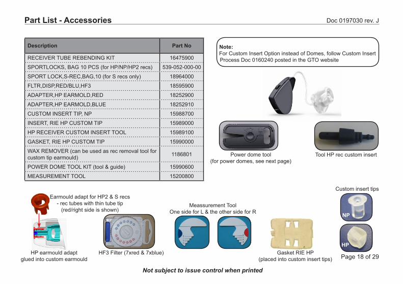
Note: For Custom Insert Option instead of Domes, follow Custom Insert *Process Doc 0160240 posted in the GTO website
Description Part No
RECEIVER TUBE REBENDING KIT 16475900
SPORTLOCKS, BAG 10 PCS (for HP/NP/HP2 recs) 539-052-000-00
SPORT LOCK,S-REC,BAG,10 (for S recs only) 18964000
FLTR,DISP,RED/BLU,HF3 18595900
ADAPTER,HP EARMOLD,RED 18252900
ADAPTER,HP EARMOLD,BLUE 18252910
CUSTOM INSERT TIP, NP 15988700
INSERT, RIE HP CUSTOM TIP 15989000
HP RECEIVER CUSTOM INSERT TOOL 15989100
GASKET, RIE HP CUSTOM TIP 15990000
WAX REMOVER (can be used as rec removal tool for custom tip earmould) 1186801
POWER DOME TOOL KIT (tool & guide) 15990600
MEASUREMENT TOOL 15200800
Power dome tool (for power domes, see next page)
Tool HP rec custom insert
Part List - Accessories
Meassurement ToolOne side for L & the other side for R
Custom insert tips
NP
HF3 Filter (7xred & 7xblue) Gasket RIE HP (placed into custom insert tips)
Earmould adapt for HP2 & S recs - rec tubes with thin tube tip
(red/right side is shown)
HPHP earmould adapt
glued into custom earmould

Doc 0197030 rev. J
Page 19 of 29
Not subject to issue control when printed
Power dome tool
As the HP rec is pushed into the power dome, carefull pull out the power dome tool
Place the longer length of the rectangular cavity of the power dome over the power dome tool.
Ensure that the power dome is installed on the power dome tool by check-ing it and it is flushed even with the tool as shown (3rd pic)
Squeeze and hold bottom of the power dome tool to open the power dome rectangular cavity.Insert the HP rec, with the longer length of the rec parallel to the longer length of the rectangular cavity of the power dome
Prepare a HF3 tool with HF3
Insert HF3 tool with HF3 all the way in the power dome until it passes through the rectangular cavity of the power dome
Power Dome Tool
Doc 0197030 rev. J
Page 20 of 29
Not subject to issue control when printed
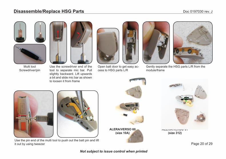
Multi toolScrewdriver/pin
Disassemble/Replace HSG Parts
Use the screwdriver end of the tool to separate mic bar. Pull slightly backward. Lift upwards a bit and slide mic bar as shown to loosen it from frame
Open batt door to get easy ac-cess to HSG parts L/R
Gently separate the HSG parts L/R from the module/frame
Use the pin end of the multi tool to push out the batt pin and lift it out by using tweezer
ALERA/VERSO 60(size 10A)
ALERA/VERSO 61(size 312)
Doc 0197030 rev. J
Page 21 of 29
Not subject to issue control when printed
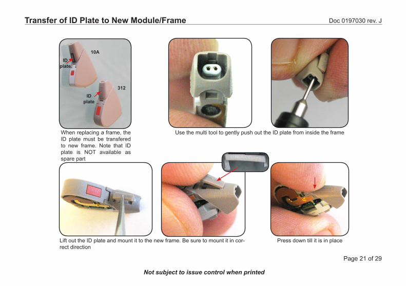
When replacing a frame, the ID plate must be transfered to new frame. Note that ID plate is NOT available as spare part
ID plate
ID plate
Use the multi tool to gently push out the ID plate from inside the frame
Lift out the ID plate and mount it to the new frame. Be sure to mount it in cor-rect direction
Press down till it is in place
10A
312
Transfer of ID Plate to New Module/Frame

Doc 0197030 rev. J
Page 22 of 29
Not subject to issue control when printed
After separating HSG parts from frame, push out the engine module from the frame
Engine module 10A
Frame 10A
Slide the new engine module into the frame and press it down until it is correct in place. Check that mic filters are not damaged. Mount the HSG parts. Transfer the ID plate if a new frame is used
Replace Engine Module 10A
New springOld spring
Doc 0197030 rev. J
Page 23 of 29
Not subject to issue control when printed
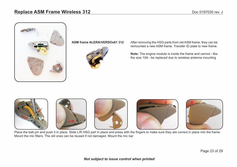
ASM frame ALERA/VERSOx61 312 After removing the HSG parts from old ASM frame, they can be remounted a new ASM frame. Transfer ID plate to new frame.
Note: The engine module is inside the frame and cannot - like the size 10A - be replaced due to wireless antenna mounting
Place the batt pin and push it in place. Slide L/R HSG part in place and press with the fingers to make sure they are correct in place into the frame. Mount the mic filters. The old ones can be reused if not damaged. Mount the mic bar
Replace ASM Frame Wireless 312
Doc 0197030 rev. J
Page 24 of 29
Not subject to issue control when printed
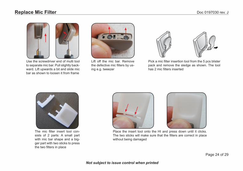
Lift off the mic bar. Remove the defective mic filters by us-ing e.g. tweezer
The mic filter insert tool con-sists of 2 parts: A small part with mic bar shape and a big-ger part with two sticks to press the two filters in place
Place the insert tool onto the HI and press down until it clicks. The two sticks will make sure that the filters are correct in place without being damaged
Use the screwdriver end of multi tool to separate mic bar. Pull slightly back-ward. Lift upwards a bit and slide mic bar as shown to loosen it from frame
Pick a mic filter insertion tool from the 5 pcs blister pack and remove the sledge as shown. The tool has 2 mic filters inserted
Replace Mic Filter
Doc 0197030 rev. J
Page 25 of 29
Not subject to issue control when printed
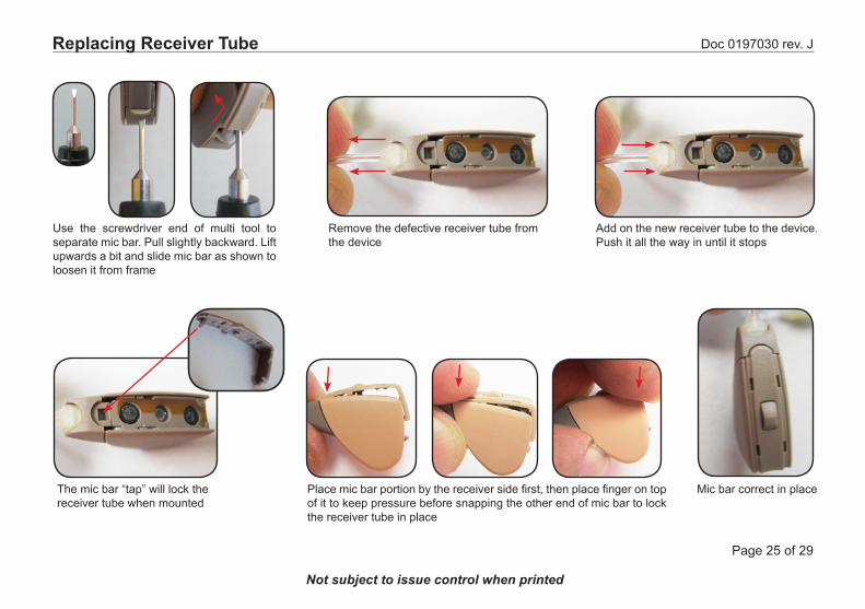
Replacing Receiver Tube
Use the screwdriver end of multi tool to separate mic bar. Pull slightly backward. Lift upwards a bit and slide mic bar as shown to loosen it from frame
Remove the defective receiver tube from the device
Mic bar correct in place
Add on the new receiver tube to the device. Push it all the way in until it stops
Place mic bar portion by the receiver side first, then place finger on top of it to keep pressure before snapping the other end of mic bar to lock the receiver tube in place
The mic bar “tap” will lock the receiver tube when mounted
Doc 0197030 rev. J
Page 26 of 29
Not subject to issue control when printed
Service Procedure & Postponement
Service Procedure:
- Save user settings with Device Diagnostics or Aventa - Disassemble faulty device- Replace module with a new service module from stock- Assemble device- Restore user settings with Device Diagnostics or Aventa- Load customer serial No (ID Plate) using Device Diagnostics or DSA6000
Postponement Procedure:
- Disassemble device- Replace parts with replacement kit from stock- Transfer ID-plate from old housing to new housing- Verify battery door by open and close once
Doc 0197030 rev. J
Page 27 of 29
Not subject to issue control when printed
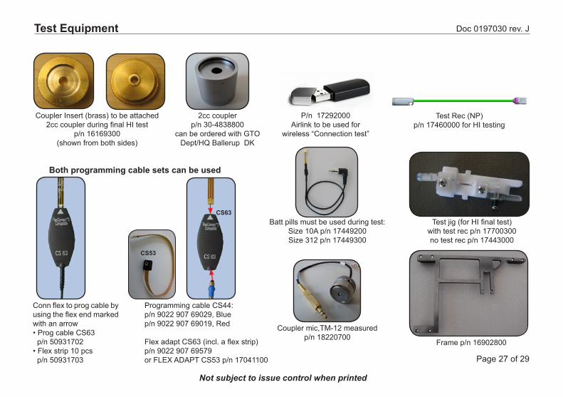
Test Equipment
Coupler Insert (brass) to be attached 2cc coupler during final HI test
p/n 16169300(shown from both sides)
Batt pills must be used during test:Size 10A p/n 17449200 Size 312 p/n 17449300
Frame p/n 16902800
Test jig (for HI final test)with test rec p/n 17700300no test rec p/n 17443000
2cc couplerp/n 30-4838800
can be ordered with GTO Dept/HQ Ballerup DK
Test Rec (NP) p/n 17460000 for HI testing
P/n 17292000Airlink to be used for
wireless “Connection test”
Conn flex to prog cable by using the flex end marked with an arrow• Prog cable CS63 op/n 50931702• Flex strip 10 pcsop/n 50931703
Both programming cable sets can be used
Programming cable CS44:p/n 9022 907 69029, Bluep/n 9022 907 69019, Red
Flex adapt CS63 (incl. a flex strip)p/n 9022 907 69579or FLEX ADAPT CS53 p/n 17041100
CS53
CS63
Coupler mic,TM-12 measuredp/n 18220700
Doc 0197030 rev. J
Page 28 of 29
Not subject to issue control when printed
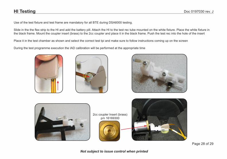
Use of the test fixture and test frame are mandatory for all BTE during DSA6000 testing.
Slide in the the flex strip to the HI and add the battery pill. Attach the HI to the test rec tube mounted on the white fixture. Place the white fixture in the black frame. Mount the coupler insert (brass) to the 2cc coupler and place it in the black frame. Push the test rec into the hole of the insert
Place it in the test chamber as shown and select the correct test tpi and make sure to follow instructions coming up on the screen
During the test programme execution the IAD calibration will be performed at the appropriate time
HI Testing
2cc coupler Insert (brass) p/n 16169300
Doc 0197030 rev. J
Page 29 of 29
Not subject to issue control when printed
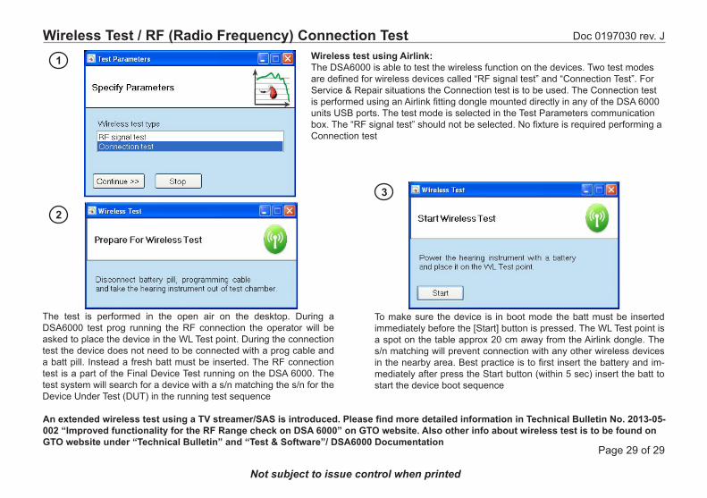
Wireless Test / RF (Radio Frequency) Connection Test
The test is performed in the open air on the desktop. During a DSA6000 test prog running the RF connection the operator will be asked to place the device in the WL Test point. During the connection test the device does not need to be connected with a prog cable and a batt pill. Instead a fresh batt must be inserted. The RF connection test is a part of the Final Device Test running on the DSA 6000. The test system will search for a device with a s/n matching the s/n for the Device Under Test (DUT) in the running test sequence
To make sure the device is in boot mode the batt must be inserted immediately before the [Start] button is pressed. The WL Test point is a spot on the table approx 20 cm away from the Airlink dongle. The s/n matching will prevent connection with any other wireless devices in the nearby area. Best practice is to first insert the battery and im-mediately after press the Start button (within 5 sec) insert the batt to start the device boot sequence
1
2
3
Wireless test using Airlink:The DSA6000 is able to test the wireless function on the devices. Two test modes are defined for wireless devices called “RF signal test” and “Connection Test”. For Service & Repair situations the Connection test is to be used. The Connection test is performed using an Airlink fitting dongle mounted directly in any of the DSA 6000 units USB ports. The test mode is selected in the Test Parameters communication box. The “RF signal test” should not be selected. No fixture is required performing a Connection test
An extended wireless test using a TV streamer/SAS is introduced. Please find more detailed information in Technical Bulletin No. 2013-05-002 “Improved functionality for the RF Range check on DSA 6000” on GTO website. Also other info about wireless test is to be found on GTO website under “Technical Bulletin” and “Test & Software”/ DSA6000 Documentation