Embed Size (px)
Citation preview
Technical Note - TN 083: 2016
Technical Note - TN 083: 2016
Subject: Withdrawal of legacy RailCorp signalling set to work manuals
Issued date: 22 December 2016
Effective date: 22 December 2016
For queries regarding this document [email protected]
www.asa.transport.nsw.gov.au
This technical note is issued by the Asset Standards Authority (ASA) to notify that the following
legacy RailCorp signalling set to work manuals have been withdrawn:
• TMG 1350 DC Track Circuits – Set Up, Test and Certification, version 1.1
• TMG 1351 AC Immune DC Track Circuits – Set Up, Test and Certification, version 1.1
• TMG 1352 Jeumont-Schneider Impulse Track Circuits – Set Up and Adjustment Procedure,
version 1.2
• TMG 1353 AC Single Rail Track Circuits – Set Up, Test and Certification, version 1.1
• TMG 1354 AC Double Rail Track Circuits – Set Up, Test and Certification, version 1.1
• TMG 1355 CSEE UM71 AF Jointless Track Circuits – Set Up, Test and Certification,
version 1.1
• TMG 1356 WBS FS2500 AF Jointless Track Circuits – Set Up, Test and Certification,
version 1.1
• TMG 1357 ML TI21 AF Jointless Track Circuits - Set Up, Test and Certification, version 1.1
Note: All enquiries regarding the technical content of the manuals listed in this technical note
should be directed to [email protected].
© State of NSW through Transport for NSW Page 1 of 2
Technical Note - TN 083: 2016
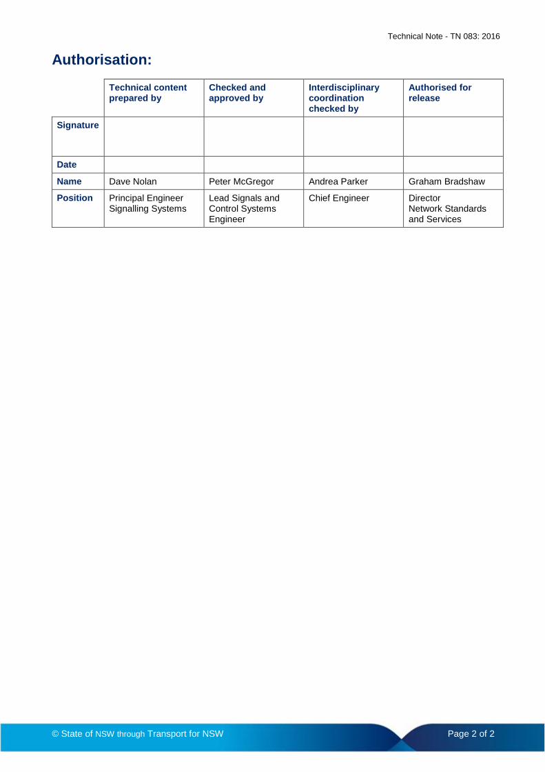
Authorisation:
Technical content prepared by
Checked and approved by
Interdisciplinary coordination checked by
Authorised for release
Signature
Date
Name Dave Nolan Peter McGregor Andrea Parker Graham Bradshaw
Position Principal Engineer Signalling Systems
Lead Signals and Control Systems Engineer
Chief Engineer Director Network Standards and Services
© State of NSW through Transport for NSW Page 2 of 2
With
draw
n - f
or re
fere
nce
only
Engi
neer
ing
Man
ual
ML T121 AF JOINTLESS TRACK CIRCUITS – SET UP, TEST AND
CERTIFICATION
TMG 1357
Engineering Manual Signals Set to Work Manual
Version 1.1
Issued March 2013
Owner: Warwick Allison, Chief Engineer Signals and Control Systems
Approved by:
Warwick Allison Chief Engineer Signals and Control Systems
Authorised by:
Paul Szacsvay Principal Engineer Signal Technology
Disclaimer This document was prepared for use on the RailCorp Network only. RailCorp makes no warranties, express or implied, that compliance with the contents of this document shall be sufficient to ensure safe systems or work or operation. It is the document user’s sole responsibility to ensure that the copy of the document it is viewing is the current version of the document as in use by RailCorp. RailCorp accepts no liability whatsoever in relation to the use of this document by any party, and RailCorp excludes any liability which arises in any manner by the use of this document. Copyright The information in this document is protected by Copyright and no part of this document may be reproduced, altered, stored or transmitted by any person without the prior consent of RailCorp.
UNCONTROLLED WHEN PRINTED Page 1 of 16
RailCorp Engineering Manual — Signals Set to Work Manual ML T121 AF Jointless Track Circuits – Set Up, Test and Certification TMG 1357
© RailCorp Page 2 of 16 Issued March 2013 UNCONTROLLED WHEN PRINTED Version 1.1
With
draw
n - f
or re
fere
nce
only
Document control
Version Date Summary of change
1.0 21/08/2007 Replaced SC 07 44 03 00 WI - ML TI21 AF Jointless Track Circuits – Set-Up, Test and Certification – v2.0 of 1 November 2001. New RailCorp format
1.1 March 2013 Application of TMA 400 format
Summary of changes from previous version
Summary of change Section
RailCorp Engineering Manual — Signals Set to Work Manual ML T121 AF Jointless Track Circuits – Set Up, Test and Certification TMG 1357
© RailCorp Page 3 of 16 Issued March 2013 UNCONTROLLED WHEN PRINTED Version 1.1
Contents
1 Introduction .............................................................................................................................4 2 Set to Work ..............................................................................................................................4 2.1 Equipment for Set-to-Work........................................................................................................4 2.2 Staffing for Set-to-Work.............................................................................................................4 2.3 Clear Old Track Connections....................................................................................................5 2.4 Make New Connections ............................................................................................................5 2.5 Bonding .....................................................................................................................................5 2.6 Rail Connections Check............................................................................................................5 2.7 Check Auxiliary Track Equipment .............................................................................................5 2.8 Equipment Check......................................................................................................................5 2.9 Terminations .............................................................................................................................5 2.10 Power-Up ..................................................................................................................................6 2.11 Check Rail Connections............................................................................................................6 2.12 Shunt and Correspondence Check...........................................................................................6 2.13 Documentation Check...............................................................................................................6 2.14 Notification to Control................................................................................................................6 3 Final Adjustment .....................................................................................................................6 3.1 Equipment for Test and Certification.........................................................................................6 3.2 Staffing for Test and Certification..............................................................................................7 3.3 Resonated Impedance Bonds...................................................................................................7 3.4 Initial Receiver Adjustment........................................................................................................7 3.5 Drop-Shunt Check and Final Gain Adjustment .........................................................................7 3.6 Intermediate Receiver ...............................................................................................................8 3.7 Standard Values Check ............................................................................................................8 4 Certification .............................................................................................................................8 4.1 Zero-Feed Receiver Input .........................................................................................................8 4.2 Test Shunt.................................................................................................................................8 4.3 Communicating Results ............................................................................................................9 4.4 History Cards ............................................................................................................................9 4.5 Final Documentation .................................................................................................................9 5 Sign Off and Leave Site..........................................................................................................9 Appendix A Intermediate Receiver (IRx) Adjustment .............................................................10 Adjustment Sequence ............................................................................................................................10 IRx Amplifier Adjustment ........................................................................................................................10 Initial IRx adjustment ..............................................................................................................................10 Final IRx Adjustment ..............................................................................................................................10 Appendix B Technical Notes .....................................................................................................11 Appendix C Operating Principles and Hardware.....................................................................12 Description of ML TI21 Track Circuit ......................................................................................................12 Basic Operation ......................................................................................................................................12 Equipment ..............................................................................................................................................13
Transmitter ..............................................................................................................................13 Tuning Unit ..............................................................................................................................14 Track Tuning Unit....................................................................................................................14 Receiver .................................................................................................................................14 Power Supply Unit...................................................................................................................15
Track Circuit Sensitivity Adjustment .......................................................................................................15
With
draw
n - f
or re
fere
nce
only
RailCorp Engineering Manual — Signals Set to Work Manual ML T121 AF Jointless Track Circuits – Set Up, Test and Certification TMG 1357
© RailCorp Page 4 of 16 Issued March 2013 UNCONTROLLED WHEN PRINTED Version 1.1
1 Introduction This procedure describes the activities involved in commissioning and certifying MT TI21 audio-frequency jointless track circuits, in a typical RailCorp installation.
Commissioning a new track circuit consists of removing any old equipment, connecting the new equipment and any new bonding, powering-up the new equipment, then carrying out the final adjustments and certification checks.
Before proceeding with testing and commissioning, persons not familiar with the operation of ML Audio Frequency Track Circuits are advised to read Appendix C, which gives a concise description of the equipment operating principles and hardware.
The commissioning procedure is described in two stages. Firstly, there are the set-to-work activities, by which the new track circuit is made operational. This is followed by the test and certification phase, when finally adjustments and checks are carried out to ensure that the track circuit is operating correctly and safely. When there are only a few track circuits to be commissioned, the duties can be carried out by a combined team. All care must be taken then, that none of the necessary checks and tests specified in this document are omitted.
2 Set to Work This section describes the activities generally carried out by the set-to-work team. It covers removal of any old track circuit equipment and the connection and powering-up of the new equipment.
2.1 Equipment for Set-to-Work The following is the minimum equipment required by the set-to-work team:
• Cable cutter, to remove old rail connections • Bond punches, 3-stage punch, hammer • Spanners:
– 17 mm ring or deep socket (rail connections) – 17 mm tube (Tuning unit connections) – 12 mm socket (TU mounting bolts)
• 2BA tube, insulated, for TU and capacitor connections. • Pliers, long-nose insulated, for adjusting capacitors • Multimeter (high-impedance, true-RMS, with frequency response to 3 kHz or
better. (Fluke 8026, 87, or equivalent). Used for AC and DC measurements. • Switchable shunt box, with 0.15 ohm setting, complete with track clips. • ML TI21 track circuit manual • Track circuit Set-to-Work master sheet, clipboard and pens.
2.2 Staffing for Set-to-Work The normal staff requirement is two competent electricians or equivalent, plus one assistant/lookout. Where bonding and track connections are not 100% prepared, then a bonder and mate with full equipment should be available.
The allocation of set-to-work teams for the commissioning will depend on the level of readiness on commissioning day. Where all connections and bonding are in place, ready for final connection, the allocation should be made on the basis of 3/4 hour per track circuit, for complete set-to-work by a two-man team.
With
draw
n - f
or re
fere
nce
only
RailCorp Engineering Manual — Signals Set to Work Manual ML T121 AF Jointless Track Circuits – Set Up, Test and Certification TMG 1357
© RailCorp Page 5 of 16 Issued March 2013 UNCONTROLLED WHEN PRINTED Version 1.1
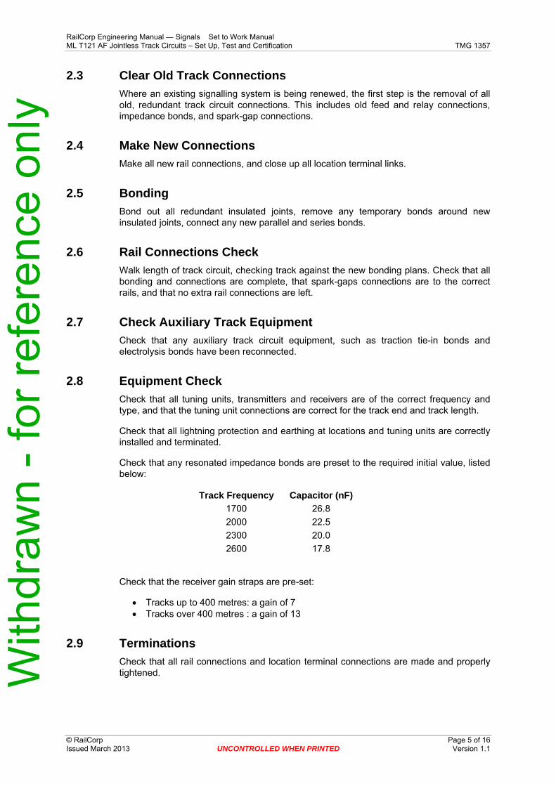
2.3 Clear Old Track Connections Where an existing signalling system is being renewed, the first step is the removal of all old, redundant track circuit connections. This includes old feed and relay connections, impedance bonds, and spark-gap connections.
2.4 Make New Connections Make all new rail connections, and close up all location terminal links.
2.5 Bonding Bond out all redundant insulated joints, remove any temporary bonds around new insulated joints, connect any new parallel and series bonds.
2.6 Rail Connections Check Walk length of track circuit, checking track against the new bonding plans. Check that all bonding and connections are complete, that spark-gaps connections are to the correct rails, and that no extra rail connections are left.
2.7 Check Auxiliary Track Equipment Check that any auxiliary track circuit equipment, such as traction tie-in bonds and electrolysis bonds have been reconnected.
2.8 Equipment Check Check that all tuning units, transmitters and receivers are of the correct frequency and type, and that the tuning unit connections are correct for the track end and track length.
Check that all lightning protection and earthing at locations and tuning units are correctly installed and terminated.
Check that any resonated impedance bonds are preset to the required initial value, listed below:
Track Frequency 1700
Capacitor (nF) 26.8
2000 22.5 2300 20.0 2600 17.8
Check that the receiver gain straps are pre-set:
• Tracks up to 400 metres: a gain of 7 • Tracks over 400 metres : a gain of 13
2.9 Terminations Check that all rail connections and location terminal connections are made and properly tightened. With
draw
n - f
or re
fere
nce
only
RailCorp Engineering Manual — Signals Set to Work Manual ML T121 AF Jointless Track Circuits – Set Up, Test and Certification TMG 1357
© RailCorp Page 6 of 16 Issued March 2013 UNCONTROLLED WHEN PRINTED Version 1.1
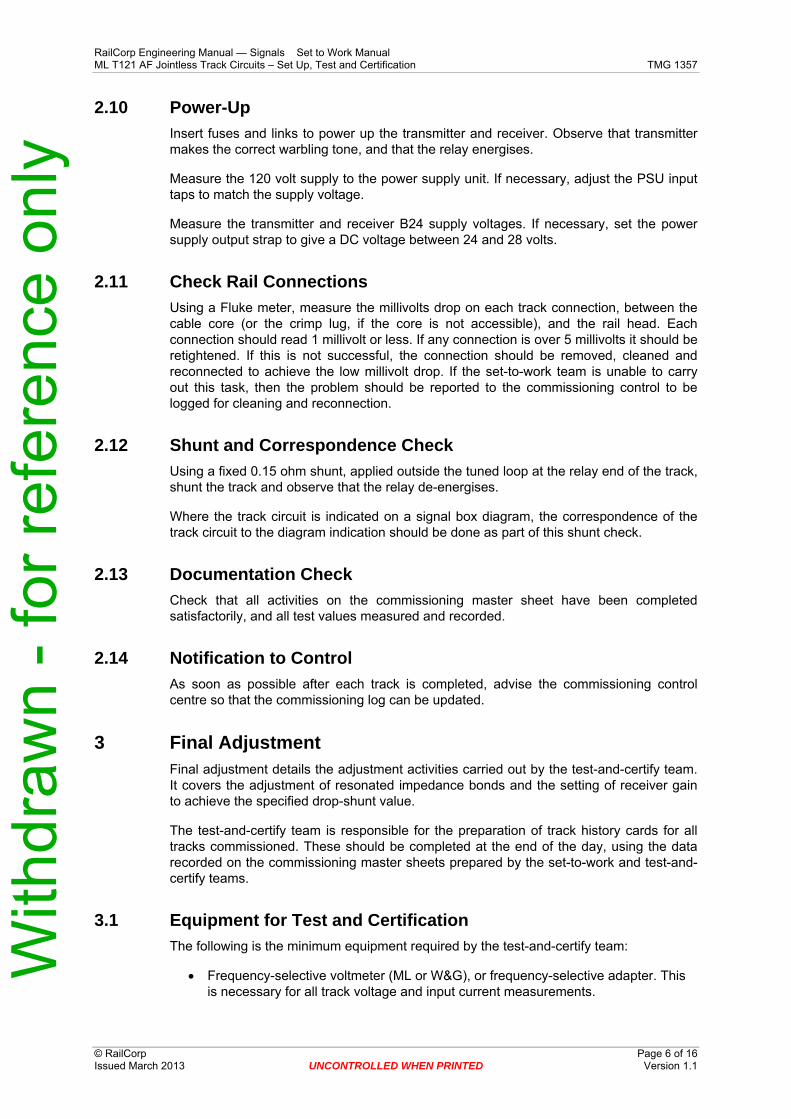
2.10 Power-Up Insert fuses and links to power up the transmitter and receiver. Observe that transmitter makes the correct warbling tone, and that the relay energises.
Measure the 120 volt supply to the power supply unit. If necessary, adjust the PSU input taps to match the supply voltage.
Measure the transmitter and receiver B24 supply voltages. If necessary, set the power supply output strap to give a DC voltage between 24 and 28 volts.
2.11 Check Rail Connections Using a Fluke meter, measure the millivolts drop on each track connection, between the cable core (or the crimp lug, if the core is not accessible), and the rail head. Each connection should read 1 millivolt or less. If any connection is over 5 millivolts it should be retightened. If this is not successful, the connection should be removed, cleaned and reconnected to achieve the low millivolt drop. If the set-to-work team is unable to carry out this task, then the problem should be reported to the commissioning control to be logged for cleaning and reconnection.
2.12 Shunt and Correspondence Check Using a fixed 0.15 ohm shunt, applied outside the tuned loop at the relay end of the track, shunt the track and observe that the relay de-energises.
Where the track circuit is indicated on a signal box diagram, the correspondence of the track circuit to the diagram indication should be done as part of this shunt check.
2.13 Documentation Check Check that all activities on the commissioning master sheet have been completed satisfactorily, and all test values measured and recorded.
2.14 Notification to Control As soon as possible after each track is completed, advise the commissioning control centre so that the commissioning log can be updated.
3 Final Adjustment Final adjustment details the adjustment activities carried out by the test-and-certify team. It covers the adjustment of resonated impedance bonds and the setting of receiver gain to achieve the specified drop-shunt value.
The test-and-certify team is responsible for the preparation of track history cards for all tracks commissioned. These should be completed at the end of the day, using the data recorded on the commissioning master sheets prepared by the set-to-work and test-and-certify teams.
3.1 Equipment for Test and Certification The following is the minimum equipment required by the test-and-certify team:
• Frequency-selective voltmeter (ML or W&G), or frequency-selective adapter. This is necessary for all track voltage and input current measurements.
With
draw
n - f
or re
fere
nce
only
RailCorp Engineering Manual — Signals Set to Work Manual ML T121 AF Jointless Track Circuits – Set Up, Test and Certification TMG 1357
© RailCorp Page 7 of 16 Issued March 2013 UNCONTROLLED WHEN PRINTED Version 1.1
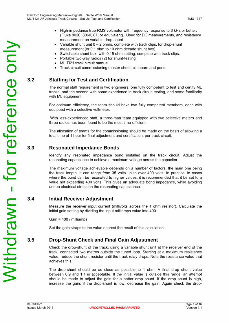
• High-impedance true-RMS voltmeter with frequency response to 3 kHz or better. (Fluke 8026, 8060, 87, or equivalent). Used for DC measurements, and resistance measurement on variable drop-shunt
• Variable shunt unit 0 – 2 ohms, complete with track clips, for drop-shunt measurement (or 0.1 ohm to 10 ohm decade shunt box)
• Switchable shunt box, with 0.15 ohm setting, complete with track clips. • Portable two-way radios (2) for shunt-testing. • ML TI21 track circuit manual • Track circuit commissioning master sheet, clipboard and pens.
3.2 Staffing for Test and Certification The normal staff requirement is two engineers, one fully competent to test and certify ML tracks, and the second with some experience in track circuit testing, and some familiarity with ML equipment.
For optimum efficiency, the team should have two fully competent members, each with equipped with a selective voltmeter.
With less-experienced staff, a three-man team equipped with two selective meters and three radios has been found to be the most time-efficient.
The allocation of teams for the commissioning should be made on the basis of allowing a total time of 1 hour for final adjustment and certification, per track circuit.
3.3 Resonated Impedance Bonds Identify any resonated impedance bond installed on the track circuit. Adjust the resonating capacitance to achieve a maximum voltage across the capacitor.
The maximum voltage achievable depends on a number of factors, the main one being the track length. It can range from 35 volts up to over 400 volts. In practice, in cases where the bond can be resonated to higher values, it is recommended that it be set to a value not exceeding 400 volts. This gives an adequate bond impedance, while avoiding undue electrical stress on the resonating capacitance.
3.4 Initial Receiver Adjustment Measure the receiver input current (millivolts across the 1 ohm resistor). Calculate the initial gain setting by dividing the input milliamps value into 400.
Gain = 400 / milliamps
Set the gain straps to the value nearest the result of this calculation.
3.5 Drop-Shunt Check and Final Gain Adjustment Check the drop-shunt of the track, using a variable shunt unit at the receiver end of the track, connected two metres outside the tuned loop. Starting at a maximum resistance value, reduce the shunt resistor until the track relay drops. Note the resistance value that achieves this.
The drop-shunt should be as close as possible to 1 ohm. A final drop shunt value between 0.9 and 1.1 is acceptable. If the initial value is outside this range, an attempt should be made to adjust the gain for a better drop shunt. If the drop shunt is high, increase the gain; if the drop-shunt is low, decrease the gain. Again check the drop-With
draw
n - f
or re
fere
nce
only
RailCorp Engineering Manual — Signals Set to Work Manual ML T121 AF Jointless Track Circuits – Set Up, Test and Certification TMG 1357
© RailCorp Page 8 of 16 Issued March 2013 UNCONTROLLED WHEN PRINTED Version 1.1
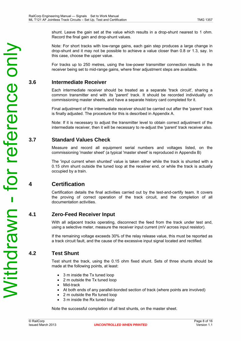
shunt. Leave the gain set at the value which results in a drop-shunt nearest to 1 ohm. Record the final gain and drop-shunt values.
Note: For short tracks with low-range gains, each gain step produces a large change in drop-shunt and it may not be possible to achieve a value closer than 0.8 or 1.3, say. In this case, choose the upper value.
For tracks up to 250 metres, using the low-power transmitter connection results in the receiver being set to mid-range gains, where finer adjustment steps are available.
3.6 Intermediate Receiver Each intermediate receiver should be treated as a separate 'track circuit', sharing a common transmitter end with its 'parent' track. It should be recorded individually on commissioning master sheets, and have a separate history card completed for it.
Final adjustment of the intermediate receiver should be carried out after the 'parent' track is finally adjusted. The procedure for this is described in Appendix A.
Note: If it is necessary to adjust the transmitter level to obtain correct adjustment of the intermediate receiver, then it will be necessary to re-adjust the 'parent' track receiver also.
3.7 Standard Values Check Measure and record all equipment serial numbers and voltages listed, on the commissioning 'master sheet' (a typical 'master sheet' is reproduced in Appendix B)
The 'input current when shunted' value is taken either while the track is shunted with a 0.15 ohm shunt outside the tuned loop at the receiver end, or while the track is actually occupied by a train.
4 Certification Certification details the final activities carried out by the test-and-certify team. It covers the proving of correct operation of the track circuit, and the completion of all documentation activities.
4.1 Zero-Feed Receiver Input With all adjacent tracks operating, disconnect the feed from the track under test and, using a selective meter, measure the receiver input current (mV across input resistor).
If the remaining voltage exceeds 30% of the relay release value, this must be reported as a track circuit fault, and the cause of the excessive input signal located and rectified.
4.2 Test Shunt Test shunt the track, using the 0.15 ohm fixed shunt. Sets of three shunts should be made at the following points, at least:
• 3 m inside the Tx tuned loop • 2 m outside the Tx tuned loop • Mid-track • At both ends of any parallel-bonded section of track (where points are involved) • 2 m outside the Rx tuned loop • 3 m inside the Rx tuned loop
Note the successful completion of all test shunts, on the master sheet.
With
draw
n - f
or re
fere
nce
only
RailCorp Engineering Manual — Signals Set to Work Manual ML T121 AF Jointless Track Circuits – Set Up, Test and Certification TMG 1357
© RailCorp Page 9 of 16 Issued March 2013 UNCONTROLLED WHEN PRINTED Version 1.1
4.3 Communicating Results As soon as possible after each track is completed, advise the commissioning control centre so that the log can be updated.
If any problem is found with the track, notify the Commissioning Control centre as soon as possible. If the problem does not interfere with completion of track testing, record it in the 'remarks' section of the 'master sheet', and continue. If the problem does preclude immediate completion of testing, notify Control and then proceed to the next track and return when corrections have been carried out.
4.4 History Cards When all track work is complete, use the details recorded on the 'master sheets' to fill in individual history cards for all tracks tested by the team. The cards should be signed by the responsible RailCorp member of the team.
4.5 Final Documentation Where separate documentation is provided for the recording of commissioning activities, ensure that the track testing records are completed and signed for all tracks tested by the team.
Ensure that all defects or problems encountered are recorded in the commissioning log.
Ensure that the numbers of all tracks completed, and of all tracks allocated to the team but not completed by the team, for whatever reason, are recorded either in the test records or the commissioning log.
Ensure that the handing-over of completed commissioning master sheets and track history cards is recorded in the commissioning log.
5 Sign Off and Leave Site
End of Procedure
With
draw
n - f
or re
fere
nce
only
RailCorp Engineering Manual — Signals Set to Work Manual ML T121 AF Jointless Track Circuits – Set Up, Test and Certification TMG 1357
© RailCorp Page 10 of 16 Issued March 2013 UNCONTROLLED WHEN PRINTED Version 1.1
Appendix A Intermediate Receiver (IRx) Adjustment
Adjustment Sequence The final adjustment of the intermediate receiver should be carried out after the 'parent' track is finally adjusted.
Note: If it is necessary to adjust the transmitter level to obtain correct adjustment of the intermediate receiver, then it will be necessary to re-adjust the 'parent' track receiver also.
IRx Amplifier Adjustment Measure the receiver input current from the intermediate receiver selective amplifier. If necessary, adjust the amplifier attenuator, until the receiver input current is between 30 mA and 50 mA. This adjustment is made by strapping on the left-hand row of terminals on the IRx amplifier. Connect the strap from the 'Com' terminal, to one of the terminals marked from '1' to '7'.
Note the receiver input current (millivolts across the 1 ohm resistor).
Initial IRx adjustment Calculate the initial receiver gain setting by dividing the input milliamps value into 400.
Gain = 400 / milliamps
Set the receiver gain straps to the value nearest the result of this calculation.
Final IRx Adjustment Measure the IRx drop shunt value at a point 1 metre on the transmitter side of the IRx pickup unit. Adjust the receiver sensitivity to obtain a drop shunt value between 0.8 and 1.0 ohms.
With
draw
n - f
or re
fere
nce
only
RailCorp Engineering Manual — Signals Set to Work Manual ML T121 AF Jointless Track Circuits – Set Up, Test and Certification TMG 1357
© RailCorp Page 11 of 16 Issued March 2013 UNCONTROLLED WHEN PRINTED Version 1.1
Appendix B Technical Notes Note 1 Resonated Impedance Bonds (WB&S 2000R/AF)
Initial capacitor settings
This table gives initial values to which a WB&S 2000R/AF resonated impedance bond should be preset to ensure operation of the track circuit when initially powered-up. The final resonation of the bond should be done as part of the final adjustment of the track circuit.
Track Frequency 1700
Capacitor (nF) 26.8
2000 22.5 2300 20.0 2600 17.8
Where the total length of the track circuit is less than 450 metres, experience has shown that the beast approach is to leave the bond unresonated and simply open-circuit all terminals in the capacitor box.
Note 2 Transmitter Modulation Check
It is a feature of the operation of the ML TI21 track circuit that the transmitter's frequency modulation makes the output frequency alternate between two frequencies 10Hz above and below the nominal frequency, about 5 times per second. Because a frequency counter functions by counting cycles over a set counting period, a frequency measurement on a normally functioning TI21 track will return a reading equal to the average output frequency - the nominal value.
If the modulation fails, the receiver output will drop to zero even though all operating voltages on the track measure completely normal. There are two possible ways to check whether modulation is present:
• Possible only at the transmitter end:
Listen to the transmitter. A properly functioning transmitter emits a 'warbling' tone; a failed unit emits a steady tone, or none at all.
This check is not absolutely effective, as it may be difficult to hear the warbling in some circumstances.
• At any point on the entire track circuit: Measure the track circuit frequency. (The Fluke 8060 or 87 multimeter is ideal for this test.)
If the frequency measured equals the nominal frequency +/− 2 Hz, then the transmitter modulation is operating normally; failed modulation is indicated by a reading about 10 Hz above or below the nominal.
– e.g. for a 1700 Hz track (centre frequency 1699 Hz), – 1697 to 1702 means transmitter OK, and – 1685 or 1715 means no modulation present.
If modulation is not working, then the transmitter is faulty. With
draw
n - f
or re
fere
nce
only
RailCorp Engineering Manual — Signals Set to Work Manual ML T121 AF Jointless Track Circuits – Set Up, Test and Certification TMG 1357
© RailCorp Page 12 of 16 Issued March 2013 UNCONTROLLED WHEN PRINTED Version 1.1
Appendix C Operating Principles and Hardware
Description of ML TI21 Track Circuit The ML Audio Frequency Track Circuit equipment is used both in jointless track circuits and in insulated joint tracks by installing Impedance Bonds.
The track circuit employs four base frequencies, (A) = 1699 Hz, (B) =2296 Hz, (C) =1996 Hz and (D) =2593 Hz. These frequencies are modulated by +/ 17 Hz to minimise the possibility of false operation due to the presence of traction harmonics or other extraneous voltages close to the base frequencies. Both the base and the modulating frequency must be present for the track circuit to operate. To ensure maximum frequency separation for correct function of the tuned separation joint, track circuits with base frequencies of (A) 1699 Hz and (B) 2296 Hz are generally allocated to the `DOWN’ track, and (C) 1996 Hz and (D) 2593 Hz to the `UP' track.
Units with the above four frequencies are the preferred types. There are four more types of units available with non-preferred frequencies.
Where one or more jointed track circuits are installed between two ML track circuits the track frequencies should still be alternated. This prevents the possibility of false operation of the adjacent receiver in the event of a block joint failure.
The length of an ML track circuit is measured from the centre of the tuned loop to the centre of the next tuned loop or from one impedance bond to the next impedance bond. The maximum length of an end fed circuit is 900 metres. This maximum length only applies when there is no additional loading on the track circuit such as impedance bonds, electrolysis bonds, bad ballast conditions, or extended cabling to the transmitter tuning unit. The minimum length of track circuit is 50 metres.
Basic Operation The jointless track circuit consists of an audio frequency transmitter and a receiver operating at the same frequency whose output is fed to a signalling relay (track relay). Connection to the track is by means of a Tuning unit of same frequency which also provides impedance matching and DC isolation. Adjacent tracks are separated either by insulated joints or by tuned loops consisting of the tuning units of the adjacent tracks.
Transmitters and receivers require 24V DC supply for their operation.
The tuned loop consists of a pair of tuning units of approximately 600 Hz separation and a specific length of track.
The tuning unit of a particular track having one frequency offers high impedance whereas it presents low impedance to the adjacent track having different frequency.
The high impedance presented on the tuning unit makes an optimum point for the connection of a transmitter or a receiver. At the other end of the tuned loop, the rail to rail voltage of this track is shunted by the low impedance presented at its frequency by the tuning unit of the adjacent track circuit, leaving only a small amount of signal to appear on the adjacent track transmitter or receiver. Thus the action of the tuned loop limits the propagation of the track circuit voltage past the adjacent track circuit tuning unit, simulating an insulated joint of tracks.
The overlap zone of the tuned track circuit is measured from the point midway between the two track tuning units. Within this region both track circuits may be de-energised by a shunt. The specified shunt value will de-energise both track circuits at the mid point and
With
draw
n - f
or re
fere
nce
only
RailCorp Engineering Manual — Signals Set to Work Manual ML T121 AF Jointless Track Circuits – Set Up, Test and Certification TMG 1357
© RailCorp Page 13 of 16 Issued March 2013 UNCONTROLLED WHEN PRINTED Version 1.1
the shunt value decreases to zero at a distance of 5 metres further away from the tuned circuit associated with the frequency concerned. The length of the overlap zone depends on ballast conditions but will always be between 2 metres and 10 metres.
The end termination unit is a self contained tuned circuit for applications where the track circuit isolation using the electrical separation joint is not required. Such applications are end feed or end receive adjacent to insulated rail joints and for centre feed arrangements. The end termination unit employs the same housing as the standard tuning unit and also the same terminations.
The transmitter output is approximately 10 to 16 Volts depending upon the frequency. The tuning unit feeds 0.8 Volts to 1.8 Volts AC to the track. A voltage drop of approximately 2 Volts occurs in the leads from the transmitter to the tuning unit.
Along the track the voltage decreases to a value of between 0.5 Volts to 1 Volt AC at the low power mode and between 0.5 Volts to 1.6 Volts at the normal power mode at the tuning unit on the receiver end, depending on the track length, ballast conditions and the frequency. At the receiver end the voltage is applied to a tuning unit which feeds the track voltage to the receiver. If the voltage is of sufficient magnitude and of correct frequency and modulation the track relay is energised by the receiver.
The transmitter output and the receiver input provide a low impedance load to the track circuit which is necessary for the correct tuning of the tuned area.
At the tuning unit, receivers are always connected to terminals 1 and 2. For normal power mode (track circuit lengths of 200 to 900 metres) the transmitters are connected to terminals 4 and 5, whilst at low power mode (track circuits of 50 to 250 metres long) the transmitters are connected to terminals 1 and 2.
The electrical separation of adjacent track circuits is accomplished by tuning the inductance of 20 metres of track, using two track tuning units.
No facilities are provided on the transmitter for adjustments. The receiver input signal will vary with track length, ballast condition, and traction bonding arrangements.
Whenever measuring voltage levels on ML track circuit equipment (with the exception of transmitter output voltages), it is important that a frequency selective voltmeter be used. (Fluke meter is not frequency selective).
If such a meter is not available, then the transmitter of any adjacent ML or any Audio Frequency track circuit should be disabled by opening the outgoing terminals while the measurements are being taken. Failure to follow this rule could result in misleading readings.
Equipment
Transmitter 24 volt DC supply is connected to B24 and N24. The average consumption is maximum 2.2 amperes when a train is shunting the transmitter end of the track circuit. The transmitter output voltage is in the order of 10 volts for frequencies A and C and approximately 15 volts for frequencies B and D. The base frequencies are modulated as follows:
• A: 1699 Hz with +/−17 Hz modulation. • B: 2296 Hz with +/−17 Hz modulation. • C: 1996 Hz with +/−17 Hz modulation. • D: 2593 Hz with +/−17 Hz modulation.
With
draw
n - f
or re
fere
nce
only
RailCorp Engineering Manual — Signals Set to Work Manual ML T121 AF Jointless Track Circuits – Set Up, Test and Certification TMG 1357
© RailCorp Page 14 of 16 Issued March 2013 UNCONTROLLED WHEN PRINTED Version 1.1
The above four frequencies are keyed (modulated) at a rate of 5 Hz.
The output powers:
• Normal Power Mode: 40 watts to track (max). • Low Power Mode: 3 watts to track (max).
The loop resistance of the connecting cable to the tuning unit is 0.5 ohms maximum for a track of length 900 metres. This can be relaxed for a short track circuit, or if a matching transformer (MTU) is used.
There is no adjustment to be done at the transmitter.
Tuning Unit Transmitters and receivers are always connected through tuning units to impedance bonds or the track.
The tuning unit performs three different functions:
• To match the impedance of the track to the characteristic impedance of the connecting cables and the equipment connected to the other end of the cables.
• Different connection facilities for receiver and transmitter connections, and for low power and normal power operation of the transmitter.
• Tuned to the frequency of the track, it offers high impedance to its own track frequency and low impedance to the frequency of the adjacent track.
Track Tuning Unit Therefore there are four different `preferred' type of tuning units for four different `preferred' track frequencies.
There is no difference between the receiver and the transmitter tuning units. Only the cables are connected to different terminals as shown in the drawing above.
Tuning units consist of capacitors and inductor which act as resonant filters and a transformer for transformation of voltage and matching of impedance. The contents of all tuning units are fully encapsulated and inaccessible except for the terminals.
The track connection is to the lugs T1 and T2. Receivers and transmitters are normally connected to the tuning unit terminals 1, 2, 4 and 5 as shown in the drawing.
When a track is terminated at an insulated joint (with or without an impedance bond) the tuning unit should be connected in parallel with an SI unit (air-cored inductor), or else a special End Tuning Unit should be used.
Receiver 24 volts D.C. supply is connected to B24 and N24. The maximum current consumption, when relay is energised, is 0.5 A.
The track voltage entering the receiver from the track side tuning unit is fed into a variable ratio transformer before being applied to the filter and detection circuits of the receiver.
The signal from the track tuning unit is fed into this transformer which has three input windings. These windings are so arranged that the variation of input connections gives a range of gain settings from 1 to 13 in steps of 1. The isolation transformer is screened to eliminate stray induced voltage in the secondary windings. The screen is connected to
With
draw
n - f
or re
fere
nce
only
RailCorp Engineering Manual — Signals Set to Work Manual ML T121 AF Jointless Track Circuits – Set Up, Test and Certification TMG 1357
© RailCorp Page 15 of 16 Issued March 2013 UNCONTROLLED WHEN PRINTED Version 1.1
the external earth terminal. The secondary winding of each input filter is tuned to select one signal coming from the associated transmitter.
The 1 ohm terminal resistor is wired in series with the transformer input for monitoring the input current without disconnecting the input signal. The voltage across the resistor is 1 mV/mA.
The gain setting of the receiver is done as per the following paragraph 4 "Track Circuit Sensitivity Adjustment".
The output of the receiver is 50 volts D.C. at 50 mA. The input cable loop resistance from the tuning unit is 7 ohms maximum.
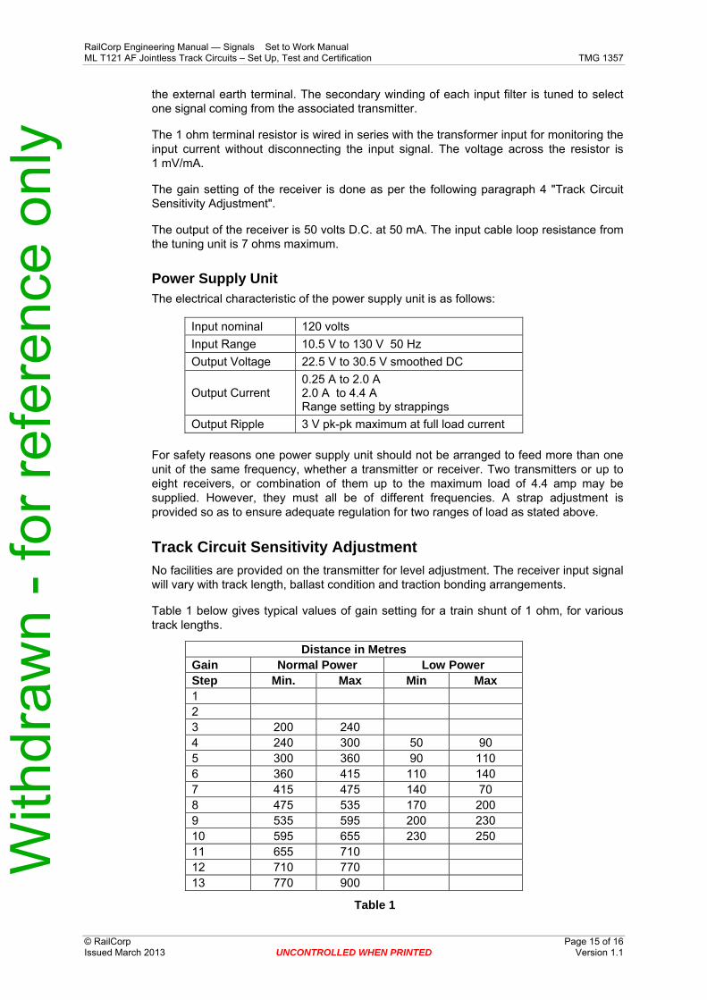
Power Supply Unit The electrical characteristic of the power supply unit is as follows:
Input nominal 120 volts Input Range 10.5 V to 130 V 50 Hz Output Voltage 22.5 V to 30.5 V smoothed DC
Output Current 0.25 A to 2.0 A 2.0 A to 4.4 A Range setting by strappings
Output Ripple 3 V pk-pk maximum at full load current For safety reasons one power supply unit should not be arranged to feed more than one unit of the same frequency, whether a transmitter or receiver. Two transmitters or up to eight receivers, or combination of them up to the maximum load of 4.4 amp may be supplied. However, they must all be of different frequencies. A strap adjustment is provided so as to ensure adequate regulation for two ranges of load as stated above.
Track Circuit Sensitivity Adjustment No facilities are provided on the transmitter for level adjustment. The receiver input signal will vary with track length, ballast condition and traction bonding arrangements.
Table 1 below gives typical values of gain setting for a train shunt of 1 ohm, for various track lengths.
Distance in Metres Gain Normal Power Low Power Step Min. Max Min Max 1 2 3 200 240 4 240 300 50 90 5 300 360 90 110 6 360 415 110 140 7 415 475 140 70 8 475 535 170 200 9 535 595 200 230 10 595 655 230 250 11 655 710 12 710 770 13 770 900
Table 1
With
draw
n - f
or re
fere
nce
only
RailCorp Engineering Manual — Signals Set to Work Manual ML T121 AF Jointless Track Circuits – Set Up, Test and Certification TMG 1357
© RailCorp Page 16 of 16 Issued March 2013 UNCONTROLLED WHEN PRINTED Version 1.1
Prior to commissioning, the receiver gain should be preset according to the length of the track, with the receiver gain straps pre-wired as follows:
• Tracks up to 400 metres: a gain of 7 • Tracks over 400 metres : a gain of 13
At commissioning, the track circuit should be tested for drop- shunt value by means of a variable shunt box connected across the rails adjacent to the rail connections of the track tuning unit which is feeding the receiver. This is the worst case point for the shunt value. Higher values will be attained at other points in the track circuit. For track circuits with the normal power connection the gain setting should be adjusted to give a shunt value of 0.8 ohms to 1.2 ohms.
For track circuits with low power connections (track length 50 metres to 250 metres), it is recommended that the gain setting should be adjusted to give a shunt value of 1.3 ohms to 1.7 ohms
With
draw
n - f
or re
fere
nce
only