Embed Size (px)
Citation preview
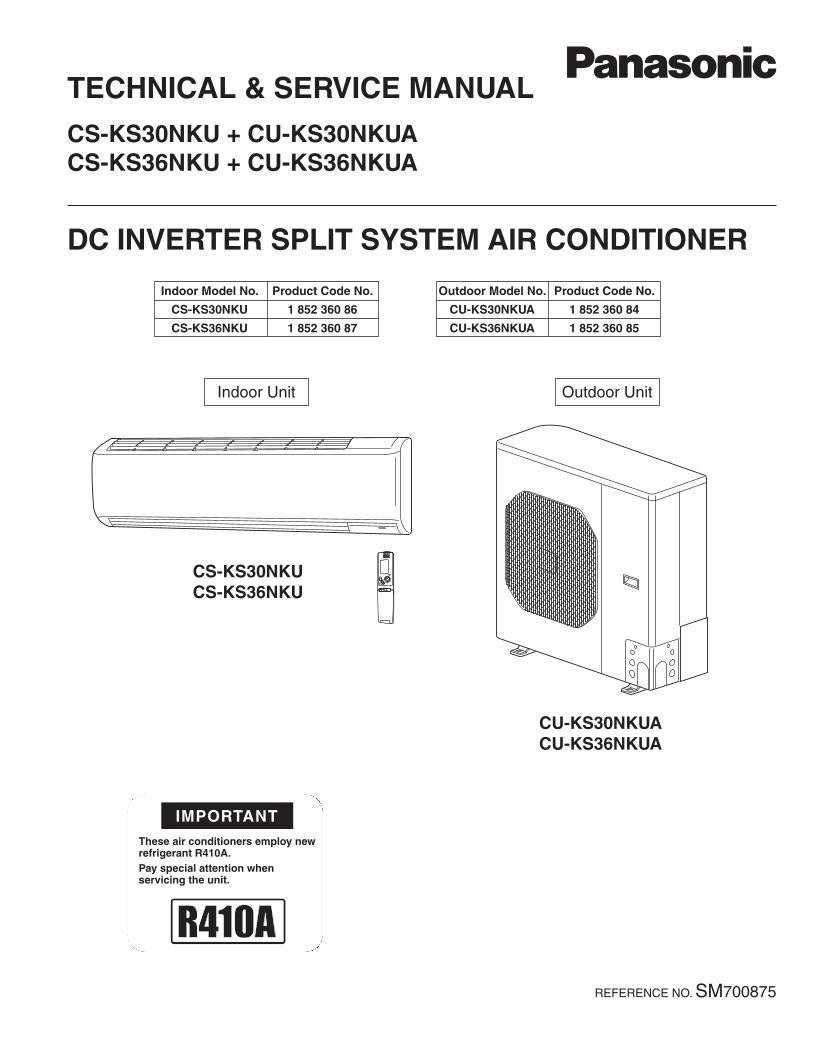
AIR CONDITIONER
IMPORTANTThese air conditioners employ newrefrigerant R410A.Pay special attention whenservicing the unit.
TECHNICAL & SERVICE MANUAL
CS-KS30NKU + CU-KS30NKUACS-KS36NKU + CU-KS36NKUA
DC INVERTER SPLIT SYSTEM AIR CONDITIONER
Outdoor Model No.
CU-KS30NKUA
CU-KS36NKUA
Product Code No.
1 852 360 84
1 852 360 85
Indoor Unit Outdoor Unit
CS-KS30NKUCS-KS36NKU
CU-KS30NKUACU-KS36NKUA
Indoor Model No.
CS-KS30NKU
CS-KS36NKU
Product Code No.
1 852 360 86
1 852 360 87
REFERENCE NO. SM700875
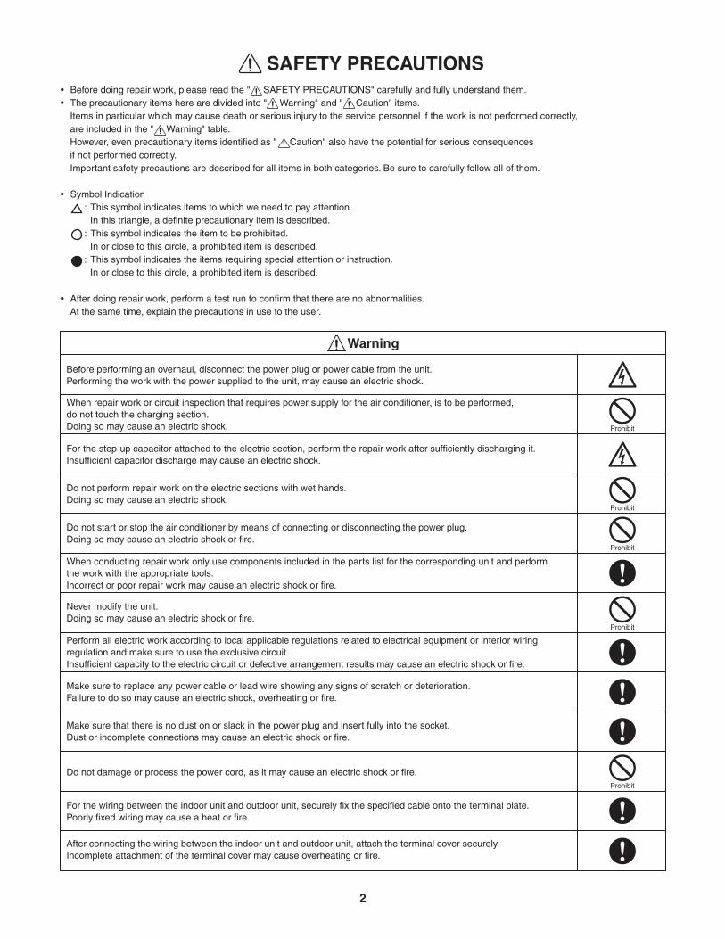
• Before doing repair work, please read the " SAFETY PRECAUTIONS" carefully and fully understand them. • The precautionary items here are divided into " Warning" and " Caution" items.
Items in particular which may cause death or serious injury to the service personnel if the work is not performed correctly, are included in the " Warning" table.However, even precautionary items identified as " Caution" also have the potential for serious consequencesif not performed correctly.Important safety precautions are described for all items in both categories. Be sure to carefully follow all of them.
• Symbol Indication: This symbol indicates items to which we need to pay attention.
In this triangle, a definite precautionary item is described.: This symbol indicates the item to be prohibited.
In or close to this circle, a prohibited item is described.: This symbol indicates the items requiring special attention or instruction.
In or close to this circle, a prohibited item is described.
• After doing repair work, perform a test run to confirm that there are no abnormalities.At the same time, explain the precautions in use to the user.
SAFETY PRECAUTIONS
Warning
Before performing an overhaul, disconnect the power plug or power cable from the unit.Performing the work with the power supplied to the unit, may cause an electric shock.
When repair work or circuit inspection that requires power supply for the air conditioner, is to be performed, do not touch the charging section. Doing so may cause an electric shock.
For the step-up capacitor attached to the electric section, perform the repair work after sufficiently discharging it.Insufficient capacitor discharge may cause an electric shock.
Do not perform repair work on the electric sections with wet hands. Doing so may cause an electric shock.
Do not start or stop the air conditioner by means of connecting or disconnecting the power plug. Doing so may cause an electric shock or fire.
When conducting repair work only use components included in the parts list for the corresponding unit and perform the work with the appropriate tools.Incorrect or poor repair work may cause an electric shock or fire.
Never modify the unit. Doing so may cause an electric shock or fire.
Perform all electric work according to local applicable regulations related to electrical equipment or interior wiring regulation and make sure to use the exclusive circuit.Insufficient capacity to the electric circuit or defective arrangement results may cause an electric shock or fire.
Make sure to replace any power cable or lead wire showing any signs of scratch or deterioration. Failure to do so may cause an electric shock, overheating or fire.
Make sure that there is no dust on or slack in the power plug and insert fully into the socket. Dust or incomplete connections may cause an electric shock or fire.
Do not damage or process the power cord, as it may cause an electric shock or fire.
For the wiring between the indoor unit and outdoor unit, securely fix the specified cable onto the terminal plate.Poorly fixed wiring may cause a heat or fire.
After connecting the wiring between the indoor unit and outdoor unit, attach the terminal cover securely. Incomplete attachment of the terminal cover may cause overheating or fire.
Prohibit
Prohibit
Prohibit
Prohibit
Prohibit
2
Warning
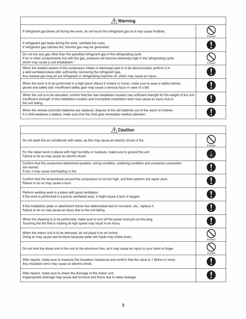
If refrigerant gas blows off during the work, do not touch the refrigerant gas as it may cause frostbite.
If refrigerant gas leaks during the work, ventilate the room.If refrigerant gas catches fire, harmful gas may be generated.
Do not mix any gas other than the specified refrigerant gas in the refrigerating cycle. If air or other contaminants mix with the gas, pressure will become extremely high in the refrigerating cycle, which may cause a unit breakdown."
When the welded section of the compressor intake or discharge pipe is to be disconnected, perform it in a well-ventilated place after sufficiently recovering the refrigerant gas.Any residue gas may jet out refrigerant or refrigerating machine oil, which may cause an injury.
When the work is to be performed in a high place (About 2 meters or more), make sure to wear a safety helmet, gloves and safety belt. Insufficient safety gear may cause a serious injury in case of a fall.
When the unit is to be relocated, confirm that the new installation location has sufficient strength for the weight of the unit.Insufficient strength of the installation location and incomplete installation work may cause an injury due to the unit falling.
When the remote controller batteries are replaced, dispose of the old batteries out of the reach of children. If a child swallows a battery, make sure that the child gets immediate medical attention.
Caution
Do not wash the air conditioner with water, as this may cause an electric shock or fire.
For the repair work in places with high humidity or moisture, make sure to ground the unit. Failure to do so may cause an electric shock.
Confirm that the component attachment position, wiring condition, soldering condition and connector connection are normal. If not, it may cause overheating or fire.
Confirm that the temperature around the compressor is not too high, and then perform the repair work. Failure to do so may cause a burn.
Perform welding work in a place with good ventilation. If the work is performed in a poorly ventilated area, it might cause a lack of oxygen.
If the installation plate or attachment frame has deteriorated due to corrosion, etc., replace it.Failure to do so may cause an injury due to the unit falling.
When the cleaning is to be performed, make sure to turn off the power and pull out the plug. Touching the fan that is rotating at high speed may result in an injury.
When the indoor unit is to be removed, do not place it on an incline. Doing so may cause wet furniture because water left inside may trickle down.
Do not hold the sharp end of the unit or the aluminum fins, as it may cause an injury to your hand or finger.
After repairs, make sure to measure the insulation resistance and confirm that the value is 1 Mohm or more. Any insulation error may cause an electric shock.
After repairs, make sure to check the drainage of the indoor unit. Inappropriate drainage may cause wet furniture and floors due to water leakage.
Prohibit
Prohibit
Prohibit
Prohibit
Prohibit
3
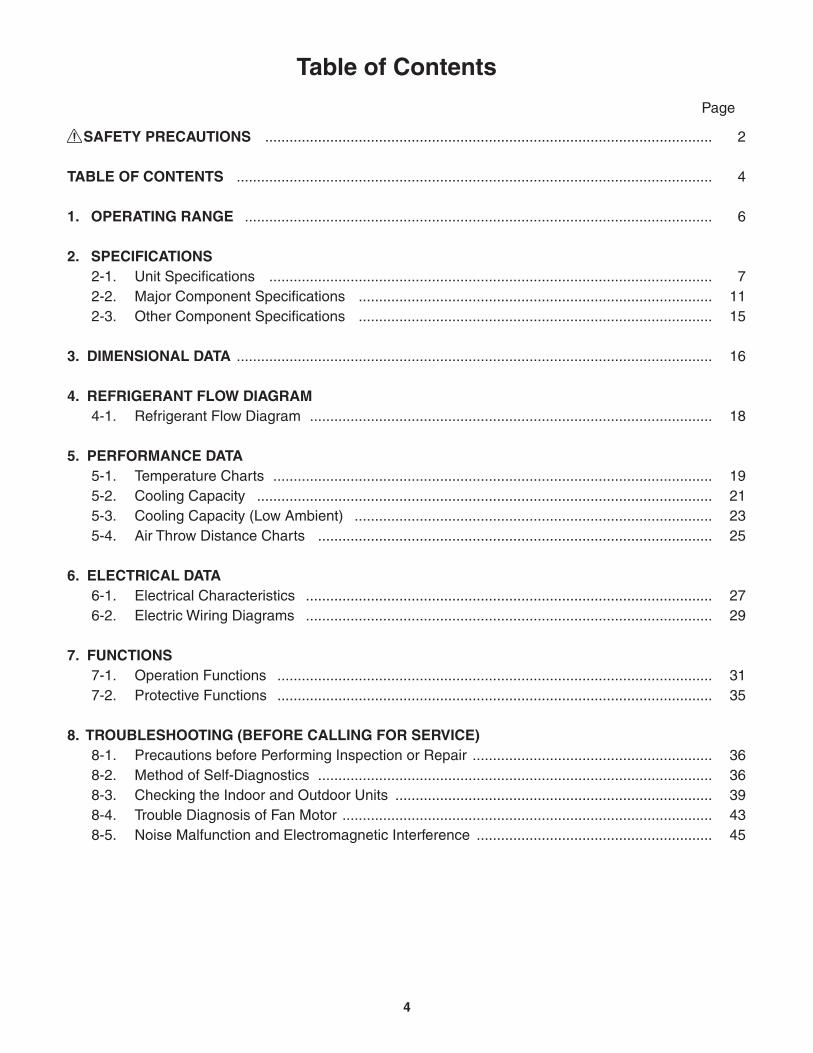
Table of Contents
SAFETY PRECAUTIONS
TABLE OF CONTENTS
1. OPERATING RANGE
2. SPECIFICATIONS2-1. Unit Specifications 2-2. Major Component Specifications 2-3. Other Component Specifications
3. DIMENSIONAL DATA
4. REFRIGERANT FLOW DIAGRAM4-1. Refrigerant Flow Diagram
5. PERFORMANCE DATA5-1. Temperature Charts5-2. Cooling Capacity5-3. Cooling Capacity (Low Ambient)5-4. Air Throw Distance Charts
6. ELECTRICAL DATA6-1. Electrical Characteristics6-2. Electric Wiring Diagrams
7. FUNCTIONS7-1. Operation Functions7-2. Protective Functions
8. TROUBLESHOOTING (BEFORE CALLING FOR SERVICE)8-1. Precautions before Performing Inspection or Repair8-2. Method of Self-Diagnostics8-3. Checking the Indoor and Outdoor Units8-4. Trouble Diagnosis of Fan Motor8-5. Noise Malfunction and Electromagnetic Interference
2
4
6
71115
16
18
19212325
2729
3135
3636394345
..............................................................................................................
.....................................................................................................................
...................................................................................................................
...........................................................................................................................................................................................................................................................................................
.....................................................................................................................
...................................................................................................
............................................................................................................................................................................................................................
.........................................................................................................................................................................................
....................................................................................................
....................................................................................................
...........................................................................................................
...........................................................................................................
............................................................................................................................................................
.........................................................................................................................................................................
..........................................................
Page
4
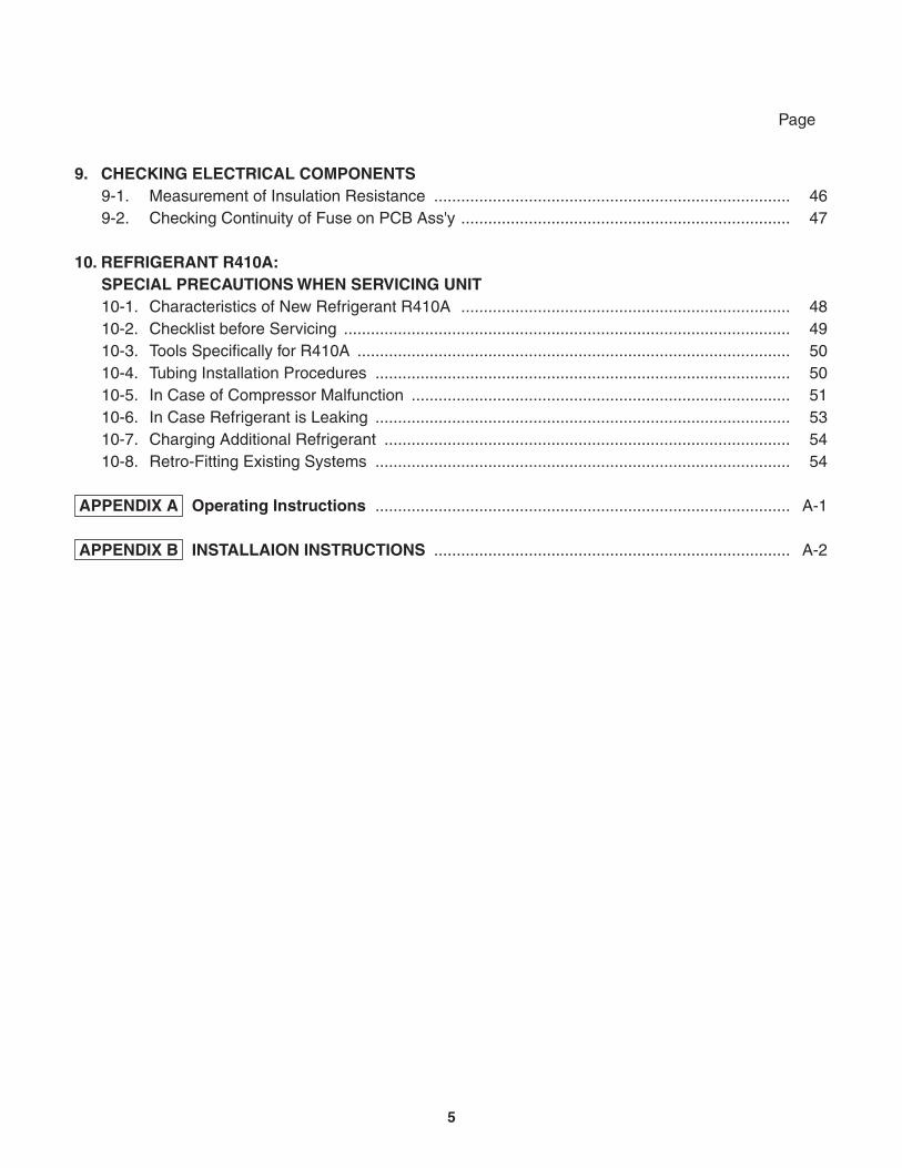
9. CHECKING ELECTRICAL COMPONENTS9-1. Measurement of Insulation Resistance9-2. Checking Continuity of Fuse on PCB Ass'y
10. REFRIGERANT R410A: SPECIAL PRECAUTIONS WHEN SERVICING UNIT10-1. Characteristics of New Refrigerant R410A10-2. Checklist before Servicing10-3. Tools Specifically for R410A10-4. Tubing Installation Procedures10-5. In Case of Compressor Malfunction10-6. In Case Refrigerant is Leaking10-7. Charging Additional Refrigerant10-8. Retro-Fitting Existing Systems
APPENDIX A Operating Instructions
APPENDIX B INSTALLAION INSTRUCTIONS
4647
4849505051535454
A-1
A-2
........................................................................................................................................................
............................................................................................................................................................................
............................................................................................................................................................................................
................................................................................................................................................................................
......................................................................................................................................................................................
............................................................................................
...............................................................................
Page
5
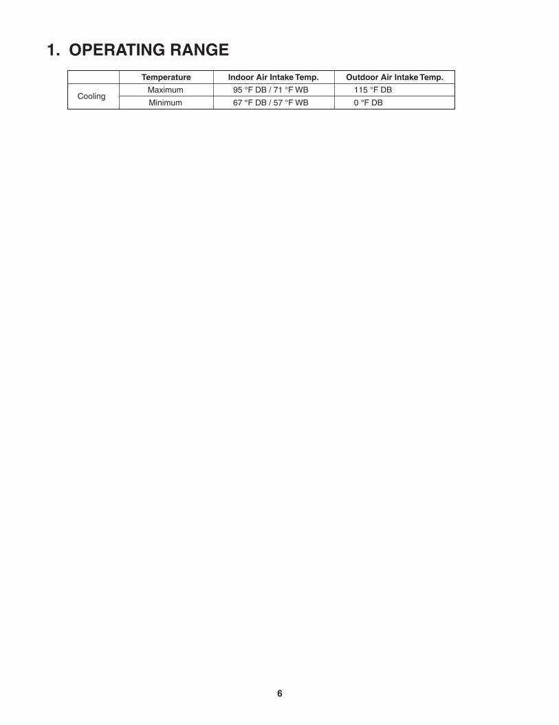
95 °F DB / 71 °F WB
67 °F DB / 57 °F WB
1. OPERATING RANGE
Maximum
Minimum
115 °F DB
0 °F DB
Temperature Indoor Air Intake Temp. Outdoor Air Intake Temp.
Cooling
6
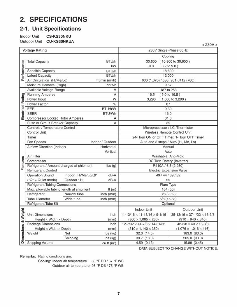
2. SPECIFICATIONS2-1. Unit SpecificationsIndoor Unit CS-KS30NKUOutdoor Unit CU-KS30NKUA
< 230V >
DATA SUBJECT TO CHANGE WITHOUT NOTICE.
Remarks: Rating conditions are:Cooling: Indoor air temperature 80 °F DB / 67 °F WB
Outdoor air temperature 95 °F DB / 75 °F WB
Vertical
dB-AdB-A
Indoor : Hi/Me/Lo/Qt*Outdoor : Hi
Air FilterCompressorRefrigerant / Amount charged at shipment Ibs (g)Refrigerant Control
16.53,290
( 5.0 to 16.5 )( 1,000 to 3,290 )
30,6009.0
( 10,900 to 30,600 )( 3.2 to 9.0 )
Shipping Volume
Cooling
18,60012,000
NetShipping
Package Dimensions
Weight
Height Width Depth
Height Width DepthIbs (kg)Ibs (kg)
cu.ft (m3)
(mm)inch
(mm)
230V Single-Phase 60Hz
inch
187 to 253
Dim
ensi
on
s &
Wei
gh
t
(*Qt = Quiet mode)Refrigerant Tubing Connections
Unit Dimensions
Operation Sound
Ele
ctri
cal R
atin
g
Sensible CapacityLatent Capacity
WPower Input
VA
Available Voltage RangeRunning Amperes
Refrigerant Tube Kit
Narrow tubeWide tube
Refrigerant inch (mm)Tube Diameter inch (mm)
32.039.74.59
(14.5)(18.0)(0.13)
183.0205.015.88
(83.0)(93.0)(0.45)
42-3/8 40 16-3/8(1,076 1,016 416)
(300 1,065 230) (910 940 340)12-7/32 44-7/8 14-31/32
(310 1,140 380)
Outdoor UnitIndoor Unit
11-13/16 41-15/16 9-1/16 35-13/16 37-1/32 13-3/8
3/8 (9.52)5/8 (15.88)
ft (m)Max. allowable tubing length at shipmentFlare Type164 (50)
49 / 44 / 39 / 3255
R410A / 6.5 (2,950)Electric Expansion Valve
Washable, Anti-MoldDC Twin Rotary (Inverter)
ManualAuto
TimerIndoor / OutdoorFan Speeds
24-Hour ON or OFF Timer, 1-Hour OFF TimerAuto and 3 steps / Auto (Hi, Me, Lo)
Airflow Direction (Indoor) Horizontal
Controls / Temperature ControlControl Unit
Microprocessor / I.C. ThermisterWireless Remote Control Unit
Fea
ture
s
Compressor Locked Rotor Amperes
Optional
BTU/h
Per
form
ance
%Power Factor 87
A 31.0
Voltage Rating
BTU/h
kWTotal Capacity
BTU/h
SEER BTU/Wh 16.0
630 (1,070) / 530 (901) /412 (700)Air Circulation (Hi/Me/Lo) ft3/min (m3/h)9.57Moisture Removal (High) Pints/h
EER BTU/h/W 9.30
Fuse or Circuit Breaker Capacity A 35
7
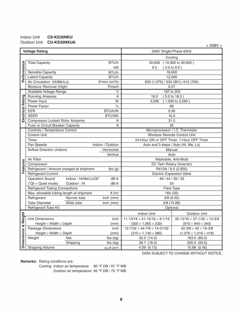
Indoor Unit CS-KS30NKUOutdoor Unit CU-KS30NKUA
< 208V >
DATA SUBJECT TO CHANGE WITHOUT NOTICE.
Vertical
dB-AdB-A
Indoor : Hi/Me/Lo/Qt*Outdoor : Hi
Air FilterCompressorRefrigerant / Amount charged at shipment Ibs (g)Refrigerant Control
Shipping Volume
NetShipping
Package Dimensions
Weight
Height Width Depth
Height Width DepthIbs (kg)Ibs (kg)
cu.ft (m3)
(mm)inch
(mm)
208V Single-Phase 60Hz
inch
Dim
ensi
on
s &
Wei
gh
t
(*Qt = Quiet mode)Refrigerant Tubing Connections
Unit Dimensions
Operation Sound
Ele
ctri
cal R
atin
g
Sensible CapacityLatent Capacity
WPower Input
VA
Available Voltage RangeRunning Amperes
Refrigerant Tube Kit
Narrow tubeWide tube
Refrigerant inch (mm)Tube Diameter inch (mm)
ft (m)Max. allowable tubing length at shipment
TimerIndoor / OutdoorFan Speeds
Airflow Direction (Indoor) Horizontal
Controls / Temperature ControlControl Unit
Fea
ture
s
Compressor Locked Rotor Amperes
BTU/h
Per
form
ance
%Power Factor
A
Voltage Rating
BTU/h
kWTotal Capacity
BTU/h
SEER BTU/Wh
Air Circulation (Hi/Me/Lo) ft3/min (m3/h)Moisture Removal (High) Pints/h
EER BTU/h/W
Fuse or Circuit Breaker Capacity A
18.03,290
( 5.0 to 18.0 )( 1,000 to 3,290 )
30,6009.0
( 10,900 to 30,600 )( 3.2 to 9.0 )
Cooling
18,60012,000
187 to 253
32.039.74.59
(14.5)(18.0)(0.13)
183.0205.015.88
(83.0)(93.0)(0.45)
(300 1,065 230) (910 940 340)
Outdoor UnitIndoor Unit
11-13/16 41-15/16 9-1/16 35-13/16 37-1/32 13-3/8
3/8 (9.52)5/8 (15.88)
Flare Type164 (50)
49 / 44 / 39 / 3255
R410A / 6.5 (2,950)Electric Expansion Valve
Washable, Anti-MoldDC Twin Rotary (Inverter)
ManualAuto
24-Hour ON or OFF Timer, 1-Hour OFF TimerAuto and 3 steps / Auto (Hi, Me, Lo)
Microprocessor / I.C. ThermisterWireless Remote Control Unit
Optional
88
31.016.0
630 (1,070) / 530 (901) /412 (700)9.57
9.30
35
42-3/8 40 16-3/8(1,076 1,016 416)
12-7/32 44-7/8 14-31/32(310 1,140 380)
Remarks: Rating conditions are:Cooling: Indoor air temperature 80 °F DB / 67 °F WB
Outdoor air temperature 95 °F DB / 75 °F WB
8

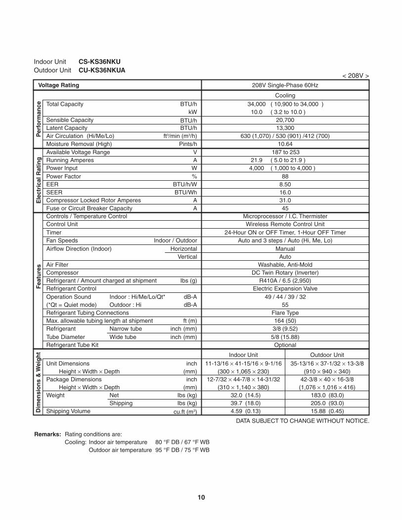
Indoor Unit CS-KS36NKUOutdoor Unit CU-KS36NKUA
< 230V >
DATA SUBJECT TO CHANGE WITHOUT NOTICE.
Vertical
dB-AdB-A
Indoor : Hi/Me/Lo/Qt*Outdoor : Hi
Air FilterCompressorRefrigerant / Amount charged at shipment Ibs (g)Refrigerant Control
Shipping Volume
NetShipping
Package Dimensions
Weight
Height Width Depth
Height Width DepthIbs (kg)Ibs (kg)
cu.ft (m3)
(mm)inch
(mm)
230V Single-Phase 60Hz
inch
Dim
ensi
on
s &
Wei
gh
t
(*Qt = Quiet mode)Refrigerant Tubing Connections
Unit Dimensions
Operation Sound
Ele
ctri
cal R
atin
g
Sensible CapacityLatent Capacity
WPower Input
VA
Available Voltage RangeRunning Amperes
Refrigerant Tube Kit
Narrow tubeWide tube
Refrigerant inch (mm)Tube Diameter inch (mm)
ft (m)Max. allowable tubing length at shipment
TimerIndoor / OutdoorFan Speeds
Airflow Direction (Indoor) Horizontal
Controls / Temperature ControlControl Unit
Fea
ture
s
Compressor Locked Rotor Amperes
BTU/h
Per
form
ance
%Power Factor
A
Voltage Rating
BTU/h
kWTotal Capacity
BTU/h
SEER BTU/Wh
Air Circulation (Hi/Me/Lo) ft3/min (m3/h)Moisture Removal (High) Pints/h
EER BTU/h/W
Fuse or Circuit Breaker Capacity A
20.04,000
( 5.0 to 20.0 )( 1,000 to 4,000 )
34,00010.0
( 10,900 to 34,000 )( 3.2 to 10.0 )
Cooling
20,70013,300
187 to 253
32.039.74.59
(14.5)(18.0)(0.13)
183.0205.015.88
(83.0)(93.0)(0.45)
(300 1,065 230) (910 940 340)
Outdoor UnitIndoor Unit
11-13/16 41-15/16 9-1/16 35-13/16 37-1/32 13-3/8
3/8 (9.52)5/8 (15.88)
Flare Type164 (50)
49 / 44 / 39 / 3255
R410A / 6.5 (2,950)Electric Expansion Valve
Washable, Anti-MoldDC Twin Rotary (Inverter)
ManualAuto
24-Hour ON or OFF Timer, 1-Hour OFF TimerAuto and 3 steps / Auto (Hi, Me, Lo)
Microprocessor / I.C. ThermisterWireless Remote Control Unit
Optional
87
31.016.0
630 (1,070) / 530 (901) /412 (700)10.64
8.50
45
42-3/8 40 16-3/8(1,076 1,016 416)
12-7/32 44-7/8 14-31/32(310 1,140 380)
Remarks: Rating conditions are:Cooling: Indoor air temperature 80 °F DB / 67 °F WB
Outdoor air temperature 95 °F DB / 75 °F WB
9
Indoor Unit CS-KS36NKUOutdoor Unit CU-KS36NKUA
< 208V >
DATA SUBJECT TO CHANGE WITHOUT NOTICE.
Vertical
dB-AdB-A
Indoor : Hi/Me/Lo/Qt*Outdoor : Hi
Air FilterCompressorRefrigerant / Amount charged at shipment Ibs (g)Refrigerant Control
Shipping Volume
Cooling
NetShipping
Package Dimensions
Weight
Height Width Depth
Height Width DepthIbs (kg)Ibs (kg)
cu.ft (m3)
(mm)inch
(mm)
208V Single-Phase 60Hz
inch
Dim
ensi
on
s &
Wei
gh
t
(*Qt = Quiet mode)Refrigerant Tubing Connections
Unit Dimensions
Operation Sound
Ele
ctri
cal R
atin
g
Sensible CapacityLatent Capacity
WPower Input
VA
Available Voltage RangeRunning Amperes
Refrigerant Tube Kit
Narrow tubeWide tube
Refrigerant inch (mm)Tube Diameter inch (mm)
ft (m)Max. allowable tubing length at shipment
TimerIndoor / OutdoorFan Speeds
Airflow Direction (Indoor) Horizontal
Controls / Temperature ControlControl Unit
Fea
ture
s
Compressor Locked Rotor Amperes
BTU/h
Per
form
ance
%Power Factor
A
Voltage Rating
BTU/h
kWTotal Capacity
BTU/h
SEER BTU/Wh
Air Circulation (Hi/Me/Lo) ft3/min (m3/h)Moisture Removal (High) Pints/h
EER BTU/h/W
Fuse or Circuit Breaker Capacity A
21.94,000
( 5.0 to 21.9 )( 1,000 to 4,000 )
34,00010.0
( 10,900 to 34,000 )( 3.2 to 10.0 )
20,70013,300
187 to 253
32.039.74.59
(14.5)(18.0)(0.13)
183.0205.015.88
(83.0)(93.0)(0.45)
(300 1,065 230) (910 940 340)
Outdoor UnitIndoor Unit
11-13/16 41-15/16 9-1/16 35-13/16 37-1/32 13-3/8
3/8 (9.52)5/8 (15.88)
Flare Type164 (50)
49 / 44 / 39 / 3255
R410A / 6.5 (2,950)Electric Expansion Valve
Washable, Anti-MoldDC Twin Rotary (Inverter)
ManualAuto
24-Hour ON or OFF Timer, 1-Hour OFF TimerAuto and 3 steps / Auto (Hi, Me, Lo)
Microprocessor / I.C. ThermisterWireless Remote Control Unit
Optional
88
31.016.0
630 (1,070) / 530 (901) /412 (700)10.64
8.50
45
42-3/8 40 16-3/8(1,076 1,016 416)
12-7/32 44-7/8 14-31/32(310 1,140 380)
Remarks: Rating conditions are:Cooling: Indoor air temperature 80 °F DB / 67 °F WB
Outdoor air temperature 95 °F DB / 75 °F WB
10
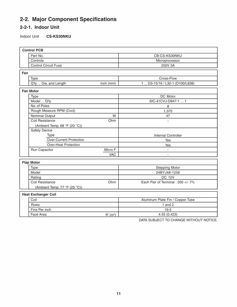
Indoor Unit CS-KS30NKU
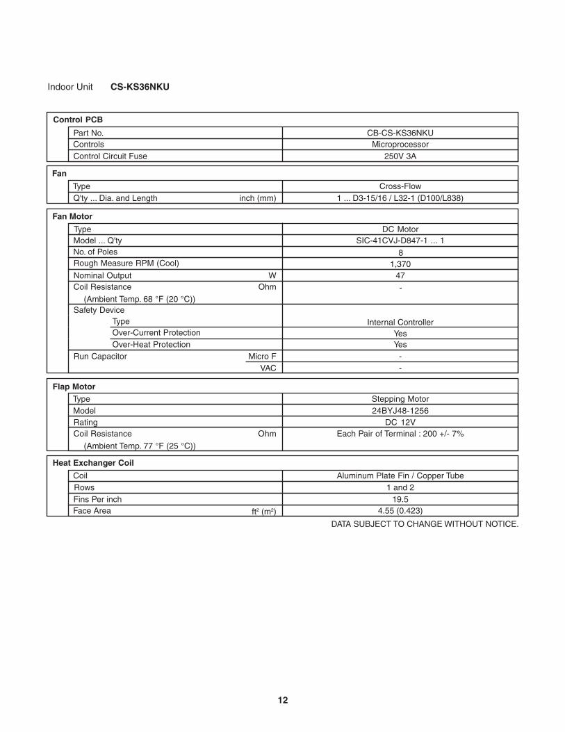
24BYJ48-1256
Flap MotorType Stepping Motor
Rating Model
Coil Resistance Ohm
(Ambient Temp. 77 °F (25 °C))
Each Pair of Terminal : 200 +/- 7%DC 12V
Aluminum Plate Fin / Copper Tube1 and 2
19.54.55 (0.423) Face Area
CoilRowsFins Per inch
Heat Exchanger Coil
ft2 (m2)
DATA SUBJECT TO CHANGE WITHOUT NOTICE.
Yes
Control PCB
Control Circuit Fuse ControlsPart No.
Microprocessor250V 3A
CB-CS-KS30NKU
1 ... D3-15/16 / L32-1 (D100/L838)Cross-Flow
DC MotorSIC-41CVJ-D847-1 ... 1
8
-
471,370
Internal ControllerYes
--
Fan
Q'ty ... Dia. and LengthType
inch (mm)
Fan Motor
Nominal OutputCoil Resistance
Rough Measure RPM (Cool)
TypeModel ... Q'tyNo. of Poles
Safety DeviceTypeOver-Current ProtectionOver-Heat Protection
(Ambient Temp. 68 °F (20 °C))
Run Capacitor Micro FVAC
WOhm
2-2. Major Component Specifications2-2-1. Indoor Unit
11
Indoor Unit CS-KS36NKU
Flap MotorType
Rating Model
Coil Resistance Ohm
(Ambient Temp. 77 °F (25 °C))
Face Area
CoilRowsFins Per inch
Heat Exchanger Coil
ft2 (m2)
DATA SUBJECT TO CHANGE WITHOUT NOTICE.
Control PCB
Control Circuit Fuse ControlsPart No.
Microprocessor250V 3A
CB-CS-KS36NKU
Fan
Q'ty ... Dia. and LengthType
inch (mm)
Fan Motor
Nominal OutputCoil Resistance
Rough Measure RPM (Cool)
TypeModel ... Q'tyNo. of Poles
Safety DeviceType
(Ambient Temp. 68 °F (20 °C))
Run Capacitor Micro FVAC
WOhm
Over-Current ProtectionOver-Heat Protection
24BYJ48-1256Stepping Motor
Each Pair of Terminal : 200 +/- 7%DC 12V
Aluminum Plate Fin / Copper Tube1 and 2
19.54.55 (0.423)
1 ... D3-15/16 / L32-1 (D100/L838)Cross-Flow
DC MotorSIC-41CVJ-D847-1 ... 1
8
-
471,370
Internal ControllerYesYes
--
12
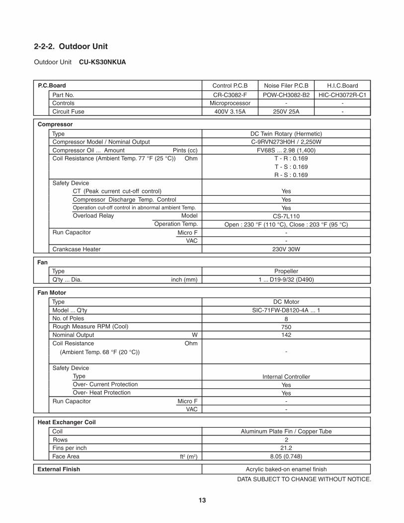
Outdoor Unit CU-KS30NKUA
2-2-2. Outdoor Unit
P.C.Board
Circuit Fuse ControlsPart No.
-250V 25A
POW-CH3082-B2
Noise Filer P.C.B
Microprocessor400V 3.15A
CR-C3082-F
Control P.C.B
--
HIC-CH3072R-C1
H.I.C.Board
DATA SUBJECT TO CHANGE WITHOUT NOTICE.
Pints (cc)
-
Micro FVAC
External Finish Acrylic baked-on enamel finish
FV68S ... 2.98 (1,400)
--
Internal Controller
Yes
Aluminum Plate Fin / Copper Tube2
21.2 Face Area ft2 (m2) 8.05 (0.748)
CoilRowsFins per inch
Heat Exchanger Coil
SIC-71FW-D8120-4A ... 1
Compressor Oil ... Amount
8
142750
Ohm
DC Motor
TypeCompressor Model / Nominal Output
Compressor
Coil Resistance (Ambient Temp. 77 °F (25 °C)) Ohm
DC Twin Rotary (Hermetic)C-9RVN273H0H / 2,250W
T - R :T - S :R - S :
0.1690.1690.169
CT (Peak current cut-off control)Compressor Discharge Temp. ControlOperation cut-off control in abnormal ambient Temp.
Safety Device
Micro FVAC
Run Capacitor
Crankcase Heater
YesYesYes
Overload Relay CS-7L110ModelOperation Temp. Open : 230 °F (110 °C), Close : 203 °F (95 °C)
--
230V 30W
1 ... D19-9/32 (D490)
FanPropeller
Q'ty ... Dia. inch (mm)Type
Type
Over- Heat Protection
(Ambient Temp. 68 °F (20 °C))
Fan Motor
Nominal OutputCoil Resistance
Safety Device
Rough Measure RPM (Cool)
Run Capacitor
TypeModel ... Q'tyNo. of Poles
W
YesOver- Current Protection
13
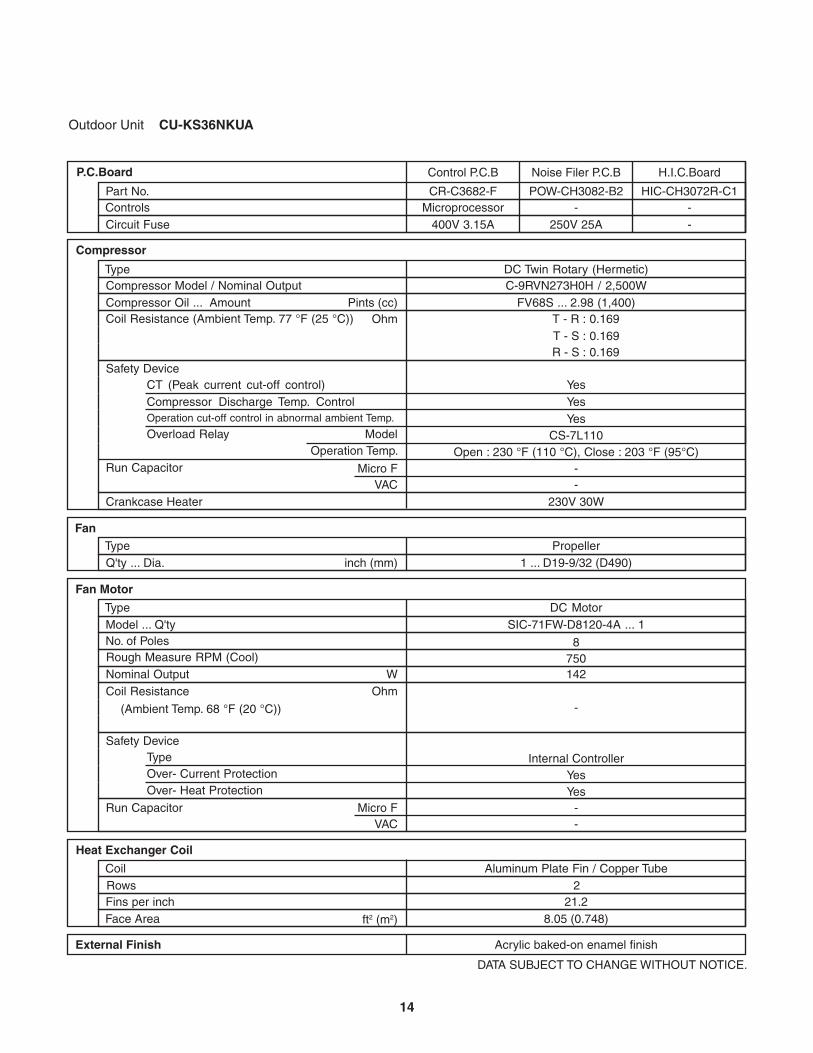
Outdoor Unit CU-KS36NKUA
P.C.Board
Circuit Fuse ControlsPart No.
-250V 25A
POW-CH3082-B2
Noise Filer P.C.B
Microprocessor400V 3.15A
CR-C3682-F
Control P.C.B
--
HIC-CH3072R-C1
H.I.C.Board
DATA SUBJECT TO CHANGE WITHOUT NOTICE.
Pints (cc)
-
Micro FVAC
External Finish Acrylic baked-on enamel finish
FV68S ... 2.98 (1,400)
--
Internal Controller
Yes
Aluminum Plate Fin / Copper Tube2
21.2 Face Area ft2 (m2) 8.05 (0.748)
CoilRowsFins per inch
Heat Exchanger Coil
SIC-71FW-D8120-4A ... 1
Compressor Oil ... Amount
8
142750
Ohm
DC Motor
TypeCompressor Model / Nominal Output
Compressor
Coil Resistance (Ambient Temp. 77 °F (25 °C)) Ohm
DC Twin Rotary (Hermetic)C-9RVN273H0H / 2,500W
T - R :T - S :R - S :
0.1690.1690.169
CT (Peak current cut-off control)Compressor Discharge Temp. ControlOperation cut-off control in abnormal ambient Temp.
Safety Device
Micro FVAC
Run Capacitor
Crankcase Heater
YesYesYes
Overload Relay CS-7L110ModelOperation Temp. Open : 230 °F (110 °C), Close : 203 °F (95°C)
--
230V 30W
1 ... D19-9/32 (D490)
FanPropeller
Q'ty ... Dia. inch (mm)Type
Type
Over- Heat Protection
(Ambient Temp. 68 °F (20 °C))
Fan Motor
Nominal OutputCoil Resistance
Safety Device
Rough Measure RPM (Cool)
Run Capacitor
TypeModel ... Q'tyNo. of Poles
W
YesOver- Current Protection
14
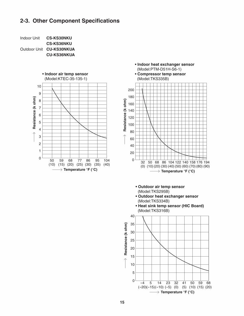
2-3. Other Component Specifications
Indoor Unit CS-KS30NKU CS-KS36NKUOutdoor Unit CU-KS30NKUA CU-KS36NKUA
032 50 68 86 104 122 140 158 176 194(0) (10) (20) (30) (40) (50) (60) (70) (80) (90)
40
60
80
100
120
140
160
180
200
20
50
1
0
2
3
4
5
6
7
8
9
10
59 68 77 86 95 104(10) (15) (20) (25) (30) (35) (40)
• Indoor air temp sensor (Model:KTEC-35-135-1)
• Indoor heat exchanger sensor (Model:PTM-D51H-S6-1)• Compressor temp sensor (Model:TKS335B)
Res
ista
nce
(k
oh
m)
Res
ista
nce
(k
oh
m)
Temperature °F (°C)
• Outdoor air temp sensor (Model:TKS295B)• Outdoor heat exchanger sensor (Model:TKS334B)• Heat sink temp sensor (HIC Board) (Model:TKS316B)
40
35
30
25
20
15
10
5
0-4 5 14 23 32 41 50 59 68
(-20)(-15)(-10) (-5) (0) (5) (10) (15) (20)
Res
ista
nce
(k
oh
m)
Temperature °F (°C)
Temperature °F (°C)
15
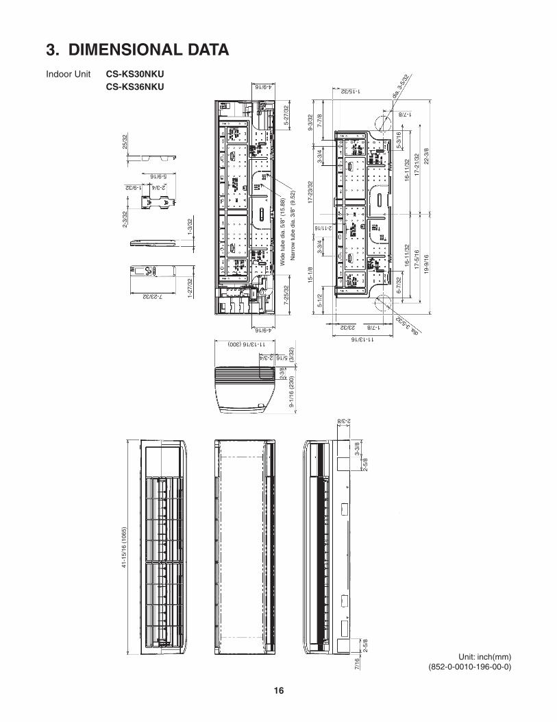
3. DIMENSIONAL DATAIndoor Unit CS-KS30NKU CS-KS36NKU
Unit: inch(mm)(852-0-0010-196-00-0)
41-1
5/16
(10
65)
9-1/
16 (
230)
(3/3
2)7-
25/3
2W
ide
tube
dia
. 5/8
" (1
5.88
)
Nar
row
tube
dia
. 3/8
" (9
.52)
1-27
/32
1-3/
322-3/
3225
/32
5-1/
2
6-7/
3216
-11/
32
17-5
/16
19-9
/16
16-1
1/32
17-2
1/32
22-3
/8
5-3/
16
3-3/
43-
3/4
7-7/
8
15-1
/817
-23/
32
2-11/16
11-13/16
1-7/8dia. 3
-5/3223/32
1-15/32
1-7/8
9-3/
32
5-27
/32
2-3/
8
5/162-3/4
4-9/16
4-9/16
11-13/16 (300)
7-23/32
2-3/4
5-9/16
1-9/32
7/16
2-5/
8
2-3/8
3-3/
82-
5/8
dia.
3-5
/32
16
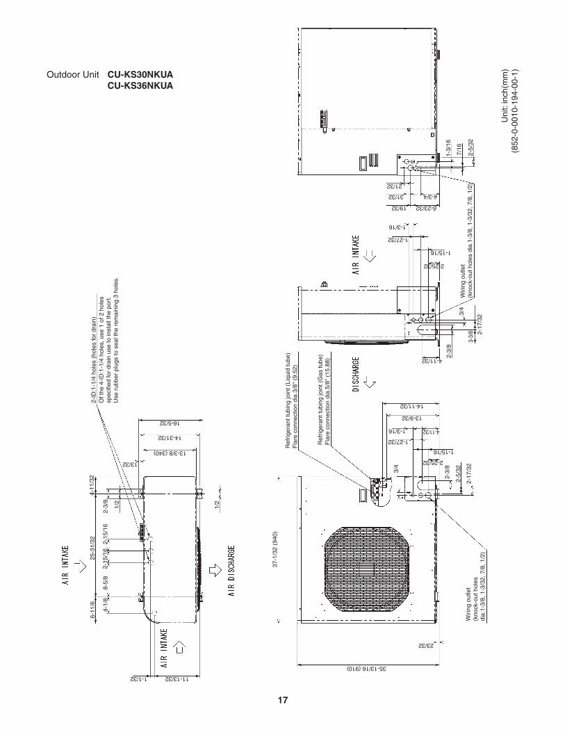
Outdoor Unit CU-KS30NKUA CU-KS36NKUA
Uni
t: in
ch(m
m)
(852
-0-0
010-
194-
00-1
)
4-11/32
2-25/32
1-15/16
6-23/3219/32
31/32 4-3/4
1-3/
16
7/16
2-5/
32
21/32
1-27/32
1-3/16
2-3/
8
3/4
3-3/
8 2-17
/32
Wiri
ng o
utle
t(k
nock
-out
hol
es d
ia.1
-3/8
, 1-3
/32,
7/8
, 1/2
)
6-11
/625
-31/
324-
11/3
2
2-15
/16
2-3/
8
2-ID
:1-1
/4 h
oles
(ho
les
for
drai
n)O
f the
4-I
D:1
-1/4
hol
es, u
se 1
of 2
hol
essp
ecifi
ed fo
r dr
ain
use
to in
stal
l the
por
t.U
se r
ubbe
r pl
ugs
to s
eal t
he r
emai
ning
3 h
oles
.1/
2
1/2
2-15
/16
8-5/
84-
1/8
37-1
/32
(940
)
Ref
riger
ant t
ubin
g jo
int (
Liqu
id tu
be)
Fla
re c
onne
ctio
n di
a.3/
8" (
9.52
)
Ref
riger
ant t
ubin
g jo
int (
Gas
tube
)F
lare
con
nect
ion
dia.
5/8"
(15
.88)
2-3/
8
3/4
1-15/16
1-27/32
1-3/16 4-11/32
13-9/32
14-11/32
Wiri
ng o
utle
t(k
nock
-out
hol
esdi
a.1-
3/8,
1-3
/32,
7/8
, 1/2
)
2-25/32
2-5/
32
2-17
/32
35-13/16 (910)
23/32
1-1/32
13/32
13-3/8 (340)
14-31/32
16-5/32
11-13/32
17

Wide tubeservicevalveWide tube
NarrowtubeservicevalveNarrow tube
Hea
t exc
hang
er
Hea
t exc
hang
er
Cooling cycle
Indoor unit Outdoor unit
Electricexpansion
valve
Strainer
M
O.D5/8"
(15.88 mm)
O.D.3/8"
(9.52 mm)
4. REFRIGERANT FLOW DIAGRAM4-1. Refrigerant Flow DiagramIndoor Unit CS-KS30NKU CS-KS36NKU
Outdoor Unit CU-KS30NKUA CU-KS36NKUA
Com
pres
sorMain
AccumulatorSubAccumulator
Muffler
H.P.
High pressureswitch
18
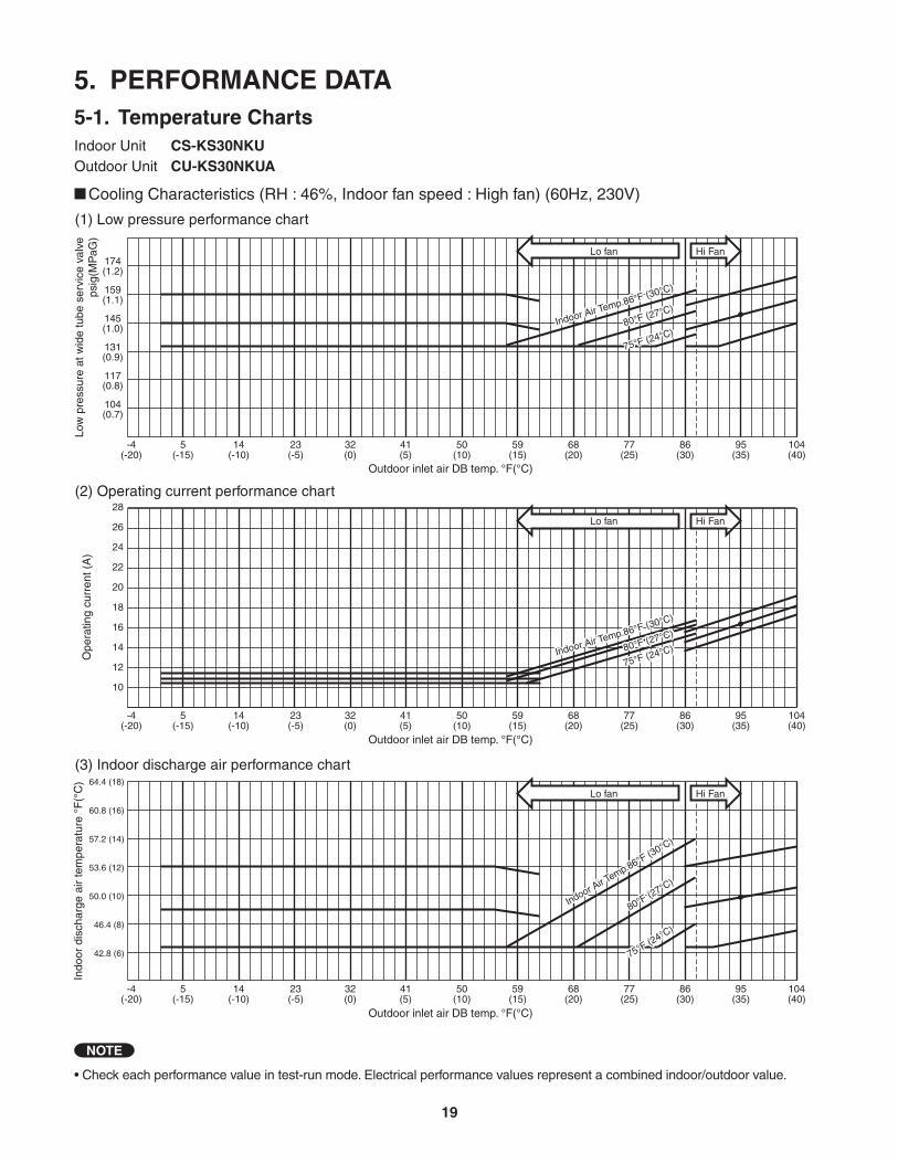
5. PERFORMANCE DATA5-1. Temperature ChartsIndoor Unit CS-KS30NKUOutdoor Unit CU-KS30NKUA
• Check each performance value in test-run mode. Electrical performance values represent a combined indoor/outdoor value.
NOTE
Cooling Characteristics (RH : 46%, Indoor fan speed : High fan) (60Hz, 230V)
(1) Low pressure performance chart
(2) Operating current performance chart
(3) Indoor discharge air performance chart
-4(-20)
5(-15)
14(-10)
23(-5)
32(0)
41(5)
50(10)
59(15)
68(20)
77(25)
86(30)
95(35)
104(40)
Outdoor inlet air DB temp. °F(°C)
Outdoor inlet air DB temp. °F(°C)
Outdoor inlet air DB temp. °F(°C)
Ope
ratin
g cu
rren
t (A
)In
door
dis
char
ge a
ir te
mpe
ratu
re °
F(°
C)
Low
pre
ssur
e at
wid
e tu
be s
ervi
ce v
alve
psig
(MP
aG)
-4(-20)
5(-15)
14(-10)
23(-5)
32(0)
41(5)
50(10)
59(15)
68(20)
77(25)
86(30)
95(35)
104(40)
-4(-20)
5(-15)
14(-10)
23(-5)
32(0)
41(5)
50(10)
59(15)
68(20)
77(25)
86(30)
95(35)
104(40)
57.2 (14)
64.4 (18)
60.8 (16)
53.6 (12)
50.0 (10)
46.4 (8)
42.8 (6)
10
12
14
16
18
20
22
24
26
28
104(0.7)
117(0.8)
131(0.9)
145(1.0)
159(1.1)
174(1.2)
Hi FanLo fan
Hi FanLo fan
Hi FanLo fan
Indoor Air Temp.86°F (30°C)
80°F (27°C)
75°F (24°C)
Indoor Air Temp.86°F (30°C)
80°F (27°C)
75°F (24°C)
Indoor Air Temp.86°F (30°C)
80°F (27°C)
75°F (24°C)
Indoor Air Temp.86°F (30°C)
80°F (27°C)
75°F (24°C)
Indoor Air T
emp.86°F (30°C)
80°F (27°C)
75°F (24°C)
Indoor Air T
emp.86°F (30°C)
80°F (27°C)
75°F (24°C)
19
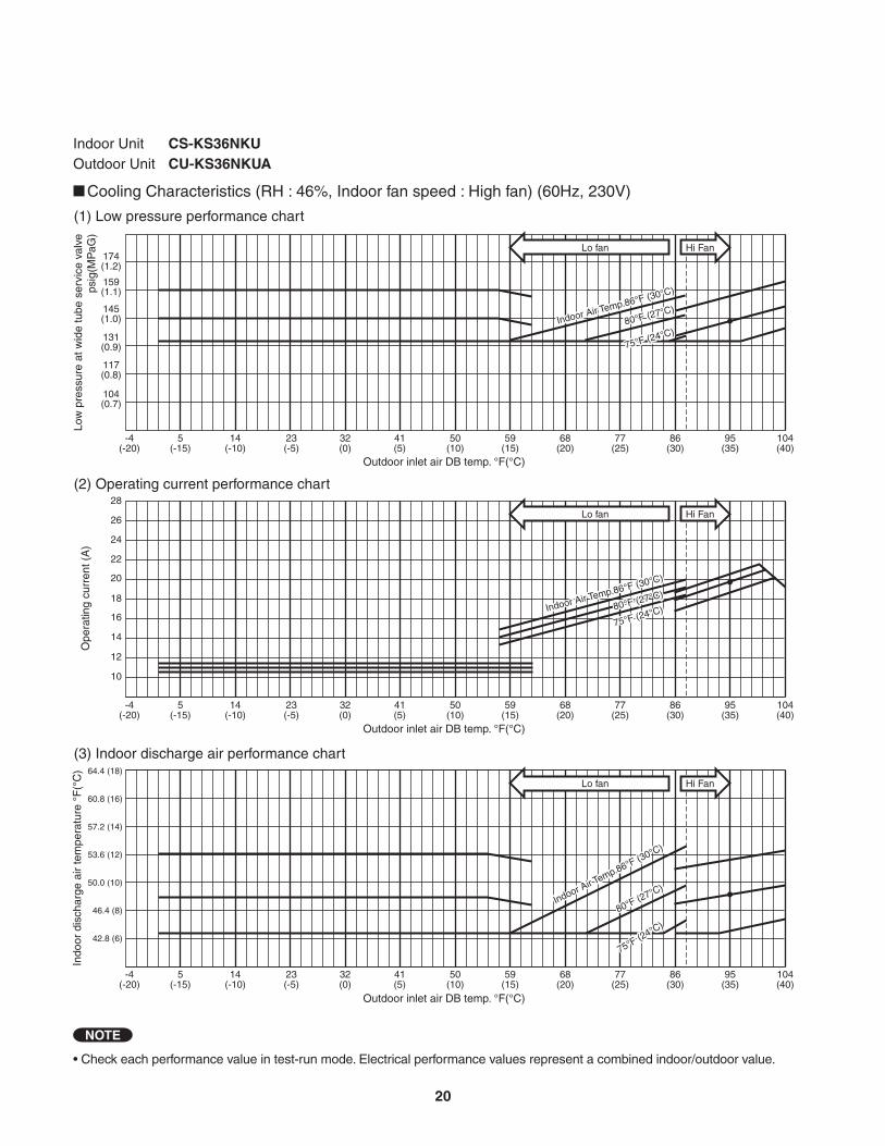
Indoor Unit CS-KS36NKUOutdoor Unit CU-KS36NKUA
Cooling Characteristics (RH : 46%, Indoor fan speed : High fan) (60Hz, 230V)
• Check each performance value in test-run mode. Electrical performance values represent a combined indoor/outdoor value.
NOTE
(1) Low pressure performance chart
(2) Operating current performance chart
(3) Indoor discharge air performance chart
-4(-20)
5(-15)
14(-10)
23(-5)
32(0)
41(5)
50(10)
59(15)
68(20)
77(25)
86(30)
95(35)
104(40)
Outdoor inlet air DB temp. °F(°C)
Outdoor inlet air DB temp. °F(°C)
Outdoor inlet air DB temp. °F(°C)
Ope
ratin
g cu
rren
t (A
)In
door
dis
char
ge a
ir te
mpe
ratu
re °
F(°
C)
Low
pre
ssur
e at
wid
e tu
be s
ervi
ce v
alve
psig
(MP
aG)
-4(-20)
5(-15)
14(-10)
23(-5)
32(0)
41(5)
50(10)
59(15)
68(20)
77(25)
86(30)
95(35)
104(40)
-4(-20)
5(-15)
14(-10)
23(-5)
32(0)
41(5)
50(10)
59(15)
68(20)
77(25)
86(30)
95(35)
104(40)
57.2 (14)
60.8 (16)
64.4 (18)
53.6 (12)
50.0 (10)
46.4 (8)
42.8 (6)
10
12
14
16
18
20
22
24
26
28
104(0.7)
117(0.8)
131(0.9)
145(1.0)
159(1.1)
174(1.2)
Hi FanLo fan
Hi FanLo fan
Hi FanLo fan
Indoor Air Temp.86°F (30°C)
80°F (27°C)
75°F (24°C)
Indoor Air Temp.86°F (30°C)
80°F (27°C)
75°F (24°C)
Indoor Air Temp.86°F (30°C)
80°F (27°C)
75°F (24°C)
Indoor Air Temp.86°F (30°C)
80°F (27°C)
75°F (24°C)
Indoor Air Temp.86°F (30°C)
80°F (27°C)
75°F (24°C)
Indoor Air Temp.86°F (30°C)
80°F (27°C)
75°F (24°C)
20
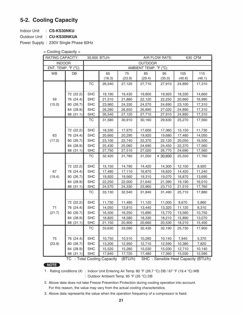
1. Rating conditions (#) : Indoor Unit Entering Air Temp. 80 °F (26.7 °C) DB / 67 °F (19.4 °C) WB: Outdoor Ambient Temp. 95 °F (35 °C) DB
2.
3. Above data represents the value when the operation frequency of a compressor is fixed.
Above data does not take Freeze Prevention Protection during cooling operation into account. For this reason, the value may vary from the actual cooling characteristics.
NOTE
< Cooling Capacity >
Indoor Unit : CS-KS30NKU
Outdoor Unit : CU-KS30NKUA
Power Supply : 230V Single Phase 60Hz
5-2. Cooling Capacity
RATING CAPACITY: 30,600 BTU/h AIR FLOW RATE: 630 CFM
INDOOR OUTDOORENT. TEMP. oF (oC) AMBIENT TEMP. oF (oC)
WB DB 65 75 85 95 105 115(18.3) (23.9) (29.4) (35.0) (40.6) (46.1)
TC 26,540 27,120 27,710 27,910 24,890 17,310CI 2.07 2.43 2.79 3.01 3.04 2.40
72 (22.2) SHC 19,190 19,430 19,800 19,920 18,330 14,66059 76 (24.4) SHC 21,510 21,880 22,120 22,250 20,660 16,990
(15.0) 80 (26.7) SHC 23,960 24,330 24,570 24,690 23,100 17,31084 (28.9) SHC 26,280 26,650 26,890 27,020 24,890 17,31088 (31.1) SHC 26,540 27,120 27,710 27,910 24,890 17,310
TC 31,580 30,910 30,160 29,630 25,270 17,560CI 2.12 2.48 2.85 3.07 3.04 2.40
72 (22.2) SHC 18,330 17,970 17,600 17,360 15,150 11,73063 76 (24.4) SHC 20,660 20,290 19,920 19,680 17,480 14,050
(17.2) 80 (26.7) SHC 23,100 22,740 22,370 22,120 20,050 16,50084 (28.9) SHC 25,430 25,060 24,690 24,450 22,370 17,56088 (31.1) SHC 27,750 27,510 27,020 26,770 24,690 17,560
TC 32,420 31,780 31,050 # 30,600 25,550 17,760CI 2.17 2.55 2.93 3.14 3.04 2.40
72 (22.2) SHC 15,150 14,790 14,420 14,300 12,100 8,92067 76 (24.4) SHC 17,480 17,110 16,870 16,620 14,420 11,240
(19.4) 80 (26.7) SHC 19,920 19,560 19,310 19,070 16,870 13,690
84 (28.9) SHC 22,250 22,000 21,640 21,390 19,190 16,01088 (31.1) SHC 24,570 24,330 23,960 23,710 21,510 17,760
TC 33,130 32,540 31,840 31,490 25,710 17,880CI 2.24 2.63 3.02 3.22 3.04 2.40
72 (22.2) SHC 11,730 11,480 11,120 11,000 8,670 5,86071 76 (24.4) SHC 14,050 13,810 13,440 13,320 11,120 8,310
(21.7) 80 (26.7) SHC 16,500 16,250 15,890 15,770 13,560 10,750
84 (28.9) SHC 18,820 18,580 18,330 18,210 15,890 13,07088 (31.1) SHC 21,150 20,900 20,660 20,530 18,210 15,400
TC 33,630 33,090 32,430 32,190 25,730 17,900CI 2.31 2.71 3.11 3.30 3.04 2.40
75 76 (24.4) SHC 10,750 10,510 10,260 10,140 7,940 5,370(23.9) 80 (26.7) SHC 13,200 12,950 12,710 12,590 10,380 7,820
84 (28.9) SHC 15,520 15,280 15,030 15,030 12,710 10,14088 (31.1) SHC 17,840 17,720 17,480 17,360 15,030 12,590
TC : Total Cooling Capacity (BTU/h) SHC : Sensible Heat Capacity (BTU/h)
21
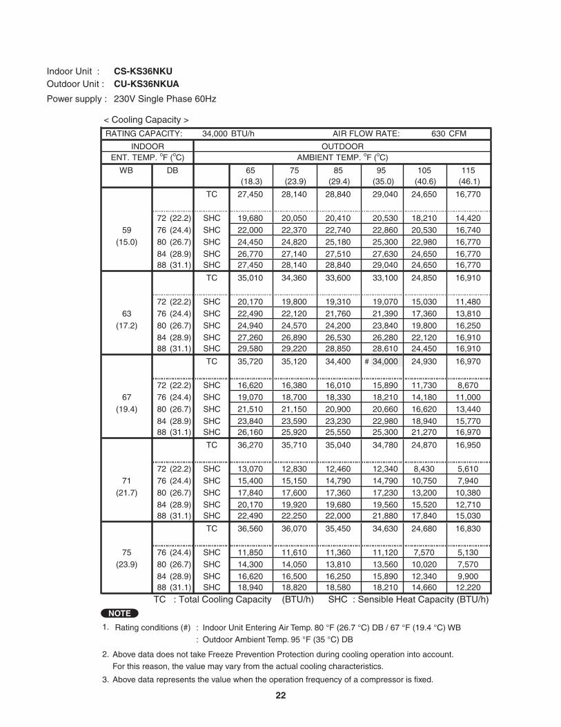
Outdoor Unit : CU-KS36NKUAIndoor Unit : CS-KS36NKU
Power supply : 230V Single Phase 60Hz
RATING CAPACITY: 34,000 BTU/h AIR FLOW RATE: 630 CFM
INDOOR OUTDOORENT. TEMP. oF (oC) AMBIENT TEMP. oF (oC)
WB DB 65 75 85 95 105 115(18.3) (23.9) (29.4) (35.0) (40.6) (46.1)
TC 27,450 28,140 28,840 29,040 24,650 16,770CI 2.61 3.02 3.43 3.67 3.22 2.48
72 (22.2) SHC 19,680 20,050 20,410 20,530 18,210 14,42059 76 (24.4) SHC 22,000 22,370 22,740 22,860 20,530 16,740
(15.0) 80 (26.7) SHC 24,450 24,820 25,180 25,300 22,980 16,77084 (28.9) SHC 26,770 27,140 27,510 27,630 24,650 16,77088 (31.1) SHC 27,450 28,140 28,840 29,040 24,650 16,770
TC 35,010 34,360 33,600 33,100 24,850 16,910CI 2.68 3.10 3.53 3.76 3.22 2.48
72 (22.2) SHC 20,170 19,800 19,310 19,070 15,030 11,48063 76 (24.4) SHC 22,490 22,120 21,760 21,390 17,360 13,810
(17.2) 80 (26.7) SHC 24,940 24,570 24,200 23,840 19,800 16,25084 (28.9) SHC 27,260 26,890 26,530 26,280 22,120 16,91088 (31.1) SHC 29,580 29,220 28,850 28,610 24,450 16,910
TC 35,720 35,120 34,400 # 34,000 24,930 16,970CI 2.77 3.20 3.64 3.85 3.22 2.48
72 (22.2) SHC 16,620 16,380 16,010 15,890 11,730 8,67067 76 (24.4) SHC 19,070 18,700 18,330 18,210 14,180 11,000
(19.4) 80 (26.7) SHC 21,510 21,150 20,900 20,660 16,620 13,440
84 (28.9) SHC 23,840 23,590 23,230 22,980 18,940 15,77088 (31.1) SHC 26,160 25,920 25,550 25,300 21,270 16,970
TC 36,270 35,710 35,040 34,780 24,870 16,950CI 2.87 3.31 3.76 3.96 3.22 2.48
72 (22.2) SHC 13,070 12,830 12,460 12,340 8,430 5,61071 76 (24.4) SHC 15,400 15,150 14,790 14,790 10,750 7,940
(21.7) 80 (26.7) SHC 17,840 17,600 17,360 17,230 13,200 10,380
84 (28.9) SHC 20,170 19,920 19,680 19,560 15,520 12,71088 (31.1) SHC 22,490 22,250 22,000 21,880 17,840 15,030
TC 36,560 36,070 35,450 34,630 24,680 16,830CI 2.97 3.42 3.88 3.98 3.22 2.48
75 76 (24.4) SHC 11,850 11,610 11,360 11,120 7,570 5,130(23.9) 80 (26.7) SHC 14,300 14,050 13,810 13,560 10,020 7,570
84 (28.9) SHC 16,620 16,500 16,250 15,890 12,340 9,90088 (31.1) SHC 18,940 18,820 18,580 18,210 14,660 12,220
TC : Total Cooling Capacity (BTU/h) SHC : Sensible Heat Capacity (BTU/h)
< Cooling Capacity >
1. Rating conditions (#) : Indoor Unit Entering Air Temp. 80 °F (26.7 °C) DB / 67 °F (19.4 °C) WB: Outdoor Ambient Temp. 95 °F (35 °C) DB
2.
3. Above data represents the value when the operation frequency of a compressor is fixed.
Above data does not take Freeze Prevention Protection during cooling operation into account. For this reason, the value may vary from the actual cooling characteristics.
NOTE
22
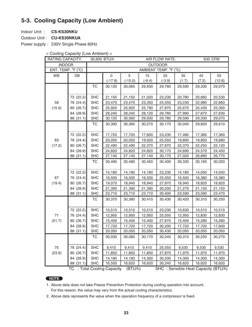
Outdoor Unit : CU-KS30NKUA
Indoor Unit : CS-KS30NKU
Power supply : 230V Single Phase 60Hz
RATING CAPACITY: 30,600 BTU/h AIR FLOW RATE: 630 CFM
INDOOR OUTDOOR ENT. TEMP. oF (oC) AMBIENT TEMP. oF (oC)
WB DB 0 5 15 25 35 45 55(-17.8) (-15.0) (-9.4) (-3.9) (1.7) (7.2) (12.8)
TC 30,120 30,060 29,930 29,780 29,590 29,330 29,070CI 0.05 0.19 0.47 0.74 1.01 1.33 1.61
72 (22.2) SHC 21,150 21,150 21,020 23,230 20,780 20,660 20,53059 76 (24.4) SHC 23,470 23,470 23,350 25,550 23,230 22,980 22,860
(15.0) 80 (26.7) SHC 25,920 25,920 25,790 27,870 25,670 25,430 25,30084 (28.9) SHC 28,240 28,240 28,120 29,780 27,990 27,870 27,63088 (31.1) SHC 30,120 30,060 29,930 29,780 29,590 29,330 29,070
TC 30,390 30,360 30,270 30,170 30,040 29,820 29,610CI 0.12 0.25 0.52 0.79 1.06 1.38 1.66
72 (22.2) SHC 17,720 17,720 17,600 23,230 17,480 17,360 17,360
63 76 (24.4) SHC 20,050 20,050 19,920 25,550 19,800 19,800 19,680(17.2) 80 (26.7) SHC 22,490 22,490 22,370 27,870 22,370 22,250 22,120
84 (28.9) SHC 24,820 24,820 24,820 30,170 24,690 24,570 24,45088 (31.1) SHC 27,140 27,140 27,140 30,170 27,020 26,890 26,770
TC 30,490 30,480 30,450 30,400 30,330 30,160 30,020CI 0.20 0.33 0.60 0.86 1.13 1.45 1.73
72 (22.2) SHC 14,180 14,180 14,180 23,230 14,180 14,050 14,050
67 76 (24.4) SHC 16,500 16,500 16,500 25,550 16,500 16,380 16,380(19.4) 80 (26.7) SHC 19,070 18,940 18,940 27,870 18,940 18,820 18,820
84 (28.9) SHC 21,390 21,390 21,390 30,200 21,270 21,150 21,15088 (31.1) SHC 23,710 23,710 23,710 30,400 23,590 23,590 23,470
TC 30,370 30,380 30,410 30,430 30,420 30,310 30,250CI 0.31 0.43 0.69 0.95 1.21 1.54 1.81
72 (22.2) SHC 10,510 10,510 10,510 23,230 10,630 10,510 10,51071 76 (24.4) SHC 12,950 12,950 12,950 25,550 12,950 12,830 12,830
(21.7) 80 (26.7) SHC 15,400 15,400 15,400 27,870 15,400 15,280 15,28084 (28.9) SHC 17,720 17,720 17,720 30,200 17,720 17,720 17,60088 (31.1) SHC 20,050 20,050 20,050 30,430 20,050 20,050 20,050
TC 30,030 30,080 30,170 30,240 30,310 30,250 30,270CI 0.42 0.55 0.79 1.04 1.30 1.62 1.89
75 76 (24.4) SHC 9,410 9,410 9,410 25,550 9,530 9,530 9,530(23.9) 80 (26.7) SHC 11,850 11,850 11,850 27,870 11,970 11,970 11,970
84 (28.9) SHC 14,180 14,180 14,300 30,200 14,300 14,300 14,30088 (31.1) SHC 16,500 16,620 16,620 30,240 16,620 16,620 16,620
TC : Total Cooling Capacity (BTU/h) SHC : Sensible Heat Capacity (BTU/h)
5-3. Cooling Capacity (Low Ambient)
1.
2. Above data represents the value when the operation frequency of a compressor is fixed.
Above data does not take Freeze Prevention Protection during cooling operation into account. For this reason, the value may vary from the actual cooling characteristics.
NOTE
< Cooling Capacity (Low Ambient) >
23
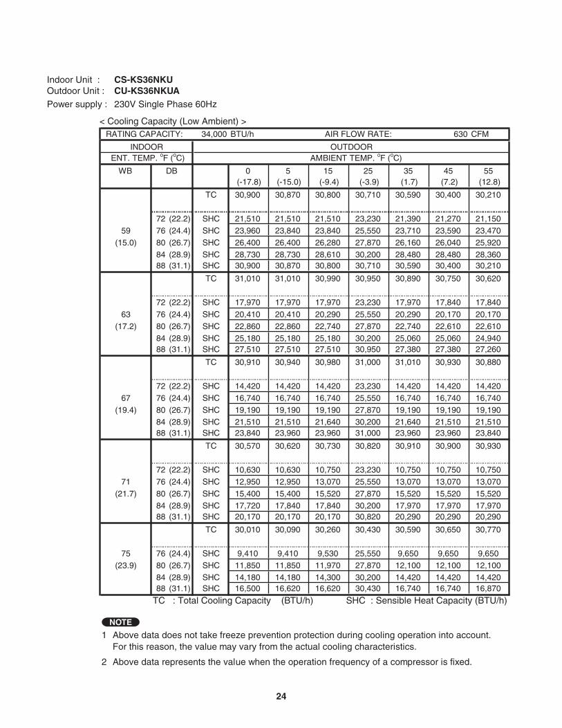
Outdoor Unit : CU-KS36NKUAIndoor Unit : CS-KS36NKU
Power supply : 230V Single Phase 60Hz
-1 RATING CAPACITY: 34,000 BTU/h AIR FLOW RATE: 630 CFM
INDOOR OUTDOOR ENT. TEMP. oF (oC) AMBIENT TEMP. oF (oC)
WB DB 0 5 15 25 35 45 55(-17.8) (-15.0) (-9.4) (-3.9) (1.7) (7.2) (12.8)
TC 30,900 30,870 30,800 30,710 30,590 30,400 30,210CI 0.22 0.36 0.65 0.93 1.22 1.55 1.84
72 (22.2) SHC 21,510 21,510 21,510 23,230 21,390 21,270 21,15059 76 (24.4) SHC 23,960 23,840 23,840 25,550 23,710 23,590 23,470
(15.0) 80 (26.7) SHC 26,400 26,400 26,280 27,870 26,160 26,040 25,92084 (28.9) SHC 28,730 28,730 28,610 30,200 28,480 28,480 28,36088 (31.1) SHC 30,900 30,870 30,800 30,710 30,590 30,400 30,210
TC 31,010 31,010 30,990 30,950 30,890 30,750 30,620CI 0.30 0.44 0.72 1.00 1.28 1.62 1.91
72 (22.2) SHC 17,970 17,970 17,970 23,230 17,970 17,840 17,840
63 76 (24.4) SHC 20,410 20,410 20,290 25,550 20,290 20,170 20,170(17.2) 80 (26.7) SHC 22,860 22,860 22,740 27,870 22,740 22,610 22,610
84 (28.9) SHC 25,180 25,180 25,180 30,200 25,060 25,060 24,94088 (31.1) SHC 27,510 27,510 27,510 30,950 27,380 27,380 27,260
TC 30,910 30,940 30,980 31,000 31,010 30,930 30,880CI 0.40 0.54 0.81 1.08 1.36 1.70 1.99
72 (22.2) SHC 14,420 14,420 14,420 23,230 14,420 14,420 14,420
67 76 (24.4) SHC 16,740 16,740 16,740 25,550 16,740 16,740 16,740(19.4) 80 (26.7) SHC 19,190 19,190 19,190 27,870 19,190 19,190 19,190
84 (28.9) SHC 21,510 21,510 21,640 30,200 21,640 21,510 21,51088 (31.1) SHC 23,840 23,960 23,960 31,000 23,960 23,960 23,840
TC 30,570 30,620 30,730 30,820 30,910 30,900 30,930CI 0.52 0.65 0.92 1.18 1.45 1.79 2.08
72 (22.2) SHC 10,630 10,630 10,750 23,230 10,750 10,750 10,75071 76 (24.4) SHC 12,950 12,950 13,070 25,550 13,070 13,070 13,070
(21.7) 80 (26.7) SHC 15,400 15,400 15,520 27,870 15,520 15,520 15,52084 (28.9) SHC 17,720 17,840 17,840 30,200 17,970 17,970 17,97088 (31.1) SHC 20,170 20,170 20,170 30,820 20,290 20,290 20,290
TC 30,010 30,090 30,260 30,430 30,590 30,650 30,770CI 0.66 0.78 1.04 1.29 1.55 1.89 2.17
75 76 (24.4) SHC 9,410 9,410 9,530 25,550 9,650 9,650 9,650(23.9) 80 (26.7) SHC 11,850 11,850 11,970 27,870 12,100 12,100 12,100
84 (28.9) SHC 14,180 14,180 14,300 30,200 14,420 14,420 14,42088 (31.1) SHC 16,500 16,620 16,620 30,430 16,740 16,740 16,870
TC : Total Cooling Capacity (BTU/h) SHC : Sensible Heat Capacity (BTU/h)CI : Compressor Input (kW)
1
2 Above data represents the value when the operation frequency of a compressor is fixed.
Above data does not take freeze prevention protection during cooling operation into account.For this reason, the value may vary from the actual cooling characteristics.
NOTE
< Cooling Capacity (Low Ambient) >
24
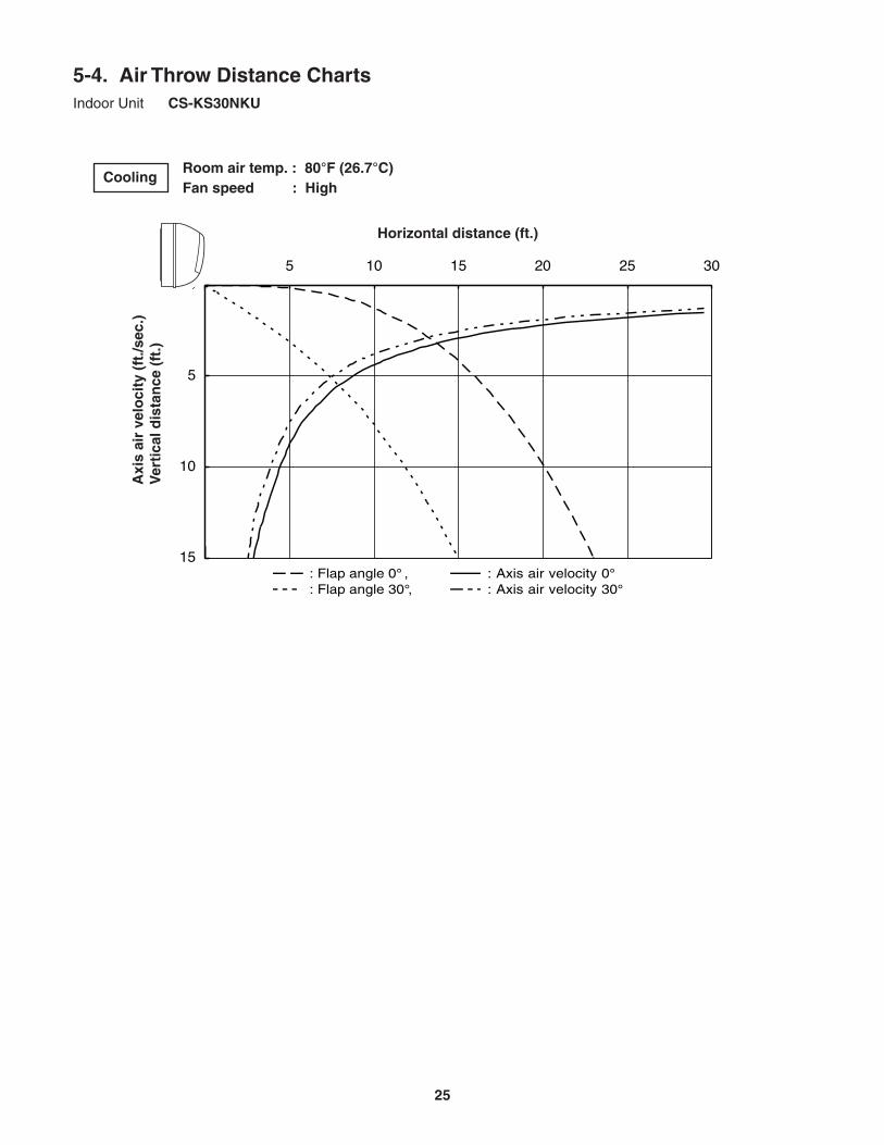
Horizontal distance (ft.)
Axi
s ai
r ve
loci
ty (
ft./s
ec.)
Ver
tica
l dis
tan
ce (
ft.)
Room air temp. : 80°F (26.7°C)Fan speed : High
Cooling
: Flap angle 0 , : Axis air velocity 0 : Flap angle 30 , : Axis air velocity 30
5-4. Air Throw Distance ChartsIndoor Unit CS-KS30NKU
0
5
10
15
0 5 10 15 20 25 30
25
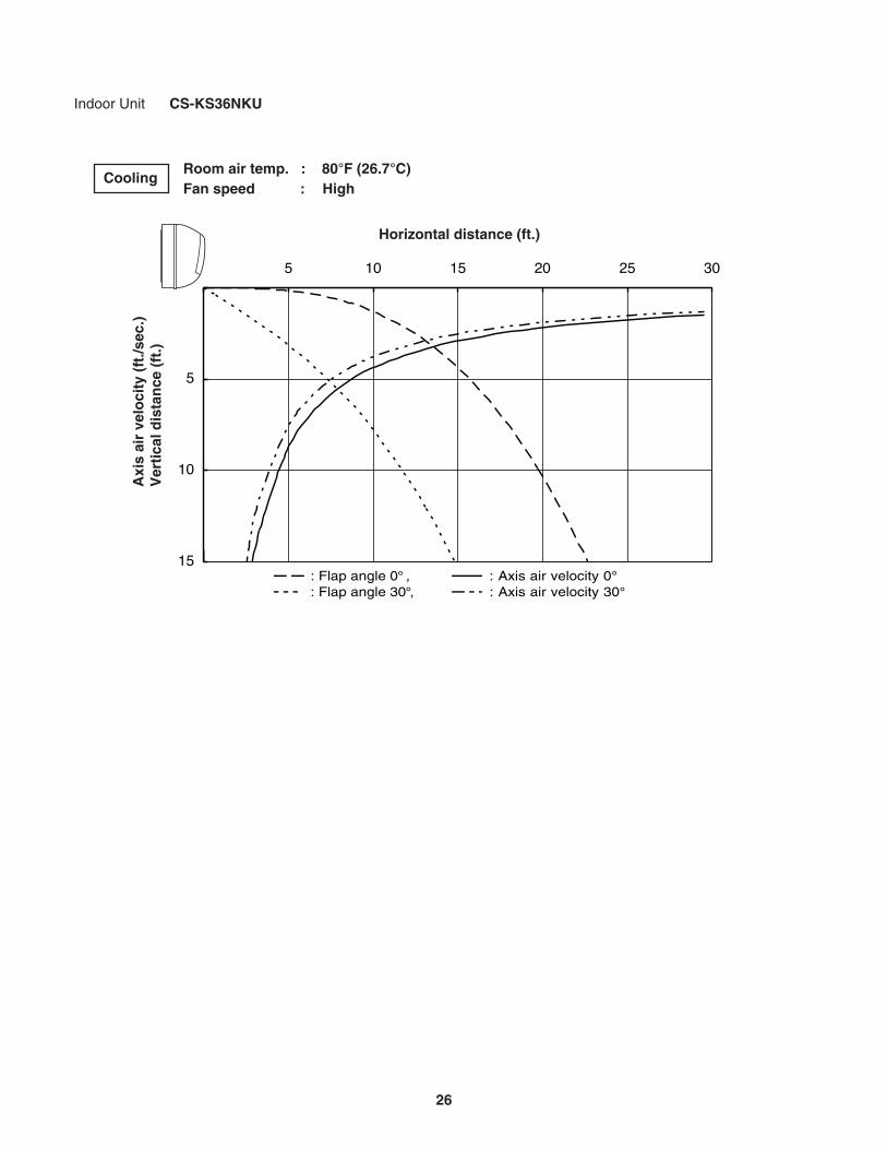
Horizontal distance (ft.)
Axi
s ai
r ve
loci
ty (
ft./s
ec.)
Ver
tica
l dis
tan
ce (
ft.)
Room air temp. : 80°F (26.7°C)Fan speed : High
Cooling
: Flap angle 0 , : Axis air velocity 0 : Flap angle 30 , : Axis air velocity 30
Indoor Unit CS-KS36NKU
0
5
10
15
0 5 10 15 20 25 30
26
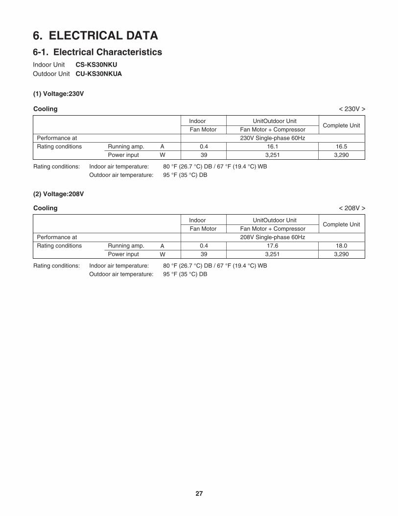
6. ELECTRICAL DATA6-1. Electrical CharacteristicsIndoor Unit CS-KS30NKUOutdoor Unit CU-KS30NKUA
Indoor UnitOutdoor UnitFan Motor Fan Motor + Compressor
Performance at 230V Single-phase 60Hz
Rating conditions Running amp. A 0.4Power input W
AW
3916.1
3,251
Rating conditions: Indoor air temperature: 80 °F (26.7 °C) DB / 67 °F (19.4 °C) WB Outdoor air temperature: 95 °F (35 °C) DB
Cooling
16.53,290
Indoor UnitOutdoor UnitFan Motor Fan Motor + Compressor
Performance at 208V Single-phase 60HzRating conditions Running amp. 0.4
Power input 3917.6
3,251
Cooling
< 230V >
< 208V >
(2) Voltage:208V
(1) Voltage:230V
18.03,290
Rating conditions: Indoor air temperature: 80 °F (26.7 °C) DB / 67 °F (19.4 °C) WB Outdoor air temperature: 95 °F (35 °C) DB
Complete Unit
Complete Unit
27
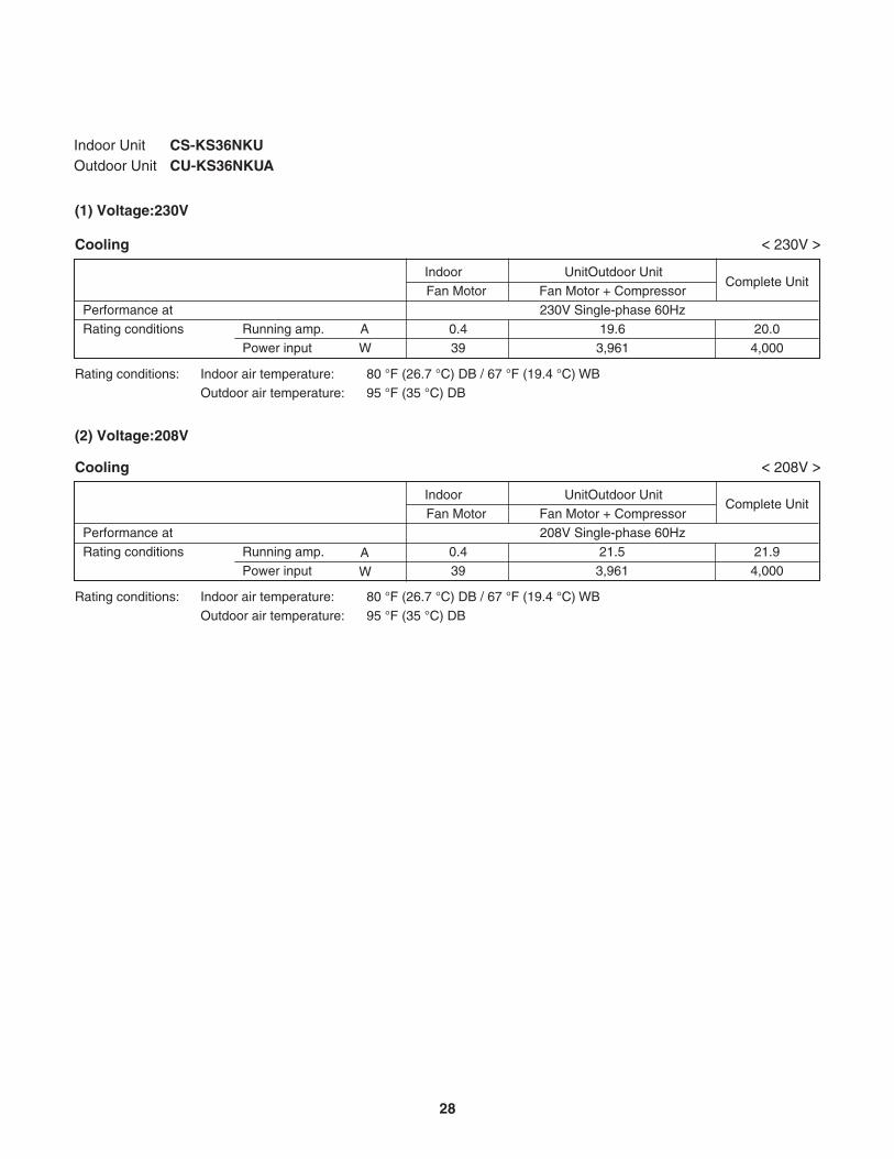
Indoor Unit CS-KS36NKUOutdoor Unit CU-KS36NKUA
Indoor UnitOutdoor UnitFan Motor Fan Motor + Compressor
Performance at 230V Single-phase 60Hz
Rating conditions Running amp. A 0.4Power input W
AW
3919.6
3,961
Rating conditions: Indoor air temperature: 80 °F (26.7 °C) DB / 67 °F (19.4 °C) WB Outdoor air temperature: 95 °F (35 °C) DB
Cooling
20.04,000
Indoor UnitOutdoor UnitFan Motor Fan Motor + Compressor
Performance at 208V Single-phase 60HzRating conditions Running amp. 0.4
Power input 3921.5
3,961
Cooling
< 230V >
< 208V >
(2) Voltage:208V
(1) Voltage:230V
21.94,000
Rating conditions: Indoor air temperature: 80 °F (26.7 °C) DB / 67 °F (19.4 °C) WB Outdoor air temperature: 95 °F (35 °C) DB
Complete Unit
Complete Unit
28
CONTROLLER
IND
LA
MP
AS
SY1
2
45
12
433
5
123
9
123
45
45
67
67
8 89
123
9
123
45
45
67
67
8 89
LAMP9P (WHT)
12
12
COIL2P (WHT)
ROOM/UV4P (WHT)S-LINK (RAC)
4P (BLU)
FLAP5P (WHT)
GND2P (WHT)
1234
1234
1234
WHTBLKBLKBLKBLKBLKBLKBLKBLK
FLAP MOTOR
EVAPORATOR GND
REDORGYELPNKBLU
12
67
12
655
7
DCM7P (WHT)
RED
WHTYEL
4433
BLK
BLU
4 5 61 2 3
T106P (BLU)
AC IN
TO
OU
TD
OO
R U
NIT
TERMINAL BASE
+
FAN MOTOR
3
U2
2
U1
1
GND
BLKBLK
BLKBLK
COIL THERMISTOR
OPERATION SW
ROOM THERMISTOR
M
M
COM
+
RED
WHT
BLK
SI
+
GRN/YEL
1122
PL ELEC J-B
GRN
8FA2-5251-12400-1
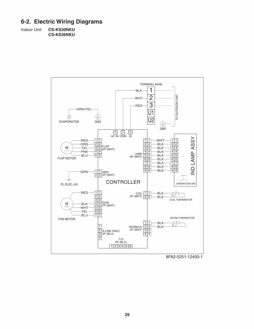
6-2. Electric Wiring DiagramsIndoor Unit CS-KS30NKU CS-KS36NKU
29
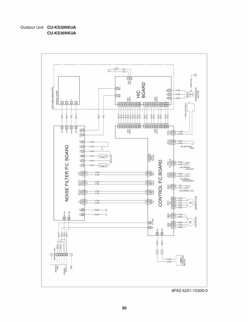
Outdoor Unit CU-KS30NKUA CU-KS36NKUA
8FA2-5251-15300-0
CO
NT
RO
L P
.C.B
OA
RD
NO
ISE
FIL
TE
R P
.C. B
OA
RD
HIC
BO
AR
D
+
+
HIC
-
W
TS
R
VU
+-
+H
IC+
+L1+L2
+D
C-
TH
01(Y
EL)
TH
1
++
M 3
CO
MP
RE
SS
OR
M
OT
OR
BLU
WHT
RED
1 2 3 10
1 2 34 5
4 56 7
6 78 9
8 9 10
1 2
1 2
3 10
1 2 34 5
4 56 7
6 78 9
8 9 10
HIC
1(W
HT
)C
N01
(WH
T)
WH
TB
LK
BL
KB
LK
BL
KB
LK
BL
KB
LK
BL
KB
LK
1 2 3 11
1 2 34 5
4 56 7
6 78 9
8 9 11
1 2 3 11
1 2 34 5
4 56 7
6 78 9
8 9 11
HIC
2(W
HT
)C
N02
(WH
T)
BL
KB
LK
BL
KB
LK
BL
KB
LK
1010
1010
BL
KB
LK
4 45 5
1 12 2
3
12
3
33 3
1 12 2
3 31 1
(WH
T)
MV
(WH
T)
TES
T/M
V
MA
GN
ETI
C C
OIL
HE
AT
SIN
K (
RA
DIA
TO
R)
BR
IDG
E D
IOD
E
ORGREDYELBLKGRY
2 21 1(B
LK)
CO
IL YELYEL
COIL THERMISTOR
2 21 1(G
RN
)P
RY BLKWHT2 2
1 1
3 31 1(W
HT
)D
CO
UT
BLKWHT
3 31 1
3 31 1(O
RG
)A
CO
UT
BLKWHT
3 31 1
2 21 1(B
RN
)
(GR
N)
(WH
T)
(OR
G)
(BR
N)
CT
PR
YD
CIN
AC
INC
TWHTWHT
2 21 1
IND
OO
RU
NIT
PO
WE
R
S
UP
PLY
GN
D
TE
RM
INA
L (5
P)
FM
2(R
ED
)
REDBLU
BRNWHTORG
FM
1(R
ED
)
FAN
MO
TOR
RE
AC
TO
R
C1
wE2
wE1
1 2 3 4 5
YELYEL
BL
U
wC
H2
CR
AN
KC
AS
EH
EA
TE
R
WH
T
WHTWHT
++
+D
C+
YE
L
GR
Y
YE
L
++
AC
2w
AC
IN2
wA
C IN
1W
HT
++
AC
1B
LK
MM
2 21 1(W
HT
)C
OM
P
BLKBLK
COMPRESSOR THERMISTOR
2 21 1(Y
EL)
OU
TD
OO
R
BLKBLK
OUTDOOR THERMISTOR
GR
N/Y
EL
2 21 1(B
LK)
HP
-SW
REDRED
HIGH PRESSURE SW
2 21 1(R
ED
)O
LR WHTWHT
OV
ER
LO
AD
RE
LAY
BLK
WHT
+L3+L4
BLK
WHT
+C1
+C2
+H
IC+
+H
IC-
BLK
WHT
11
w
w
CH
1
SI
wS
-CO
M
WH
T1
1
BL
K
WH
TR
ED
WH
T
BL
KW
HT
GRN
GRN
30
Emergency operation
Emergency operation is available when the remote controller malfunctions, has been lost, or otherwise cannot be used.
• The set temperature is 4°F(2°C) below the detected room temperature in the case of cooling operation.
(GREEN) (Lamp Off)COOL STOP
To operate the system, press the OPERATION button, which is also used as the receiver, below the unit display. Each time this button is pressed, the OPERATION lamp changes color to indicate the type of operation. Select the desired type of operation.
7. FUNCTIONS7-1. Operation Functions
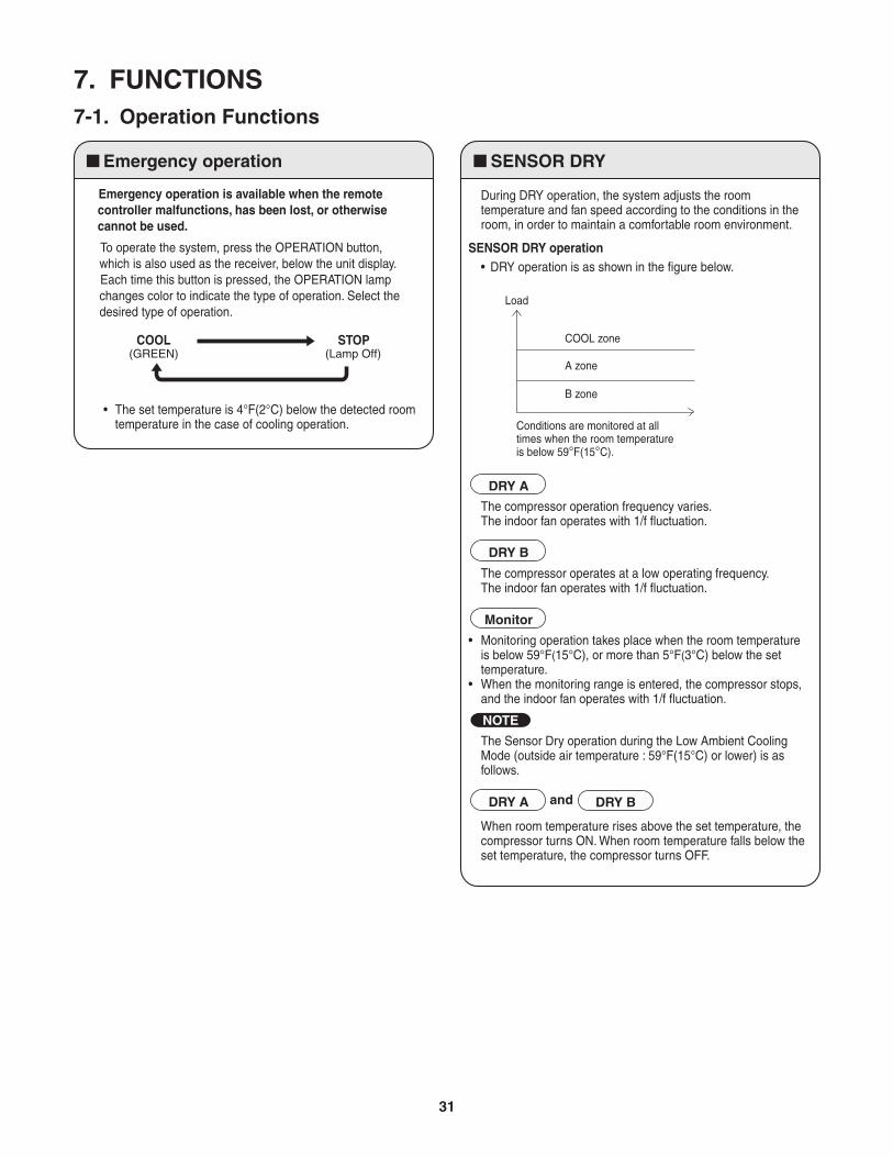
SENSOR DRY
During DRY operation, the system adjusts the room temperature and fan speed according to the conditions in the room, in order to maintain a comfortable room environment.
SENSOR DRY operation • DRY operation is as shown in the figure below.
The compressor operation frequency varies. The indoor fan operates with 1/f fluctuation.
The compressor operates at a low operating frequency. The indoor fan operates with 1/f fluctuation.
When room temperature rises above the set temperature, the compressor turns ON. When room temperature falls below the set temperature, the compressor turns OFF.
The Sensor Dry operation during the Low Ambient Cooling Mode (outside air temperature : 59°F(15°C) or lower) is as follows.
• Monitoring operation takes place when the room temperature is below 59°F(15°C), or more than 5°F(3°C) below the set temperature.
• When the monitoring range is entered, the compressor stops, and the indoor fan operates with 1/f fluctuation.
DRY A
DRY B
DRY A DRY B
Monitor
Conditions are monitored at all times when the room temperature is below 59°F(15°C).
Load
COOL zone
A zone
B zone
NOTE
and
31
HIGH POWER NIGHT SETBACK
Lamp colors
Timer backup
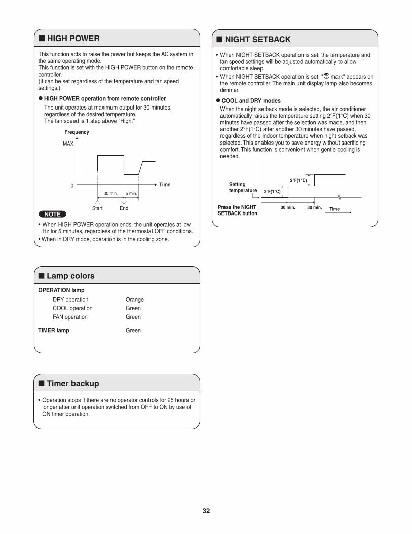
This function acts to raise the power but keeps the AC system in the same operating mode.This function is set with the HIGH POWER button on the remote controller.(It can be set regardless of the temperature and fan speed settings.)
HIGH POWER operation from remote controller The unit operates at maximum output for 30 minutes,
regardless of the desired temperature. The fan speed is 1 step above "High."
OPERATION lamp
• When HIGH POWER operation ends, the unit operates at low Hz for 5 minutes, regardless of the thermostat OFF conditions.
• When in DRY mode, operation is in the cooling zone.
• Operation stops if there are no operator controls for 25 hours or longer after unit operation switched from OFF to ON by use of ON timer operation.
Frequency
MAX
0
Start End
Time
30 min. 5 min.
Settingtemperature
Press the NIGHTSETBACK button
• When NIGHT SETBACK operation is set, the temperature and fan speed settings will be adjusted automatically to allow comfortable sleep.
• When NIGHT SETBACK operation is set, " mark" appears on the remote controller. The main unit display lamp also becomes dimmer.
COOL and DRY modesWhen the night setback mode is selected, the air conditioner automatically raises the temperature setting 2°F(1°C) when 30 minutes have passed after the selection was made, and then another 2°F(1°C) after another 30 minutes have passed, regardless of the indoor temperature when night setback was selected. This enables you to save energy without sacrificing comfort. This function is convenient when gentle cooling is needed.
TIMER lamp Green
DRY operation OrangeCOOL operation GreenFAN operation Green
NOTE30 min. 30 min. Time
2°F(1°C)
2°F(1°C)
32
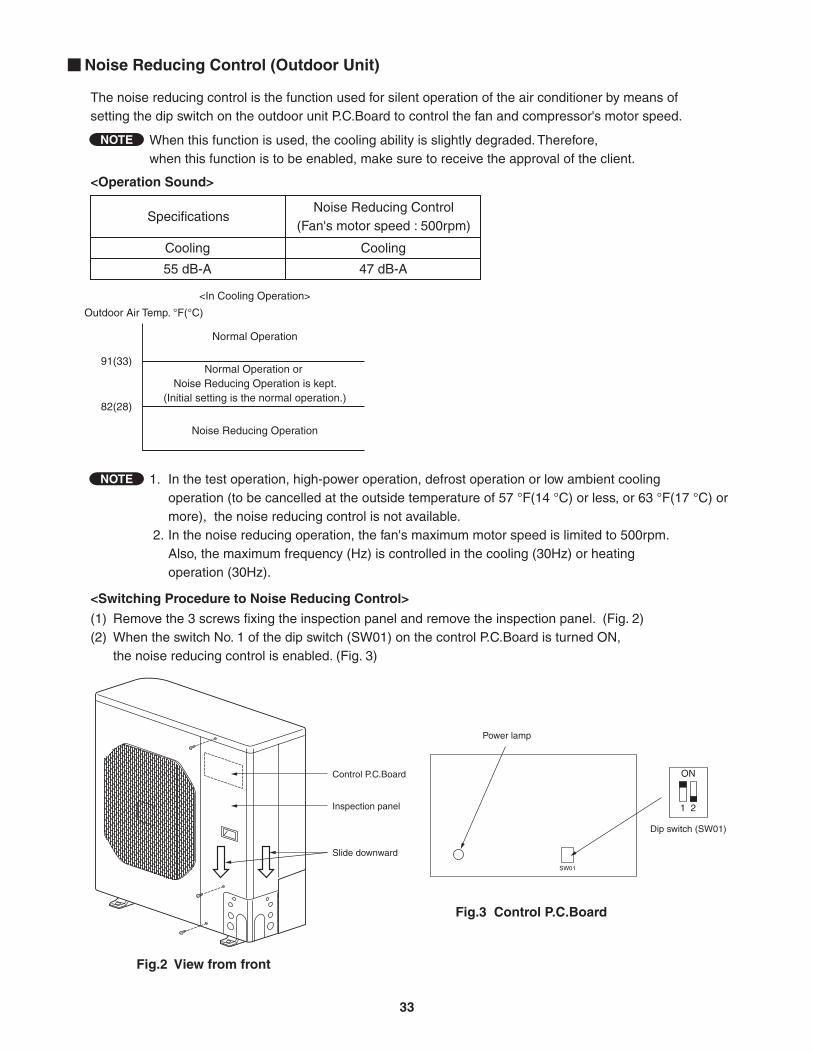
The noise reducing control is the function used for silent operation of the air conditioner by means of setting the dip switch on the outdoor unit P.C.Board to control the fan and compressor's motor speed.
<Operation Sound>
<Switching Procedure to Noise Reducing Control>
(1) Remove the 3 screws fixing the inspection panel and remove the inspection panel. (Fig. 2)(2) When the switch No. 1 of the dip switch (SW01) on the control P.C.Board is turned ON, the noise reducing control is enabled. (Fig. 3)
When this function is used, the cooling ability is slightly degraded. Therefore, when this function is to be enabled, make sure to receive the approval of the client.
1. In the test operation, high-power operation, defrost operation or low ambient cooling operation (to be cancelled at the outside temperature of 57 °F(14 °C) or less, or 63 °F(17 °C) or more), the noise reducing control is not available. 2. In the noise reducing operation, the fan's maximum motor speed is limited to 500rpm. Also, the maximum frequency (Hz) is controlled in the cooling (30Hz) or heating operation (30Hz).
<In Cooling Operation>
Specifications
Cooling Cooling
55 dB-A 47 dB-A
Noise Reducing Control(Fan's motor speed : 500rpm)
Normal Operation
Normal Operation or Noise Reducing Operation is kept.
(Initial setting is the normal operation.)
Noise Reducing Operation
Outdoor Air Temp. °F(°C)
91(33)
82(28)
Noise Reducing Control (Outdoor Unit)
Fig.2 View from front
Fig.3 Control P.C.Board
SW01
Dip switch (SW01)
ON
1 2
Power lamp
NOTE
NOTE
Control P.C.Board
Inspection panel
Slide downward
33
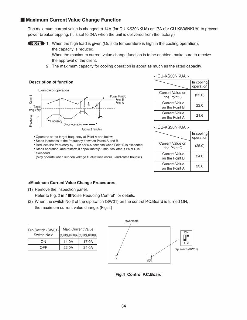
The maximum current value is changed to 14A (for CU-KS30NKUA) or 17A (for CU-KS36NKUA) to prevent power breaker tripping. (It is set to 24A when the unit is delivered from the factory.)
<Maximum Current Value Change Procedure>
(1) Remove the inspection panel.
Refer to Fig. 2 in " Noise Reducing Control" for details.
(2) When the switch No.2 of the dip switch (SW01) on the control P.C.Board is turned ON,
the maximum current value change. (Fig. 4)
Maximum Current Value Change Function
< CU-KS30NKUA >
Current Value on the Point C
Current Valueon the Point B
Current Valueon the Point A
In coolingoperation
< CU-KS36NKUA >
Current Value on the Point C
Current Valueon the Point B
Current Valueon the Point A
(25.0)
22.0
21.6
(25.0)
24.0
23.6
In coolingoperation
Dip Switch (SW01)Switch No.2
ON
OFF
Max. Current Value
CU-KS30NKUA CU-KS36NKUA
14.0A 17.0A
22.0A 24.0A
1. When the high load is given (Outside temperature is high in the cooling operation), the capacity is reduced. When the maximum current value change function is to be enabled, make sure to receive the approval of the client.2. The maximum capacity for cooling operation is about as much as the rated capacity.
NOTE
Description of function
Example of operation
Frequency
Freq
uenc
yCu
rrent
Stops operation
Approx.3 minutes
Power Point CPoint BPoint A
Targetfrequency
Operates at the target frequency at Point A and below.Stops increases to the frequency between Points A and B.Reduces the frequency by 1 Hz per 0.5 seconds when Point B is exceeded.Stops operation, and restarts it appoximately 5 minutes later, if Point C is exceeded.(May operate when sudden voltage fluctuations occur. Indicates trouble.)
••••
Fig.4 Control P.C.Board
SW01
Dip switch (SW01)
ON
1 2
Power lamp
34
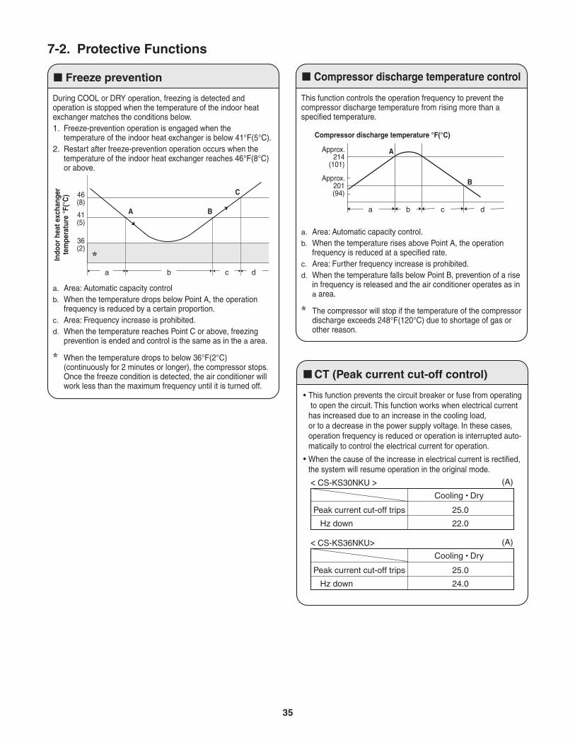
Compressor discharge temperature controlFreeze prevention
During COOL or DRY operation, freezing is detected and operation is stopped when the temperature of the indoor heat exchanger matches the conditions below.1. Freeze-prevention operation is engaged when the
temperature of the indoor heat exchanger is below 41°F(5°C).2. Restart after freeze-prevention operation occurs when the
temperature of the indoor heat exchanger reaches 46°F(8°C) or above.
a. Area: Automatic capacity controlb. When the temperature drops below Point A, the operation
frequency is reduced by a certain proportion.c. Area: Frequency increase is prohibited.d. When the temperature reaches Point C or above, freezing
prevention is ended and control is the same as in the a area.
* When the temperature drops to below 36°F(2°C) (continuously for 2 minutes or longer), the compressor stops.Once the freeze condition is detected, the air conditioner will work less than the maximum frequency until it is turned off.
A
*
B
C
a b c d
Indo
or h
eat e
xcha
nger
tem
pera
ture
°F(
°C)
36(2)
41(5)
46(8)
This function controls the operation frequency to prevent the compressor discharge temperature from rising more than a specified temperature.
a. Area: Automatic capacity control.b. When the temperature rises above Point A, the operation
frequency is reduced at a specified rate.c. Area: Further frequency increase is prohibited.d. When the temperature falls below Point B, prevention of a rise
in frequency is released and the air conditioner operates as in a area.
* The compressor will stop if the temperature of the compressor discharge exceeds 248°F(120°C) due to shortage of gas or other reason.
Approx.214
(101)
A
B
a b c d
Compressor discharge temperature °F(°C)
Approx.201(94)
7-2. Protective Functions
This function prevents the circuit breaker or fuse from operating to open the circuit. This function works when electrical current has increased due to an increase in the cooling load, or to a decrease in the power supply voltage. In these cases, operation frequency is reduced or operation is interrupted auto-matically to control the electrical current for operation.
When the cause of the increase in electrical current is rectified, the system will resume operation in the original mode.
Cooling Dry
Peak current cut-off trips 25.0
Hz down 22.0
(A)
CT (Peak current cut-off control)
•
•
< CS-KS30NKU >
Cooling Dry
Peak current cut-off trips 25.0
Hz down 24.0
(A)< CS-KS36NKU>
35
8. TROUBLESHOOTING (BEFORE CALLING FOR SERVICE)
8-1. Precautions before Performing Inspection or Repair
NOTE
After checking the self-diagnostics monitor, turn the power OFF before starting inspection or repair.
High-capacity electrolytic capacitors are used inside the outdoor unit controller (inverter). They retain an electrical charge (charging voltage DC 310V) even after the power is turned OFF, and some time is required for the charge to dissipate. Be careful not to touch any electrified parts before the controller LED (red) turns OFF.
If the outdoor controller is normal, approximately 30 seconds will be required for the charge to dissipate. However, allow at least 5 minutes for the charge to dissipate if there is thought to be any trouble with the outdoor controller.
1: If the operation lamp blinks every 0.5 seconds immediately when the power is turned ON, there is an external ROM (OTP data) failure on the indoor circuit board, or a ROM socket insertion problem, or the ROM has not been installed.
2: The failure mode is stored in memory even when the power is not ON. Follow the procedure below to perform diagnostics.
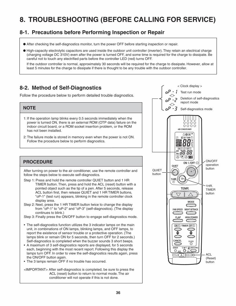
8-2. Method of Self-DiagnosticsFollow the procedure below to perform detailed trouble diagnostics.
< Clock display >
Test run mode
Self-diagnostics mode
Deletion of self-diagnostics report mode
PROCEDURE
Step 1: Press and hold the remote controller QUIET button and 1 HR TIMER button. Then, press and hold the ACL (reset) button with a pointed object such as the tip of a pen. After 5 seconds, release ACL button first, then release QUIET and 1 HR TIMER buttons, "oP-1" (test run) appears, blinking in the remote controller clock display area.
Step 2: Next, press the 1 HR TIMER button twice to change the display from "oP-1" to "oP-2" and "oP-3" (self-diagnostics). (The display continues to blink.)
Step 3: Finally press the ON/OFF button to engage self-diagnostics mode.
• The self-diagnostics function utilizes the 3 indicator lamps on the main unit, in combinations of ON lamps, blinking lamps, and OFF lamps, to report the existence of sensor trouble or a protective operation. (The lamps blink or remain ON for 5 seconds, then turn OFF for 2 seconds.) Self-diagnostics is completed when the buzzer sounds 3 short beeps.
• A maximum of 3 self-diagnostics reports are displayed, for 5 seconds each, beginning with the most recent report. Following this display the lamps turn OFF. In order to view the self-diagnostics results again, press the ON/OFF button again.
• The 3 lamps remain OFF if no trouble has occurred.
<IMPORTANT> After self-diagnostics is completed, be sure to press the ACL (reset) button to return to normal mode. The air conditioner will not operate if this is not done.
After turning on power to the air conditioner, use the remote controller and follow the steps below to execute self-diagnostics.
1HR.TIMERbutton
ON/OFFoperationbutton
ACL(Reset)button
QUIETbutton
36
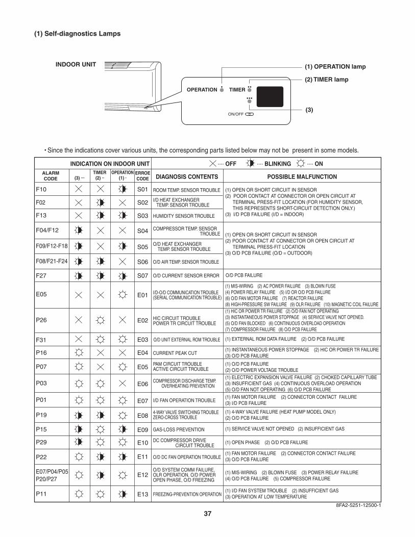
Since the indications cover various units, the corresponding parts listed below may not be present in some models.
(1) OPERATION lamp
(2) TIMER lamp
(3)
OPERATION TIMER
ON/OFF
INDOOR UNIT
(1) Self-diagnostics Lamps
INDICATION ON INDOOR UNIT .... OFF
DIAGNOSIS CONTENTS POSSIBLE MALFUNCTION
ROOM TEMP. SENSOR TROUBLE
I/D HEAT EXCHANGER TEMP. SENSOR TROUBLE
HUMIDITY SENSOR TROUBLE
COMPRESSOR TEMP. SENSOR TROUBLE
O/D HEAT EXCHANGER TEMP. SENSOR TROUBLE
O/D AIR TEMP. SENSOR TROUBLE
I/D-O/D COMMUNICATION TROUBLE (SERIAL COMMUNICATION TROUBLE)
O/D UNIT EXTERNAL ROM TROUBLE
CURRENT PEAK CUT
HIC CIRCUIT TROUBLEPOWER TR CIRCUIT TROUBLE
PAM CIRCUIT TROUBLEACTIVE CIRCUIT TROUBLE
O/D SYSTEM COMM FAILURE,OLR OPERATION, O/D POWEROPEN PHASE, O/D FREEZING
COMPRESSOR DISCHARGE TEMP. OVERHEATING PREVENTION
I/D FAN OPERATION TROUBLE
GAS-LOSS PREVENTION
DC COMPRESSOR DRIVE CIRCUIT TROUBLE
O/D DC FAN OPERATION TROUBLE
FREEZING-PREVENTION OPERATION
4-WAY VALVE SWITCHING TROUBLEZERO-CROSS TROUBLE
O/D CURRENT SENSOR ERROR
.... BLINKING .... ONTIMER OPERATION
(3) ... (2) .. (1) .
(1) OPEN OR SHORT CIRCUIT IN SENSOR(2) POOR CONTACT AT CONNECTOR OR OPEN CIRCUIT AT TERMINAL PRESS-FIT LOCATION (FOR HUMIDITY SENSOR, THIS REPRESENTS SHORT-CIRCUIT DETECTION ONLY.)(3) I/D PCB FAILURE (I/D = INDOOR)
(1) OPEN OR SHORT CIRCUIT IN SENSOR(2) POOR CONTACT AT CONNECTOR OR OPEN CIRCUIT AT TERMINAL PRESS-FIT LOCATION(3) O/D PCB FAILURE (O/D = OUTDOOR)
O/D PCB FAILURE
(1) MIS-WIRING (2) AC POWER FAILURE (3) BLOWN FUSE(4) POWER RELAY FAILURE (5) I/D OR O/D PCB FAILURE(6) O/D FAN MOTOR FAILURE (7) REACTOR FAILURE(8) HIGH-PRESSURE SW FAILURE (9) OLR FAILURE (10) MAGNETIC COIL FAILURE(1) HIC OR POWER TR FAILURE (2) O/D FAN NOT OPERATING(3) INSTANTANEOUS POWER STOPPAGE (4) SERVICE VALVE NOT OPENED. (5) O/D FAN BLOCKED (6) CONTINUOUS OVERLOAD OPERATION (7) COMPRESSOR FAILURE (8) O/D PCB FAILURE
(1) EXTERNAL ROM DATA FAILURE (2) O/D PCB FAILURE
(1) INSTANTANEOUS POWER STOPPAGE (2) HIC OR POWER TR FAILURE (3) O/D PCB FAILURE
(1) O/D PCB FAILURE(2) O/D POWER VOLTAGE TROUBLE(1) ELECTRIC EXPANSION VALVE FAILURE (2) CHOKED CAPILLARY TUBE(3) INSUFFICIENT GAS (4) CONTINUOUS OVERLOAD OPERATION(5) O/D FAN NOT OPERATING (6) O/D PCB FAILURE
(1) FAN MOTOR FAILURE (2) CONNECTOR CONTACT FAILURE(3) I/D PCB FAILURE
(1) 4-WAY VALVE FAILURE (HEAT PUMP MODEL ONLY)(2) O/D PCB FAILURE
(1) SERVICE VALVE NOT OPENED (2) INSUFFICIENT GAS
(1) OPEN PHASE (2) O/D PCB FAILURE
(1) FAN MOTOR FAILURE (2) CONNECTOR CONTACT FAILURE(3) O/D PCB FAILURE
(1) MIS-WIRING (2) BLOWN FUSE (3) POWER RELAY FAILURE(4) O/D PCB FAILURE (5) COMPRESSOR FAILURE
(1) I/D FAN SYSTEM TROUBLE (2) INSUFFICIENT GAS(3) OPERATION AT LOW TEMPERATURE
8FA2-5251-12500-1
S01F10
F02
F13
F04/F12
F09/F12-F18
F08/F21-F24
F27
E05
P26
F31
P16
P07
P03
P01
P19
P15
P29
P22
E07/P04/P05P20/P27
P11
S02
S03
S04
S05
S06
S07
E01
E02
E03
E04
E05
E06
E07
E08
E09
E10
E11
E12
E13
ERROECODE
ALARMCODE
37
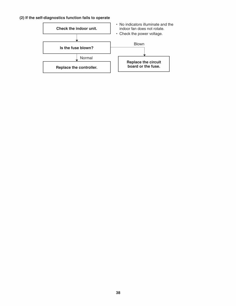
(2) If the self-diagnostics function fails to operate
Check the indoor unit.
Is the fuse blown?
Replace the controller.Replace the circuitboard or the fuse.
No indicators illuminate and the indoor fan does not rotate.Check the power voltage.
Normal
Blown
38
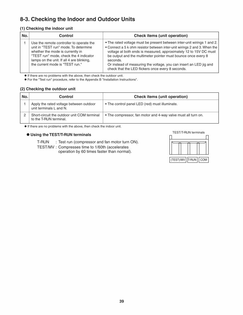
8-3. Checking the Indoor and Outdoor Units
(1) Checking the indoor unit
(2) Checking the outdoor unit
Using the TEST/T-RUN terminals
ControlNo. Check items (unit operation)
T-RUN : Test run (compressor and fan motor turn ON).TEST/MV : Compresses time to 1/60th (accelerates
operation by 60 times faster than normal).
Use the remote controller to operate theunit in "TEST run" mode. To determinewhether the mode is currently in"TEST run" mode, check the 4 indicator lamps on the unit. If all 4 are blinking,the current mode is "TEST run."
If there are no problems with the above, then check the outdoor unit.
1 The rated voltage must be present between inter-unit wirings 1 and 2.Connect a 5 k ohm resistor between inter-unit wirings 2 and 3. When the voltage at both ends is measured, approximately 12 to 15V DC must be output and the multimeter pointer must bounce once every 8 seconds.Or instead of measuring the voltage, you can insert an LED jig and check that the LED flickers once every 8 seconds.
••
ControlNo. Check items (unit operation)
Apply the rated voltage between outdoor unit terminals L and N.
If there are no problems with the above, then check the indoor unit.
1 The control panel LED (red) must illuminate.
Short-circuit the outdoor unit COM terminal to the T-RUN terminal.
2 The compressor, fan motor and 4-way valve must all turn on.
•
•
TEST/T-RUN terminals
(TEST)/MV T-RUN COM
For the "Test run" procedure, refer to the Appendix B "Installation Instructions".
39
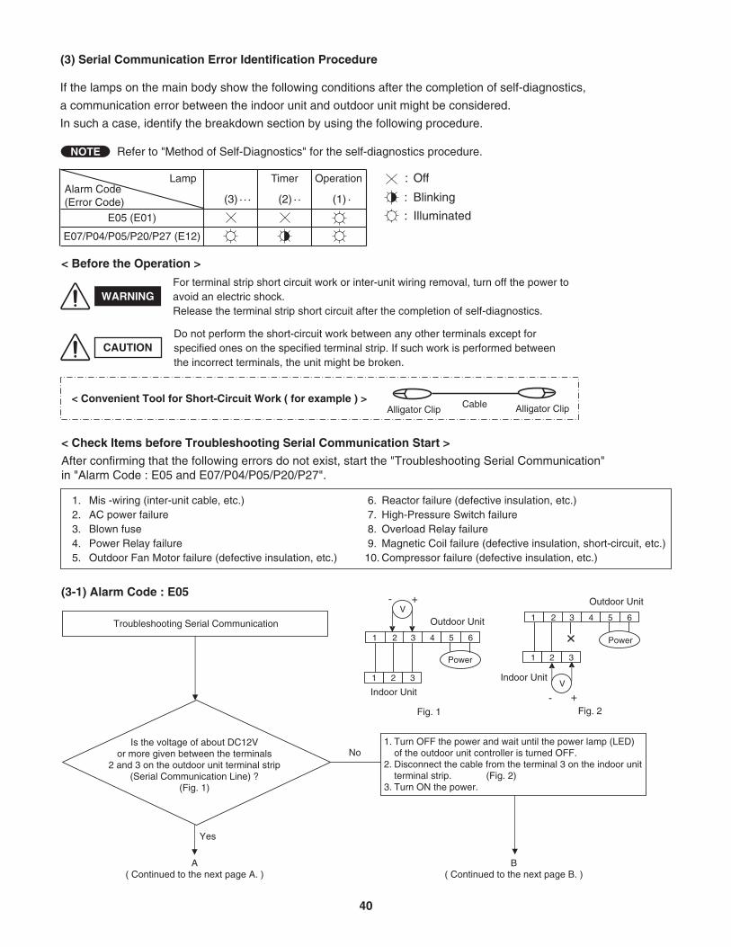
(3) Serial Communication Error Identification Procedure
Refer to "Method of Self-Diagnostics" for the self-diagnostics procedure.
(3-1) Alarm Code : E05
< Before the Operation >
If the lamps on the main body show the following conditions after the completion of self-diagnostics,
a communication error between the indoor unit and outdoor unit might be considered.
In such a case, identify the breakdown section by using the following procedure.
Troubleshooting Serial Communication
Is the voltage of about DC12Vor more given between the terminals
2 and 3 on the outdoor unit terminal strip(Serial Communication Line) ?
(Fig. 1)
No
Yes
1. Turn OFF the power and wait until the power lamp (LED)of the outdoor unit controller is turned OFF.
2. Disconnect the cable from the terminal 3 on the indoor unitterminal strip. (Fig. 2)
3. Turn ON the power.
< Convenient Tool for Short-Circuit Work ( for example ) >Alligator ClipAlligator Clip Cable
A( Continued to the next page A. )
B( Continued to the next page B. )
For terminal strip short circuit work or inter-unit wiring removal, turn off the power toavoid an electric shock.Release the terminal strip short circuit after the completion of self-diagnostics.
Do not perform the short-circuit work between any other terminals except forspecified ones on the specified terminal strip. If such work is performed betweenthe incorrect terminals, the unit might be broken.
Fig. 1
Outdoor Unit
Power
1 2 43 5 6
1 2 3
V+-
Indoor Unit
Outdoor Unit
1 2 43 5 6
1 2 3
V
+-
Power
Indoor Unit
Fig. 2
NOTE
Lamp Timer Operation : Off
: BlinkingAlarm Code(Error Code) (3) · · · (2) · · (1) ·
: IlluminatedE05 (E01)
E07/P04/P05/P20/P27 (E12)
CAUTION
WARNING
< Check Items before Troubleshooting Serial Communication Start >
After confirming that the following errors do not exist, start the "Troubleshooting Serial Communication"in "Alarm Code : E05 and E07/P04/P05/P20/P27".
1. Mis -wiring (inter-unit cable, etc.)2. AC power failure3. Blown fuse4. Power Relay failure5. Outdoor Fan Motor failure (defective insulation, etc.)
6. Reactor failure (defective insulation, etc.) 7. High-Pressure Switch failure 8. Overload Relay failure 9. Magnetic Coil failure (defective insulation, short-circuit, etc.)10. Compressor failure (defective insulation, etc.)
40
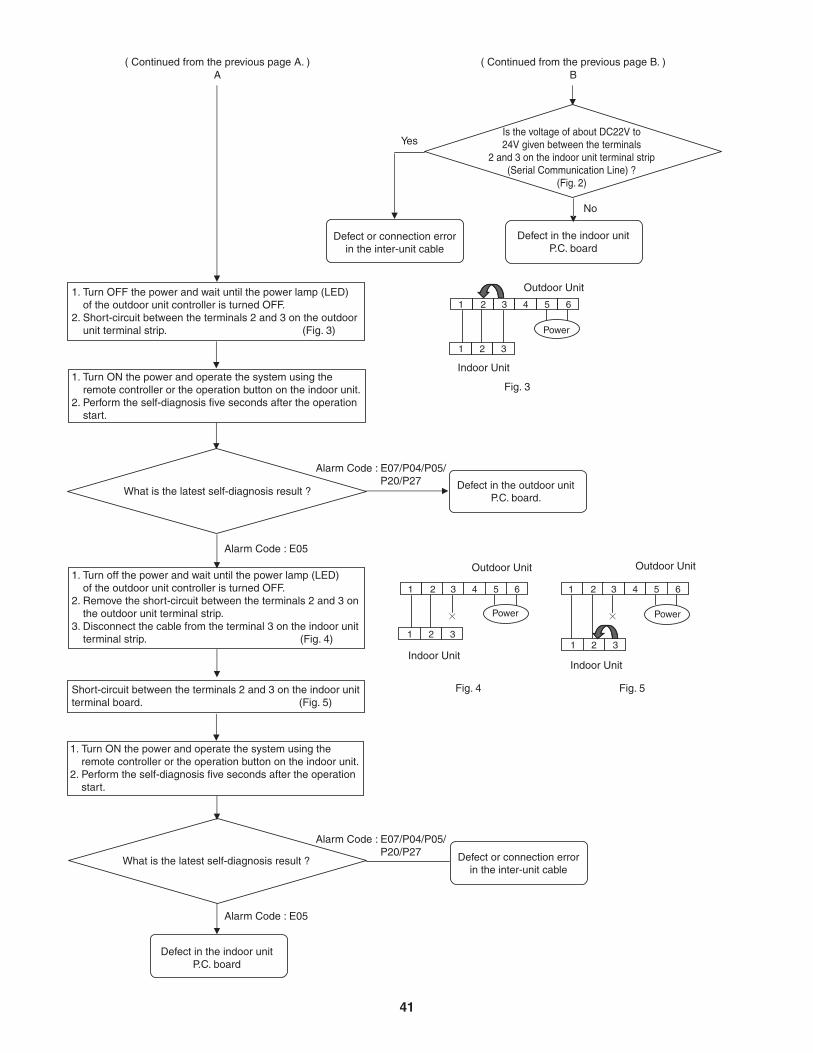
What is the latest self-diagnosis result ?
Alarm Code : E07/P04/P05/P20/P27
Alarm Code : E07/P04/P05/P20/P27
Defect in the outdoor unitP.C. board.
Alarm Code : E05
Defect or connection errorin the inter-unit cable
Defect in the indoor unitP.C. board
( Continued from the previous page A. )A
( Continued from the previous page B. )B
1 2 43 5 6
1 2 3
Outdoor Unit
Power
Fig. 3
Indoor Unit
1 2 43 5 6
1 2 3
Outdoor Unit
Power
Fig. 4
Indoor Unit
1 2 43 5 6
1 2 3
Outdoor Unit
Power
Fig. 5
Indoor Unit
Alarm Code : E05
1. Turn OFF the power and wait until the power lamp (LED) of the outdoor unit controller is turned OFF.2. Short-circuit between the terminals 2 and 3 on the outdoor unit terminal strip. (Fig. 3)
1. Turn ON the power and operate the system using the remote controller or the operation button on the indoor unit.2. Perform the self-diagnosis five seconds after the operation start.
1. Turn off the power and wait until the power lamp (LED) of the outdoor unit controller is turned OFF.2. Remove the short-circuit between the terminals 2 and 3 on the outdoor unit terminal strip.3. Disconnect the cable from the terminal 3 on the indoor unit terminal strip. (Fig. 4)
Short-circuit between the terminals 2 and 3 on the indoor unitterminal board. (Fig. 5)
1. Turn ON the power and operate the system using the remote controller or the operation button on the indoor unit.2. Perform the self-diagnosis five seconds after the operation start.
What is the latest self-diagnosis result ?
Defect in the indoor unitP.C. board
Is the voltage of about DC22V to24V given between the terminals
2 and 3 on the indoor unit terminal strip(Serial Communication Line) ?
(Fig. 2)
No
Defect or connection errorin the inter-unit cable
Yes
41
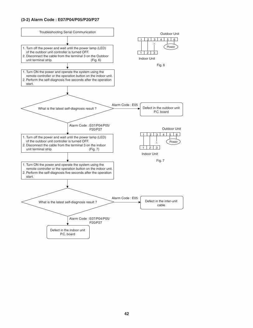
(3-2) Alarm Code : E07/P04/P05/P20/P27
Troubleshooting Serial Communication
1. Turn off the power and wait until the power lamp (LED) of the outdoor unit controller is turned OFF.2. Disconnect the cable from the terminal 3 on the indoor unit terminal strip. (Fig. 7)
Defect in the indoor unitP.C. board
Defect in the outdoor unitP.C. board
1. Turn ON the power and operate the system using the remote controller or the operation button on the indoor unit.2. Perform the self-diagnosis five seconds after the operation start.
1. Turn off the power and wait until the power lamp (LED) of the outdoor unit controller is turned OFF.2. Disconnect the cable from the terminal 3 on the Outdoor unit terminal strip. (Fig. 6)
Defect in the inter-unitcable
1. Turn ON the power and operate the system using the remote controller or the operation button on the indoor unit.2. Perform the self-diagnosis five seconds after the operation start.
What is the latest self-diagnosis result ?
What is the latest self-diagnosis result ?
1 2 43 5 6
1 2 3
Outdoor Unit
Fig. 6
Power
Indoor Unit
1 2 43 5 6
1 2 3
Power
Fig. 7
Outdoor Unit
Indoor Unit
Alarm Code : E07/P04/P05/P20/P27
Alarm Code : E05
Alarm Code : E07/P04/P05/P20/P27
Alarm Code : E05
42
[Trouble symptom 3] Motor rotates for some time (several seconds), but then quickly stops, when the indoor unit operates.(There is trouble in the system that provides feedback of motor rotation speed from the motor to the indoor unit controller.)
[Trouble symptom 4] Fan motor rotation speed does not change during indoor unit operation.
[Trouble symptom 5] Fan motor rotation speed varies excessively during indoor unit operation.
(Remedy for symptom 3 to 5)It is not possible to identify whether the trouble is indoor unit controller trouble or motor trouble. Therefore, first replace the indoor unit controller, then (if necessary) replace the DC motor.
8-4. Trouble Diagnosis of Fan Motor8-4-1. Indoor Fan Motor
This indoor DC fan motor contains an internal control PCB. Therefore, it is not possible to measure the coil resistance, and the following procedure should be used to check the motor.To perform diagnosis, operate the unit in cooling mode with indoor fan speed "High". Next, make sure that the indoor unit receive the signals from the remote controller when the ON/OFF operation button is pressed.
[Trouble symptom 1] The fan does not stop when the unit stops. Indoor unit controller trouble.
[Trouble symptom 2] The fan motor does not rotate when the unit is operating.(Diagnostic procedure)
* Disconnect the motor connectors and measure the voltage at the DC motor connectors on the indoor unit controller (3 locations).
(Diagnostic results)All of the above measured values are normal. Fan motor trouble (Replace the motor.)Any one of the above measured values is not normal. Indoor unit controller trouble (Replace the controller .)
(Reference) DC motor connector pin arrangement Pin 1: Vm (red) Pin 2: Not used Pin 3: Not used Pin 4: Gnd (black) Pin 5: Vcc (white) Pin 6: Vs (yellow) Pin 7: PG (blue)
Important: (A) Turn OFF the power before connecting or disconnecting the motor connectors.(B) When performing voltage measurement at the indoor controller connector for (3) in the table
below, the DC motor will trip and voltage output will stop approximately 1 minute after operation is started. For this reason, to measure the voltage again, turn OFF the unit once using the remote controller, and then start the air conditioner again.
(1) Vm-Gnd: Between pin 1 and pin 4(2) Vcc-Gnd: Between pin 5 and pin 4(3) Vs-Gnd: Between pin 6 and pin 4
Measurement locationDC 280 V +/-10%DC 15 V +/-10%Fluctuation between DC 1.63 to 6.23 V
Normal value
43
8-4-2. Outdoor Fan Motor
This outdoor DC fan motor contains an internal control PCB. Therefore, it is not possible to measure the coil resistance, and the following procedure should be used to check the motor.Perform the trouble diagnosis by Test Run mode described on Installation Instructions of indoor unit.
[Trouble symptom 1] The fan does not stop when the outdoor unit stops. Outdoor unit controller trouble
[Trouble symptom 2] The fan motor does not rotate when the outdoor unit is operating.(Diagnostic procedure)
* Disconnect the motor connectors and measure the voltage at the DC motor connectors on the outdoor unit controller (3 locations).
(Diagnostic results)All of the above measured values are normal. Fan motor trouble (Replace the motor.)Any one of the above measured values is not normal. Outdoor unit controller trouble
(Replace the controller .)(Reference) DC motor connector pin arrangement
[Trouble symptom 3] Motor rotates for some time (several seconds), but then quickly stops, when the outdoor unit operates.(There is trouble in the system that provides feedback of motor rotation speed from the motor to the outdoor unit controller.)
[Trouble symptom 4] Fan motor rotation speed does not change during outdoor unit operation.
[Trouble symptom 5] Fan motor rotation speed varies excessively during outdoor unit operation.
(Remedy for symptom 3 to 5)It is not possible to identify whether the trouble is outdoor unit controller trouble or motor trouble. Therefore, first replace the outdoor unit controller, then (if necessary) replace the DC motor.
Important: (A) Turn OFF the power before connecting or disconnecting the motor connectors.(B) When performing voltage measurement at the outdoor controller connector for (3) in the table
below, the DC motor will trip and voltage output will stop approximately 10 seconds after operation is started. For this reason, to measure the voltage again, first turn OFF the outdoor unit power, then, measure the voltage in Test Run mode.
Pin 1: Vm (red)Pin 2: Not usedPin 3: Gnd (blue)Pin 1: Vcc (brown)Pin 2: PG (white)Pin 3: Vsp (orange)
Pin
FM1
FM2
Connector No.
(1) Vm-Gnd : Between pin 1 and pin 3 of FM1(2) Vcc-Gnd : Between pin 1 of FM2 and pin3 of FM1(3) Vs-Gnd : Between pin 3 of FM2 and pin3 of FM1
Measurement locationDC 280V +/- 10%DC 15V +/- 10%Fluctuation between DC 1.8V to 5.7V
Normal value
44
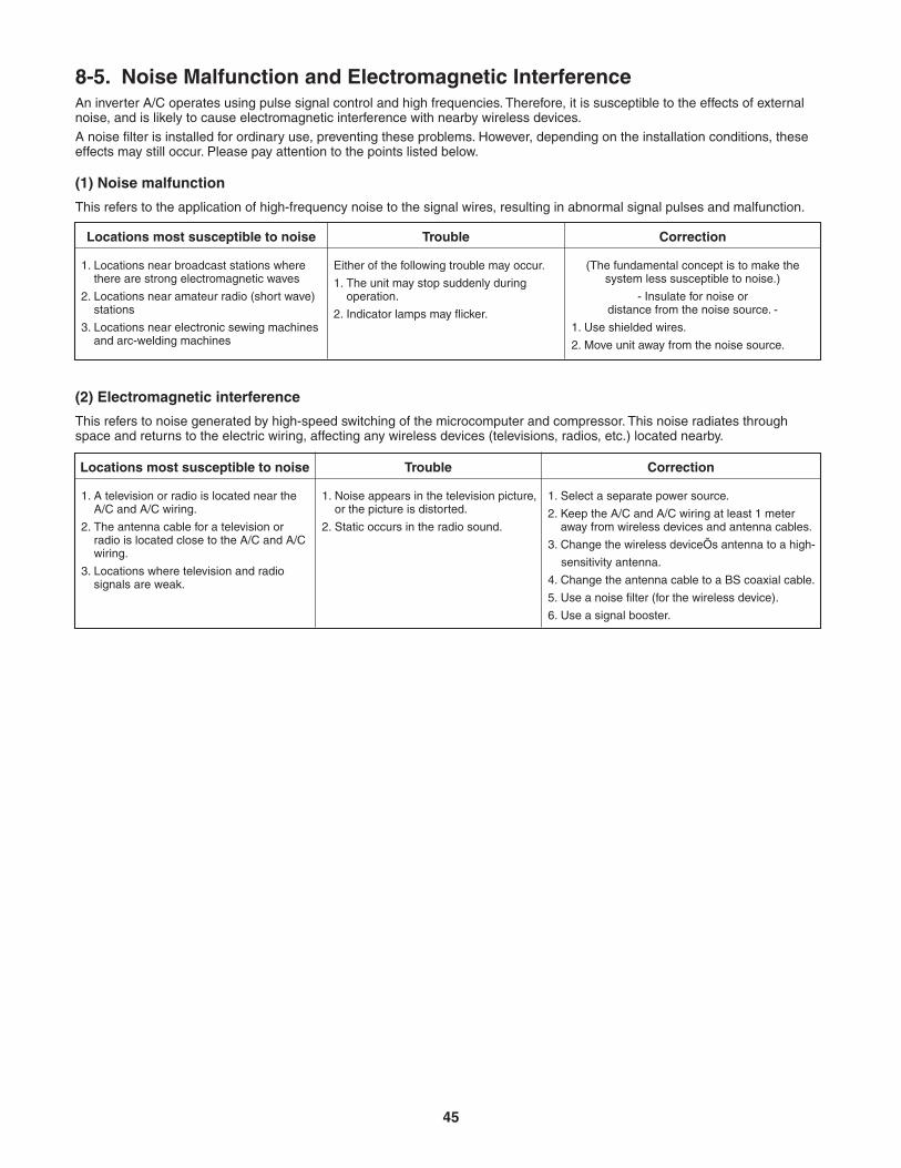
8-5. Noise Malfunction and Electromagnetic InterferenceAn inverter A/C operates using pulse signal control and high frequencies. Therefore, it is susceptible to the effects of external noise, and is likely to cause electromagnetic interference with nearby wireless devices. A noise filter is installed for ordinary use, preventing these problems. However, depending on the installation conditions, these effects may still occur. Please pay attention to the points listed below.
(1) Noise malfunction
This refers to the application of high-frequency noise to the signal wires, resulting in abnormal signal pulses and malfunction.
Locations most susceptible to noise
1. Locations near broadcast stations where there are strong electromagnetic waves
2. Locations near amateur radio (short wave) stations
3. Locations near electronic sewing machines and arc-welding machines
Correction
(The fundamental concept is to make the system less susceptible to noise.)
- Insulate for noise ordistance from the noise source. -
1. Use shielded wires.
2. Move unit away from the noise source.
Trouble
Either of the following trouble may occur.
1. The unit may stop suddenly during operation.
2. Indicator lamps may flicker.
(2) Electromagnetic interference
This refers to noise generated by high-speed switching of the microcomputer and compressor. This noise radiates through space and returns to the electric wiring, affecting any wireless devices (televisions, radios, etc.) located nearby.
Locations most susceptible to noise
1. A television or radio is located near the A/C and A/C wiring.
2. The antenna cable for a television or radio is located close to the A/C and A/C wiring.
3. Locations where television and radio signals are weak.
Correction
1. Select a separate power source.
2. Keep the A/C and A/C wiring at least 1 meter away from wireless devices and antenna cables.
3. Change the wireless deviceÕs antenna to a high-
sensitivity antenna.
4. Change the antenna cable to a BS coaxial cable.
5. Use a noise filter (for the wireless device).
6. Use a signal booster.
Trouble
1. Noise appears in the television picture, or the picture is distorted.
2. Static occurs in the radio sound.
45
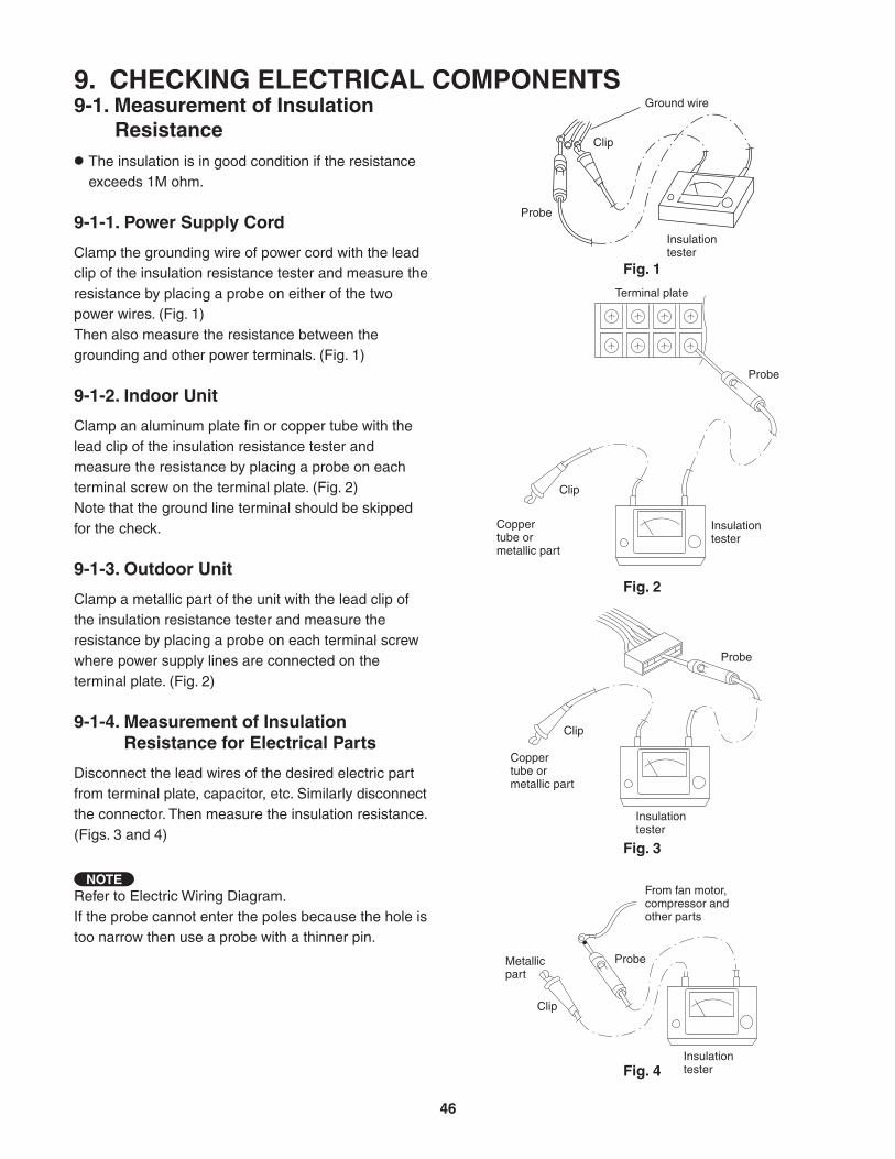
Insulation tester
Probe
Clip
Ground wire
Terminal plate
Coppertube ormetallic part
Clip
Insulation tester
Probe
Fig. 1
Fig. 2
Fig. 3
Fig. 4
Coppertube ormetallic part
Clip
Insulation tester
Probe
Clip
Insulation tester
ProbeMetallic part
From fan motor,compressor and other parts
9. CHECKING ELECTRICAL COMPONENTS9-1. Measurement of Insulation
ResistanceThe insulation is in good condition if the resistance exceeds 1M ohm.
9-1-1. Power Supply Cord
Clamp the grounding wire of power cord with the lead clip of the insulation resistance tester and measure the resistance by placing a probe on either of the two power wires. (Fig. 1)Then also measure the resistance between the grounding and other power terminals. (Fig. 1)
9-1-2. Indoor Unit
Clamp an aluminum plate fin or copper tube with the lead clip of the insulation resistance tester and measure the resistance by placing a probe on each terminal screw on the terminal plate. (Fig. 2) Note that the ground line terminal should be skipped for the check.
9-1-3. Outdoor Unit
Clamp a metallic part of the unit with the lead clip of the insulation resistance tester and measure the resistance by placing a probe on each terminal screw where power supply lines are connected on the terminal plate. (Fig. 2)
9-1-4. Measurement of Insulation Resistance for Electrical Parts
Disconnect the lead wires of the desired electric part from terminal plate, capacitor, etc. Similarly disconnect the connector. Then measure the insulation resistance. (Figs. 3 and 4)
Refer to Electric Wiring Diagram.If the probe cannot enter the poles because the hole is too narrow then use a probe with a thinner pin.
NOTE
46
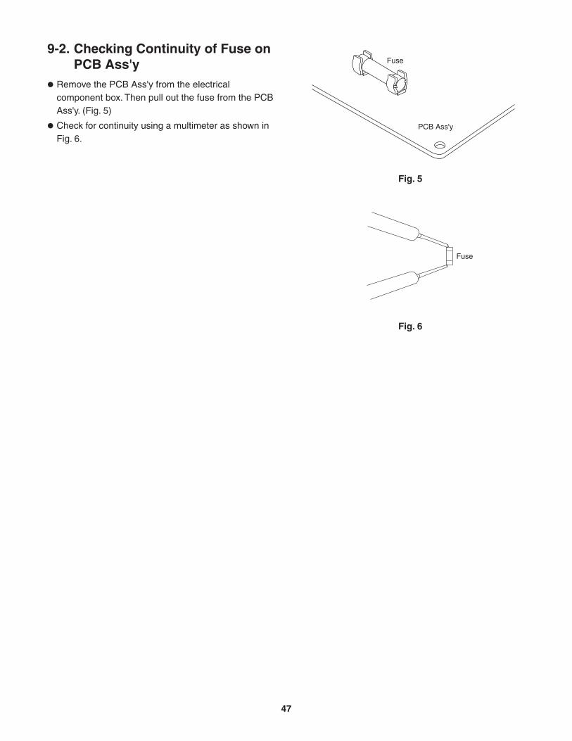
Fuse
PCB Ass'y
Fig. 5
Fig. 6
Fuse
9-2. Checking Continuity of Fuse on PCB Ass'y
Remove the PCB Ass'y from the electrical component box. Then pull out the fuse from the PCB Ass'y. (Fig. 5)
Check for continuity using a multimeter as shown in Fig. 6.
47
10. REFRIGERANT R410A: SPECIAL PRECAUTIONS WHEN SERVICING UNIT
10-1. Characteristics of New Refrigerant R410A10-1-1. What is New Refrigerant R410A?
R410A is a new refrigerant that contains two types of pseudo-non-azeotropic refrigerant mixture. Its refrigeration capacity and energy efficiency are about the same level as the conventional refrigerant, R22.
10-1-2. Components (mixing proportions)
HFC32 (50%) / HFC125 (50%)
10-1-3. Characteristics
Less toxic, more chemically stable refrigerant
The composition of refrigerant R410A changes whether it is in a gaseous phase or liquid phase. Thus, when there is a refrigerant leak the basic performance of the air conditioner may be degraded because of a change in composition of the remaining refrigerant. Therefore, do not add new refrigerant. Instead, recover the remaining refrigerant with the refrigerant recovery unit. Then, after evacuation, totally recharge the specified amount of refrigerant with the new refrigerant at its normal mixed composition state (in liquid phase).
When refrigerant R410A is used, the composition will differ depending on whether it is in gaseous or liquid phase, and the basic performance of the air conditioner will be degraded if it is charged while the refrigerant is in gaseous state. Thus, always charge the refrigerant while it is in liquid phase.
Ether-type oil is used for compressor oil for R410A-type units, which is different from the mineral oil used for R22. Thus more attention to moisture prevention and faster replacement work compared with conventional models are required.
CAUTION
48
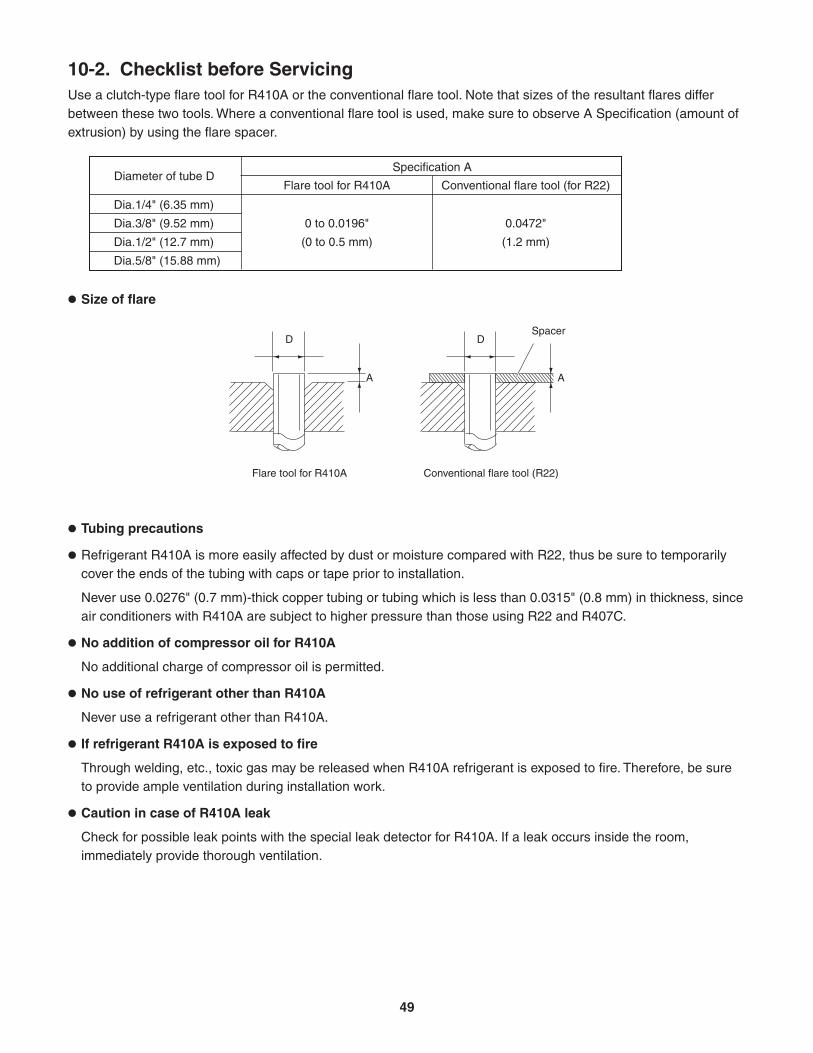
Tubing precautions
Refrigerant R410A is more easily affected by dust or moisture compared with R22, thus be sure to temporarily cover the ends of the tubing with caps or tape prior to installation.
Never use 0.0276" (0.7 mm)-thick copper tubing or tubing which is less than 0.0315" (0.8 mm) in thickness, since air conditioners with R410A are subject to higher pressure than those using R22 and R407C.
No addition of compressor oil for R410A
No additional charge of compressor oil is permitted.
No use of refrigerant other than R410A
Never use a refrigerant other than R410A.
If refrigerant R410A is exposed to fire
Through welding, etc., toxic gas may be released when R410A refrigerant is exposed to fire. Therefore, be sure to provide ample ventilation during installation work.
Caution in case of R410A leak
Check for possible leak points with the special leak detector for R410A. If a leak occurs inside the room, immediately provide thorough ventilation.
A
D
Flare tool for R410A
A
D
Conventional flare tool (R22)
Spacer
10-2. Checklist before ServicingUse a clutch-type flare tool for R410A or the conventional flare tool. Note that sizes of the resultant flares differ between these two tools. Where a conventional flare tool is used, make sure to observe A Specification (amount of extrusion) by using the flare spacer.
Size of flare
Specification ADiameter of tube D
Dia.1/4" (6.35 mm)
Dia.3/8" (9.52 mm)
Dia.1/2" (12.7 mm)
Dia.5/8" (15.88 mm)
Flare tool for R410A Conventional flare tool (for R22)
0 to 0.0196"
(0 to 0.5 mm)
0.0472"
(1.2 mm)
49
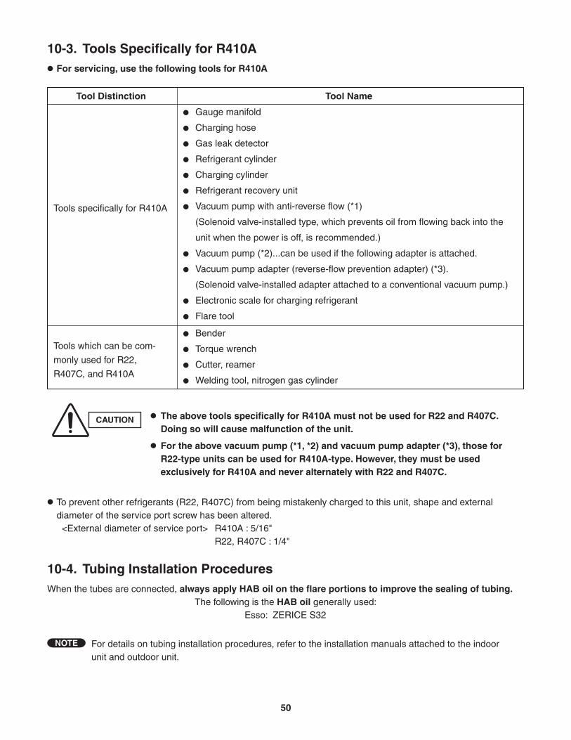
10-3. Tools Specifically for R410A For servicing, use the following tools for R410A
Gauge manifold
Charging hose
Gas leak detector
Refrigerant cylinder
Charging cylinder
Refrigerant recovery unit
Vacuum pump with anti-reverse flow (*1)
(Solenoid valve-installed type, which prevents oil from flowing back into the
unit when the power is off, is recommended.)
Vacuum pump (*2)...can be used if the following adapter is attached.
Vacuum pump adapter (reverse-flow prevention adapter) (*3).
(Solenoid valve-installed adapter attached to a conventional vacuum pump.)
Electronic scale for charging refrigerant
Flare tool
Bender
Torque wrench
Cutter, reamer
Welding tool, nitrogen gas cylinder
Tools specifically for R410A
Tool Distinction Tool Name
Tools which can be com-
monly used for R22,
R407C, and R410A
CAUTION The above tools specifically for R410A must not be used for R22 and R407C. Doing so will cause malfunction of the unit.
For the above vacuum pump (*1, *2) and vacuum pump adapter (*3), those for R22-type units can be used for R410A-type. However, they must be used exclusively for R410A and never alternately with R22 and R407C.
For details on tubing installation procedures, refer to the installation manuals attached to the indoor unit and outdoor unit.
To prevent other refrigerants (R22, R407C) from being mistakenly charged to this unit, shape and external diameter of the service port screw has been altered. <External diameter of service port> R410A : 5/16" R22, R407C : 1/4"
10-4. Tubing Installation ProceduresWhen the tubes are connected, always apply HAB oil on the flare portions to improve the sealing of tubing.
The following is the HAB oil generally used:Esso: ZERICE S32
NOTE
50
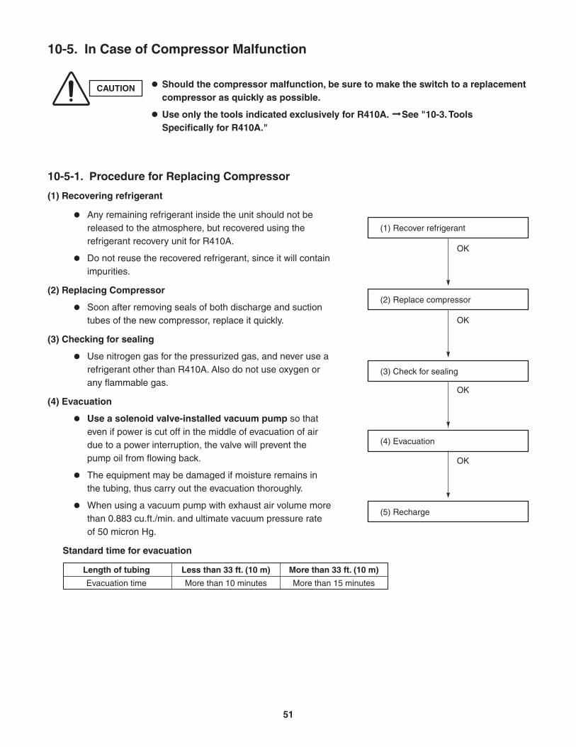
10-5. In Case of Compressor Malfunction
CAUTION Should the compressor malfunction, be sure to make the switch to a replacement compressor as quickly as possible.
Use only the tools indicated exclusively for R410A. See "10-3. ToolsSpecifically for R410A."
10-5-1. Procedure for Replacing Compressor
(1) Recovering refrigerant
Any remaining refrigerant inside the unit should not be released to the atmosphere, but recovered using the refrigerant recovery unit for R410A.
Do not reuse the recovered refrigerant, since it will contain impurities.
(2) Replacing Compressor
Soon after removing seals of both discharge and suction tubes of the new compressor, replace it quickly.
(3) Checking for sealing
Use nitrogen gas for the pressurized gas, and never use a refrigerant other than R410A. Also do not use oxygen or any flammable gas.
(4) Evacuation
Use a solenoid valve-installed vacuum pump so that even if power is cut off in the middle of evacuation of air due to a power interruption, the valve will prevent the pump oil from flowing back.
The equipment may be damaged if moisture remains in the tubing, thus carry out the evacuation thoroughly.
When using a vacuum pump with exhaust air volume more than 0.883 cu.ft./min. and ultimate vacuum pressure rate of 50 micron Hg.
Standard time for evacuation
(1) Recover refrigerant
OK
(2) Replace compressor
OK
(3) Check for sealing
OK
(4) Evacuation
OK
(5) Recharge
Length of tubing
Evacuation time
Less than 33 ft. (10 m)
More than 10 minutes
More than 33 ft. (10 m)
More than 15 minutes
51
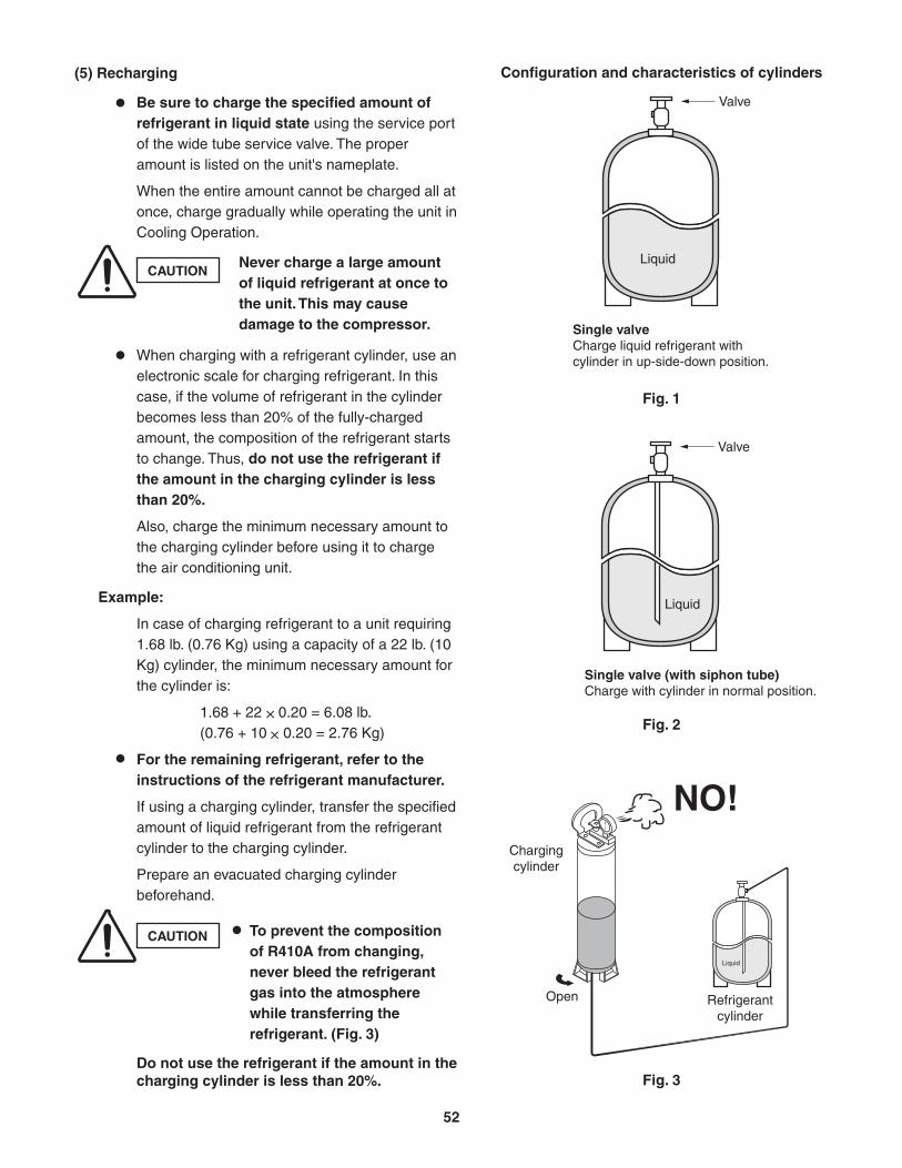
Valve
Single valveCharge liquid refrigerant with cylinder in up-side-down position.
Single valve (with siphon tube)Charge with cylinder in normal position.
Liquid
Valve
Liquid
Chargingcylinder
Open Refrigerantcylinder
Liquid
NO!
CAUTIONNever charge a large amount of liquid refrigerant at once to the unit. This may cause damage to the compressor.
CAUTION To prevent the composition of R410A from changing, never bleed the refrigerant gas into the atmosphere while transferring the refrigerant. (Fig. 3)
(5) Recharging
Be sure to charge the specified amount of refrigerant in liquid state using the service port of the wide tube service valve. The proper amount is listed on the unit's nameplate.
When the entire amount cannot be charged all at once, charge gradually while operating the unit in Cooling Operation.
When charging with a refrigerant cylinder, use an electronic scale for charging refrigerant. In this case, if the volume of refrigerant in the cylinder becomes less than 20% of the fully-charged amount, the composition of the refrigerant starts to change. Thus, do not use the refrigerant if the amount in the charging cylinder is less than 20%.
Also, charge the minimum necessary amount to the charging cylinder before using it to charge the air conditioning unit.
Example:
In case of charging refrigerant to a unit requiring 1.68 lb. (0.76 Kg) using a capacity of a 22 lb. (10 Kg) cylinder, the minimum necessary amount for the cylinder is:
1.68 + 22 0.20 = 6.08 lb.(0.76 + 10 0.20 = 2.76 Kg)
For the remaining refrigerant, refer to the instructions of the refrigerant manufacturer.
If using a charging cylinder, transfer the specified amount of liquid refrigerant from the refrigerant cylinder to the charging cylinder.
Prepare an evacuated charging cylinder beforehand.
Do not use the refrigerant if the amount in the charging cylinder is less than 20%.
Configuration and characteristics of cylinders
Fig. 1
Fig. 2
Fig. 3
52
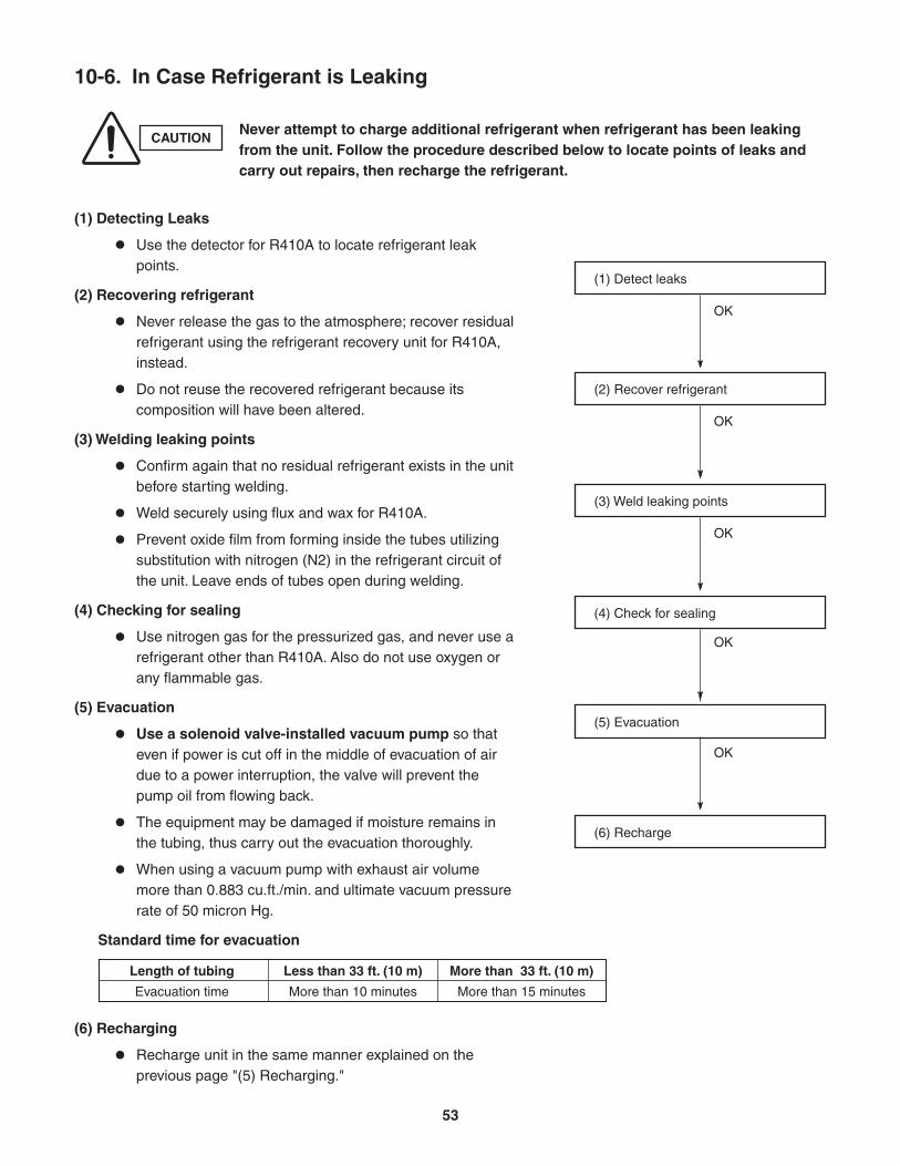
Length of tubing
Evacuation time
Less than 33 ft. (10 m)
More than 10 minutes
More than 33 ft. (10 m)
More than 15 minutes
10-6. In Case Refrigerant is Leaking
CAUTIONNever attempt to charge additional refrigerant when refrigerant has been leaking from the unit. Follow the procedure described below to locate points of leaks and carry out repairs, then recharge the refrigerant.
(1) Detecting Leaks
Use the detector for R410A to locate refrigerant leak points.
(2) Recovering refrigerant
Never release the gas to the atmosphere; recover residual refrigerant using the refrigerant recovery unit for R410A, instead.
Do not reuse the recovered refrigerant because its composition will have been altered.
(3) Welding leaking points
Confirm again that no residual refrigerant exists in the unit before starting welding.
Weld securely using flux and wax for R410A.
Prevent oxide film from forming inside the tubes utilizing substitution with nitrogen (N2) in the refrigerant circuit of the unit. Leave ends of tubes open during welding.
(4) Checking for sealing
Use nitrogen gas for the pressurized gas, and never use a refrigerant other than R410A. Also do not use oxygen or any flammable gas.
(5) Evacuation
Use a solenoid valve-installed vacuum pump so that even if power is cut off in the middle of evacuation of air due to a power interruption, the valve will prevent the pump oil from flowing back.
The equipment may be damaged if moisture remains in the tubing, thus carry out the evacuation thoroughly.
When using a vacuum pump with exhaust air volume more than 0.883 cu.ft./min. and ultimate vacuum pressure rate of 50 micron Hg.
Standard time for evacuation
(6) Recharging
Recharge unit in the same manner explained on the previous page "(5) Recharging."
(2) Recover refrigerant
OK
(3) Weld leaking points
OK
(4) Check for sealing
OK
(5) Evacuation
OK
(6) Recharge
(1) Detect leaks
OK
53
10-7. Charging Additional Refrigerant
10-7-1. When Tubes are Extended
Observe the proper amount of refrigerant as stated in this service manual or the installation manual that came with the indoor unit. Charge additional refrigerant in liquid state only.
10-8. Retro-Fitting Existing Systems
10-8-1. Use of Existing Units
Never use new refrigerant R410A for existing units which use R22. This will cause the air conditioner to operate improperly and may result in a hazardous condition.
10-8-2. Use of Existing Tubing
If replacing an older unit that used refrigerant R22 with a R410A unit, do not use its existing tubing. Instead, completely new tubing must be used.
CAUTIONNever charge additional refrigerant if refrigerant is leaking from the unit. Follow instructions given in "10-6. In Case Refrigerant is Leaking" and completely carry out repairs. Only then should you recharge the refrigerant.
54

Operating Instructions
CS-KS30NKU + CU-KS30NKUACS-KS36NKU + CU-KS36NKUA
(852-6-4181-220-00-2)
APPENDIX A
A-1
This air conditioner uses the refrigerant R410A.
Split System Air Conditioner
Model No.
Panasonic Corporation1006 Kadoma, Kadoma City, Osaka, Japan
85264181220002
Indoor Units
CS-KS30NKUCS-KS36NKU
Outdoor Units
CU-KS30NKUACU-KS36NKUA
Operating Instructions
Before operating the unit, read these operating instructions thoroughly and keep them for future reference.
CV6233187105
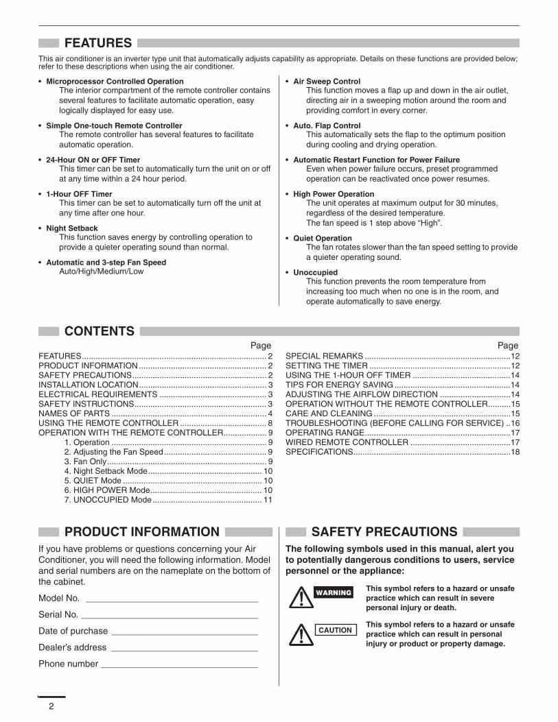
2
FEATURESThis air conditioner is an inverter type unit that automatically adjusts capability as appropriate. Details on these functions are provided below; refer to these descriptions when using the air conditioner.
• Microprocessor Controlled OperationThe interior compartment of the remote controller contains several features to facilitate automatic operation, easy logically displayed for easy use.
• Simple One-touch Remote ControllerThe remote controller has several features to facilitate automatic operation.
• 24-Hour ON or OFF TimerThis timer can be set to automatically turn the unit on or off at any time within a 24 hour period.
• 1-Hour OFF TimerThis timer can be set to automatically turn off the unit at any time after one hour.
• Night SetbackThis function saves energy by controlling operation to provide a quieter operating sound than normal.
• Automatic and 3-step Fan SpeedAuto/High/Medium/Low
• Air Sweep ControlThis function moves a flap up and down in the air outlet, directing air in a sweeping motion around the room and providing comfort in every corner.
• Auto. Flap ControlThis automatically sets the flap to the optimum position during cooling and drying operation.
• Automatic Restart Function for Power FailureEven when power failure occurs, preset programmed operation can be reactivated once power resumes.
• High Power OperationThe unit operates at maximum output for 30 minutes, regardless of the desired temperature.The fan speed is 1 step above “High”.
• Quiet OperationThe fan rotates slower than the fan speed setting to provide a quieter operating sound.
• UnoccupiedThis function prevents the room temperature from increasing too much when no one is in the room, and operate automatically to save energy.
CONTENTSPage Page
FEATURES................................................................................. 2PRODUCT INFORMATION ........................................................ 2SAFETY PRECAUTIONS........................................................... 2INSTALLATION LOCATION........................................................ 3ELECTRICAL REQUIREMENTS ............................................... 3SAFETY INSTRUCTIONS.......................................................... 3NAMES OF PARTS .................................................................... 4USING THE REMOTE CONTROLLER ...................................... 8OPERATION WITH THE REMOTE CONTROLLER................... 9
1. Operation .................................................................... 92. Adjusting the Fan Speed............................................. 93. Fan Only...................................................................... 94. Night Setback Mode.................................................. 105. QUIET Mode ............................................................. 106. HIGH POWER Mode................................................. 107. UNOCCUPIED Mode ................................................ 11
SPECIAL REMARKS ................................................................12SETTING THE TIMER ..............................................................12USING THE 1-HOUR OFF TIMER ...........................................14TIPS FOR ENERGY SAVING ...................................................14ADJUSTING THE AIRFLOW DIRECTION ...............................14OPERATION WITHOUT THE REMOTE CONTROLLER..........15CARE AND CLEANING ............................................................15TROUBLESHOOTING (BEFORE CALLING FOR SERVICE) ..16OPERATING RANGE................................................................17WIRED REMOTE CONTROLLER ............................................17SPECIFICATIONS.....................................................................18
PRODUCT INFORMATIONIf you have problems or questions concerning your Air Conditioner, you will need the following information. Model and serial numbers are on the nameplate on the bottom of the cabinet.
Model No. __________________________________
Serial No. ___________________________________
Date of purchase _____________________________
Dealer’s address _____________________________
Phone number _______________________________
SAFETY PRECAUTIONSThe following symbols used in this manual, alert you to potentially dangerous conditions to users, service personnel or the appliance:
This symbol refers to a hazard or unsafe practice which can result in severe personal injury or death.
This symbol refers to a hazard or unsafe practice which can result in personal injury or product or property damage.
CAUTION
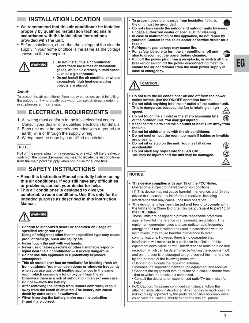
3
INSTALLATION LOCATION• We recommend that this air conditioner be installed
properly by qualified installation technicians in accordance with the Installation Instructions provided with the unit.
• Before installation, check that the voltage of the electric supply in your home or office is the same as the voltage shown on the nameplate.
Avoid: To protect the air conditioner from heavy corrosion, avoid installing the outdoor unit where salty sea water can splash directly onto it or in sulphurous air near a spa.
ELECTRICAL REQUIREMENTS1. All wiring must conform to the local electrical codes.
Consult your dealer or a qualified electrician for details.2. Each unit must be properly grounded with a ground (or
earth) wire or through the supply wiring.3. Wiring must be done by a qualified electrician.
Pull off the power plug from a receptacle, or switch off the breaker, or switch off the power disconnecting mean to isolate the air conditioner from the main power supply when not in use for a long time.
SAFETY INSTRUCTIONS• Read this Instruction Manual carefully before using
this air conditioner. If you still have any difficulties or problems, consult your dealer for help.
• This air conditioner is designed to give you comfortable room conditions. Use this only for its intended purpose as described in this Instruction Manual.
• Do not install this air conditioner where there are fumes or flammable gases, or in an extremely humid space such as a greenhouse.
• Do not install the air conditioner where excessively high heat-generating objects are placed.
• Confirm to authorized dealer or specialist on usage of specified refrigerant type.Using of refrigerant other than the specified type may cause product damage, burst and injury etc.
• Never touch the unit with wet hands.• Never use or store gasoline or other flammable vapor or
liquid near the air conditioner — it is very dangerous.• Do not use this appliance in a potentially explosive
atmosphere.• This air conditioner has no ventilator for intaking fresh air
from outdoors. You must open doors or windows frequently when you use gas or oil heating appliances in the same room, which consume a lot of oxygen from the air. Otherwise there is a risk of suffocation in an extreme case.
• Do not swallow the battery.• After removing the battery from remote controller, keep it
away from the reach of children. The battery can cause death by suffocation if swallowed.
• When inserting the battery, make sure the polarities (+ and -) are correct.
NOTE
• To prevent possible hazards from insulation failure, the unit must be grounded.
• Do not clean inside the indoor and outdoor units by users. Engage authorized dealer or specialist for cleaning.
• In case of malfunction of this appliance, do not repair by yourself. Contact to the sales dealer or service dealer for a repair.
• Refrigerant gas leakage may cause fire.• For safety, be sure to turn the air conditioner off and
also to disconnect the power before cleaning.• Pull off the power plug from a receptacle, or switch off the
breaker, or switch off the power disconnecting mean to isolate the air conditioner from the main power supply in case of emergency.
• Do not turn the air conditioner on and off from the power mains switch. Use the ON/OFF operation button.
• Do not stick anything into the air outlet of the outdoor unit. This is dangerous because the fan is rotating at high speed.
• Do not touch the air inlet or the sharp aluminum fins of the outdoor unit. You may get injured.
• Keep the fire alarm and the air outlet at least 1.5m away from the unit.
• Do not let children play with the air conditioner.• Do not cool or heat the room too much if babies or invalids
are present.• Do not sit or step on the unit. You may fall down
accidentally.• Do not stick any object into the FAN CASE.
You may be injured and the unit may be damaged.
• This device complies with part 15 of the FCC Rules.Operation is subject to the following two conditions:(1) This device may not cause harmful interference, and (2) this device must accept any interference received, including interference that may cause undesired operation.
• This equipment has been tested and found to comply with the limits for a Class B digital device, pursuant to part 15 of the FCC Rules.These limits are designed to provide reasonable protection against harmful interference in a residential installation. Thisequipment generates, uses and can radiate radio frequency energy and, if not installed and used in accordance with the instructions, may cause harmful interference to radio communications. However, there is no guarantee that interference will not occur in a particular installation. If this equipment does cause harmful interference to radio or television reception, which can be determined by turning the equipment off and on, the user is encouraged to try to correct the interference by one or more of the following measures:• Reorient or relocate the receiving antenna.• Increase the separation between the equipment and receiver.• Connect the equipment into an outlet on a circuit different from
that to which the receiver is connected.• Consult the dealer or an experienced radio/TV technician for
help.• FCC Caution: To assure continued compliance, follow the
attached installation instructions. Any changes or modifications not expressly approved by the party responsible for compliance could void the user's authority to operate this equipment.
CAUTION
NOTICE
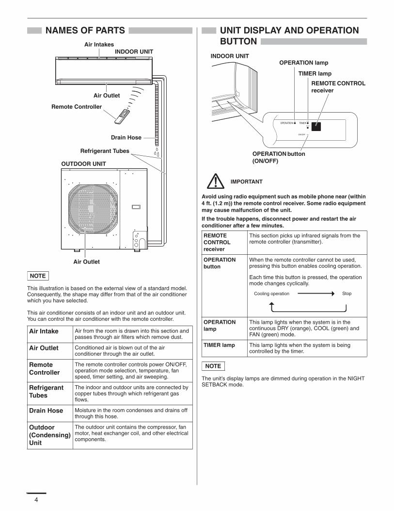
4
NAMES OF PARTS
This illustration is based on the external view of a standard model.Consequently, the shape may differ from that of the air conditioner which you have selected.
This air conditioner consists of an indoor unit and an outdoor unit. You can control the air conditioner with the remote controller.
UNIT DISPLAY AND OPERATION BUTTON
Avoid using radio equipment such as mobile phone near (within 4 ft. (1.2 m)) the remote control receiver. Some radio equipment may cause malfunction of the unit.
If the trouble happens, disconnect power and restart the air conditioner after a few minutes.
The unit’s display lamps are dimmed during operation in the NIGHT SETBACK mode.
Air Intake Air from the room is drawn into this section and passes through air filters which remove dust.
Air Outlet Conditioned air is blown out of the air conditioner through the air outlet.
Remote Controller
The remote controller controls power ON/OFF, operation mode selection, temperature, fan speed, timer setting, and air sweeping.
Refrigerant Tubes
The indoor and outdoor units are connected by copper tubes through which refrigerant gas flows.
Drain Hose Moisture in the room condenses and drains off through this hose.
Outdoor (Condensing) Unit
The outdoor unit contains the compressor, fan motor, heat exchanger coil, and other electrical components.
INDOOR UNITAir Intakes
Remote Controller
Refrigerant Tubes
Drain Hose
OUTDOOR UNIT
Air Outlet
Air Outlet
NOTE
REMOTE CONTROL receiver
This section picks up infrared signals from the remote controller (transmitter).
OPERATION button
When the remote controller cannot be used, pressing this button enables cooling operation.
Each time this button is pressed, the operation mode changes cyclically.
OPERATION lamp
This lamp lights when the system is in the continuous DRY (orange), COOL (green) and FAN (green) mode.
TIMER lamp This lamp lights when the system is being controlled by the timer.
REMOTE CONTROL receiver
TIMER lamp
OPERATION lamp
OPERATION button (ON/OFF)
INDOOR UNIT
IMPORTANT
Cooling operation Stop
NOTE
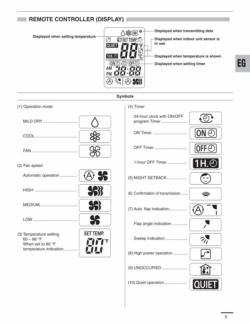
5
REMOTE CONTROLLER (DISPLAY)
(1) Operation mode
MILD DRY ..............................
COOL.....................................
FAN ........................................
(2) Fan speed
Automatic operation ...............
HIGH .....................................
MEDIUM.................................
LOW .......................................
(3) Temperature setting 60 – 86 °FWhen set to 80 °F temperature indication............
(4) Timer
24-hour clock with ON/OFF program Timer .......................
ON Timer. ..............................
OFF Timer. ............................
1-hour OFF Timer. .................
(5) NIGHT SETBACK..................
(6) Confirmation of transmission .......
(7) Auto. flap indication................
Flap angle indication..............
Sweep indication....................
(8) High power operation.............
(9) UNOCCUPIED ......................
(10) Quiet operation ....................
Displayed when setting timer
Displayed when transmitting data
Displayed when indoor unit sensor is in use
Displayed when setting temperature
Displayed when temperature is shown
Symbols
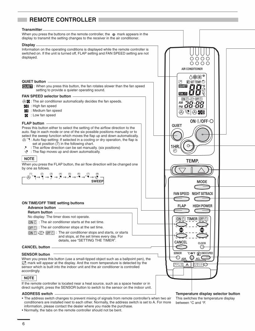
6
REMOTE CONTROLLER
TransmitterWhen you press the buttons on the remote controller, the mark appears in the display to transmit the setting changes to the receiver in the air conditioner.
DisplayInformation on the operating conditions is displayed while the remote controller is switched on. If the unit is turned off, FLAP setting and FAN SPEED setting are not displayed.
FAN SPEED selector button: The air conditioner automatically decides the fan speeds.: High fan speed: Medium fan speed: Low fan speed
FLAP buttonPress this button either to select the setting of the airflow direction to the auto. flap in each mode or one of the six possible positions manually or to select the sweep function which moves the flap up and down automatically.
: Auto flap setting: If selected in a cooling or dry operation, the flap is set at position (7) in the following chart.
: The airflow direction can be set manually. (six positions): The flap moves up and down automatically.
When you press the FLAP button, the air flow direction will be changed one by one as follows.
NOTE
SWEEP
CANCEL button
SENSOR buttonWhen you press this button (use a small-tipped object such as a ballpoint pen), the
mark will appear at the display. And the room temperature is detected by the sensor which is built into the indoor unit and the air conditioner is controlled accordingly.
If the remote controller is located near a heat source, such as a space heater or in direct sunlight, press the SENSOR button to switch to the sensor on the indoor unit.
NOTE
ADDRESS switch• The address switch changes to prevent mixing of signals from remote controller’s when two air
conditioners are installed next to each other. Normally, the address switch is set to A. For more information, please contact the dealer where you made the purchase.
• Normally, the tabs on the remote controller should not be bent.
Temperature display selector buttonThis switches the temperature display between °C and °F.
QUIET button: When you press this button, the fan rotates slower than the fan speed
setting to provide a quieter operating sound.
ON TIME/OFF TIME setting buttonsAdvance buttonReturn buttonNo display: The timer does not operate.
: The air conditioner starts at the set time.
: The air conditioner stops at the set time.
: The air conditioner stops and starts, or starts and stops, at the set times every day. For details, see “SETTING THE TIMER”.
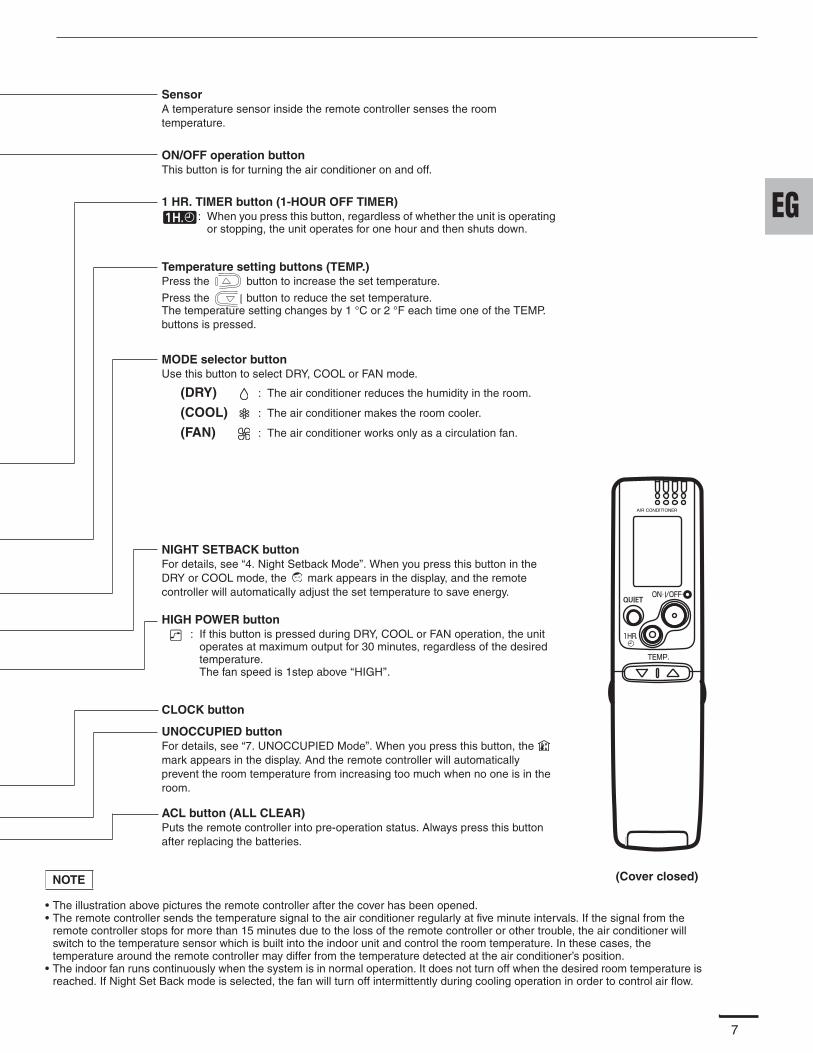
7
SensorA temperature sensor inside the remote controller senses the room temperature.
(Cover closed)
CLOCK button
ACL button (ALL CLEAR)Puts the remote controller into pre-operation status. Always press this button after replacing the batteries.
ON/OFF operation buttonThis button is for turning the air conditioner on and off.
1 HR. TIMER button (1-HOUR OFF TIMER): When you press this button, regardless of whether the unit is operating
or stopping, the unit operates for one hour and then shuts down.
Temperature setting buttons (TEMP.)Press the button to increase the set temperature.
Press the button to reduce the set temperature.The temperature setting changes by 1 °C or 2 °F each time one of the TEMP. buttons is pressed.
MODE selector buttonUse this button to select DRY, COOL or FAN mode.
(DRY) : The air conditioner reduces the humidity in the room.
(COOL) : The air conditioner makes the room cooler.
(FAN) : The air conditioner works only as a circulation fan.
NIGHT SETBACK buttonFor details, see “4. Night Setback Mode”. When you press this button in the DRY or COOL mode, the mark appears in the display, and the remote controller will automatically adjust the set temperature to save energy.
HIGH POWER button: If this button is pressed during DRY, COOL or FAN operation, the unit
operates at maximum output for 30 minutes, regardless of the desired temperature.The fan speed is 1step above ‘‘HIGH’’.
UNOCCUPIED buttonFor details, see “7. UNOCCUPIED Mode”. When you press this button, the mark appears in the display. And the remote controller will automatically prevent the room temperature from increasing too much when no one is in the room.
• The illustration above pictures the remote controller after the cover has been opened.• The remote controller sends the temperature signal to the air conditioner regularly at five minute intervals. If the signal from the
remote controller stops for more than 15 minutes due to the loss of the remote controller or other trouble, the air conditioner will switch to the temperature sensor which is built into the indoor unit and control the room temperature. In these cases, the temperature around the remote controller may differ from the temperature detected at the air conditioner’s position.
• The indoor fan runs continuously when the system is in normal operation. It does not turn off when the desired room temperature is reached. If Night Set Back mode is selected, the fan will turn off intermittently during cooling operation in order to control air flow.
NOTE
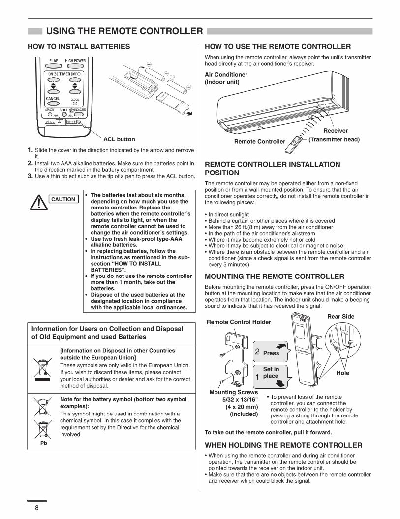
8
USING THE REMOTE CONTROLLER
HOW TO INSTALL BATTERIES
1. Slide the cover in the direction indicated by the arrow and remove it.
2. Install two AAA alkaline batteries. Make sure the batteries point in the direction marked in the battery compartment.
3. Use a thin object such as the tip of a pen to press the ACL button.
HOW TO USE THE REMOTE CONTROLLERWhen using the remote controller, always point the unit’s transmitter head directly at the air conditioner’s receiver.
REMOTE CONTROLLER INSTALLATION POSITIONThe remote controller may be operated either from a non-fixed position or from a wall-mounted position. To ensure that the air conditioner operates correctly, do not install the remote controller in the following places:
• In direct sunlight• Behind a curtain or other places where it is covered• More than 26 ft.(8 m) away from the air conditioner• In the path of the air conditioner’s airstream• Where it may become extremely hot or cold• Where it may be subject to electrical or magnetic noise• Where there is an obstacle between the remote controller and air
conditioner (since a check signal is sent from the remote controller every 5 minutes)
MOUNTING THE REMOTE CONTROLLERBefore mounting the remote controller, press the ON/OFF operation button at the mounting location to make sure that the air conditioner operates from that location. The indoor unit should make a beeping sound to indicate that it has received the signal.
To take out the remote controller, pull it forward.
WHEN HOLDING THE REMOTE CONTROLLER• When using the remote controller and during air conditioner
operation, the transmitter on the remote controller should be pointed towards the receiver on the indoor unit.
• Make sure that there are no objects between the remote controller and receiver which could block the signal.
• The batteries last about six months, depending on how much you use the remote controller. Replace the batteries when the remote controller’s display fails to light, or when the remote controller cannot be used to change the air conditioner’s settings.
• Use two fresh leak-proof type-AAA alkaline batteries.
• In replacing batteries, follow the instructions as mentioned in the sub-section “HOW TO INSTALL BATTERIES”.
• If you do not use the remote controller more than 1 month, take out the batteries.
• Dispose of the used batteries at the designated location in compliance with the applicable local ordinances.
Information for Users on Collection and Disposal of Old Equipment and used Batteries
[Information on Disposal in other Countries outside the European Union]These symbols are only valid in the European Union. If you wish to discard these items, please contact your local authorities or dealer and ask for the correct method of disposal.
Note for the battery symbol (bottom two symbol examples):This symbol might be used in combination with a chemical symbol. In this case it complies with the requirement set by the Directive for the chemical involved.
ACL button
CAUTION
Pb
Air Conditioner (Indoor unit)
Receiver
Remote Controller (Transmitter head)
• To prevent loss of the remote controller, you can connect the remote controller to the holder by passing a string through the remote controller and attachment hole.
Remote Control Holder
Mounting Screws5/32 x 13/16"(4 x 20 mm)
(included)
Rear Side
Hole
Press
Set in place
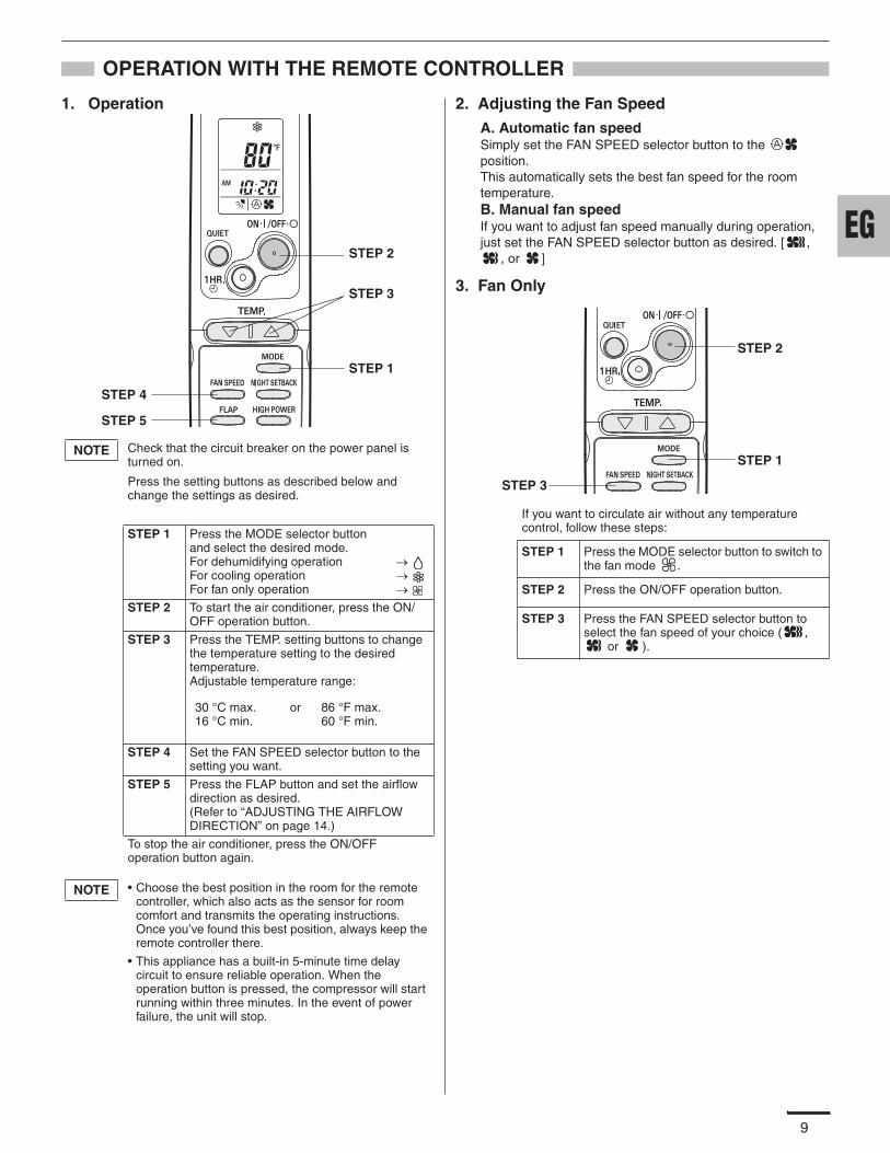
9
OPERATION WITH THE REMOTE CONTROLLER
1. Operation 2. Adjusting the Fan Speed
A. Automatic fan speedSimply set the FAN SPEED selector button to the position.This automatically sets the best fan speed for the room temperature.B. Manual fan speedIf you want to adjust fan speed manually during operation, just set the FAN SPEED selector button as desired. [ ,
, or ]
3. Fan Only
Check that the circuit breaker on the power panel is turned on.
Press the setting buttons as described below and change the settings as desired.
STEP 1 Press the MODE selector button and select the desired mode.For dehumidifying operationFor cooling operationFor fan only operation
STEP 2 To start the air conditioner, press the ON/OFF operation button.
STEP 3 Press the TEMP. setting buttons to change the temperature setting to the desired temperature.Adjustable temperature range:
STEP 4 Set the FAN SPEED selector button to the setting you want.
STEP 5 Press the FLAP button and set the airflow direction as desired.(Refer to “ADJUSTING THE AIRFLOW DIRECTION” on page 14.)
To stop the air conditioner, press the ON/OFF operation button again.
• Choose the best position in the room for the remote controller, which also acts as the sensor for room comfort and transmits the operating instructions. Once you’ve found this best position, always keep the remote controller there.
• This appliance has a built-in 5-minute time delay circuit to ensure reliable operation. When the operation button is pressed, the compressor will start running within three minutes. In the event of power failure, the unit will stop.
STEP 2
STEP 1
STEP 3
STEP 4
STEP 5
NOTE
30 °C max. 16 °C min.
or 86 °F max. 60 °F min.
NOTE
If you want to circulate air without any temperature control, follow these steps:
STEP 1 Press the MODE selector button to switch to the fan mode .
STEP 2 Press the ON/OFF operation button.
STEP 3 Press the FAN SPEED selector button to select the fan speed of your choice ( ,
or ).
STEP 2
STEP 1
STEP 3
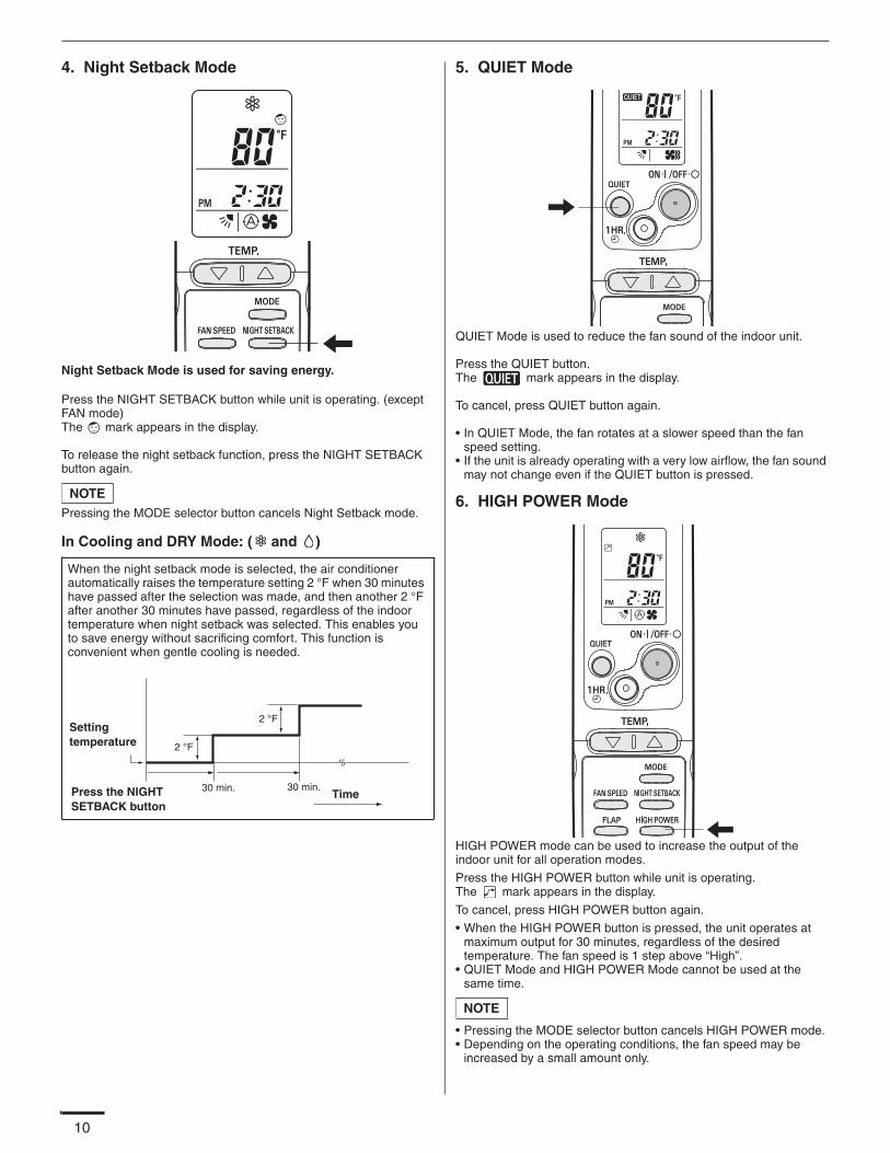
10
4. Night Setback Mode
Night Setback Mode is used for saving energy.
Press the NIGHT SETBACK button while unit is operating. (except FAN mode)The mark appears in the display.
To release the night setback function, press the NIGHT SETBACK button again.
Pressing the MODE selector button cancels Night Setback mode.
In Cooling and DRY Mode: ( and )
5. QUIET Mode
QUIET Mode is used to reduce the fan sound of the indoor unit.
Press the QUIET button.The mark appears in the display.
To cancel, press QUIET button again.
• In QUIET Mode, the fan rotates at a slower speed than the fan speed setting.
• If the unit is already operating with a very low airflow, the fan sound may not change even if the QUIET button is pressed.
6. HIGH POWER Mode
HIGH POWER mode can be used to increase the output of the indoor unit for all operation modes.
Press the HIGH POWER button while unit is operating.The mark appears in the display.
To cancel, press HIGH POWER button again.
• When the HIGH POWER button is pressed, the unit operates at maximum output for 30 minutes, regardless of the desired temperature. The fan speed is 1 step above “High”.
• QUIET Mode and HIGH POWER Mode cannot be used at the same time.
• Pressing the MODE selector button cancels HIGH POWER mode. • Depending on the operating conditions, the fan speed may be
increased by a small amount only.
NOTE
When the night setback mode is selected, the air conditioner automatically raises the temperature setting 2 °F when 30 minutes have passed after the selection was made, and then another 2 °F after another 30 minutes have passed, regardless of the indoor temperature when night setback was selected. This enables you to save energy without sacrificing comfort. This function is convenient when gentle cooling is needed.
Settingtemperature
Press the NIGHT SETBACK button
30 min. 30 min.Time
2 °F
2 °F
NOTE
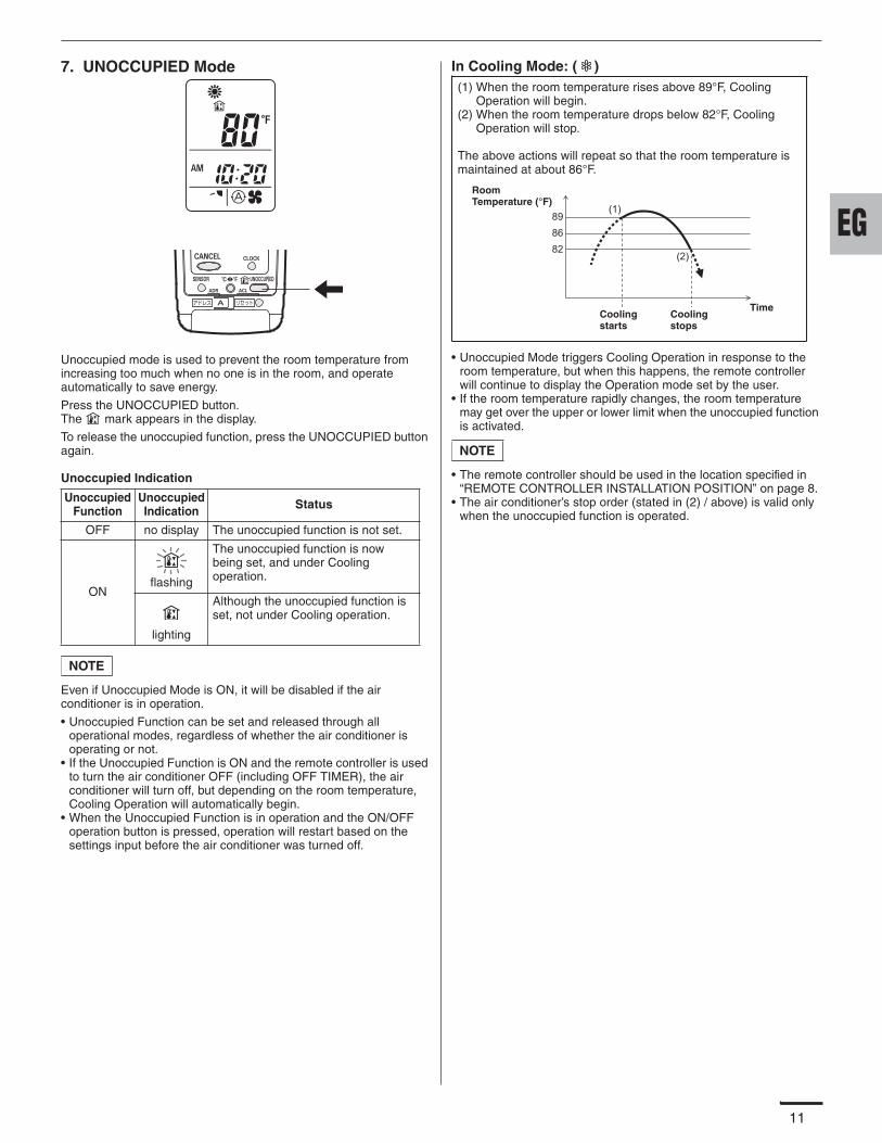
11
7. UNOCCUPIED Mode
Unoccupied mode is used to prevent the room temperature from increasing too much when no one is in the room, and operate automatically to save energy.
Press the UNOCCUPIED button.The mark appears in the display.
To release the unoccupied function, press the UNOCCUPIED button again.
Unoccupied Indication
Even if Unoccupied Mode is ON, it will be disabled if the air conditioner is in operation.
• Unoccupied Function can be set and released through all operational modes, regardless of whether the air conditioner is operating or not.
• If the Unoccupied Function is ON and the remote controller is used to turn the air conditioner OFF (including OFF TIMER), the air conditioner will turn off, but depending on the room temperature, Cooling Operation will automatically begin.
• When the Unoccupied Function is in operation and the ON/OFF operation button is pressed, operation will restart based on the settings input before the air conditioner was turned off.
In Cooling Mode: ( )
• Unoccupied Mode triggers Cooling Operation in response to the room temperature, but when this happens, the remote controller will continue to display the Operation mode set by the user.
• If the room temperature rapidly changes, the room temperature may get over the upper or lower limit when the unoccupied function is activated.
• The remote controller should be used in the location specified in “REMOTE CONTROLLER INSTALLATION POSITION” on page 8.
• The air conditioner’s stop order (stated in (2) / above) is valid only when the unoccupied function is operated.
Unoccupied Function
Unoccupied Indication Status
OFF no display The unoccupied function is not set.
ONflashing
The unoccupied function is now being set, and under Cooling operation.
lighting
Although the unoccupied function is set, not under Cooling operation.
NOTE
(1)898682
(2)
Room Temperature (°F)
Cooling starts
TimeCooling stops
(1) When the room temperature rises above 89°F, Cooling Operation will begin.
(2) When the room temperature drops below 82°F, Cooling Operation will stop.
The above actions will repeat so that the room temperature is maintained at about 86°F.
NOTE
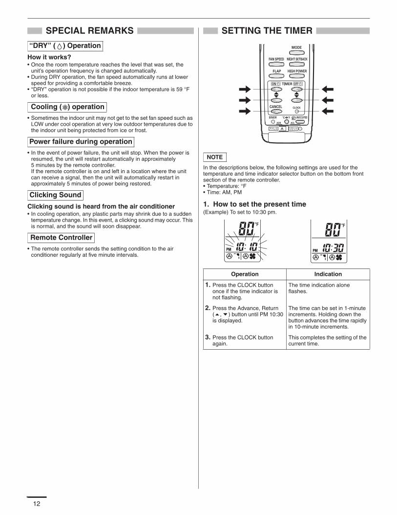
12
SPECIAL REMARKS
How it works?• Once the room temperature reaches the level that was set, the
unit’s operation frequency is changed automatically.• During DRY operation, the fan speed automatically runs at lower
speed for providing a comfortable breeze.• ‘‘DRY’’ operation is not possible if the indoor temperature is 59 °F
or less.
• Sometimes the indoor unit may not get to the set fan speed such as LOW under cool operation at very low outdoor temperatures due to the indoor unit being protected from ice or frost.
• In the event of power failure, the unit will stop. When the power is resumed, the unit will restart automatically in approximately 5 minutes by the remote controller.If the remote controller is on and left in a location where the unit can receive a signal, then the unit will automatically restart in approximately 5 minutes of power being restored.
Clicking sound is heard from the air conditioner• In cooling operation, any plastic parts may shrink due to a sudden
temperature change. In this event, a clicking sound may occur. This is normal, and the sound will soon disappear.
• The remote controller sends the setting condition to the air conditioner regularly at five minute intervals.
SETTING THE TIMER
In the descriptions below, the following settings are used for the temperature and time indicator selector button on the bottom front section of the remote controller.• Temperature: °F• Time: AM, PM
1. How to set the present time(Example) To set to 10:30 pm.
‘‘DRY’’ ( ) Operation
Cooling ( ) operation
Power failure during operation
Clicking Sound
Remote Controller
Operation Indication
1. Press the CLOCK button once if the time indicator is not flashing.
The time indication alone flashes.
2. Press the Advance, Return ( , ) button until PM 10:30 is displayed.
The time can be set in 1-minute increments. Holding down the button advances the time rapidly in 10-minute increments.
3. Press the CLOCK button again.
This completes the setting of the current time.
NOTE
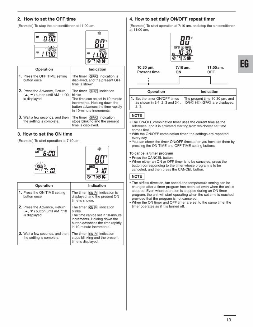
13
2. How to set the OFF time(Example) To stop the air conditioner at 11:00 am.
3. How to set the ON time(Example) To start operation at 7:10 am.
4. How to set daily ON/OFF repeat timer(Example) To start operation at 7:10 am. and stop the air conditioner at 11:00 am.
• The ON/OFF combination timer uses the current time as the reference, and it is activated starting from whichever set time comes first.
• With the ON/OFF combination timer, the settings are repeated every day.
• You can check the timer ON/OFF times after you have set them by pressing the ON TIME and OFF TIME setting buttons.
To cancel a timer program• Press the CANCEL button.• When either an ON or OFF timer is to be canceled, press the
button corresponding to the timer whose program is to be canceled, and then press the CANCEL button.
• The airflow direction, fan speed and temperature setting can be changed after a timer program has been set even when the unit is stopped. Even when operation is stopped during an ON timer program, the unit will start operating when the set time is reached provided that the program is not canceled.
• When the ON timer and OFF timer are set to the same time, the timer operates as if it is turned off.
Operation Indication
1. Press the OFF TIME setting button once.
The timer indication is displayed, and the present OFF time is shown.
2. Press the Advance, Return ( , ) button until AM 11:00 is displayed.
The timer indication blinks.The time can be set in 10-minute increments. Holding down the button advances the time rapidly in 10-minute increments.
3. Wait a few seconds, and then the setting is complete.
The timer indication stops blinking and the present time is displayed.
Operation Indication
1. Press the ON TIME setting button once.
The timer indication is displayed, and the present ON time is shown.
2. Press the Advance, Return ( , ) button until AM 7:10 is displayed.
The timer indication blinks.The time can be set in 10-minute increments. Holding down the button advances the time rapidly in 10-minute increments.
3. Wait a few seconds, and then the setting is complete.
The timer indication stops blinking and the present time is displayed.
Operation Indication
1. Set the timer ON/OFF times as shown in 2-1, 2, 3 and 3-1, 2, 3.
The present time 10:30 pm. and are displayed.
7:10 am. ON
11:00 am. OFF
10:30 pm. Present time
NOTE
NOTE
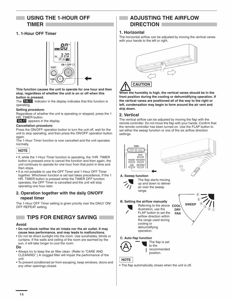
14
USING THE 1-HOUR OFF TIMER
1. 1-Hour OFF Timer
This function causes the unit to operate for one hour and then stop, regardless of whether the unit is on or off when this button is pressed.The indicator in the display indicates that this function is operating.
Setting procedure:Regardless of whether the unit is operating or stopped, press the 1 HR. TIMER button.
appears in the display.
Cancellation procedure:Press the ON/OFF operation button to turn the unit off, wait for the unit to stop operating, and then press the ON/OFF operation button again. The 1-Hour Timer function is now cancelled and the unit operates normally.
• If, while the 1-Hour Timer function is operating, the 1HR. TIMER button is pressed once to cancel the function and then again, the unit continues to operate for one hour from that point in time and then stops.
• It is not possible to use the OFF Timer and 1-Hour OFF Timer together. Whichever function is set last takes precedence. If the 1 HR. TIMER button is pressed while the TIMER OFF function operates, the OFF Timer is cancelled and the unit will stop operating one hour later.
2. Operation together with the daily ON/OFF repeat timer
The 1-Hour OFF Timer setting is given priority over the DAILY ON/OFF REPEAT setting.
TIPS FOR ENERGY SAVINGAvoid• Do not block neither the air intake nor the air outlet. It may
cause less performance, and may leads to malfunctions.• Do not let direct sunlight into the room. Use sunshades, blinds or
curtains. If the walls and ceiling of the room are warmed by the sun, it will take longer to cool the room.
Do• Always try to keep the air filter clean. (Refer to “CARE AND
CLEANING”.) A clogged filter will impair the performance of the unit.
• To prevent conditioned air from escaping, keep windows, doors and any other openings closed.
ADJUSTING THE AIRFLOW DIRECTION
1. HorizontalThe horizontal airflow can be adjusted by moving the vertical vanes with your hands to the left or right.
When the humidity is high, the vertical vanes should be in the front position during the cooling or dehumidifying operation. If the vertical vanes are positioned all of the way to the right or left, condensation may begin to form around the air vent and drip down.
2. VerticalThe vertical airflow can be adjusted by moving the flap with the remote controller. Do not move the flap with your hands. Confirm that the remote controller has been turned on. Use the FLAP button to set either the sweep function or one of the six airflow direction settings.
• The flap automatically closes when the unit is off.
NOTE
CAUTION
SWEEP
A. Sweep function The flap starts moving up and down to deliver air over the sweep range.
B. Setting the airflow manuallyReferring to the above illustration, use the FLAP button to set the airflow direction within the range used during cooling or dehumidifying operation.
C. Auto flap function The flap is set to the recommended position.
COOLDRYFAN
NOTE
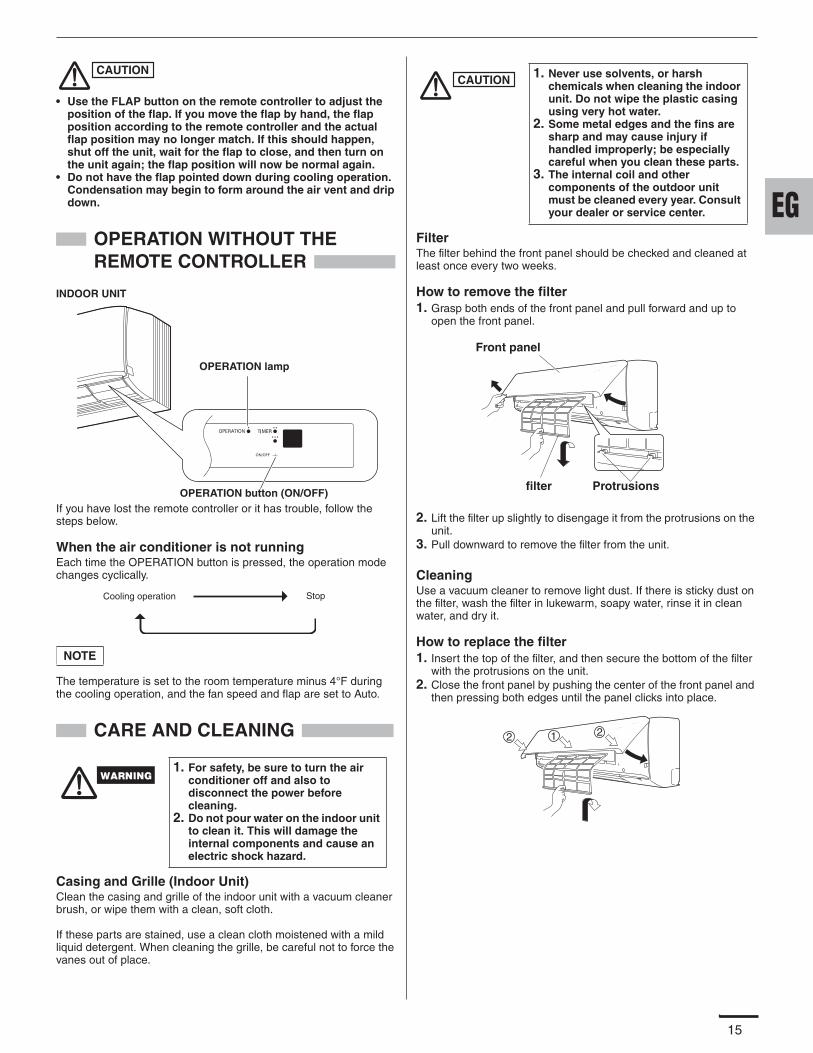
15
• Use the FLAP button on the remote controller to adjust the position of the flap. If you move the flap by hand, the flap position according to the remote controller and the actual flap position may no longer match. If this should happen, shut off the unit, wait for the flap to close, and then turn on the unit again; the flap position will now be normal again.
• Do not have the flap pointed down during cooling operation. Condensation may begin to form around the air vent and drip down.
OPERATION WITHOUT THE REMOTE CONTROLLER
If you have lost the remote controller or it has trouble, follow the steps below.
When the air conditioner is not runningEach time the OPERATION button is pressed, the operation mode changes cyclically.
The temperature is set to the room temperature minus 4°F during the cooling operation, and the fan speed and flap are set to Auto.
CARE AND CLEANING
Casing and Grille (Indoor Unit)Clean the casing and grille of the indoor unit with a vacuum cleaner brush, or wipe them with a clean, soft cloth.
If these parts are stained, use a clean cloth moistened with a mild liquid detergent. When cleaning the grille, be careful not to force the vanes out of place.
FilterThe filter behind the front panel should be checked and cleaned at least once every two weeks.
How to remove the filter1. Grasp both ends of the front panel and pull forward and up to
open the front panel.
2. Lift the filter up slightly to disengage it from the protrusions on the unit.
3. Pull downward to remove the filter from the unit.
CleaningUse a vacuum cleaner to remove light dust. If there is sticky dust on the filter, wash the filter in lukewarm, soapy water, rinse it in clean water, and dry it.
How to replace the filter1. Insert the top of the filter, and then secure the bottom of the filter
with the protrusions on the unit.2. Close the front panel by pushing the center of the front panel and
then pressing both edges until the panel clicks into place.
1. For safety, be sure to turn the air conditioner off and also to disconnect the power before cleaning.
2. Do not pour water on the indoor unit to clean it. This will damage the internal components and cause an electric shock hazard.
CAUTION
INDOOR UNIT
OPERATION button (ON/OFF)
OPERATION lamp
Cooling operation Stop
NOTE
1. Never use solvents, or harsh chemicals when cleaning the indoor unit. Do not wipe the plastic casing using very hot water.
2. Some metal edges and the fins are sharp and may cause injury if handled improperly; be especially careful when you clean these parts.
3. The internal coil and other components of the outdoor unit must be cleaned every year. Consult your dealer or service center.
CAUTION
Protrusions
Front panel
filter
1 22
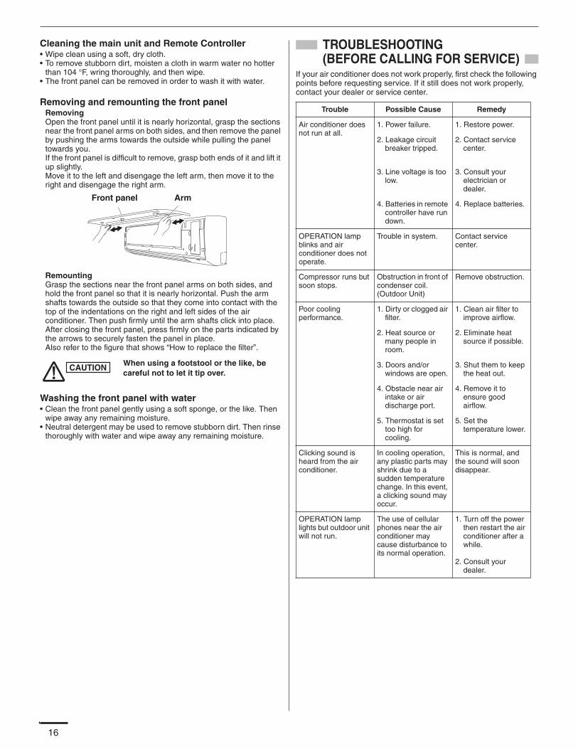
16
Cleaning the main unit and Remote Controller• Wipe clean using a soft, dry cloth.• To remove stubborn dirt, moisten a cloth in warm water no hotter
than 104 °F, wring thoroughly, and then wipe.• The front panel can be removed in order to wash it with water.
Removing and remounting the front panelRemovingOpen the front panel until it is nearly horizontal, grasp the sections near the front panel arms on both sides, and then remove the panel by pushing the arms towards the outside while pulling the panel towards you.If the front panel is difficult to remove, grasp both ends of it and lift it up slightly. Move it to the left and disengage the left arm, then move it to the right and disengage the right arm.
RemountingGrasp the sections near the front panel arms on both sides, and hold the front panel so that it is nearly horizontal. Push the arm shafts towards the outside so that they come into contact with the top of the indentations on the right and left sides of the air conditioner. Then push firmly until the arm shafts click into place. After closing the front panel, press firmly on the parts indicated by the arrows to securely fasten the panel in place.Also refer to the figure that shows “How to replace the filter”.
Washing the front panel with water• Clean the front panel gently using a soft sponge, or the like. Then
wipe away any remaining moisture.• Neutral detergent may be used to remove stubborn dirt. Then rinse
thoroughly with water and wipe away any remaining moisture.
TROUBLESHOOTING (BEFORE CALLING FOR SERVICE)
If your air conditioner does not work properly, first check the following points before requesting service. If it still does not work properly, contact your dealer or service center.
When using a footstool or the like, be careful not to let it tip over.
Front panel Arm
CAUTION
Trouble Possible Cause Remedy
Air conditioner does not run at all.
1. Power failure. 1. Restore power.
2. Leakage circuit breaker tripped.
2. Contact service center.
3. Line voltage is too low.
3. Consult your electrician or dealer.
4. Batteries in remote controller have run down.
4. Replace batteries.
OPERATION lamp blinks and air conditioner does not operate.
Trouble in system. Contact service center.
Compressor runs but soon stops.
Obstruction in front of condenser coil.(Outdoor Unit)
Remove obstruction.
Poor cooling performance.
1. Dirty or clogged air filter.
1. Clean air filter to improve airflow.
2. Heat source or many people in room.
2. Eliminate heat source if possible.
3. Doors and/or windows are open.
3. Shut them to keep the heat out.
4. Obstacle near air intake or air discharge port.
4. Remove it to ensure good airflow.
5. Thermostat is set too high for cooling.
5. Set the temperature lower.
Clicking sound is heard from the air conditioner.
In cooling operation, any plastic parts may shrink due to a sudden temperature change. In this event, a clicking sound may occur.
This is normal, and the sound will soon disappear.
OPERATION lamp lights but outdoor unit will not run.
The use of cellular phones near the air conditioner may cause disturbance to its normal operation.
1. Turn off the power then restart the air conditioner after a while.
2. Consult your dealer.
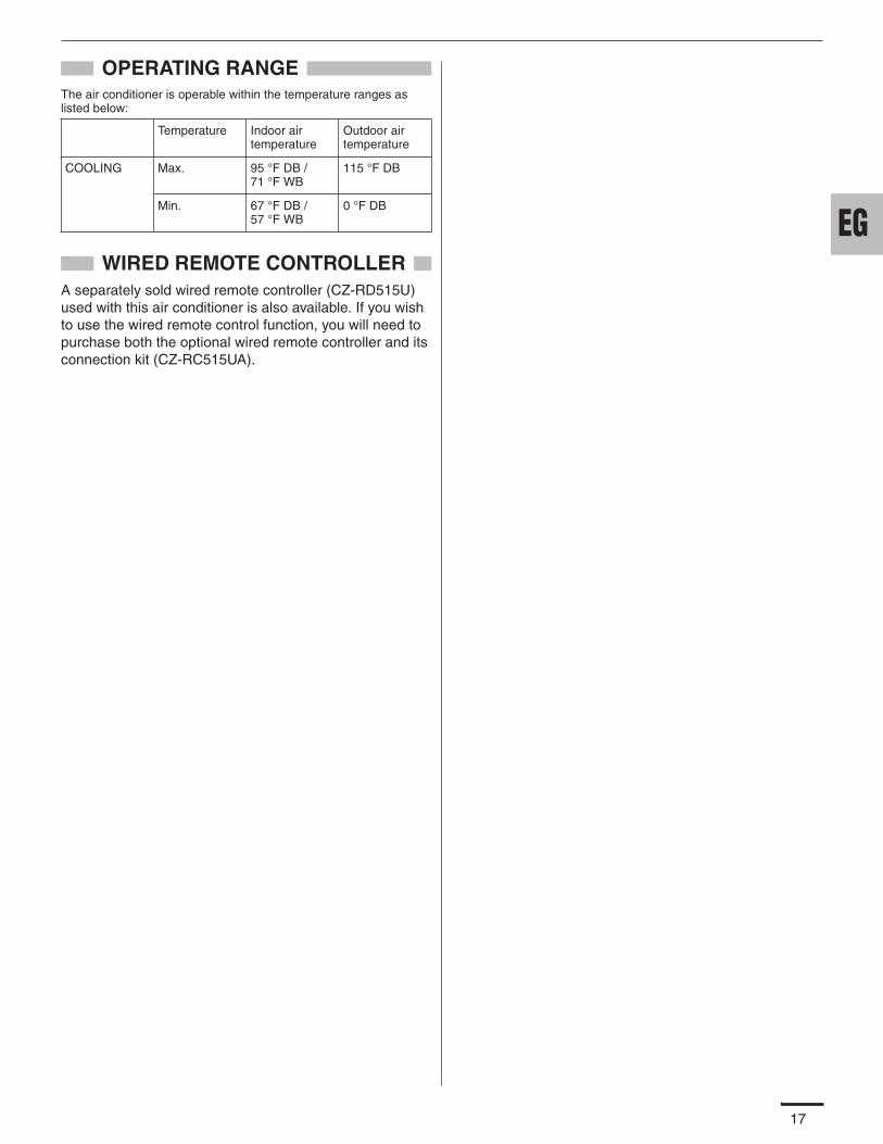
17
OPERATING RANGEThe air conditioner is operable within the temperature ranges as listed below:
WIRED REMOTE CONTROLLERA separately sold wired remote controller (CZ-RD515U) used with this air conditioner is also available. If you wish to use the wired remote control function, you will need to purchase both the optional wired remote controller and its connection kit (CZ-RC515UA).
Temperature Indoor air temperature
Outdoor air temperature
COOLING Max. 95 °F DB / 71 °F WB
115 °F DB
Min. 67 °F DB / 57 °F WB
0 °F DB
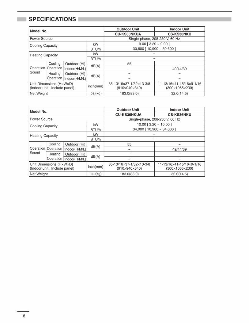
18
SPECIFICATIONS
Model No. Outdoor Unit Indoor UnitCS-KS30NKUCU-KS30NKUA
30,600 [ 10,900 ~ 30,600 ]
55
Single-phase, 208-230 V, 60 Hz9.00 [ 3.20 ~ 9.00 ]
--
---
35-13/16×37-1/32×13-3/8(910×940×340)
-49/44/39
--
Heating Capacity
OperationSound
Unit Dimensions (H×W×D)(Indoor unit : Include panel)
Net Weight
Power Source
Cooling Capacity kWBTU/h
kWBTU/h
inch(mm)
lbs.(kg)
CoolingOperation
Outdoor (Hi)Indoor(H/M/L)Outdoor (Hi)Indoor(H/M/L)
HeatingOperation
dB(A)
dB(A)
183.0(83.0)
11-13/16×41-15/16×9-1/16(300×1065×230)
32.0(14.5)
Model No. Outdoor Unit Indoor UnitCS-KS36NKUCU-KS36NKUA
34,000 [ 10,900 ~ 34,000 ]
55
Single-phase, 208-230 V, 60 Hz10.00 [ 3.20 ~ 10.00 ]
--
--
35-13/16×37-1/32×13-3/8(910×940×340)
-49/44/39
--
Heating Capacity
OperationSound
Unit Dimensions (H×W×D)(Indoor unit : Include panel)
Net Weight
Power Source
Cooling Capacity kWBTU/h
kWBTU/h
inch(mm)
lbs.(kg)
CoolingOperation
Outdoor (Hi)Indoor(H/M/L)Outdoor (Hi)Indoor(H/M/L)
HeatingOperation
dB(A)
dB(A)
183.0(83.0)
11-13/16×41-15/16×9-1/16(300×1065×230)
32.0(14.5)
-

INSTALLATION INSTRUCTIONSAPPENDIX B
CS-KS30NKU + CU-KS30NKUACS-KS36NKU + CU-KS36NKUA
(852-6-4190-586-00-0)
A-2
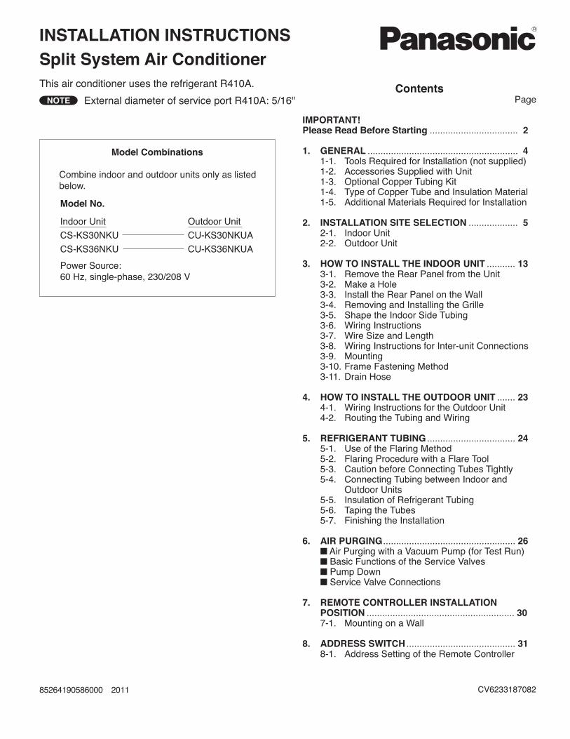
Split System Air ConditionerINSTALLATION INSTRUCTIONS
NOTEContents
Page
IMPORTANT!Please Read Before Starting .................................. 2
1. GENERAL .......................................................... 41-1. Tools Required for Installation (not supplied)1-2. Accessories Supplied with Unit1-3. Optional Copper Tubing Kit1-4. Type of Copper Tube and Insulation Material1-5. Additional Materials Required for Installation
2. INSTALLATION SITE SELECTION ................... 52-1. Indoor Unit2-2. Outdoor Unit
3. HOW TO INSTALL THE INDOOR UNIT ........... 133-1. Remove the Rear Panel from the Unit3-2. Make a Hole3-3. Install the Rear Panel on the Wall3-4. Removing and Installing the Grille3-5. Shape the Indoor Side Tubing3-6. Wiring Instructions3-7. Wire Size and Length3-8. Wiring Instructions for Inter-unit Connections3-9. Mounting3-10. Frame Fastening Method3-11. Drain Hose
4. HOW TO INSTALL THE OUTDOOR UNIT ....... 234-1. Wiring Instructions for the Outdoor Unit4-2. Routing the Tubing and Wiring
5. REFRIGERANT TUBING .................................. 245-1. Use of the Flaring Method5-2. Flaring Procedure with a Flare Tool5-3. Caution before Connecting Tubes Tightly5-4. Connecting Tubing between Indoor and
Outdoor Units5-5. Insulation of Refrigerant Tubing5-6. Taping the Tubes5-7. Finishing the Installation
6. AIR PURGING................................................... 26Air Purging with a Vacuum Pump (for Test Run)Basic Functions of the Service ValvesPump DownService Valve Connections
7. REMOTE CONTROLLER INSTALLATION POSITION ......................................................... 307-1. Mounting on a Wall
8. ADDRESS SWITCH .......................................... 318-1. Address Setting of the Remote Controller
Model Combinations
Combine indoor and outdoor units only as listedbelow.
Model No.
Indoor Unit Outdoor Unit
CS-KS30NKU CU-KS30NKUA
CS-KS36NKU CU-KS36NKUA
Power Source:60 Hz, single-phase, 230/208 V
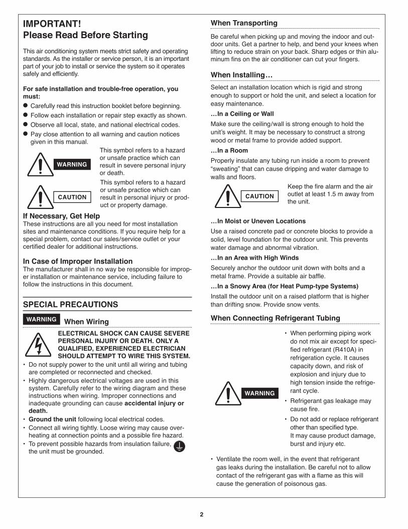
2
IMPORTANT! Please Read Before Starting
This air conditioning system meets strict safety and operatingstandards. As the installer or service person, it is an importantpart of your job to install or service the system so it operatessafely and efficiently.
For safe installation and trouble-free operation, youmust:
Carefully read this instruction booklet before beginning.
Follow each installation or repair step exactly as shown.
Observe all local, state, and national electrical codes.
Pay close attention to all warning and caution noticesgiven in this manual.
This symbol refers to a hazardor unsafe practice which canresult in severe personal injuryor death.
This symbol refers to a hazardor unsafe practice which canresult in personal injury or prod-uct or property damage.
If Necessary, Get HelpThese instructions are all you need for most installationsites and maintenance conditions. If you require help for aspecial problem, contact our sales/service outlet or yourcertified dealer for additional instructions.
In Case of Improper InstallationThe manufacturer shall in no way be responsible for improp-er installation or maintenance service, including failure tofollow the instructions in this document.
SPECIAL PRECAUTIONS
When Wiring
ELECTRICAL SHOCK CAN CAUSE SEVEREPERSONAL INJURY OR DEATH. ONLY AQUALIFIED, EXPERIENCED ELECTRICIANSHOULD ATTEMPT TO WIRE THIS SYSTEM.
are completed or reconnected and checked.
system. Carefully refer to the wiring diagram and theseinstructions when wiring. Improper connections andinadequate grounding can cause accidental injury ordeath.
following local electrical codes.
heating at connection points and a possible fire hazard.
the unit must be grounded.
When Transporting
Be careful when picking up and moving the indoor and out-door units. Get a partner to help, and bend your knees whenlifting to reduce strain on your back. Sharp edges or thin alu-minum fins on the air conditioner can cut your fingers.
When Installing…
Select an installation location which is rigid and strongenough to support or hold the unit, and select a location foreasy maintenance.
…In a Ceiling or Wall
Make sure the ceiling/wall is strong enough to hold theunit’s weight. It may be necessary to construct a strongwood or metal frame to provide added support.
…In a Room
Properly insulate any tubing run inside a room to prevent“sweating” that can cause dripping and water damage towalls and floors.
Keep the fire alarm and the airoutlet at least 1.5 m away fromthe unit.
…In Moist or Uneven Locations
Use a raised concrete pad or concrete blocks to provide asolid, level foundation for the outdoor unit. This preventswater damage and abnormal vibration.
…In an Area with High Winds
Securely anchor the outdoor unit down with bolts and ametal frame. Provide a suitable air baffle.
…In a Snowy Area (for Heat Pump-type Systems)
Install the outdoor unit on a raised platform that is higherthan drifting snow. Provide snow vents.
When Connecting Refrigerant Tubing
gas leaks during the installation. Be careful not to allow contact of the refrigerant gas with a flame as this willcause the generation of poisonous gas.
WARNING
WARNING
WARNING
CAUTION CAUTION
piping workdo not mix air except for speci-fied refrigerant (R410A) inrefrigeration cycle. It causescapacity down, and risk ofexplosion and injury due tohigh tension inside the refrige-rant cycle.
cause fire.
other than specified type.It may cause product damage,burst and injury etc.
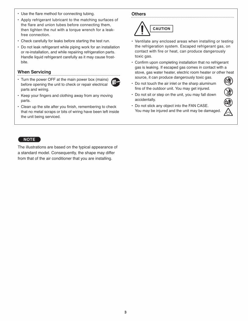
3
the flare and union tubes before connecting them,then tighten the nut with a torque wrench for a leak-free connection.
or re-installation, and while repairing refrigeration parts.Handle liquid refrigerant carefully as it may cause frost-bite.
When Servicing
before opening the unit to check or repair electricalparts and wiring.
parts.
that no metal scraps or bits of wiring have been left insidethe unit being serviced.
Others
the refrigeration system. Escaped refrigerant gas, oncontact with fire or heat, can produce dangerouslytoxic gas.
gas is leaking. If escaped gas comes in contact with astove, gas water heater, electric room heater or other heatsource, it can produce dangerously toxic gas.
fins of the outdoor unit. You may get injured.
accidentally.
You may be injured and the unit may be damaged.
CAUTION
The illustrations are based on the typical appearance ofa standard model. Consequently, the shape may differfrom that of the air conditioner that you are installing.
NOTE
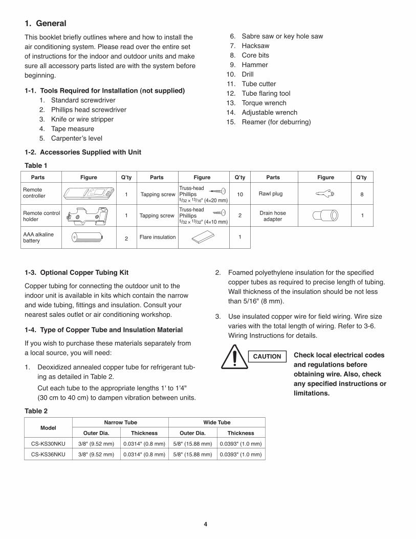
4
1. General
This booklet briefly outlines where and how to install theair conditioning system. Please read over the entire setof instructions for the indoor and outdoor units and makesure all accessory parts listed are with the system beforebeginning.
1-1. Tools Required for Installation (not supplied)1. Standard screwdriver2. Phillips head screwdriver3. Knife or wire stripper4. Tape measure5. Carpenter’s level
6. Sabre saw or key hole saw7. Hacksaw8. Core bits9. Hammer
10. Drill11. Tube cutter12. Tube flaring tool13. Torque wrench14. Adjustable wrench15. Reamer (for deburring)
1-2. Accessories Supplied with Unit
Table 1
1-3. Optional Copper Tubing Kit
Copper tubing for connecting the outdoor unit to theindoor unit is available in kits which contain the narrowand wide tubing, fittings and insulation. Consult yournearest sales outlet or air conditioning workshop.
1-4. Type of Copper Tube and Insulation Material
If you wish to purchase these materials separately froma local source, you will need:
1. Deoxidized annealed copper tube for refrigerant tub-ing as detailed in Table 2.
Cut each tube to the appropriate lengths 1' to 1'4"(30 cm to 40 cm) to dampen vibration between units.
Table 2
2. Foamed polyethylene insulation for the specifiedcopper tubes as required to precise length of tubing.Wall thickness of the insulation should be not lessthan 5/16" (8 mm).
3. Use insulated copper wire for field wiring. Wire sizevaries with the total length of wiring. Refer to 3-6.Wiring Instructions for details.
Parts Figure Q’ty Parts Figure Q’ty
× ×
× ×
Parts Figure Q’ty
CAUTION Check local electrical codesand regulations beforeobtaining wire. Also, checkany specified instructions orlimitations.
ModelNarrow Tube Wide Tube
Outer Dia. Thickness Outer Dia. Thickness
CS-KS30NKU 3/8" (9.52 mm) 0.0314" (0.8 mm) 5/8" (15.88 mm) 0.0393" (1.0 mm)
CS-KS36NKU 3/8" (9.52 mm) 0.0314" (0.8 mm) 5/8" (15.88 mm) 0.0393" (1.0 mm)
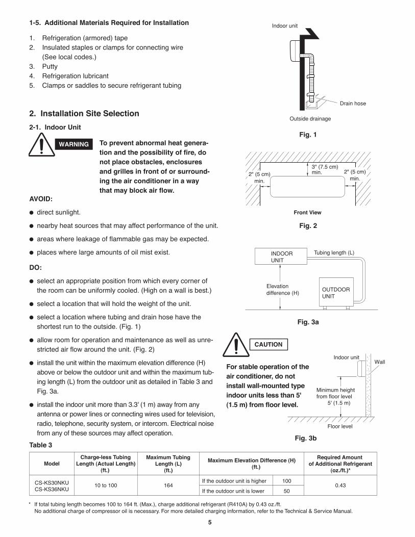
5
1-5. Additional Materials Required for Installation
1. Refrigeration (armored) tape2. Insulated staples or clamps for connecting wire
(See local codes.)3. Putty4. Refrigeration lubricant5. Clamps or saddles to secure refrigerant tubing
2. Installation Site Selection
2-1. Indoor Unit
AVOID:
direct sunlight.
nearby heat sources that may affect performance of the unit.
areas where leakage of flammable gas may be expected.
places where large amounts of oil mist exist.
DO:
select an appropriate position from which every corner of the room can be uniformly cooled. (High on a wall is best.)
select a location that will hold the weight of the unit.
select a location where tubing and drain hose have theshortest run to the outside. (Fig. 1)
allow room for operation and maintenance as well as unre-stricted air flow around the unit. (Fig. 2)
install the unit within the maximum elevation difference (H)above or below the outdoor unit and within the maximum tub-ing length (L) from the outdoor unit as detailed in Table 3 andFig. 3a.
install the indoor unit more than 3.3' (1 m) away from anyantenna or power lines or connecting wires used for television,radio, telephone, security system, or intercom. Electrical noisefrom any of these sources may affect operation.
Drain hose
Indoor unit
Outside drainage
Fig. 1
Front View
Fig. 2
INDOORUNIT
Tubing length (L)
OUTDOORUNIT
Elevationdifference (H)
Fig. 3a
WARNING To prevent abnormal heat genera-tion and the possibility of fire, donot place obstacles, enclosuresand grilles in front of or surround-ing the air conditioner in a waythat may block air flow.
Indoor unit
Floor level
Wall
Minimum height from floor level
5' (1.5 m)
Fig. 3b
For stable operation of theair conditioner, do notinstall wall-mounted typeindoor units less than 5'(1.5 m) from floor level.
CAUTION
Table 3
* If total tubing length becomes 100 to 164 ft. (Max.), charge additional refr igerant (R410A) b y 0.43 oz./ft. No additional charge of compressor oil is necessar y. F or more detailed charging inf ormation, ref er to the T echnical & Ser vice Ma nual.
Model
16410 to 100 0.43
Charge-less Tubing Length (Actual Length)
(ft.)
Maximum Tubing Length (L)
(ft.)
Maximum Elevation Difference (H) (ft.)
CS-KS30NKUCS-KS36NKU
Required Amount of Additional Refrigerant
(oz./ft.)*
If the outdoor unit is higher
If the outdoor unit is lower
100
50
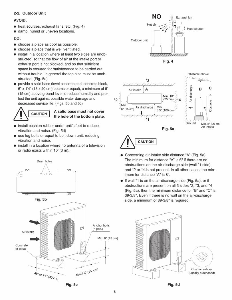
6
Concerning air-intake side distance “A” (Fig. 5a)The minimum for distance “A” is 6" if there are noobstructions on the air-discharge side (wall *1 side)and *2 or *4 is not present. In all other cases, the min-imum for distance “A” is 8".
If wall *1 is on the air-discharge side (Fig. 5a), or ifobstructions are present on all 3 sides *2, *3, and *4(Fig. 5a), then the minimum distance for “B” and “C” is39-3/8". Even if there is no wall on the air-dischargeside, a minimum of 39-3/8" is required.
Fig. 5c
2-2. Outdoor Unit
AVOID:
heat sources, exhaust fans, etc. (Fig. 4)damp, humid or uneven locations.
DO:
choose a place as cool as possible.choose a place that is well ventilated.install in a location where at least two sides are unob-structed, so that the flow of air at the intake port orexhaust port is not blocked, and so that sufficientspace is ensured for maintenance to be carried outwithout trouble. In general the top also must be unob-structed. (Fig. 5a)provide a solid base (level concrete pad, concrete block,6" x 1'4" (15 x 40 cm) beams or equal), a minimum of 6"(15 cm) above ground level to reduce humidity and pro-tect the unit against possible water damage anddecreased service life. (Figs. 5b and 5c)
install cushion rubber under unit’s feet to reducevibration and noise. (Fig. 5d)use lug bolts or equal to bolt down unit, reducingvibration and noise.install in a location where no antenna of a televisionor radio exists within 10' (3 m).
Outdoor unit
Hot airHeat source
Exhaust fanNO
Fig. 4
*1
*2
*3
*4
A B C
Fig. 5d
Fig. 5a
Fig. 5b
CAUTION
CAUTION
A solid base must not coverthe hole of the bottom plate.
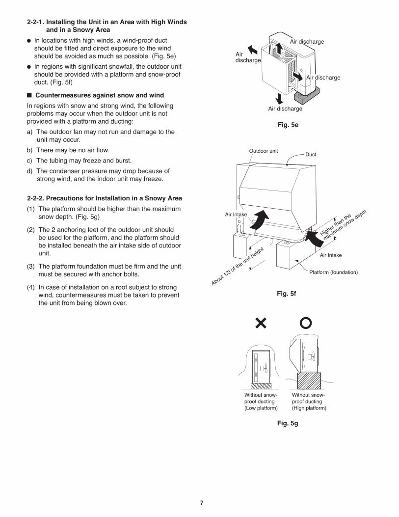
7
Fig. 5e
Fig. 5f
Fig. 5g
2-2-1. Installing the Unit in an Area with High Winds and in a Snowy Area
Countermeasures against snow and wind
2-2-2. Precautions for Installation in a Snowy Area
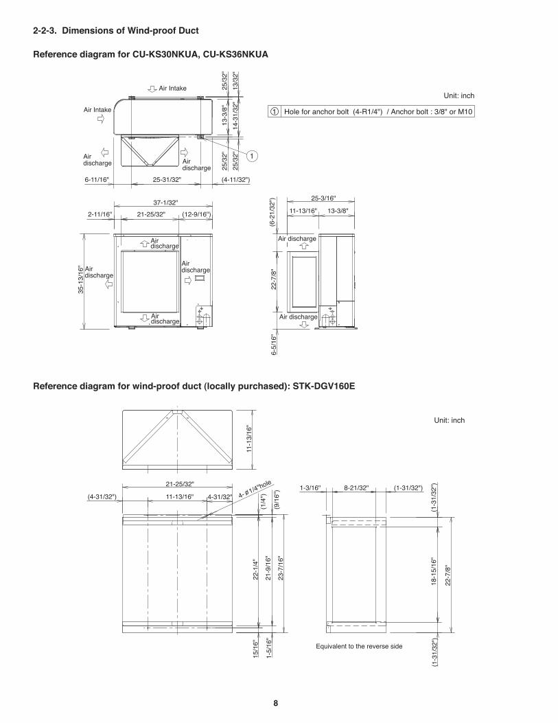
8
11-13/16" 13-3/8"
25-3/16"
22-7
/8"
(6-2
1/32
")6-
5/16
"
21-25/32" (12-9/16")2-11/16"
35-1
3/16
"
37-1/32"
Airdischarge
Airdischarge
Airdischarge
Hole for anchor bolt (4-R1/4") / Anchor bolt : 3/8" or M101
Airdischarge
Air discharge
25-31/32"6-11/16"
13-3
/8"
25/3
2"25
/32"
14-3
1/32
"13
/32"
25/3
2"
Air Intake
Airdischarge
Unit: inch
Air
Air Intake
1
(4-11/32")
discharge
Air discharge
2-2-3. Dimensions of Wind-proof Duct
Reference diagram for CU-KS30NKUA, CU-KS36NKUA
(9/1
6")
21-9
/16"
(1/4
")22
-1/4
"
23-7
/16"
(4-31/32") 4-31/32"
21-25/32"
11-13/16"
11-1
3/16
"
1-5/
16"
15/1
6"
18-1
5/16
"(1
-31/
32")
(1-3
1/32
")
(1-31/32")8-21/32"1-3/16"
22-7
/8"
Equivalent to the reverse side
Unit: inch
4- 1/4"hole
Reference diagram for wind-proof duct (locally purchased): STK-DGV160E
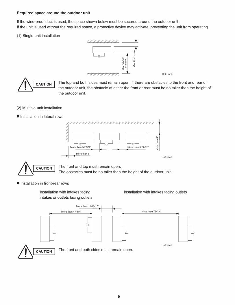
9
Required space around the outdoor unit
CAUTION
CAUTION
CAUTION
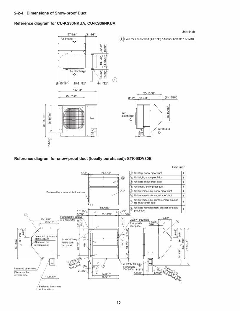
10
25-13/32"
3/32" 13-3/8" (11-15/16")
16-1
5/16
"
Air Intake
Airdischarge
39-1/4"
27-7/32"
7-1/
32"
35-1
5/16
"
28-1
5/16
"
27-5/8" (11-5/8")
Air Intake
13/3
2"14
-31/
32"
25/3
2"
25/3
2"
25/3
2"13
-3/8
"
4-11/32"1
(8-15/16") 25-31/32"
Air discharge
1
Unit: inch
Hole for anchor bolt (4-R1/4") / Anchor bolt: 3/8" or M10
2-2-4. Dimensions of Snow-proof Duct
Reference diagram for CU-KS30NKUA, CU-KS36NKUA
7
3
4
6
8
2
11
2
3
4
5
6
7
8
1
1
1
1
1
1
1
Unit: inch
Unit top, snow-proof duct
Unit right, snow-proof duct
Unit left, snow-proof duct
Unit front, snow-proof duct
Unit reverse side, snow-proof duct
Unit reverse side, snow-proof duct
Unit reverse side, reinforcement bracket for snow-proof duct
Unit left, reinforcement bracket for snow-proof duct
Fastened by screws at 14 locations
Fastened by screws at 3 locations
Fixing with
front panel2- 9/32"hole
2- 9/32"hole2- 9/32"hole
2- 9/32"hole
9/32"X13/32"hole
15-11/32"
Fastened by screws
(Same on the reverse side)
Fastened by screws at 2 locations
28-1
3/16
"16
-15/
16"
9-1/
8"
31/3
2"
2-7/32"24-3/16"28-3/16"
23 Fixing with rear panel
5/8"
6-1/
32"
28-3/16"
1-15/16"20-13/32"
5/16"
5-13
/32" 34
-23/
32"
11-7/8"
28-/
13/1
6"
16-1
5/16
"
9-1/
8"
4-1/32"Fixing with rear panel
Unit anchor holes
(Unit fixed bottom plate)
9-7/
32"
13-7
/8"
5-1/
8"
4-11/32"
1-9/
16"
5-7/8"
25/3
2"
4-27
/32"
20-7
/8"
3-27/32"
3-15/16"
4-23/32"
25-13/32"17-9/16"
Fastened by screws at 2 locations(Same on the reverse side)
Fixing with top panel
1/16" 27-9/16"
5
1
Reference diagram for snow-proof duct (locally purchased): STK-BDV80E
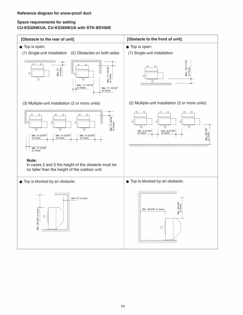
11
Reference diagram for snow-proof duct
Space requirements for setting CU-KS30NKUA, CU-KS36NKUA with STK-BDV80E
[Obstacle to the front of unit] [Obstacle to the rear of unit]
Note:
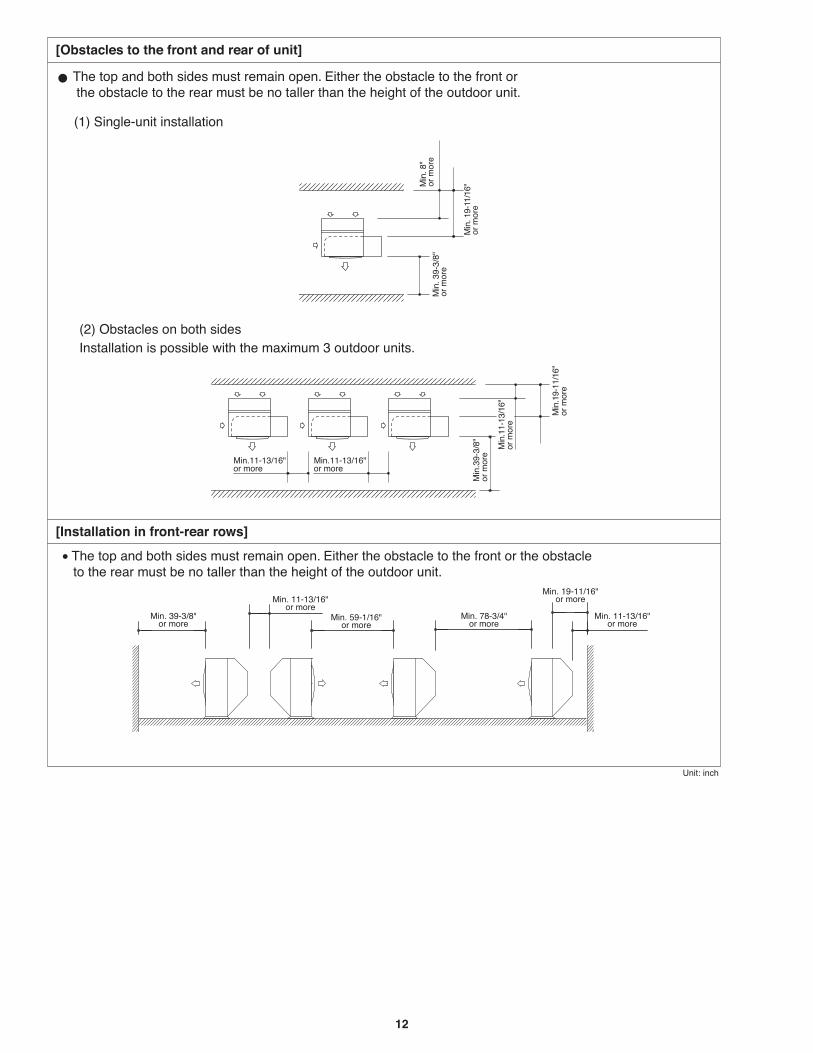
12
[Installation in front-rear rows]
[Obstacles to the front and rear of unit]
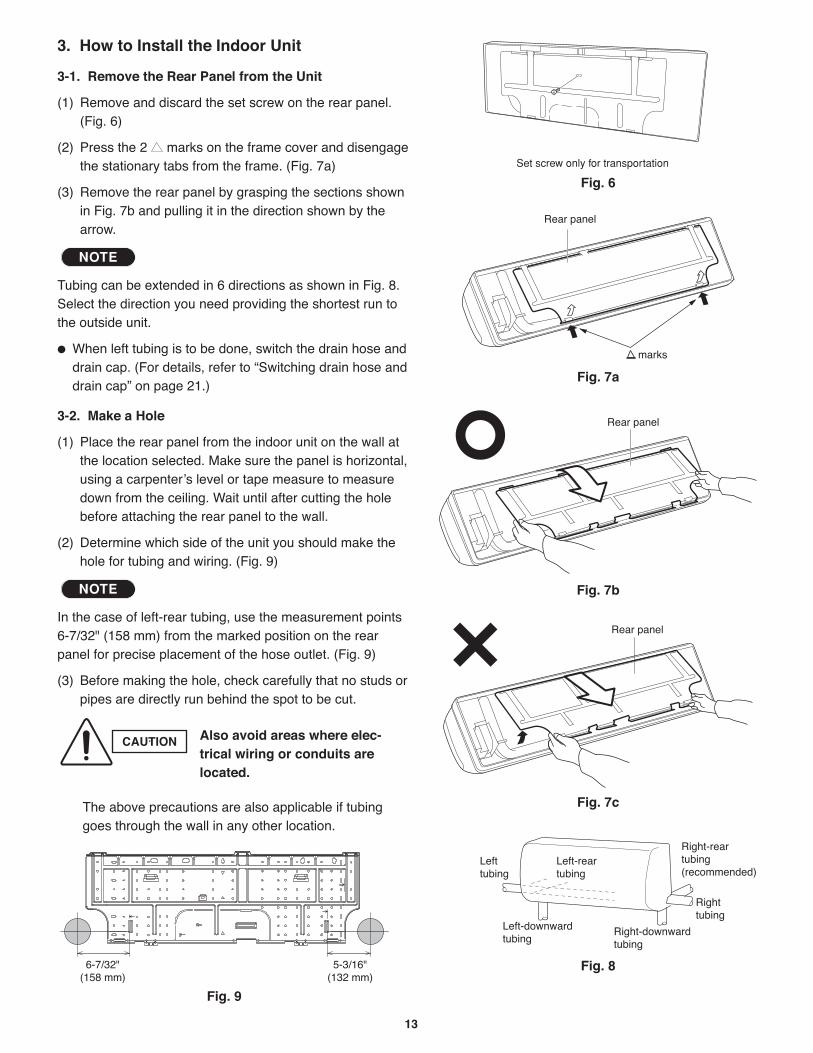
13
Rear panel
Fig. 7c
Rear panel
Fig. 7b
Set screw only for transportation
Fig. 6
Rear panel
marks
Fig. 7a
Fig. 8
3. How to Install the Indoor Unit
3-1. Remove the Rear Panel from the Unit
(1) Remove and discard the set screw on the rear panel.(Fig. 6)
(2) Press the 2 marks on the frame cover and disengagethe stationary tabs from the frame. (Fig. 7a)
(3) Remove the rear panel by grasping the sections shownin Fig. 7b and pulling it in the direction shown by thearrow.
Tubing can be extended in 6 directions as shown in Fig. 8.Select the direction you need providing the shortest run tothe outside unit.
When left tubing is to be done, switch the drain hose anddrain cap. (For details, refer to “Switching drain hose anddrain cap” on page 21.)
3-2. Make a Hole
(1) Place the rear panel from the indoor unit on the wall atthe location selected. Make sure the panel is horizontal,using a carpenter’s level or tape measure to measuredown from the ceiling. Wait until after cutting the holebefore attaching the rear panel to the wall.
(2) Determine which side of the unit you should make thehole for tubing and wiring. (Fig. 9)
In the case of left-rear tubing, use the measurement points6-7/32" (158 mm) from the marked position on the rearpanel for precise placement of the hose outlet. (Fig. 9)
(3) Before making the hole, check carefully that no studs orpipes are directly run behind the spot to be cut.
The above precautions are also applicable if tubinggoes through the wall in any other location.
NOTE
NOTE
Fig. 9
CAUTION Also avoid areas where elec-trical wiring or conduits arelocated.
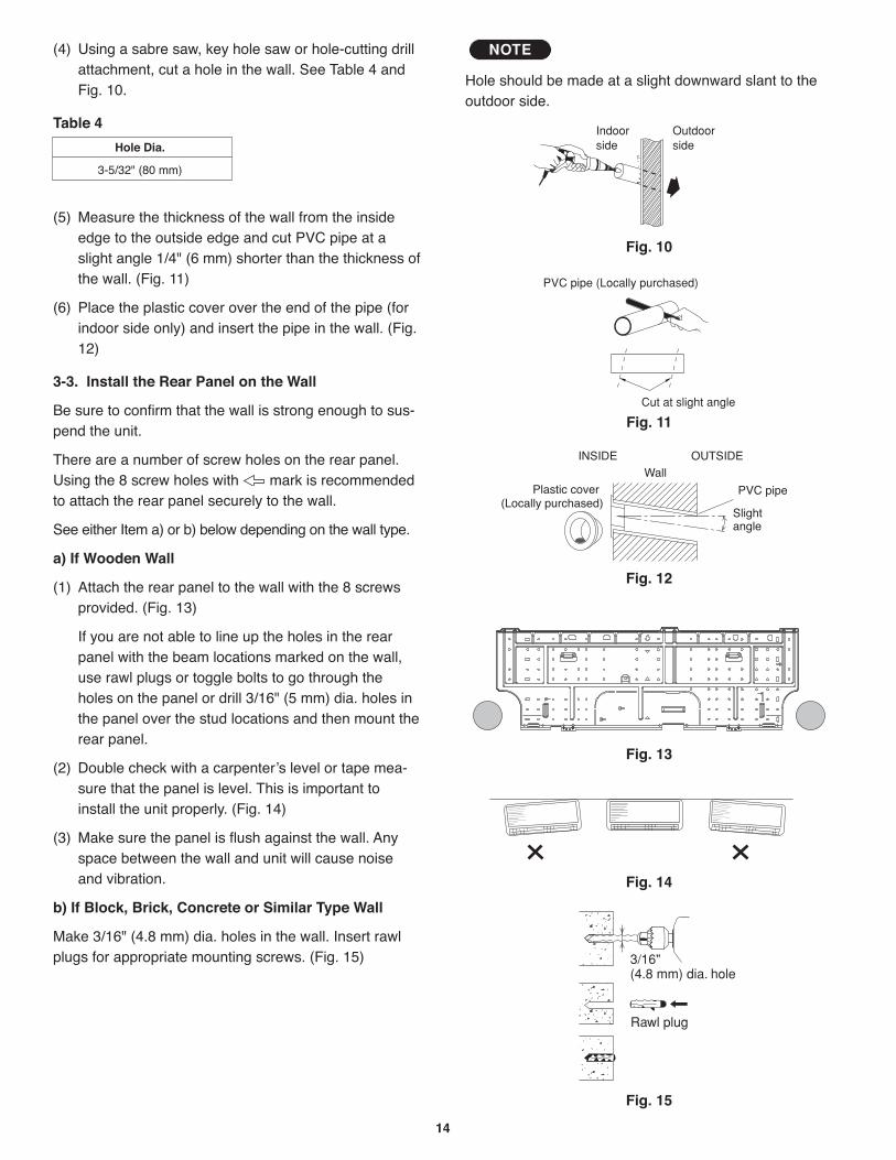
14
Indoorside
Outdoorside
Hole should be made at a slight downward slant to theoutdoor side.
NOTE
Fig. 10
Plastic cover
INSIDE OUTSIDEWall
Slightangle
PVC pipe(Locally purchased)
Fig. 12
PVC pipe (Locally purchased)
Cut at slight angle
Fig. 11
(4) Using a sabre saw, key hole saw or hole-cutting drillattachment, cut a hole in the wall. See Table 4 andFig. 10.
Table 4
(5) Measure the thickness of the wall from the insideedge to the outside edge and cut PVC pipe at aslight angle 1/4" (6 mm) shorter than the thickness ofthe wall. (Fig. 11)
(6) Place the plastic cover over the end of the pipe (forindoor side only) and insert the pipe in the wall. (Fig.12)
3-3. Install the Rear Panel on the Wall
Be sure to confirm that the wall is strong enough to sus-pend the unit.
There are a number of screw holes on the rear panel.Using the 8 screw holes with mark is recommendedto attach the rear panel securely to the wall.
See either Item a) or b) below depending on the wall type.
a) If Wooden Wall
(1) Attach the rear panel to the wall with the 8 screwsprovided. (Fig. 13)
If you are not able to line up the holes in the rearpanel with the beam locations marked on the wall,use rawl plugs or toggle bolts to go through theholes on the panel or drill 3/16" (5 mm) dia. holes inthe panel over the stud locations and then mount therear panel.
(2) Double check with a carpenter’s level or tape mea-sure that the panel is level. This is important to install the unit properly. (Fig. 14)
(3) Make sure the panel is flush against the wall. Anyspace between the wall and unit will cause noiseand vibration.
b) If Block, Brick, Concrete or Similar Type Wall
Make 3/16" (4.8 mm) dia. holes in the wall. Insert rawlplugs for appropriate mounting screws. (Fig. 15)
Hole Dia.
3-5/32" (80 mm)
Fig. 13
Fig. 14
3/16"(4.8 mm) dia. hole
Rawl plug
Fig. 15
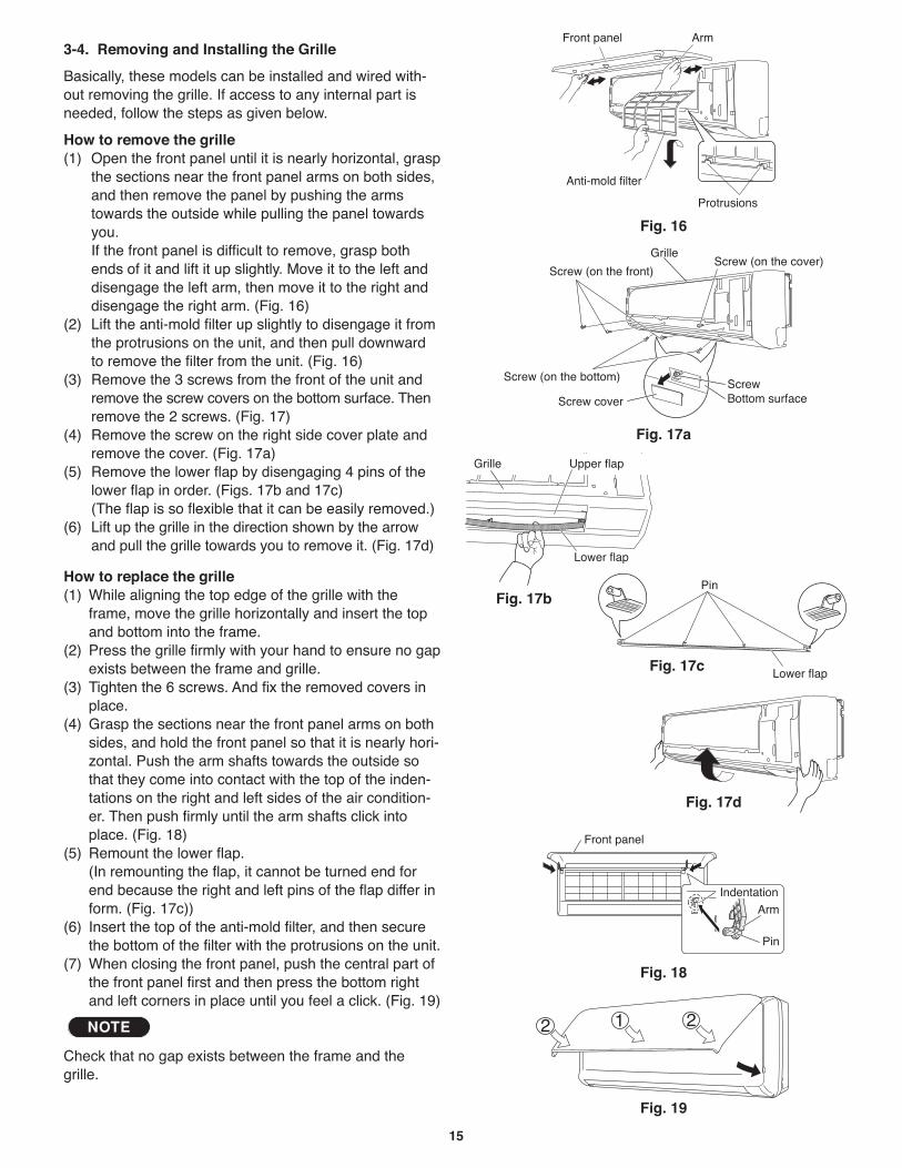
15
3-4. Removing and Installing the Grille
Basically, these models can be installed and wired with-out removing the grille. If access to any internal part isneeded, follow the steps as given below.
How to remove the grille(1) Open the front panel until it is nearly horizontal, grasp
the sections near the front panel arms on both sides,and then remove the panel by pushing the armstowards the outside while pulling the panel towardsyou.If the front panel is difficult to remove, grasp bothends of it and lift it up slightly. Move it to the left anddisengage the left arm, then move it to the right anddisengage the right arm. (Fig. 16)
(2) Lift the anti-mold filter up slightly to disengage it fromthe protrusions on the unit, and then pull downwardto remove the filter from the unit. (Fig. 16)
(3) Remove the 3 screws from the front of the unit andremove the screw covers on the bottom surface. Thenremove the 2 screws. (Fig. 17)
(4) Remove the screw on the right side cover plate andremove the cover. (Fig. 17a)
(5) Remove the lower flap by disengaging 4 pins of thelower flap in order. (Figs. 17b and 17c)(The flap is so flexible that it can be easily removed.)
(6) Lift up the grille in the direction shown by the arrowand pull the grille towards you to remove it. (Fig. 17d)
How to replace the grille(1) While aligning the top edge of the grille with the
frame, move the grille horizontally and insert the topand bottom into the frame.
(2) Press the grille firmly with your hand to ensure no gapexists between the frame and grille.
(3) Tighten the 6 screws. And fix the removed covers inplace.
(4) Grasp the sections near the front panel arms on bothsides, and hold the front panel so that it is nearly hori-zontal. Push the arm shafts towards the outside sothat they come into contact with the top of the inden-tations on the right and left sides of the air condition-er. Then push firmly until the arm shafts click intoplace. (Fig. 18)
(5) Remount the lower flap.(In remounting the flap, it cannot be turned end forend because the right and left pins of the flap differ inform. (Fig. 17c))
(6) Insert the top of the anti-mold filter, and then securethe bottom of the filter with the protrusions on the unit.
(7) When closing the front panel, push the central part ofthe front panel first and then press the bottom rightand left corners in place until you feel a click. (Fig. 19)
Check that no gap exists between the frame and thegrille.
NOTE
Grille
Screw cover
ScrewBottom surface
Screw (on the front)Screw (on the cover)
Screw (on the bottom)
Anti-mold filter
Front panel Arm
Protrusions
Fig. 16
Fig. 17a
Fig. 18
Fig. 19
Grille Upper flap
Lower flap
Fig. 17b
Lower flap
Pin
Fig. 17c
Fig. 17d
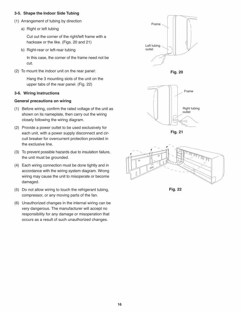
16
3-5. Shape the Indoor Side Tubing
(1) Arrangement of tubing by direction
a) Right or left tubing
Cut out the corner of the right/left frame with ahacksaw or the like. (Figs. 20 and 21)
b) Right-rear or left-rear tubing
In this case, the corner of the frame need not becut.
(2) To mount the indoor unit on the rear panel:
Hang the 3 mounting slots of the unit on theupper tabs of the rear panel. (Fig. 22)
3-6. Wiring Instructions
General precautions on wiring
(1) Before wiring, confirm the rated voltage of the unit asshown on its nameplate, then carry out the wiringclosely following the wiring diagram.
(2) Provide a power outlet to be used exclusively foreach unit, with a power supply disconnect and cir-cuit breaker for overcurrent protection provided inthe exclusive line.
(3) To prevent possible hazards due to insulation failure,the unit must be grounded.
(4) Each wiring connection must be done tightly and inaccordance with the wiring system diagram. Wrongwiring may cause the unit to misoperate or becomedamaged.
(5) Do not allow wiring to touch the refrigerant tubing,compressor, or any moving parts of the fan.
(6) Unauthorized changes in the internal wiring can bevery dangerous. The manufacturer will accept noresponsibility for any damage or misoperation thatoccurs as a result of such unauthorized changes.
Frame
Right tubingoutlet
Fig. 21
Fig. 22
Fig. 20
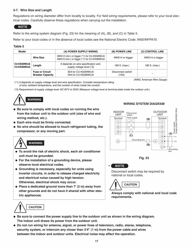
17
3-7. Wire Size and Length
Regulations on wiring diameter differ from locality to locality. For field wiring requirements, please refer to your local elec-trical codes. Carefully observe these regulations when carrying out the installation.
Refer to the wiring system diagram (Fig. 23) for the meaning of (A), (B), and (C) in Table 5.
Refer to your local codes or in the absence of local codes see the National Electric Code: ANSI/NFPA70.
NOTE
Fig. 23
WIRING SYSTEM DIAGRAM
Be sure to comply with local codes on running the wirefrom the indoor unit to the outdoor unit (size of wire andwiring method, etc.).Each wire must be firmly connected.No wire should be allowed to touch refrigerant tubing, thecompressor, or any moving part.
(A)
(B)
(C)
(B)
CAUTION
Be sure to connect the power supply line to the outdoor unit as shown in the wiring diagram.The indoor unit draws its power from the outdoor unit.Do not run wiring for antenna, signal, or power lines of television, radio, stereo, telephone,security system, or intercom any closer than 3'4" (1 m) from the power cable and wiresbetween the indoor and outdoor units. Electrical noise may affect the operation.
To avoid the risk of electric shock, each air conditionerunit must be grounded.For the installation of a grounding device, pleaseobserve local electrical codes.Grounding is necessary, especially for units usinginverter circuits, in order to release charged electricityand electrical noise caused by high tension. Otherwise, electrical shock may occur.Place a dedicated ground more than 7' (2 m) away fromother grounds and do not have it shared with other elec-tric appliances.
WARNING
Table 5
WARNING
*Disconnect switch may be required bynational or local codes.
Always comply with national and local coderequirements.
CAUTION
NOTE
Wire Size
Fuse or CircuitBreaker Capacity
LengthCU-KS30NKUACU-KS36NKUA
It depends on wire specification and supply voltage level (*2)
35A for CU-KS30NKUA45A for CU-KS36NKUA
AWG12 (min.) or bigger (*1) for CU-KS30NKUAAWG10 (min.) or bigger (*1) for CU-KS36NKUA
AWG14 or bigger
180 ft. (max.)
Disconnect switch(15A)
AWG14 or bigger
180 ft. (max.)
(AWG: American Wire Gauge)
Model (A) POWER SUPPLY WIRING (B) POWER LINE (C) CONTROL LINE
-
(*1) It depends on supply voltage level and wire specification. Consider temperature rating of wire, ambient temperature, and the number of wires inside the conduit.
(*2) Requirement of supply voltage level: AC187V to 253V (Measure voltage level at terminal plate inside the outdoor unit.)
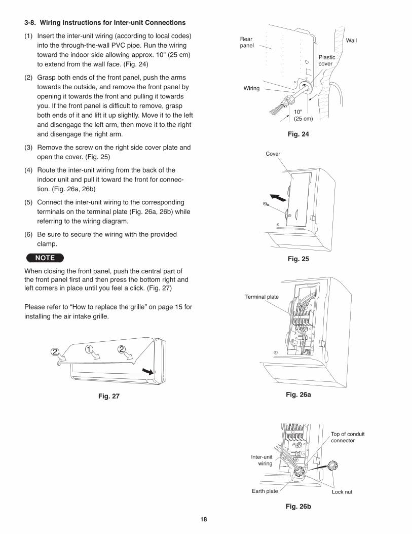
18
3-8. Wiring Instructions for Inter-unit Connections
(1) Insert the inter-unit wiring (according to local codes)into the through-the-wall PVC pipe. Run the wiringtoward the indoor side allowing approx. 10" (25 cm)to extend from the wall face. (Fig. 24)
(2) Grasp both ends of the front panel, push the armstowards the outside, and remove the front panel byopening it towards the front and pulling it towardsyou. If the front panel is difficult to remove, graspboth ends of it and lift it up slightly. Move it to the leftand disengage the left arm, then move it to the rightand disengage the right arm.
(3) Remove the screw on the right side cover plate andopen the cover. (Fig. 25)
(4) Route the inter-unit wiring from the back of theindoor unit and pull it toward the front for connec-tion. (Fig. 26a, 26b)
(5) Connect the inter-unit wiring to the correspondingterminals on the terminal plate (Fig. 26a, 26b) whilereferring to the wiring diagram.
(6) Be sure to secure the wiring with the providedclamp.
When closing the front panel, push the central part ofthe front panel first and then press the bottom right andleft corners in place until you feel a click. (Fig. 27)
Please refer to “How to replace the grille” on page 15 forinstalling the air intake grille.
NOTE
Fig. 24
Cover
Fig. 25
Fig. 26a
Fig. 26b
Fig. 27
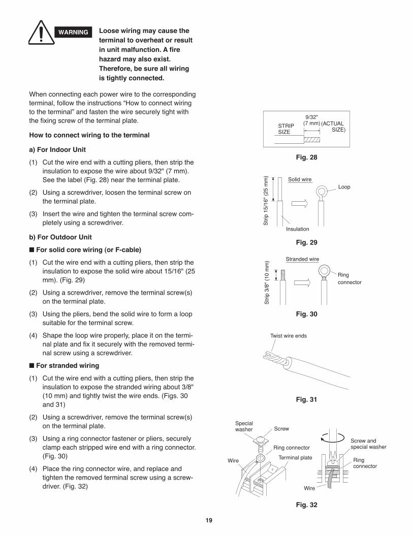
19
When connecting each power wire to the correspondingterminal, follow the instructions “How to connect wiringto the terminal” and fasten the wire securely tight withthe fixing screw of the terminal plate.
How to connect wiring to the terminal
a) For Indoor Unit
(1) Cut the wire end with a cutting pliers, then strip theinsulation to expose the wire about 9/32" (7 mm).See the label (Fig. 28) near the terminal plate.
(2) Using a screwdriver, loosen the terminal screw onthe terminal plate.
(3) Insert the wire and tighten the terminal screw com-pletely using a screwdriver.
b) For Outdoor Unit
For solid core wiring (or F-cable)
(1) Cut the wire end with a cutting pliers, then strip theinsulation to expose the solid wire about 15/16" (25mm). (Fig. 29)
(2) Using a screwdriver, remove the terminal screw(s)on the terminal plate.
(3) Using the pliers, bend the solid wire to form a loopsuitable for the terminal screw.
(4) Shape the loop wire properly, place it on the termi-nal plate and fix it securely with the removed termi-nal screw using a screwdriver.
For stranded wiring
(1) Cut the wire end with a cutting pliers, then strip theinsulation to expose the stranded wiring about 3/8"(10 mm) and tightly twist the wire ends. (Figs. 30and 31)
(2) Using a screwdriver, remove the terminal screw(s)on the terminal plate.
(3) Using a ring connector fastener or pliers, securelyclamp each stripped wire end with a ring connector.(Fig. 30)
(4) Place the ring connector wire, and replace andtighten the removed terminal screw using a screw-driver. (Fig. 32)
Solid wireLoop
Insulation
Str
ip 1
5/16
" (2
5 m
m)
Fig. 29
STRIPSIZE
9/32"(7 mm) (ACTUAL
SIZE)
Fig. 28
Stranded wire
Ringconnector
Str
ip 3
/8"
(10
mm
)
Fig. 30
Screw
Ring connector
Terminal plateWire
Specialwasher
Fig. 32
Screw and special washer
Ringconnector
Wire
WARNING Loose wiring may cause theterminal to overheat or resultin unit malfunction. A firehazard may also exist.Therefore, be sure all wiringis tightly connected.
Twist wire ends
Fig. 31
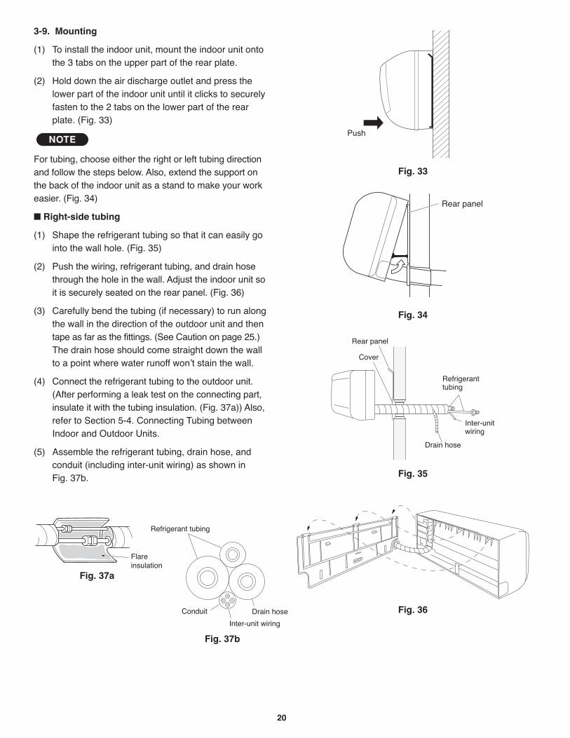
20
3-9. Mounting
(1) To install the indoor unit, mount the indoor unit ontothe 3 tabs on the upper part of the rear plate.
(2) Hold down the air discharge outlet and press thelower part of the indoor unit until it clicks to securelyfasten to the 2 tabs on the lower part of the rearplate. (Fig. 33)
For tubing, choose either the right or left tubing directionand follow the steps below. Also, extend the support onthe back of the indoor unit as a stand to make your workeasier. (Fig. 34)
Right-side tubing
(1) Shape the refrigerant tubing so that it can easily gointo the wall hole. (Fig. 35)
(2) Push the wiring, refrigerant tubing, and drain hosethrough the hole in the wall. Adjust the indoor unit soit is securely seated on the rear panel. (Fig. 36)
(3) Carefully bend the tubing (if necessary) to run alongthe wall in the direction of the outdoor unit and thentape as far as the fittings. (See Caution on page 25.)The drain hose should come straight down the wallto a point where water runoff won’t stain the wall.
(4) Connect the refrigerant tubing to the outdoor unit.(After performing a leak test on the connecting part,insulate it with the tubing insulation. (Fig. 37a)) Also,refer to Section 5-4. Connecting Tubing betweenIndoor and Outdoor Units.
(5) Assemble the refrigerant tubing, drain hose, andconduit (including inter-unit wiring) as shown inFig. 37b.
NOTE
Cover
Refrigeranttubing
Rear panel
Drain hose
Inter-unitwiring
Fig. 35
Fig. 36
Fig. 33
Push
Fig. 34
Fig. 37a
Fig. 37b
Refrigerant tubing
Drain hose Conduit
Inter-unit wiring
Flareinsulation
Rear panel
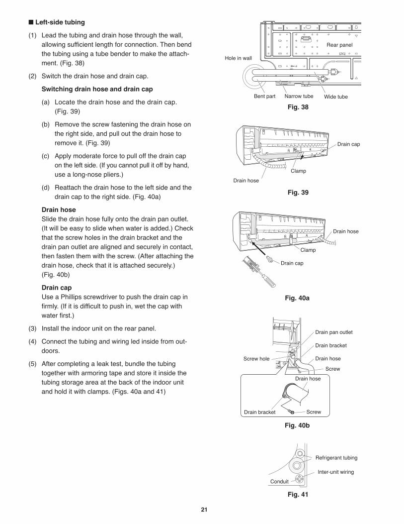
21
Hole in wall
Bent part Narrow tube Wide tube
Rear panel
Fig. 38
Drain cap
Drain hose
Clamp
Fig. 39
Left-side tubing
(1) Lead the tubing and drain hose through the wall,allowing sufficient length for connection. Then bendthe tubing using a tube bender to make the attach-ment. (Fig. 38)
(2) Switch the drain hose and drain cap.
Switching drain hose and drain cap
(a) Locate the drain hose and the drain cap. (Fig. 39)
(b) Remove the screw fastening the drain hose onthe right side, and pull out the drain hose toremove it. (Fig. 39)
(c) Apply moderate force to pull off the drain capon the left side. (If you cannot pull it off by hand,use a long-nose pliers.)
(d) Reattach the drain hose to the left side and thedrain cap to the right side. (Fig. 40a)
Drain hoseSlide the drain hose fully onto the drain pan outlet.(It will be easy to slide when water is added.) Checkthat the screw holes in the drain bracket and thedrain pan outlet are aligned and securely in contact,then fasten them with the screw. (After attaching thedrain hose, check that it is attached securely.) (Fig. 40b)
Drain capUse a Phillips screwdriver to push the drain cap infirmly. (If it is difficult to push in, wet the cap withwater first.)
(3) Install the indoor unit on the rear panel.
(4) Connect the tubing and wiring led inside from out-doors.
(5) After completing a leak test, bundle the tubingtogether with armoring tape and store it inside thetubing storage area at the back of the indoor unitand hold it with clamps. (Figs. 40a and 41)
Fig. 40a
Fig. 40b
Fig. 41
Refrigerant tubing
Inter-unit wiring
Conduit
Drain bracket
Drain pan outlet
Drain hose
Drain bracket
Drain hose
Screw
Screw
Screw hole
Drain hose
Drain cap
Clamp
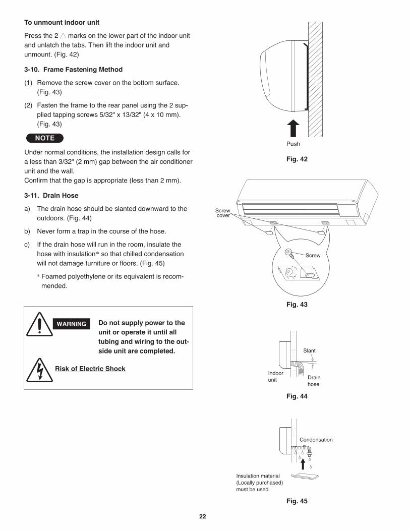
22
To unmount indoor unit
Press the 2 marks on the lower part of the indoor unitand unlatch the tabs. Then lift the indoor unit andunmount. (Fig. 42)
3-10. Frame Fastening Method
(1) Remove the screw cover on the bottom surface.(Fig. 43)
(2) Fasten the frame to the rear panel using the 2 sup-plied tapping screws 5/32" x 13/32" (4 x 10 mm).(Fig. 43)
Under normal conditions, the installation design calls fora less than 3/32" (2 mm) gap between the air conditionerunit and the wall.Confirm that the gap is appropriate (less than 2 mm).
3-11. Drain Hose
a) The drain hose should be slanted downward to theoutdoors. (Fig. 44)
b) Never form a trap in the course of the hose.
c) If the drain hose will run in the room, insulate thehose with insulation* so that chilled condensationwill not damage furniture or floors. (Fig. 45)
* Foamed polyethylene or its equivalent is recom-mended.
NOTE
WARNING
Risk of Electric Shock
Do not supply power to theunit or operate it until alltubing and wiring to the out-side unit are completed.
Condensation
Insulation material(Locally purchased)must be used.
Fig. 45
Screw cover
Screw
Fig. 43
Push
Fig. 42
Slant
Drainhose
Indoorunit
Fig. 44
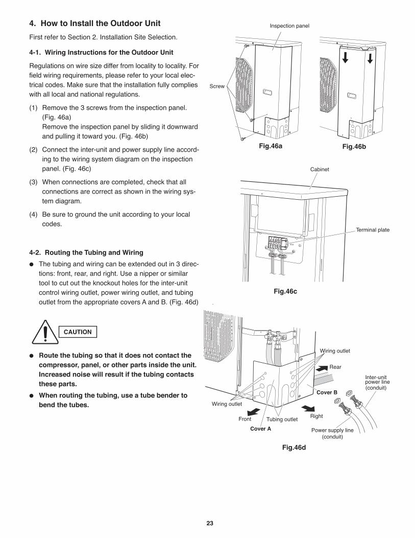
23
4. How to Install the Outdoor Unit
First refer to Section 2. Installation Site Selection.
4-1. Wiring Instructions for the Outdoor Unit
Regulations on wire size differ from locality to locality. Forfield wiring requirements, please refer to your local elec-trical codes. Make sure that the installation fully complieswith all local and national regulations.
(1) Remove the 3 screws from the inspection panel.(Fig. 46a)Remove the inspection panel by sliding it downwardand pulling it toward you. (Fig. 46b)
(2) Connect the inter-unit and power supply line accord-ing to the wiring system diagram on the inspectionpanel. (Fig. 46c)
(3) When connections are completed, check that allconnections are correct as shown in the wiring sys-tem diagram.
(4) Be sure to ground the unit according to your localcodes.
4-2. Routing the Tubing and Wiring
The tubing and wiring can be extended out in 3 direc-tions: front, rear, and right. Use a nipper or similartool to cut out the knockout holes for the inter-unitcontrol wiring outlet, power wiring outlet, and tubingoutlet from the appropriate covers A and B. (Fig. 46d)
Route the tubing so that it does not contact thecompressor, panel, or other parts inside the unit.Increased noise will result if the tubing contactsthese parts.
When routing the tubing, use a tube bender tobend the tubes.
CAUTION
Fig.46a Fig.46b
Fig.46c
Cover B
Cover A
Fig.46d
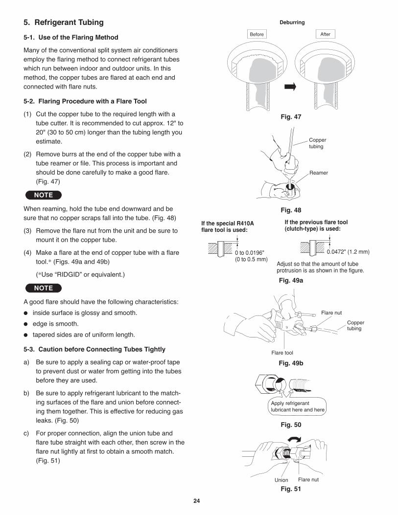
24
5. Refrigerant Tubing
5-1. Use of the Flaring Method
Many of the conventional split system air conditionersemploy the flaring method to connect refrigerant tubeswhich run between indoor and outdoor units. In thismethod, the copper tubes are flared at each end andconnected with flare nuts.
5-2. Flaring Procedure with a Flare Tool
(1) Cut the copper tube to the required length with atube cutter. It is recommended to cut approx. 12" to20" (30 to 50 cm) longer than the tubing length youestimate.
(2) Remove burrs at the end of the copper tube with atube reamer or file. This process is important andshould be done carefully to make a good flare. (Fig. 47)
When reaming, hold the tube end downward and besure that no copper scraps fall into the tube. (Fig. 48)
(3) Remove the flare nut from the unit and be sure tomount it on the copper tube.
(4) Make a flare at the end of copper tube with a flaretool.* (Figs. 49a and 49b)
(*Use “RIDGID” or equivalent.)
A good flare should have the following characteristics:
inside surface is glossy and smooth.
edge is smooth.
tapered sides are of uniform length.
5-3. Caution before Connecting Tubes Tightly
a) Be sure to apply a sealing cap or water-proof tapeto prevent dust or water from getting into the tubesbefore they are used.
b) Be sure to apply refrigerant lubricant to the match-ing surfaces of the flare and union before connect-ing them together. This is effective for reducing gasleaks. (Fig. 50)
c) For proper connection, align the union tube andflare tube straight with each other, then screw in theflare nut lightly at first to obtain a smooth match.(Fig. 51)
NOTE
NOTE
Deburring
Before After
Fig. 47
Reamer
Coppertubing
Fig. 48
Flare tool
Flare nut
Coppertubing
Fig. 49b
Fig. 49a
Apply refrigerant lubricant here and here
Fig. 50
Flare nutUnion
Fig. 51
0 to 0.0196"(0 to 0.5 mm)
If the special R410A flare tool is used:
0.0472" (1.2 mm)
If the previous flare tool (clutch-type) is used:
Adjust so that the amount of tube protrusion is as shown in the figure.
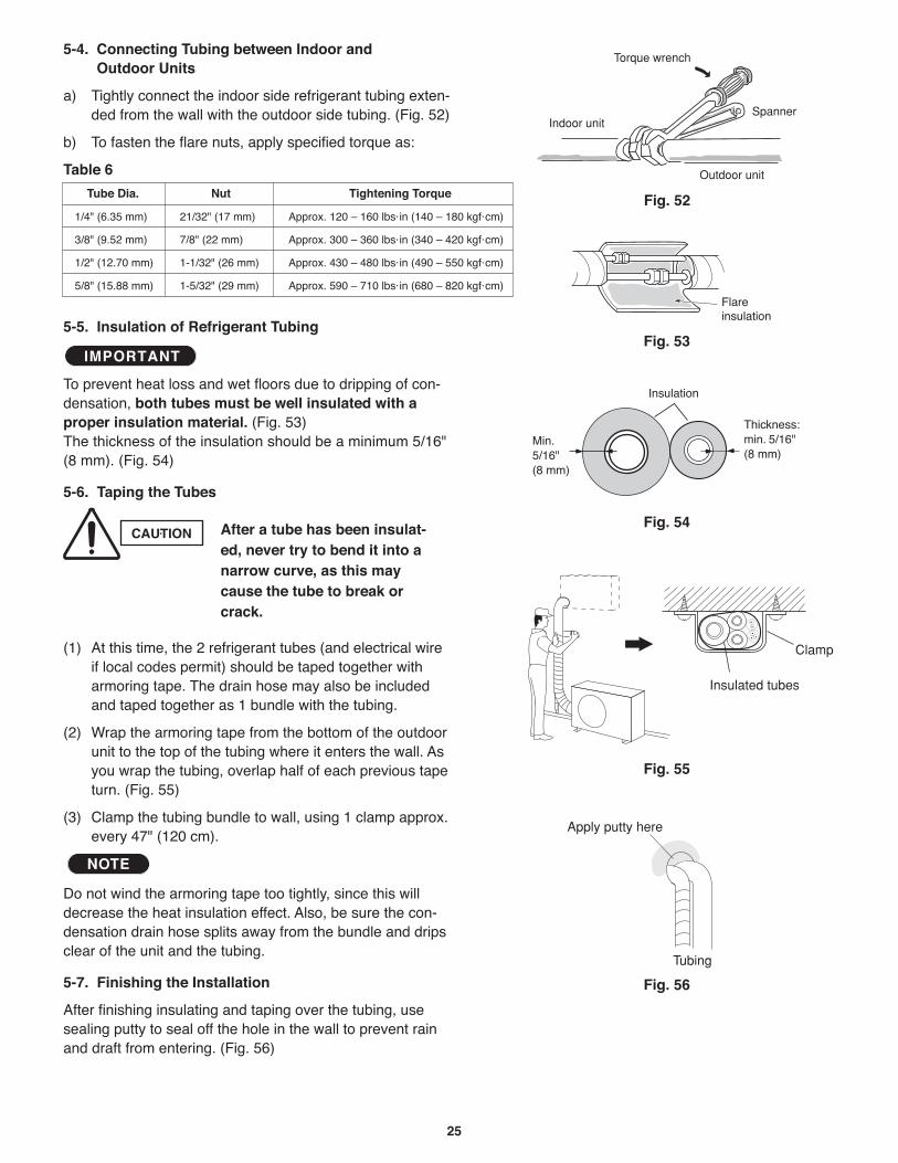
25
5-4. Connecting Tubing between Indoor and Outdoor Units
a) Tightly connect the indoor side refrigerant tubing exten-ded from the wall with the outdoor side tubing. (Fig. 52)
b) To fasten the flare nuts, apply specified torque as:
Table 6
5-5. Insulation of Refrigerant Tubing
To prevent heat loss and wet floors due to dripping of con-densation, both tubes must be well insulated with aproper insulation material. (Fig. 53) The thickness of the insulation should be a minimum 5/16"(8 mm). (Fig. 54)
5-6. Taping the Tubes
(1) At this time, the 2 refrigerant tubes (and electrical wireif local codes permit) should be taped together witharmoring tape. The drain hose may also be includedand taped together as 1 bundle with the tubing.
(2) Wrap the armoring tape from the bottom of the outdoorunit to the top of the tubing where it enters the wall. Asyou wrap the tubing, overlap half of each previous tapeturn. (Fig. 55)
(3) Clamp the tubing bundle to wall, using 1 clamp approx.every 47" (120 cm).
Do not wind the armoring tape too tightly, since this willdecrease the heat insulation effect. Also, be sure the con-densation drain hose splits away from the bundle and dripsclear of the unit and the tubing.
5-7. Finishing the Installation
After finishing insulating and taping over the tubing, usesealing putty to seal off the hole in the wall to prevent rainand draft from entering. (Fig. 56)
NOTE
IMPORTANT
Indoor unit
Outdoor unit
Spanner
Torque wrench
Fig. 52
Insulation
Min. 5/16"(8 mm)
Thickness:min. 5/16"(8 mm)
Fig. 54
Fig. 55
Clamp
Insulated tubes
Apply putty here
Tubing
Fig. 56
CAUTION After a tube has been insulat-ed, never try to bend it into anarrow curve, as this maycause the tube to break orcrack.
Fig. 53
Tube Dia. Nut Tightening Torque
1/4" (6.35 mm) 21/32" (17 mm) Approx. 120 – 160 lbs·in (140 – 180 kgf·cm)
3/8" (9.52 mm) 7/8" (22 mm) Approx. 300 – 360 lbs·in (340 – 420 kgf·cm)
1/2" (12.70 mm) 1-1/32" (26 mm) Approx. 430 – 480 lbs·in (490 – 550 kgf·cm)
5/8" (15.88 mm) 1-5/32" (29 mm) Approx. 590 – 710 lbs·in (680 – 820 kgf·cm)
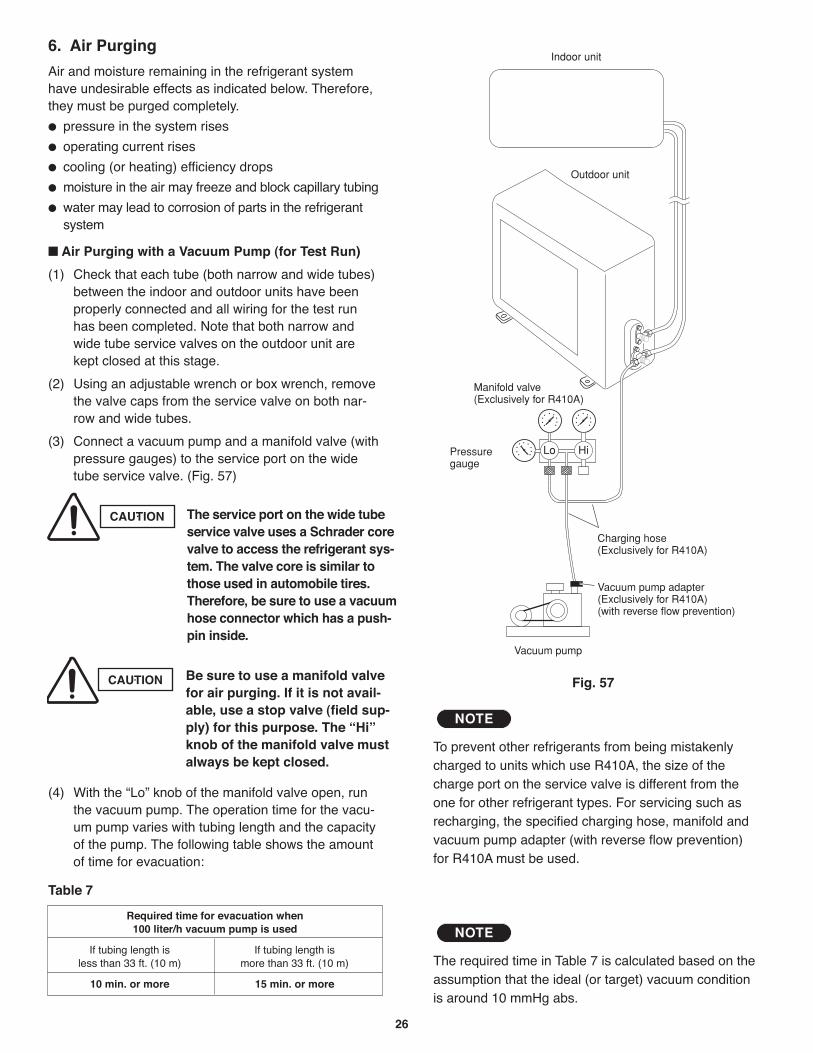
26
6. Air Purging
Air and moisture remaining in the refrigerant systemhave undesirable effects as indicated below. Therefore,they must be purged completely.
pressure in the system rises
operating current rises
cooling (or heating) efficiency drops
moisture in the air may freeze and block capillary tubing
water may lead to corrosion of parts in the refrigerantsystem
Air Purging with a Vacuum Pump (for Test Run)
(1) Check that each tube (both narrow and wide tubes)between the indoor and outdoor units have beenproperly connected and all wiring for the test runhas been completed. Note that both narrow andwide tube service valves on the outdoor unit arekept closed at this stage.
(2) Using an adjustable wrench or box wrench, removethe valve caps from the service valve on both nar-row and wide tubes.
(3) Connect a vacuum pump and a manifold valve (withpressure gauges) to the service port on the widetube service valve. (Fig. 57)
(4) With the “Lo” knob of the manifold valve open, runthe vacuum pump. The operation time for the vacu-um pump varies with tubing length and the capacityof the pump. The following table shows the amountof time for evacuation:
Table 7
HiLo
Indoor unit
Outdoor unit
Manifold valve(Exclusively for R410A)
Pressuregauge
Vacuum pump
Charging hose(Exclusively for R410A)
Vacuum pump adapter(Exclusively for R410A)(with reverse flow prevention)
Fig. 57CAUTION Be sure to use a manifold valvefor air purging. If it is not avail-able, use a stop valve (field sup-ply) for this purpose. The “Hi”knob of the manifold valve mustalways be kept closed.
The required time in Table 7 is calculated based on theassumption that the ideal (or target) vacuum conditionis around 10 mmHg abs.
NOTERequired time for evacuation when
100 liter/h vacuum pump is used
If tubing length is If tubing length isless than 33 ft. (10 m) more than 33 ft. (10 m)
10 min. or more 15 min. or more
CAUTION The service port on the wide tubeservice valve uses a Schrader corevalve to access the refrigerant sys-tem. The valve core is similar tothose used in automobile tires.Therefore, be sure to use a vacuumhose connector which has a push-pin inside.
To prevent other refrigerants from being mistakenlycharged to units which use R410A, the size of thecharge port on the service valve is different from theone for other refrigerant types. For servicing such asrecharging, the specified charging hose, manifold andvacuum pump adapter (with reverse flow prevention)for R410A must be used.
NOTE
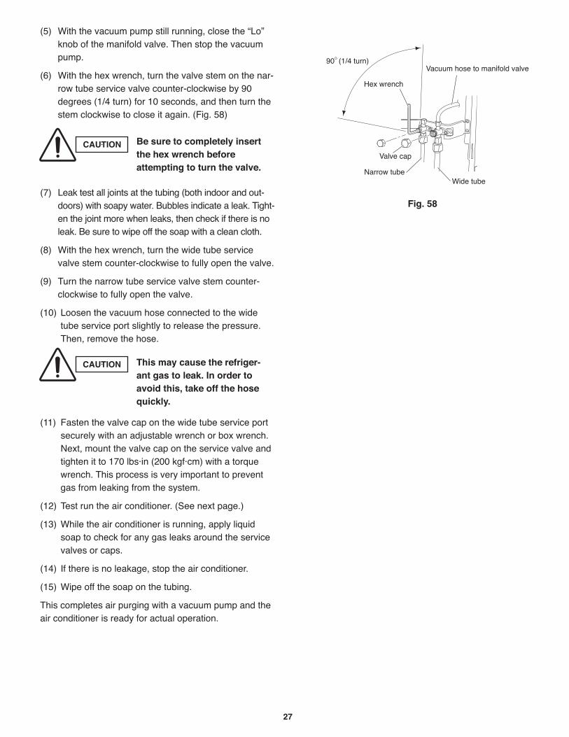
27
(5) With the vacuum pump still running, close the “Lo”knob of the manifold valve. Then stop the vacuumpump.
(6) With the hex wrench, turn the valve stem on the nar-row tube service valve counter-clockwise by 90degrees (1/4 turn) for 10 seconds, and then turn thestem clockwise to close it again. (Fig. 58)
(7) Leak test all joints at the tubing (both indoor and out-doors) with soapy water. Bubbles indicate a leak. Tight-en the joint more when leaks, then check if there is noleak. Be sure to wipe off the soap with a clean cloth.
(8) With the hex wrench, turn the wide tube servicevalve stem counter-clockwise to fully open the valve.
(9) Turn the narrow tube service valve stem counter-clockwise to fully open the valve.
(10) Loosen the vacuum hose connected to the widetube service port slightly to release the pressure.Then, remove the hose.
(11) Fasten the valve cap on the wide tube service portsecurely with an adjustable wrench or box wrench.Next, mount the valve cap on the service valve andtighten it to 170 lbs·in (200 kgf·cm) with a torquewrench. This process is very important to preventgas from leaking from the system.
(12) Test run the air conditioner. (See next page.)
(13) While the air conditioner is running, apply liquidsoap to check for any gas leaks around the servicevalves or caps.
(14) If there is no leakage, stop the air conditioner.
(15) Wipe off the soap on the tubing.
This completes air purging with a vacuum pump and theair conditioner is ready for actual operation.
CAUTION Be sure to completely insertthe hex wrench beforeattempting to turn the valve.
Fig. 58
CAUTION This may cause the refriger-ant gas to leak. In order toavoid this, take off the hosequickly.
Valve cap
Narrow tube
Hex wrench
Wide tube
Vacuum hose to manifold valve90 (1/4 turn)
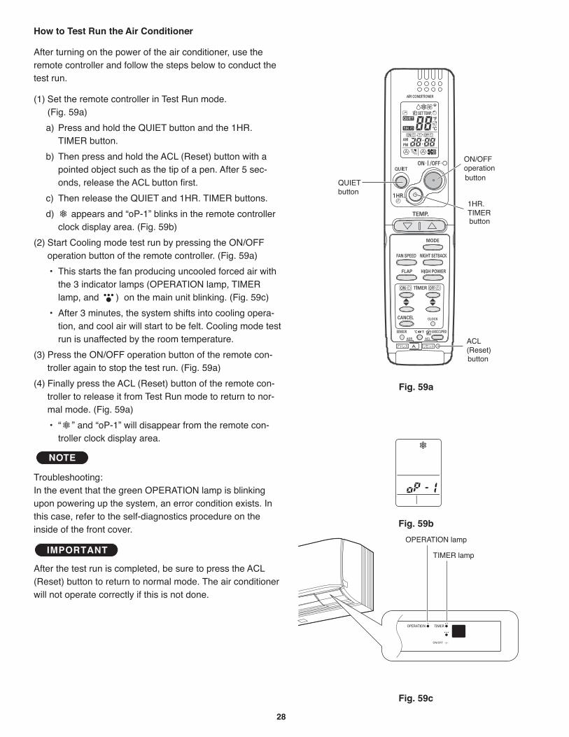
28
How to Test Run the Air Conditioner
After turning on the power of the air conditioner, use theremote controller and follow the steps below to conduct thetest run.
(1) Set the remote controller in Test Run mode. (Fig. 59a)
a) Press and hold the QUIET button and the 1HR.TIMER button.
b) Then press and hold the ACL (Reset) button with apointed object such as the tip of a pen. After 5 sec-onds, release the ACL button first.
c) Then release the QUIET and 1HR. TIMER buttons.
d) appears and “oP-1” blinks in the remote controllerclock display area. (Fig. 59b)
(2) Start Cooling mode test run by pressing the ON/OFFoperation button of the remote controller. (Fig. 59a)
the 3 indicator lamps (OPERATION lamp, TIMERlamp, and ) on the main unit blinking. (Fig. 59c)
tion, and cool air will start to be felt. Cooling mode testrun is unaffected by the room temperature.
(3) Press the ON/OFF operation button of the remote con-troller again to stop the test run. (Fig. 59a)
(4) Finally press the ACL (Reset) button of the remote con-troller to release it from Test Run mode to return to nor-mal mode. (Fig. 59a)
troller clock display area.
Troubleshooting:In the event that the green OPERATION lamp is blinkingupon powering up the system, an error condition exists. Inthis case, refer to the self-diagnostics procedure on theinside of the front cover.
After the test run is completed, be sure to press the ACL(Reset) button to return to normal mode. The air conditionerwill not operate correctly if this is not done.
IMPORTANT
NOTE
Fig. 59a
Fig. 59b
Fig. 59c
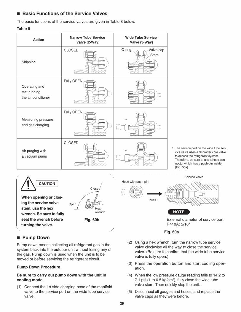
29
Pump DownPump down means collecting all refrigerant gas in thesystem back into the outdoor unit without losing any ofthe gas. Pump down is used when the unit is to bemoved or before servicing the refrigerant circuit.
Pump Down Procedure
Be sure to carry out pump down with the unit incooling mode.
(1) Connect the Lo side charging hose of the manifoldvalve to the service port on the wide tube servicevalve.
(2) Using a hex wrench, turn the narrow tube servicevalve clockwise all the way to close the servicevalve. (Be sure to confirm that the wide tube servicevalve is fully open.)
(3) Press the operation button and start cooling oper-ation.
(4) When the low pressure gauge reading falls to 14.2 to7.1 psi (1 to 0.5 kg/cm2), fully close the wide tubevalve stem. Then quickly stop the unit.
(5) Disconnect all gauges and hoses, and replace thevalve caps as they were before.
Basic Functions of the Service Valves
The basic functions of the service valves are given in Table 8 below.
ActionNarrow Tube Service
Valve (2-Way)Wide Tube Service
Valve (3-Way)
CLOSED
Fully OPEN
Fully OPEN
Shipping
Operating and
test running
the air conditioner
Measuring pressure
and gas charging
Air purging with
a vacuum pump
CLOSED
Valve capStem
O-ring
*
*
Table 8
* The service port on the wide tube ser-vice valve uses a Schrader core valveto access the refrigerant system.Therefore, be sure to use a hose con-nector which has a push-pin inside.(Fig. 60a)
PUSH
Hose with push-pin
Service valve
Fig. 60a
Close
Hexwrench
Open
Fig. 60b
CAUTION
When opening or clos-ing the service valvestem, use the hexwrench. Be sure to fullyseat the wrench beforeturning the valve.
External diameter of service portR410A: 5/16"
NOTE
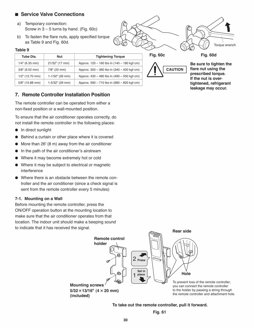
30
Fig. 60c Fig. 60d
CAUTIONBe sure to tighten the flare nut using the prescribed torque. If the nut is over-tightened, refrigerant leakage may occur.
Press
Set in place
Remote controlholder
Mounting s crew s
Rear side
Hole
5/32 13/16" (4 20 mm)(included)
7. Remote Controller Installation Position
The remote controller can be operated from either anon-fixed position or a wall-mounted position.
To ensure that the air conditioner operates correctly, donot install the remote controller in the following places:
In direct sunlight
Behind a curtain or other place where it is covered
More than 26' (8 m) away from the air conditioner
In the path of the air conditioner’s airstream
Where it may become extremely hot or cold
Where it may be subject to electrical or magneticinterference
Where there is an obstacle between the remote con-troller and the air conditioner (since a check signal issent from the remote controller every 5 minutes)
7-1. Mounting on a WallBefore mounting the remote controller, press theON/OFF operation button at the mounting location tomake sure that the air conditioner operates from thatlocation. The indoor unit should make a beeping soundto indicate that it has received the signal.
Table 9
Fig. 61
To take out the remote controller, pull it forward.
Service Valve Connections
Tube Dia. Nut Tightening Torque
1/4" (6.35 mm) 21/32" (17 mm) Approx. 120 – 160 lbs·in (140 – 180 kgf·cm)
3/8" (9.52 mm) 7/8" (22 mm) Approx. 300 – 360 lbs·in (340 – 420 kgf·cm)
1/2" (12.70 mm) 1-1/32" (26 mm) Approx. 430 – 480 lbs·in (490 – 550 kgf·cm)
5/8" (15.88 mm) 1-5/32" (29 mm) Approx. 590 – 710 lbs·in (680 – 820 kgf·cm)
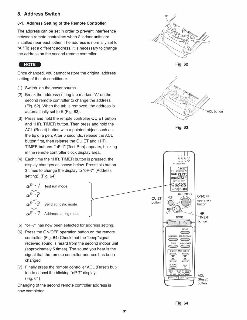
31
8. Address Switch
8-1. Address Setting of the Remote Controller
The address can be set in order to prevent interferencebetween remote controllers when 2 indoor units areinstalled near each other. The address is normally set to“A.” To set a different address, it is necessary to changethe address on the second remote controller.
Once changed, you cannot restore the original addresssetting of the air conditioner.
(1) Switch on the power source.
(2) Break the address-setting tab marked “A” on thesecond remote controller to change the address(Fig. 62). When the tab is removed, the address isautomatically set to B (Fig. 63).
(3) Press and hold the remote controller QUIET buttonand 1HR. TIMER button. Then press and hold theACL (Reset) button with a pointed object such asthe tip of a pen. After 5 seconds, release the ACLbutton first, then release the QUIET and 1HR.TIMER buttons. “oP-1” (Test Run) appears, blinkingin the remote controller clock display area.
(4) Each time the 1HR. TIMER button is pressed, thedisplay changes as shown below. Press this button3 times to change the display to “oP-7” (Address setting). (Fig. 64)
(5) “oP-7” has now been selected for address setting.
(6) Press the ON/OFF operation button on the remotecontroller. (Fig. 64) Check that the “beep”signal-received sound is heard from the second indoor unit(approximately 5 times). The sound you hear is thesignal that the remote controller address has beenchanged.
(7) Finally press the remote controller ACL (Reset) but-ton to cancel the blinking “oP-7” display. (Fig. 64)
Changing of the second remote controller address isnow completed.
NOTE Fig. 62
Fig. 63
Fig. 64
Tab

DC1111-0