Embed Size (px)
Citation preview
TD 003 – V4 KARTING AUSTRALIA
Technical Document No. TD-‐003 Technical Regulations for KA2 Document Number TD-‐003 Reviewed By CEO Drafted By Version Implementation Date
National Technical Commissioner V4 -‐ 09 01 17 Immediate
Approved by CEO on 10 January 2017 Scheduled Review Date 31 December 2017
These Technical Regulations (‘Regulations’) are to be read in conjunction with Class Rules Chapter 9 of the 2017 Karting Australia Manual. For the avoidance of doubt, these Regulations are supplementary to the Rules and are to provide additional specific technical information for the KA2 Class. 1.1 Eligible engines
a) In accordance with Class Rules Chapter 9 of the 2016 Karting Australia Manual 1.2 Radiator:
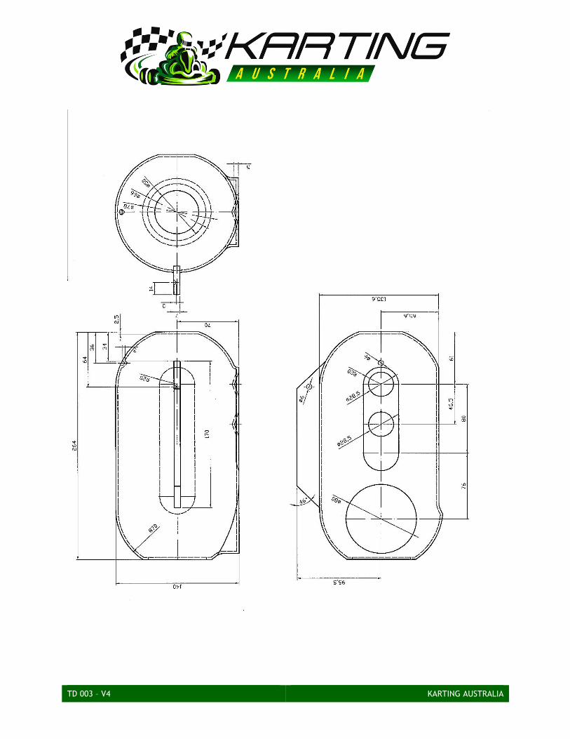
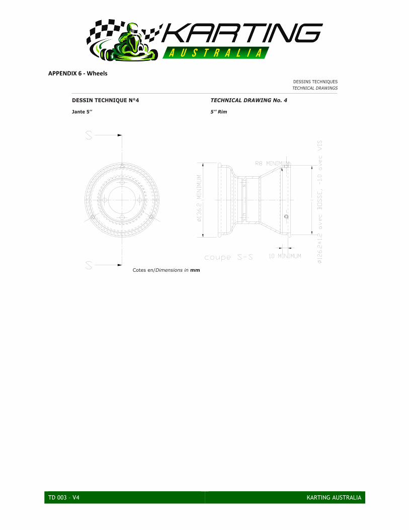
a) The radiator style, type and size is at the discretion of the Competitor. 1.3 Wheels The use of wheels complying with the CIK-‐FIA technical drawing No. 4 (Appendix 6 of these Regulations) is compulsory:
a) Diameter of coupling for tyres: for 5 inch rims: 126.2 mm with a tolerance of +/-‐1.2 for the circumference with the hump and a tolerance of -‐1 for the diameter of rims with screws.
b) Width of the tyre housing: 10 mm minimum. c) External diameter for 5 inch rims: 136.2 mm minimum. d) Radius to facilitate the balance of the tyre in it’s housing: 8 mm. e) Maximum pressure for assembly: 4 Bar. f) Tyre burst resistance test with fluid at an 8 Bar pressure.
TD 003 – V4 KARTING AUSTRALIA
MODIFICATIONS AND TECHNICAL REGULATIONS 2.1 General
a) All aspects of the Vortex DVS engine must comply with KA Homologation Document 116H. No modifications are permitted unless they are described in the Homologation Document.
b) The modifications and additional technical regulations in this Regulation 2 applies only to the Vortex 39/M/18-‐KF3 engine.
2.2 Modifications
a) Any modification is forbidden if it is not explicitly authorised by an article of these Regulations or for safety reasons decided by the CIK-‐FIA or KA.
b) By modification it is meant any operations likely to change the initial aspect, the dimensions, the drawings or the photographs of an original homologated part represented on the Homologation Form.
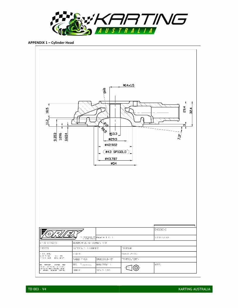
c) The cylinder head may be repaired/modified to a maximum tolerance of -‐0.2mm of the dimension on the homologation document (Appendix 1 of these Regulations). The minimum volume of the Combustion chamber is 14 cc, measured in accordance with KA cc measuring method. No material may be added to the cylinder.
d) Cylinder may be modified except in the following areas: i. Volume of transfer ducts ii. Exhaust duct length iii. Internal profile of the exhaust duct outlet iv. Maximum ports chord width and lower gasket plane of the cylinder according to the
Homologation Form These elements cannot be modified or altered in any way or method and are control surfaces and areas
e) The upper cylinder plane may be repaired but must comply with all dimensions contained within the homologation form.
f) The cylinder ports and passages cannot be modified in any way, and must remain in their original form and conform to the homologation document.
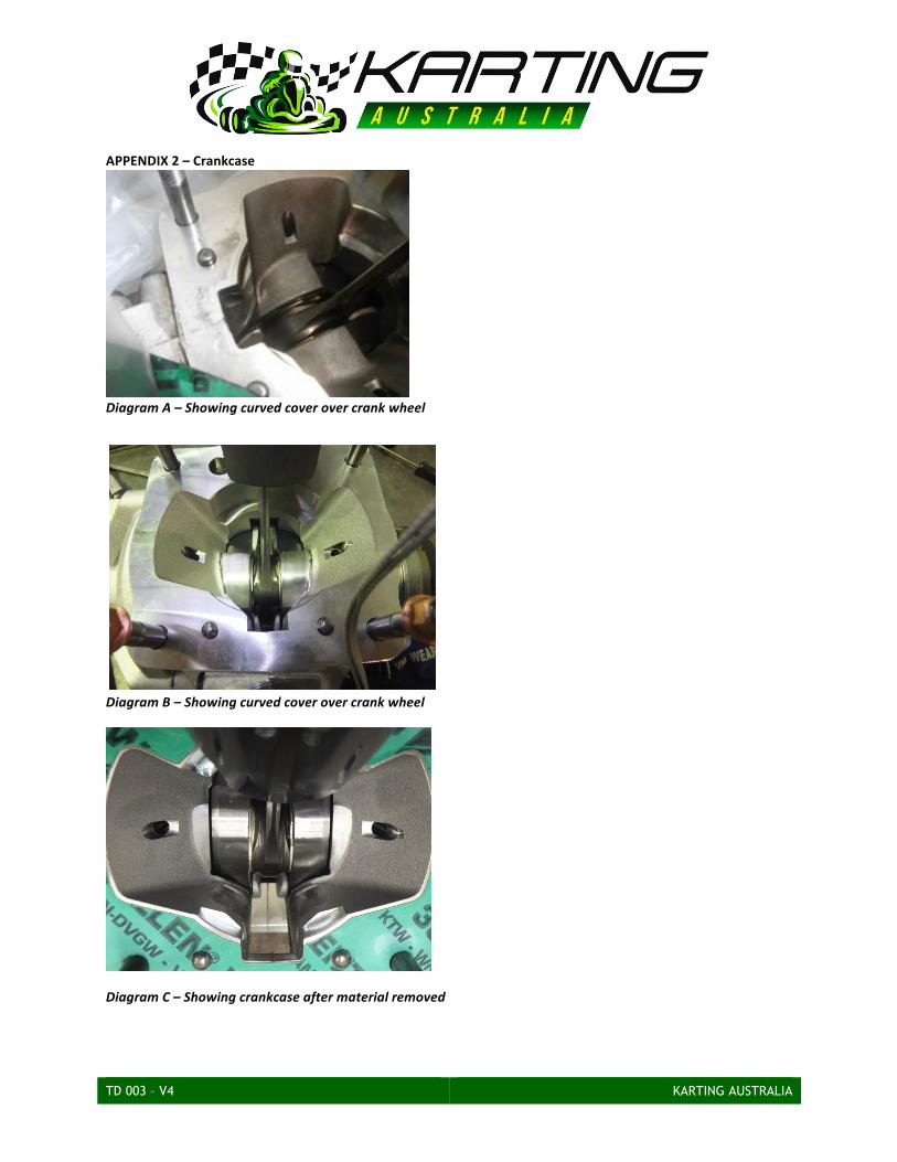
g) It is allowed to replace the spark plug thread by a heli-‐coil h) Power-‐valve is strictly forbidden i) Crankcase/Crankcases may be modified to conform to the new production methods. Crankcases must be
in conformance with either Diagram A, Diagram B or Diagram C in Appendix 2 of these Regulations. j) The crankcase pin is able to be modified k) The drive-‐side balance shaft cover is able to be machined to fit an o-‐ring in aid of sealing the outer edge
2.3 Maximum Theoretical Bore Size
a) The Maximum permitted theoretical bore size is 54.48mm
2.4 Spark Plug a) Spark plug make is free. b) The body of the spark plug (electrodes not included) tightened on the cylinder head, must not extend
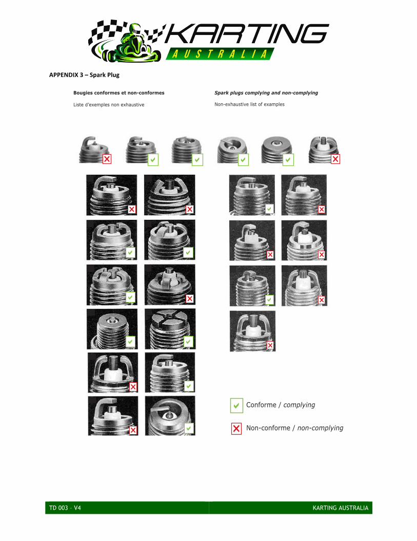
beyond the upper part of the dome of the combustion chamber. c) Spark plug must comply with the images in Appendix 3 of these Regulations.
2.5 Ignition a) CIK-‐FIA homologated ignition system complying to either of the following Homologation Documents must
be used: i. 57/1/15 ii. 57/1/15-‐01/01/ET iii. 57/A/18
b) The Engine RPM is limited to 14,000rpm
TD 003 – V4 KARTING AUSTRALIA
c) The engine ECU program/software cannot be altered or modified d) On decision of the Stewards or Technical Official, they shall be authorised to interchange any part or all of
the Entrants’ ignition systems for the system supplied as original equipment at their discretion for the purpose of checking conformity.
2.6 Exhaust
a) Must be the homologated exhaust for the engine being used. b) Cannot be altered or modified c) The exhaust spacer length is free to a maximum of 20mm OEM spacers. These spacers must be used
without modification d) A maximum of one gasket per face of the spacer is permissible
2.7 Reed block
a) The Original Vortex KF3 Reed Valve Pyramid Intern. Conveyor as supplied with the 39/M/18-‐KF3 engine with no modifications must be used.
2.8 Carburettor
a) The Carburettor must be a 20mm Tryton KF3VAMEC b) Maximum diameter of 20mm c) Must comprise of two set screws d) Must remain strictly original and comply with the CIK-‐FIA Homologation Document 26/C/15 e) The Original Vortex KF3 Carburettor Manifold shall be used as supplied with the 39/M/18-‐KF3 engine with
no modifications permitted. f) Any form of spacer between the Carburettor and the manifold other than a gasket is strictly prohibited.
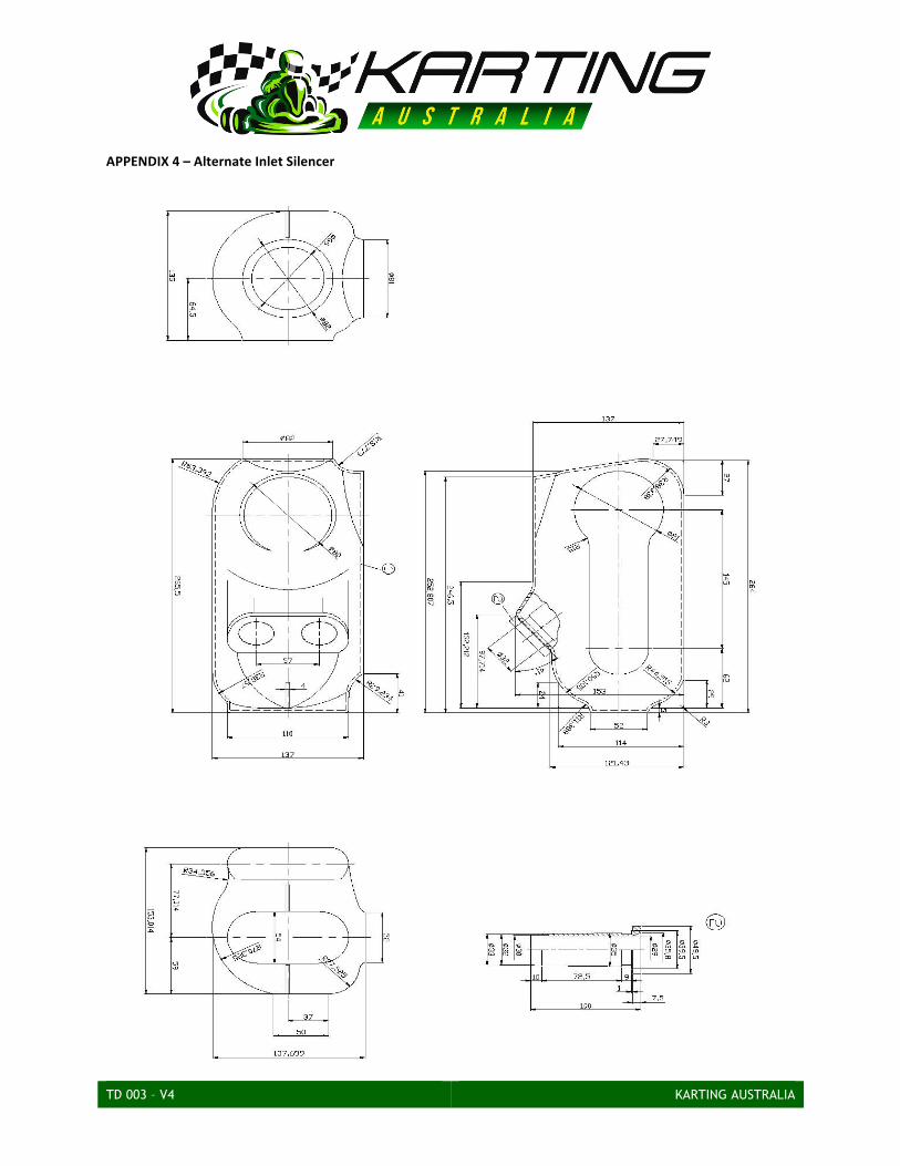
2.9 Air Box (Inlet Silencer) a) The Inlet Silencer can be either a:
i. KG P.No.FA006AG with 23mm ran tubes, or ii. The alternate air boxes with maximum 23mm ram tubes only all other dimensions as per
Appendix 3 of these Regulations. iii.
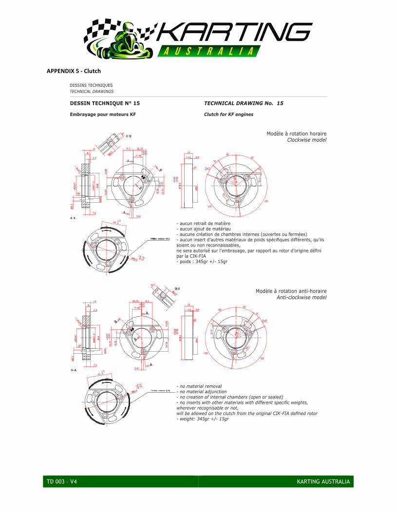
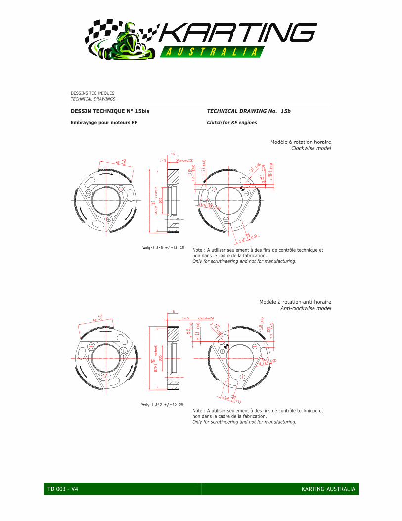
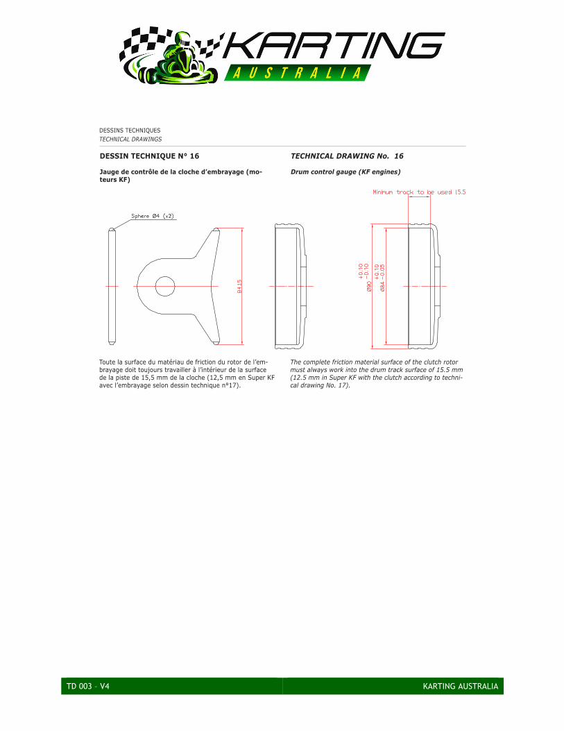
2.10 Clutch a) Must comply with CIK technical drawings No.15, 15b & 16 (Appendix 4 of these Regulations) b) Minimum weight (complete clutch with starter ring and engine sprocket) according to the relevant engine
Homologation Document c) The engine clutch must be triggered at 3,000 rpm maximum and make the kart with the Driver on board
move forward; it must be in direct drive (and 100% engaged) at 5,000 rpm maximum under all circumstances.
TD 003 – V4 KARTING AUSTRALIA
APPENDIX 1 – Cylinder Head
TD 003 – V4 KARTING AUSTRALIA
APPENDIX 2 – Crankcase
Diagram A – Showing curved cover over crank wheel
Diagram B – Showing curved cover over crank wheel
Diagram C – Showing crankcase after material removed
TD 003 – V4 KARTING AUSTRALIA
APPENDIX 3 – Spark Plug
ANNEXES AU REGLEMENT TECHNIQUE
APPENDICES TO THE TECHNICAL REGULATIONS
349
Annexe N°7
Bougies conformes et non-conformes
Liste d’exemples non exhaustive
Appendix No. 7
Spark plugs complying and non-complying
Non-exhaustive list of examples
r r
r a
a
a
a
a a
a
r
r
a
a
r
r
r
r
r
a a a ar r
a
r
Conforme / complying
Non-conforme / non-complying
TD 003 – V4 KARTING AUSTRALIA
APPENDIX 4 – Alternate Inlet Silencer
TD 003 – V4 KARTING AUSTRALIA
TD 003 – V4 KARTING AUSTRALIA
APPENDIX 5 -‐ Clutch
DESSINS TECHNIQUES
TECHNICAL DRAWINGS
362
DESSIN TECHNIQUE N° 15
Embrayage pour moteurs KF
TECHNICAL DRAWING No. 15
Clutch for KF engines
- aucun retrait de matière- aucun ajout de matériau- aucune création de chambres internes (ouvertes ou fermées)- aucun insert d’autres matériaux de poids spécifiques différents, qu’ils soient ou non reconnaissables,ne sera autorisé sur l’embrayage, par rapport au rotor d’origine défini par la CIK-FIA- poids : 345gr +/- 15gr
- no material removal- no material adjunction- no creation of internal chambers (open or sealed)- no inserts with other materials with different specific weights, wherever recognisable or not,will be allowed on the clutch from the original CIK-FIA defined rotor- weight: 345gr +/- 15gr
Modèle à rotation horaireClockwise model
Modèle à rotation anti-horaireAnti-clockwise model
TD 003 – V4 KARTING AUSTRALIA
DESSINS TECHNIQUESTECHNICAL DRAWINGS
12
DESSIN TECHNIQUE N° 15bis
Embrayage pour moteurs KF
TECHNICAL DRAWING No. 15b
Clutch for KF engines
Note : A utiliser seulement à des fins de contrôle technique et non dans le cadre de la fabrication.Only for scrutineering and not for manufacturing.
Note : A utiliser seulement à des fins de contrôle technique et non dans le cadre de la fabrication.Only for scrutineering and not for manufacturing.
Modèle à rotation horaireClockwise model
Modèle à rotation anti-horaireAnti-clockwise model
TD 003 – V4 KARTING AUSTRALIA
DESSINS TECHNIQUES
TECHNICAL DRAWINGS
364
DESSIN TECHNIQUE N° 16
Jauge de contrôle de la cloche d’embrayage (mo-
teurs KF)
TECHNICAL DRAWING No. 16
Drum control gauge (KF engines)
Toute la surface du matériau de friction du rotor de l’em-brayage doit toujours travailler à l’intérieur de la surface de la piste de 15,5 mm de la cloche (12,5 mm en Super KF avec l’embrayage selon dessin technique n°17).
The complete friction material surface of the clutch rotor must always work into the drum track surface of 15.5 mm (12.5 mm in Super KF with the clutch according to techni-cal drawing No. 17).
DESSIN TECHNIQUE N° 18
Cale de mesure des angles d’ouverture
TECHNICAL DRAWING No. 18
Opening angles wedge
Acier / Steel: SANDVIK 7C27Mo2
TD 003 – V4 KARTING AUSTRALIA
APPENDIX 6 -‐ Wheels
DESSINS TECHNIQUES
TECHNICAL DRAWINGS
355
DESSIN TECHNIQUE N°4
Jante 5’’
TECHNICAL DRAWING No. 4
5’’ Rim
Cotes en/Dimensions in mm
TD 003 – V4 KARTING AUSTRALIA
Version Description Approved By Date 4 Inclusion of the Vortex DVS-‐J CEO 23 Dec 2015 6 Updated dates for 2017 CEO 10 Jan 2017