Embed Size (px)
Citation preview

Technician Licensing Class
Feed Me withSome Good Coax!
Section 19
Valid July 1, 2014
Through
June 30, 2018
Feed Me with Some Good Coax!
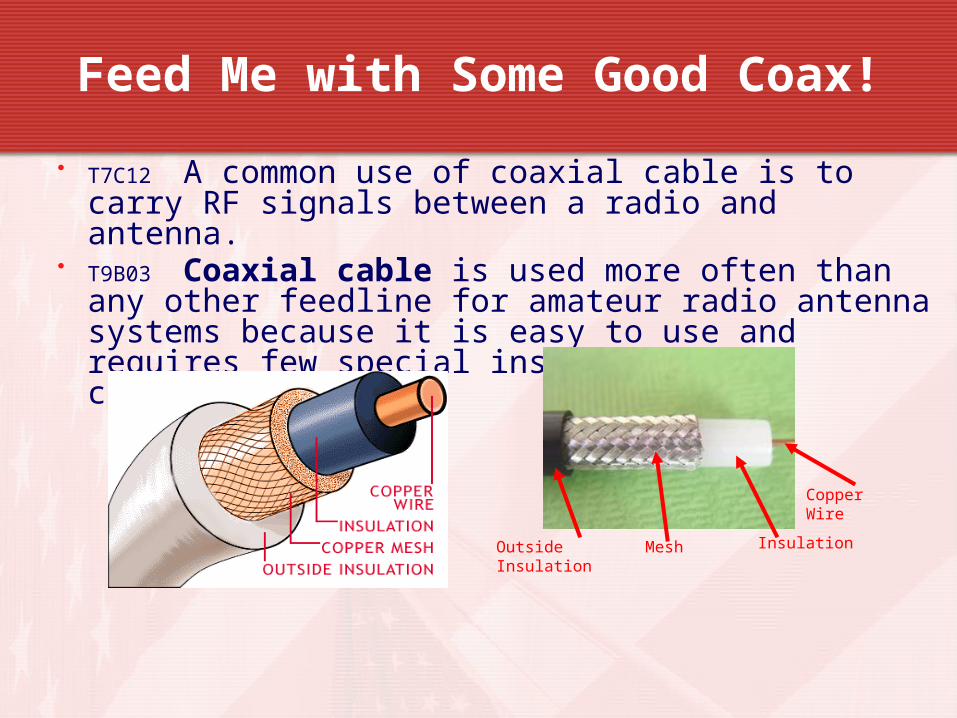
• T7C12 A common use of coaxial cable is to carry RF signals between a radio and antenna.
• T9B03 Coaxial cable is used more often than any other feedline for amateur radio antenna systems because it is easy to use and requires few special installation considerations.
• T9B02 50 ohms is the impedance of the most commonly used coaxial cable in typical amateur radio installations.
Copper Wire
Outside Insulation
Mesh
Insulation
Feed Me with Some Good Coax!
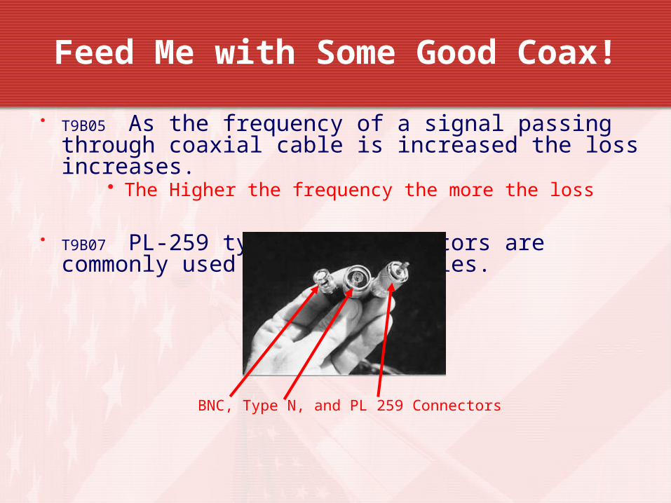
• T9B05 As the frequency of a signal passing through coaxial cable is increased the loss increases.
• The Higher the frequency the more the loss
• T9B07 PL-259 type coax connectors are commonly used at HF frequencies.
• T9B06 A Type N connector is most suitable for frequencies above 400 MHz.
BNC, Type N, and PL 259 Connectors
Feed Me with Some Good Coax!
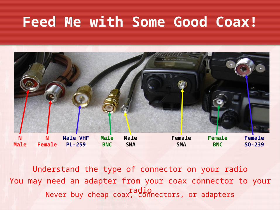
Male SMA
Male BNC
Male VHF PL-259
N Female
N Male
Female SMA
Female BNC
Female SO-239
Understand the type of connector on your radio
You may need an adapter from your coax connector to your radio
Never buy cheap coax, connectors, or adapters
Feed Me with Some Good Coax!
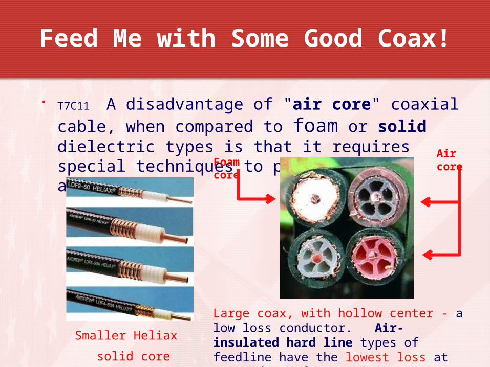
• T7C11 A disadvantage of "air core" coaxial cable, when compared to foam or solid dielectric types is that it requires special techniques to prevent water absorption.
Large coax, with hollow center - a low loss conductor. Air-insulated hard line types of feedline have the lowest loss at VHF and UHF frequencies T9B11
Smaller Heliax
solid core
Foam core
Air core
Feed Me with Some Good Coax!
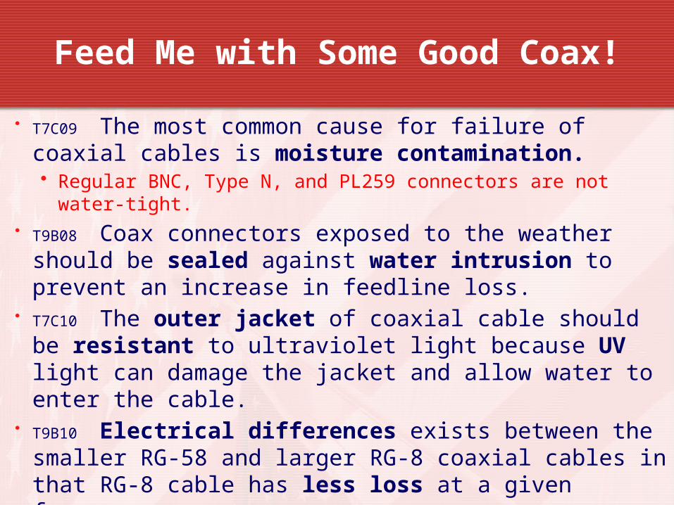
• T7C09 The most common cause for failure of coaxial cables is moisture contamination.• Regular BNC, Type N, and PL259 connectors are not water-tight.
• T9B08 Coax connectors exposed to the weather should be sealed against water intrusion to prevent an increase in feedline loss.
• T7C10 The outer jacket of coaxial cable should be resistant to ultraviolet light because UV light can damage the jacket and allow water to enter the cable.
• T9B10 Electrical differences exists between the smaller RG-58 and larger RG-8 coaxial cables in that RG-8 cable has less loss at a given frequency.
Feed Me with Some Good Coax!
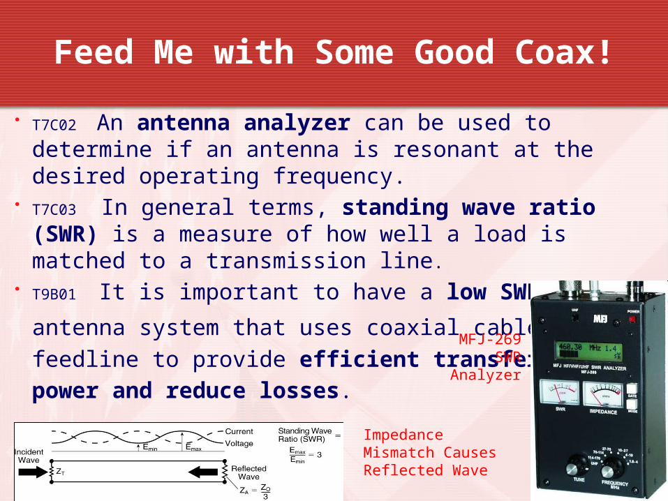
• T7C02 An antenna analyzer can be used to determine if an antenna is resonant at the desired operating frequency.
• T7C03 In general terms, standing wave ratio (SWR) is a measure of how well a load is matched to a transmission line.
• T9B01 It is important to have a low SWR in an
antenna system that uses coaxial cable feedline to provide efficient transfer of
power and reduce losses.
MFJ-269 SWR
Analyzer
Impedance Mismatch Causes Reflected Wave
Feed Me with Some Good Coax!
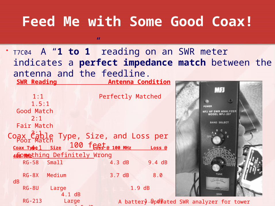
• T7C04 A “1 to 1” reading on an SWR meter indicates a perfect impedance match between the antenna and the feedline.SWR Reading Antenna Condition
1:1 Perfectly Matched 1.5:1 Good Match 2:1 Fair Match 3:1 Poor Match 4:1 Something Definitely Wrong
A battery operated SWR analyzer for tower antenna work
Coax Cable Type, Size, and Loss per 100 feetCoax Type Size Loss @ 100 MHz Loss @ 400
MHz RG-58 Small 4.3 dB 9.4 dB RG-8X Medium 3.7 dB 8.0 dB RG-8U Large 1.9 dB 4.1 dB RG-213 Large 1.9 dB 4.5 dB Hardline Large, Rigid 0.5 dB 1.5 dB
99
Feed Me With Some Good Coax!
21
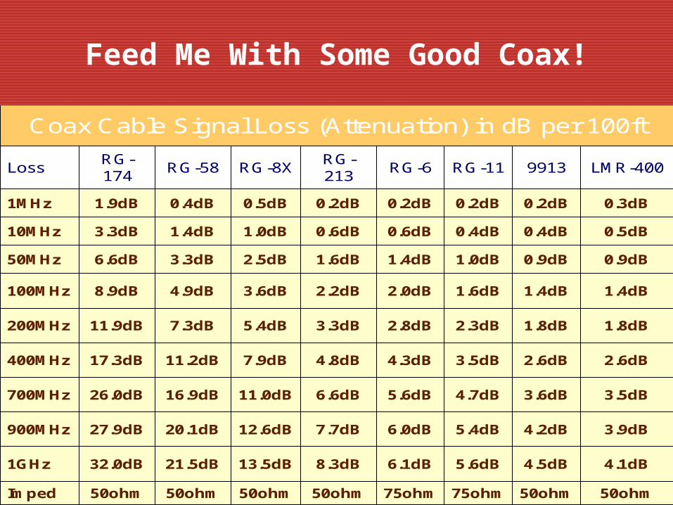
Coax Cable Signal Loss (Attenuation) in dB per 100ft
LossRG-174
RG-58 RG-8XRG-213
RG-6 RG-11 9913 LMR-400
1MHz 1.9dB 0.4dB 0.5dB 0.2dB 0.2dB 0.2dB 0.2dB 0.3dB
10MHz 3.3dB 1.4dB 1.0dB 0.6dB 0.6dB 0.4dB 0.4dB 0.5dB
50MHz 6.6dB 3.3dB 2.5dB 1.6dB 1.4dB 1.0dB 0.9dB 0.9dB
100MHz 8.9dB 4.9dB 3.6dB 2.2dB 2.0dB 1.6dB 1.4dB 1.4dB
200MHz 11.9dB 7.3dB 5.4dB 3.3dB 2.8dB 2.3dB 1.8dB 1.8dB
400MHz 17.3dB 11.2dB 7.9dB 4.8dB 4.3dB 3.5dB 2.6dB 2.6dB
700MHz 26.0dB 16.9dB 11.0dB 6.6dB 5.6dB 4.7dB 3.6dB 3.5dB
900MHz 27.9dB 20.1dB 12.6dB 7.7dB 6.0dB 5.4dB 4.2dB 3.9dB
1GHz 32.0dB 21.5dB 13.5dB 8.3dB 6.1dB 5.6dB 4.5dB 4.1dB
Imped 50ohm 50ohm 50ohm 50ohm 75ohm 75ohm 50ohm 50ohm
Feed Me with Some Good Coax!
• T7C05 2 to 1 is the approximate SWR value above which the protection circuits in most solid-state transmitters begin to reduce transmitter power.
• T7C06 An SWR reading of 4:1 means there is an impedance mismatch.
• T4A05 An in-line SWR meter is connected in series with the feed line, between the transmitter and antenna, to monitor the standing wave ratio of the station antenna system.
Feed Me with Some Good Coax!
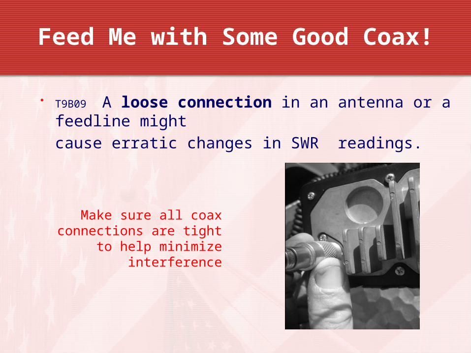
• T9B09 A loose connection in an antenna or a feedline might cause erratic changes in SWRreadings.
Make sure all coax connections are tight to
help minimize interference
Feed Me with Some Good Coax!
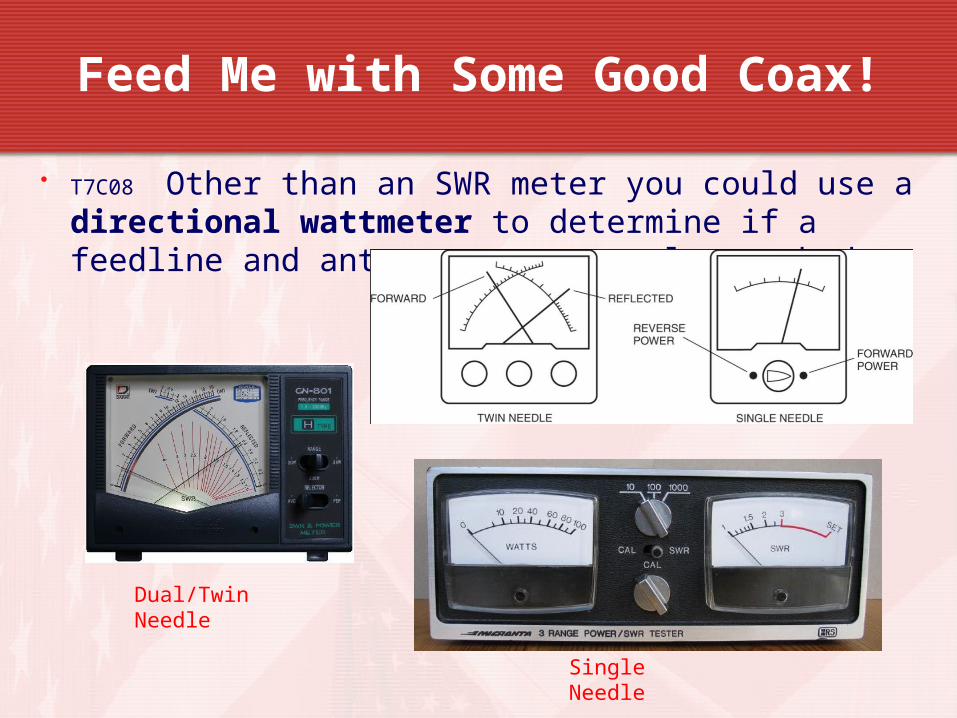
• T7C08 Other than an SWR meter you could use a directional wattmeter to determine if a feedline and antenna are properly matched.
Dual/Twin Needle
Single Needle
Feed Me with Some Good Coax!
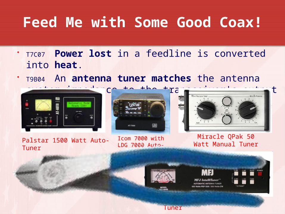
• T7C07 Power lost in a feedline is converted into heat.
• T9B04 An antenna tuner matches the antenna system impedance to the transceiver's output impedance.
Palstar 1500 Watt Auto-Tuner
MFJ-994B 1500 Watt Auto-Tuner
Icom 7000 with LDG 7000 Auto-
Tuner
Miracle QPak 50 Watt Manual Tuner
Feed Me with Some Good Coax!
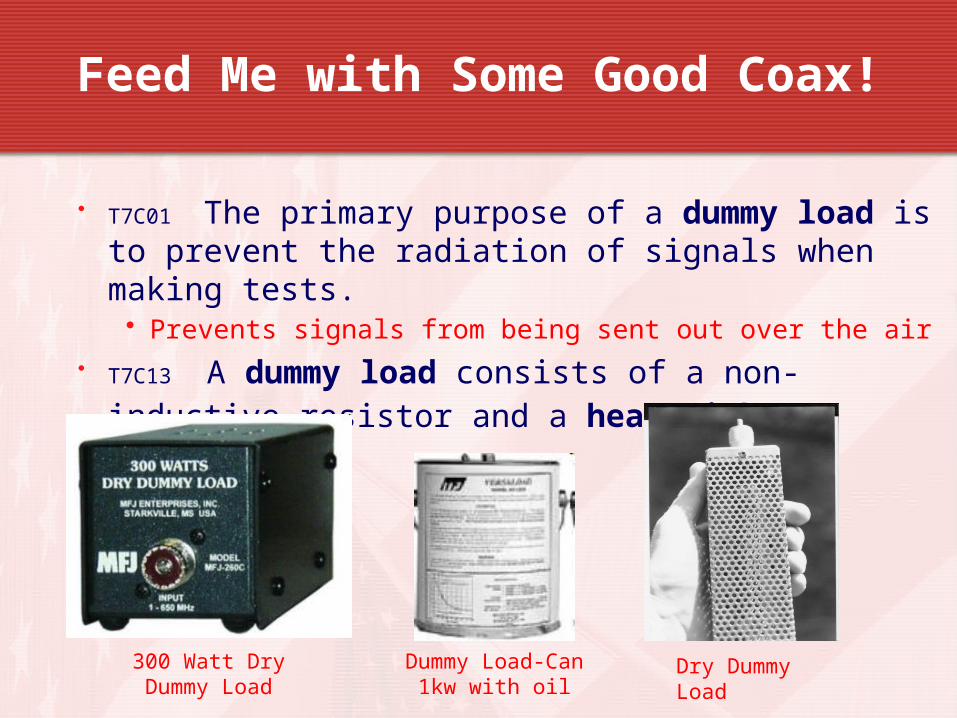
• T7C01 The primary purpose of a dummy load is to prevent the radiation of signals when making tests.• Prevents signals from being sent out over the air
• T7C13 A dummy load consists of a non-inductive resistor and a heat sink .
300 Watt Dry Dummy Load
Dummy Load-Can 1kw with oil
Dry Dummy Load

Take Aways
Take Aways
A common use of coaxial cable is to carry RF signals between a radio and antenna.
The impedance of the most commonly used coaxial cable in typical amateur radio installations is 50 ohms.
Coaxial cable is used more often than any other feedline for amateur radio antenna systems because it is easy to use and requires few special installation considerations.
Generally, the loss increases as the frequency of a signal passing through coaxial cable is increased.
Take Aways
· The PL-259 type coax connectors are commonly used at HF frequencies.
· A Type N connector is most suitable for frequencies above 400 MHz.
· A disadvantage of "air core" coaxial cable when compared to foam or solid dielectric types is that it requires special techniques to prevent water absorption.
· The most common cause for failure of coaxial cables is moisture contamination.
Take Aways
· Coax connectors exposed to the weather should be sealed against water intrusion to prevent an increase in feedline loss.
· The outer jacket of coaxial cable should be resistant to ultraviolet light because ultraviolet light can damage the jacket and allow water to enter the cable.
· The primary electrical difference between the smaller RG-58 and larger RG-8 coaxial cables is that RG-8 cable has less loss at a given frequency.
· Air-insulated hard line types of feedline have the lowest loss at VHF and UHF.
Take Aways
· An antenna analyzer can be used to determine if an antenna is resonant at the desired operating frequency.
· In general terms, standing wave ratio (SWR) is a measure of how well a load is matched to a transmission line.
· It is important to have a low SWR in an antenna system that uses coaxial cable feedline to allow the efficient transfer of power and reduce losses.
· A reading of 1 to 1 on an SWR meter indicates a perfect impedance match between the antenna and the feedline.
Take Aways
· The approximate SWR value above which the protection circuits in most solid-state transmitters begin to reduce transmitter power is
2 to 1.
· An SWR reading of 4:1 means there is an impedance mismatch.
· A loose connection in an antenna or a feedline might cause erratic changes in SWR readings.
· An instrument, other than an SWR meter, that you could use to determine if a feedline and antenna are properly matched is a directional wattmeter.
Take Aways
· An in-line SWR meter is connected in series with the feed line, between the transmitter and antenna, to monitor the standing wave ratio of the station antenna system
· Power lost in a feedline is converted into heat.
· An antenna tuner matches the antenna system impedance to the transceiver's output impedance.
· The primary purpose of a dummy load is to prevent the radiation of signals when making tests
· A dummy load consists of a non-inductive resistor and a heat sink .

Valid July 1, 2014
Through
June 30, 2018
Feed Me with Some Good
Coax!
Element 2 Technician Class Question Pool
23
T7C12 Which of the following is a common use of coaxial cable?
A. Carrying dc power from a vehicle battery to a mobile radio
B. Carrying RF signals between a radio and antenna
C. Securing masts, tubing, and other cylindrical objects on towers
D. Connecting data signals from a TNC to a computer
24
T9B03 Why is coaxial cable used more often than any other feedline for amateur radio antenna systems?
A. It is easy to use and requires few special installation considerations
B. It has less loss than any other type of feedline
C. It can handle more power than any other type of feedline
D. It is less expensive than any other types of feedline
25
T9B02 What is the impedance of the most commonly used coaxial cable in typical amateur radio installations?
A. 8 ohms
B. 50 ohms
C. 600 ohms
D. 12 ohms
26
T9B05 What generally happens as the frequency of a signal passing through coaxial cable is increased?
A. The apparent SWR increases
B. The reflected power increases
C. The characteristic impedance increases
D. The loss increases
27
T9B07 Which of the following is true of PL-259 type coax connectors?
A. They are preferred for microwave operation
B. They are water tight
C. The are commonly used at HF frequencies
D. They are a bayonet type connector
28
T9B06 Which of the following connectors is most suitable for frequencies above 400 MHz?
A. A UHF (PL-259/SO-239) connector
B. A Type N connector
C. An RS-213 connector
D. A DB-25 connector
29
T7C11 What is a disadvantage of air core coaxial cable when compared to foam or solid dielectric types?
A. It has more loss per foot
B. It cannot be used for VHF or UHF antennas
C. It requires special techniques to prevent water absorption
D. It cannot be used at below freezing temperatures
30
T7C09 Which of the following is the most common cause for failure of coaxial cables?
A. Moisture contamination
B. Gamma rays
C. The velocity factor exceeds 1.0
D. Overloading
31
T9B08 Why should coax connectors exposed to the weather be sealed against water intrusion?
A. To prevent an increase in feedline loss
B. To prevent interference to telephones
C. To keep the jacket from becoming loose
D. All of these choices are correct
32
T7C10 Why should the outer jacket of coaxial cable be resistant to ultraviolet light?
A. Ultraviolet resistant jackets prevent harmonic radiation
B. Ultraviolet light can increase losses in the cable’s jacket
C. Ultraviolet and RF signals can mix together, causing interference
D. Ultraviolet light can damage the jacket and allow water to enter the cable
33
T9B10 What electrical difference exists between the smaller RG-58 and larger RG-8 coaxial cables?
A. There is no significant difference between the two types
B. RG-58 cable has less loss at a given frequency
C. RG-8 cable has less loss at a given frequency
D. RG-58 cable can handle higher power levels
34
T9B11 Which of the following types of feedline has the lowest loss at VHF and UHF?
A. 50-ohm flexible coax
B. Multi-conductor unbalanced cable
C. Air-insulated hard line
D. 75-ohm flexible coax
35
T7C02 Which of the following instruments can be used to determine if an antenna is resonant at the desired operating frequency?
A. A VTVM
B. An antenna analyzer
C. A “Q” meter
D. A frequency counter
36
T7C03 What, in general terms, is standing wave ratio (SWR)?
A. A measure of how well a load is matched to a transmission line
B. The ratio of high to low impedance in a feedline
C. The transmitter efficiency ratio
D. An indication of the quality of your station’s ground connection
37
T4A05 Where should an in-line SWR meter be connected to monitor the standing wave ratio of the station antenna system?
A. In series with the feed line, between the transmitter and antenna
B. In series with the station’s ground
C. In parallel with the push-to-talk line and the antenna
D. In series with the power supply cable, as close as possible to the radio
38
T9B01 Why is it important to have a low SWR in an antenna system that uses coaxial cable feed line?
A. To reduce television interference
B. To allow the efficient transfer of power and reduce losses
C. To prolong antenna life
D. All of these choices are correct
39
T7C04 What reading on an SWR meter indicates a perfect impedance match between the antenna and the feedline?
A. 2 to 1
B. 1 to 3
C. 1 to 1
D. 10 to 1
40
T7C05 What is the approximate SWR value above which the protection circuits in most solid-state transmitters begin to reduce transmitter power?
A. 2 to 1
B. 1 to 2
C. 6 to 1
D. 10 to 1
41
T7C06 What does an SWR reading of 4:1 mean?
A. An antenna loss of 4 dB
B. A good impedance match
C. An antenna gain of 4
D. An impedance mismatch
42
T9B09 What might cause erratic changes in SWR readings?
A. The transmitter is being modulated
B. A loose connection in an antenna or a feedline
C. The transmitter is being over-modulated
D. Interference from other stations is distorting your signal
43
T7C08 What instrument other than an SWR meter could you use to determine if a feedline and antenna are properly matched?
A. Voltmeter
B. Ohmmeter
C. Iambic pentameter
D. Directional wattmeter
44
T7C07 What happens to power lost in a feedline?
A. It increases the SWR
B. It comes back into your transmitter and could cause damage
C. It is converted into heat
D. It can cause distortion of your signal
45
T9B04 What does an antenna tuner do?
A. It matches the antenna system impedance to the transceiver's output impedance
B. It helps a receiver automatically tune in weak stations
C. It allows an antenna to be used on both transmit and receive
D. It automatically selects the proper antenna for the frequency band being used
46
T7C01 What is the primary purpose of a dummy load?
A. To prevent the radiation of signals when making tests
B. To prevent over-modulation of your transmitter
C. To improve the radiation from your antenna
D. To improve the signal to noise ratio of your receiver
47
T7C13 What does a dummy load consist of ?
A. A high-gain amplifier and a TR switch
B. A non-inductive resistor and a heat sink
C. A low voltage power supply and a DC relay
D. A 50 ohm reactance used to terminate a transmission line