Embed Size (px)
Citation preview
Modern Automotive Technology
Fundamentals, service, diagnostics
Bearbeitet vonRichard Fischer, Rolf Gscheidle, Tobias Gscheidle, Uwe Heider, Berthold Hohmann, Achim van Huet,
Wolfgang Keil, Rainer Lohuis, Jochen Mann, Bernd Schlögl, Alois Wimmer, Günter Wormer
1. Auflage 2014. Buch. 782 S.ISBN 978 3 8085 2302 5
Format (B x L): 17 x 24 cmGewicht: 1309 g
Weitere Fachgebiete > Technik > Technik Allgemein > Technik: Berufe & Ausbildung
schnell und portofrei erhältlich bei
Die Online-Fachbuchhandlung beck-shop.de ist spezialisiert auf Fachbücher, insbesondere Recht, Steuern und Wirtschaft.Im Sortiment finden Sie alle Medien (Bücher, Zeitschriften, CDs, eBooks, etc.) aller Verlage. Ergänzt wird das Programmdurch Services wie Neuerscheinungsdienst oder Zusammenstellungen von Büchern zu Sonderpreisen. Der Shop führt mehr
als 8 Millionen Produkte.
EUROPA REFERENCE BOOKS
for Automotive Technology
ModernAutomotive Technology Fundamentals, service, diagnostics
2nd English edition
The German edition was written by technical instructors, engineers and technicians
Editorial office (German edition): R. Gscheidle, Studiendirektor, Winnenden – Stuttgart
VERLAG EUROPA-LEHRMITTEL · Nourney, Vollmer GmbH & Co. KG
Düsselberger Straße 23 · 42781 Haan-Gruiten, Germany
Europa-No.: 23018
Modern Automotive Technology - Fundamentals, service, diagnostics, 2nd edition, 2014
Original title: Fachkunde Kraftfahrzeugtechnik, 30th edition, 2013
Authors:
Fischer, Richard Studiendirektor Polling – Munich
Gscheidle, Rolf Studiendirektor Winnenden – Stuttgart
Gscheidle, Tobias Dipl.-Gwl., Studienrat Stuttgart – Sindelfingen
Heider, Uwe Kfz-Elektriker-Meister, Trainer Audi AG Neckarsulm – Oedheim
Hohmann, Berthold Studiendirektor Eversberg – Meschede
van Huet, Achim Dipl.-Ingenieur, Oberstudienrat Oberhausen – Essen
Keil, Wolfgang Oberstudiendirektor Munich
Lohuis, Rainer Dipl.-Ingenieur, Oberstudienrat Hückelhoven – Cologne-Deutz
Mann, Jochen Dipl.-Gwl., Studiendirektor Schorndorf – Stuttgart
Schlögl, Bernd Dipl.-Gwl., Studiendirektor Rastatt – Gaggenau
Wimmer, Alois Oberstudienrat Stuttgart
Wormer, Günter Dipl.-Ingenieur Karlsruhe
Head of working group and editorial office:
Rolf Gscheidle, Studiendirektor, Winnenden – Stuttgart, Germany
Illustrations:
Drawing office of Verlag Europa-Lehrmittel, Ostfildern, Germany
All information given in this book corresponds to the state of the art. All testing, measuring and repair
work on a specific vehicle must be carried out in accordance with the manufacturer's specifications.
The work described is performed at the user's own risk. Warranty claims against the authors or the
publisher are excluded.
2nd edition 2014
Impression 5 4 3 2 1
All impressions of the same edition can be used in parallel, as they do not differ from each other except with regard
to the correction of printing errors.
ISBN 978-3-8085-2302-5
All rights reserved. This book is protected by copyright. Any commercial use beyond the legally specified uses
requires written approval from the publisher.
Cover design and illustration: Braunwerbeagentur, Stefanie Braun, 42477 Radevormwald, Germany, using photo-
graphs and illustrations provided by Dr. Ing. H. C. Porsche AG, Stuttgart, Audi AG, Ingolstadt, Volkswagen AG,
Wolfsburg, KTM, Mattighofen, Austria (photo: H. Mitterbauer) and Mercedes Benz AG, Stuttgart.
© 2014 by Verlag Europa-Lehrmittel, Nourney, Vollmer GmbH & Co. KG, 42781 Haan-Gruiten, Germany
http://www.europa-lehrmittel.de
Translation and editing of the 2nd English edition: Lynn E. Webb, Helena, MT, USA with assistance from
Kevin J. Fulton, Ann Arbor, MI, USA
Typesetting: Satz+Layout Werkstatt Kluth GmbH, 50374 Erftstadt, Germany
Printing: M. P. Media-Print Informationstechnologie GmbH, 33100 Paderborn, Germany
3
Foreword
"Modern Automotive Technology" is a standard work covering the subject of automotive technology. This
second English edition is based on the 30th German edition titled "Fachkunde Kraftfahrzeugtechnik". It has
for many years proven to be a highly popular textbook used for training and further education. It provides
apprentices, trainees, teachers and all those interested in this subject with the theoretical knowledge neces-
sary to gain a firm grasp of the practical and technical skills involved. Fundamental, technical connections
between individual systems are presented in a clear and comprehensible way.
The book is intended to be used as a reference work by employees in the automotive industry and in
motor vehicle service outlets, by teachers, apprentices, trainees and automotive technology students to
help them look up information and supplement their technical knowledge. The work is intended to be
used by all those interested in automotive technology as a means of extending their technical knowledge
through private study.
The 22 chapters are logically arranged by subject and cover the changes that have occurred in the field
of automotive technology. The book is particularly suitable for practical training in all matters pertaining
to motor vehicles.
This work covers the latest developments in automotive technology, including service and maintenance
of vehicle systems, management, communication, supercharging technology, common-rail systems,
dual clutch gearboxes, electronic transmission control, electronic brake systems, compressed-air moni-
toring systems, adaptive cornering lights, new headlamp systems, high-frequency technology, electrical
circuit diagrams, multifunction regulators, new data bus systems (LIN, MOST, FlexRay), alternative drive
concepts, electric drive systems, differential locks, axle alignment checks, driving dynamics, steering
systems, electromagnetic compatibility and comfort and convenience systems such as adaptive cruise
control, parking assistance and navigation. A large chapter is devoted to the subject of electrical engi-
neering. Here, the detailed coverage of the fundamentals of electrical engineering forms the basis for all
the crucial issues and topics pertaining to automotive electrics, up to and including data transmission in
motor vehicles. A separate chapter is devoted to the increasing importance in engineering of comfort and
convenience technology.
Reference is made to German and European standards in the chapters on environmental protection and
occupational safety, emissions-control engineering, braking technology and motorcycle engineering. Ho-
wever, compliance with the standards applicable in the respective individual countries is required.
The work features numerous coloured pictures, drawings and system diagrams as well as particularly
clearly and comprehensibly laid-out tables. These will help the reader to digest and comprehend the
complex subject matter.
This edition includes a CD of all the illustrations found in the book.
The work has been written and compiled – in close co-operation with the automotive trade and industry –
by a team of educationally experienced vocational school teachers, engineers and master tradesmen.
The authors and the publishers will be grateful for any suggestions and constructive comments.
We would like to thank all the companies and organisations who have kindly contributed pictures and
technical documents.
The Authors of the Automotive Technology Team Spring 2014

4
AAS Adaptive air suspension
A/C Air conditioning
A/F Air/fuel (mixture)
ABA Active brake assist
ABC Active body control
ABS Antilock braking system
ABV Automatic braking-force distribution (German: Auto matische Bremskraft verteilung )
AC Alternating current
ACC Adaptive cruise control, automatic cruise control
ACEA Association des Constructeurs Européens d'Automobiles
ACS Automatic clutch system
AD Analogue-digital (converter)
ADC Analog digital converter
ADSL Asymmetrical digital subscriber line
AFS Airflow sensor
AFRP Aramid fibre reinforced plastic
AGM Absorbed glass mat battery
AHL Automatic headlight leveling
ALDBFR Automatic load- dependent brake force
regulator
ALSD Automatic limited-slip differential
AM Amplitude modulation
API American Petroleum Institute
APB Automatic parking brake
ARS Angle of rotation sensor
ASC Anti-stability control, acceleration skid control
ASHEV Axle split hybrid electric vehicle
ASTM American Society for Testing and Materials
ATC Adaptive transmission control
ATF Automatic transmission fluid
AWD All-wheel drive
AYC Active yaw control
BAS Brake assist system
BDC Bottom dead centre
BDW Brake disc wiping
BEV Battery powered electric vehicle
CA Crankshaft angle
CS Camshaft
CAN Controller area network
CAT Catalytic converter, catalyst
CB Centre bore, Common ball
CBS Combined brake system
CC Cruise control
CDI Capacitive discharge ignition
CFPP Cold filter plugging point
CFRP Carbon fibre reinforced plastic
CH Combination hump
CIH Camshaft in head
CIP Continuous improvement process
CN Cetane number
CNG Compressed natural gas
CPOD Child Seat Presence and Orientation Detection
CPU Central processing unit
CR Common rail
CRDI Common rail direct injection
CB Centre bore
CS Crankshaft
CV Commercial vehicle
CV Check valve
CVlft Check valve left
CVrt Check valve right
CVT Continuously variable transmission
DA Drive axle
DC Direct current
DCT Dual clutch transmission
DI Direct injection
DIN Deutsches Institut für Normung
DIP Distributor injection pump
DME Digital motor electronics
DOHC Double overhead cam-shaft
DOT Department of Transportation
DPNR Diesel particulate NOx reduction system
DSC Dynamic stability control
DSG Direct-shift gearbox
DSP Dynamic shift program selection
DVD Digital versatile disc
EBA Electronic brake assist, emergency brake system
EBS Electronic braking system
Ec Exhaust valve closes
ECE Economic Commission for Europe
ECM Electronic clutch management
ECS Electronic clutch system
ECU Electronic control unit, engine control unit
EDC Electronic diesel control, electronic damper control
EDP Electronic data processing
EDTC Engine drag torque control
EEPROM Electrically erasable
programmable read-only memory
EGR Exhaust gas recirculation
EGS Electronic gearbox control unit (German: Elektronisches Getriebesteuergerät)
EH Extended hump
EHB Electro-hydraulic braking system
EI Emissions inspection, electronic ignition
ELSD Electronic limited-slip differential
EMC Electromagnetic compatibility
EMS Electronic engine management system
Eo Exhaust valve opens
EOBD European on board diagnostics
EP Exhaust passage, extreme pressure, epoxy resin
EPS Electronic power steering
ESI Electronic service information
ESP Electronic stability program
ETC Electronic throttle control
ETN European type number
EV Exhaust valve
FA Front axle
FB Function button
FC Fuel cell
FF Free-form (reflector)
FH Flat hump
FL Front left
FOC Fibre optic cable
FOT Fibre optic transceiver
FR Front right
GD/GND Ground
GDI Gasoline direct injection
GFRP Glass fibre reinforced
GI General inspection
GPS Global positioning system
HDC Hill descent control
HEV Hybrid electric vehicle
HF High frequency
HGV Heavy goods vehicle
HHC Hill hold control
HNS Homogeneous numerically calculated surface
HS High-solid (paints)
HTHS High temperature, high shear
HUD Head up display
Abbreviations
5
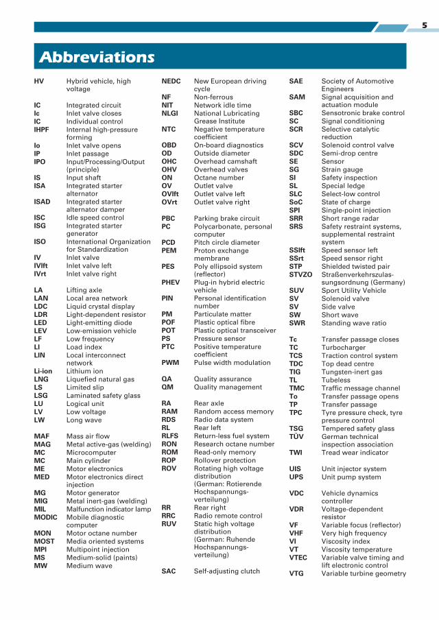
HV Hybrid vehicle, high voltage
IC Integrated circuit
Ic Inlet valve closes
IC Individual control
IHPF Internal high-pressure forming
Io Inlet valve opens
IP Inlet passage
IPO Input/Processing/Output (principle)
IS Input shaft
ISA Integrated starter alternator
ISAD Integrated starter alternator damper
ISC Idle speed control
ISG Integrated starter generator
ISO International Organization for Standardization
IV Inlet valve
IVlft Inlet valve left
IVrt Inlet valve right
LA Lifting axle
LAN Local area network
LDC Liquid crystal display
LDR Light-dependent resistor
LED Light-emitting diode
LEV Low-emission vehicle
LF Low frequency
LI Load index
LIN Local interconnect network
Li-ion Lithium ion
LNG Liquefied natural gas
LS Limited slip
LSG Laminated safety glass
LU Logical unit
LV Low voltage
LW Long wave
MAF Mass air flow
MAG Metal active-gas (welding)
MC Microcomputer
MC Main cylinder
ME Motor electronics
MED Motor electronics direct injection
MG Motor generator
MIG Metal inert-gas (welding)
MIL Malfunction indicator lamp
MODIC Mobile diagnostic computer
MON Motor octane number
MOST Media oriented systems
MPI Multipoint injection
MS Medium-solid (paints)
MW Medium wave
NEDC New European driving cycle
NF Non-ferrous
NIT Network idle time
NLGI National Lubricating Grease Institute
NTC Negative temperature coefficient
OBD On-board diagnostics
OD Outside diameter
OHC Overhead camshaft
OHV Overhead valves
ON Octane number
OV Outlet valve
OVlft Outlet valve left
OVrt Outlet valve right
PBC Parking brake circuit
PC Polycarbonate, personal computer
PCD Pitch circle diameter
PEM Proton exchange membrane
PES Poly ellipsoid system (reflector)
PHEV Plug-in hybrid electric vehicle
PIN Personal identification number
PM Particulate matter
POF Plastic optical fibre
POT Plastic optical transceiver
PS Pressure sensor
PTC Positive temperature coefficient
PWM Pulse width modulation
QA Quality assurance
QM Quality management
RA Rear axle
RAM Random access memory
RDS Radio data system
RL Rear left
RLFS Return-less fuel system
RON Research octane number
ROM Read-only memory
ROP Rollover protection
ROV Rotating high voltage distribution (German: Rotierende Hochspannungs-verteilung)
RR Rear right
RRC Radio remote control
RUV Static high voltage distribution (German: Ruhende Hochspannungs-verteilung)
SAC Self-adjusting clutch
SAE Society of Automotive Engineers
SAM Signal acquisition and actuation module
SBC Sensotronic brake control
SC Signal conditioning
SCR Selective catalytic reduction
SCV Solenoid control valve
SDC Semi-drop centre
SE Sensor
SG Strain gauge
SI Safety inspection
SL Special ledge
SLC Select-low control
SoC State of charge
SPI Single-point injection
SRR Short range radar
SRS Safety restraint systems, supplemental restraint system
SSlft Speed sensor left
SSrt Speed sensor right
STP Shielded twisted pair
STVZO Straßenverkehrs zulas-sungs ordnung (Germany)
SUV Sport Utility Vehicle
SV Solenoid valve
SV Side valve
SW Short wave
SWR Standing wave ratio
Tc Transfer passage closes
TC Turbocharger
TCS Traction control system
TDC Top dead centre
TIG Tungsten-inert gas
TL Tubeless
TMC Traffic message channel
To Transfer passage opens
TP Transfer passage
TPC Tyre pressure check, tyre pressure control
TSG Tempered safety glass
TÜV German technical inspection association
TWI Tread wear indicator
UIS Unit injector system
UPS Unit pump system
VDC Vehicle dynamics controller
VDR Voltage-dependent resistor
VF Variable focus (reflector)
VHF Very high frequency
VI Viscosity index
VT Viscosity temperature
VTEC Variable valve timing and lift electronic control
VTG Variable turbine geometry
Abbreviations

6 Contributing companies
Alfa-Romeo AutomobilesMilan, Italy
ALLIGATOR Ventilfabrik GmbHGiengen/Brenz, Germany
Aprilia Motorrad-VertriebDüsseldorf, Germany
Aral AG, Bochum, Germany
Audatex Deutschland, Minden, Germany
Audi AG, Ingolstadt – Neckarsulm, Germany
Autokabel, Hausen, Germany
Autoliv, Oberschleißheim, Germany
G. Auwärter GmbH & Co(Neoplan) Stuttgart, Germany
BBS Kraftfahrzeugtechnik AG, Schiltach, Germany
BEHR GmbH & Co, Stuttgart, Germany
Beissbarth GmbH, Automobil Service-geräte, Munich, Germany
BERU, Ludwigsburg, Germany
Aug. Bilstein GmbH & Co KGEnnepetal, Germany
Boge GmbH, Eitdorf/Sieg, Germany
Robert Bosch GmbH, Stuttgart, Germany
Bostik GmbHOberursel/Taunus, Germany
BLACK HAWK, Kehl, Germany
BMW Bayerische Motoren-Werke AGMunich/Berlin, Germany
CAR-OLINER, Kungsör, Sweden
CAR BENCH INTERNATIONAL.S.P.A.Massa, Italy
Continental Teves AG & Co, OHGFrankfurt, Germany
Celette GmbH, Kehl, Germany
Citroen Deutschland AGCologne, Germany
Dataliner RichtsystemeAhlerstedt, Germany
Deutsche BP AG, Hamburg, Germany
DUNLOP GmbH & Co KGHanau/Main, Germany
ESSO AG, Hamburg, Germany
FAG Kugelfischer Georg Schäfer KG aAEbern, Germany
J. Eberspächer, Esslingen, Germany
EMM Motoren Service, Lindau, Germany
Ford-Werke AG, Cologne, Germany
Carl FreudenbergWeinheim/Bergstraße, Germany
GKN Löbro, Offenbach/Main, Germany
Getrag Getriebe- und ZahnradfarbrikLudwigsburg, Germany
Girling-Bremsen GmbHKoblenz, Germany
Glasurit GmbHMünster/Westphalia, Germany
Globaljig, Deutschland GmbHCloppenburg, Germany
Glyco-Metall-Werke B.V. & Co KGWiesbaden/Schierstein, Germany
Goetze AG, Burscheid, Germany
Grau-Bremse, Heidelberg, Germany
Gutmann Messtechnik GmbHIhringen, Germany
Hazet-Werk, Hermann ZerverRemscheid, Germany
HAMEG GmbH, Frankfurt/Main, Germany
Hella KG, Hueck & CoLippstadt, Germany
Hengst Filterwerke, Nienkamp, Germany
Fritz Hintermayr, Bing-Vergaser-FabrikNuremberg, Germany
HITACHI Sales Europa GmbHDüsseldorf, Germany
HONDA DEUTSCHLAND GMBHOffenbach/Main, Germany
Hunger Maschinenfabrik GmbHMunich and Kaufering, Germany
IBM Deutschland, Böblingen, Germany
IVECO-Magirus AG, Neu-Ulm, Germany
ITT Automotive (ATE, VDO, MOTO-METER, SWF, KONI, Kienzle)
Frankfurt/Main, Germany
IXION MaschinenfabrikOtto Häfner GmbH & Co
Hamburg-Wandsbeck, Germany
Jurid-Werke, Essen, Germany
Alfred Kärcher GmbH & Co. KGWinnenden, Germany
Kawasaki-Motoren GmbHFriedrichsdorf, Germany
Knecht Filterwerke GmbHStuttgart, Germany
Knorr-Bremse GmbH, Munich, Germany
Kolbenschmidt AG, Neckarsulm, Germany
KS Gleitlager GmbHSt. Leon-Rot, Germany
KTM Sportmotorcycles AGMattighofen, Austria
Kühnle, Kopp und Kausch AGFrankenthal/Palatinate, Germany
Lemmerz-Werke, Königswinter, Germany
LuK GmbH, Bühl/Baden, Germany
MAHLE GmbH, Stuttgart, Germany
Mannesmann Sachs AGSchweinfurt, Germany
Mann und Hummel, FilterwerkeLudwigsburg, Germany
MAN MaschinenfabrikAugsburg-Nürnberg AG
Munich, Germany
Mazda Motors Deutschland GmbHLeverkusen, Germany
MCC – Mikro Compact Car GmbHBöblingen, Germany
Messer-Griesheim GmbHFrankfurt/Main, Germany
Mercedes Benz, Stuttgart, Germany
Metzeler Reifen GmbHMunich, Germany
Michelin Reifenwerke KGaAKarlsruhe, Germany
Microsoft GmbHUnterschleißheim, Germany
Mitsubishi Electric Europe B.V.Ratingen, Germany
Mitsubishi MMC, Trebur, Germany
MOBIL OIL AG, Hamburg, Germany
NGK/NTK Europe GmbHRatingen, Germany
Adam Opel AG, Rüsselsheim, Germany
OSRAM AG, Munich, Germany
OMV AG, Vienna, Austria
Oxigin-, Carmanin-LM-Räder, Unterensingen, Germany
Peugeot Deutschland GmbHSaarbrücken, Germany
Pierburg GmbH, Neuss, Germany
Pirelli AG, Höchst im Odenwald, Germany
Dr. Ing. h.c. F. Porsche AGStuttgart-Zuffenhausen, Germany
Renault Nissan Deutschland AGBrühl, Germany
Samsung Electronics GmbHCologne, Germany
SATA Farbspritztechnik GmbH & CoKornwestheim, Germany
SCANIA Deutschland GmbHKoblenz, Germany
SEKURIT SAINT-GOBAINDeutschland GmbH, Aachen, Germany
Schäffler Automotive, Langen, Germany
Siemens AG, Munich, Germany
SKF Kugellagerfabriken GmbHSchweinfurt, Germany
Snap-on/SNA Germany,Hohenstein-Ernstthal, Germany
SOLO Kleinmotoren GmbHSindelfingen, Germany
SONAX GmbH, Neuburg, Germany
Stahlwille E. WilleWuppertal, Germany
Steyr-Daimler-Puch AGGraz, Austria
Subaru Deutschland GmbHFriedberg, Germany
SUN Elektrik DeutschlandMettmann, Germany
Suzuki GmbHOberschleißheim/Heppenheim, Germany
Technolit GmbH, Großlüder, Germany
Telma Retarder Deutschland GmbHLudwigsburg, Germany
Temic Elektronik, Nuremberg, Germany
TOYOTA Deutschland GmbHCologne, Germany
UNIWHEELS GmbHBad Dürkheim, Germany
VARTA Autobatterien GmbHHannover, Germany
Vereinigte Motor-Verlage GmbH & Co KGStuttgart, Germany
ViewSonic Central EuropeWillich, Germany
Voith GmbH & Co KGHeidenheim, Germany
Volkswagen AG, Wolfsburg, Germany
Volvo Deutschland GmbHBrühl, Germany
Wabco Westinghouse GmbHHannover, Germany
Webasto GmbH, Stockdorf, Germany
Yamaha Motor Deutschland GmbHNeuss, Germany
ZF Getriebe GmbHSaarbrücken, Germany
ZF Sachs AG, Schweinfurt, Germany
ZF Zahnradfabrik Friedrichshafen AGFriedrichshafen/Schwäbisch Gmünd,
Germany
We wish to thank the companies listed below for providing technical advice, information, photographs and
illustrations.
7
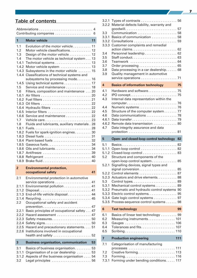
Table of contents
Abbreviations . . . . . . . . . . . . . . . . . . . . . . . . . . . . . . 4
Contributing companies . . . . . . . . . . . . . . . . . . . . 6
1 Motor vehicle 11
1.1 Evolution of the motor vehicle . . . . . . . . . . 11
1.2 Motor vehicle classifications. . . . . . . . . . . . 12
1.3 Design of the motor vehicle . . . . . . . . . . . . 12
1.4 The motor vehicle as technical system . . . 13
1.4.1 Technical systems . . . . . . . . . . . . . . . . . . . . 13
1.4.2 Motor vehicle system . . . . . . . . . . . . . . . . . 13
1.4.3 Subsystems in the motor vehicle . . . . . . . 15
1.4.4 Classifications of technical systems and
subsystems by processing mode. . . . . . . . 16
1.4.5 Using technical systems . . . . . . . . . . . . . . . 17
1.5 Service and maintenance . . . . . . . . . . . . . . 18
1.6 Filters, composition and maintenance . . . 20
1.6.1 Air filters . . . . . . . . . . . . . . . . . . . . . . . . . . . . 20
1.6.2 Fuel filters . . . . . . . . . . . . . . . . . . . . . . . . . . . 21
1.6.3 Oil filters . . . . . . . . . . . . . . . . . . . . . . . . . . . . 22
1.6.4 Hydraulic filters . . . . . . . . . . . . . . . . . . . . . . 22
1.6.5 Interior filters . . . . . . . . . . . . . . . . . . . . . . . . 22
1.6.6 Service and maintenance . . . . . . . . . . . . . . 22
1.7 Vehicle care. . . . . . . . . . . . . . . . . . . . . . . . . . 23
1.8 Fluids and lubricants, auxiliary materials . 28
1.8.1 Fuels. . . . . . . . . . . . . . . . . . . . . . . . . . . . . . . . 28
1.8.2 Fuels for spark-ignition engines . . . . . . . . . 30
1.8.3 Diesel fuels . . . . . . . . . . . . . . . . . . . . . . . . . . 31
1.8.4 Plant-based fuels . . . . . . . . . . . . . . . . . . . . . 32
1.8.5 Gaseous fuels . . . . . . . . . . . . . . . . . . . . . . . . 34
1.8.6 Oils and lubricants . . . . . . . . . . . . . . . . . . . . 34
1.8.7 Antifreeze . . . . . . . . . . . . . . . . . . . . . . . . . . . 39
1.8.8 Refrigerant . . . . . . . . . . . . . . . . . . . . . . . . . . 40
1.8.9 Brake fluid . . . . . . . . . . . . . . . . . . . . . . . . . . . 40
2 Environmental protection, occupational safety 41
2.1 Environmental protection in automotive
service operations . . . . . . . . . . . . . . . . . . . . 41
2.1.1 Environmental pollution . . . . . . . . . . . . . . . 41
2.1.2 Disposal. . . . . . . . . . . . . . . . . . . . . . . . . . . . . 41
2.1.3 End-of-life vehicle disposal . . . . . . . . . . . . . 44
2.1.4 Recycling. . . . . . . . . . . . . . . . . . . . . . . . . . . . 45
2.2 Occupational safety and accident
prevention. . . . . . . . . . . . . . . . . . . . . . . . . . . 47
2.2.1 Basic principles of occupational safety . . . 47
2.2.2 Hazard assessment . . . . . . . . . . . . . . . . . . . 47
2.2.3 Safety measures. . . . . . . . . . . . . . . . . . . . . . 50
2.2.4 Safety signs. . . . . . . . . . . . . . . . . . . . . . . . . . 50
2.2.5 Hazard and precautionary statements. . . . 51
2.2.6 Institutions involved in occupational
health and safety . . . . . . . . . . . . . . . . . . . . . 52
3 Business organisation, communication 53
3.1 Basics of business organisation. . . . . . . . . 53
3.1.1 Organisation of a car dealership . . . . . . . . 53
3.1.2 Aspects of the business organisation . . . . 54
3.2 Legal principles . . . . . . . . . . . . . . . . . . . . . . 56
3.2.1 Types of contracts . . . . . . . . . . . . . . . . . . . . 56
3.2.2 Material defects liability, warranty and
goodwill. . . . . . . . . . . . . . . . . . . . . . . . . . . . . 57
3.3 Communication . . . . . . . . . . . . . . . . . . . . . . 58
3.3.1 Basics of communication . . . . . . . . . . . . . . 58
3.3.2 Consultations . . . . . . . . . . . . . . . . . . . . . . . . 59
3.3.3 Customer complaints and remedial
action claims. . . . . . . . . . . . . . . . . . . . . . . . . 62
3.4 Personnel leadership . . . . . . . . . . . . . . . . . . 62
3.5 Staff conduct. . . . . . . . . . . . . . . . . . . . . . . . . 63
3.6 Teamwork . . . . . . . . . . . . . . . . . . . . . . . . . . 64
3.7 Order processing . . . . . . . . . . . . . . . . . . . . . 65
3.8 Data processing in a car dealership. . . . . . 68
3.9 Quality management in automotive
service operations . . . . . . . . . . . . . . . . . . . . 71
4 Basics of information technology 75
4.1 Hardware and software. . . . . . . . . . . . . . . . 75
4.2 IPO concept. . . . . . . . . . . . . . . . . . . . . . . . . . 75
4.3 Internal data representation within the
computer. . . . . . . . . . . . . . . . . . . . . . . . . . . . 76
4.4 Numeric systems . . . . . . . . . . . . . . . . . . . . . 76
4.5 Structure of the computer system . . . . . . . 77
4.6 Data communications . . . . . . . . . . . . . . . . . 78
4.6.1 Data transfer . . . . . . . . . . . . . . . . . . . . . . . . . 79
4.6.2 Remote data transmission . . . . . . . . . . . . . 80
4.7 Data integrity assurance and data
protection . . . . . . . . . . . . . . . . . . . . . . . . . . . 81
5 Open- and closed-loop control technology 82
5.1 Basics. . . . . . . . . . . . . . . . . . . . . . . . . . . . . . . 82
5.1.1 Open-loop control . . . . . . . . . . . . . . . . . . . . 82
5.1.2 Closed-loop control . . . . . . . . . . . . . . . . . . . 83
5.2 Structure and components of the
open-loop control system . . . . . . . . . . . . . . 85
5.2.1 Signalling devices, signal types and
signal conversion . . . . . . . . . . . . . . . . . . . . . 85
5.2.2 Control elements . . . . . . . . . . . . . . . . . . . . . 87
5.2.3 Actuators and drive elements. . . . . . . . . . . 88
5.3 Control types. . . . . . . . . . . . . . . . . . . . . . . . . 89
5.3.1 Mechanical control systems . . . . . . . . . . . . 89
5.3.2 Pneumatic and hydraulic control systems 90
5.3.3 Electric control systems. . . . . . . . . . . . . . . . 95
5.3.4 Gate logic control systems . . . . . . . . . . . . . 97
5.3.5 Process-sequence control systems . . . . . . 98
6 Test technology 99
6.1 Basics of linear test technology . . . . . . . . . 99
6.2 Measuring instruments . . . . . . . . . . . . . . . 101
6.3 Gauges . . . . . . . . . . . . . . . . . . . . . . . . . . . . 106
6.4 Tolerances and fits. . . . . . . . . . . . . . . . . . . 107
6.5 Scribing . . . . . . . . . . . . . . . . . . . . . . . . . . . . 110
7 Production engineering 111
7.1 Categorisation of manufacturing
processes . . . . . . . . . . . . . . . . . . . . . . . . . . 111
7.2 Creative forming. . . . . . . . . . . . . . . . . . . . . 113
7.3 Forming. . . . . . . . . . . . . . . . . . . . . . . . . . . . 116
7.3.1 Forming under bending conditions . . . . . 117
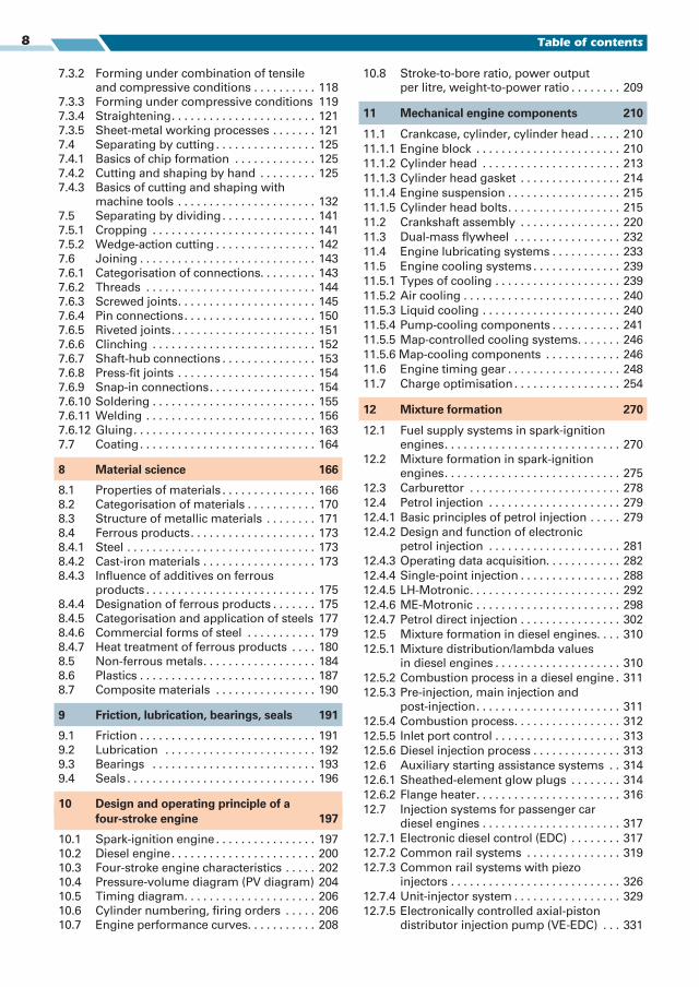
8 Table of contents
7.3.2 Forming under combination of tensile
and compressive conditions . . . . . . . . . . 118
7.3.3 Forming under compressive conditions 119
7.3.4 Straightening. . . . . . . . . . . . . . . . . . . . . . . 121
7.3.5 Sheet-metal working processes . . . . . . . 121
7.4 Separating by cutting . . . . . . . . . . . . . . . . 125
7.4.1 Basics of chip formation . . . . . . . . . . . . . 125
7.4.2 Cutting and shaping by hand . . . . . . . . . 125
7.4.3 Basics of cutting and shaping with
machine tools . . . . . . . . . . . . . . . . . . . . . . 132
7.5 Separating by dividing. . . . . . . . . . . . . . . 141
7.5.1 Cropping . . . . . . . . . . . . . . . . . . . . . . . . . . 141
7.5.2 Wedge-action cutting . . . . . . . . . . . . . . . . 142
7.6 Joining . . . . . . . . . . . . . . . . . . . . . . . . . . . . 143
7.6.1 Categorisation of connections. . . . . . . . . 143
7.6.2 Threads . . . . . . . . . . . . . . . . . . . . . . . . . . . 144
7.6.3 Screwed joints. . . . . . . . . . . . . . . . . . . . . . 145
7.6.4 Pin connections. . . . . . . . . . . . . . . . . . . . . 150
7.6.5 Riveted joints. . . . . . . . . . . . . . . . . . . . . . . 151
7.6.6 Clinching . . . . . . . . . . . . . . . . . . . . . . . . . . 152
7.6.7 Shaft-hub connections . . . . . . . . . . . . . . . 153
7.6.8 Press-fit joints . . . . . . . . . . . . . . . . . . . . . . 154
7.6.9 Snap-in connections. . . . . . . . . . . . . . . . . 154
7.6.10 Soldering . . . . . . . . . . . . . . . . . . . . . . . . . . 155
7.6.11 Welding . . . . . . . . . . . . . . . . . . . . . . . . . . . 156
7.6.12 Gluing. . . . . . . . . . . . . . . . . . . . . . . . . . . . . 163
7.7 Coating. . . . . . . . . . . . . . . . . . . . . . . . . . . . 164
8 Material science 166
8.1 Properties of materials . . . . . . . . . . . . . . . 166
8.2 Categorisation of materials . . . . . . . . . . . 170
8.3 Structure of metallic materials . . . . . . . . 171
8.4 Ferrous products. . . . . . . . . . . . . . . . . . . . 173
8.4.1 Steel . . . . . . . . . . . . . . . . . . . . . . . . . . . . . . 173
8.4.2 Cast-iron materials . . . . . . . . . . . . . . . . . . 173
8.4.3 Influence of additives on ferrous
products . . . . . . . . . . . . . . . . . . . . . . . . . . . 175
8.4.4 Designation of ferrous products . . . . . . . 175
8.4.5 Categorisation and application of steels 177
8.4.6 Commercial forms of steel . . . . . . . . . . . 179
8.4.7 Heat treatment of ferrous products . . . . 180
8.5 Non-ferrous metals. . . . . . . . . . . . . . . . . . 184
8.6 Plastics . . . . . . . . . . . . . . . . . . . . . . . . . . . . 187
8.7 Composite materials . . . . . . . . . . . . . . . . 190
9 Friction, lubrication, bearings, seals 191
9.1 Friction . . . . . . . . . . . . . . . . . . . . . . . . . . . . 191
9.2 Lubrication . . . . . . . . . . . . . . . . . . . . . . . . 192
9.3 Bearings . . . . . . . . . . . . . . . . . . . . . . . . . . 193
9.4 Seals . . . . . . . . . . . . . . . . . . . . . . . . . . . . . . 196
10 Design and operating principle of a four-stroke engine 197
10.1 Spark-ignition engine . . . . . . . . . . . . . . . . 197
10.2 Diesel engine. . . . . . . . . . . . . . . . . . . . . . . 200
10.3 Four-stroke engine characteristics . . . . . 202
10.4 Pressure-volume diagram (PV diagram) 204
10.5 Timing diagram. . . . . . . . . . . . . . . . . . . . . 206
10.6 Cylinder numbering, firing orders . . . . . 206
10.7 Engine performance curves. . . . . . . . . . . 208
10.8 Stroke-to-bore ratio, power output
per litre, weight-to-power ratio . . . . . . . . 209
11 Mechanical engine components 210
11.1 Crankcase, cylinder, cylinder head . . . . . 210
11.1.1 Engine block . . . . . . . . . . . . . . . . . . . . . . . 210
11.1.2 Cylinder head . . . . . . . . . . . . . . . . . . . . . . 213
11.1.3 Cylinder head gasket . . . . . . . . . . . . . . . . 214
11.1.4 Engine suspension . . . . . . . . . . . . . . . . . . 215
11.1.5 Cylinder head bolts. . . . . . . . . . . . . . . . . . 215
11.2 Crankshaft assembly . . . . . . . . . . . . . . . . 220
11.3 Dual-mass flywheel . . . . . . . . . . . . . . . . . 232
11.4 Engine lubricating systems . . . . . . . . . . . 233
11.5 Engine cooling systems . . . . . . . . . . . . . . 239
11.5.1 Types of cooling . . . . . . . . . . . . . . . . . . . . 239
11.5.2 Air cooling . . . . . . . . . . . . . . . . . . . . . . . . . 240
11.5.3 Liquid cooling . . . . . . . . . . . . . . . . . . . . . . 240
11.5.4 Pump-cooling components . . . . . . . . . . . 241
11.5.5 Map-controlled cooling systems. . . . . . . 246
11.5.6 Map-cooling components . . . . . . . . . . . . 246
11.6 Engine timing gear . . . . . . . . . . . . . . . . . . 248
11.7 Charge optimisation . . . . . . . . . . . . . . . . . 254
12 Mixture formation 270
12.1 Fuel supply systems in spark-ignition
engines. . . . . . . . . . . . . . . . . . . . . . . . . . . . 270
12.2 Mixture formation in spark-ignition
engines. . . . . . . . . . . . . . . . . . . . . . . . . . . . 275
12.3 Carburettor . . . . . . . . . . . . . . . . . . . . . . . . 278
12.4 Petrol injection . . . . . . . . . . . . . . . . . . . . . 279
12.4.1 Basic principles of petrol injection . . . . . 279
12.4.2 Design and function of electronic
petrol injection . . . . . . . . . . . . . . . . . . . . . 281
12.4.3 Operating data acquisition. . . . . . . . . . . . 282
12.4.4 Single-point injection . . . . . . . . . . . . . . . . 288
12.4.5 LH-Motronic. . . . . . . . . . . . . . . . . . . . . . . . 292
12.4.6 ME-Motronic . . . . . . . . . . . . . . . . . . . . . . . 298
12.4.7 Petrol direct injection . . . . . . . . . . . . . . . . 302
12.5 Mixture formation in diesel engines. . . . 310
12.5.1 Mixture distribution/lambda values
in diesel engines . . . . . . . . . . . . . . . . . . . . 310
12.5.2 Combustion process in a diesel engine . 311
12.5.3 Pre-injection, main injection and
post-injection. . . . . . . . . . . . . . . . . . . . . . . 311
12.5.4 Combustion process. . . . . . . . . . . . . . . . . 312
12.5.5 Inlet port control . . . . . . . . . . . . . . . . . . . . 313
12.5.6 Diesel injection process . . . . . . . . . . . . . . 313
12.6 Auxiliary starting assistance systems . . 314
12.6.1 Sheathed-element glow plugs . . . . . . . . 314
12.6.2 Flange heater. . . . . . . . . . . . . . . . . . . . . . . 316
12.7 Injection systems for passenger car
diesel engines . . . . . . . . . . . . . . . . . . . . . . 317
12.7.1 Electronic diesel control (EDC) . . . . . . . . 317
12.7.2 Common rail systems . . . . . . . . . . . . . . . 319
12.7.3 Common rail systems with piezo
injectors . . . . . . . . . . . . . . . . . . . . . . . . . . . 326
12.7.4 Unit-injector system . . . . . . . . . . . . . . . . . 329
12.7.5 Electronically controlled axial-piston
distributor injection pump (VE-EDC) . . . 331
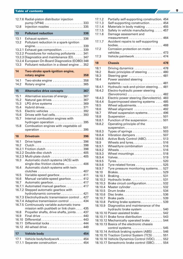
9Table of contents
12.7.6 Radial-piston distributor injection
pump (VP44) . . . . . . . . . . . . . . . . . . . . . . . 333
12.8 Injection nozzles . . . . . . . . . . . . . . . . . . . . 335
13 Pollutant reduction 336
13.1 Exhaust system. . . . . . . . . . . . . . . . . . . . . 336
13.2 Pollutant reduction in a spark-ignition
engine. . . . . . . . . . . . . . . . . . . . . . . . . . . . . 339
13.2.1 Exhaust gas composition. . . . . . . . . . . . . 339
13.2.2 Procedures for reducing pollutants . . . . 341
13.2.3 Diagnostics and maintenance (EI). . . . . . 347
13.2.4 European On-Board Diagnostics (EOBD) 348
13.3 Pollutant reduction in a diesel engine . . 352
14 Two-stroke spark-ignition engine, rotary engine 358
14.1 Two-stroke engine . . . . . . . . . . . . . . . . . . 358
14.2 Rotary engine . . . . . . . . . . . . . . . . . . . . . . 365
15 Alternative drive concepts 367
15.1 Alternative sources of energy . . . . . . . . . 367
15.2 Natural gas drives. . . . . . . . . . . . . . . . . . . 367
15.3 LPG drive systems . . . . . . . . . . . . . . . . . . 369
15.4 Hybrid drives . . . . . . . . . . . . . . . . . . . . . . . 371
15.5 Electric vehicles . . . . . . . . . . . . . . . . . . . . 392
15.6 Drives with fuel cells. . . . . . . . . . . . . . . . . 393
15.7 Internal combustion engines with
hydrogen operation . . . . . . . . . . . . . . . . . 395
15.8 Combustion engines with vegetable oil
operation . . . . . . . . . . . . . . . . . . . . . . . . . . 395
16 Drivetrain 396
16.1 Drive types . . . . . . . . . . . . . . . . . . . . . . . . 396
16.2 Clutch . . . . . . . . . . . . . . . . . . . . . . . . . . . . . 398
16.2.1 Friction clutch . . . . . . . . . . . . . . . . . . . . . . 398
16.2.2 Double-disc clutch . . . . . . . . . . . . . . . . . . 405
16.2.3 Multi-plate clutch . . . . . . . . . . . . . . . . . . . 405
16.3 Automatic clutch systems (ACS) with
single-disc friction clutches . . . . . . . . . . . 406
16.4 Automatic clutch systems with twin
clutches . . . . . . . . . . . . . . . . . . . . . . . . . . . 407
16.5 Variable-speed gearbox . . . . . . . . . . . . . . 411
16.6 Manual variable-speed gearbox . . . . . . . 412
16.7 Automatic gearbox . . . . . . . . . . . . . . . . . . 417
16.7.1 Automated manual gearbox . . . . . . . . . . 417
16.7.2 Stepped automatic gearbox with
hydrodynamic converter . . . . . . . . . . . . . 421
16.7.3 Electrohydraulic transmission control . . 427
16.7.4 Adaptive transmission control . . . . . . . . 434
16.7.5 Continuously variable automatic trans-
mission with pushbelt or link chain . . . . 435
16.8 Propeller shafts, drive shafts, joints . . . . 437
16.9 Final drive . . . . . . . . . . . . . . . . . . . . . . . . . 440
16.10 Differential . . . . . . . . . . . . . . . . . . . . . . . . . 443
16.11 Differential locks . . . . . . . . . . . . . . . . . . . . 444
16.12 All-wheel drive . . . . . . . . . . . . . . . . . . . . . 449
17 Vehicle body 454
17.1 Vehicle body/bodywork . . . . . . . . . . . . . . 454
17.1.1 Separate construction . . . . . . . . . . . . . . . 454
17.1.2 Partially self-supporting construction. 454
17.1.3 Self-supporting construction. . . . . . . . 454
17.1.4 Materials in body making . . . . . . . . . . 455
17.1.5 Safety in vehicle manufacturing . . . . . 457
17.1.6 Damage assessment and
measurement . . . . . . . . . . . . . . . . . . . . 464
17.1.7 Accident repairs to self-supporting
bodies. . . . . . . . . . . . . . . . . . . . . . . . . . . 468
17.2 Corrosion protection on motor
vehicles. . . . . . . . . . . . . . . . . . . . . . . . . . 473
17.3 Vehicle paintwork . . . . . . . . . . . . . . . . . 474
18 Chassis 478
18.1 Driving dynamics . . . . . . . . . . . . . . . . . 478
18.2 Basic principles of steering . . . . . . . . . 480
18.3 Steering gear . . . . . . . . . . . . . . . . . . . . 481
18.4 Power assisted steering
systems . . . . . . . . . . . . . . . . . . . . . . . . . 481
18.4.1 Hydraulic rack-and-pinion steering. . . 481
18.4.2 Electro-hydraulic power steering
(Servotronic) . . . . . . . . . . . . . . . . . . . . . 482
18.4.3 Electric power steering (Servolectric). 483
18.4.4 Superimposed steering systems . . . . 485
18.5 Wheel adjustments. . . . . . . . . . . . . . . . 489
18.6 Wheel alignment . . . . . . . . . . . . . . . . . 492
18.7 Wheel suspension systems . . . . . . . . . 496
18.8 Suspension . . . . . . . . . . . . . . . . . . . . . . 501
18.8.1 Function of the suspension . . . . . . . . . 501
18.8.2 Operating principle of the
suspension. . . . . . . . . . . . . . . . . . . . . . . 501
18.8.3 Types of springs . . . . . . . . . . . . . . . . . . 503
18.8.4 Vibration dampers . . . . . . . . . . . . . . . . 507
18.8.5 Active Body Control (ABC). . . . . . . . . . 513
18.9 Wheels and tyres. . . . . . . . . . . . . . . . . . 516
18.9.1 Wheel/tyre combination . . . . . . . . . . . 516
18.9.2 Wheels . . . . . . . . . . . . . . . . . . . . . . . . . . 516
18.9.3 Wheel mountings . . . . . . . . . . . . . . . . . 518
18.9.4 Valves . . . . . . . . . . . . . . . . . . . . . . . . . . . 519
18.9.5 Tyres. . . . . . . . . . . . . . . . . . . . . . . . . . . . 520
18.9.6 Tyre-related forces . . . . . . . . . . . . . . . . 525
18.9.7 Tyre pressure monitoring systems. . . 527
18.10 Brakes. . . . . . . . . . . . . . . . . . . . . . . . . . . 529
18.10.1 Braking . . . . . . . . . . . . . . . . . . . . . . . . . . 531
18.10.2 Hydraulic brake . . . . . . . . . . . . . . . . . . . 531
18.10.3 Brake circuit configuration. . . . . . . . . . 532
18.10.4 Master cylinder . . . . . . . . . . . . . . . . . . . 532
18.10.5 Drum brake . . . . . . . . . . . . . . . . . . . . . . 534
18.10.6 Disc brake. . . . . . . . . . . . . . . . . . . . . . . . 536
18.10.7 Brake pads . . . . . . . . . . . . . . . . . . . . . . . 539
18.10.8 Parking brake systems . . . . . . . . . . . . . 539
18.10.9 Diagnostics and maintenance of the
hydraulic brake system . . . . . . . . . . . . 540
18.10.10 Power-assisted brake . . . . . . . . . . . . . . 542
18.10.11 Brake force distribution . . . . . . . . . . . . 543
18.10.12 Mechanically operated brake . . . . . . . 544
18.10.13 Basics of the electronic chassis
control systems. . . . . . . . . . . . . . . . . . . 545
18.10.14 Antilock braking system (ABS) . . . . . . 546
18.10.15 Traction Control System (TCS) . . . . . . 551
18.10.16 Vehicle Dynamics Control (VDC). . . . . 552
18.10.17 Sensotronic brake control (SBC). . . . . 554
10 Table of contents
18.10.18 Additional brake functions. . . . . . . . . . 554
18.10.19 Brake assist system (BAS) . . . . . . . . . . 555
18.10.20 Emergency Brake Assist (EBA),
Active Brake Assist (ABA) . . . . . . . . . . 555
19 Electrical engineering 556
19.1 General principles of electrical
engineering . . . . . . . . . . . . . . . . . . . . . . 556
19.1.1 Voltage . . . . . . . . . . . . . . . . . . . . . . . . . 557
19.1.2 Electrical current . . . . . . . . . . . . . . . . . . 557
19.1.3 Electrical resistance . . . . . . . . . . . . . . . 559
19.1.4 Ohm's Law. . . . . . . . . . . . . . . . . . . . . . . 561
19.1.5 Power, work, efficiency . . . . . . . . . . . . 561
19.1.6 Resistor circuits . . . . . . . . . . . . . . . . . . . 562
19.1.7 Measurements in electrical circuits . . 563
19.1.8 Properties of electrical current . . . . . . 571
19.1.9 Protection against the hazards of
electrical current . . . . . . . . . . . . . . . . . . 572
19.1.10 Voltage generation . . . . . . . . . . . . . . . . 574
19.1.11 Alternating voltage and
alternating current . . . . . . . . . . . . . . . . 576
19.1.12 Three-phase AC voltage and
three-phase current . . . . . . . . . . . . . . . 577
19.1.13 Magnetism. . . . . . . . . . . . . . . . . . . . . . . 577
19.1.14 Self-induction . . . . . . . . . . . . . . . . . . . . 579
19.1.15 Capacitor . . . . . . . . . . . . . . . . . . . . . . . . 580
19.1.16 Electrochemistry . . . . . . . . . . . . . . . . . . 580
19.1.17 Electronic components. . . . . . . . . . . . . 582
19.2 Applications of electrical
engineering . . . . . . . . . . . . . . . . . . . . . . 593
19.2.1 Wiring diagrams . . . . . . . . . . . . . . . . . . 593
19.2.2 Additional information and labelling
in circuit diagrams . . . . . . . . . . . . . . . . 595
19.2.3 Using current diagrams . . . . . . . . . . . . 596
19.2.4 Overall circuit diagram of a vehicle's
standard equipment . . . . . . . . . . . . . . . 597
19.2.5 Signal transmitters . . . . . . . . . . . . . . . . 605
19.2.6 Relays . . . . . . . . . . . . . . . . . . . . . . . . . . . 606
19.2.7 Lighting in the motor vehicle. . . . . . . . 608
19.2.8 Illuminators . . . . . . . . . . . . . . . . . . . . . . 609
19.2.9 Power supply. . . . . . . . . . . . . . . . . . . . . 617
19.2.10 Alternator . . . . . . . . . . . . . . . . . . . . . . . . 624
19.2.11 Vehicle electrical system management 633
19.2.12 Electric motors . . . . . . . . . . . . . . . . . . . 635
19.2.13 Ignition systems . . . . . . . . . . . . . . . . . . 642
19.2.14 Sensors . . . . . . . . . . . . . . . . . . . . . . . . . 659
19.2.15 High frequency technology . . . . . . . . . 663
19.2.16 Electromagnetic compatibility (EMC). 668
19.2.17 Data transmission in motor vehicles . 670
19.2.18 Measuring, testing, diagnostics . . . . . 684
20 Comfort and convenience technology 688
20.1 Ventilation, heating, ambient air,
air conditioning . . . . . . . . . . . . . . . . . . . 688
20.2 Anti-theft systems. . . . . . . . . . . . . . . . . 695
20.2.1 Vehicle immobilisers . . . . . . . . . . . . . . 695
20.2.2 Central locking system . . . . . . . . . . . . . 696
20.2.3 Passive access. . . . . . . . . . . . . . . . . . . . 699
20.2.4 Anti-theft alarm system (ATA). . . . . . . 701
20.3 Comfort and convenience systems . . 703
20.3.1 Convertible roof actuation . . . . . . . . . . 703
20.3.2 Luxury seats. . . . . . . . . . . . . . . . . . . . . . 704
20.3.3 Electronic windscreen wiper control . 705
20.3.4 Electrically adjustable exterior
mirrors . . . . . . . . . . . . . . . . . . . . . . . . . . 705
20.4 Advanced driver assistance systems . 706
20.4.1 Cruise control system. . . . . . . . . . . . . . 706
20.4.2 Adaptive cruise control (ACC) . . . . . . . 706
20.4.3 Park distance control (PDC) . . . . . . . . . 708
20.4.4 Parking assistance (Park Assist) . . . . . 708
20.4.5 Camera-assisted parking . . . . . . . . . . . 709
20.4.6 Lane change assist (lane change
warning, blind spot assist). . . . . . . . . . 709
20.4.7 Lane departure warning system
(Lane Keeping Assist, Lane Assist) . . . 710
20.5 Infotainment systems. . . . . . . . . . . . . . 710
20.5.1 Operating and travel data display. . . . 710
20.5.2 Navigation systems . . . . . . . . . . . . . . . 711
20.5.3 Mobile phone cradle with linked
hands-free system . . . . . . . . . . . . . . . . 712
21 Motorcycle technology 713
21.1 Types of motorcycle . . . . . . . . . . . . . . 713
21.2 Motorcycle engines . . . . . . . . . . . . . . . 716
21.3 Exhaust system . . . . . . . . . . . . . . . . . . . 716
21.4 Mixture formation. . . . . . . . . . . . . . . . . 717
21.5 Engine cooling. . . . . . . . . . . . . . . . . . . . 718
21.6 Engine lubrication. . . . . . . . . . . . . . . . . 718
21.7 Clutch . . . . . . . . . . . . . . . . . . . . . . . . . . . 719
21.8 Drivetrain . . . . . . . . . . . . . . . . . . . . . . . . 720
21.9 Electrical system . . . . . . . . . . . . . . . . . . 722
21.10 Riding dynamics . . . . . . . . . . . . . . . . . . 725
21.11 Motorcycle frames . . . . . . . . . . . . . . . . 726
21.12 Wheel location, suspension and
damping. . . . . . . . . . . . . . . . . . . . . . . . . 727
21.13 Brakes. . . . . . . . . . . . . . . . . . . . . . . . . . . 729
21.14 Wheels and tyres. . . . . . . . . . . . . . . . . . 731
22 Commercial vehicle technology 734
22.1 Categorisation . . . . . . . . . . . . . . . . . . . . 734
22.2 Commercial vehicle dimensions. . . . . 735
22.3 Permissible CV weights . . . . . . . . . . . . 735
22.4 Payload regulations . . . . . . . . . . . . . . . 735
22.5 Commercial vehicle (CV) engines . . . . 736
22.6 Injection systems for
CV diesel engines . . . . . . . . . . . . . . . . . 737
22.6.1 CV common rail system. . . . . . . . . . . . 738
22.6.2 Pump-line-nozzle system (PLN). . . . . . 743
22.6.3 Auxiliary starting assistance systems 744
22.6.4 Reduction of harmful emissions in
CV diesel engines . . . . . . . . . . . . . . . . . 744
22.7 Drivetrain . . . . . . . . . . . . . . . . . . . . . . . . 746
22.8 Chassis . . . . . . . . . . . . . . . . . . . . . . . . . . 749
22.8.1 Suspension . . . . . . . . . . . . . . . . . . . . . . 749
22.8.2 Wheels and tyres. . . . . . . . . . . . . . . . . . 752
22.8.3 Air brake system (brake system with
external power source). . . . . . . . . . . . . 753
22.9 Starting systems for
commercial vehicles . . . . . . . . . . . . . . 765
23 Keyword index 769
1
11
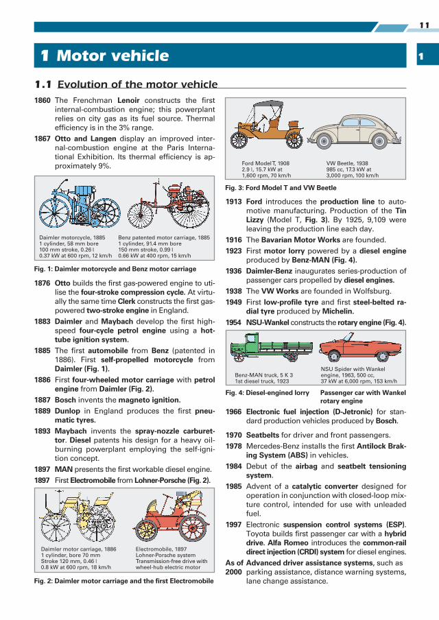
1860 The Frenchman Lenoir constructs the first
internal-combustion engine; this powerplant
relies on city gas as its fuel source. Thermal
efficiency is in the 3% range.
1867 Otto and Langen display an improved inter-
nal-combustion engine at the Paris Interna-
tional Exhibition. Its thermal efficiency is ap-
proximately 9%.
1876 Otto builds the first gas-powered engine to uti-
lise the four-stroke compression cycle. At virtu-
ally the same time Clerk constructs the first gas-
powered two-stroke engine in England.
1883 Daimler and Maybach develop the first high-
speed four-cycle petrol engine using a hot-tube ignition system.
1885 The first automobile from Benz (patented in
1886). First self-propelled motorcycle from
Daimler (Fig. 1).1886 First four-wheeled motor carriage with petrol
engine from Daimler (Fig. 2).1887 Bosch invents the magneto ignition.1889 Dunlop in England produces the first pneu-
matic tyres.1893 Maybach invents the spray-nozzle carburet-
tor. Diesel patents his design for a heavy oil-
burning powerplant employing the self-igni-
tion concept.
1897 MAN presents the first workable diesel engine.
1897 First Electromobile from Lohner-Porsche (Fig. 2).
1913 Ford introduces the production line to auto-
motive manufacturing. Production of the Tin Lizzy (Model T, Fig. 3). By 1925, 9,109 were
leaving the production line each day.
1916 The Bavarian Motor Works are founded.
1923 First motor lorry powered by a diesel engine
produced by Benz-MAN (Fig. 4).1936 Daimler-Benz inaugurates series-production of
passenger cars propelled by diesel engines.1938 The VW Works are founded in Wolfsburg.
1949 First low-profile tyre and first steel-belted ra-dial tyre produced by Michelin.
1954 NSU-Wankel constructs the rotary engine (Fig. 4).
1966 Electronic fuel injection (D-Jetronic) for stan-
dard production vehicles produced by Bosch.
1970 Seatbelts for driver and front passengers.
1978 Mercedes-Benz installs the first Antilock Brak-ing System (ABS) in vehicles.
1984 Debut of the airbag and seatbelt tensioning system.
1985 Advent of a catalytic converter designed for
operation in conjunction with closed-loop mix-
ture control, intended for use with unleaded
fuel.
1997 Electronic suspension control systems (ESP). Toyota builds first passenger car with a hybrid drive. Alfa Romeo introduces the common-rail direct injection (CRDI) system for diesel engines.
As of Advanced driver assistance systems, such as
2000 parking assistance, distance warning systems,
lane change assistance.
11 Motor vehicle Motor vehicle
1.1 Evolution of the motor vehicle
Daimler motorcycle, 18851 cylinder, 58 mm bore100 mm stroke, 0.26 —0.37 kW at 600 rpm, 12 km/h
Benz patented motor carriage, 18851 cylinder, 91.4 mm bore150 mm stroke, 0.99 —0.66 kW at 400 rpm, 15 km/h
Fig. 1: Daimler motorcycle and Benz motor carriage
Benz-MAN truck, 5 K 31st diesel truck, 1923
NSU Spider with Wankelengine, 1963, 500 cc,37 kW at 6,000 rpm, 153 km/h
Fig. 4: Diesel-engined lorry Passenger car with Wankel rotary engine
Fig. 2: Daimler motor carriage and the first Electromobile
Fig. 3: Ford Model T and VW Beetle
1
1 Motor vehicle12
1.2 Motor vehicle classifications
There are basically two vehicle classes: motor ve-
hicles and trailers. Motor vehicles always possess an
integral mechanical propulsion system.
Dual-track vehiclesMotor vehicles with more than two wheels can be
found in dual-track and multiple-track versions.
These include:
● Passenger cars. These are primarily intended for
use in transporting people, as well as their lug-
gage and other small cargo. They can also be
used to pull trailers. The number of seats, includ-
ing that of the driver, is restricted to nine.
● Commercial vehicles. These are designed to
transport people and cargo and for pulling trail-
ers. Passenger cars are not classified as commer-
cial vehicles.
Single-track vehiclesMotorcycles are single-track vehicles with 2 wheels.
A sidecar may be attached to the motorcycle, which
remains classified as such provided that the unladen
weight of the combination does not exceed 400 kg.
A motor cycle can also be employed to pull a trailer.
Single-track vehicles include:
● Motorcycles. These are equipped with permanent,
fixed-location components (fuel tank, engine) lo-
cated adjacent to the knees as well as footrests.
● Motor scooters. Since the operator's feet rest on
a floor board, there are no fixed components at
knee level on these vehicles.
● Bicycles with auxiliary motors. These vehicles
share the same salient features as bicycles, e.g.
pedals (mopeds, motorised bicycles, etc.).
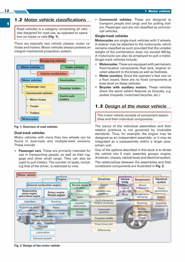
1.3 Design of the motor vehicle
The layout of the individual assemblies and their
relative positions is not governed by invariable
standards. Thus, for example, the engine may be
designed as an independent assembly, or it may be
integrated as a subassembly within a larger pow-
ertrain unit.
One of the options described in this book is to divide
the vehicle into 5 main assembly groups: engine,
drive train, chassis, vehicle body and electrical system.
The relationships between the assemblies and their
constituent components are illustrated in Fig. 2.
Road vehicles is a category comprising all vehi-
cles designed for road use, as opposed to opera-
tion on tracks or rails (Fig. 1).
Centre-axle trailers
Semitrailers
Motor vehicles
Vehicle combination
Motor vehicles
Passenger cars
Commercial vehicles
Motor buses
Motorcycles
Roadgoing vehicles
Drawbar trailers
Trailer vehicles
Trucks
Trailers
Fig. 1: Overview of road vehicles
Fig. 2: Design of the motor vehicle
Mixture preparation
Cooling
Lubrication
Exhaust system
Crankshaft drive
Cylinders
Internal-combustion engine
Reciprocatingpiston engine,
petrol/diesel engineRotary engineWankel engine
Housing
Rotor
Eccentric shaft
Engine Drivetrain Suspension
Powergenerators
Wheelsuspension
Suspensiondamping
Steering
Brakes
Battery
Wheels Tyres
Electricalconsumers
Electrical system
Electric motor
Stator
Rotor
Controlelectronics
Powersupply
Hydrodynamictorque converter
Clutch
Variable-ratiogearbox
Automaticgearbox
Propeller shafts
Final drive unit
Differential
Motor vehicle
Engine management
Vehicle body
Frame
Body
The motor vehicle consists of component assem-
blies and their individual components.
1
131 Motor vehicle
The smaller rectangle symbolises the system limit (hypothetical boundary) separating each individual
technical system from the other systems and/or the
surrounding environment.
1.4.2 Motor vehicle system
The motor vehicle is a complex technical system in
which various subsystems operate in harmony to
fulfil a defined function.
The function of the passenger car is to transport
people, while the function of the motor lorry, or truck,
is to carry cargo.
Operational units within the motor vehicleSystems designed to support operational processes
are combined in operational units (Fig. 1). Familiar-
ity with the processes performed in operational units
such as the engine, drivetrain, etc. can enhance our
1.4.1 Technical systems
Every machine forms a complete technical system.
The rectangle in the figure represents the technical
systems (Fig. 2).
Input and output variables are represented by ar-
rows. The number of arrows varies according to the
number of input and output variables.
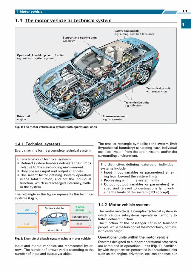
1.4 The motor vehicle as technical system
Safety equipment:e.g. airbag; seat-belt tensioner
e.g. suspension
e.g. drivetrain
Drive unit:engine
Open and closed-loop control units: e.g. antilock braking system
Support and bearing unit:e.g. body
e.g. suspensionTransmission unit:
Transmission unit:
Transmission unit:
Fig. 1: The motor vehicle as a system with operational units
The distinctive, defining features of individual
systems include:
● Input (input variables or parameters) enter-
ing from beyond the system limits
● Processing within the system limits
● Output (output variables or parameters) is-
sued and relayed to destinations lying out-
side the limits of the system (IPO concept)
System limit
Fuel
Motor vehicleKineticenergy
Exhaust gas
Heat
Air
Fig. 2: Example of a basic system using a motor vehicle
Characteristics of technical systems:
● Defined system borders delineate their limits
relative to the surrounding environment.
● They possess input and output channels.
● The salient factor defining system operation
is the total function, and not the individual
function, which is discharged internally, with-
in the system.
1
1 Motor vehicle14
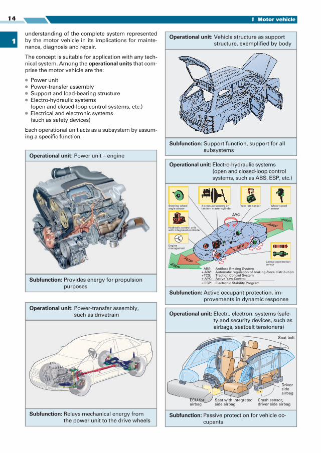
understanding of the complete system represented
by the motor vehicle in its implications for mainte-
nance, diagnosis and repair.
The concept is suitable for application with any tech-
nical system. Among the operational units that com-
prise the motor vehicle are the:
● Power unit
● Power-transfer assembly
● Support and load-bearing structure
● Electro-hydraulic systems
(open and closed-loop control systems, etc.)
● Electrical and electronic systems
(such as safety devices)
Each operational unit acts as a subsystem by assum-
ing a specific function.
Subfunction: Provides energy for propulsion
pur poses
Operational unit: Power unit – engine
Subfunction: Relays mechanical energy from
the power unit to the drive wheels
Operational unit: Power-transfer assembly,
such as drivetrain
Subfunction: Support function, support for all
subsystems
Operational unit: Vehicle structure as support
structure, exemplified by body
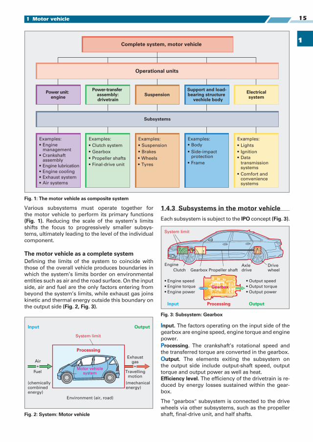
Steering wheelangle sensor
Hydraulic control unitwith integrated controller
Enginemanagement
2 pressure sensors ontandem master cylinder
Wheel speedsensor
Lateral accelerationsensor
ABS: Antilock Braking System+ ABV: Automatic regulation of braking-force distribution+ TCS: Traction Control System+ AYC: Active Yaw Control
= ESP: Electronic Stability Program
ABV
AYC
ABSESP
TCSESP
Yaw rate sensor
Subfunction: Active occupant protection, im-
provements in dynamic response
Operational unit: Electro-hydraulic systems
(open and closed-loop control
systems, such as ABS, ESP, etc.)
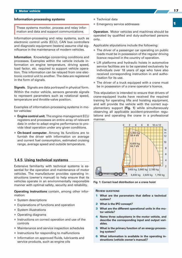
ECU forairbag
Driversideairbag
Seat belt
Crash sensor,driver side airbag
Seat with integratedside airbag
Subfunction: Passive protection for vehicle oc-
cupants
Operational unit: Electr., electron. systems (safe-
ty and security devices, such as
airbags, seatbelt tensioners)
1
151 Motor vehicle
Various subsystems must operate together for
the motor vehicle to perform its primary functions
(Fig. 1). Reducing the scale of the system’s limits
shifts the focus to progressively smaller subsys-
tems, ultimately leading to the level of the individual
component.
The motor vehicle as a complete systemDefining the limits of the system to coincide with
those of the overall vehicle produces boundaries in
which the system’s limits border on environmental
entities such as air and the road surface. On the input
side, air and fuel are the only factors entering from
beyond the system’s limits, while exhaust gas joins
kinetic and thermal energy outside this boundary on
the output side (Fig. 2, Fig. 3).
Operational units
Subsystems
Electricalsystem
Complete system, motor vehicle
Examples:
• Clutch system
• Final-drive unit
Examples::
• Suspension
Examples:
• Side-impactprotection
Examples::
• Lights
• Ignition
transmissionsystems
• Comfort andconveniencesystems
Examples:
• Enginemanagement
• Crankshaftassembly
• Engine lubrication
• Engine cooling
• Exhaust system
• Air systems
SuspensionSupport and load-bearing structure
vechicle body
Power-transferassembly:drivetrain
Power unit:engine
• Data
• Body
• Frame
• Brakes
• Wheels
• Tyres
• Gearbox
• Propeller shafts
Fig. 1: The motor vehicle as composite system
1.4.3 Subsystems in the motor vehicle
Each subsystem is subject to the IPO concept (Fig. 3).
Input. The factors operating on the input side of the
gearbox are engine speed, engine torque and engine
power.
Processing. The crankshaft’s rotational speed and
the transferred torque are converted in the gearbox.
Output. The elements exiting the subsystem on
the output side include output-shaft speed, output
torque and output power as well as heat.
Efficiency level. The efficiency of the drivetrain is re-
duced by energy losses sustained within the gear-
box.
The "gearbox" subsystem is connected to the drive
wheels via other subsystems, such as the propeller
shaft, final-drive unit, and half shafts.
Motor vehiclesystem Travelling
motion
Input Output
Air
+
Fuel
(chemicallycombinedenergy)
Environment (air, road)
System limit
Processing
Exhaustgas+
(mechanicalenergy)
Fig. 2: System: Motor vehicle
Input Output
Engine
Processing
Clutch GearboxAxle drive
Drive wheel
• Engine speed
• Engine torque
• Engine power
• Output speed
• Output torque
• Output power
System limit
Propeller shaft
Gearbox
Fig. 3: Subsystem: Gearbox

1
1 Motor vehicle16
1.4.4 Classifications of technical systems and subsystems by processing mode
Technical systems (Fig. 1) are classified according to
the type of processing within overall systems:
● Material-processing systems such as the fuel-sup-
ply system
● Energy-processing systems such as the internal-
combustion engine
● Information-processing systems such as the on-
board computer, the steering system, etc.
Material-processing systems
Transport media and basic machinery are employed
to convey substances and materials. Machine tools
assume responsibility for shaping materials. To cite
an example: in the material-transport process, a
pump induces motion in a static fluid (gasoline in the
fuel tank) in order to transport it to the fuel-injection
system. For this purpose, electrical energy must be
supplied to the operational machinery, such as a fuel
pump, that is responsible for the process.
Overview of material-processing systems:
Machines for reshaping include machine tools such
as drills, mills and lathes as well as the equipment
found in foundries and stamping plants such as met-
al presses.
Machines for repositioning include all convey-
ors, transporters and machines used to transport
solid materials (conveyor belts, fork lift trucks,
trucks, passenger cars), liquids (pumps) and gases
(fans, turbines).
Examples of material-processing systems within the
motor vehicle:
● Lubrication system, in which the oil pump pro-
vides the motive power for material propulsion.
● Cooling system, in which the water pump trans-
ports a medium to support thermal transfer.
Energy-processing systems
This class embraces all manner of power-generation
machines, including internal-combustion engines and
electric motors, steam engines and gas power plants,
as well as energy units such as heat pumps, photo-
voltaic systems and fuel cells. In the realm of energy
conversion the operative distinction is between:
● Heat engines, such as spark-ignition and diesel
engines, and gas turbines
● Hydraulically powered machines, such as water
turbines
● Wind-energy devices, such as wind-powered gen-
erators
● Solar-energy converters, such as photovoltaic
systems
● Fuel cells
Within the internal-combustion engine, the fuel's
chemical energy is initially converted into thermal
energy before undergoing a second transformation
to emerge as kinetic energy (Fig. 2).
This process can generate additional substances
and information. Since these are of secondary im-
portance in the operation of the energy-processing
machine, they are not usually primary objects of at-
tention.
The flow of substances and materials (entry of fuel
and emission of exhaust gases) and the flow of infor-
mation (fuel/air mixture, engine-speed control, steer-
ing, etc.) all assume the role of secondary functions.
Energy-processing system. The primary focus is on
converting chemical energy contained in fuel into ki-
netic energy to propel the vehicle, with the internal-combus tion engine serving as the energy-process-
ing system.
Informationprocessing
Energyprocessing
Materialprocessing
Fig. 1: Systems classified according to processing mode
Material-processing systems modify materials
in their geometrical configuration (reshape) or
transport them from one position to another (re-
position).
Energy-processing systems transform energy from
an external source from one form into another.
Chemicalenergy
Mechanicalenergy
Fuel/air mixture
Combustion
Torque atcrankshaft
Thermal energy
Conrod force
Fig. 2: Energy processing in the spark-ignition engine
1
171 Motor vehicle
Information-processing systems
Information-processing and relay systems, such as
electronic control units (ECU), CAN bus controllers
and diagnostic equipment (testers) assume vital sig-
nificance in the maintenance of modern vehicles.
Information. Knowledge concerning conditions and
processes. Examples within the vehicle include in-
formation on engine temperature, driving speed,
load factor, etc. required to support vehicle opera-
tion. This information can be relayed from one elec-
tronic control unit to another. The data are registered
in the form of signals.
Signals. Signals are data portrayed in physical form.
Within the motor vehicle, sensors generate signals
to represent parameters such as rotational speed,
temperature and throttle-valve position.
Examples of information-processing systems in mo-
tor vehicles:
● Engine control unit. The engine-management ECU
registers and processes an entire array of relevant
data in order to adapt engine performance to pro-
vide ideal operation under any given conditions.
● On-board computer. Among its functions are to
furnish the driver with information on average
and current fuel consumption, estimated cruising
range, average speed and outside temperature.
1.4.5 Using technical systems
Extensive familiarity with technical systems is es-
sential for the operation and maintenance of motor
vehicles. The manufacturer provides operating in-
structions (owner's manual) to help ensure that its
vehicles operate in an environmentally responsible
manner with optimal safety, security and reliability.
Operating instructions contain, among other infor-
mation:
● System descriptions
● Explanations of functions and operation
● System illustrations
● Operating diagrams
● Instructions on correct operation and use of the
controls
● Maintenance and service inspection schedules
● Instructions for responding to malfunctions
● Information on approved fluids, lubricants and
service products, such as engine oils
● Technical data
● Emergency service addresses
Operation. Motor vehicles and machines should be
operated by qualified and duly-authorised persons
only.
Applicable stipulations include the following:
● The driver of a passenger car operating on public
roads must be in possession of the regular driving
licence required in the country of operation.
● Lift platforms and hydraulic hoists in automotive
service facilities are to be operated exclusively by
individuals over 18 years of age who have also
received corresponding instruction in and autho-
risation for its use.
● The driver of a truck equipped with a crane must
be in possession of a crane operator's licence.
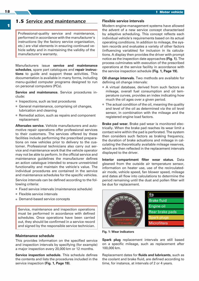
This stipulation is intended to ensure that drivers of
crane-equipped trucks have received the required
training for operating lifts and hoisting equipment,
and will provide the vehicle with the correct sup-
plementary support (Fig. 1) while simultaneously
observing all applicable accident-prevention regu-
lations and operating the crane in a professional
manner.
These systems monitor, process and relay infor-
mation and data and support communications.
14m
0 2 4 6 8 10 12m
12
10
8
6
4
2
2,180 kg7,400 kg 3,860 kg
1,750 kg2,820 kg5,830 kg
5,950 kg58.4 kN
6,600 kg64.7 kN
Fig. 1: Correct load distribution on a crane hoist
REVIEW QUESTIONS
1 What are the parameters that define a technical system?
2 What is the IPO concept?
3 What are the different operational units in the mo-tor vehicle?
4 Name three subsystems in the motor vehicle, and describe the corresponding input and output vari-ables.
5 What is the primary function of an energy-process-ing system?
6 What information is available in the operating in-structions (vehicle owner's manual)?
1
1 Motor vehicle18
1.5 Service and maintenance
Manufacturers issue service and maintenance schedules, spare part catalogues and repair instruc-tions to guide and support these activities. This
documentation is available in many forms, including
menu-guided computer programs designed to run
on personal computers (PCs).
Service and maintenance. Service procedures in-
clude:
● Inspections, such as test procedures
● General maintenance, comprising oil changes,
lubrication and cleaning
● Remedial action, such as repairs and component
replacement
Aftersales service. Vehicle manufacturers and auto-
motive repair operations offer professional services
to their customers. The services offered by these
facilities include performing the prescribed prepara-
tions on new vehicles prior to delivery to the cus-
tomer. Professional technicians also carry out ser-
vice and maintenance work that the vehicle operator
may not be able to perform. In the official service and
maintenance guidelines the manufacturer defines
an action catalogue intended to ensure unrestricted
functionality and maintain the vehicle's value. The
individual procedures are contained in the service
and maintenance schedules for the specific vehicles.
Service intervals can be defined according to the fol-
lowing criteria:
● Fixed service intervals (maintenance schedule)
● Flexible service intervals
� Demand-based service concepts
Maintenance scheduleThis provides information on the specified service
and inspection intervals by specifying (for example)
a major inspection every 20,000 km or 12 months.
Service inspection schedule. This schedule defines
the contents and lists the procedures included in the
service inspection (Fig. 1, Page 19).
Flexible service intervalsModern engine-management systems have allowed
the advent of a new service concept characterised
by adaptive scheduling. This concept reflects each
individual vehicle's requirements based on its actual
operating conditions. In addition to mileage, the sys-
tem records and evaluates a variety of other factors
(influencing variables) for inclusion in its calcula-
tions. A display then provides the driver with prompt
notice as the inspection date approaches (Fig. 1). The
process culminates with execution of the prescribed
operations at the service facility in accordance with
the service inspection schedule (Fig. 1, Page 19).
Oil change intervals. Two methods are available for
defining oil change intervals:
● A virtual database, derived from such factors as
mileage, overall fuel consumption and oil tem-
perature curves, provides an index indicating how
much the oil ages over a given period.
● The actual condition of the oil, meaning the quality
and level of the oil as determined via the oil level
sensor, in combination with the mileage and the
registered engine load factors.
Brake pad wear. Brake pad wear is monitored elec-
trically. When the brake pad reaches its wear limit a
contact wire within the pad is perforated. The system
then considers such factors as braking frequency,
the duration of brake actuations and mileage in cal-
culating the theoretically available mileage reserves,
which are then reflected in the replacement intervals
displayed to the driver.
Interior compartment filter wear status. Data
gleaned from the outside air temperature sensor,
information on heater use, use of the recirculated-
air mode, vehicle speed, fan blower speed, mileage
and dates all flow into calculations to determine the
period remaining until the dust and pollen filter will
be due for replacement.
Spark plug replacement intervals are still based
on a specific mileage, such as replacement after
100,000 km.
Replacement dates for fluids and lubricants, such as
the coolant and brake fluid, are defined according to
time, for instance, at intervals of 2 or 4 years.
Professional-quality service and maintenance,
performed in accordance with the manufacturer's
instructions (by the factory service organisation,
etc.) are vital elements in ensuring continued ve-
hicle safety and in maintaining the validity of the
manufacturer's warranty.
Service, maintenance and inspection operations
must be performed in accordance with defined
schedules. Once operations have been carried
out, they should be confirmed in a service record
and signed by the responsible service technician.
Brake fluid
Engine oil
Rear brake pads
Spark plugs
Microfilters12 months
Fig. 1: Wear indicators
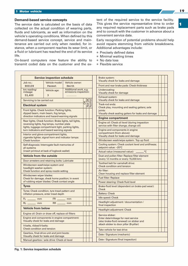
1
191 Motor vehicle
Demand-based service conceptsThe service date is calculated on the basis of data
collected on the actual condition of wearing parts,
fluids and lubricants, as well as information on the
vehicle's operating conditions. When defined by this
demand-based service concept, service and main-
tenance are carried out only when needed, for in-
stance, when a component reaches its wear limit, or
a fluid or lubricant has reached the end of its service
life.
On-board computers now feature the ability to
transmit coded data on the customer and the ex-
tent of the required service to the service facility.
This gives the service representative time to order
any required replacement parts such as brake pads
and to consult with the customer in advance about a
convenient service date.
Early recognition of potential problems should help
avoid repairs stemming from vehicle breakdowns.
Additional advantages include:
● Precisely defined dates
● Minimal waiting times
● No data loss
● Flexible service
Fig. 1: Service inspection schedule
FL mm
Service inspection schedule
Job no.: Vehicle model: Vehicle owner:
km reading/mileage:
Vehicle age: Additional work, e.g.emissions inspection:
…………
Servicing to be carried out
OK
No
t O
K
Rec
tifi
ed
Electrical system
Vehicle from the outside
Tyres
Vehicle from below
Engine compartment
Front lights. Check function: Parking lights,
dipped beam, main beam, fog lamps,
direction indicators and hazard-warning signals
Rear lights. Check function: Brake lights, tail lights,
reversing lights, fog lamps, number plate
lights, luggage compartment light, parking lights,
turn indicators and hazard warning signals
Interior and glove-compartment lights,
cigarette lighter, signal horn and indicator lamps:
Check function
Self-diagnosis: Interrogate fault memories of
all systems
(insert printout at back of logbook wallet)
Door arresters and retaining bolts: Lubricate
Windscreen wash/wipe system and
headlight washer system:
Check function and spray-nozzle setting
Windscreen wiper blades:
Check for damage, check home position; in event
of rubbing wiper blades: Check contact angle
Tyres: Check condition, tyre tread pattern and
inflation pressure, enter tread depth
FR mm
RL mm RR mm
Engine oil: Drain or draw off, replace oil filters
V-belts, ribbed V-belts:
Check condition and tension
Gearbox, final-drive unit and joint boots:
Visually check for leaks and damage
Manual gearbox / axle drive: Check oil level
Brake system:
Visually check for leaks and damage
Front and rear brake pads: Check thickness
Undercoating:
Visually check for damage
Exhaust system:
Visually check for leaks and damage
Track-rod ends:
Check play, mounting and sealing gaiters; axle
joints:
Visually check sealing gaiters for leaks and damage
Engine oil: Check oil level (during inspection
service with filter change, change oil)
Engine and components in engine
compartment (from above):
Visually check for leaks and damage
Windscreen wash/wipe system: Top up fluid
Cooling system: Check coolant level and antifreeze;
setpoint value: –25°C
Actual value (measured value): °C
Dust and pollen filter: Replace filter element
(every 12 months or every 15,000 km)
Toothed belt for camshaft drive:
Check condition and tension
Air filter:
Clean housing and replace filter element
Fuel filter: Replace
Power steering: Check fluid level
Brake-fluid level (dependent on brake-pad wear):
Check
Battery: Check
Idle speed: Check
Headlight adjustment / documentation /
final inspection
Headlight adjustment: Check
Service sticker:
Enter date/mileage for next service
(also brake-fluid renewal) on sticker and
attach sticker to door pillar (B-pillar)
Take vehicle for test drive
Date / Signature (mechanic)
Date / Signature (final inspection)
Engine and components in engine compartment:
Visually check for leaks and damage
,
SmithPassat
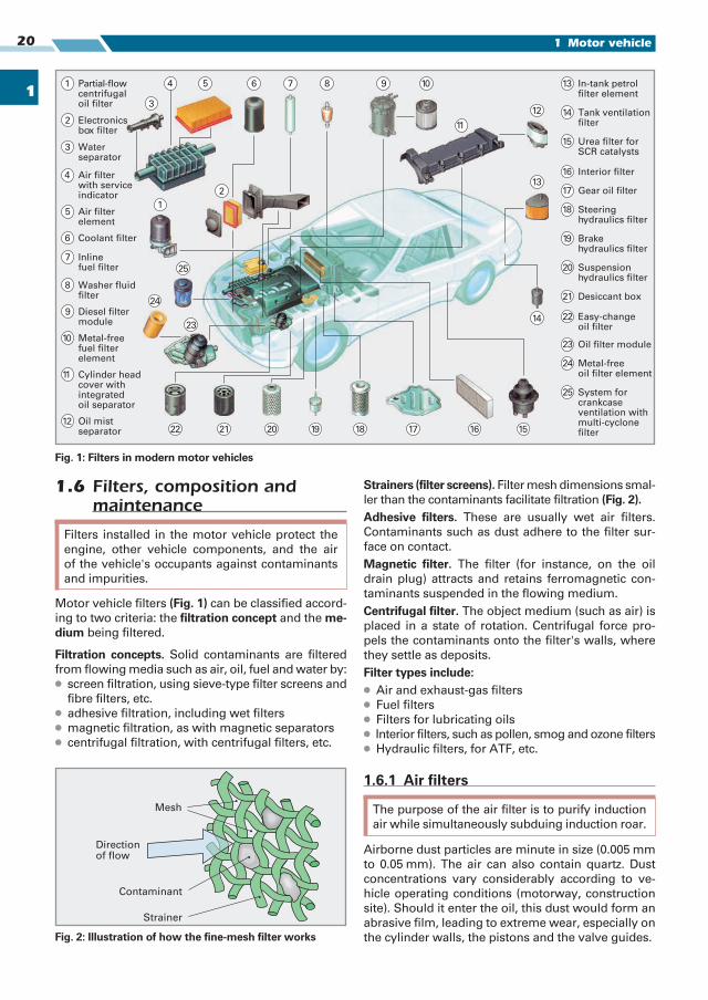
1
1 Motor vehicle20
1.6 Filters, composition and maintenance
Motor vehicle filters (Fig. 1) can be classified accord-
ing to two criteria: the filtration concept and the me-dium being filtered.
Filtration concepts. Solid contaminants are filtered
from flowing media such as air, oil, fuel and water by:
● screen filtration, using sieve-type filter screens and
fibre filters, etc.
● adhesive filtration, including wet filters
● magnetic filtration, as with magnetic separators
● centrifugal filtration, with centrifugal filters, etc.
Strainers (filter screens). Filter mesh dimensions smal-
ler than the contaminants facilitate filtration (Fig. 2).Adhesive filters. These are usually wet air filters.
Contaminants such as dust adhere to the filter sur-
face on contact.
Magnetic filter. The filter (for instance, on the oil
drain plug) attracts and retains ferromagnetic con-
taminants suspended in the flowing medium.
Centrifugal filter. The object medium (such as air) is
placed in a state of rotation. Centrifugal force pro-
pels the contaminants onto the filter's walls, where
they settle as deposits.
Filter types include:● Air and exhaust-gas filters
● Fuel filters
● Filters for lubricating oils
● Interior filters, such as pollen, smog and ozone filters
● Hydraulic filters, for ATF, etc.
1.6.1 Air filters
Airborne dust particles are minute in size (0.005 mm
to 0.05 mm). The air can also contain quartz. Dust
concentrations vary considerably according to ve-
hicle operating conditions (motorway, construction
site). Should it enter the oil, this dust would form an
abrasive film, leading to extreme wear, especially on
the cylinder walls, the pistons and the valve guides.
Filters installed in the motor vehicle protect the
engine, other vehicle components, and the air
of the vehicle's occupants against contaminants
and impurities.
The purpose of the air filter is to purify induction
air while simultaneously subduing induction roar.
Strainer
Mesh
Directionof flow
Contaminant
Fig. 2: Illustration of how the fine-mesh filter works
Cylinder headcover withintegratedoil separator
Oil mistseparator
Air filterwith serviceindicator
Waterseparator
Air filterelement
Coolant filter
Inlinefuel filter
Washer fluidfilter
Diesel filtermodule
Metal-freefuel filterelement
In-tank petrolfilter element
Tank ventilationfilter
Urea filter forSCR catalysts
Interior filter
Gear oil filter
Steeringhydraulics filter
Brakehydraulics filter
Suspensionhydraulics filter
Desiccant box
Easy-changeoil filter
Oil filter module
Metal-freeoil filter element
System forcrankcaseventilation withmulti-cyclonefilter
Partial-flowcentrifugaloil filter
Electronicsbox filter
5
4
3
2
1
6
7
8
9
10
11
12
13
14
15
16
17
18
19
20
21
22
23
24
25
13
14
1516171819202122
23
24
25
54
3
2
1
6 7 8 9 10
11
12
Fig. 1: Filters in modern motor vehicles