Embed Size (px)
Citation preview
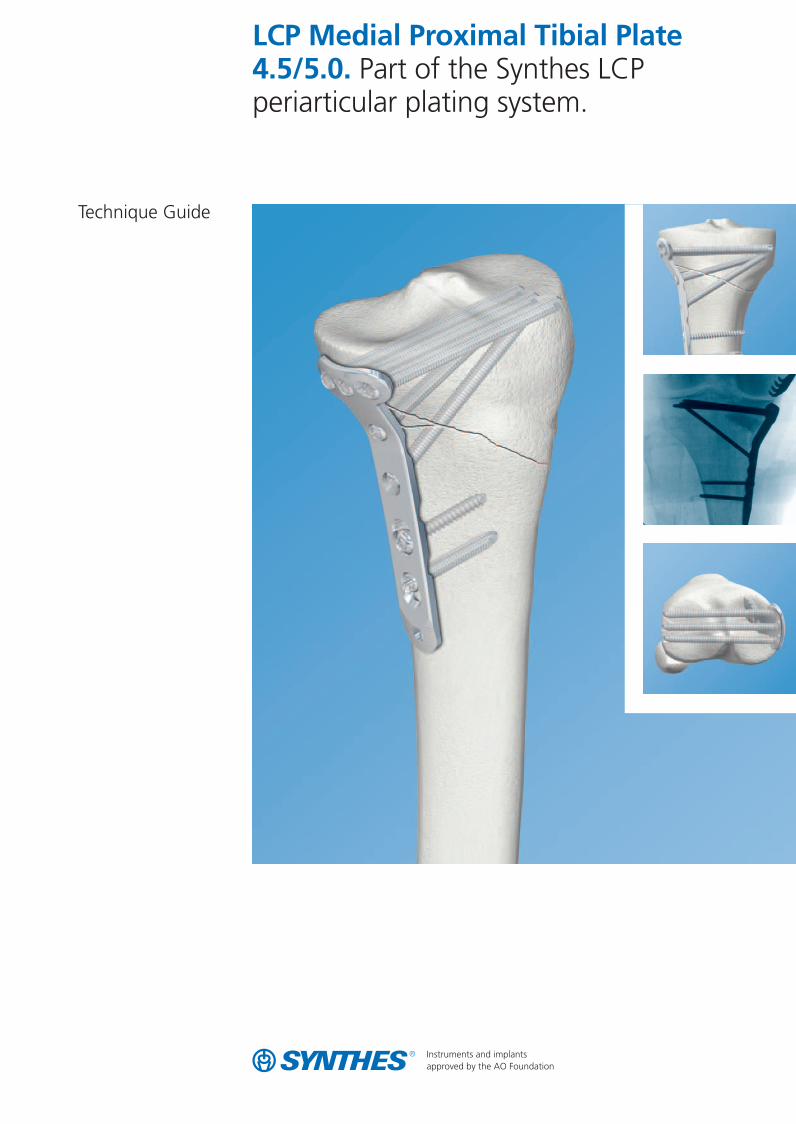
LCP Medial Proximal Tibial Plate4.5/5.0. Part of the Synthes LCPperiarticular plating system.
Technique Guide
0X6.000.360_AB.qxp:0X6.000.360_AB 04.12.2008 15:05 Uhr Seite Cvr1

0X6.000.360_AB.qxp:0X6.000.360_AB 04.12.2008 15:05 Uhr Seite Cvr2
Introduction
Surgical Technique 6
Product Information
LCP Medial Proximal Tibial Plate 4.5/5.0 2
AO Principles 4
Indications 5
Instruments for Minimally Invasive Osteosynthesis 23
Plates 24
Screws 25
Drill and Wire Guides 27
Sets 28
Image intensifier control
WarningThis description is not sufficient for immediate application ofthe instrumentation. Instruction by a surgeon experienced inhandling this instrumentation is highly recommended.
Table of Contents
Synthes 1
0X6.000.360_AB.qxp:0X6.000.360_AB 04.12.2008 15:05 Uhr Seite 1
LCP Medial Proximal Tibial Plate4.5/5.0. Part of the Synthes LCPperiarticular plating system.
2 Synthes LCP Medial Proximal Tibial Plate 4.5/5.0 Technique Guide
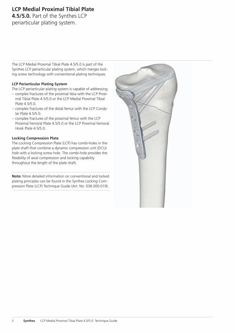
The LCP Medial Proximal Tibial Plate 4.5/5.0 is part of theSynthes LCP periarticular plating system, which merges lock-ing screw technology with conventional plating techniques.
LCP Periarticular Plating SystemThe LCP periarticular plating system is capable of addressing:– complex fractures of the proximal tibia with the LCP Proxi-
mal Tibial Plate 4.5/5.0 or the LCP Medial Proximal TibialPlate 4.5/5.0.
– complex fractures of the distal femur with the LCP Condy-lar Plate 4.5/5.0.
– complex fractures of the proximal femur with the LCPProximal Femoral Plate 4.5/5.0 or the LCP Proximal FemoralHook Plate 4.5/5.0.
Locking Compression PlateThe Locking Compression Plate (LCP) has combi-holes in theplate shaft that combine a dynamic compression unit (DCU)hole with a locking screw hole. The combi-hole provides theflexibility of axial compression and locking capabilitythroughout the length of the plate shaft.
Note: More detailed information on conventional and lockedplating principles can be found in the Synthes Locking Com-pression Plate (LCP) Technique Guide (Art. No. 036.000.019).
0X6.000.360_AB.qxp:0X6.000.360_AB 04.12.2008 15:05 Uhr Seite 2
Synthes 3
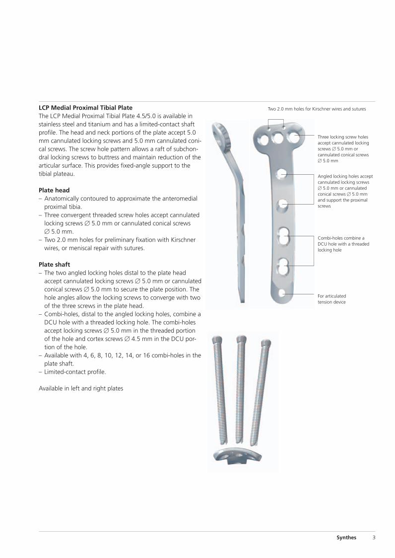
LCP Medial Proximal Tibial PlateThe LCP Medial Proximal Tibial Plate 4.5/5.0 is available instainless steel and titanium and has a limited-contact shaftprofile. The head and neck portions of the plate accept 5.0mm cannulated locking screws and 5.0 mm cannulated coni-cal screws. The screw hole pattern allows a raft of subchon-dral locking screws to buttress and maintain reduction of thearticular surface. This provides fixed-angle support to the tibial plateau.
Plate head– Anatomically contoured to approximate the anteromedial
proximal tibia. – Three convergent threaded screw holes accept cannulated
locking screws � 5.0 mm or cannulated conical screws� 5.0 mm.
– Two 2.0 mm holes for preliminary fixation with Kirschnerwires, or meniscal repair with sutures.
Plate shaft– The two angled locking holes distal to the plate head
accept cannulated locking screws � 5.0 mm or cannulatedconical screws � 5.0 mm to secure the plate position. Thehole angles allow the locking screws to converge with twoof the three screws in the plate head.
– Combi-holes, distal to the angled locking holes, combine aDCU hole with a threaded locking hole. The combi-holesaccept locking screws � 5.0 mm in the threaded portionof the hole and cortex screws � 4.5 mm in the DCU por-tion of the hole.
– Available with 4, 6, 8, 10, 12, 14, or 16 combi-holes in theplate shaft.
– Limited-contact profile.
Available in left and right plates
Two 2.0 mm holes for Kirschner wires and sutures
Three locking screw holesaccept cannulated lockingscrews � 5.0 mm orcannulated conical screws� 5.0 mm
Angled locking holes acceptcannulated locking screws� 5.0 mm or cannulatedconical screws � 5.0 mmand support the proximalscrews
Combi-holes combine a DCU hole with a threaded locking hole
For articulated tension device
0X6.000.360_AB.qxp:0X6.000.360_AB 04.12.2008 15:05 Uhr Seite 3
AO Principles
4 Synthes LCP Medial Proximal Tibial Plate 4.5/5.0 Technique Guide
In 1958, the AO formulated four basic principles which havebecome the guidelines for internal fixation.1 Those principles,as applied to the LCP Medial Proximal Tibial Plate 4.5/5.0,are:
Anatomic reductionFacilitates restoration of the articular surface by exact screwplacement using guide wires for reduction and insertion ofcannulated screws.
Stable fixationLocking screws create a fixed-angle construct, providing angular stability.
Preservation of blood supplyTapered end simplifies submuscular plate insertion. Limited-contact shaft profile reduces plate-to-bone contact and vas-cular trauma.
Early, active mobilizationPlate features combined with AO technique create an envi-ronment for bone healing, expediting a return to optimalfunction.
1 M.E. Müller, M. Allgöwer, R. Schneider, and H. Willenegger (1991) AO Manual ofInternal Fixation, 3rd Edition. Berlin: Springer.
0X6.000.360_AB.qxp:0X6.000.360_AB 04.12.2008 15:05 Uhr Seite 4
Indications
Synthes 5
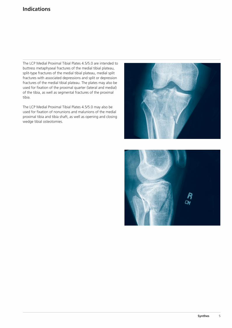
The LCP Medial Proximal Tibial Plates 4.5/5.0 are intended tobuttress metaphyseal fractures of the medial tibial plateau,split-type fractures of the medial tibial plateau, medial splitfractures with associated depressions and split or depressionfractures of the medial tibial plateau. The plates may also beused for fixation of the proximal quarter (lateral and medial)of the tibia, as well as segmental fractures of the proximaltibia.
The LCP Medial Proximal Tibial Plates 4.5/5.0 may also beused for fixation of nonunions and malunions of the medialproximal tibia and tibia shaft, as well as opening and closingwedge tibial osteotomies.
0X6.000.360_AB.qxp:0X6.000.360_AB 04.12.2008 15:05 Uhr Seite 5
1.
60
1.
6 Synthes LCP Medial Proximal Tibial Plate 4.5/5.0 Technique Guide
Surgical Technique
1Preparation and preoperative planning
Required sets
Plate Set LCP Medial Proximal Tibial Plates 4.5/5.0
Periarticular LCP Plating System Instrument Set
Cannulated Conical and Cannulated Locking Screw Set� 5.0 and 7.3 mm
LCP Large Fragment Instrument Set
LCP Large Fragment Screw Set
Complete the preoperative radiographic assessment and prepare the preoperative plan. Determine plate length andinstruments to be used.
Important: Determine proximal screw placement and screwlengths to ensure proper screw placement in the metaphysis.
Position the patient supine on a radiolucent operating table.Visualization of the proximal tibia under fluoroscopy in boththe lateral and AP views is necessary.
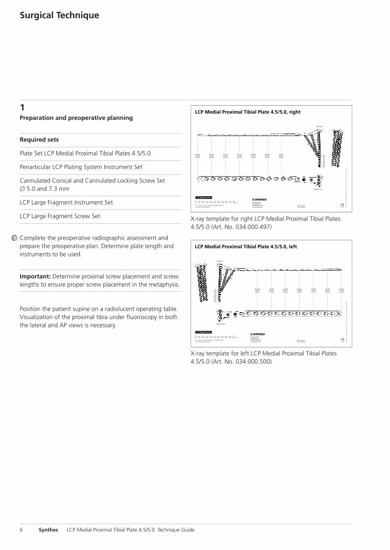
X-ray template for right LCP Medial Proximal Tibial Plates4.5/5.0 (Art. No. 034.000.497)
X-ray template for left LCP Medial Proximal Tibial Plates4.5/5.0 (Art. No. 034.000.500)
0X6.000.360_AB.qxp:0X6.000.360_AB 04.12.2008 15:05 Uhr Seite 6
Synthes 7
2Reduce articular surface
Optional instruments
117.700 Instrument Set for Large Distractor inSterilization Tray
01.301.000 Large External Fixator in Vario Case
394.350 Large Distractor
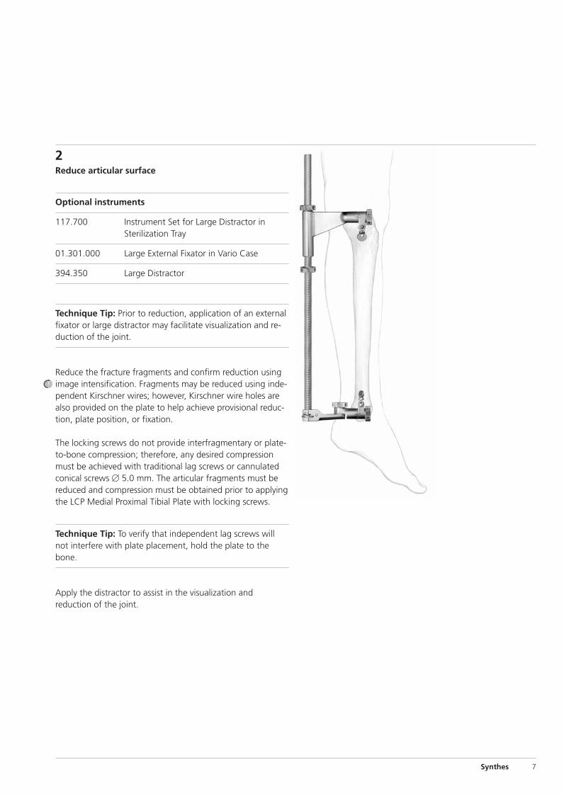
Technique Tip: Prior to reduction, application of an externalfixator or large distractor may facilitate visualization and re-duction of the joint.
Reduce the fracture fragments and confirm reduction usingimage intensification. Fragments may be reduced using inde-pendent Kirschner wires; however, Kirschner wire holes arealso provided on the plate to help achieve provisional reduc-tion, plate position, or fixation.
The locking screws do not provide interfragmentary or plate-to-bone compression; therefore, any desired compressionmust be achieved with traditional lag screws or cannulatedconical screws � 5.0 mm. The articular fragments must bereduced and compression must be obtained prior to applyingthe LCP Medial Proximal Tibial Plate with locking screws.
Technique Tip: To verify that independent lag screws willnot interfere with plate placement, hold the plate to thebone.
Apply the distractor to assist in the visualization and reduction of the joint.
0X6.000.360_AB.qxp:0X6.000.360_AB 04.12.2008 15:05 Uhr Seite 7
8 Synthes LCP Medial Proximal Tibial Plate 4.5/5.0 Technique Guide
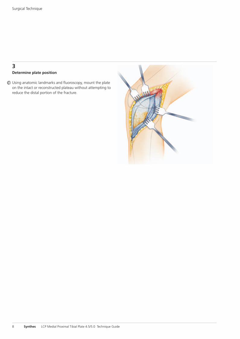
3Determine plate position
Using anatomic landmarks and fluoroscopy, mount the plateon the intact or reconstructed plateau without attempting toreduce the distal portion of the fracture.
Surgical Technique
0X6.000.360_AB.qxp:0X6.000.360_AB 04.12.2008 15:05 Uhr Seite 8
Synthes 9
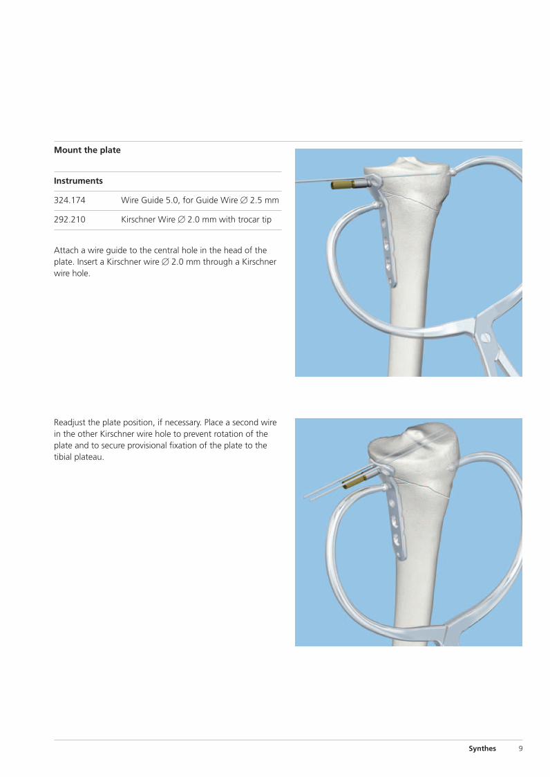
Mount the plate
Instruments
324.174 Wire Guide 5.0, for Guide Wire � 2.5 mm
292.210 Kirschner Wire � 2.0 mm with trocar tip
Attach a wire guide to the central hole in the head of theplate. Insert a Kirschner wire � 2.0 mm through a Kirschnerwire hole.
Readjust the plate position, if necessary. Place a second wirein the other Kirschner wire hole to prevent rotation of theplate and to secure provisional fixation of the plate to thetibial plateau.
0X6.000.360_AB.qxp:0X6.000.360_AB 04.12.2008 15:05 Uhr Seite 9
10 Synthes LCP Medial Proximal Tibial Plate 4.5/5.0 Technique Guide
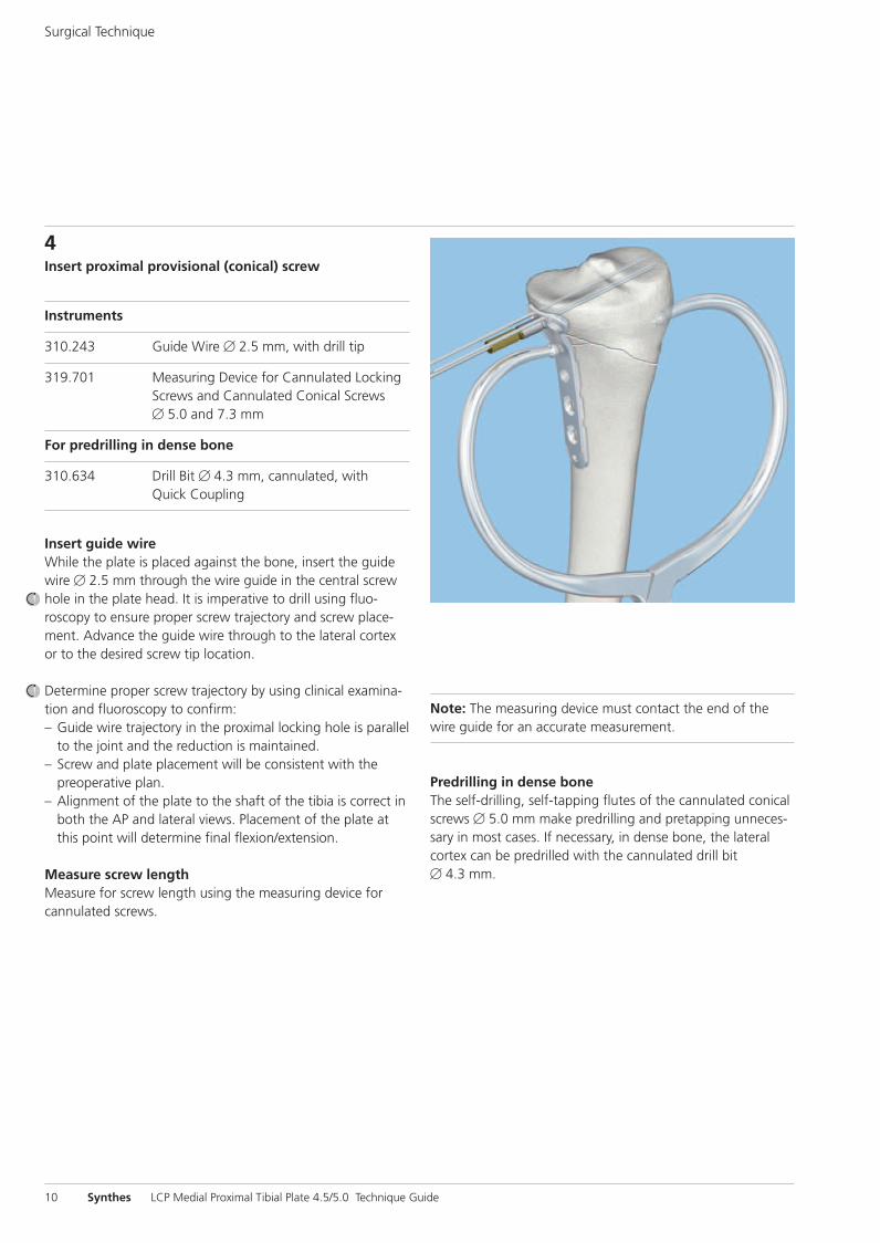
4Insert proximal provisional (conical) screw
Instruments
310.243 Guide Wire � 2.5 mm, with drill tip
319.701 Measuring Device for Cannulated LockingScrews and Cannulated Conical Screws� 5.0 and 7.3 mm
For predrilling in dense bone
310.634 Drill Bit � 4.3 mm, cannulated, withQuick Coupling
Insert guide wireWhile the plate is placed against the bone, insert the guidewire � 2.5 mm through the wire guide in the central screwhole in the plate head. It is imperative to drill using fluo-roscopy to ensure proper screw trajectory and screw place-ment. Advance the guide wire through to the lateral cortexor to the desired screw tip location.
Determine proper screw trajectory by using clinical examina-tion and fluoroscopy to confirm:– Guide wire trajectory in the proximal locking hole is parallel
to the joint and the reduction is maintained.– Screw and plate placement will be consistent with the
preoperative plan.– Alignment of the plate to the shaft of the tibia is correct in
both the AP and lateral views. Placement of the plate atthis point will determine final flexion/extension.
Measure screw lengthMeasure for screw length using the measuring device forcannulated screws.
Surgical Technique
Note: The measuring device must contact the end of thewire guide for an accurate measurement.
Predrilling in dense boneThe self-drilling, self-tapping flutes of the cannulated conicalscrews � 5.0 mm make predrilling and pretapping unneces-sary in most cases. If necessary, in dense bone, the lateralcortex can be predrilled with the cannulated drill bit � 4.3 mm.
0X6.000.360_AB.qxp:0X6.000.360_AB 04.12.2008 15:05 Uhr Seite 10
Synthes 11
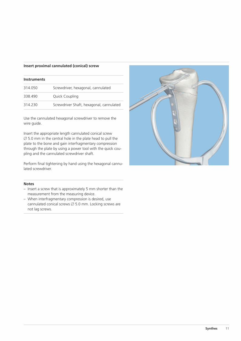
Insert proximal cannulated (conical) screw
Instruments
314.050 Screwdriver, hexagonal, cannulated
338.490 Quick Coupling
314.230 Screwdriver Shaft, hexagonal, cannulated
Use the cannulated hexagonal screwdriver to remove thewire guide.
Insert the appropriate length cannulated conical screw � 5.0 mm in the central hole in the plate head to pull theplate to the bone and gain interfragmentary compressionthrough the plate by using a power tool with the quick cou-pling and the cannulated screwdriver shaft.
Perform final tightening by hand using the hexagonal cannu-lated screwdriver.
Notes– Insert a screw that is approximately 5 mm shorter than the
measurement from the measuring device. – When interfragmentary compression is desired, use
cannulated conical screws � 5.0 mm. Locking screws arenot lag screws.
0X6.000.360_AB.qxp:0X6.000.360_AB 04.12.2008 15:05 Uhr Seite 11
12 Synthes LCP Medial Proximal Tibial Plate 4.5/5.0 Technique Guide
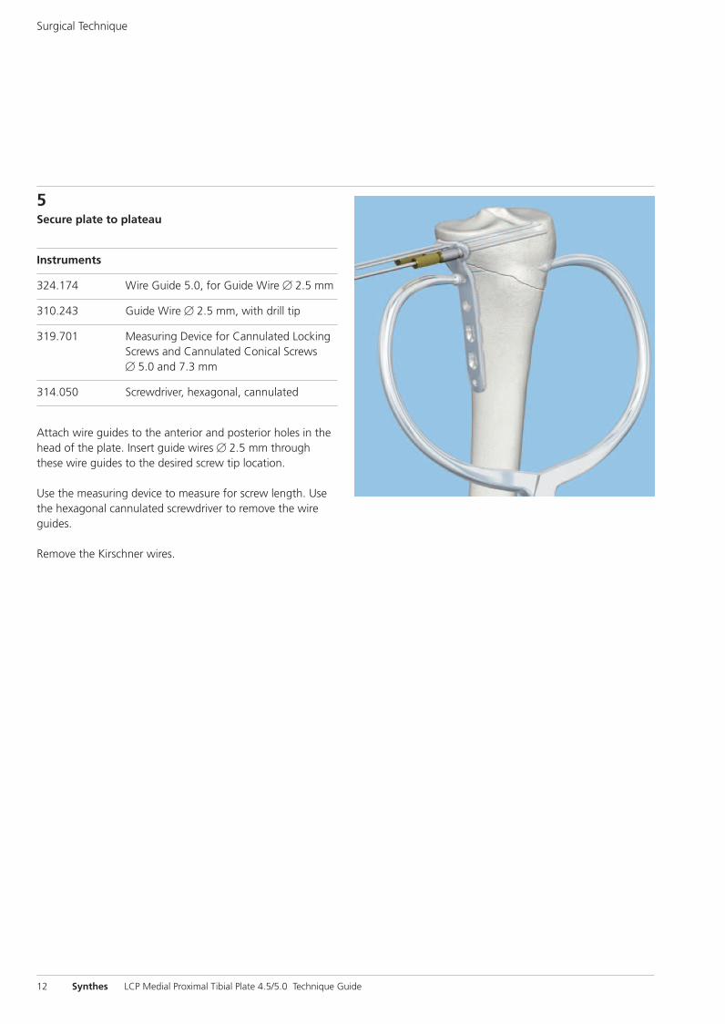
5Secure plate to plateau
Instruments
324.174 Wire Guide 5.0, for Guide Wire � 2.5 mm
310.243 Guide Wire � 2.5 mm, with drill tip
319.701 Measuring Device for Cannulated LockingScrews and Cannulated Conical Screws� 5.0 and 7.3 mm
314.050 Screwdriver, hexagonal, cannulated
Attach wire guides to the anterior and posterior holes in thehead of the plate. Insert guide wires � 2.5 mm throughthese wire guides to the desired screw tip location.
Use the measuring device to measure for screw length. Usethe hexagonal cannulated screwdriver to remove the wireguides.
Remove the Kirschner wires.
Surgical Technique
0X6.000.360_AB.qxp:0X6.000.360_AB 04.12.2008 15:05 Uhr Seite 12
Synthes 13
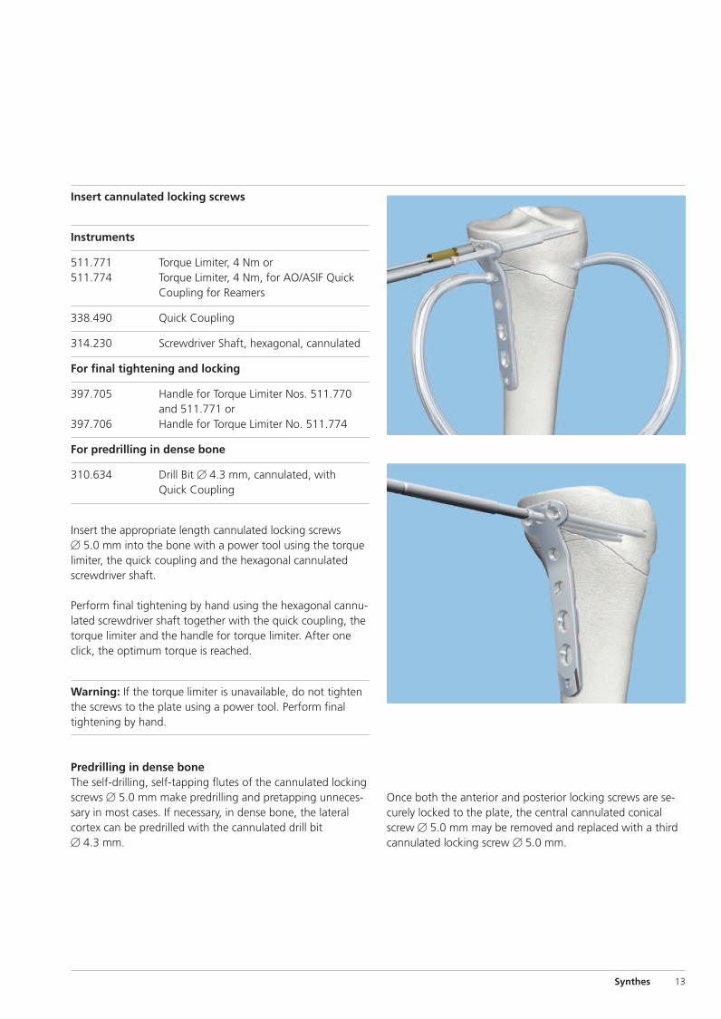
Insert cannulated locking screws
Instruments
511.771 Torque Limiter, 4 Nm or511.774 Torque Limiter, 4 Nm, for AO/ASIF Quick
Coupling for Reamers
338.490 Quick Coupling
314.230 Screwdriver Shaft, hexagonal, cannulated
For final tightening and locking
397.705 Handle for Torque Limiter Nos. 511.770and 511.771 or
397.706 Handle for Torque Limiter No. 511.774
For predrilling in dense bone
310.634 Drill Bit � 4.3 mm, cannulated, withQuick Coupling
Insert the appropriate length cannulated locking screws � 5.0 mm into the bone with a power tool using the torquelimiter, the quick coupling and the hexagonal cannulatedscrewdriver shaft.
Perform final tightening by hand using the hexagonal cannu-lated screwdriver shaft together with the quick coupling, thetorque limiter and the handle for torque limiter. After oneclick, the optimum torque is reached.
Warning: If the torque limiter is unavailable, do not tightenthe screws to the plate using a power tool. Perform finaltightening by hand.
Predrilling in dense boneThe self-drilling, self-tapping flutes of the cannulated lockingscrews � 5.0 mm make predrilling and pretapping unneces-sary in most cases. If necessary, in dense bone, the lateralcortex can be predrilled with the cannulated drill bit � 4.3 mm.
Once both the anterior and posterior locking screws are se-curely locked to the plate, the central cannulated conicalscrew � 5.0 mm may be removed and replaced with a thirdcannulated locking screw � 5.0 mm.
0X6.000.360_AB.qxp:0X6.000.360_AB 04.12.2008 15:05 Uhr Seite 13
Surgical Technique
14 Synthes LCP Medial Proximal Tibial Plate 4.5/5.0 Technique Guide
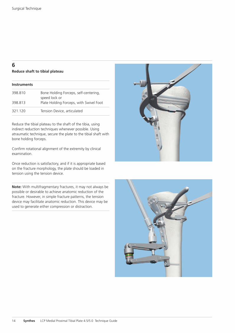
6Reduce shaft to tibial plateau
Instruments
398.810 Bone Holding Forceps, self-centering,speed lock or
398.813 Plate Holding Forceps, with Swivel Foot
321.120 Tension Device, articulated
Reduce the tibial plateau to the shaft of the tibia, using indirect reduction techniques whenever possible. Usingatraumatic technique, secure the plate to the tibial shaft withbone holding forceps.
Confirm rotational alignment of the extremity by clinical examination.
Once reduction is satisfactory, and if it is appropriate basedon the fracture morphology, the plate should be loaded intension using the tension device.
Note: With multifragmentary fractures, it may not always bepossible or desirable to achieve anatomic reduction of thefracture. However, in simple fracture patterns, the tensiondevice may facilitate anatomic reduction. This device may beused to generate either compression or distraction.
0X6.000.360_AB.qxp:0X6.000.360_AB 04.12.2008 15:05 Uhr Seite 14
1 2 2 1
2 1 1 2
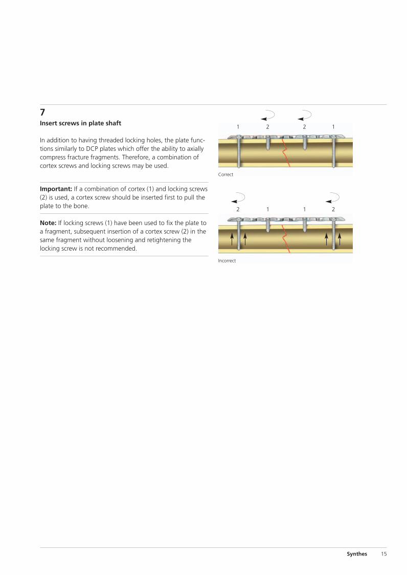
Correct
Incorrect
Synthes 15
7Insert screws in plate shaft
In addition to having threaded locking holes, the plate func-tions similarly to DCP plates which offer the ability to axiallycompress fracture fragments. Therefore, a combination ofcortex screws and locking screws may be used.
Important: If a combination of cortex (1) and locking screws(2) is used, a cortex screw should be inserted first to pull theplate to the bone.
Note: If locking screws (1) have been used to fix the plate toa fragment, subsequent insertion of a cortex screw (2) in thesame fragment without loosening and retightening thelocking screw is not recommended.
0X6.000.360_AB.qxp:0X6.000.360_AB 04.12.2008 15:05 Uhr Seite 15
16 Synthes LCP Medial Proximal Tibial Plate 4.5/5.0 Technique Guide
Surgical Technique
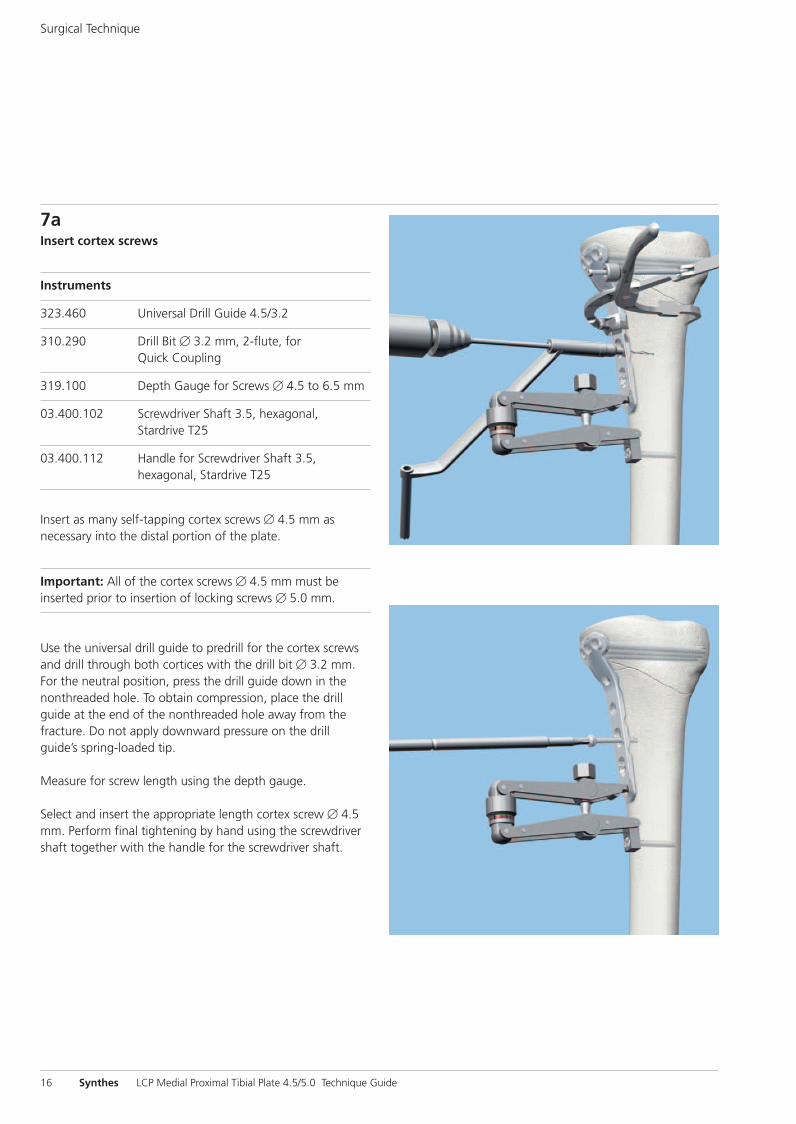
7aInsert cortex screws
Instruments
323.460 Universal Drill Guide 4.5/3.2
310.290 Drill Bit � 3.2 mm, 2-flute, forQuick Coupling
319.100 Depth Gauge for Screws � 4.5 to 6.5 mm
03.400.102 Screwdriver Shaft 3.5, hexagonal,Stardrive T25
03.400.112 Handle for Screwdriver Shaft 3.5,hexagonal, Stardrive T25
Insert as many self-tapping cortex screws � 4.5 mm as necessary into the distal portion of the plate.
Important: All of the cortex screws � 4.5 mm must be inserted prior to insertion of locking screws � 5.0 mm.
Use the universal drill guide to predrill for the cortex screwsand drill through both cortices with the drill bit � 3.2 mm.For the neutral position, press the drill guide down in thenonthreaded hole. To obtain compression, place the drillguide at the end of the nonthreaded hole away from thefracture. Do not apply downward pressure on the drillguide’s spring-loaded tip.
Measure for screw length using the depth gauge.
Select and insert the appropriate length cortex screw � 4.5mm. Perform final tightening by hand using the screwdrivershaft together with the handle for the screwdriver shaft.
0X6.000.360_AB.qxp:0X6.000.360_AB 04.12.2008 15:05 Uhr Seite 16
Synthes 17
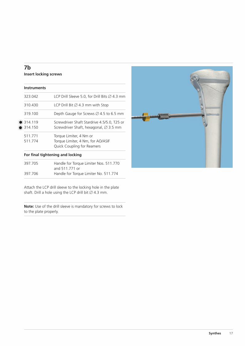
7bInsert locking screws
Instruments
323.042 LCP Drill Sleeve 5.0, for Drill Bits � 4.3 mm
310.430 LCP Drill Bit � 4.3 mm with Stop
319.100 Depth Gauge for Screws � 4.5 to 6.5 mm
314.119 Screwdriver Shaft Stardrive 4.5/5.0, T25 or314.150 Screwdriver Shaft, hexagonal, � 3.5 mm
511.771 Torque Limiter, 4 Nm or511.774 Torque Limiter, 4 Nm, for AO/ASIF
Quick Coupling for Reamers
For final tightening and locking
397.705 Handle for Torque Limiter Nos. 511.770and 511.771 or
397.706 Handle for Torque Limiter No. 511.774
Attach the LCP drill sleeve to the locking hole in the plateshaft. Drill a hole using the LCP drill bit � 4.3 mm.
Note: Use of the drill sleeve is mandatory for screws to lockto the plate properly.
0X6.000.360_AB.qxp:0X6.000.360_AB 04.12.2008 15:05 Uhr Seite 17
18 Synthes LCP Medial Proximal Tibial Plate 4.5/5.0 Technique Guide
Surgical Technique
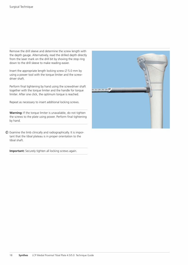
Remove the drill sleeve and determine the screw length withthe depth gauge. Alternatively, read the drilled depth directlyfrom the laser mark on the drill bit by shoving the stop ringdown to the drill sleeve to make reading easier.
Insert the appropriate length locking screw � 5.0 mm by using a power tool with the torque limiter and the screw-driver shaft.
Perform final tightening by hand using the screwdriver shafttogether with the torque limiter and the handle for torquelimiter. After one click, the optimum torque is reached.
Repeat as necessary to insert additional locking screws.
Warning: If the torque limiter is unavailable, do not tightenthe screws to the plate using power. Perform final tighteningby hand.
Examine the limb clinically and radiographically. It is impor-tant that the tibial plateau is in proper orientation to the tibial shaft.
Important: Securely tighten all locking screws again.
0X6.000.360_AB.qxp:0X6.000.360_AB 04.12.2008 15:05 Uhr Seite 18
Synthes 19
8Insert cannulated locking screws in angled holes
Instruments
324.174 Wire Guide 5.0, for Guide Wire � 2.5 mm
310.243 Guide Wire � 2.5 mm, with drill tip
319.701 Measuring Device for Cannulated LockingScrews and Cannulated Conical Screws� 5.0 and 7.3 mm
314.050 Screwdriver, hexagonal, cannulated
511.771 Torque Limiter, 4 Nm or511.774 Torque Limiter, 4 Nm, for AO/ASIF Quick
Coupling for Reamers
338.490 Quick Coupling
314.230 Screwdriver Shaft, hexagonal, cannulated
For final tightening and locking
397.705 Handle for Torque Limiter Nos. 511.770and 511.771 or
397.706 Handle for Torque Limiter No. 511.774
For predrilling in dense bone
310.634 Drill Bit � 4.3 mm, cannulated, withQuick Coupling
Note: Use the oblique locking positions to buttress a medialfragment.
If not already done, thread a wire guide into an angled locking hole. Insert a guide wire � 2.5 mm through the wireguide. Advance the guide wire until it reaches the desiredscrew tip location.
Measure for screw length using the measuring device. Thecorrect length measurement will place the screw tip at thetip of the guide wire. Use the hexagonal, cannulated screw-driver to remove the wire guide.
Note: The measuring device must contact the end of thewire guide for an accurate measurement.
0X6.000.360_AB.qxp:0X6.000.360_AB 04.12.2008 15:05 Uhr Seite 19
20 Synthes LCP Medial Proximal Tibial Plate 4.5/5.0 Technique Guide
Surgical Technique
9Implant removal
To remove locking screws, first unlock all screws from theplate and then remove them completely from the bone. Thisprevents rotation of the plate when unlocking the last lock-ing screw.
If a screw cannot be removed with the screwdriver (e.g. ifthe recess of the locking screw is damaged or if the screw isstuck), use the Extraction Set for Standard Screws (Articlenumber 01.900.020). More detailed information about theextraction technique, modules and instruments can be foundin the Handling Technique for Screw Extraction Set (Articlenumber 036.000.918). Always consult the Handling Tech-nique when using the set.
0X6.000.360_AB.qxp:0X6.000.360_AB 04.12.2008 15:05 Uhr Seite 20
Synthes 21
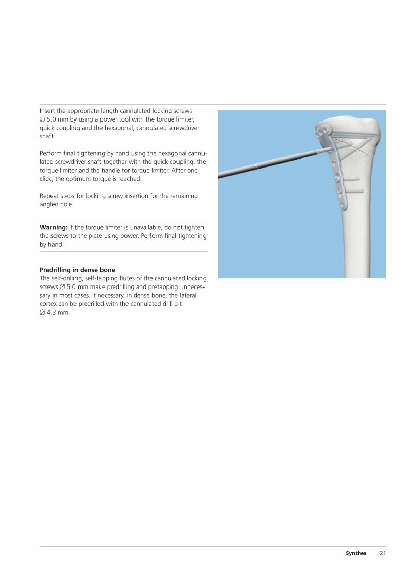
Insert the appropriate length cannulated locking screws � 5.0 mm by using a power tool with the torque limiter,quick coupling and the hexagonal, cannulated screwdrivershaft.
Perform final tightening by hand using the hexagonal cannu-lated screwdriver shaft together with the quick coupling, thetorque limiter and the handle for torque limiter. After oneclick, the optimum torque is reached.
Repeat steps for locking screw insertion for the remainingangled hole.
Warning: If the torque limiter is unavailable, do not tightenthe screws to the plate using power. Perform final tighteningby hand
Predrilling in dense boneThe self-drilling, self-tapping flutes of the cannulated lockingscrews � 5.0 mm make predrilling and pretapping unneces-sary in most cases. If necessary, in dense bone, the lateralcortex can be predrilled with the cannulated drill bit � 4.3 mm.
0X6.000.360_AB.qxp:0X6.000.360_AB 04.12.2008 15:05 Uhr Seite 21
22 Synthes LCP Medial Proximal Tibial Plate 4.5/5.0 Technique Guide
Surgical Technique
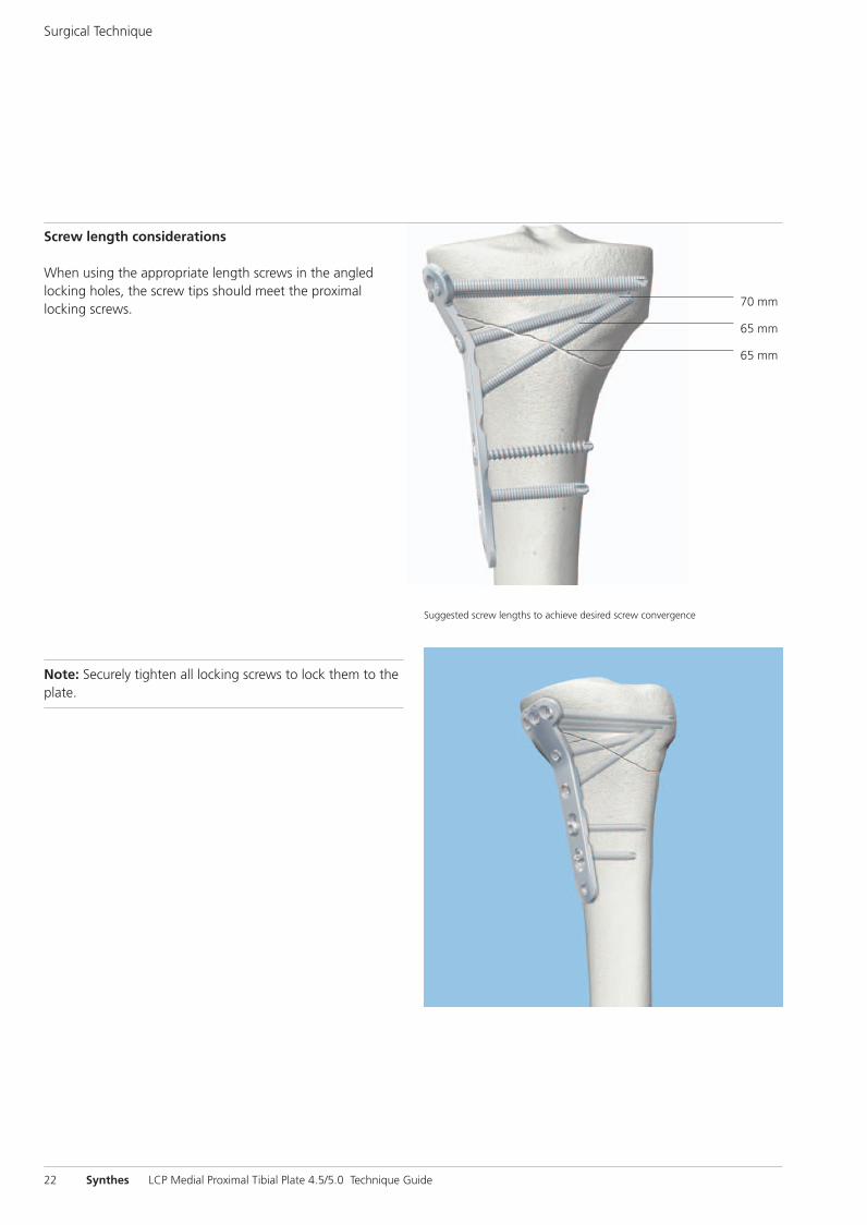
Screw length considerations
When using the appropriate length screws in the angledlocking holes, the screw tips should meet the proximal locking screws.
Note: Securely tighten all locking screws to lock them to theplate.
Suggested screw lengths to achieve desired screw convergence
70 mm
65 mm
65 mm
0X6.000.360_AB.qxp:0X6.000.360_AB 04.12.2008 15:05 Uhr Seite 22
Synthes 23
Instruments for Minimally InvasiveOsteosynthesis
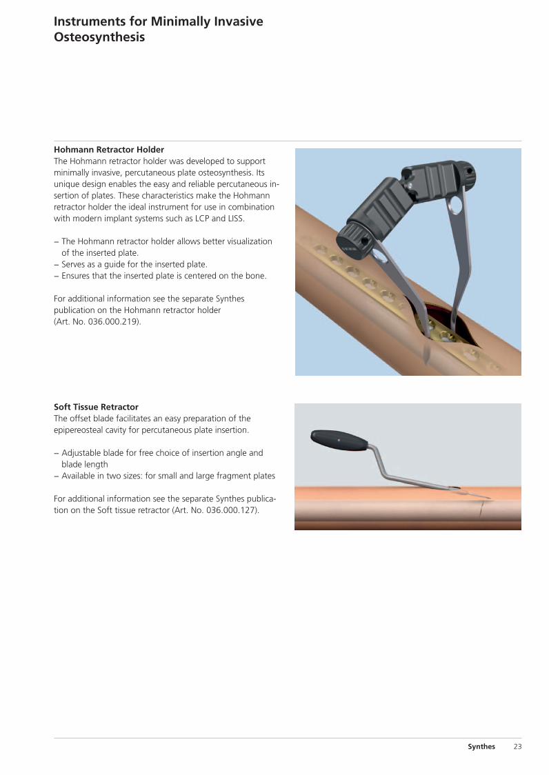
Hohmann Retractor HolderThe Hohmann retractor holder was developed to supportminimally invasive, percutaneous plate osteosynthesis. Itsunique design enables the easy and reliable percutaneous in-sertion of plates. These characteristics make the Hohmannretractor holder the ideal instrument for use in combinationwith modern implant systems such as LCP and LISS.
− The Hohmann retractor holder allows better visualizationof the inserted plate.
− Serves as a guide for the inserted plate.− Ensures that the inserted plate is centered on the bone.
For additional information see the separate Synthes publication on the Hohmann retractor holder(Art. No. 036.000.219).
Soft Tissue RetractorThe offset blade facilitates an easy preparation of theepipereosteal cavity for percutaneous plate insertion.
− Adjustable blade for free choice of insertion angle andblade length
− Available in two sizes: for small and large fragment plates
For additional information see the separate Synthes publica-tion on the Soft tissue retractor (Art. No. 036.000.127).
0X6.000.360_AB.qxp:0X6.000.360_AB 04.12.2008 15:05 Uhr Seite 23
24 Synthes LCP Medial Proximal Tibial Plate 4.5/5.0 Technique Guide
Plates
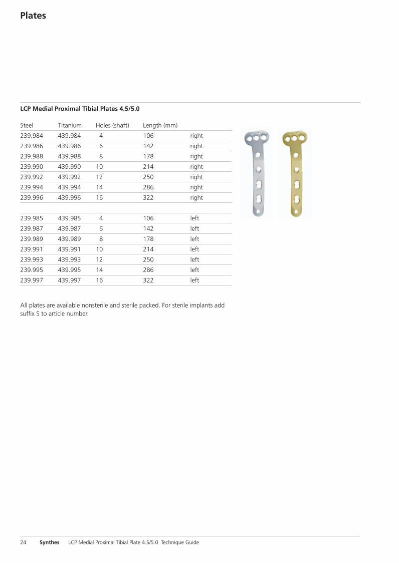
LCP Medial Proximal Tibial Plates 4.5/5.0
Steel Titanium Holes (shaft) Length (mm)
239.984 439.984 4 106 right
239.986 439.986 6 142 right
239.988 439.988 8 178 right
239.990 439.990 10 214 right
239.992 439.992 12 250 right
239.994 439.994 14 286 right
239.996 439.996 16 322 right
239.985 439.985 4 106 left
239.987 439.987 6 142 left
239.989 439.989 8 178 left
239.991 439.991 10 214 left
239.993 439.993 12 250 left
239.995 439.995 14 286 left
239.997 439.997 16 322 left
All plates are available nonsterile and sterile packed. For sterile implants addsuffix S to article number.
0X6.000.360_AB.qxp:0X6.000.360_AB 04.12.2008 15:05 Uhr Seite 24
Synthes 25
Screws
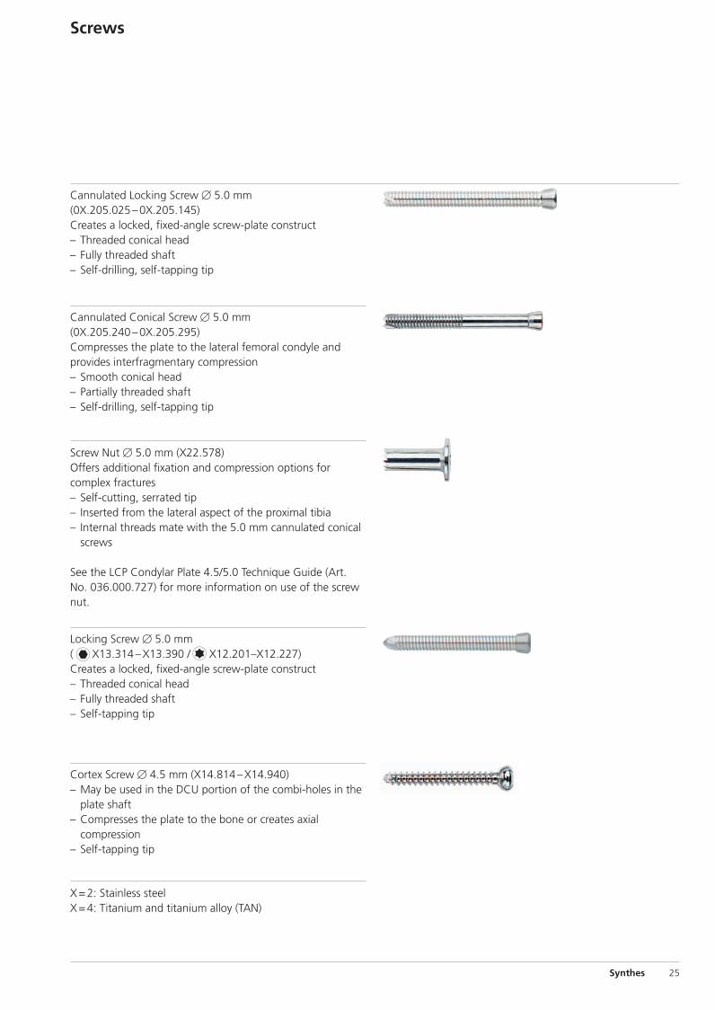
Cannulated Locking Screw � 5.0 mm(0X.205.025 – 0X.205.145)Creates a locked, fixed-angle screw-plate construct– Threaded conical head– Fully threaded shaft– Self-drilling, self-tapping tip
Cannulated Conical Screw � 5.0 mm(0X.205.240 – 0X.205.295)Compresses the plate to the lateral femoral condyle and provides interfragmentary compression– Smooth conical head– Partially threaded shaft– Self-drilling, self-tapping tip
Screw Nut � 5.0 mm (X22.578)Offers additional fixation and compression options for complex fractures– Self-cutting, serrated tip– Inserted from the lateral aspect of the proximal tibia– Internal threads mate with the 5.0 mm cannulated conical
screws
See the LCP Condylar Plate 4.5/5.0 Technique Guide (Art.No. 036.000.727) for more information on use of the screwnut.
Locking Screw � 5.0 mm( X13.314 – X13.390 / X12.201–X12.227)Creates a locked, fixed-angle screw-plate construct– Threaded conical head– Fully threaded shaft– Self-tapping tip
Cortex Screw � 4.5 mm (X14.814 – X14.940)– May be used in the DCU portion of the combi-holes in the
plate shaft– Compresses the plate to the bone or creates axial
compression– Self-tapping tip
X = 2: Stainless steelX = 4: Titanium and titanium alloy (TAN)
0X6.000.360_AB.qxp:0X6.000.360_AB 04.12.2008 15:05 Uhr Seite 25
26 Synthes LCP Medial Proximal Tibial Plate 4.5/5.0 Technique Guide
Cannulated Locking and Cannulated Conical Screws� 5.0 mmThe screw design enhances fixation and facilitates the surgical procedure.
Screw headThe conical head simplifies alignment in the plate hole. Thisis of particular importance when using locking screws. Thethreaded screw head must align with the plate hole threadsto provide a secure screw-plate construct. To ensure properalignment and prevent cross-threading, the appropriatethreaded wire guide or drill guide must always be used.
Large diameter screw coreThe large diameter screw core improves bending and shearstrength, and distributes the load over a larger area in thebone.
Thread profileThe shallow thread profile of the locking screws is necessaryto provide a larger core. This is appropriate since lockingscrews do not rely on compression between the plate andthe bone to maintain stability. When required, interfragmen-tary compression can be achieved with the partially threadedcannulated conical screws, especially when near the articularsurface.
Screws
0X6.000.360_AB.qxp:0X6.000.360_AB 04.12.2008 15:05 Uhr Seite 26
Synthes 27
Drill and Wire Guides
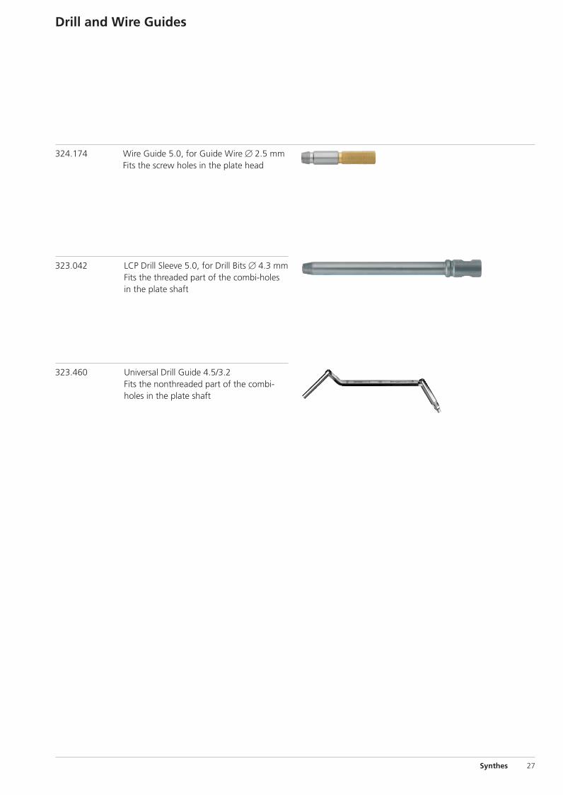
324.174 Wire Guide 5.0, for Guide Wire � 2.5 mmFits the screw holes in the plate head
323.042 LCP Drill Sleeve 5.0, for Drill Bits � 4.3 mmFits the threaded part of the combi-holesin the plate shaft
323.460 Universal Drill Guide 4.5/3.2Fits the nonthreaded part of the combi-holes in the plate shaft
0X6.000.360_AB.qxp:0X6.000.360_AB 04.12.2008 15:05 Uhr Seite 27
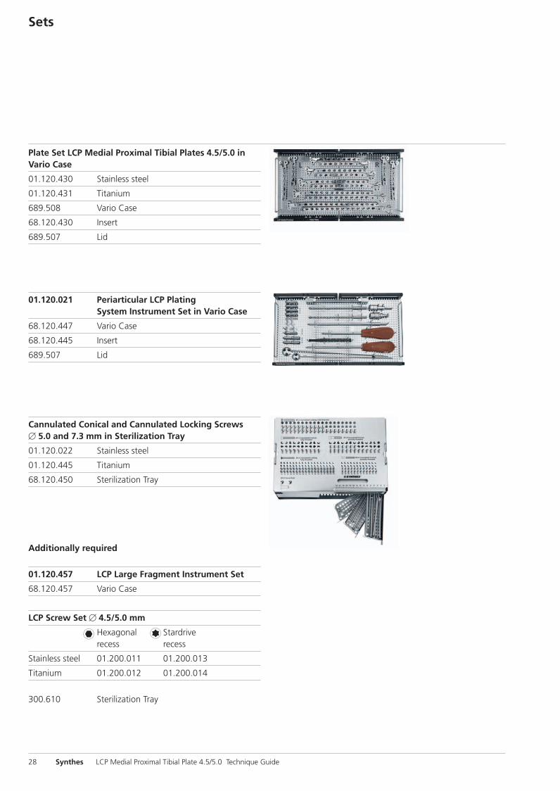
Additionally required
01.120.457 LCP Large Fragment Instrument Set
68.120.457 Vario Case
LCP Screw Set � 4.5/5.0 mm
Hexagonal Stardriverecess recess
Stainless steel 01.200.011 01.200.013
Titanium 01.200.012 01.200.014
300.610 Sterilization Tray
Sets
Plate Set LCP Medial Proximal Tibial Plates 4.5/5.0 inVario Case
01.120.430 Stainless steel
01.120.431 Titanium
689.508 Vario Case
68.120.430 Insert
689.507 Lid
01.120.021 Periarticular LCP PlatingSystem Instrument Set in Vario Case
68.120.447 Vario Case
68.120.445 Insert
689.507 Lid
Cannulated Conical and Cannulated Locking Screws� 5.0 and 7.3 mm in Sterilization Tray
01.120.022 Stainless steel
01.120.445 Titanium
68.120.450 Sterilization Tray
28 Synthes LCP Medial Proximal Tibial Plate 4.5/5.0 Technique Guide
0X6.000.360_AB.qxp:0X6.000.360_AB 04.12.2008 15:05 Uhr Seite 28

0X6.000.360_AB.qxp:0X6.000.360_AB 04.12.2008 15:05 Uhr Seite Cvr3

Synthes GmbHEimattstrasse 3CH-4436 Oberdorfwww.synthes.com 0123Presented by: 03
6.00
0.36
0 SE
_128
407
AB
3108
0018
©
05/
2008
Syn
thes
, Inc
. or
its a
ffili
ates
A
ll rig
hts
rese
rved
LC
P, S
tard
rive
and
Vario
Cas
e ar
e tr
adem
arks
of
Synt
hes,
Inc.
or
its a
ffili
ates
Ö036.000.360öAB|ä
0X6.000.360_AB.qxp:0X6.000.360_AB 04.12.2008 15:05 Uhr Seite Cvr4