Embed Size (px)
Citation preview
MARITIMEBusbarSolutions
A Phoenix Mecano Partner Company
Manufactured in Frederick, MD
Technology For Electrical Energy
www.TefelenAmerica.com
CONTENTSTechnical Specifications .......................................................................................................................................................................................02
Features .................................................................................................................................................................................................................02
Electrical Specifications .......................................................................................................................................................................................03
Manufacturing Options .........................................................................................................................................................................................03
Manufacturing Process .........................................................................................................................................................................................03
Connection Sleeves ..............................................................................................................................................................................................04
Fixation Systems ...................................................................................................................................................................................................05
Bulkhead Penetrations .........................................................................................................................................................................................05
Grounding..............................................................................................................................................................................................................05
Maritime Features & Benefits ...............................................................................................................................................................................06
Historical Research and Observations ................................................................................................................................................................08
Type Tests/Routine Tests .....................................................................................................................................................................................10
Standard Set of Delivered Equipment .................................................................................................................................................................10
Maritime Busbar Solutions Technology For Electrical Energy
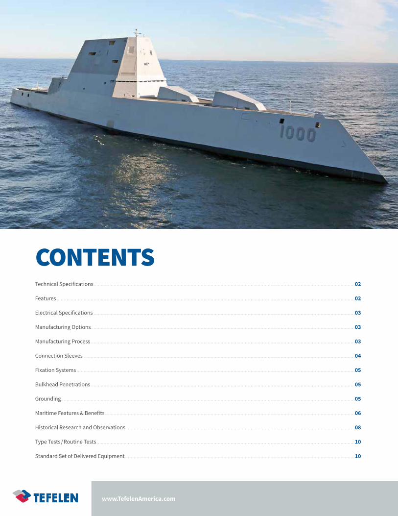
Technical Specifications
Features• Small overall dimensions, up to 40% less space needed than cable systems
• Tight bending radius, up to 80% tighter bend radius than cable systems
• Designed and built using a modular installation approach
• Suitable for outdoor & indoor applications
• Ambient temperature from -50° to +55 °C
• Environmental protection up to IP68, Suitable for marine & wet environments
• High resistance to ultraviolet, aggressive environments
• Low Maintenance
• High degree of fire withstand, passed Navy 3-hour flame test
• No phase to phase short circuit possible
• Partial discharge free
• Modular distribution kit, simply bolted together with no special tools required
• Natural (air) cooling
• Very low power losses (I²R)
• Lowest lifecycle costs for end clients
MR Busbars
Type of Insulation Epoxy Resin Impregnated Paper
Nominal voltage AC, kV Up to 36
Nominal current AC, A Up to 12,000
Nominal voltage DC, kV Up to 60
Nominal current DC, A Up to 14,000
Operating ambient temperature, °C From -60° to +55°C
Degree of protection Up to IP68 Inclusive
High chemical resistance Yes
SOLID INSULATED BUSBAR ISOBUS MR
02
www.TefelenAmerica.com
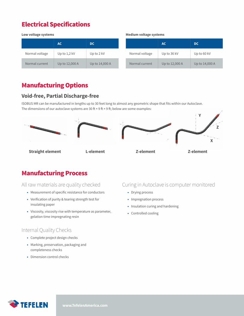
Straight element L-element Z-element Z-element
Y
Z
X
Manufacturing Process
Manufacturing OptionsVoid-free, Partial Discharge-freeISOBUS MR can be manufactured in lengths up to 30 feet long to almost any geometric shape that fits within our Autoclave. The dimensions of our autoclave systems are 30 ft × 9 ft × 9 ft; below are some examples:
Electrical Specifications
All raw materials are quality checked• Measurement of specific resistance for conductors
• Verification of purity & tearing strength test for insulating paper
• Viscosity, viscosity rise with temperature as parameter, gelation time impregnating resin
Curing in Autoclave is computer monitored• Drying process
• Impregnation process
• Insulation curing and hardening
• Controlled cooling
Internal Quality Checks• Complete project design checks
• Marking, preservation, packaging and completeness checks
• Dimension control checks
Low voltage systems
AC DC
Normal voltage Up to 1,2 kV Up to 2 kV
Normal current Up to 12,000 A Up to 14,000 A
Medium voltage systems
AC DC
Normal voltage Up to 36 kV Up to 60 kV
Normal current Up to 12,000 A Up to 14,000 A

Maritime Busbar Solutions Technology For Electrical Energy
The basic conductor (1) can be aluminum or copper and either solid or hollow, depending upon amperage. The conductor is wrapped by alternating insulated crepe paper layers and layers of semi-conducting paper (2) in order to provide the capacitive grading needed. A vacuum system pulls epoxy resin through the entire length of the element to ensure a void free, partial discharge-free composite dielectric (3) insulation. The Grounding layer ensures safety while operational (4). To make connections easy between busbar, and other terminating equipment, there are flat terminals (5) at the ends of each element.
For low voltage solid insulated busbar isobus MR solutions up to 1.2 kV there are no capacitive grading layers and no grounding layer required.
FIGURE 1The busbar element’s construction drawing1. Conductor (Al, Cu)
2. Capacitive grading
3. Epoxy-impregnated paper wrapping
4. Grounding layer
5. Flat terminal
Connection SleevesBusbars have capacitive control therefore there is a red grading length on both ends. Separate busbar elements are connected to each other by use of bus expansion compensators, which are flexible copper laminate connections. These allow for thermal expansion and contraction. They also allow build tolerances of up to ±2 inches per connection.
The connection is then enclosed by a fully insulated connecting sleeve which has pressure-tight flanges on both sides. In order to balance the potential between the current carrying conductor and the internal surface of the connecting sleeve, a metal ring with contact spring is provided.
04
www.TefelenAmerica.com
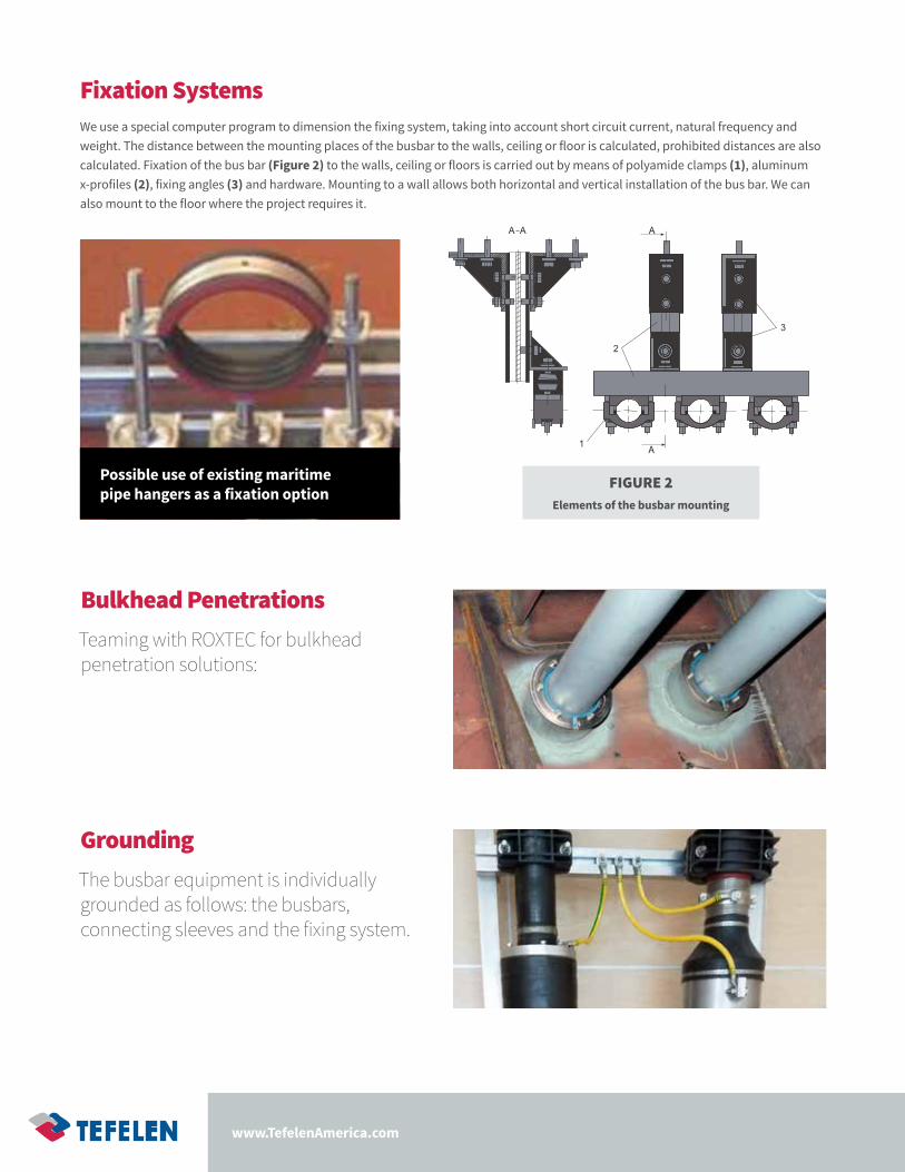
Fixation SystemsWe use a special computer program to dimension the fixing system, taking into account short circuit current, natural frequency and weight. The distance between the mounting places of the busbar to the walls, ceiling or floor is calculated, prohibited distances are also calculated. Fixation of the bus bar (Figure 2) to the walls, ceiling or floors is carried out by means of polyamide clamps (1), aluminum x-profiles (2), fixing angles (3) and hardware. Mounting to a wall allows both horizontal and vertical installation of the bus bar. We can also mount to the floor where the project requires it.
A
Bulkhead PenetrationsTeaming with ROXTEC for bulkhead penetration solutions:
GroundingThe busbar equipment is individually grounded as follows: the busbars, connecting sleeves and the fixing system.
FIGURE 2Elements of the busbar mounting
Possible use of existing maritime pipe hangers as a fixation option
Maritime Busbar Solutions Technology For Electrical Energy
Insulated Bus Pipe• Very mature technology globally applied (TRL ~9)
• Modular construction and easy installation with minimal maintenance
• Prefab in first 1/3 of shipbuilding timeline and install rather than last 1/3
• Ideal for >1,000V and >1000Amps which requires multiple cables
• Hollow pipe ideal for AC; solid ideal for DC
• Navy spent $2.5M testing to MIL-STDs in 2005; MIL-S 901D shock, MIL-S 461 EMI, Toxicity, Survivability, etc.
• Multiple joining methods available (bolted, welded, flexible)
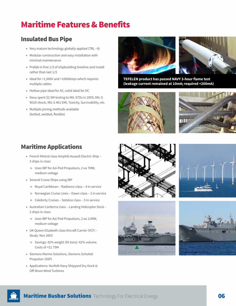
TEFELEN product has passed NAVY 3-hour flame test (leakage current remained at 10mA; required <200mA)
Maritime Features & Benefits
Maritime Applications• French Mistral class Amphib Assault Electric Ship –
3 ships in class
▷ Uses IBP for Azi-Pod Propulsors, 2 ea 7MW, medium voltage
• Several Cruise Ships using IBP
▷ Royal Caribbean – Radiance class – 4 in service
▷ Norwegian Cruise Lines – Dawn class – 2 in service
▷ Celebrity Cruises – Solstice class – 5 in service
• Australian Canberra class – Landing Helicopter Dock – 2 ships in class
▷ Uses IBP for Azi-Pod Propulsors, 2 ea 11MW, medium voltage
• UK Queen Elizabeth class Aircraft Carrier (VCF) – Study: Nov 2003
▷ Savings: 42% weight (95 tons): 42% volume. Costs of >$1.75M
• Siemens Marine Solutions, Siemens Schottel Propulsor (SSP)
• Applications: Norfolk Navy Shipyard Dry Dock 8; Off Shore Wind Turbines
06
www.TefelenAmerica.com
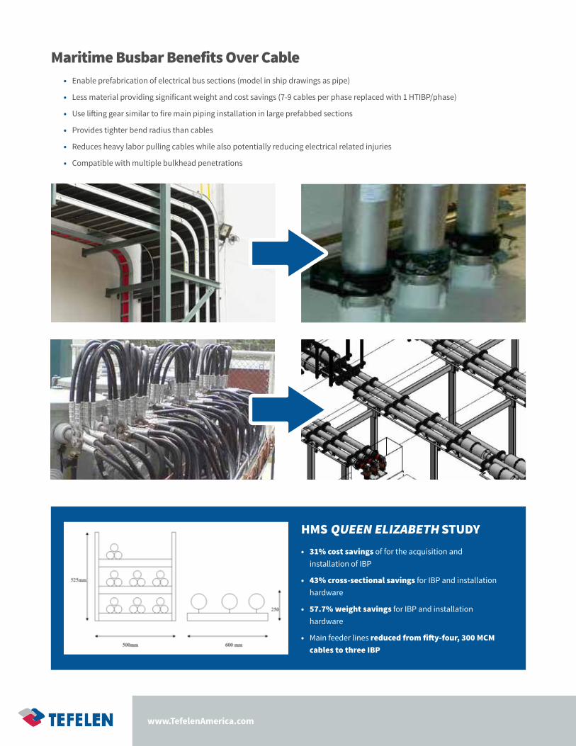
Maritime Busbar Benefits Over Cable• Enable prefabrication of electrical bus sections (model in ship drawings as pipe)
• Less material providing significant weight and cost savings (7-9 cables per phase replaced with 1 HTIBP/phase)
• Use lifting gear similar to fire main piping installation in large prefabbed sections
• Provides tighter bend radius than cables
• Reduces heavy labor pulling cables while also potentially reducing electrical related injuries
• Compatible with multiple bulkhead penetrations
HMS QUEEN ELIZABETH STUDY• 31% cost savings of for the acquisition and
installation of IBP
• 43% cross-sectional savings for IBP and installation hardware
• 57.7% weight savings for IBP and installation hardware
• Main feeder lines reduced from fifty-four, 300 MCM cables to three IBP
Maritime Busbar Solutions Technology For Electrical Energy
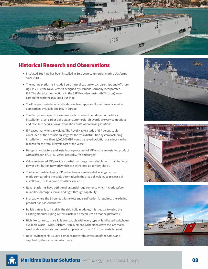
Historical Research and Observations• Insulated Bus Pipe has been installed in European commercial marine platforms
since 2001.
• The marine platforms include liquid natural gas tankers, cruise ships and offshore rigs. In 2010, the Naval vessels designed by Siemens Germany incorporated IBP. The electrical connections in the SSP Propulsor (Azimuth Thruster) were completed with the Insulated Bus Pipe.
• The European installation methods have been approved for commercial marine applications by Lloyds and DNV in Europe.
• The European shipyards save time and costs due to modular on the block installation at an earlier build stage. Commercial shipyards are very competitive and calculate acquisition & installation costs when buying solutions.
• IBP saves many tons in weight. The Royal Navy’s study of IBP versus cable concluded at the acquisition stage for the total distribution system including installation, more than 1,000,000 GBP could be saved. Additional savings can be realized for the total lifecycle cost of the vessel.
• Design, manufacture and installation processes of IBP ensure an installed product with a lifespan of 35 - 50 years. Basically, “fit and forget.”
• Value engineered IBP provide a partial discharge free, reliable, zero maintenance power distribution network which can withstand up to 450g shock.
• The benefits of deploying IBP technology are substantial savings can be made compared to the cable alternative in the areas of weight, space, ease of installation, I²R losses and total lifecycle cost.
• Naval platforms have additional essential requirements which include safety, reliability, damage survival and fight through capability.
• In areas where the 3 hour gas flame test and certification is required, the existing product has passed this test.
• Build strategy is to install in the ship build modules, this is equal to using the existing modular piping systems installed procedures on marine platforms.
• High flex connectors are fully compatible with every type of land based switchgear available world – wide. (Alstom, ABB, Siemens, Schneider, Areva etc. are major worldwide electrical component suppliers who use IBP in their installations)
• Naval switchgear is usually a smaller, more robust version of the same, and supplied by the same manufacturers.
08
www.TefelenAmerica.com
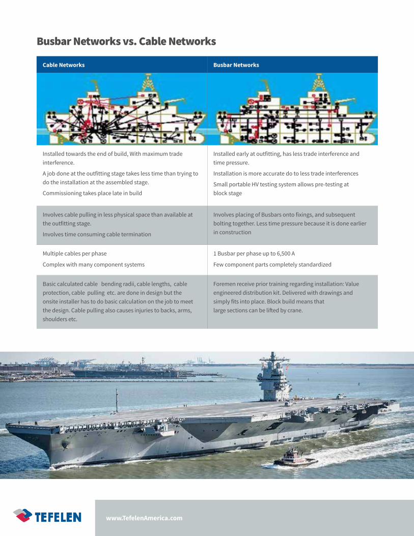
Busbar Networks vs. Cable Networks
Cable Networks Busbar Networks
Installed towards the end of build, With maximum trade interference.
A job done at the outfitting stage takes less time than trying to do the installation at the assembled stage.
Commissioning takes place late in build
Installed early at outfitting, has less trade interference and time pressure.
Installation is more accurate do to less trade interferences
Small portable HV testing system allows pre-testing at block stage
Involves cable pulling in less physical space than available at the outfitting stage.
Involves time consuming cable termination
Involves placing of Busbars onto fixings, and subsequent bolting together. Less time pressure because it is done earlier in construction
Multiple cables per phase
Complex with many component systems
1 Busbar per phase up to 6,500 A
Few component parts completely standardized
Basic calculated cable bending radii, cable lengths, cable protection, cable pulling etc. are done in design but the onsite installer has to do basic calculation on the job to meet the design. Cable pulling also causes injuries to backs, arms, shoulders etc.
Foremen receive prior training regarding installation: Value engineered distribution kit. Delivered with drawings and simply fits into place. Block build means that large sections can be lifted by crane.
Maritime Busbar Solutions Technology For Electrical Energy
Type TestsThe ISOBUS MR busbar system is a type tested system for which the following tests are performed:
• Dry power-frequency voltage withstand
• Dry lightning impulse voltage withstand
• Temperature rise
• Verification of thermal short-time current withstand
• Verification of dimensions
• Vibration and Shock tests respectively Seismic tests
• Tests for mechanical stability
• Fire tests
• Climate tests to ensure the performance during operation, transportation and storage
• Ingress Protection (IP) tests
HARDWARE INCLUDES:• Bus bar elements
• Connecting sleeves
• Flexible or high flexible bus expansion compensators for connection of elements to each other and connections of the bus bar to equipment
• Fixation system, including aluminum x-profiles and hardware
• Grounding cable
• Nuts and bolts
• Warranty card
• Test reports
SOFTWARE INCLUDES:• Packing list
• The set of assembly factory drawings
• Installation instruction manual
• Operation manual
• Test reports for each element
PACKINGAccording to the design documentation, busbars and components are packed and fastened into sturdy wooden boxes. Separately delivered small size assembly units, details and fasteners are packed into wooden boxes according to the design documentation.
Standard Set of Delivered EquipmentMR modular distribution kit is delivered on site complete with all components/documents required for installation. The delivery package is created according to design documentation and rigorously checked prior to dispatch. The list below shows the main elements.
Routine TestsAfter manufacturing process, each element of a busbar system is subject to the following tests:
• Dimensional check of the conductors
• Dry power-frequency voltage withstand
• Measurement of partial discharge quantity
• Measurement of dielectric dissipation factor (tan δ) and capacitance at ambient temperature
• Final visual inspection
10
7330 Executive Way Frederick, MD 21704
www.TefelenAmerica.com