Embed Size (px)
Citation preview

Telecommunication Networks
Distributed Parameter Networks
Distributed Parameter Networks 1.
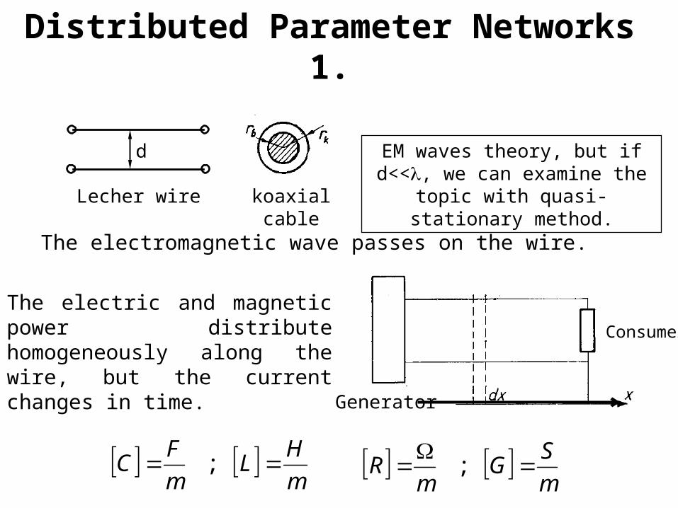
The electric and magnetic power distribute homogeneously along the wire, but the current changes in time.
d
Lecher wire koaxial cable
The electromagnetic wave passes on the wire.
EM waves theory, but if d<<, we can examine the topic
with quasi-stationary method.
m
HL
m
FC ;
m
SG
mR
;
Generator
Consumer
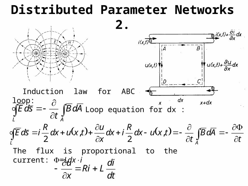
Induction law for ABCD loop:
AL
AdBt
sdE
t
AdBt
txudxR
idxx
utxudx
RisdE
AL
,2
,2
The flux is proportional to the current: =Ldxi
dt
diLRi
x
u
Loop equation for dx :
Distributed Parameter Networks 2.
Rearranging:
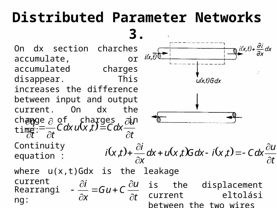
On dx section charches accumulate, or accumulated charges disappear. This increases the difference between input and output current. On dx the change of charges in time:
t
uCdxtxuCdx
tt
q
,
t
uCGu
x
i
is the displacement current eltolási between the two wires
Continuity equation : t
uCdxtxiGdxtxudx
x
itxi
,,,
where u(x,t)Gdx is the leakage current
Distributed Parameter Networks 3.
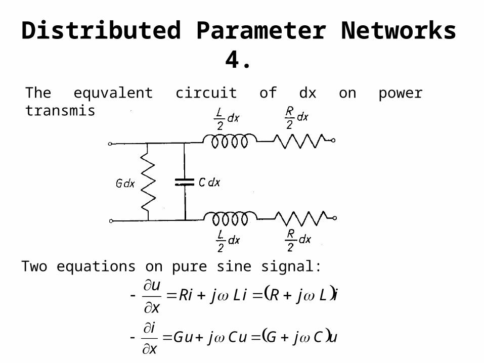
The equvalent circuit of dx on power transmission line:
iLjRLijRix
u
uCjGCujGux
i
Two equations on pure sine signal:
Distributed Parameter Networks 4.
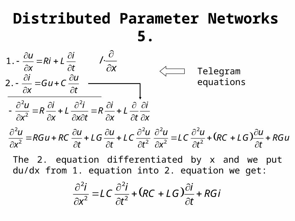
The 2. equation differentiated by x and we put du/dx from 1. equation into 2. equation we get:
t
iLRi
x
u
.1Telegram equations
RGit
iLGRC
t
iLC
x
i
2
2
2
2
t
uCGu
x
i
.2
x
/
x
i
tL
x
iR
tx
iL
x
iR
x
u
2
2
2
2
2
2
2
t
uLC
t
uLG
t
uRCRGu
x
u
RGu
t
uLGRC
t
uLC
x
u
2
2
2
2
Distributed Parameter Networks 5.
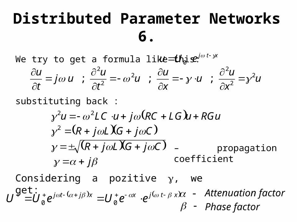
We try to get a formula like this:
ux
uu
x
uu
t
uuj
t
u 22
22
2
2
; ; ;
substituting back :
xtjeUu 0
RGuuLGRCjuLCu 22
CjGLjR 2
CjGLjR j
xtjxxjtj eeUeUU 00
Considering a pozitive , we get:
tényezősicsillapítá zőfázisténye
– propagation coefficient
Distributed Parameter Networks 6.
Attenuation factor
Phase factor
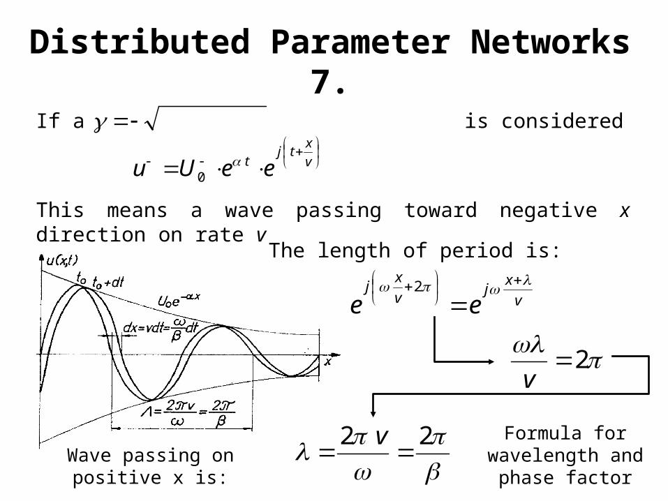
If a is considered
v
xtj
t eeUu 0
This means a wave passing toward negative x direction on rate v
v
xj
v
xj
ee
2
2
v
The length of period is:
22
v Formula for
wavelength and phase factor
Wave passing on positive x is:
Distributed Parameter Networks 7.
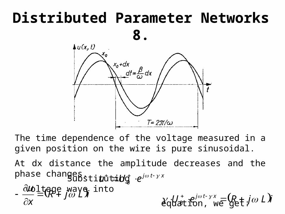
The time dependence of the voltage measured in a given position on the wire is pure sinusoidal.
At dx distance the amplitude decreases and the phase changes. Substituting voltage wave into
equation, we get:
xtjeUu 0
iLjRx
u
iLjReU xtj 0
Distributed Parameter Networks 8.
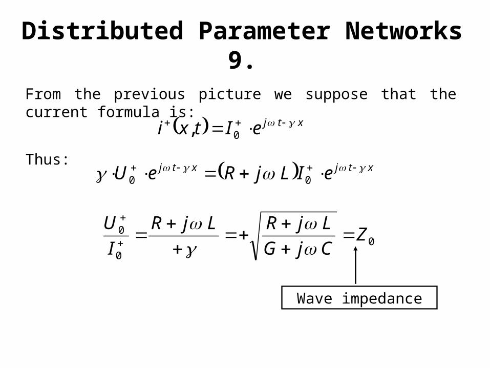
From the previous picture we suppose that the current formula is:
xtjeItxi 0,
Thus: xtjxtj eILjReU 0
0
00
0
Z
CjG
LjRLjR
I
U
Wave impedance
Distributed Parameter Networks 9.
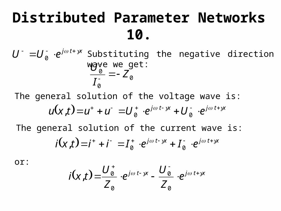
Substituting the negative direction wave we get:
xtjeUU 0
The general solution of the voltage wave is:
xtjxtj eUeUuutxu 00,
00
0 ZI
U
xtjxtj eIeIiitxi 00,
or:
xtjxtj eZ
Ue
Z
Utxi
0
0
0
0,
Distributed Parameter Networks 10.
The general solution of the current wave is:
thus
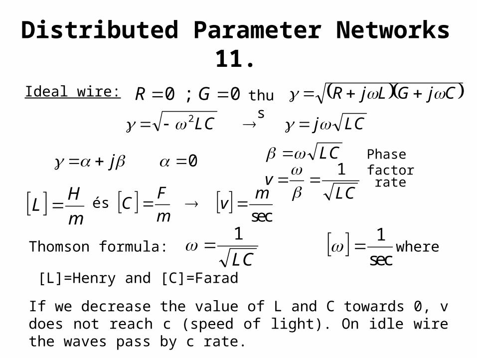
0;0 GR
Thomson formula: where
[L]=Henry and [C]=Farad
0 j
LCjLC 2
If we decrease the value of L and C towards 0, v does not reach c (speed of light). On idle wire the waves pass by c rate.
Phase factor
CjGLjR
LC
LCv
1
LC
1
sec
1
m
HL
sec
mv
m
FC
Ideal wire:
rate
és
Distributed Parameter Networks 11.
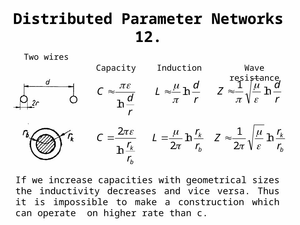
If we increase capacities with geometrical sizes the inductivity decreases and vice versa. Thus it is impossible to make a construction which can operate on higher rate than c.
rd
Cln
r
dL ln
r
dZ ln
1
b
k
rr
Cln
2
b
k
r
rL ln
2
b
k
r
rZ ln
2
1
Two wiresCapacity Induction Wave
resistance
Distributed Parameter Networks 12.
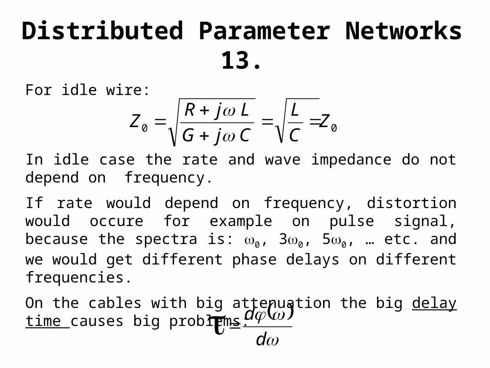
In idle case the rate and wave impedance do not depend on frequency.
If rate would depend on frequency, distortion would occure for example on pulse signal, because the spectra is: 0, 30, 50, … etc. and we would get different phase delays on different frequencies.
On the cables with big attenuation the big delay time causes big problems:
00
Z
C
L
CjG
LjRZ
For idle wire:
d
d
Distributed Parameter Networks 13.
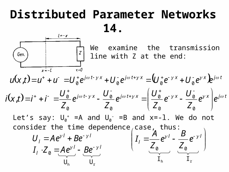
Let’s say: U0+ =A and U0
- =B and x=-l. We do not consider the time dependence case, thus:
tjxxxtjxtj eeUeUeUeUuutxu 0000,
We examine the transmission line with Z at the end:
tjxxxtjxtj eeZ
Ue
Z
Ue
Z
Ue
Z
Uiitxi
0
0
0
0
0
0
0
0,
lll BeAeU
lll BeAeZI 0
ll
l eZ
Be
Z
AI
00
Ih IrUh Ur
Distributed Parameter Networks 14.
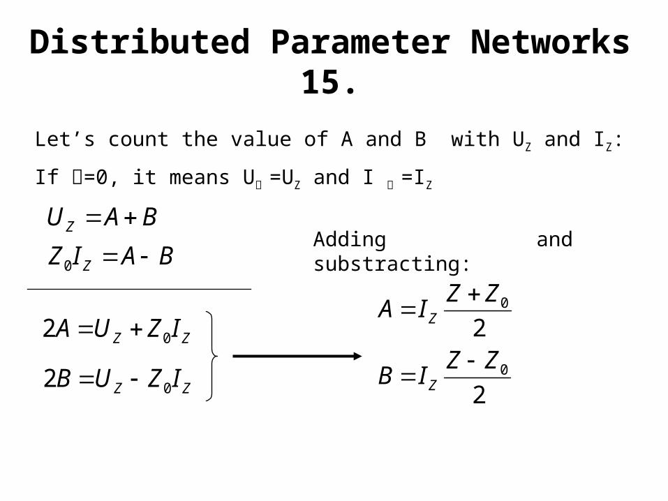
Adding and substracting:BAUZ
Let’s count the value of A and B with UZ and IZ:
If =0, it means U =UZ and I =IZ
BAIZ Z 0
ZZ IZUA 02
ZZ IZUB 02
20ZZ
IA Z
20ZZ
IB Z
Distributed Parameter Networks 15.
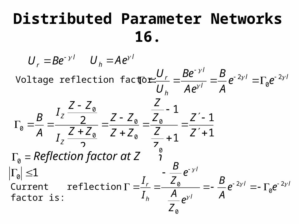
Current reflection factor is:
lll
l
h
r eeA
B
Ae
Be
U
U 20
2
Voltage reflection factor:
lr BeU l
h AeU
1
1
1
1
2
2
0
0
0
0
0
0
0
Z
Z
ZZZZ
ZZ
ZZZZ
I
ZZI
A
B
Z
Z
helyénlezárásareflexióa 0
10 ll
l
l
h
r eeA
B
eZA
eZB
I
I 20
2
0
0
Distributed Parameter Networks 16.
Reflection factor at Z
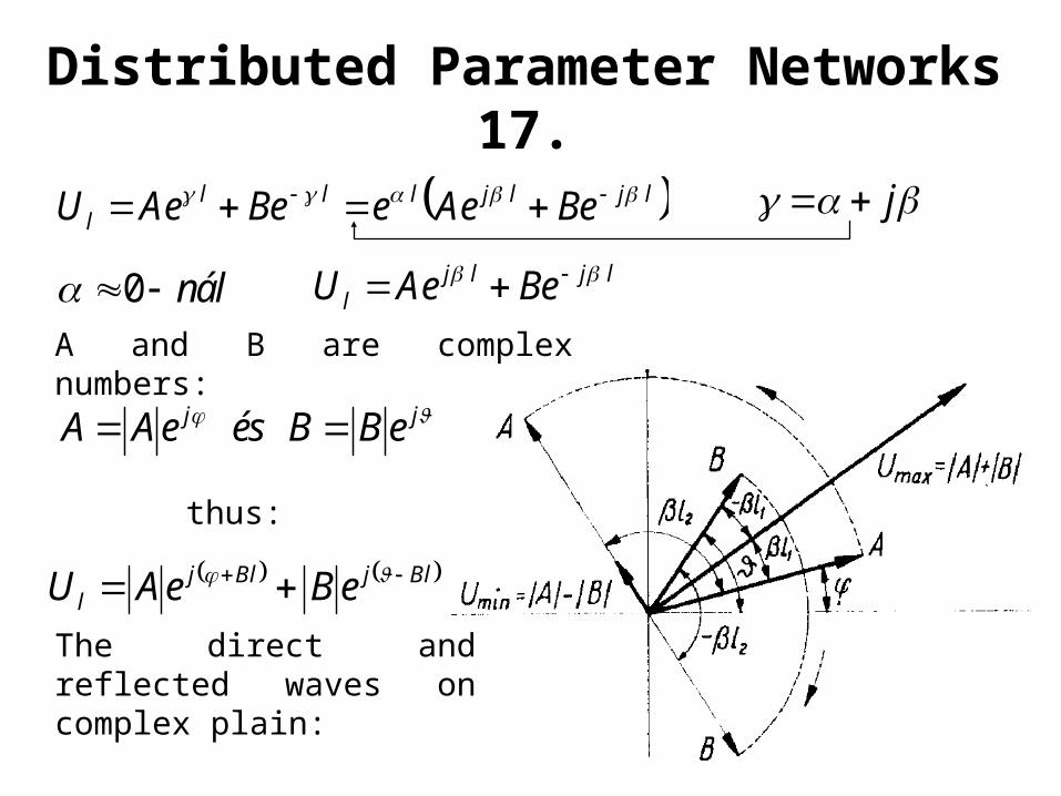
The direct and reflected waves on complex plain:
ljljllll BeAeeBeAeU j
nál0 ljljl BeAeU
A and B are complex numbers:
jj eBBéseAA
thus:
BljBljl eBeAU
Distributed Parameter Networks 17.
Where the two vectors are in phase voltage-maximum
Where the phase difference is 180o voltage-minimum
If ZZ0
along the line standing waves are self created
If Z=Z0 , there are not standing waves
0
00
0
ZZ
ZZ
Distributed Parameter Networks 18.
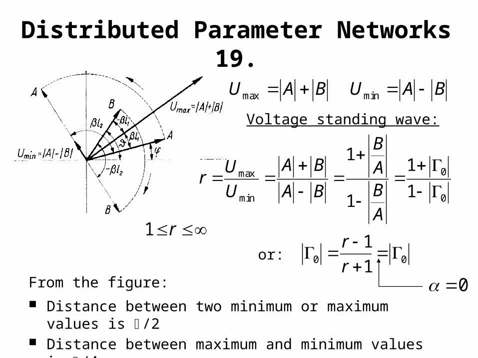
BAU max
Voltage standing wave:
BAU min
0
0
min
max
1
1
1
1
ABAB
BA
BA
U
Ur
From the figure: Distance between two minimum or maximum
values is /2 Distance between maximum and minimum values
is /4
00 1
1
r
rr1
or:
0
Distributed Parameter Networks 19.