Embed Size (px)
Citation preview
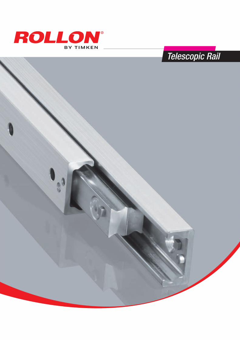
Telescopic Line
Interactive catalogson: www.rollon.com
General catalogueEnglish

We design and produce in order to support you
LOGISTICS
ROBOTICS
INDUSTRIAL MACHINERY
RAILWAY
V a l u e s
An international groupfor technology,
a local support for service
Over 40 years of know how in design and production
Appl ica t ions

INTERIORS AND ARCHITECTURE
MEDICAL
SPECIAL VEHICLES
AERONAUTICS
From a full range of standardproducts to fit-to-customersolutions for best perfomances
S o l u t i o n s
Collaboration
High level technical consulting
Cross competences in several industrial sectors for an effective problem-solving
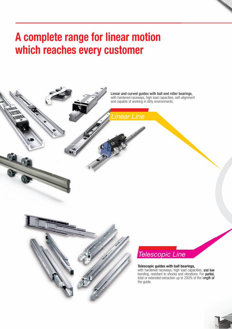
A complete range for linear motion which reaches every customer
Telescopic Line
Telescopic guides with ball bearings,with hardened raceways, high load capacities, and low bending, resistant to shocks and vibrations. For partial, total or extended extraction up to 200% of the length of the guide.
A global provider
of solutions
for applications
for linear motion
Linear Line
Linear and curved guides with ball and roller bearings,with hardened raceways, high load capacities, self-alignment and capable of working in dirty environments.
with hardened raceways, high load capacities, and low bending, resistant to shocks and vibrations. For partial, total or extended extraction up to 200% of the length of
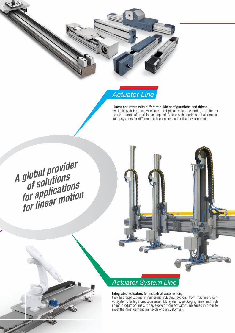
Actuator System LineIntegrated actuators for industrial automation,they fi nd applications in numerous industrial sectors: from machinery ser-vo systems to high precision assembly systems, packaging lines and high speed production lines. It has evolved from Actuator Line series in order to meet the most demanding needs of our customers.
Actuator Line
Linear actuators with different guide confi gurations and drives,available with belt, screw or rack and pinion drives according to different needs in terms of precision and speed. Guides with bearings or ball recircu-lating systems for different load capacities and critical environments.
A global provider
of solutions
for applications
for linear motion
Content
Telescopic RailTechnical features overview
1 Product explanation Telescopic Rail: Seven models with full and partial extension TR-2
2 Product cross sections TR-5
3 Technical data Performance characteristics and notes TR-7
4 Dimensions and load capacity ASN TR-8 DSS TR-12 DSS...S TR-14 DSB TR-16 DSD TR-17 DSE TR-19 DSC TR-21 DE TR-23 DE...S TR-26 DE...D TR-28 DE...Z TR-30 DBN TR-32 DMS TR-34 5 Technical instructions Telescopic rail selection, Static load check TR-36 Deflection TR-37 Static load TR-38 Service life TR-39 Speed, Extension and extraction force, Double-sided stroke, Temperature TR-42 Anticorrosive protection, Lubrication, Clearance and preload TR-43 Fixing screws TR-44 Installation instructions TR-45
Ordering key Ordering key with explanations TR-47
Telescopic Rail
FrontespizioTelescopicrail.indd 1 28/09/2018 13:21:09
Hegra Rail1 Product explanation Partial and full extension guides of different types HR-2
2 Product cross sections HR-4
3 Technical data Performance characteristics and notes HR-6
4 Load capacities and dimensions HTT HR-7 HVC HR-11 H1C HR-16 H1T HR-18 H2H HR-22 LTH HR-24 HGT HR-31 LTF HR-35 HGS HR-37 5 Accessories Locking, driving disc, damping HR-39 6 Technical information Selecting a suitable telescoping rail, Mounting tolerances, Life cycle, Load capacity, HR-40 Deflection, Operating temperature, Corrosion protection, Ball cage displacement, Moving force, Lubrication, Clearance and preload HR-41 Maintenance intervals, Assembly information HR-42
Ordering key Ordering key with explanations HR-43
Hegra Rail
FrontespizioHegra.indd 1 28/09/2018 13:17:25
Telerace1 Product explanation Telerace roller telescopic slides TLR-2
2 Overview product cross sections Series TLR-TLQ, series TLN-TQN, series TLAX-TQAX TLR-4
3 General characteristics TLR-TLQ series TLR-5 TLN-TQN and TLAX-TQAX series TLR-6
4 Dimensions and load capacity TLR TLR-7 TLQ TLR-10 TLN TLR-13 TQN TLR-15 TLAX TLR-18 TQAX TLR-20 Sizing of telescopic applications TLR-22 Verification of load capacity TLR-23 Lifetime calculation TLR-24
Ordering key
Telerace
www.rollon.com
Guida Prodotti
TELERACE_IT_OK.indd 1 28/01/2019 18:20:28
Light Rail1 Product explanation Light telescopic rails, with full or partial extension LR-2
2 Product cross sections LR-4
3 Technical data Performance characteristics and notes LR-5
4 Dimensions and load capacity LPS LR-6 LFS LR-7 LFS LR-8 LFS SC LR-9 LFS LR-10 LFX LR-11 Fixing screws LR-12 5 Technical instructions Load capacities LR-13 Speed, Temperature, Lubrication, Corrosion protection LR-14 Installation instructions LR-15
Ordering key Ordering key with explanations LR-16
Guides suitable for all applications
Light Rail
FrontespizioLightrail.indd 1 28/09/2018 13:18:15
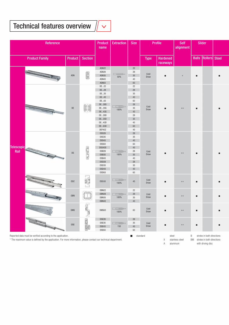
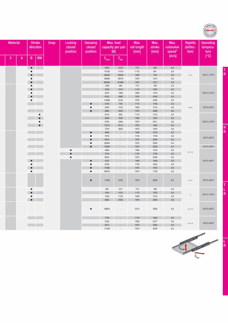
Reported data must be verified according to the application.
* The maximum value is defined by the application. For more information, please contact our technical department.
Telescopic Rail
ASN
ASN22
50%
22
ColdDraw n + n n
n 5934 4154 770 394 0,8
+++ -20°C/+170°C
ASN28 28 n 15736 11014 1170 601 0,8
ASN35 35 n 26520 18564 1490 759 0,8
ASN43 43 n 48596 34018 1970 1013 0,8
ASN63 63 n 88494 61946 1970 1013 0,8
DE
DE...22
100%
22
ColdDraw n ++ n n
n 1348 546 770 788 0,8
+++
-20°C/+170°C
DE...28 28 n 2338 1074 1170 1202 0,8
DE...35 35 n 3816 1586 1490 1518 0,8
DE...43 43 n 6182 2868 1970 2026 0,8
DE...63 63 n 14396 6124 1970 2026 0,8
DE...28S 28 n 2100 758 1170 1186 0,8
-20°C/+50°CDE...35S 35 n 3540 1574 1490 1510 0,8
DE...43S 43 n 5964 2522 1970 2066 0,8
DE...28D 28 n 2014 856 1170 1216 0,8
-20°C/+170°C
DE...35D 35 n 3460 1534 1490 1503 0,8
DE...43D 43 n 5784 2484 1970 2011 0,8
DE...63D 63 n 15512 6514 1970 1962 0,8
DEF43Z 43 7524 3830 1970 1923 0,8
DS
DSS28
100%
28
ColdDraw n ++ n n
n 4480 - 1490 1518 0,8
++++
-20°C/+80°CDSS35 35 n 7016 - 1730 1758 0,8
DSS43 43 n 9816 - 1970 2026 0,8
DSS63 63 n 25664 - 1970 2026 0,8
DSS43S 43 n 10208 - 1970 2026 0,8 -20°C/+50°C
DSB28 28 n 4480 - 1490 1518 0,8
-20°C/+80°C
DSB35 35 n 7016 - 1730 1758 0,8
DSB43 43 n 9816 - 1970 2026 0,8
DSD28 28 n n 5162 - 1490 1446 0,8
DSD35 35 n n 9736 - 1730 1630 0,8
DSD43 43 n n 11660 - 1970 1916 0,8
DSD63 63 n n 38018 - 1970 1758 0,8
DSC DSC43100%
43ColdDraw n ++ n n n 11058 4150 1970 2028 0,8 +++ -20°C/+80°C
DBN
DBN22
100%
22
ColdDraw n ++ n n
n 562 472 770 788 0,8
+ -20°C/+170°CDBN28 28 n 1244 1074 1170 1202 0,8
DBN35 35 n 1334 1120 1490 1518 0,8
DBN43 43 n 2662 2558 1970 2026 0,8
DMS DMS63100%
63ColdDraw n ++ n n n 39624 - 2210 2266 0,8 ++++ -20°C/+80°C
DSE
DSE28
150
28
ColdDraw n ++ n n
1702 - 1170 1803 0,8
++++ -20°C/+80°CDSE35 35 3182 - 1490 2277 0,8
DSE43 43 5012 - 1970 3039 0,8
DSE63 63 11344 - 1970 3039 0,8
steel
X stainless steel
A aluminum
B stroke in both directions
BM stroke in both directions
with driving disc
n standard
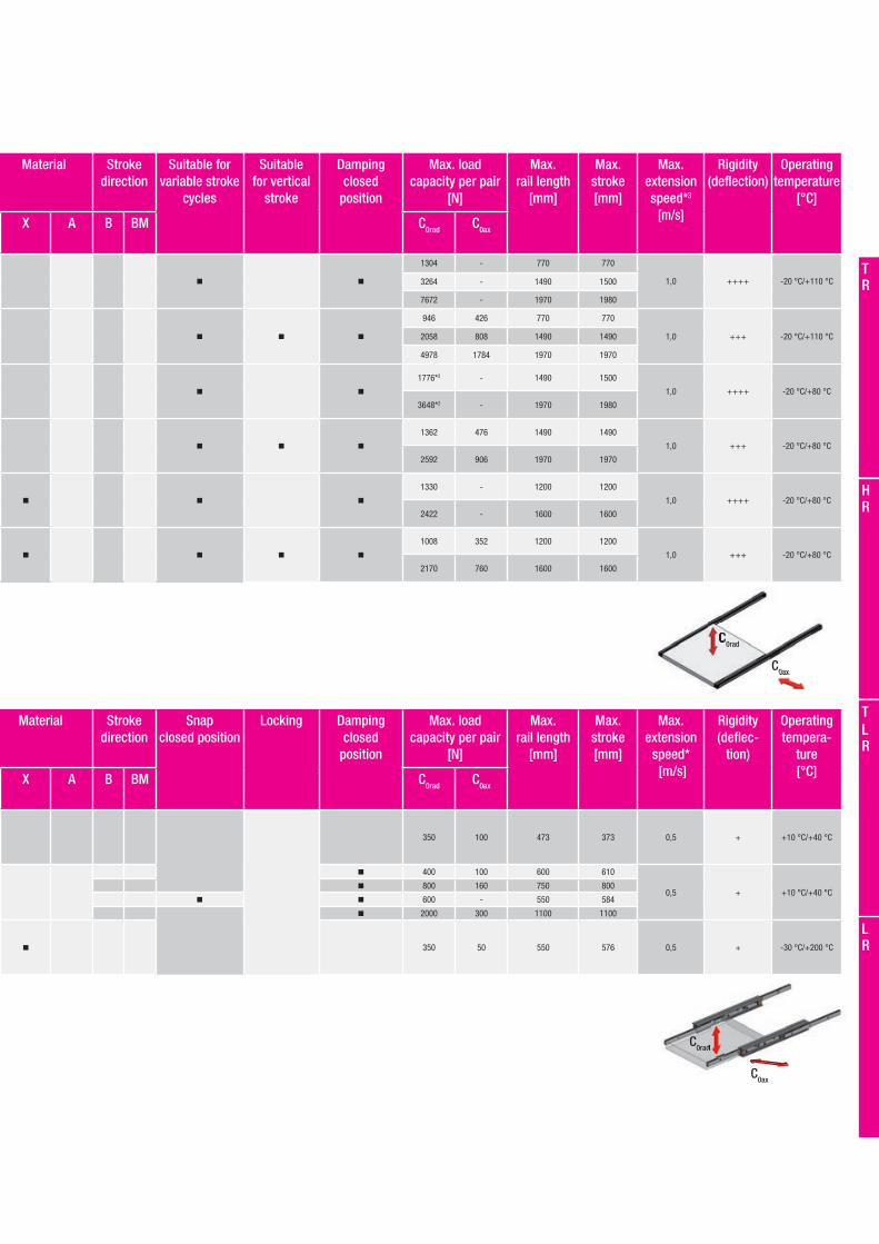
Technical features overview
Reference Product name
Extraction Size Profile Selfalignment
Slider Material Stroke direction
Snap Lockingclosed
position
Damping closed
position
Max. load capacity per pair
[N]
Max. rail length
[mm]
Max. stroke [mm]
Max. extension
speed* [m/s]
Rigidity(deflec-
tion)
Operating tempera-
ture[°C]Product Family Product Section Type Hardened
racewaysBalls Rollers Steel X A B BM C0rad C0ax
TR
HR
LR
TLR
Telescopic Rail
ASN
ASN22
50%
22
ColdDraw n + n n
n 5934 4154 770 394 0,8
+++ -20°C/+170°C
ASN28 28 n 15736 11014 1170 601 0,8
ASN35 35 n 26520 18564 1490 759 0,8
ASN43 43 n 48596 34018 1970 1013 0,8
ASN63 63 n 88494 61946 1970 1013 0,8
DE
DE...22
100%
22
ColdDraw n ++ n n
n 1348 546 770 788 0,8
+++
-20°C/+170°C
DE...28 28 n 2338 1074 1170 1202 0,8
DE...35 35 n 3816 1586 1490 1518 0,8
DE...43 43 n 6182 2868 1970 2026 0,8
DE...63 63 n 14396 6124 1970 2026 0,8
DE...28S 28 n 2100 758 1170 1186 0,8
-20°C/+50°CDE...35S 35 n 3540 1574 1490 1510 0,8
DE...43S 43 n 5964 2522 1970 2066 0,8
DE...28D 28 n 2014 856 1170 1216 0,8
-20°C/+170°C
DE...35D 35 n 3460 1534 1490 1503 0,8
DE...43D 43 n 5784 2484 1970 2011 0,8
DE...63D 63 n 15512 6514 1970 1962 0,8
DEF43Z 43 7524 3830 1970 1923 0,8
DS
DSS28
100%
28
ColdDraw n ++ n n
n 4480 - 1490 1518 0,8
++++
-20°C/+80°CDSS35 35 n 7016 - 1730 1758 0,8
DSS43 43 n 9816 - 1970 2026 0,8
DSS63 63 n 25664 - 1970 2026 0,8
DSS43S 43 n 10208 - 1970 2026 0,8 -20°C/+50°C
DSB28 28 n 4480 - 1490 1518 0,8
-20°C/+80°C
DSB35 35 n 7016 - 1730 1758 0,8
DSB43 43 n 9816 - 1970 2026 0,8
DSD28 28 n n 5162 - 1490 1446 0,8
DSD35 35 n n 9736 - 1730 1630 0,8
DSD43 43 n n 11660 - 1970 1916 0,8
DSD63 63 n n 38018 - 1970 1758 0,8
DSC DSC43100%
43ColdDraw n ++ n n n 11058 4150 1970 2028 0,8 +++ -20°C/+80°C
DBN
DBN22
100%
22
ColdDraw n ++ n n
n 562 472 770 788 0,8
+ -20°C/+170°CDBN28 28 n 1244 1074 1170 1202 0,8
DBN35 35 n 1334 1120 1490 1518 0,8
DBN43 43 n 2662 2558 1970 2026 0,8
DMS DMS63100%
63ColdDraw n ++ n n n 39624 - 2210 2266 0,8 ++++ -20°C/+80°C
DSE
DSE28
150
28
ColdDraw n ++ n n
1702 - 1170 1803 0,8
++++ -20°C/+80°CDSE35 35 3182 - 1490 2277 0,8
DSE43 43 5012 - 1970 3039 0,8
DSE63 63 11344 - 1970 3039 0,8
Reference Product name
Extraction Size Profi le Selfalignment
Slider Material Stroke direction
Snap Lockingclosed
position
Damping closed
position
Max. load capacity per pair
[N]
Max. rail length
[mm]
Max. stroke [mm]
Max. extension
speed* [m/s]
Rigidity(defl ec-
tion)
Operating tempera-
ture[°C]Product Family Product Section Type Hardened
racewaysBalls Rollers Steel X A B BM C0rad C0ax
Inducti
on h
ardened r aceways
C0ax
C0rad0rad
Hegra Rail
HTT
HTT030
60 % to 66 %
30
Machined +
n 1200
on request
1000 660
0,8 +++ -20°C/+170°CHTT040 40 n 2550 1000 660
HTT050 50 n 2900 1200 720
HVC
HVC045
100 %
45
Bended sheetmetal &
cold drawn++
1200
on request
1200 1200
0,8 + -20°C/+170°CHVC050 50 1500 1500 1500
HVC058 58 2100 1500 1500
HVC075 75 3300 2000 2000
H1C*1 H1C075150%
75Machined,
cold drawn &bended sheetmetal
++ 1350 - 1500 2250 0,5 + -20°C/+170°C
H1T*1
H1T060
150 % to200 %
60
Machined &cold drawn
++
2600 - 1500 2250
0,5 ++ -20°C/+170°CH1T080 80 3200 - 1500 2250
H1T100 100 5500 - 2000 3000
H1T150 150 7500 - 2000 3000
H2H H2H080150 % to 200 %
80 ++ on request - 2000 3000 0,5 ++ -20°C/+170°C
LTH
LTH30
100 %
30
Cold drawn ++
1470
on request
1200 1215
0,5 ++ -20°C/+170°CLTH45 45 3346 1500 1522
LTH30S 30 1498 1200 1217
LTH45S 45 3084 1500 1522
HGT
HGT060
100 %
60
Machined &cold drawn
++
5500
on request
1500 1500
0,5 +++ -20°C/+170°C
HGT080 80 9350 2000 2000HGT100 100 11000 2000 2000HGT120 120 11800 2000 2000HGT150 150 13900 2000 2000HGT200 200 17500 2300 2300HGT240 250 20000 2000 2000
LTF LTF44100 %
44 Cold drawn ++ 1296 - 1010 1010 0,3 + -20°C/+170°C
HGS HGS060100 %
60 Machined ++ 1400 - 1000 1000 0,5 +++ -20°C/+170°C
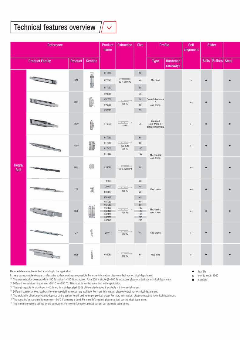
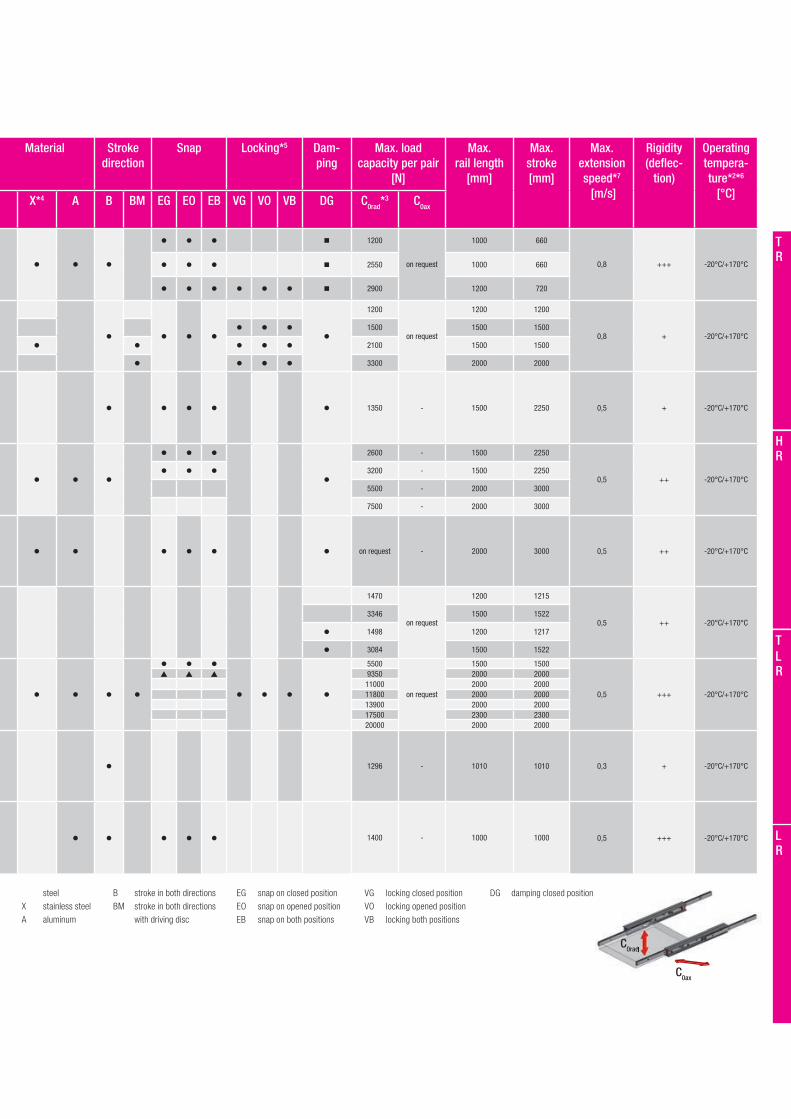
Reported data must be verifi ed according to the application.
In many cases, special designs or alternative surface coatings are possible. For more information, please contact our technical department.
*1 The over extension corresponds to 150 % stroke (1=150 % extraction). For a 200 % stroke (2=200 % extraction) please contact our technical department.
*2 Different temperature ranges from -30 °C to +250 °C, This must be verifi ed according to the application.
*3 The load capacity for aluminum is 40 % and for stainless steel 60 % of the stated values, if available in this material variant.
*4 Different stainless steels, such as the «electropolishing» option, are available. For more information, please contact our technical department.
*5 The availability of locking systems depends on the system length and varies per product group. For more information, please contact our technical department.
*6 The operating temperature is maximum +50°C if damping is used. For more information, please contact our technical department.
*7 The maximum value is defi ned by the application. For more information, please contact our technical department.
feasible
only to length 1000
n standard
Technical features overview
Reference Product name
Extraction Size Profi le Selfalignment
Slider Material Stroke direction
Snap Locking*5 Dam-ping
Max. load capacity per pair
[N]
Max. rail length
[mm]
Max. stroke [mm]
Max. extensionspeed*7
[m/s]
Rigidity(defl ec-
tion)
Operating tempera-ture*2*6
[°C]Product Family Product Section Type Hardened raceways
Balls Rollers Steel X*4 A B BM EG EO EB VG VO VB DG C0rad*3 C0ax
Hegra Rail
HTT
HTT030
60 % to 66 %
30
Machined +
n 1200
on request
1000 660
0,8 +++ -20°C/+170°CHTT040 40 n 2550 1000 660
HTT050 50 n 2900 1200 720
HVC
HVC045
100 %
45
Bended sheetmetal &
cold drawn++
1200
on request
1200 1200
0,8 + -20°C/+170°CHVC050 50 1500 1500 1500
HVC058 58 2100 1500 1500
HVC075 75 3300 2000 2000
H1C*1 H1C075150%
75Machined,
cold drawn &bended sheetmetal
++ 1350 - 1500 2250 0,5 + -20°C/+170°C
H1T*1
H1T060
150 % to200 %
60
Machined &cold drawn
++
2600 - 1500 2250
0,5 ++ -20°C/+170°CH1T080 80 3200 - 1500 2250
H1T100 100 5500 - 2000 3000
H1T150 150 7500 - 2000 3000
H2H H2H080150 % to 200 %
80 ++ on request - 2000 3000 0,5 ++ -20°C/+170°C
LTH
LTH30
100 %
30
Cold drawn ++
1470
on request
1200 1215
0,5 ++ -20°C/+170°CLTH45 45 3346 1500 1522
LTH30S 30 1498 1200 1217
LTH45S 45 3084 1500 1522
HGT
HGT060
100 %
60
Machined &cold drawn
++
5500
on request
1500 1500
0,5 +++ -20°C/+170°C
HGT080 80 9350 2000 2000HGT100 100 11000 2000 2000HGT120 120 11800 2000 2000HGT150 150 13900 2000 2000HGT200 200 17500 2300 2300HGT240 250 20000 2000 2000
LTF LTF44100 %
44 Cold drawn ++ 1296 - 1010 1010 0,3 + -20°C/+170°C
HGS HGS060100 %
60 Machined ++ 1400 - 1000 1000 0,5 +++ -20°C/+170°C
C0ax
C0rad0rad
steel
X stainless steel
A aluminum
B stroke in both directions
BM stroke in both directions
with driving disc
EG snap on closed position
EO snap on opened position
EB snap on both positions
VG locking closed position
VO locking opened position
VB locking both positions
DG damping closed position
Reference Product name
Extraction Size Profi le Selfalignment
Slider Material Stroke direction
Snap Locking*5 Dam-ping
Max. load capacity per pair
[N]
Max. rail length
[mm]
Max. stroke [mm]
Max. extensionspeed*7
[m/s]
Rigidity(defl ec-
tion)
Operating tempera-ture*2*6
[°C]Product Family Product Section Type Hardened raceways
Balls Rollers Steel X*4 A B BM EG EO EB VG VO VB DG C0rad*3 C0ax
TR
HR
LR
TLR
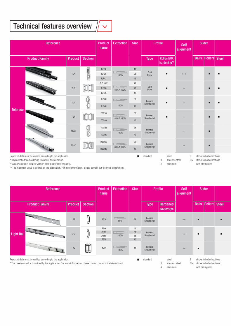
Reported data must be verified according to the application.
*1 High dept nitride hardening treatment and oxidation.
*2 Also available in TLN.HP version with greater load capacity.
*3 The maximum value is defined by the application. For more information, please contact our technical department.
Telerace
TLR
TLR18
100%
18
ColdDraw n +++ n n n n
1304 - 770 770
1,0 ++++ -20 °C/+110 °CTLR28 28 3264 - 1490 1500
TLR43 43 7672 - 1970 1980
TLQ
TLQ18FF
80% A 120%
18
ColdDraw n + n n n n n
946 426 770 770
1,0 +++ -20 °C/+110 °CTLQ28 28 2058 808 1490 1490
TLR43 43 4978 1784 1970 1970
TLN
TLN30
100%
30Formed
Sheetmetal n + n n n n
1776*2 - 1490 1500
1,0 ++++ -20 °C/+80 °C
TLN40 40 3648*2 - 1970 1980
TQN
TQN30
80% A 120%
30Formed
Sheetmetal n + n n n n n
1362 476 1490 1490
1,0 +++ -20 °C/+80 °C
TQN40 40 2592 906 1970 1970
TLAX
TLAX26
100%
26Formed
Sheetmetal+ n n n n
1330 - 1200 1200
1,0 ++++ -20 °C/+80 °C
TLAX40 40 2422 - 1600 1600
TQAX
TQAX26
80% A 120%
26Formed
Sheetmetal+ n n n n n
1008 352 1200 1200
1,0 +++ -20 °C/+80 °C
TQAX40 40 2170 760 1600 1600
steel
X stainless steel
A aluminum
B stroke in both directions
BM stroke in both directions
with driving disc
n standard
Reference Product name
Extraction Size Profile Selfalignment
Slider Material Stroke direction
Suitable for variable stroke
cycles
Suitable for vertical
stroke
Damping closed
position
Max. load capacity per pair
[N]
Max. rail length
[mm]
Max. stroke [mm]
Max. extensionspeed*3
[m/s]
Rigidity(deflection)
Operating temperature
[°C]
Product Family Product Section Type Rollon NOXhardening*1
Balls Rollers Steel X A B BM C0rad C0ax
Reported data must be verified according to the application.
* The maximum value is defined by the application. For more information, please contact our technical department.
Light Rail
LPS LPS3850%
38Formed
Sheetmetal++ n n 350 100 473 373 0,5 + +10 °C/+40 °C
LFS
LFS46
100%
46
Formed Sheetmetal
++ n n
n 400 100 600 610
0,5 + +10 °C/+40 °CLFS57 57 n 800 160 750 800
LFS58 58 n n 600 - 550 584
LFS70 70 n 2000 300 1100 1100
LFX LFX27100%
27Formed
Sheetmetal++ n n 350 50 550 576 0,5 + -30 °C/+200 °C
steel
X stainless steel
A aluminum
B stroke in both directions
BM stroke in both directions
with driving disc
n standard
Reference Product name
Extraction Size Profile Selfalignment
Slider Material Stroke direction
Snapclosed position
Locking Damping closed
position
Max. load capacity per pair
[N]
Max. rail length
[mm]
Max. stroke [mm]
Max. extension
speed* [m/s]
Rigidity(deflec-
tion)
Operating tempera-
ture[°C]Product Family Product Section Type Hardened
racewaysBalls Rollers Steel X A B BM C0rad C0ax
Technical features overview
C0ax0ax
C0radC
Telerace
TLR
TLR18
100%
18
ColdDraw n +++ n n n n
1304 - 770 770
1,0 ++++ -20 °C/+110 °CTLR28 28 3264 - 1490 1500
TLR43 43 7672 - 1970 1980
TLQ
TLQ18FF
80% A 120%
18
ColdDraw n + n n n n n
946 426 770 770
1,0 +++ -20 °C/+110 °CTLQ28 28 2058 808 1490 1490
TLR43 43 4978 1784 1970 1970
TLN
TLN30
100%
30Formed
Sheetmetal n + n n n n
1776*2 - 1490 1500
1,0 ++++ -20 °C/+80 °C
TLN40 40 3648*2 - 1970 1980
TQN
TQN30
80% A 120%
30Formed
Sheetmetal n + n n n n n
1362 476 1490 1490
1,0 +++ -20 °C/+80 °C
TQN40 40 2592 906 1970 1970
TLAX
TLAX26
100%
26Formed
Sheetmetal+ n n n n
1330 - 1200 1200
1,0 ++++ -20 °C/+80 °C
TLAX40 40 2422 - 1600 1600
TQAX
TQAX26
80% A 120%
26Formed
Sheetmetal+ n n n n n
1008 352 1200 1200
1,0 +++ -20 °C/+80 °C
TQAX40 40 2170 760 1600 1600
Reference Product name
Extraction Size Profi le Selfalignment
Slider Material Stroke direction
Suitable for variable stroke
cycles
Suitable for vertical
stroke
Damping closed
position
Max. load capacity per pair
[N]
Max. rail length
[mm]
Max. stroke [mm]
Max. extensionspeed*3
[m/s]
Rigidity(defl ection)
Operating temperature
[°C]
Product Family Product Section Type Rollon NOXhardening*1
Balls Rollers Steel X A B BM C0rad C0ax
Light Rail
LPS LPS3850%
38Formed
Sheetmetal++ n n 350 100 473 373 0,5 + +10 °C/+40 °C
LFS
LFS46
100%
46
Formed Sheetmetal
++ n n
n 400 100 600 610
0,5 + +10 °C/+40 °CLFS57 57 n 800 160 750 800
LFS58 58 n n 600 - 550 584
LFS70 70 n 2000 300 1100 1100
LFX LFX27100%
27Formed
Sheetmetal++ n n 350 50 550 576 0,5 + -30 °C/+200 °C
Reference Product name
Extraction Size Profi le Selfalignment
Slider Material Stroke direction
Snapclosed position
Locking Damping closed
position
Max. load capacity per pair
[N]
Max. rail length
[mm]
Max. stroke [mm]
Max. extension
speed* [m/s]
Rigidity(defl ec-
tion)
Operating tempera-
ture[°C]Product Family Product Section Type Hardened
racewaysBalls Rollers Steel X A B BM C0rad C0ax
C0ax
C0rad0rad
TR
HR
LR
TLR

Telescopic Rail
FrontespizioTelescopicrail.indd 1 28/09/2018 13:21:09
TR-2
Product explanation
1 Product explanation
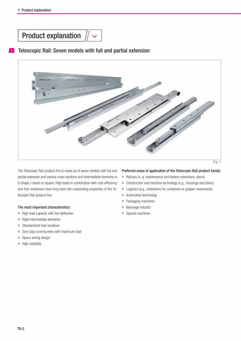
Telescopic Rail: Seven models with full and partial extension
Preferred areas of application of the Telescopic Rail product family:
■ Railcars (e. g. maintenance and battery extensions, doors)
■ Construction and machine technology (e.g., housings and doors)
■ Logistics (e.g., extensions for containers or gripper movements)
■ Automotive technology
■ Packaging machines
■ Beverage industry
■ Special machines
The Telescopic Rail product line is made up of seven models with full and
partial extension and various cross-sections and intermediate elements in
S-shape, I-beam or square. High loads in combination with cost-efficiency
and free movement have long been the outstanding properties of the Te-
lescopic Rail product line.
The most important characteristics:
■ High load capacity with low deflection
■ Rigid intermediate elements
■ Standardized hole locations
■ Zero-play running even with maximum load
■ Space saving design
■ High reliability
Fig. 1
TR-3
Telescopic Rail
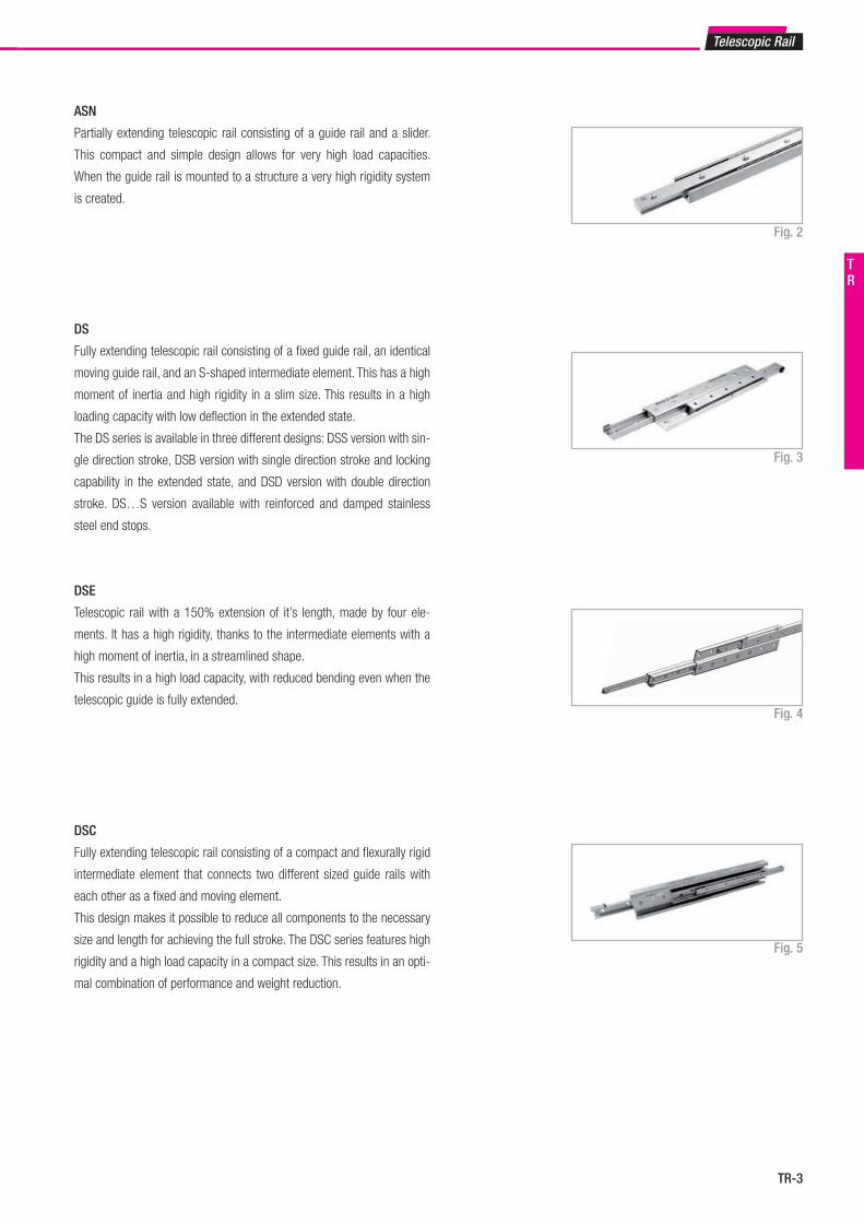
DSE
Telescopic rail with a 150% extension of it’s length, made by four ele-
ments. It has a high rigidity, thanks to the intermediate elements with a
high moment of inertia, in a streamlined shape.
This results in a high load capacity, with reduced bending even when the
telescopic guide is fully extended.Fig. 4
ASN
Partially extending telescopic rail consisting of a guide rail and a slider.
This compact and simple design allows for very high load capacities.
When the guide rail is mounted to a structure a very high rigidity system
is created.
Fig. 2
Fig. 3
Fig. 5
DSC
Fully extending telescopic rail consisting of a compact and flexurally rigid
intermediate element that connects two different sized guide rails with
each other as a fixed and moving element.
This design makes it possible to reduce all components to the necessary
size and length for achieving the full stroke. The DSC series features high
rigidity and a high load capacity in a compact size. This results in an opti-
mal combination of performance and weight reduction.
DS
Fully extending telescopic rail consisting of a fixed guide rail, an identical
moving guide rail, and an S-shaped intermediate element. This has a high
moment of inertia and high rigidity in a slim size. This results in a high
loading capacity with low deflection in the extended state.
The DS series is available in three different designs: DSS version with sin-
gle direction stroke, DSB version with single direction stroke and locking
capability in the extended state, and DSD version with double direction
stroke. DS…S version available with reinforced and damped stainless
steel end stops.
TR
TR-4
1 Product explanation
Fig. 7
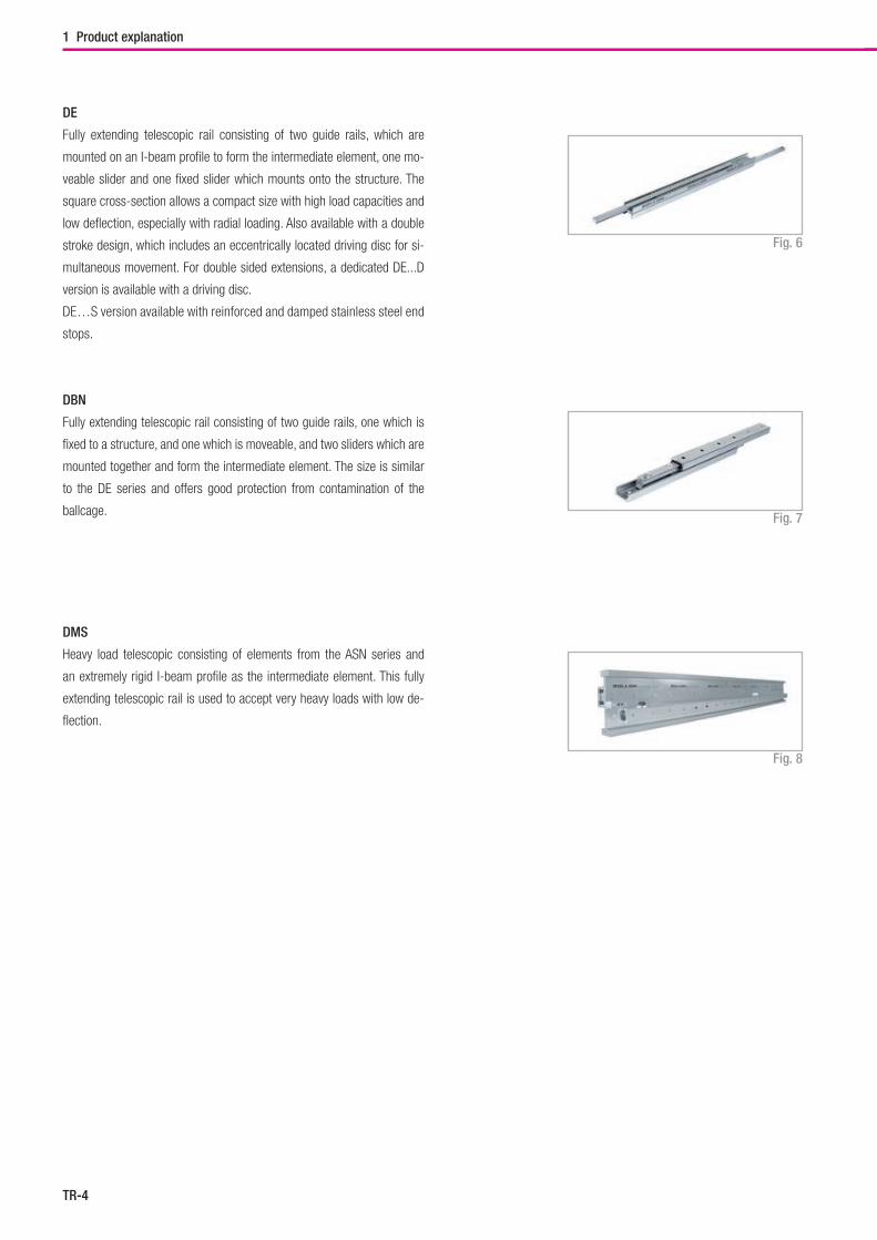
DMS
Heavy load telescopic consisting of elements from the ASN series and
an extremely rigid I-beam profile as the intermediate element. This fully
extending telescopic rail is used to accept very heavy loads with low de-
flection.
Fig. 8
DBN
Fully extending telescopic rail consisting of two guide rails, one which is
fixed to a structure, and one which is moveable, and two sliders which are
mounted together and form the intermediate element. The size is similar
to the DE series and offers good protection from contamination of the
ballcage.
DE
Fully extending telescopic rail consisting of two guide rails, which are
mounted on an I-beam profile to form the intermediate element, one mo-
veable slider and one fixed slider which mounts onto the structure. The
square cross-section allows a compact size with high load capacities and
low deflection, especially with radial loading. Also available with a double
stroke design, which includes an eccentrically located driving disc for si-
multaneous movement. For double sided extensions, a dedicated DE...D
version is available with a driving disc.
DE…S version available with reinforced and damped stainless steel end
stops.
Fig. 6
TR-5
Telescopic Rail
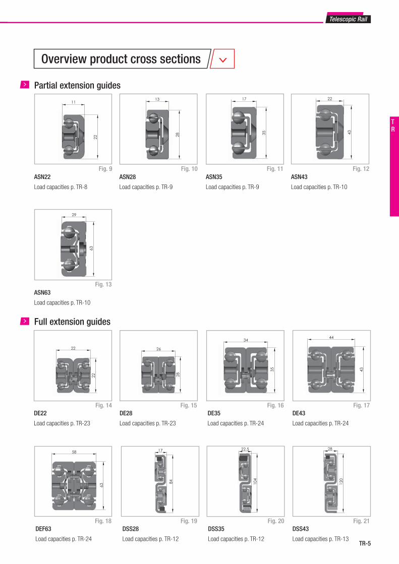
Overview product cross sections
ASN22
Load capacities p. TR-8
Fig. 9
Partial extension guides
Fig. 11 Fig. 12
Fig. 13
ASN28
Load capacities p. TR-9
ASN35
Load capacities p. TR-9
ASN43
Load capacities p. TR-10
ASN63
Load capacities p. TR-10
Fig. 10
DE35
Load capacities p. TR-24
Fig. 14
Full extension guides
Fig. 16
Fig. 18 Fig. 19
DE22
Load capacities p. TR-23
DEF63
Load capacities p. TR-24
DSS28
Load capacities p. TR-12
Fig. 20 Fig. 21DSS35
Load capacities p. TR-12
DSS43
Load capacities p. TR-13
Fig. 17DE43
Load capacities p. TR-24
Fig. 15DE28
Load capacities p. TR-23
11
29
13 17 2222
63
28 35 43
22 28
22 26
35
34
43
44
63
58 17 22,5
84 104
120
28
TR
TR-6
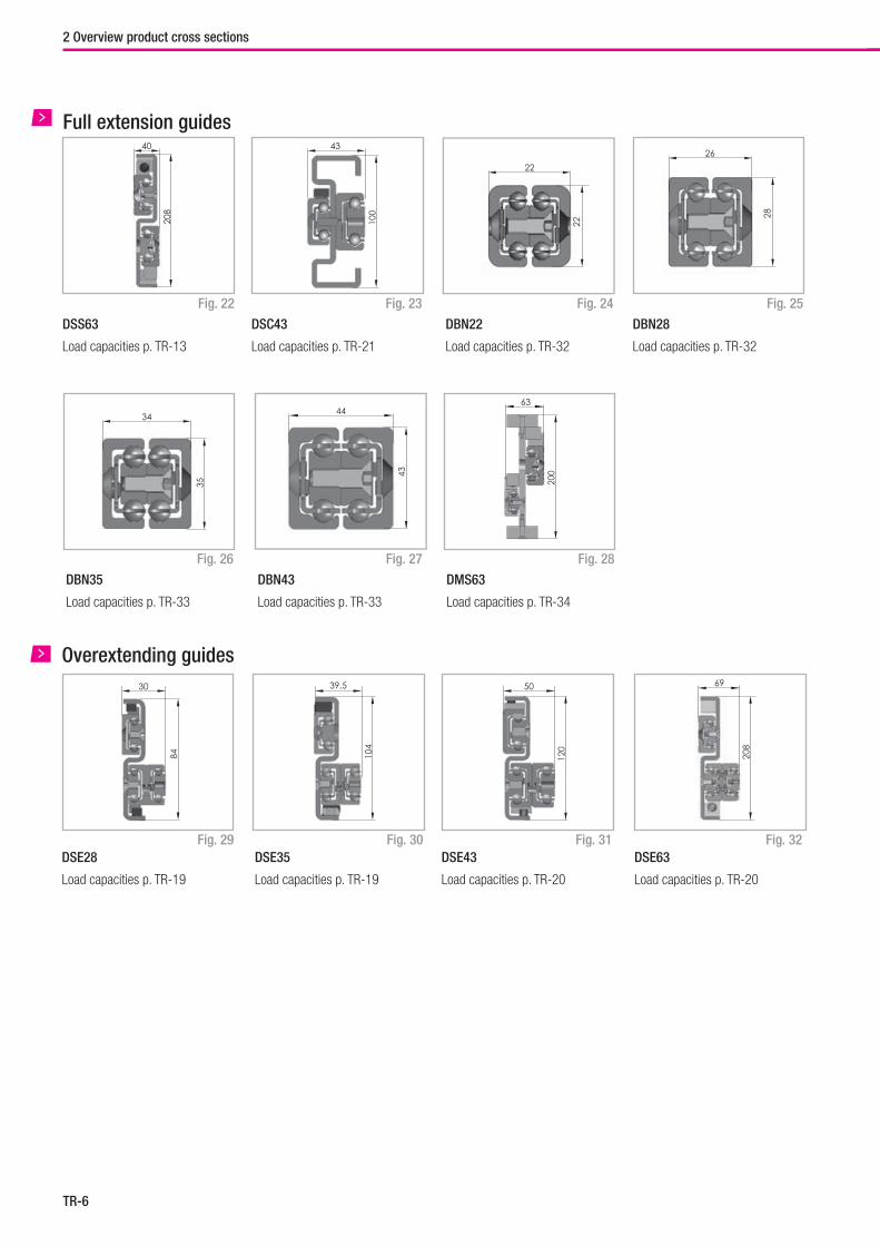
DBN22
Load capacities p. TR-32
Fig. 22
Full extension guides
Fig. 24
Fig. 26 Fig. 27
DSS63
Load capacities p. TR-13
DBN35
Load capacities p. TR-33
DBN43
Load capacities p. TR-33
Fig. 28
DMS63
Load capacities p. TR-34
Fig. 25
DBN28
Load capacities p. TR-32
Fig. 23
DSC43
Load capacities p. TR-21
DSE35
Load capacities p. TR-19
Fig. 29
Overextending guides
Fig. 30 Fig. 31 Fig. 32DSE28
Load capacities p. TR-19
DSE43
Load capacities p. TR-20
DSE63
Load capacities p. TR-20
2 Overview product cross sections
208
100
22
28
40 43
2226
35
43
200
34 4463
84 104
120
208
30 39,5 50 69
TR-7
Technical data
Telescopic Rail
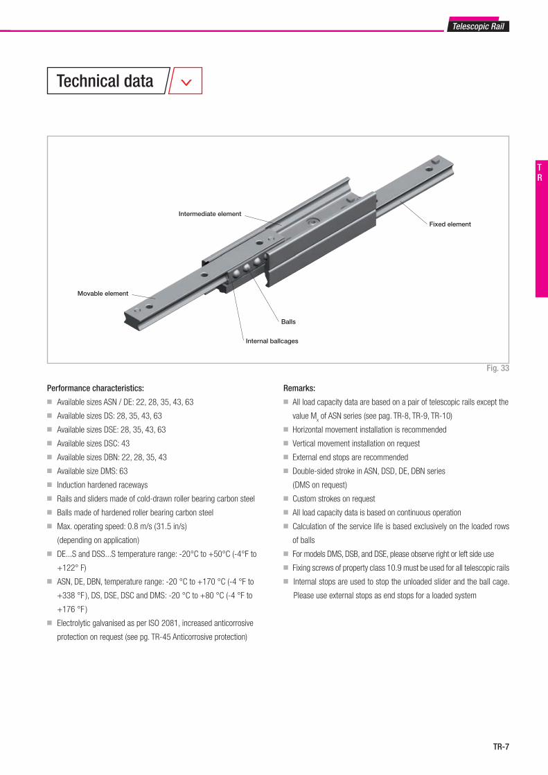
Remarks:
■ All load capacity data are based on a pair of telescopic rails except the
value Mx of ASN series (see pag. TR-8, TR-9, TR-10)
■ Horizontal movement installation is recommended
■ Vertical movement installation on request
■ External end stops are recommended
■ Double-sided stroke in ASN, DSD, DE, DBN series
( DMS on request )
■ Custom strokes on request
■ All load capacity data is based on continuous operation
■ Calculation of the service life is based exclusively on the loaded rows
of balls
■ For models DMS, DSB, and DSE, please observe right or left side use
■ Fixing screws of property class 10.9 must be used for all telescopic rails
■ Internal stops are used to stop the unloaded slider and the ball cage.
Please use external stops as end stops for a loaded system
Performance characteristics:
■ Available sizes ASN / DE: 22, 28, 35, 43, 63
■ Available sizes DS: 28, 35, 43, 63
■ Available sizes DSE: 28, 35, 43, 63
■ Available sizes DSC: 43
■ Available sizes DBN: 22, 28, 35, 43
■ Available size DMS: 63
■ Induction hardened raceways
■ Rails and sliders made of cold-drawn roller bearing carbon steel
■ Balls made of hardened roller bearing carbon steel
■ Max. operating speed: 0.8 m/s ( 31.5 in/s )
( depending on application )
■ DE...S and DSS...S temperature range: -20°C to +50°C (-4°F to
+122° F)
■ ASN, DE, DBN, temperature range: -20 °C to +170 °C (-4 °F to
+338 °F ), DS, DSE, DSC and DMS: -20 °C to +80 °C (-4 °F to
+176 °F )
■ Electrolytic galvanised as per ISO 2081, increased anticorrosive
protection on request (see pg. TR-45 Anticorrosive protection)
Fig. 33
Internal ballcages
Balls
Movable element
Intermediate element
Fixed element
TR
TR-8
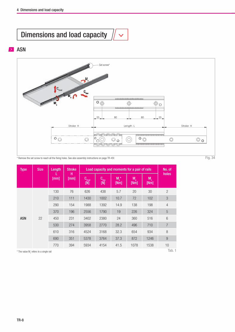
Type Size Length L
[mm]
StrokeH
[mm]
Load capacity and moments for a pair of rails No. ofholes
C0rad
[N]C0ax
[N]Mx*
[Nm]My
[Nm]Mz
[Nm]
ASN 22
130 76 626 438 5.7 20 30 2
210 111 1430 1002 10.7 72 102 3
290 154 1988 1392 14.9 138 198 4
370 196 2556 1790 19 226 324 5
450 231 3402 2380 24 360 516 6
530 274 3958 2770 28.2 496 710 7
610 316 4524 3168 32.3 654 934 8
690 351 5378 3764 37.3 872 1246 9
770 394 5934 4154 41.5 1078 1538 10
Dimensions and load capacity
* The value Mx refers to a single rail
Set screw*
C0ax
Mz
My
Mx
C0ax
Mz
Mx
My
C0radCC
ASN
Fig. 34* Remove the set screw to reach all the fi xing holes. See also assembly instructions on page TR-45f.
Tab. 1
4 Dimensions and load capacity
Length LStroke H Stroke H
25 80 80 25
TR-9
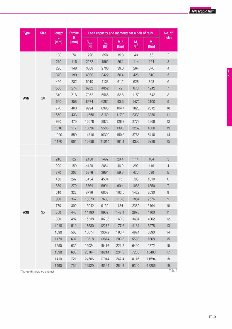
Type Size Length L
[mm]
StrokeH
[mm]
Load capacity and moments for a pair of rails No. ofholes
C0rad
[N]C0ax
[N]Mx *[Nm]
My
[Nm]Mz
[Nm]
ASN 28
130 74 1226 858 15.3 40 56 2
210 116 2232 1562 26.1 114 164 3
290 148 3868 2708 39.6 264 376 4
370 190 4890 3422 50.4 426 610 5
450 232 5910 4138 61.2 628 898 6
530 274 6932 4852 72 870 1242 7
610 316 7952 5566 82.8 1150 1642 8
690 358 8974 6282 93.6 1470 2100 9
770 400 9994 6996 104.4 1828 2612 10
850 433 11656 8160 117.9 2330 3330 11
930 475 12676 8872 128.7 2778 3968 12
1010 517 13696 9586 139.5 3262 4660 13
1090 559 14716 10300 150.3 3788 5410 14
1170 601 15736 11014 161.1 4350 6216 15
ASN 35
210 127 2130 1492 29.4 114 164 3
290 159 4120 2884 46.9 292 416 4
370 203 5276 3694 59.9 476 680 5
450 247 6434 4504 73 708 1010 6
530 279 8564 5994 90.4 1086 1550 7
610 323 9716 6802 103.5 1422 2030 8
690 367 10870 7608 116.6 1804 2576 9
770 399 13042 9130 134 2382 3404 10
850 443 14190 9932 147.1 2870 4100 11
930 487 15338 10736 160.2 3404 4862 12
1010 519 17530 12272 177.6 4184 5978 13
1090 563 18674 13072 190.7 4824 6890 14
1170 607 19818 13874 203.8 5508 7868 15
1250 639 22024 15416 221.2 6490 9272 16
1330 683 23164 16214 234.3 7280 10400 17
1410 727 24306 17014 247.4 8116 11594 18
1490 759 26520 18564 264.8 9300 13286 19
* The value Mx refers to a single rail
Telescopic Rail
Tab. 2
TR
TR-10
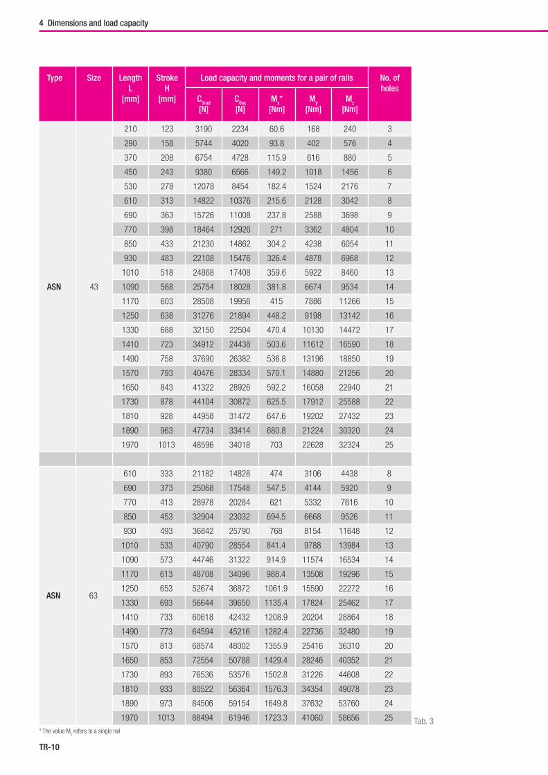
Type Size Length L
[mm]
StrokeH
[mm]
Load capacity and moments for a pair of rails No. ofholes
C0rad
[N]C0ax
[N]Mx*
[Nm]My
[Nm]Mz
[Nm]
ASN 43
210 123 3190 2234 60.6 168 240 3
290 158 5744 4020 93.8 402 576 4
370 208 6754 4728 115.9 616 880 5
450 243 9380 6566 149.2 1018 1456 6
530 278 12078 8454 182.4 1524 2176 7
610 313 14822 10376 215.6 2128 3042 8
690 363 15726 11008 237.8 2588 3698 9
770 398 18464 12926 271 3362 4804 10
850 433 21230 14862 304.2 4238 6054 11
930 483 22108 15476 326.4 4878 6968 12
1010 518 24868 17408 359.6 5922 8460 13
1090 568 25754 18028 381.8 6674 9534 14
1170 603 28508 19956 415 7886 11266 15
1250 638 31276 21894 448.2 9198 13142 16
1330 688 32150 22504 470.4 10130 14472 17
1410 723 34912 24438 503.6 11612 16590 18
1490 758 37690 26382 536.8 13196 18850 19
1570 793 40476 28334 570.1 14880 21256 20
1650 843 41322 28926 592.2 16058 22940 21
1730 878 44104 30872 625.5 17912 25588 22
1810 928 44958 31472 647.6 19202 27432 23
1890 963 47734 33414 680.8 21224 30320 24
1970 1013 48596 34018 703 22628 32324 25
ASN 63
610 333 21182 14828 474 3106 4438 8
690 373 25068 17548 547.5 4144 5920 9
770 413 28978 20284 621 5332 7616 10
850 453 32904 23032 694.5 6668 9526 11
930 493 36842 25790 768 8154 11648 12
1010 533 40790 28554 841.4 9788 13984 13
1090 573 44746 31322 914.9 11574 16534 14
1170 613 48708 34096 988.4 13508 19296 15
1250 653 52674 36872 1061.9 15590 22272 16
1330 693 56644 39650 1135.4 17824 25462 17
1410 733 60618 42432 1208.9 20204 28864 18
1490 773 64594 45216 1282.4 22736 32480 19
1570 813 68574 48002 1355.9 25416 36310 20
1650 853 72554 50788 1429.4 28246 40352 21
1730 893 76536 53576 1502.8 31226 44608 22
1810 933 80522 56364 1576.3 34354 49078 23
1890 973 84506 59154 1649.8 37632 53760 24
1970 1013 88494 61946 1723.3 41060 58656 25
* The value Mx refers to a single rail
Tab. 3
4 Dimensions and load capacity
TR-11
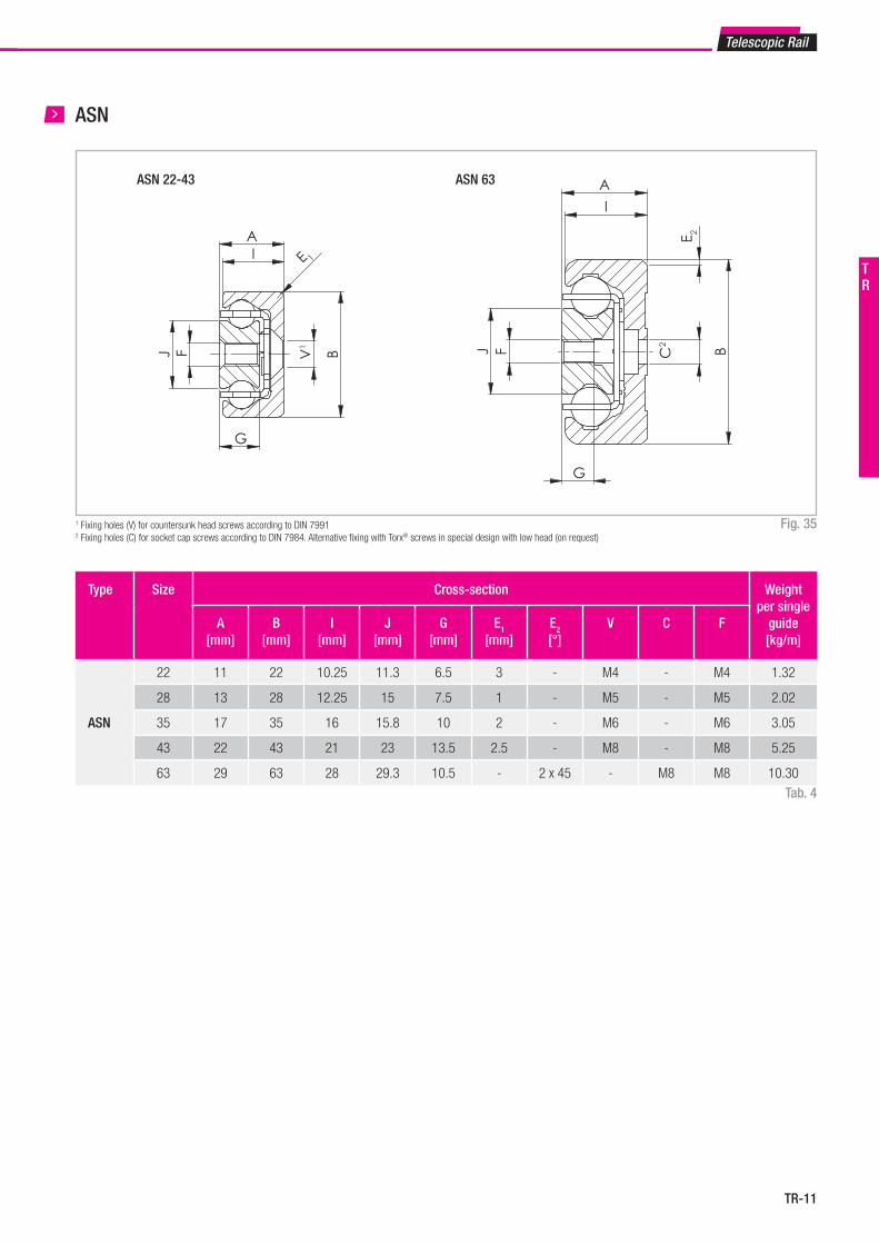
Type Size Cross-section Weight per single
guide[kg/m]
A[mm]
B[mm]
I[mm]
J[mm]
G[mm]
E1
[mm]E2
[°]V C F
ASN
22 11 22 10.25 11.3 6.5 3 - M4 - M4 1.32
28 13 28 12.25 15 7.5 1 - M5 - M5 2.02
35 17 35 16 15.8 10 2 - M6 - M6 3.05
43 22 43 21 23 13.5 2.5 - M8 - M8 5.25
63 29 63 28 29.3 10.5 - 2 x 45 - M8 M8 10.30
ASN 22-43 ASN 63
ABV
1
I E 1
G
J F
I
A
BC2
GJ
E 2
F
A
BV1
I E 1
G
J F
I
A
BC2
G
J
E 2
F
Telescopic Rail
ASN
1 Fixing holes (V) for countersunk head screws according to DIN 79912 Fixing holes (C) for socket cap screws according to DIN 7984. Alternative fixing with Torx® screws in special design with low head (on request)
Fig. 35
Tab. 4
TR
TR-12
C0radC0rad
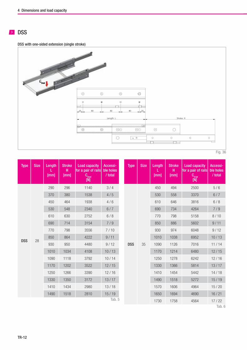
Fig. 36
DSS with one-sided extension (single stroke)
DSS
Type Size Length L
[mm]
StrokeH
[mm]
Load capacity for a pair of rails
C0rad
[N]
Accessi-ble holes
/ total
DSS 28
290 296 1140 3 / 4
370 380 1538 4 / 5
450 464 1938 4 / 6
530 548 2340 6 / 7
610 630 2752 6 / 8
690 714 3154 7 / 9
770 798 3556 7 / 10
850 864 4222 9 / 11
930 950 4480 9 / 12
1010 1034 4108 10 / 13
1090 1118 3792 10 / 14
1170 1202 3522 12 / 15
1250 1266 3390 12 / 16
1330 1350 3172 13 / 17
1410 1434 2980 13 / 18
1490 1518 2810 15 / 19
Type Size Length L
[mm]
StrokeH
[mm]
Load capacity for a pair of rails
C0rad
[N]
Accessi-ble holes
/ total
DSS 35
450 494 2500 5 / 6
530 558 3370 6 / 7
610 646 3816 6 / 8
690 734 4264 7 / 9
770 798 5158 8 / 10
850 886 5602 9 / 11
930 974 6048 9 / 12
1010 1038 6952 10 / 13
1090 1126 7016 11 / 14
1170 1214 6480 12 / 15
1250 1278 6242 12 / 16
1330 1366 5814 13 / 17
1410 1454 5442 14 / 18
1490 1518 5272 15 / 19
1570 1606 4964 15 / 20
1650 1694 4690 16 / 21
1730 1758 4564 17 / 22Tab. 6
Tab. 5
4 Dimensions and load capacity
Stroke H
25 80 80 80 25
Length L
TR-13
Telescopic Rail
Type Size Length L
[mm]
StrokeH
[mm]
Load capacity for a pair of rails
C0rad
[N]
Accessi-ble holes
/ total
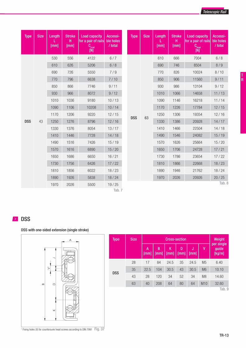
DSS 43
530 556 4122 6 / 7
610 626 5206 6 / 8
690 726 5550 7 / 9
770 796 6638 7 / 10
850 866 7746 9 / 11
930 966 8072 9 / 12
1010 1036 9180 10 / 13
1090 1106 10208 10 / 14
1170 1206 9220 12 / 15
1250 1276 8796 12 / 16
1330 1376 8054 13 / 17
1410 1446 7728 14 / 18
1490 1516 7426 15 / 19
1570 1616 6890 15 / 20
1650 1686 6650 16 / 21
1730 1756 6426 17 / 22
1810 1856 6022 18 / 23
1890 1926 5838 18 / 24
1970 2026 5500 19 / 25
Tab. 7
Type Size Length L
[mm]
StrokeH
[mm]
Load capacity for a pair of rails
C0rad
[N]
Accessi-ble holes
/ total
DSS 63
610 666 7004 6 / 8
690 746 8504 8 / 9
770 826 10024 8 / 10
850 906 11560 9 / 11
930 986 13104 9 / 12
1010 1066 14658 11 / 13
1090 1146 16218 11 / 14
1170 1226 17784 12 / 15
1250 1306 19354 12 / 16
1330 1386 20928 14 / 17
1410 1466 22504 14 / 18
1490 1546 24082 15 / 19
1570 1626 25664 15 / 20
1650 1706 24728 17 / 21
1730 1786 23654 17 / 22
1810 1866 22668 18 / 23
1890 1946 21762 18 / 24
1970 2026 20926 20 / 25Tab. 8
A
B D
V1
JK
DSS
DSS with one-sided extension (single stroke)
1 Fixing holes (V) for countersunk head screws according to DIN 7991 Fig. 37
Type Size Cross-section Weight per single
guide[kg/m]
A[mm]
B[mm]
K[mm]
D[mm]
J[mm]
V
DSS
28 17 84 24.5 35 24.5 M5 6.40
35 22.5 104 30.5 43 30.5 M6 10.10
43 28 120 34 52 34 M8 14.60
63 40 208 64 80 64 M10 32.60Tab. 9
TR
TR-14
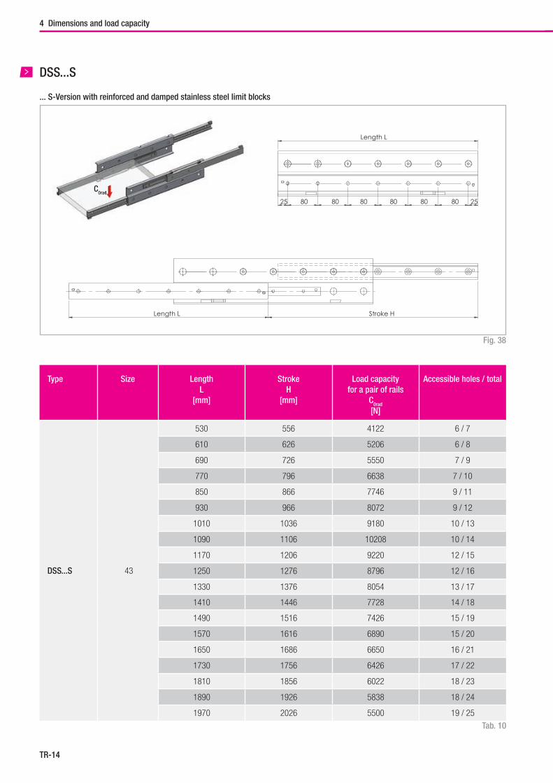
Fig. 38
... S-Version with reinforced and damped stainless steel limit blocks
DSS...S
Type Size Length L
[mm]
StrokeH
[mm]
Load capacity for a pair of rails
C0rad
[N]
Accessible holes / total
DSS...S 43
530 556 4122 6 / 7
610 626 5206 6 / 8
690 726 5550 7 / 9
770 796 6638 7 / 10
850 866 7746 9 / 11
930 966 8072 9 / 12
1010 1036 9180 10 / 13
1090 1106 10208 10 / 14
1170 1206 9220 12 / 15
1250 1276 8796 12 / 16
1330 1376 8054 13 / 17
1410 1446 7728 14 / 18
1490 1516 7426 15 / 19
1570 1616 6890 15 / 20
1650 1686 6650 16 / 21
1730 1756 6426 17 / 22
1810 1856 6022 18 / 23
1890 1926 5838 18 / 24
1970 2026 5500 19 / 25
Tab. 10
Stroke HLength L
25 25 80 80 80 80 80 80
Length L
A
B
K
D
J
V¹
4 Dimensions and load capacity
C0rad0rad
TR-15
Telescopic Rail
DSS...S
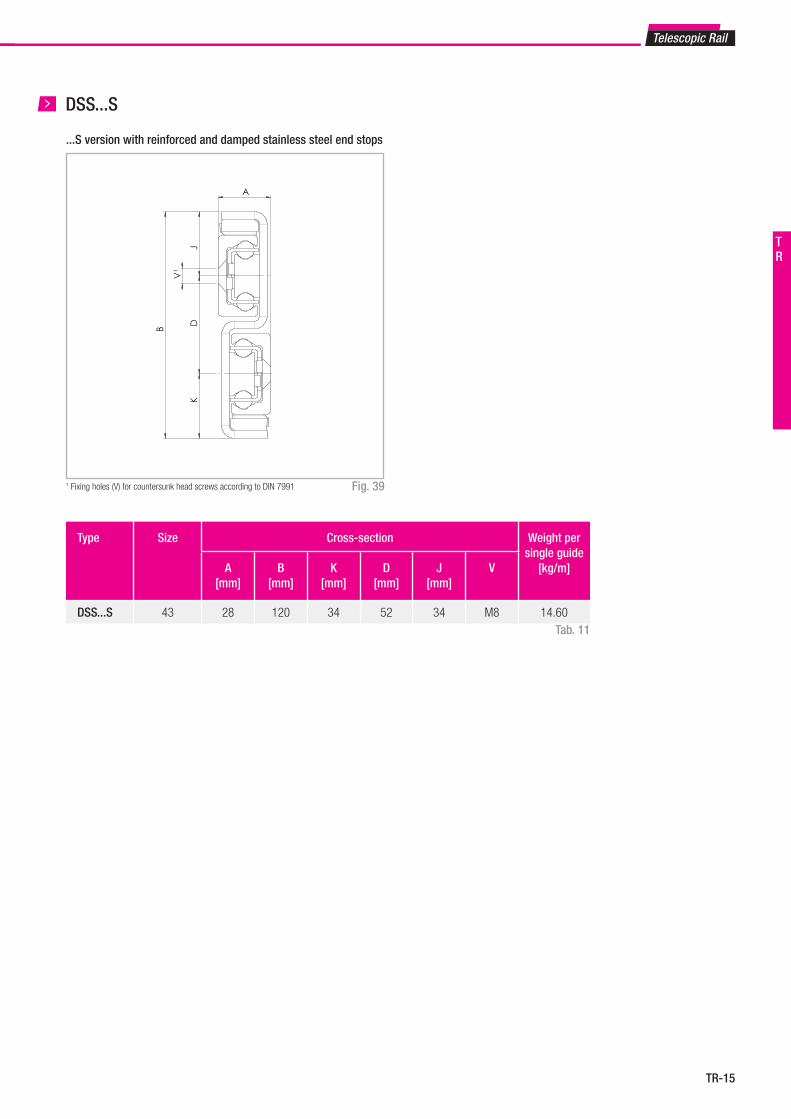
...S version with reinforced and damped stainless steel end stops
1 Fixing holes (V) for countersunk head screws according to DIN 7991 Fig. 39
Type Size Cross-section Weight per single guide
[kg/m]A[mm]
B[mm]
K[mm]
D[mm]
J[mm]
V
DSS...S 43 28 120 34 52 34 M8 14.60Tab. 11
Stroke HLength L
25 25 80 80 80 80 80 80
Length L
A
B
K
D
J
V¹
TR
TR-16
Fmaxin closed position
Type Size L[mm]
Total length[mm]
C[mm]
E[mm]
Fmax*2
[N]Weight per single
guide [kg/m]
DSB
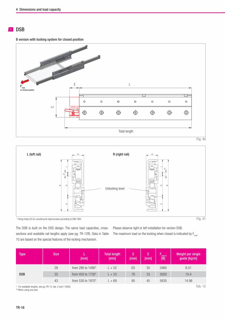
28 from 290 to 1490* L + 52 63 35 2460 6.51
35 from 450 to 1730* L + 53 78 33 3000 10.4
43 from 530 to 1970* L + 69 95 45 5630 14.98
L (left rail) R (right rail)
The DSB is built on the DSS design. The same load capacities, cross-
sections and available rail lengths apply (see pg. TR-12ff). Data in Table
10 are based on the special features of the locking mechanism.
Total length
L
C
E
Unlocking lever
A
B DV
1
JK
A
BD
V1
JK
A
B DV
1
JK
A
BD
V1
JK
4 Dimensions and load capacity
Tab. 12* For available lengths, see pg. TR-12, tab. 5 and 7 (DSS)*² When using one lock
Please observe right or left installation for version DSB.
The maximum load on the locking when closed is indicated by Fmax
.
1 Fixing holes (V) for countersunk head screws according to DIN 7991 Fig. 41
Fig. 40
B version with locking system for closed position
DSB
TR-17
C0radC0rad
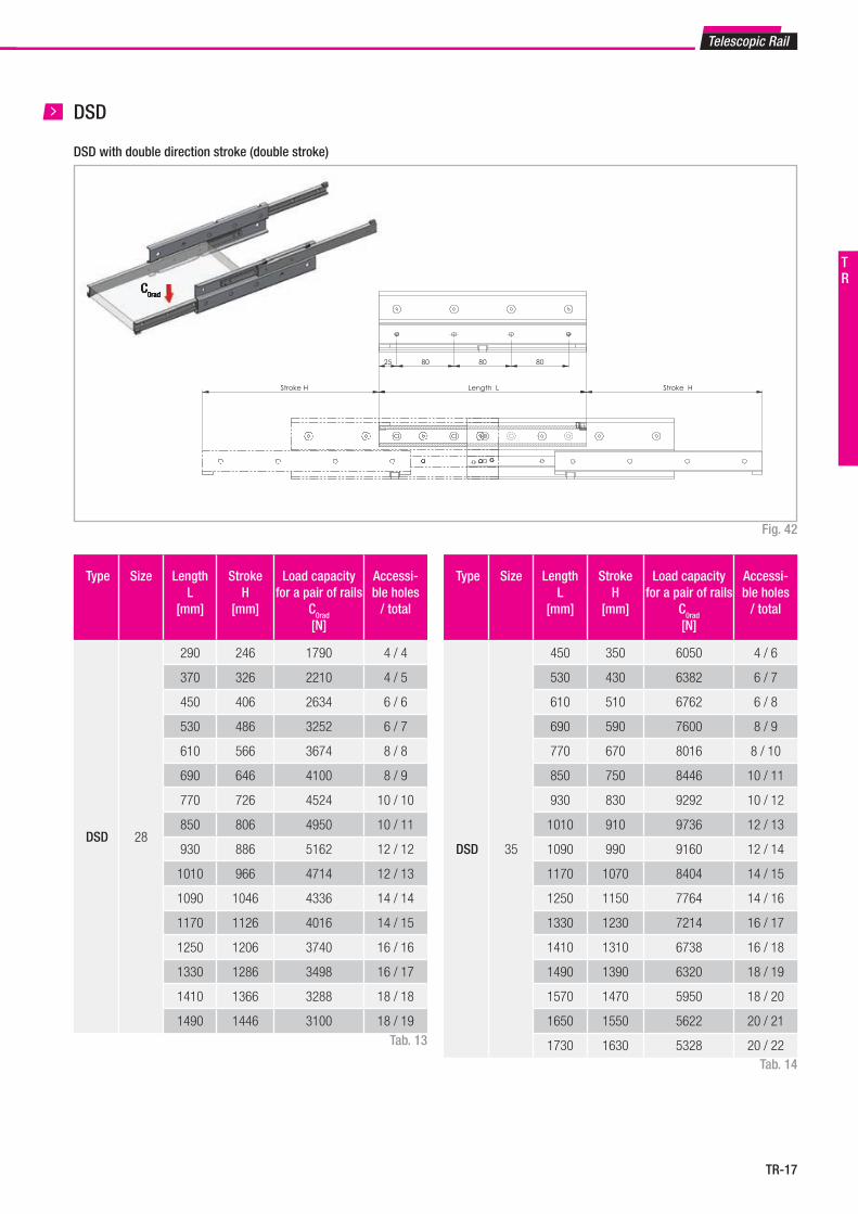
DSD with double direction stroke (double stroke)
Fig. 42
Tab. 13
Type Size Length L
[mm]
StrokeH
[mm]
Load capacity for a pair of rails
C0rad
[N]
Accessi-ble holes
/ total
DSD 28
290 246 1790 4 / 4
370 326 2210 4 / 5
450 406 2634 6 / 6
530 486 3252 6 / 7
610 566 3674 8 / 8
690 646 4100 8 / 9
770 726 4524 10 / 10
850 806 4950 10 / 11
930 886 5162 12 / 12
1010 966 4714 12 / 13
1090 1046 4336 14 / 14
1170 1126 4016 14 / 15
1250 1206 3740 16 / 16
1330 1286 3498 16 / 17
1410 1366 3288 18 / 18
1490 1446 3100 18 / 19
Tab. 14
DSD
Type Size Length L
[mm]
StrokeH
[mm]
Load capacity for a pair of rails
C0rad
[N]
Accessi-ble holes
/ total
DSD 35
450 350 6050 4 / 6
530 430 6382 6 / 7
610 510 6762 6 / 8
690 590 7600 8 / 9
770 670 8016 8 / 10
850 750 8446 10 / 11
930 830 9292 10 / 12
1010 910 9736 12 / 13
1090 990 9160 12 / 14
1170 1070 8404 14 / 15
1250 1150 7764 14 / 16
1330 1230 7214 16 / 17
1410 1310 6738 16 / 18
1490 1390 6320 18 / 19
1570 1470 5950 18 / 20
1650 1550 5622 20 / 21
1730 1630 5328 20 / 22
Stroke HStroke H
25 80 80 80
Length L
Telescopic Rail
TR
TR-18
4 Dimensions and load capacity
A
B D
V1
JK
DSD
Type Size Length L
[mm]
StrokeH
[mm]
Load capacity for a pair of rails
C0rad
[N]
Accessi-ble holes
/ total
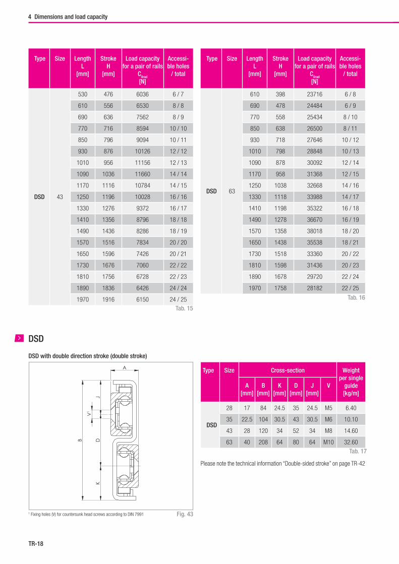
DSD 43
530 476 6036 6 / 7
610 556 6530 8 / 8
690 636 7562 8 / 9
770 716 8594 10 / 10
850 796 9094 10 / 11
930 876 10126 12 / 12
1010 956 11156 12 / 13
1090 1036 11660 14 / 14
1170 1116 10784 14 / 15
1250 1196 10028 16 / 16
1330 1276 9372 16 / 17
1410 1356 8796 18 / 18
1490 1436 8286 18 / 19
1570 1516 7834 20 / 20
1650 1596 7426 20 / 21
1730 1676 7060 22 / 22
1810 1756 6728 22 / 23
1890 1836 6426 24 / 24
1970 1916 6150 24 / 25 Tab. 16
Type Size Length L
[mm]
StrokeH
[mm]
Load capacity for a pair of rails
C0rad
[N]
Accessi-ble holes
/ total
DSD 63
610 398 23716 6 / 8
690 478 24484 6 / 9
770 558 25434 8 / 10
850 638 26500 8 / 11
930 718 27646 10 / 12
1010 798 28848 10 / 13
1090 878 30092 12 / 14
1170 958 31368 12 / 15
1250 1038 32668 14 / 16
1330 1118 33988 14 / 17
1410 1198 35322 16 / 18
1490 1278 36670 16 / 19
1570 1358 38018 18 / 20
1650 1438 35538 18 / 21
1730 1518 33360 20 / 22
1810 1598 31436 20 / 23
1890 1678 29720 22 / 24
1970 1758 28182 22 / 25
Tab. 15
Type Size Cross-section Weight per single
guide[kg/m]
A[mm]
B[mm]
K[mm]
D[mm]
J[mm]
V
DSD
28 17 84 24.5 35 24.5 M5 6.40
35 22.5 104 30.5 43 30.5 M6 10.10
43 28 120 34 52 34 M8 14.60
63 40 208 64 80 64 M10 32.60
Tab. 17
Fig. 431 Fixing holes (V) for countersunk head screws according to DIN 7991
DSD with double direction stroke (double stroke)
Please note the technical information “Double-sided stroke” on page TR-42
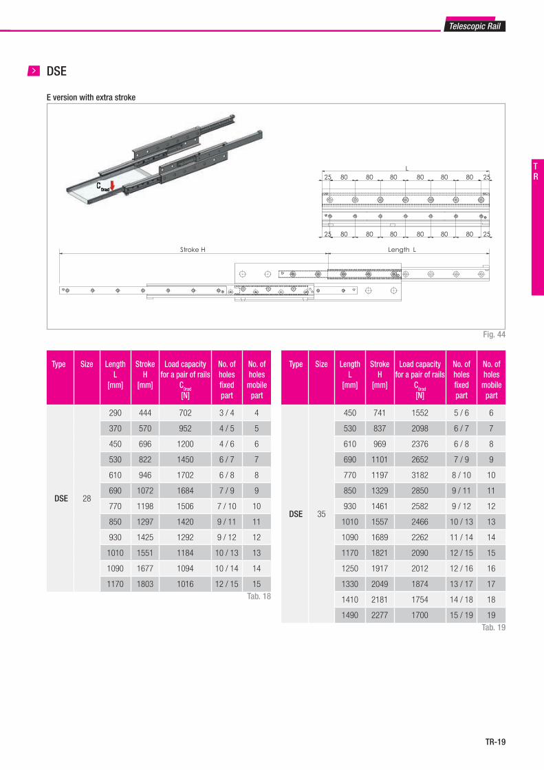
TR-19
C0radC0rad
Telescopic Rail
E version with extra stroke
Fig. 44
Tab. 18
Type Size Length L
[mm]
StrokeH
[mm]
Load capacity for a pair of rails
C0rad
[N]
No. of holesfi xed part
No. of holes
mobile part
DSE 28
290 444 702 3 / 4 4
370 570 952 4 / 5 5
450 696 1200 4 / 6 6
530 822 1450 6 / 7 7
610 946 1702 6 / 8 8
690 1072 1684 7 / 9 9
770 1198 1506 7 / 10 10
850 1297 1420 9 / 11 11
930 1425 1292 9 / 12 12
1010 1551 1184 10 / 13 13
1090 1677 1094 10 / 14 14
1170 1803 1016 12 / 15 15
Type Size Length L
[mm]
StrokeH
[mm]
Load capacity for a pair of rails
C0rad
[N]
No. of holesfi xed part
No. of holes
mobile part
DSE 35
450 741 1552 5 / 6 6
530 837 2098 6 / 7 7
610 969 2376 6 / 8 8
690 1101 2652 7 / 9 9
770 1197 3182 8 / 10 10
850 1329 2850 9 / 11 11
930 1461 2582 9 / 12 12
1010 1557 2466 10 / 13 13
1090 1689 2262 11 / 14 14
1170 1821 2090 12 / 15 15
1250 1917 2012 12 / 16 16
1330 2049 1874 13 / 17 17
1410 2181 1754 14 / 18 18
1490 2277 1700 15 / 19 19
DSE
Tab. 19
Length L
L
Stroke H
25 2580 80 80 80 80 80
25 2580 80 80 80 80 80
TR
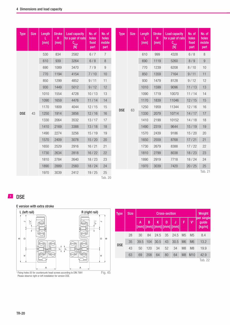
TR-20
Type Size Length L
[mm]
StrokeH
[mm]
Load capacity for a pair of rails
C0rad
[N]
No. of holesfixed part
No. of holes
mobile part
DSE 43
530 834 2582 6 / 7 7
610 939 3264 6 / 8 8
690 1089 3470 7 / 9 9
770 1194 4154 7 / 10 10
850 1299 4852 9 / 11 11
930 1449 5012 9 / 12 12
1010 1554 4728 10 / 13 13
1090 1659 4476 11 / 14 14
1170 1809 4044 12 / 15 15
1250 1914 3856 12 / 16 16
1330 2064 3532 13 / 17 17
1410 2169 3388 13 / 18 18
1490 2274 3256 15 / 19 19
1570 2409 3078 15 / 20 20
1650 2529 2916 16 / 21 21
1730 2634 2818 16 / 22 22
1810 2784 2640 18 / 23 23
1890 2889 2560 18 / 24 24
1970 3039 2412 19 / 25 25 Tab. 21
Type Size Length L
[mm]
StrokeH
[mm]
Load capacity for a pair of rails
C0rad
[N]
No. of holesfixed part
No. of holes
mobile part
DSE 63
610 999 4328 6 / 8 8
690 1119 5260 8 / 9 9
770 1239 6208 8 / 10 10
850 1359 7164 9 / 11 11
930 1479 8128 9 / 12 12
1010 1599 9096 11 / 13 13
1090 1719 10070 11 / 14 14
1170 1839 11046 12 / 15 15
1250 1959 11344 12 / 16 16
1330 2079 10714 14 / 17 17
1410 2199 10152 14 / 18 18
1490 2319 9644 15 / 19 19
1570 2439 9186 15 / 20 20
1650 2559 8768 17 / 21 21
1730 2679 8388 17 / 22 22
1810 2799 8038 18 / 23 23
1890 2919 7718 18 / 24 24
1970 3039 7420 20 / 25 25
Tab. 20
4 Dimensions and load capacity
DSE
Type Size Cross-section Weight per single
guide[kg/m]
A[mm]
B[mm]
K[mm]
D[mm]
J[mm]
F V1
DSE
28 30 84 24.5 35 24.5 M5 M5 8.4
35 39.5 104 30.5 43 30.5 M6 M6 13.2
43 50 120 34 52 34 M8 M8 19.9
63 69 208 64 80 64 M8 M10 42.9
Tab. 22
Fig. 451 Fixing holes (V) for countersunk head screws according to DIN 7991 Please observe right or left installation for version DSE.
E version with extra stroke
A
B
JD
K
F
V1
A
B
JD
K
F
V1
L (left rail) R (right rail)
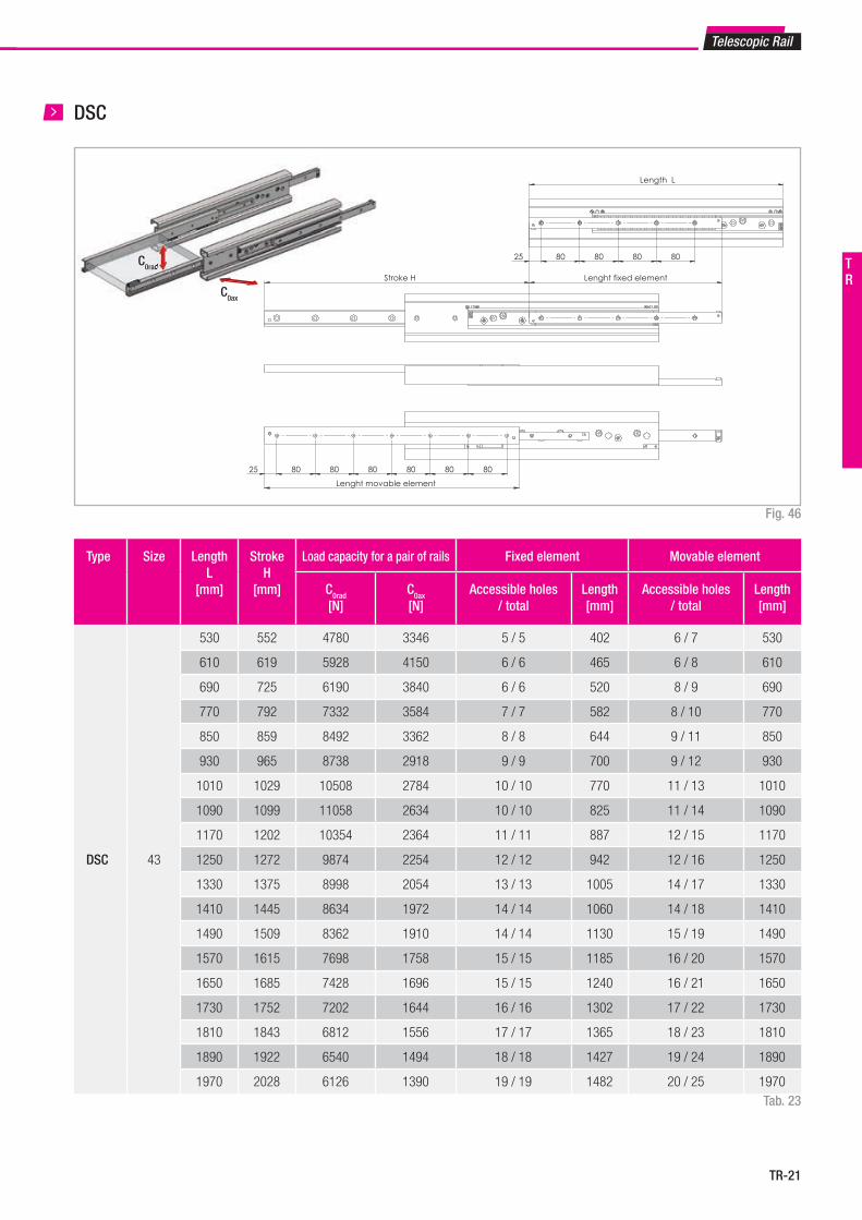
TR-21
Fig. 46
DSC
Tab. 23
Type Size Length L
[mm]
StrokeH
[mm]
Load capacity for a pair of rails Fixed element Movable element
C0rad
[N]C0ax
[N]Accessible holes
/ totalLength [mm]
Accessible holes / total
Length [mm]
DSC 43
530 552 4780 3346 5 / 5 402 6 / 7 530
610 619 5928 4150 6 / 6 465 6 / 8 610
690 725 6190 3840 6 / 6 520 8 / 9 690
770 792 7332 3584 7 / 7 582 8 / 10 770
850 859 8492 3362 8 / 8 644 9 / 11 850
930 965 8738 2918 9 / 9 700 9 / 12 930
1010 1029 10508 2784 10 / 10 770 11 / 13 1010
1090 1099 11058 2634 10 / 10 825 11 / 14 1090
1170 1202 10354 2364 11 / 11 887 12 / 15 1170
1250 1272 9874 2254 12 / 12 942 12 / 16 1250
1330 1375 8998 2054 13 / 13 1005 14 / 17 1330
1410 1445 8634 1972 14 / 14 1060 14 / 18 1410
1490 1509 8362 1910 14 / 14 1130 15 / 19 1490
1570 1615 7698 1758 15 / 15 1185 16 / 20 1570
1650 1685 7428 1696 15 / 15 1240 16 / 21 1650
1730 1752 7202 1644 16 / 16 1302 17 / 22 1730
1810 1843 6812 1556 17 / 17 1365 18 / 23 1810
1890 1922 6540 1494 18 / 18 1427 19 / 24 1890
1970 2028 6126 1390 19 / 19 1482 20 / 25 1970
Telescopic Rail
C0rad0rad
C0ax
TR Lenght fixed element Stroke H
25 80 80 80 80 80 80
Lenght movable element
25 80 80 80 80
Length L
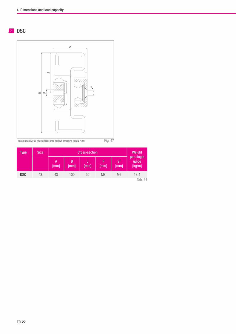
TR-22
4 Dimensions and load capacity
A
B
J
V¹
F
Fig. 47
DSC
Type Size Cross-section Weight per single
guide[kg/m]
A[mm]
B[mm]
J[mm]
F[mm]
V1
[mm]
DSC 43 43 100 50 M8 M6 13.4Tab. 24
1 Fixing holes (V) for countersunk head screws according to DIN 7991
TR-23
C0ax
C0radC
Type Size Length L
[mm]
StrokeH
[mm]
Load capacity for a pair of rails No. ofholes
C0rad
[N]C0ax
[N]
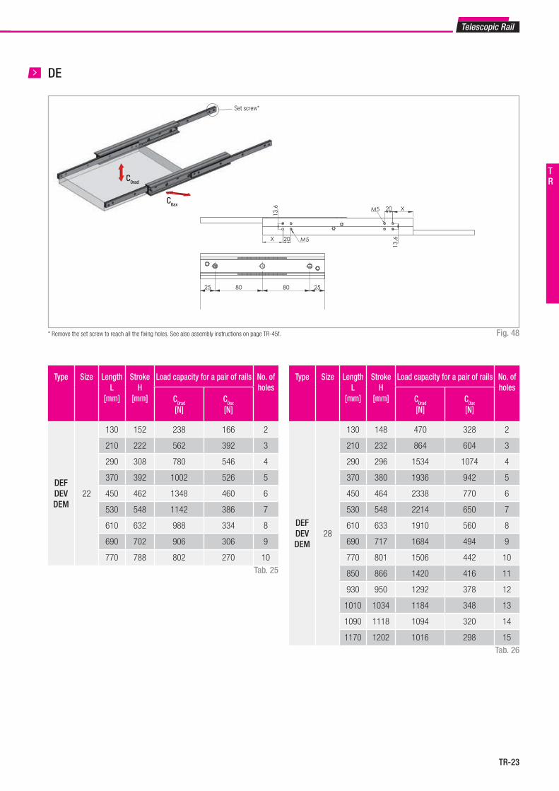
DEFDEVDEM
22
130 152 238 166 2
210 222 562 392 3
290 308 780 546 4
370 392 1002 526 5
450 462 1348 460 6
530 548 1142 386 7
610 632 988 334 8
690 702 906 306 9
770 788 802 270 10
Type Size Length L
[mm]
StrokeH
[mm]
Load capacity for a pair of rails No. ofholes
C0rad
[N]C0ax
[N]
DEFDEVDEM
28
130 148 470 328 2
210 232 864 604 3
290 296 1534 1074 4
370 380 1936 942 5
450 464 2338 770 6
530 548 2214 650 7
610 633 1910 560 8
690 717 1684 494 9
770 801 1506 442 10
850 866 1420 416 11
930 950 1292 378 12
1010 1034 1184 348 13
1090 1118 1094 320 14
1170 1202 1016 298 15
Set screw*
Telescopic Rail
DE
* Remove the set screw to reach all the fi xing holes. See also assembly instructions on page TR-45f. Fig. 48
Tab. 25
Tab. 26
TR
Length L Stroke H
25 80 80 25
X 20 M5
X20M5
13,6
13,6
TR-24
4 Dimensions and load capacity
Type Size Length L
[mm]
StrokeH
[mm]
Load capacity for a pair of rails No. ofholes
C0rad
[N]C0ax
[N]
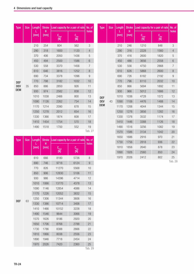
DEFDEVDEM
35
210 254 804 562 3
290 318 1600 1120 4
370 406 2050 1436 5
450 494 2500 1586 6
530 558 3370 1456 7
610 646 3816 1252 8
690 734 3378 1096 9
770 798 3182 1032 10
850 886 2850 926 11
930 974 2582 838 12
1010 1038 2466 800 13
1090 1126 2262 734 14
1170 1214 2090 678 15
1250 1278 2012 654 16
1330 1366 1874 608 17
1410 1454 1754 570 18
1490 1518 1700 552 19
Type Size Length L
[mm]
StrokeH
[mm]
Load capacity for a pair of rails No. ofholes
C0rad
[N]C0ax
[N]
DEFDEVDEM
43
210 246 1210 848 3
290 316 2228 1560 4
370 416 2600 1820 5
450 486 3656 2558 6
530 556 4750 2868 7
610 626 5868 2600 8
690 726 6182 2192 9
770 796 6110 2032 10
850 866 5694 1892 11
930 966 5012 1666 12
1010 1036 4728 1572 13
1090 1106 4476 1488 14
1170 1206 4044 1344 15
1250 1276 3856 1282 16
1330 1376 3532 1174 17
1410 1446 3388 1126 18
1490 1516 3256 1082 19
1570 1586 3134 1042 20
1650 1686 2916 970 21
1730 1756 2818 936 22
1810 1856 2640 878 23
1890 1926 2560 850 24
1970 2026 2412 802 25
Type Size Length L
[mm]
StrokeH
[mm]
Load capacity for a pair of rails No. ofholes
C0rad
[N]C0ax
[N]
DEF 63
610 666 8180 5726 8
690 746 9718 6124 9
770 826 11270 5568 10
850 906 12830 5106 11
930 986 14396 4714 12
1010 1066 13770 4378 13
1090 1146 12854 4086 14
1170 1226 12052 3832 15
1250 1306 11344 3606 16
1330 1386 10714 3406 17
1410 1466 10152 3228 18
1490 1546 9644 3066 19
1570 1626 9186 2920 20
1650 1706 8768 2788 21
1730 1786 8388 2666 22
1810 1866 8038 2556 23
1890 1946 7718 2454 24
1970 2026 7420 2360 25Tab. 29
Tab. 28
Tab. 27
TR-25
Telescopic Rail
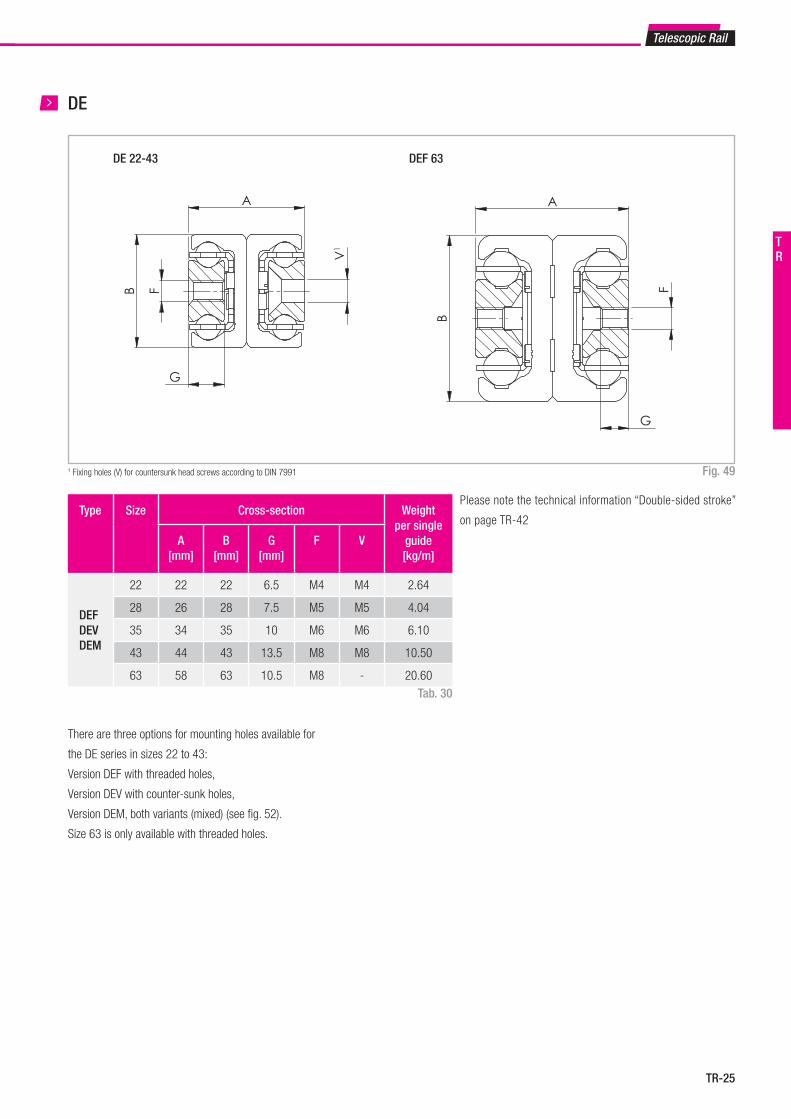
Type Size Cross-section Weight per single
guide[kg/m]
A[mm]
B[mm]
G[mm]
F V
DEFDEVDEM
22 22 22 6.5 M4 M4 2.64
28 26 28 7.5 M5 M5 4.04
35 34 35 10 M6 M6 6.10
43 44 43 13.5 M8 M8 10.50
63 58 63 10.5 M8 - 20.60
DE 22-43 DEF 63
A
B
V1
G
F
A
B
G
F
DE(-F, -V, -M)22-43 DEF63
A
B
V1
G
F
A
B
G
F
DE(-F, -V, -M)22-43 DEF63
DE
1 Fixing holes (V) for countersunk head screws according to DIN 7991 Fig. 49
Tab. 30
There are three options for mounting holes available for
the DE series in sizes 22 to 43:
Version DEF with threaded holes,
Version DEV with counter-sunk holes,
Version DEM, both variants (mixed) (see fig. 52).
Size 63 is only available with threaded holes.
Please note the technical information “Double-sided stroke”
on page TR-42
TR
TR-26
4 Dimensions and load capacity
C0ax
C0radC
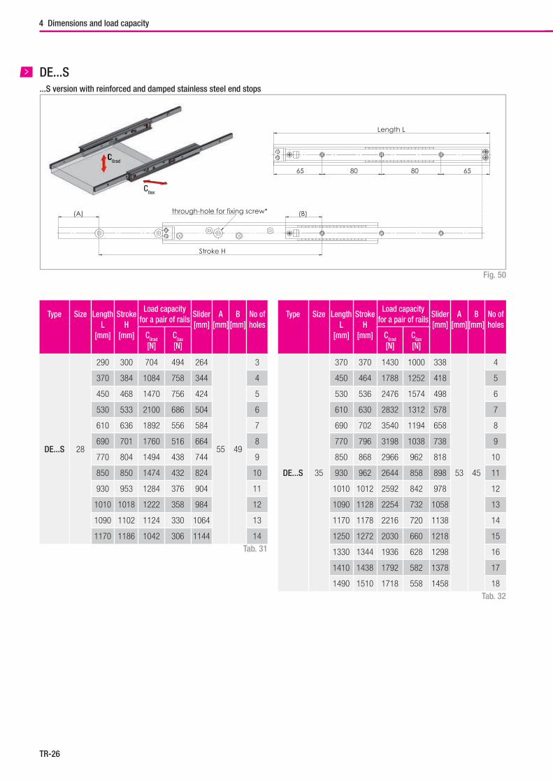
Type Size Length L
[mm]
StrokeH
[mm]
Load capacity for a pair of rails
Slider[mm]
A[mm]
B[mm]
No ofholes
C0rad
[N]C0ax
[N]
DE...S 28
290 300 704 494 264
55 49
3
370 384 1084 758 344 4
450 468 1470 756 424 5
530 533 2100 686 504 6
610 636 1892 556 584 7
690 701 1760 516 664 8
770 804 1494 438 744 9
850 850 1474 432 824 10
930 953 1284 376 904 11
1010 1018 1222 358 984 12
1090 1102 1124 330 1064 13
1170 1186 1042 306 1144 14
Type Size Length L
[mm]
StrokeH
[mm]
Load capacity for a pair of rails
Slider[mm]
A[mm]
B[mm]
No ofholes
C0rad
[N]C0ax
[N]
DE...S 35
370 370 1430 1000 338
53 45
4
450 464 1788 1252 418 5
530 536 2476 1574 498 6
610 630 2832 1312 578 7
690 702 3540 1194 658 8
770 796 3198 1038 738 9
850 868 2966 962 818 10
930 962 2644 858 898 11
1010 1012 2592 842 978 12
1090 1128 2254 732 1058 13
1170 1178 2216 720 1138 14
1250 1272 2030 660 1218 15
1330 1344 1936 628 1298 16
1410 1438 1792 582 1378 17
1490 1510 1718 558 1458 18
Tab. 31
Tab. 32
DE...S
Fig. 50
...S version with reinforced and damped stainless steel end stops
Length L
65 80 65 80
A B
G
F
V¹
(B)
Stroke H
(A) through-hole for fixing screw*
TR-27
Telescopic Rail
Type Size Cross-section Weight per single
guide[kg/m]
A[mm]
B[mm]
G[mm]
F V
DE...S
28 26 28 7.5 M5 M5 4.04
35 34 35 10 M6 M6 6.10
43 44 43 13.5 M8 M8 10.50
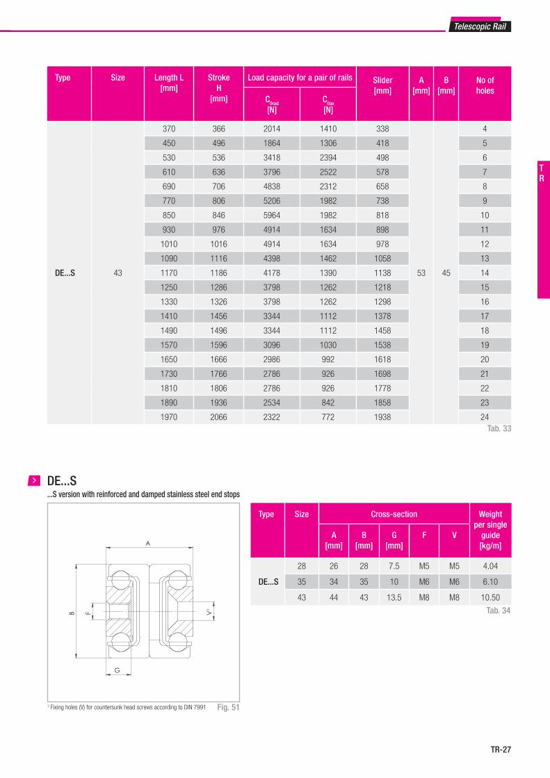
Type Size Length L[mm]
StrokeH
[mm]
Load capacity for a pair of rails Slider[mm]
A[mm]
B[mm]
No ofholes
C0rad
[N]C0ax
[N]
DE...S 43
370 366 2014 1410 338
53 45
4
450 496 1864 1306 418 5
530 536 3418 2394 498 6
610 636 3796 2522 578 7
690 706 4838 2312 658 8
770 806 5206 1982 738 9
850 846 5964 1982 818 10
930 976 4914 1634 898 11
1010 1016 4914 1634 978 12
1090 1116 4398 1462 1058 13
1170 1186 4178 1390 1138 14
1250 1286 3798 1262 1218 15
1330 1326 3798 1262 1298 16
1410 1456 3344 1112 1378 17
1490 1496 3344 1112 1458 18
1570 1596 3096 1030 1538 19
1650 1666 2986 992 1618 20
1730 1766 2786 926 1698 21
1810 1806 2786 926 1778 22
1890 1936 2534 842 1858 23
1970 2066 2322 772 1938 24
Length L
65 80 65 80
A
B
G
F
V¹
(B)
Stroke H
(A) through-hole for fixing screw*
Tab. 33
DE...S
Fig. 51
Tab. 34
1 Fixing holes (V) for countersunk head screws according to DIN 7991
...S version with reinforced and damped stainless steel end stops
TR
TR-28
4 Dimensions and load capacity
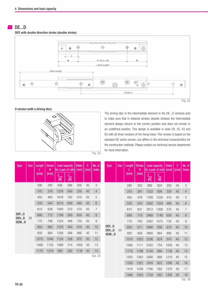
DED with double direction stroke (double stroke)DE...D
Fig. 52
65 65
C
F
V1
A
B
Stroke H
Slider length
L (Rail length)
N° Pitch x 80
Tab. 35
Type Size LengthL
[mm]
StrokeH
[mm]
Load capacity for a pair of rails
Slider[mm]
C[mm]
No. ofholes
C0rad
[N]C0ax
[N]
DEF...D DEV...D DEM...D
35
290 303 890 624 250 45 3
370 391 1322 926 330 45 4
450 479 1760 1232 410 45 5
530 543 2562 1534 490 45 6
610 631 3012 1308 570 45 7
690 719 3460 1140 650 45 8
770 783 3302 1072 730 45 9
850 871 2946 956 810 45 10
930 959 2660 864 890 45 11
1010 1023 2536 824 970 45 12
1090 1111 2322 754 1050 45 13
1170 1199 2140 694 1130 45 14
1250 1263 2060 668 1210 45 15
1330 1351 1916 622 1290 45 16
1410 1439 1790 582 1370 45 17
1490 1503 1734 562 1450 45 18
Type Size LengthL
[mm]
StrokeH
[mm]
Load capacity for a pair of rails
Slider[mm]
C[mm]
No. ofholes
C0rad
[N]C0ax
[N]
DEF...D DEV...D DEM...D
28
290 292 836 586 250 45 3
370 376 1224 856 330 45 4
450 460 1618 782 410 45 5
530 544 2014 658 490 45 6
610 628 1940 570 570 45 7
690 712 1706 500 650 45 8
770 796 1524 448 730 45 9
850 880 1376 404 810 45 10
930 964 1256 368 890 45 11
1010 1048 1154 338 970 45 12
1090 1132 1068 314 1050 45 13
1170 1216 992 292 1130 45 14
Tab. 36
D version (with a driving disc)
Fig. 53
The driving disc in the intermediate element in the DE...D versions acts
to make sure that in bilateral strokes (double strokes) the intermediate
element always returns to the correct position and does not remain in
an undefined position. This design is available in sizes 28, 35, 43 and
63 with all three versions of the fixing holes. This version is based on the
standard DE series version, but differs in the technical characteristics for
the construction methods. Please contact our technical service department
for more information.
TR-29
Fig. 54
DED version D
65 65
A
A
C
C
F
V1
A
B
HubLäuferlänge
L (schienenlänge)
N° Abstände x 80
B
1 Fixing holes (V) for countersunk head screws according to DIN 7991
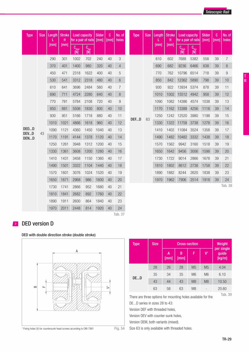
DED with double direction stroke (double stroke)
Type Size LengthL
[mm]
StrokeH
[mm]
Load capacity for a pair of rails
Slider[mm]
C[mm]
No. ofholes
C0rad
[N]C0ax
[N]
DED...DDEV...DDEN...D
43
290 301 1002 702 240 40 3
370 401 1400 980 320 40 4
450 471 2318 1622 400 40 5
530 541 3312 2318 480 40 6
610 641 3696 2484 560 40 7
690 711 4724 2280 640 40 8
770 781 5784 2108 720 40 9
850 881 5506 1830 800 40 10
930 951 5166 1718 880 40 11
1010 1021 4866 1618 960 40 12
1090 1121 4360 1450 1040 40 13
1170 1191 4144 1378 1120 40 14
1250 1261 3948 1312 1200 40 15
1330 1361 3608 1200 1280 40 16
1410 1431 3458 1150 1360 40 17
1490 1501 3322 1104 1440 40 18
1570 1601 3076 1024 1520 40 19
1650 1671 2968 986 1600 40 20
1730 1741 2866 952 1680 40 21
1810 1841 2682 892 1760 40 22
1890 1911 2600 864 1840 40 23
1970 2011 2448 814 1920 40 24
Tab. 37
Type Size LengthL
[mm]
StrokeH
[mm]
Load capacity for a pair of rails
Slider[mm]
C[mm]
No. ofholes
C0rad
[N]C0ax
[N]
DEF...D 63
610 602 7688 5382 558 39 7
690 682 9236 6466 638 39 8
770 762 10796 6514 718 39 9
850 842 12362 5890 798 39 10
930 922 13934 5374 878 39 11
1010 1002 15512 4942 958 39 12
1090 1082 14386 4574 1038 39 13
1170 1162 13388 4256 1118 39 14
1250 1242 12520 3980 1198 39 15
1330 1322 11758 3738 1278 39 16
1410 1402 11084 3524 1358 39 17
1490 1482 10482 3332 1438 39 18
1570 1562 9942 3160 1518 39 19
1650 1642 9456 3006 1598 39 20
1730 1722 9014 2866 1678 39 21
1810 1802 8612 2738 1758 39 22
1890 1882 8244 2620 1838 39 23
1970 1962 7906 2514 1918 39 24
Tab. 38
Type Size Cross-section Weight per single
guide[kg/m]
A[mm]
B[mm]
F V1
DE...D
28 26 28 M5 M5 4.04
35 34 35 M6 M6 6.10
43 44 43 M8 M8 10.50
63 58 63 M8 - 20.60
Tab. 39There are three options for mounting holes available for the
DE...D series in sizes 28 to 43:
Version DEF with threaded holes,
Version DEV with counter-sunk holes,
Version DEM, both variants (mixed).
Size 63 is only available with threaded holes.
Telescopic Rail
TR
TR-30
C0radC0rad
C0ax
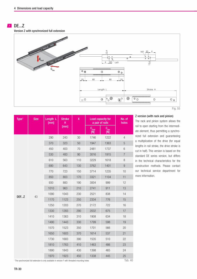
Type1 Size Length L[mm]
StrokeH
[mm]
X Load capacity fora pair of rails
No. ofholes
C0rad
[N]C0ax
[N]
DEF...Z 43
290 243 30 1746 1222 4
370 323 50 1947 1363 5
450 403 70 2481 1737 6
530 483 90 3016 1915 7
610 563 110 3229 1618 8
690 643 130 3762 1401 9
770 723 150 3714 1235 10
850 803 170 3321 1104 11
930 883 190 3004 999 12
1010 963 210 2741 911 13
1090 1043 230 2521 838 14
1170 1123 250 2334 776 15
1250 1203 270 2172 722 16
1330 1283 290 2032 675 17
1410 1363 310 1908 634 18
1490 1443 330 1799 598 19
1570 1523 350 1701 566 20
1650 1603 370 1614 537 21
1730 1683 390 1535 510 22
1810 1763 410 1463 486 23
1890 1843 430 1398 465 24
1970 1923 450 1338 445 25
4 Dimensions and load capacity
Length L Stroke H
25 80 80 25
X 20 M5
X20M5
13,6
13,6
Z version (with rack and pinion)
The rack and pinion system allows the
rail to open starting from the intermedi-
ate element, thus permitting a synchro-
nized full extension and guaranteeing
a multiplication of the drive (for equal
lengths in rail stroke, the drive stroke is
cut in half). This version is based on the
standard DE series version, but differs
in the technical characteristics for the
construction methods. Please contact
our technical service department for
more information.
Tab. 40
Fig. 55
1 The synchronized full extension is only available in version F with threaded mounting holes
DE...ZVersion Z with synchronized full extension
TR-31
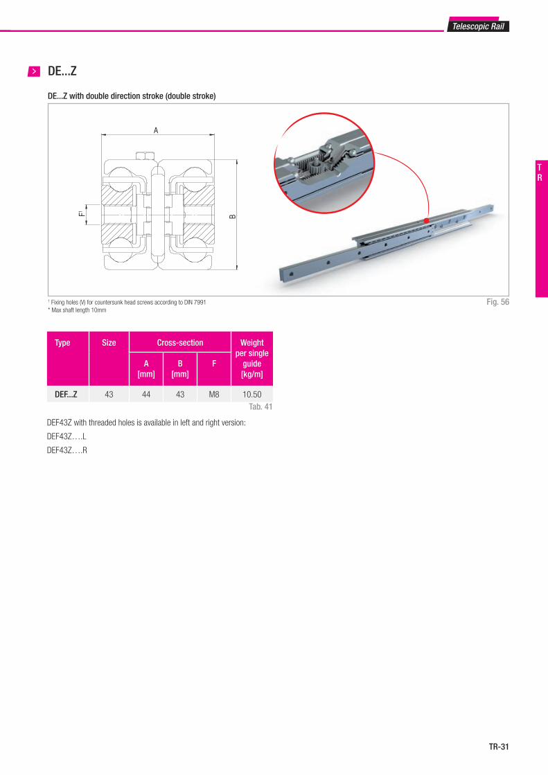
Fig. 56
DE...Z
1 Fixing holes (V) for countersunk head screws according to DIN 7991* Max shaft length 10mm
DE...Z with double direction stroke (double stroke)
Type Size Cross-section Weight per single
guide[kg/m]
A[mm]
B[mm]
F
DEF...Z 43 44 43 M8 10.50Tab. 41
B
A
F1
DEF43Z with threaded holes is available in left and right version:
DEF43Z….L
DEF43Z….R
Telescopic Rail
TR
TR-32
C0ax
Set screw*
C0radC
4 Dimensions and load capacity
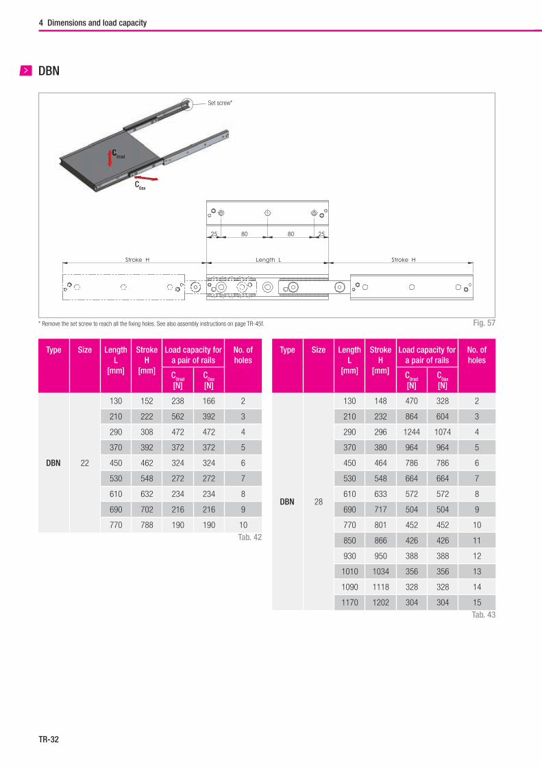
Type Size Length L
[mm]
StrokeH
[mm]
Load capacity for a pair of rails
No. ofholes
C0rad
[N]C0ax
[N]
DBN 22
130 152 238 166 2
210 222 562 392 3
290 308 472 472 4
370 392 372 372 5
450 462 324 324 6
530 548 272 272 7
610 632 234 234 8
690 702 216 216 9
770 788 190 190 10
Type Size Length L
[mm]
StrokeH
[mm]
Load capacity for a pair of rails
No. ofholes
C0rad
[N]C0ax
[N]
DBN 28
130 148 470 328 2
210 232 864 604 3
290 296 1244 1074 4
370 380 964 964 5
450 464 786 786 6
530 548 664 664 7
610 633 572 572 8
690 717 504 504 9
770 801 452 452 10
850 866 426 426 11
930 950 388 388 12
1010 1034 356 356 13
1090 1118 328 328 14
1170 1202 304 304 15Tab. 43
Tab. 42
Fig. 57* Remove the set screw to reach all the fi xing holes. See also assembly instructions on page TR-45f.
DBN
Length LStroke H Stroke H
25 80 80 25
TR-33
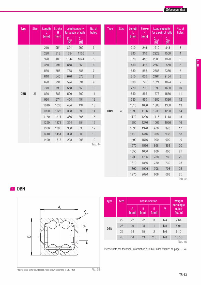
Type Size Length L
[mm]
StrokeH
[mm]
Load capacity for a pair of rails
No. ofholes
C0rad
[N]C0ax
[N]
DBN 35
210 254 804 562 3
290 318 1334 1120 4
370 406 1044 1044 5
450 494 858 858 6
530 558 788 788 7
610 646 676 676 8
690 734 594 594 9
770 798 558 558 10
850 886 500 500 11
930 974 454 454 12
1010 1038 434 434 13
1090 1126 398 398 14
1170 1214 366 366 15
1250 1278 354 354 16
1330 1366 330 330 17
1410 1454 308 308 18
1490 1518 298 298 19
Type Size Length L
[mm]
StrokeH
[mm]
Load capacity for a pair of rails
No. ofholes
C0rad
[N]C0ax
[N]
DBN 43
210 246 1210 848 3
290 316 2228 1560 4
370 416 2600 1820 5
450 486 2662 2558 6
530 556 2386 2386 7
610 626 2164 2164 8
690 726 1824 1824 9
770 796 1690 1690 10
850 866 1576 1576 11
930 966 1386 1386 12
1010 1036 1308 1308 13
1090 1106 1238 1238 14
1170 1206 1118 1118 15
1250 1276 1066 1066 16
1330 1376 976 976 17
1410 1446 938 938 18
1490 1516 900 900 19
1570 1586 868 868 20
1650 1686 806 806 21
1730 1756 780 780 22
1810 1856 730 730 23
1890 1926 708 708 24
1970 2026 668 668 25
Type Size Cross-section Weight per single
guide[kg/m]
A[mm]
B[mm]
E[mm]
V
DBN
22 22 22 3 M4 2.64
28 26 28 1 M5 4.04
35 34 35 2 M6 6.10
43 44 43 2.5 M8 10.50
A
B
V1
E
Please note the technical information “Double-sided stroke” on page TR-42
Telescopic Rail
Tab. 44
Tab. 45
Tab. 46
1 Fixing holes (V) for countersunk head screws according to DIN 7991 Fig. 58
DBN
TR
TR-34
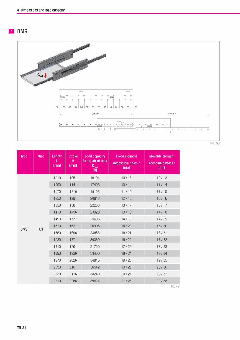
Type Size Length L
[mm]
Stroke H
[mm]
Load capacityfor a pair of rails
C0rad
[N]
Fixed element
Accessible holes / total
Movable element
Accessible holes / total
DMS 63
1010 1051 16104 10 / 13 10 / 13
1090 1141 17496 10 / 14 11 / 14
1170 1216 19168 11 / 15 11 / 15
1250 1291 20848 12 / 16 13 / 16
1330 1381 22238 13 / 17 13 / 17
1410 1456 23920 13 / 18 14 / 18
1490 1531 25608 14 / 19 14 / 19
1570 1621 26996 14 / 20 15 / 20
1650 1696 28686 16 / 21 16 / 21
1730 1771 30380 16 / 22 17 / 22
1810 1861 31766 17 / 23 17 / 23
1890 1936 33460 18 / 24 19 / 24
1970 2026 34846 19 / 25 19 / 25
2050 2101 36542 19 / 26 20 / 26
2130 2176 38240 20 / 27 20 / 27
2210 2266 39624 21 / 28 22 / 28
4 Dimensions and load capacity
C0radC0rad
DMS
Fig. 59
Tab. 47
Length L Stroke H
25 80 80 80 80 80 80 80 80 80 80 80 80 25
TR-35
Type Size Cross-section Weight per single
guide[kg/m]
A[mm]
B[mm]
I[mm]
K[mm]
D[mm]
J[mm]
C V
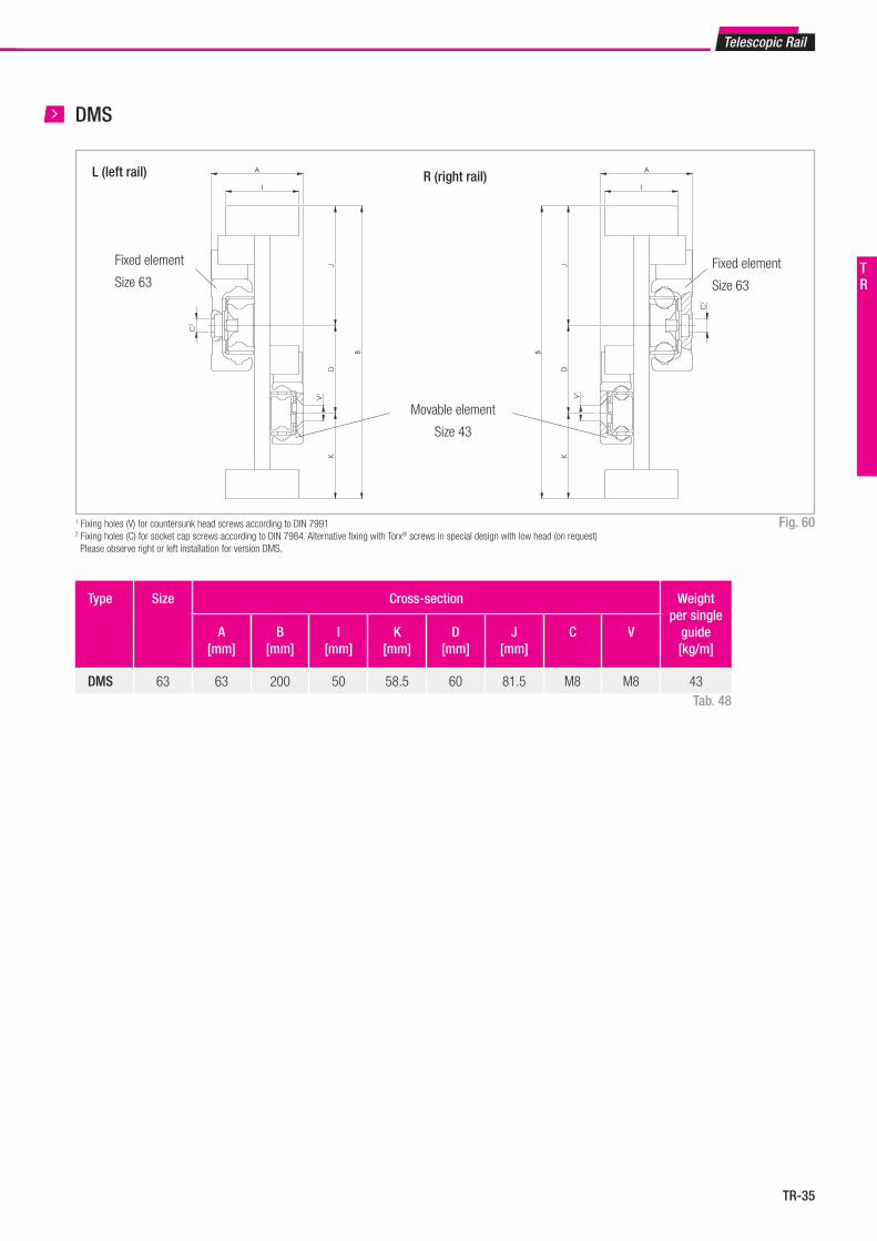
DMS 63 63 200 50 58.5 60 81.5 M8 M8 43
I
A
B
JD
K
V1
C2
I
B
A
JD
K
C2
V1
I
A
B
JD
K
V1
C2
I
B
A
JD
K
C2
V1
Telescopic Rail
Tab. 48
1 Fixing holes (V) for countersunk head screws according to DIN 79912 Fixing holes (C) for socket cap screws according to DIN 7984. Alternative fixing with Torx® screws in special design with low head (on request) Please observe right or left installation for version DMS.
Fig. 60
DMS
Fixed element
Size 63
L (left rail) R (right rail)
Fixed element
Size 63
Movable element
Size 43
TR
TR-36
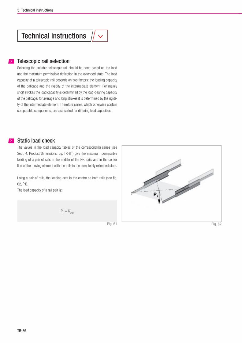
P1 = C
0rad
Static load check
5 Technical instructions
Technical instructions
Telescopic rail selectionSelecting the suitable telescopic rail should be done based on the load
and the maximum permissible deflection in the extended state. The load
capacity of a telescopic rail depends on two factors: the loading capacity
of the ballcage and the rigidity of the intermediate element. For mainly
short strokes the load capacity is determined by the load-bearing capacity
of the ballcage; for average and long strokes it is determined by the rigidi-
ty of the intermediate element. Therefore series, which otherwise contain
comparable components, are also suited for differing load capacities.
The values in the load capacity tables of the corresponding series (see
Sect. 4, Product Dimensions, pg. TR-8ff) give the maximum permissible
loading of a pair of rails in the middle of the two rails and in the center
line of the moving element with the rails in the completely extended state.
Using a pair of rails, the loading acts in the centre on both rails (see fig.
62, P1).
The load capacity of a rail pair is:
Fig. 62Fig. 61
TR-37
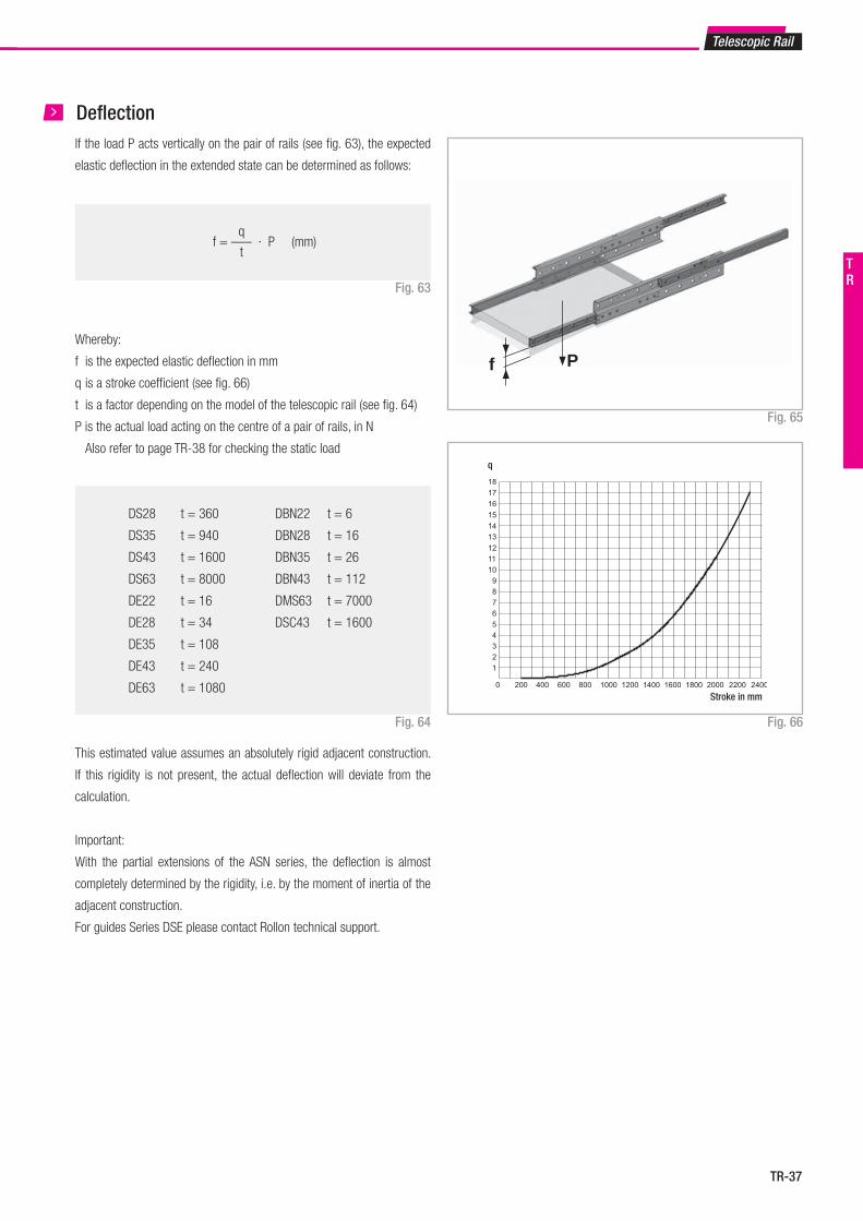
f = ––– · P (mm)q
t
q
f P
Telescopic Rail
DeflectionIf the load P acts vertically on the pair of rails (see fig. 63), the expected
elastic deflection in the extended state can be determined as follows:
Fig. 63
Fig. 65
Whereby:
f is the expected elastic deflection in mm
q is a stroke coefficient (see fig. 66)
t is a factor depending on the model of the telescopic rail (see fig. 64)
P is the actual load acting on the centre of a pair of rails, in N
Also refer to page TR-38 for checking the static load
Fig. 66
Stroke in mm
DS28 t = 360
DS35 t = 940
DS43 t = 1600
DS63 t = 8000
DE22 t = 16
DE28 t = 34
DE35 t = 108
DE43 t = 240
DE63 t = 1080
DBN22 t = 6
DBN28 t = 16
DBN35 t = 26
DBN43 t = 112
DMS63 t = 7000
DSC43 t = 1600
Fig. 64
This estimated value assumes an absolutely rigid adjacent construction.
If this rigidity is not present, the actual deflection will deviate from the
calculation.
Important:
With the partial extensions of the ASN series, the deflection is almost
completely determined by the rigidity, i.e. by the moment of inertia of the
adjacent construction.
For guides Series DSE please contact Rollon technical support.
TR
TR-38
P0rad
1
C0rad
S0
≤P
0ax 1
C0ax
S0
≤M
1 1
Mx S
0
≤M
2 1
My S
0
≤M
3 1
Mz S
0
≤
5 Technical instructions
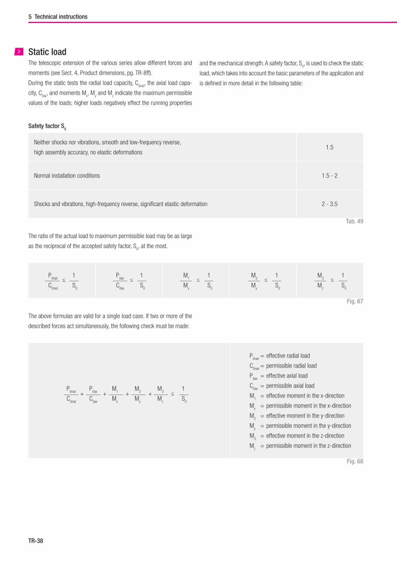
Fig. 68
The above formulas are valid for a single load case. If two or more of the
described forces act simultaneously, the following check must be made:
Fig. 67
The ratio of the actual load to maximum permissible load may be as large
as the reciprocal of the accepted safety factor, S0, at the most.
Neither shocks nor vibrations, smooth and low-frequency reverse,
high assembly accuracy, no elastic deformations1.5
Normal installation conditions 1.5 - 2
Shocks and vibrations, high-frequency reverse, significant elastic deformation 2 - 3.5
Tab. 49
Safety factor S0
and the mechanical strength. A safety factor, S0, is used to check the static
load, which takes into account the basic parameters of the application and
is defined in more detail in the following table:
Static loadThe telescopic extension of the various series allow different forces and
moments (see Sect. 4, Product dimensions, pg. TR-8ff).
During the static tests the radial load capacity, C0rad
, the axial load capa-
city, C0ax
, and moments Mx, M
y and M
z indicate the maximum permissible
values of the loads; higher loads negatively effect the running properties
P0rad
P0ax
M1 M
2 M
3
C0rad
C0ax
Mx M
y M
z
+ + + + ≤1
S0
P0rad
= effective radial load
C0rad
= permissible radial load
P0ax
= effective axial load
C0ax
= permissible axial load
M1 = effective moment in the x-direction
Mx = permissible moment in the x-direction
M2 = effective moment in the y-direction
My = permissible moment in the y-direction
M3 = effective moment in the z-direction
Mz = permissible moment in the z-direction
TR-39
ASN, DS, DE, DBN, DSC
Neither shocks nor vibrations, smooth and low-frequency direction change,
clean environment1.3 - 1.8
Light vibrations and average direction change 1.8 - 2.3
Shocks and vibrations, high-frequency direction change, very dirty environment 2.3 - 3.5
Telescopic Rail
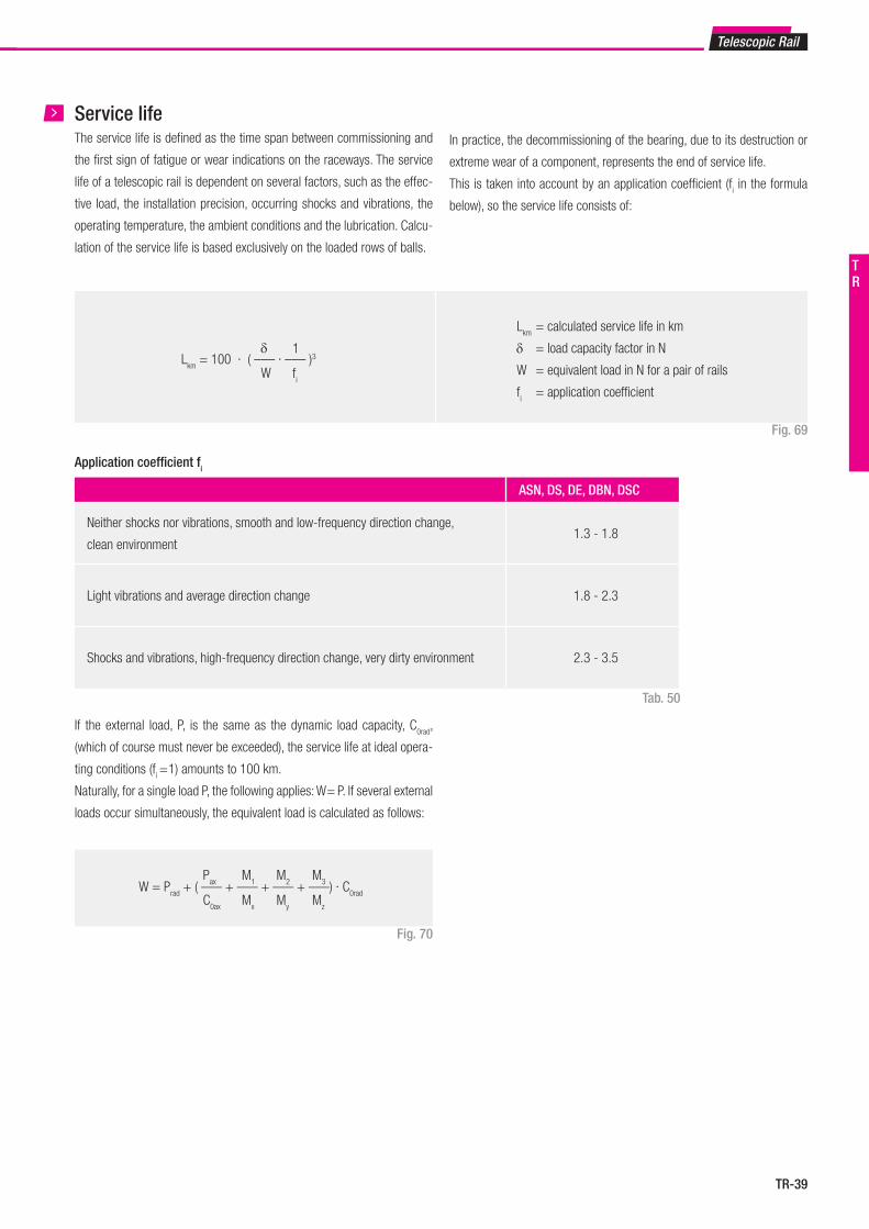
Lkm
= 100 · ( ––– · ––– )3δ
W
1
fi
Lkm
= calculated service life in km
δ = load capacity factor in N
W = equivalent load in N for a pair of rails
fi = application coefficient
Fig. 70
If the external load, P, is the same as the dynamic load capacity, C0rad
,
(which of course must never be exceeded), the service life at ideal opera-
ting conditions (fi = 1) amounts to 100 km.
Naturally, for a single load P, the following applies: W = P. If several external
loads occur simultaneously, the equivalent load is calculated as follows:
Tab. 50
Application coefficient fi
Fig. 69
The service life is defined as the time span between commissioning and
the first sign of fatigue or wear indications on the raceways. The service
life of a telescopic rail is dependent on several factors, such as the effec-
tive load, the installation precision, occurring shocks and vibrations, the
operating temperature, the ambient conditions and the lubrication. Calcu-
lation of the service life is based exclusively on the loaded rows of balls.
In practice, the decommissioning of the bearing, due to its destruction or
extreme wear of a component, represents the end of service life.
This is taken into account by an application coefficient (fi in the formula
below), so the service life consists of:
Service life
W = Prad
+ ( ––– + ––– + ––– + –––) · C0rad
Pax
C0ax
M1
Mx
M2
My
M3
Mz
TR
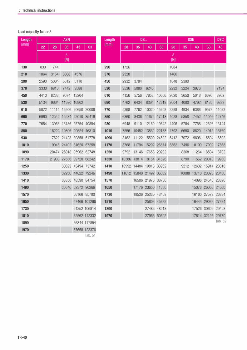
TR-40
5 Technical instructions
Load capacity factor δ
Length[mm]
ASN
22 28 35 43 63
δ[N]
130 830 1744
210 1864 3154 3066 4576
290 2590 5384 5812 8110
370 3330 6810 7442 9588
450 4410 8238 9074 13204
530 5134 9664 11980 16902
610 5872 11114 13606 20650 30006
690 6960 12542 15234 22010 35416
770 7684 13968 18186 25754 40854
850 16222 19806 29524 46310
930 17622 21428 30858 51778
1010 19048 24402 34620 57258
1090 20474 26018 35962 62748
1170 21900 27636 39720 68242
1250 30622 43494 73742
1330 32236 44822 79246
1410 33850 48590 84754
1490 36846 52372 90266
1570 56166 95780
1650 57466 101296
1730 61252 106814
1810 62562 112332
1890 66344 117854
1970 67658 123376
Length[mm]
DS... DSE DSC
28 35 43 63 28 35 43 63 43
δ[N]
290 1726 1084
370 2328 1466
450 2932 3784 1848 2390
530 3536 5080 6240 2232 3224 3976 7194
610 4156 5756 7858 10656 2620 3650 5018 6690 8902
690 4762 6434 8394 12918 3004 4080 4792 8126 9322
770 5368 7762 10020 15208 3388 4934 6388 9578 11022
850 6360 8436 11672 17518 4028 5358 7452 11046 12746
930 6948 9110 12180 19842 4406 5784 7758 12526 13144
1010 7556 10452 13832 22178 4792 6650 8820 14012 15760
1090 8162 11122 15500 24522 5412 7072 9896 15504 16592
1170 8768 11794 15292 26874 5562 7496 10190 17002 17868
1250 9792 13146 17658 29232 8368 11264 18504 18702
1330 10386 13814 18154 31596 8790 11562 20010 19980
1410 10992 14484 19818 33962 9212 12632 15914 20818
1490 11612 15840 21492 36332 10088 13710 23028 23456
1570 16506 21976 38706 14096 24540 23826
1650 17176 23650 41080 15078 26056 24660
1730 18536 25330 43458 16160 27572 26394
1810 25808 45838 16444 29088 27824
1890 27486 48218 17526 30606 29408
1970 27966 50602 17814 32126 29770
Tab. 51
Tab. 52
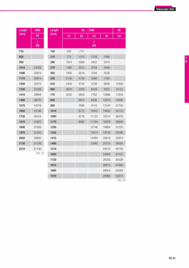
TR-41
Telescopic Rail
Length[mm]
DE... / DBN DE
22 28 35 43 63
δ[N]
130 330 714
210 772 1310 1228 1846
290 1074 2306 2422 3374
370 1380 2912 3104 3948
450 1850 3518 3784 5528
530 2150 4126 5080 7160
610 2458 4744 5756 8828 12406
690 2934 5350 6434 9322 14722
770 3232 5958 7762 10986 17054
850 6974 8436 12670 19398
930 7566 9110 13144 21750
1010 8172 10452 14822 24110
1090 8776 11122 16514 26476
1170 9382 11794 16978 28846
1250 13146 18664 31220
1330 13814 19136 33596
1410 14484 20818 35974
1490 15840 22510 38356
1570 24210 40738
1650 24660 43122
1730 26356 45508
1810 26812 47896
1890 28504 50284
1970 28966 52672
Tab. 54
Length[mm]
DMS
63
δ[N]
770
850
930
1010 24308
1090 29974
1170 28914
1250 32972
1330 33526
1410 39684
1490 38570
1570 44316
1650 43196
1730 49414
1810 47822
1890 51926
1970 52450
2050 58682
2130 57526
2210 61190Tab. 53
TR
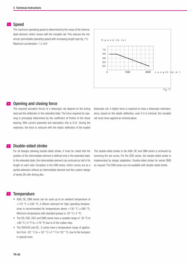
TR-42
0 1000 2000 Länge (mm)
0.20.4
0.6
0.8
1.0
Geschwindigkeit (m/s)
5 Technical instructions
SpeedThe maximum operating speed is determined by the mass of the interme-
diate element, which moves with the movable rail. This reduces the ma-
ximum permissible operating speed with increasing length (see fig. 71).
Maximum acceleration: 1.2 m/s2
Fig. 71
Opening and closing forceThe required actuation forces of a telescopic rail depend on the acting
load and the deflection in the extended state. The force required for ope-
ning is principally determined by the coefficient of friction of the linear
bearing. With correct assembly and lubrication, this is 0.01. During the
extension, the force is reduced with the elastic deflection of the loaded
telescopic rail. A higher force is required to close a telescopic extension,
since, based on the elastic deflection, even if it is minimal, the movable
rail must move against an inclined plane.
Double-sided strokeFor all designs allowing double-sided stroke, it must be noted that the
position of the intermediate element is defined only in the extended state.
In the extended state, the intermediate element can protrude by half of its
length on each side. Exception is the ASN series, which comes out as a
partial extension without an intermediate element and the custom design
of series DE with driving disc.
The double-sided stroke in the ASN, DE and DBN series is achieved by
removing the set screw. For the DSD series, the double-sided stroke is
implemented by design adaptation. Double-sided stroke for series DMS
on request. The DSB series are not available with double-sided stroke.
Temperature■ ASN, DE, DBN series can be used up to an ambient temperature of
+170 °C (+338 °F). A lithium lubricant for high operating tempera-
tures is recommended for temperatures above +130 °C (+266 °F).
Minimum temperature with standard grease is -20 °C (-4 °F).
■ The DS, DSE, DSC and DMS series have a useable range of -20 °C to
+80 °C (-4 °F to +176 °F) due to of the rubber stop.
■ The DSS43S and DE...S series have a temperature range of applica-
tion from -20 ° C to + 50 ° C (-4 ° F to 122 ° F), due to the bumpers
in special resin.
S p e e d ( m / s )
L e n g t h ( m m )
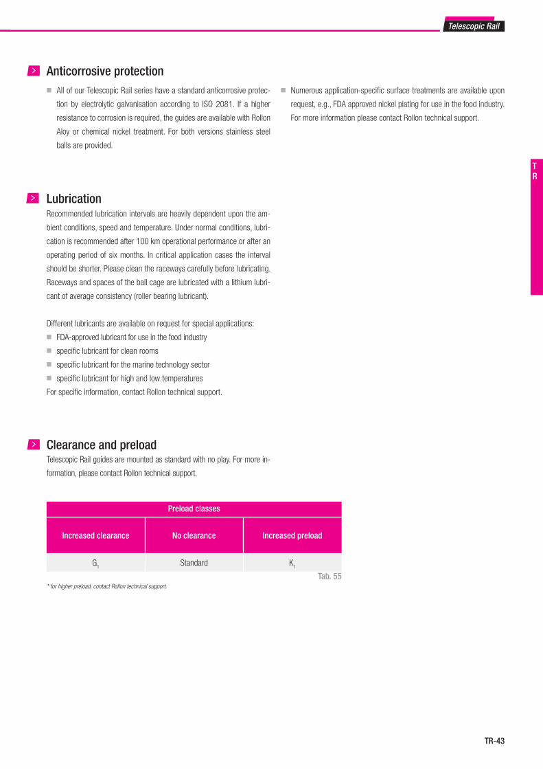
TR-43
Telescopic Rail
Anticorrosive protection■ All of our Telescopic Rail series have a standard anticorrosive protec-
tion by electrolytic galvanisation according to ISO 2081. If a higher
resistance to corrosion is required, the guides are available with Rollon
Aloy or chemical nickel treatment. For both versions stainless steel
balls are provided.
■ Numerous application-specific surface treatments are available upon
request, e.g., FDA approved nickel plating for use in the food industry.
For more information please contact Rollon technical support.
LubricationRecommended lubrication intervals are heavily dependent upon the am-
bient conditions, speed and temperature. Under normal conditions, lubri-
cation is recommended after 100 km operational performance or after an
operating period of six months. In critical application cases the interval
should be shorter. Please clean the raceways carefully before lubricating.
Raceways and spaces of the ball cage are lubricated with a lithium lubri-
cant of average consistency (roller bearing lubricant).
Different lubricants are available on request for special applications:
■ FDA-approved lubricant for use in the food industry
■ specific lubricant for clean rooms
■ specific lubricant for the marine technology sector
■ specific lubricant for high and low temperatures
For specific information, contact Rollon technical support.
Clearance and preloadTelescopic Rail guides are mounted as standard with no play. For more in-
formation, please contact Rollon technical support.
* for higher preload, contact Rollon technical support.
Preload classes
Increased clearance No clearance Increased preload
G1
Standard K1
Tab. 55
TR
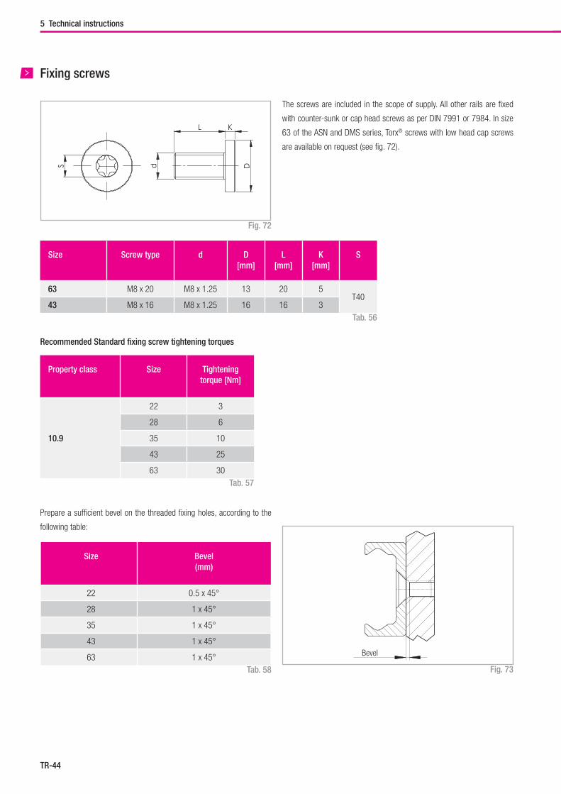
TR-44
Property class Size Tightening torque [Nm]
10.9
22 3
28 6
35 10
43 25
63 30
S d
L K
DSize Screw type d D
[mm]L
[mm]K
[mm]S
63 M8 x 20 M8 x 1.25 13 20 5T40
43 M8 x 16 M8 x 1.25 16 16 3
5 Technical instructions
Tab. 58
Prepare a sufficient bevel on the threaded fixing holes, according to the
following table:
Bevel
Size Bevel(mm)
22 0.5 x 45°
28 1 x 45°
35 1 x 45°
43 1 x 45°
63 1 x 45°Fig. 73
Fixing screws
The screws are included in the scope of supply. All other rails are fixed
with counter-sunk or cap head screws as per DIN 7991 or 7984. In size
63 of the ASN and DMS series, Torx® screws with low head cap screws
are available on request (see fig. 72).
Fig. 72
Tab. 56
Recommended Standard fixing screw tightening torques
Tab. 57
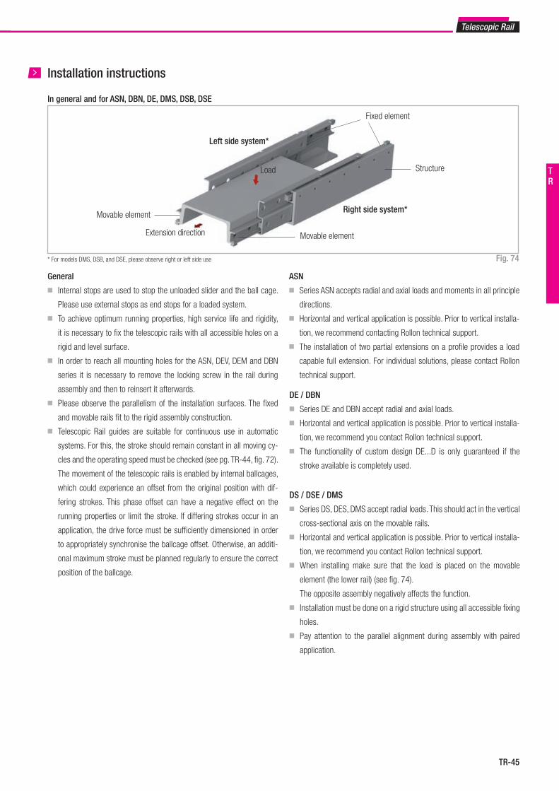
TR-45
Movable element
Load
Fixed element
Movable element
Structure
Right side system*
Left side system*
Extension direction
* For models DMS, DSB, and DSE, please observe right or left side use
Telescopic Rail
Installation instructions
Fig. 74
General
■ Internal stops are used to stop the unloaded slider and the ball cage.
Please use external stops as end stops for a loaded system.
■ To achieve optimum running properties, high service life and rigidity,
it is necessary to fix the telescopic rails with all accessible holes on a
rigid and level surface.
■ In order to reach all mounting holes for the ASN, DEV, DEM and DBN
series it is necessary to remove the locking screw in the rail during
assembly and then to reinsert it afterwards.
■ Please observe the parallelism of the installation surfaces. The fixed
and movable rails fit to the rigid assembly construction.
■ Telescopic Rail guides are suitable for continuous use in automatic
systems. For this, the stroke should remain constant in all moving cy-
cles and the operating speed must be checked (see pg. TR-44, fig. 72).
The movement of the telescopic rails is enabled by internal ballcages,
which could experience an offset from the original position with dif-
fering strokes. This phase offset can have a negative effect on the
running properties or limit the stroke. If differing strokes occur in an
application, the drive force must be sufficiently dimensioned in order
to appropriately synchronise the ballcage offset. Otherwise, an additi-
onal maximum stroke must be planned regularly to ensure the correct
position of the ballcage.
ASN
■ Series ASN accepts radial and axial loads and moments in all principle
directions.
■ Horizontal and vertical application is possible. Prior to vertical installa-
tion, we recommend contacting Rollon technical support.
■ The installation of two partial extensions on a profile provides a load
capable full extension. For individual solutions, please contact Rollon
technical support.
DE / DBN
■ Series DE and DBN accept radial and axial loads.
■ Horizontal and vertical application is possible. Prior to vertical installa-
tion, we recommend you contact Rollon technical support.
■ The functionality of custom design DE...D is only guaranteed if the
stroke available is completely used.
DS / DSE / DMS
■ Series DS, DES, DMS accept radial loads. This should act in the vertical
cross-sectional axis on the movable rails.
■ Horizontal and vertical application is possible. Prior to vertical installa-
tion, we recommend you contact Rollon technical support.
■ When installing make sure that the load is placed on the movable
element (the lower rail) (see fig. 74).
The opposite assembly negatively affects the function.
■ Installation must be done on a rigid structure using all accessible fixing
holes.
■ Pay attention to the parallel alignment during assembly with paired
application.
In general and for ASN, DBN, DE, DMS, DSB, DSE
TR
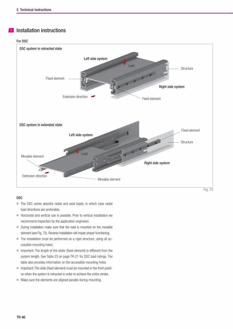
TR-46
Installation instructions
Load
Fixed element
Structure
Right side system
Left side system
Extension direction
For DSC
Fixed element
DSC system in retracted state
Load
Structure
Right side system
Left side system
Extension direction
Fixed element
DSC system in extended state
Movable element
Movable element
DSC
■ The DSC series absorbs radial and axial loads, in which case radial
load directions are preferable.
■ Horizontal and vertical use is possible. Prior to vertical installation we
recommend inspection by the application engineers.
■ During installation make sure that the load is mounted on the movable
element (see Fig. 75). Reverse installation will impair proper functioning.
■ The installation must be performed on a rigid structure, using all ac-
cessible mounting holes.
■ Important: The length of the slider (fixed element) is different from the
system length. See Table 23 on page TR-21 for DSC load ratings. The
table also provides information on the accessible mounting holes.
■ Important: The slide (fixed element) must be mounted in the front positi-
on when the system is retracted in order to achieve the entire stroke.
■ Make sure the elements are aligned parallel during mounting.
Fig. 75
5 Technical instructions
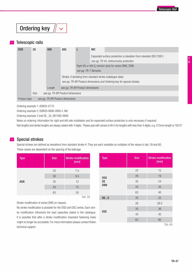
TR-47
Type Size Stroke modification [mm]
ASN
22 7.5
28 9.5
35 12
43 15
63 20
DSB 28 690 885 L NIC
Expanded surface protection is deviation from standard (ISO 2081)
see pg. TR-45, Anticorrosive protection
Right (R) or left (L) version (only for series DMS, DSB)
see pg. TR-7 Remarks
Stroke, if deviating from standard stroke (catalogue data)
see pg. TR-8ff Product dimensions and Ordering key for special strokes
Length see pg. TR-8ff Product dimensions
Size see pg. TR-8ff Product dimensions
Product type see pg. TR-8ff Product dimensions
Ordering key
Telescopic Rail
Telescopic rails
Ordering example 1: ASN35-0770
Ordering example 2: DSB28-0690-0885-L-NIC
Ordering example 3 (rail DE...D): DEF28D-0690
Notes on ordering: Information for right and left side installation and for expanded surface protection is only necessary if required.
Rail lengths and stroke lengths are always stated with 4 digits. Please pad with zeroes to fill in for lengths with less than 4 digits, e.g. 515mm length is “0515”
Special strokesSpecial strokes are defined as deviations from standard stroke H. They are each available as multiples of the values in tab. 59 and 60.
These values are dependent on the spacing of the ballcage.
Tab. 59
Tab. 60
Stroke modification of series DMS on request.
No stroke modification is possible for the DSD and DSC series. Each stro-
ke modification influences the load capacities stated in the catalogue.
It is possible that after a stroke modification important fastening holes
might no longer be accessible. For more information please contact Rollon
technical support.
Type Size Stroke modification [mm]
DSSDEDBN
22 15
28 19
35 24
43 30
63 40
DE...S 35 22
DSE
28 28.5
35 36
43 45
63 60
TR

Hegra Rail
FrontespizioHegra.indd 1 28/09/2018 13:17:25
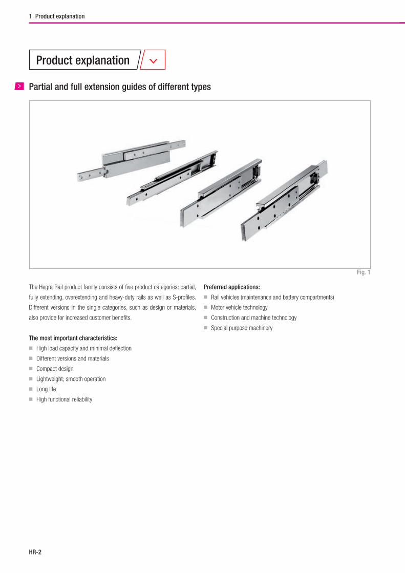
Hegra Rail
HR-2
Fig. 1
1 Product explanation
Partial and full extension guides of different types
Product explanation
The Hegra Rail product family consists of five product categories: partial,
fully extending, overextending and heavy-duty rails as well as S-profiles.
Different versions in the single categories, such as design or materials,
also provide for increased customer benefits.
The most important characteristics:
■ High load capacity and minimal deflection
■ Different versions and materials
■ Compact design
■ Lightweight; smooth operation
■ Long life
■ High functional reliability
Preferred applications:
■ Rail vehicles (maintenance and battery compartments)
■ Motor vehicle technology
■ Construction and machine technology
■ Special purpose machinery
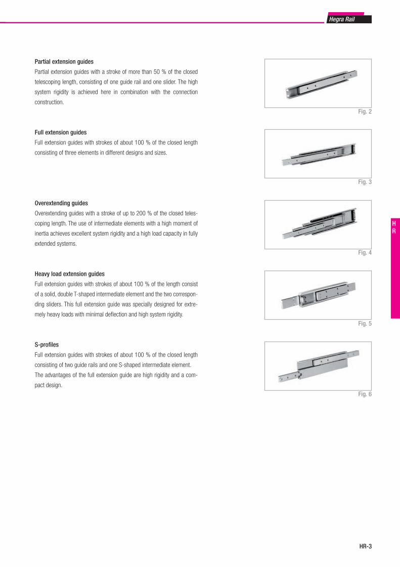
HR-3
Hegra Rail
HR
Fig. 2
Fig. 3
Fig. 4
Fig. 5
Fig. 6
Partial extension guides
Partial extension guides with a stroke of more than 50 % of the closed
telescoping length, consisting of one guide rail and one slider. The high
system rigidity is achieved here in combination with the connection
construction.
Full extension guides
Full extension guides with strokes of about 100 % of the closed length
consisting of three elements in different designs and sizes.
Overextending guides
Overextending guides with a stroke of up to 200 % of the closed teles-
coping length. The use of intermediate elements with a high moment of
inertia achieves excellent system rigidity and a high load capacity in fully
extended systems.
Heavy load extension guides
Full extension guides with strokes of about 100 % of the length consist
of a solid, double T-shaped intermediate element and the two correspon-
ding sliders. This full extension guide was specially designed for extre-
mely heavy loads with minimal defl ection and high system rigidity.
S-profi les
Full extension guides with strokes of about 100 % of the closed length
consisting of two guide rails and one S-shaped intermediate element.
The advantages of the full extension guide are high rigidity and a com-
pact design.
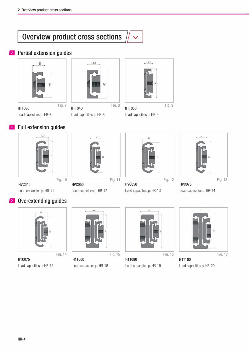
Hegra Rail
HR-4
Overview product cross sections
2 Overview product cross sections
HTT030
Load capacities p. HR-7
Fig. 7
Partial extension guides
Fig. 9HTT040
Load capacities p. HR-8
HTT050
Load capacities p. HR-9
Full extension guides
Fig. 10 Fig. 11HVC058
Load capacities p. HR-13
HVC075
Load capacities p. HR-14
Fig. 12 Fig. 13
X
P
Länge L
Y m n E n m YX
C
Hub H
12
2
1
J B
A
V
K
G
F
15
30
1
HTT030-0550
Y m n E n m YX
CLänge L
Hub H
1 22
XP
1
J B
K
V
A
G
F
1
18,5
40HTT040-0550
19,5
50
HVC045
Load capacities p. HR-11
20,5
45
HVC050
Load capacities p. HR-12
22,1
50
24
58
XX
Länge L
Y m n E n m Y
C
Hub H
11 2
2
P
D B
A
VK
J
G
F
1
26
75
HVC045-0550HVC050-0550HVC058-0550HVC075-0550
Fig. 8
Overextending guides
H1T060
Load capacities p. HR-18
Fig. 14 Fig. 15 Fig. 16H1T080
Load capacities p. HR-19
Fig. 17H1T100
Load capacities p. HR-20
H1C075
Load capacities p. HR-16
P
YX
m n E n m YX
CLänge L
Hub H
1 2
J B
G
A
V
DK
F
1
30,1
75
J = 20G = 10
H1C075-0550
m n
Y m n E n m Y
Länge LC
Hub H
1 2
J B
A
KDJ
GG
FF
1
1
1
2
2
2
40,5
60
H1T060-0550H1T080-1100
m n
Y m n E n m Y
Länge LC
Hub H
1 2
J B
A
KDJ
GG
FF
1
1
1
2
2
2
44
80
H1T060-0550H1T080-1100
m n
Y m n E n m YC
Länge L
Hub H
1 2
D J B
A
GG
J D
F
F
1
1
1
2
2
2
1 2
51
100
H1T100-1100H1T150-1100
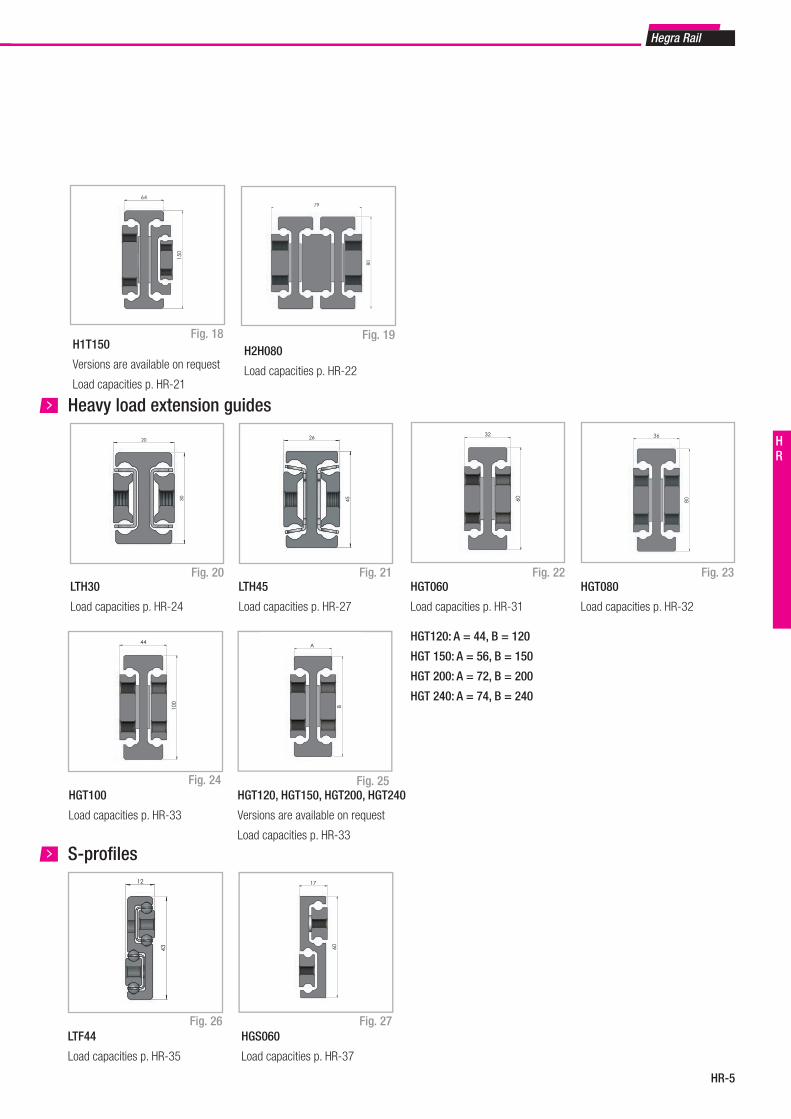
HR-5
Hegra Rail
HR
Fig. 19H2H080
Load capacities p. HR-22
Fig. 18
Fig. 20
Heavy load extension guides
Fig. 21LTH30
Load capacities p. HR-24
LTH45
Load capacities p. HR-27
Fig. 22 Fig. 23
Fig. 24 Fig. 25
HGT060
Load capacities p. HR-31
HGT100
Load capacities p. HR-33
HGT080
Load capacities p. HR-32
m n
Y m n E n m Y
C
Länge L
Hub H
D J B
G
A
DJ
G
K
FF
79
80
H2D080-0800
60
32
m n
Y m n E n m YC
Länge L
Hub H
D J BDJ
GG
A
K
FF
80
36
HGT060-0550HGT070-0550HGT080-1100HGT100-1100HGT120-1100HGT150-1100HGT200-1100HGT240-1100
100
44
20
30
26
45
H1T150
Versions are available on request
Load capacities p. HR-21
150
64
HGT120, HGT150, HGT200, HGT240
Versions are available on request
Load capacities p. HR-33
HGT120: A = 44, B = 120
HGT 150: A = 56, B = 150
HGT 200: A = 72, B = 200
HGT 240: A = 74, B = 240
A
B
HGS060
Load capacities p. HR-37
Fig. 26
S-profi les
Fig. 27LTF44
Load capacities p. HR-35
17
60
12
43
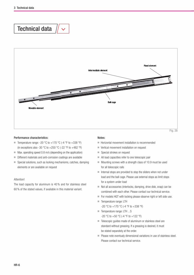
Hegra Rail
HR-6
3 Technical data
Fig. 28
Notes:
■ Horizontal movement installation is recommended
■ Vertical movement installation on request
■ Special strokes on request
■ All load capacities refer to one telescopic pair
■ Mounting screws with a strength class of 10.9 must be used
for all telescopic rails
■ Internal stops are provided to stop the sliders when not under
load and the ball cage. Please use external stops as limit stops
for a system under load
■ Not all accessories (interlocks, damping, drive disk, snap) can be
combined with each other. Please contact our technical service.
■ For models HGT with locking please observe right or left side use.
■ Temperature range: LTH
-20 °C to +170 °C (-4 °F to +338 °F)
■ Temperature range: LTH ...S
-20 °C to +50 °C (-4 °F to +122 °F)
■ Telescopic guides made of aluminum or stainless steel are
standard without greasing. If a greasing is desired, it must
be stated separately at the order.
■ Please note eventualy dimensional variations in use of stainless steel.
Please contact our technical service.
Performance characteristics:
■ Temperature range: -20 °C to +170 °C (-4 °F to +338 °F)
(in exceptions also -30 °C to +250 °C ( -22 °F to +482 °F)
■ Max. operating speed 0.8 m/s (depending on the application)
■ Different materials and anti-corrosion coatings are available
■ Special solutions, such as locking mechanisms, catches, damping
elements or are available on request
Attention!
The load capacity for aluminum is 40 % and for stainless steel
60 % of the stated values, if available in this material variant.
Technical data
Movable element
Intermediate element
Ball cage
Fixed element
Movable element
Intermediate element
Ball cage
Fixed element
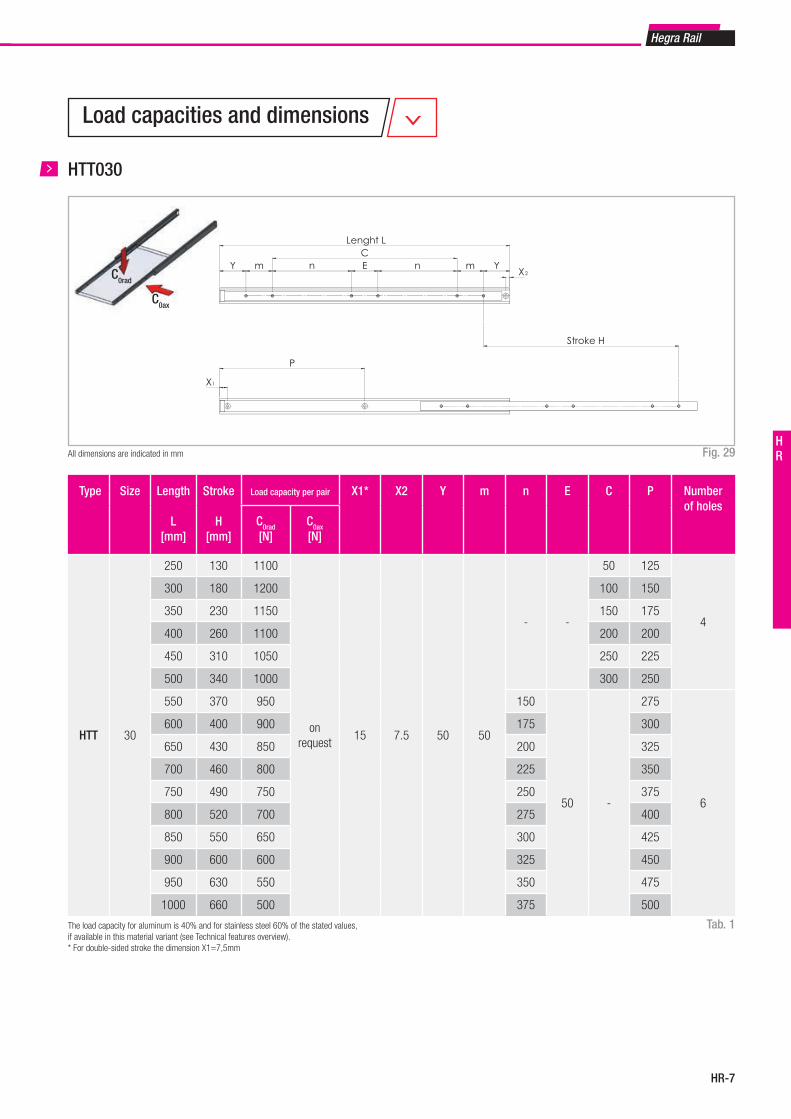
HR-7
Hegra Rail
HR
HTT030
Fig. 29
Tab. 1
All dimensions are indicated in mm
Type Size Length
L[mm]
Stroke
H[mm]
Load capacity per pair X1* X2 Y m n E C P Number of holes
C0rad
[N]C0ax
[N]
HTT 30
250 130 1100
on request
15 7.5 50 50
- -
50 125
4
300 180 1200 100 150
350 230 1150 150 175
400 260 1100 200 200
450 310 1050 250 225
500 340 1000 300 250
550 370 950 150
50 -
275
6
600 400 900 175 300
650 430 850 200 325
700 460 800 225 350
750 490 750 250 375
800 520 700 275 400
850 550 650 300 425
900 600 600 325 450
950 630 550 350 475
1000 660 500 375 500
The load capacity for aluminum is 40% and for stainless steel 60% of the stated values, if available in this material variant (see Technical features overview). * For double-sided stroke the dimension X1=7,5mm
Load capacities and dimensions
C0ax
C0rad
X
P
Lenght L
Y m n E n m YX
C
Stroke H
2
1
J BA
V
G
K
F
15
30
1
J = 16G = 10
HTT030-0550
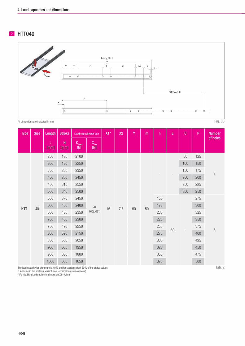
Hegra Rail
HR-8
Tab. 2
Type Size Length
L[mm]
Stroke
H[mm]
Load capacity per pair X1* X2 Y m n E C P Number of holes
C0rad
[N]C0ax
[N]
HTT 40
250 130 2100
on request
15 7.5 50 50
- -
50 125
4
300 180 2250 100 150
350 230 2350 150 175
400 260 2450 200 200
450 310 2550 250 225
500 340 2500 300 250
550 370 2450 150
50 -
275
6
600 400 2400 175 300
650 430 2350 200 325
700 460 2300 225 350
750 490 2250 250 375
800 520 2150 275 400
850 550 2050 300 425
900 600 1950 325 450
950 630 1800 350 475
1000 660 1650 375 500
The load capacity for aluminum is 40 % and for stainless steel 60 % of the stated values, if available in this material variant (see Technical features overview).* For double-sided stroke the dimension X1=7,5mm
HTT040
Fig. 30All dimensions are indicated in mm
4 Load capacities and dimensions
C0ax
C0radY m n E n m Y
X
CLength L
Stroke H
2
XP
1
J B
V
A
G
K
F
1
18,5
40
J = 25G = 12
HTT040-0550
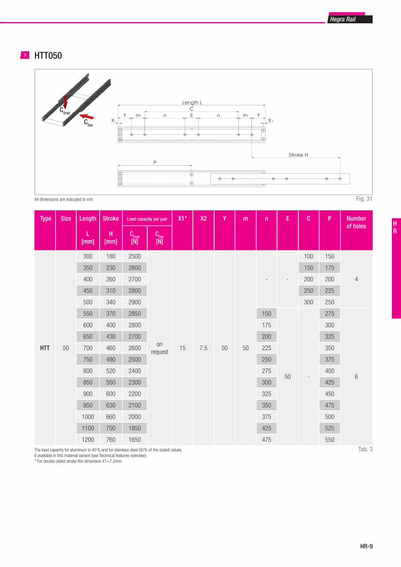
HR-9
Hegra Rail
HR
Type Size Length
L[mm]
Stroke
H[mm]
Load capacity per pair X1* X2 Y m n E C P Number of holes
C0rad
[N]C0ax
[N]
HTT 50
300 180 2500
on request
15 7.5 50 50
- -
100 150
4
350 230 2600 150 175
400 260 2700 200 200
450 310 2800 250 225
500 340 2900 300 250
550 370 2850 150
50 -
275
6
600 400 2800 175 300
650 430 2700 200 325
700 460 2600 225 350
750 490 2500 250 375
800 520 2400 275 400
850 550 2300 300 425
900 600 2200 325 450
950 630 2100 350 475
1000 660 2000 375 500
1100 700 1850 425 525
1200 760 1650 475 550
HTT050
Fig. 31All dimensions are indicated in mm
Tab. 3The load capacity for aluminum is 40 % and for stainless steel 60 % of the stated values, if available in this material variant (see Technical features overview).* For double-sided stroke the dimension X1=7,5mm
C0ax
C0rad
XY m n E n m Y
X
CLength L
Stroke H
1 2
P
J B
A
VD
K
G
F
1
18
60
J G J1 G1HTT050 30 12HTT060 40 12
HTT050-0550HTT060-0550

Hegra Rail
HR-10
4 Load capacities and dimensions
HTT
Fig. 32All dimensions are indicated in mm1 Mounting holes (V) for countersunk screws according to DIN 7991/ISO 10642
Type Size A B J G K D D1 F V1 Weight per single guide
[kg/m]
HTT
30 15 30 16 10 15-
-
M6 M5 2.4
40 18.5 40 2512
20M8 M6
4.3
50 19.5 50 30 12.5 25 5.6
X
P
Länge L
Y m n E n m YX
C
Hub H
2
1
J B
A
V
G
K
F
15
30
1
J = 16G = 10
HTT030-0550
Tab. 4
Y m n E n m YX
CLänge L
Hub H
2
XP
1
J B
V
A
GK
F
1
18,5
40
J = 25G = 12
HTT040-0550
XY m n E n m Y
X
CLänge L
Hub H
1 2
P
J B
A
VD
K
G
F
1
18
60
J G J1 G1HTT050 30 12HTT060 40 12
HTT050-0550HTT060-0550
HTT030 HTT040 HTT050
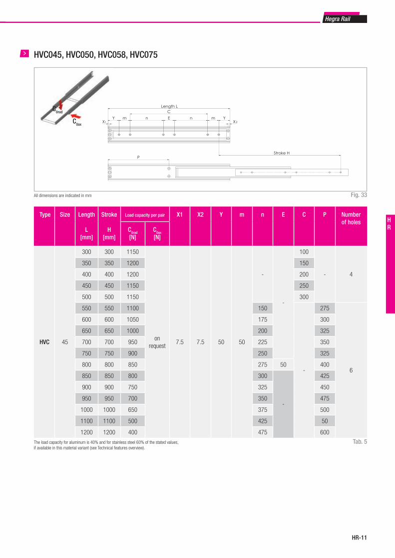
HR-11
Hegra Rail
HR
HVC045, HVC050, HVC058, HVC075
Fig. 33All dimensions are indicated in mm
Tab. 5
Type Size Length
L[mm]
Stroke
H[mm]
Load capacity per pair X1 X2 Y m n E C P Number of holes
C0rad
[N]C0ax
[N]
HVC 45
300 300 1150
on request
7.5 7.5 50 50
-
-
100
- 4
350 350 1200 150
400 400 1200 200
450 450 1150 250
500 500 1150 300
550 550 1100 150
-
275
6
600 600 1050 175 300
650 650 1000 200 325
700 700 950 225 350
750 750 900 250 325
800 800 850 275 50 400
850 850 800 300
-
425
900 900 750 325 450
950 950 700 350 475
1000 1000 650 375 500
1100 1100 500 425 50
1200 1200 400 475 600
The load capacity for aluminum is 40% and for stainless steel 60% of the stated values, if available in this material variant (see Technical features overview).
C0ax
C0rad
XX
Length L
Y m n E n m Y
C
Stroke H
1 2
P
D B
A
VK
J
G
F
1
26
75
J G J1 G1HVC045 16 10HVC050 20 12HVC058 25 12HVC075 30 12
HVC045-0550HVC050-0550HVC058-0550HVC075-0550
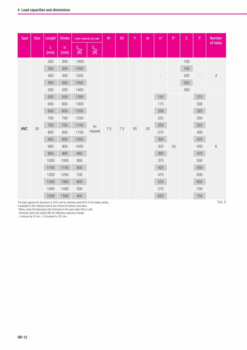
Hegra Rail
HR-12
4 Load capacities and dimensions
Tab. 6
Type Size Length
L[mm]
Stroke
H[mm]
Load capacity per pair X1 X2 Y m n* E* C P Number of holes
C0rad
[N]C0ax
[N]
HVC 50
300 300 1400
on request
7.5 7.5 50 50
- -
100
- 4
350 350 1450 150
400 400 1500 200
450 450 1450 250
500 500 1400 300
550 550 1350 150
50 -
275
6
600 600 1300 175 300
650 650 1250 200 325
700 700 1200 225 350
750 750 1150 250 325
800 800 1100 275 400
850 850 1050 300 425
900 900 1000 325 450
950 950 950 350 475
1000 1000 900 375 500
1100 1100 800 425 550
1200 1200 700 475 600
1300 1300 600 525 650
1400 1400 500 575 700
1500 1500 400 625 750
The load capacity for aluminum is 40 % and for stainless steel 60 % of the stated values, if available in this material variant (see Technical features overview). * When using full telescopes with interlocks in the open state (VO) or with interlocks open and closed (VB) the following measures change: n reduces by 35 mm - E increases to 120 mm.
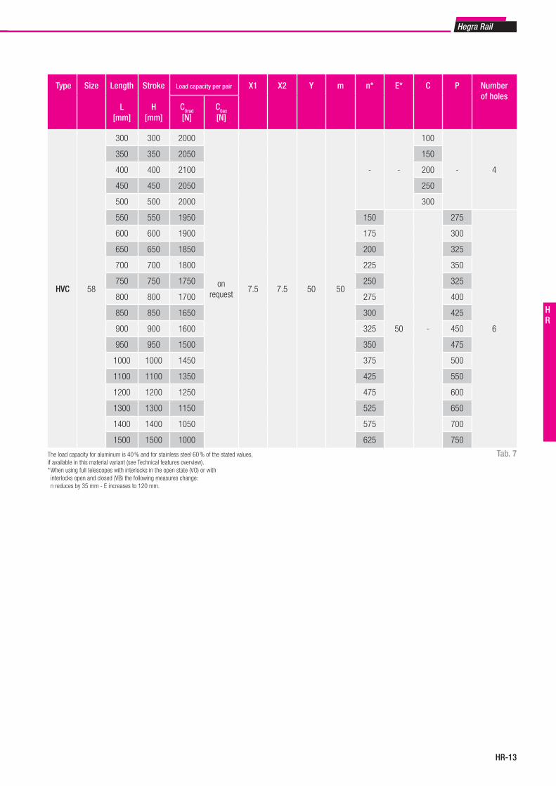
HR-13
Hegra Rail
HR
Tab. 7
Type Size Length
L[mm]
Stroke
H[mm]
Load capacity per pair X1 X2 Y m n* E* C P Number of holes
C0rad
[N]C0ax
[N]
HVC 58
300 300 2000
on request
7.5 7.5 50 50
- -
100
- 4
350 350 2050 150
400 400 2100 200
450 450 2050 250
500 500 2000 300
550 550 1950 150
50 -
275
6
600 600 1900 175 300
650 650 1850 200 325
700 700 1800 225 350
750 750 1750 250 325
800 800 1700 275 400
850 850 1650 300 425
900 900 1600 325 450
950 950 1500 350 475
1000 1000 1450 375 500
1100 1100 1350 425 550
1200 1200 1250 475 600
1300 1300 1150 525 650
1400 1400 1050 575 700
1500 1500 1000 625 750
The load capacity for aluminum is 40 % and for stainless steel 60 % of the stated values, if available in this material variant (see Technical features overview). * When using full telescopes with interlocks in the open state (VO) or with interlocks open and closed (VB) the following measures change: n reduces by 35 mm - E increases to 120 mm.
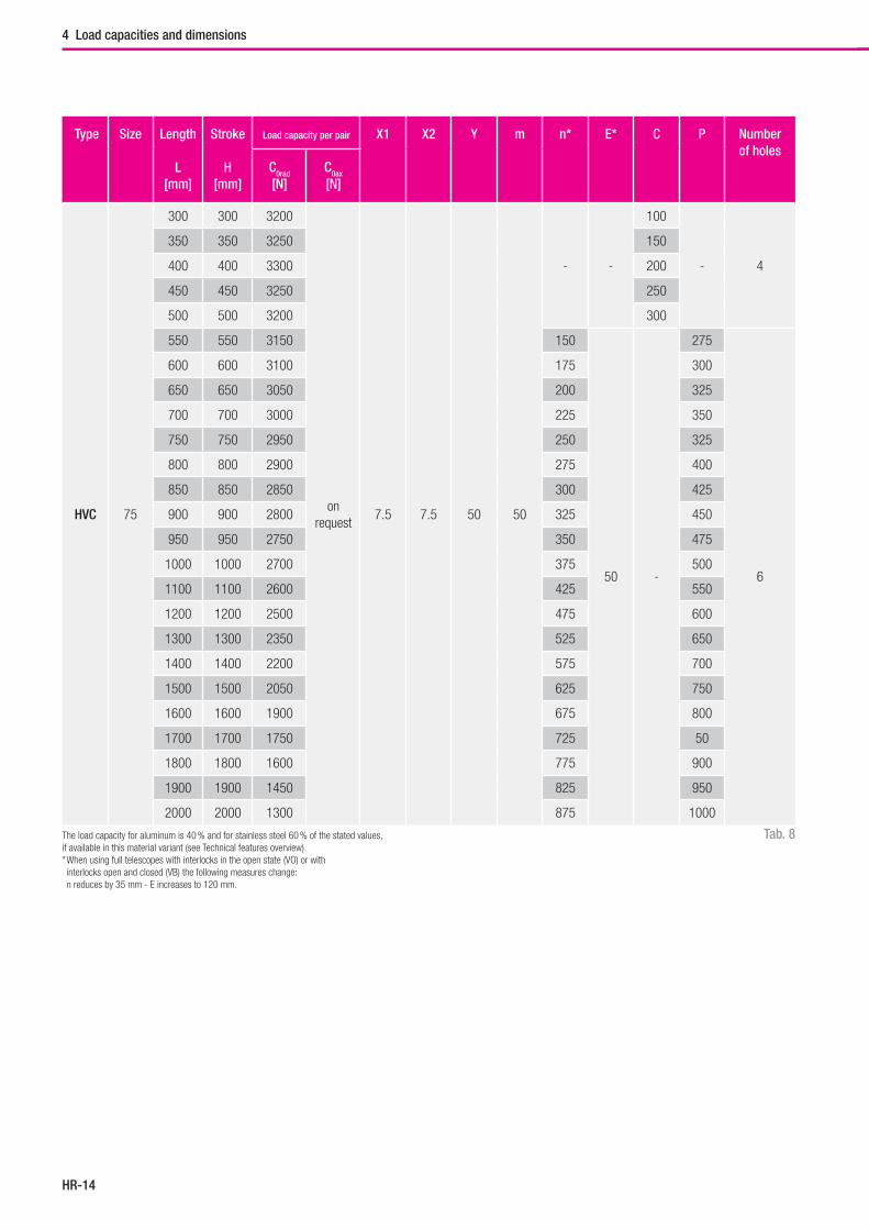
Hegra Rail
HR-14
4 Load capacities and dimensions
Tab. 8
Type Size Length
L[mm]
Stroke
H[mm]
Load capacity per pair X1 X2 Y m n* E* C P Number of holes
C0rad
[N]C0ax
[N]
HVC 75
300 300 3200
on request
7.5 7.5 50 50
- -
100
- 4
350 350 3250 150
400 400 3300 200
450 450 3250 250
500 500 3200 300
550 550 3150 150
50 -
275
6
600 600 3100 175 300
650 650 3050 200 325
700 700 3000 225 350
750 750 2950 250 325
800 800 2900 275 400
850 850 2850 300 425
900 900 2800 325 450
950 950 2750 350 475
1000 1000 2700 375 500
1100 1100 2600 425 550
1200 1200 2500 475 600
1300 1300 2350 525 650
1400 1400 2200 575 700
1500 1500 2050 625 750
1600 1600 1900 675 800
1700 1700 1750 725 50
1800 1800 1600 775 900
1900 1900 1450 825 950
2000 2000 1300 875 1000
The load capacity for aluminum is 40 % and for stainless steel 60 % of the stated values, if available in this material variant (see Technical features overview). * When using full telescopes with interlocks in the open state (VO) or with interlocks open and closed (VB) the following measures change: n reduces by 35 mm - E increases to 120 mm.
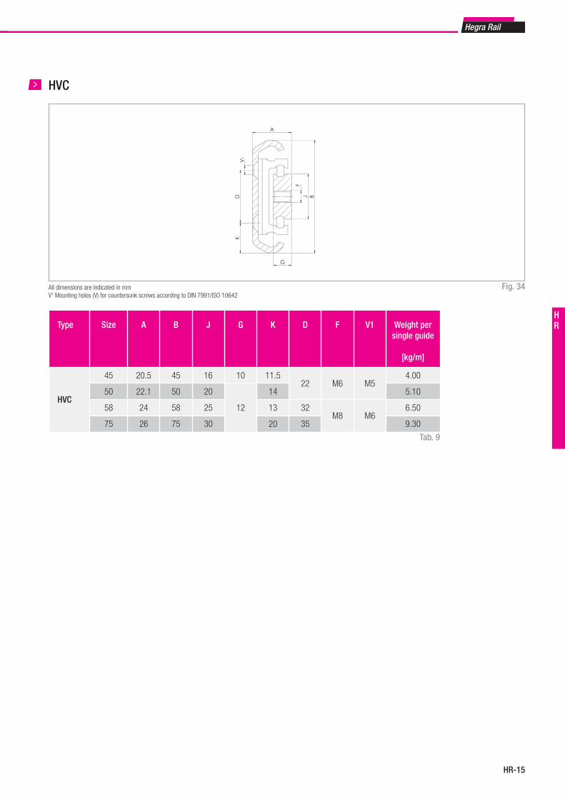
HR-15
Hegra Rail
HR
HVC
Fig. 34All dimensions are indicated in mmV1 Mounting holes (V) for countersunk screws according to DIN 7991/ISO 10642
Type Size A B J G K D F V1 Weight per single guide
[kg/m]
HVC
45 20.5 45 16 10 11.522 M6 M5
4.00
50 22.1 50 20
12
14 5.10
58 24 58 25 13 32M8 M6
6.50
75 26 75 30 20 35 9.30
Tab. 9
XX
Länge L
Y m n E n m Y
C
Hub H
1 2
P
D B
A
VK
J
G
F
1
26
75J G J1 G1
HVC045 16 10HVC050 20 12HVC058 25 12HVC075 30 12
HVC045-0550HVC050-0550HVC058-0550HVC075-0550
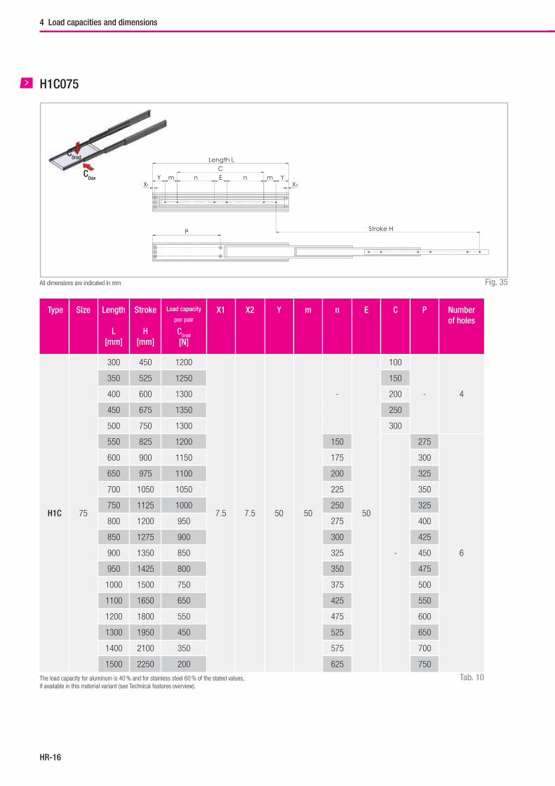
Hegra Rail
HR-16
4 Load capacities and dimensions
H1C075
Fig. 35All dimensions are indicated in mm
Tab. 10
Type Size Length
L[mm]
Stroke
H[mm]
Load capacity
per pair
C0rad
[N]
X1 X2 Y m n E C P Number of holes
H1C 75
300 450 1200
7.5 7.5 50 50
-
50
100
- 4
350 525 1250 150
400 600 1300 200
450 675 1350 250
500 750 1300 300
550 825 1200 150
-
275
6
600 900 1150 175 300
650 975 1100 200 325
700 1050 1050 225 350
750 1125 1000 250 325
800 1200 950 275 400
850 1275 900 300 425
900 1350 850 325 450
950 1425 800 350 475
1000 1500 750 375 500
1100 1650 650 425 550
1200 1800 550 475 600
1300 1950 450 525 650
1400 2100 350 575 700
1500 2250 200 625 750
The load capacity for aluminum is 40 % and for stainless steel 60 % of the stated values, if available in this material variant (see Technical features overview).
C0ax
C0rad
P
YX
m n E n m YX
CLength L
Stroke H
1 2
J B
G
AV
DK
F
1
30,1
75
J = 20G = 10
H1C075-0550
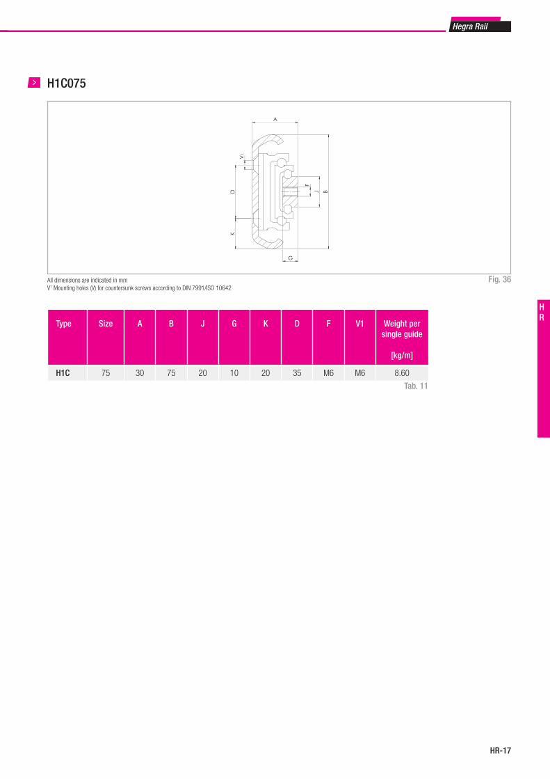
HR-17
Hegra Rail
HR
H1C075
Fig. 36All dimensions are indicated in mmV1 Mounting holes (V) for countersunk screws according to DIN 7991/ISO 10642
Type Size A B J G K D F V1 Weight per single guide
[kg/m]
H1C 75 30 75 20 10 20 35 M6 M6 8.60
Tab. 11
P
YX
m n E n m YX
CLänge L
Hub H
1 2
J B
G
A
V
DK
F
1
30,1
75
J = 20G = 10
H1C075-0550
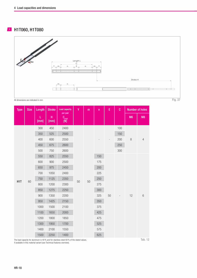
Hegra Rail
HR-18
4 Load capacities and dimensions
H1T060, H1T080
Fig. 37All dimensions are indicated in mm
Tab. 12
Type Size Length
L[mm]
Stroke
H[mm]
Load capacity
per pair
C0rad
[N]
Y m n E C Number of holes
M6 M8
H1T 60
300 450 2400
50 50
- -
100
8 4
350 525 2500 150
400 600 2550 200
450 675 2600 250
500 750 2600 300
550 825 2550 150
50 - 12 6
600 900 2500 175
650 975 2450 200
700 1050 2400 225
750 1125 2350 250
800 1200 2300 275
850 1275 2250 300
900 1350 2200 325
950 1425 2150 350
1000 1500 2100 375
1100 1650 2000 425
1200 1800 1850 475
1300 1950 1700 525
1400 2100 1550 575
1500 2250 1400 625
The load capacity for aluminum is 40 % and for stainless steel 60 % of the stated values, if available in this material variant (see Technical features overview).
C0axC0rad
m n
Y m n E n m Y
Length LC
Stroke H
J B
AK
DJ
GG
FF
1
1
144
80
J G J1 G1H1T060 25 12 40 10H1T080 30 12 50 12
H1T060-0550H1T080-1100
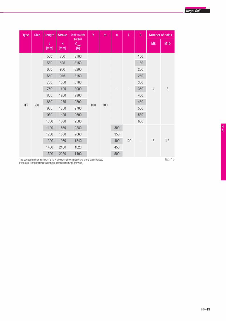
HR-19
Hegra Rail
HR
Tab. 13
Type Size Length
L[mm]
Stroke
H[mm]
Load capacity
per pair
C0rad
[N]
Y m n E C Number of holes
M8 M10
H1T 80
500 750 3100
100 100
- -
100
4 8
550 825 3150 150
600 900 3200 200
650 975 3150 250
700 1050 3100 300
750 1125 3000 350
800 1200 2900 400
850 1275 2800 450
900 1350 2700 500
950 1425 2600 550
1000 1500 2500 600
1100 1650 2280 300
100 - 6 12
1200 1800 2060 350
1300 1950 1840 400
1400 2100 1620 450
1500 2250 1400 500
The load capacity for aluminum is 40 % and for stainless steel 60 % of the stated values, if available in this material variant (see Technical features overview).
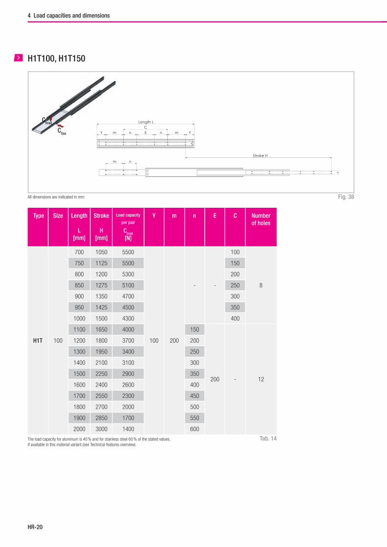
Hegra Rail
HR-20
4 Load capacities and dimensions
H1T100, H1T150
Fig. 38All dimensions are indicated in mm
Tab. 14
Type Size Length
L[mm]
Stroke
H[mm]
Load capacity
per pair
C0rad
[N]
Y m n E C Number of holes
H1T 100
700 1050 5500
100 200
- -
100
8
750 1125 5500 150
800 1200 5300 200
850 1275 5100 250
900 1350 4700 300
950 1425 4500 350
1000 1500 4300 400
1100 1650 4000 150
200 - 12
1200 1800 3700 200
1300 1950 3400 250
1400 2100 3100 300
1500 2250 2900 350
1600 2400 2600 400
1700 2550 2300 450
1800 2700 2000 500
1900 2850 1700 550
2000 3000 1400 600
The load capacity for aluminum is 40 % and for stainless steel 60 % of the stated values, if available in this material variant (see Technical features overview).
C0ax
C0rad
m n
Y m n E n m YC
Length L
Stroke H
D1
J B
A
GG
J D
F
F
1
1
1
49
100 J G J1 G1
H1T100 40 12 70 15H1T150 70 15 100 20
H1T100-1100H1T150-1100
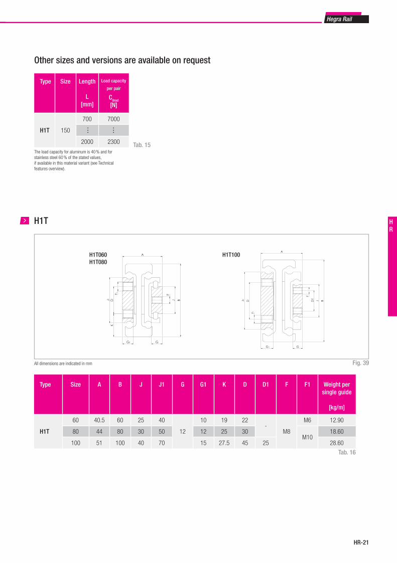
HR-21
Hegra Rail
HR
Other sizes and versions are available on request
Type Size Length
L[mm]
Load capacity
per pair
C0rad
[N]
H1T 150
700 7000
2000 2300
… …
Tab. 15The load capacity for aluminum is 40 % and for stainless steel 60 % of the stated values, if available in this material variant (see Technical features overview).
H1T
Fig. 39All dimensions are indicated in mm
Type Size A B J J1 G G1 K D D1 F F1 Weight per single guide
[kg/m]
H1T
60 40.5 60 25 40
12
10 19 22-
M8
M6 12.90
80 44 80 30 50 12 25 30M10
18.60
100 51 100 40 70 15 27.5 45 25 28.60
Tab. 16
m n
Y m n E n m Y
Länge LC
Hub H
J B
A
KDJ
GG
FF
1
1
1
44
80
J G J1 G1H1T060 25 12 40 10H1T080 30 12 50 12
H1T060-0550H1T080-1100
m n
Y m n E n m YC
Länge L
Hub H
D1
J B
A
GG
J D
F
F
1
1
1
49
100 J G J1 G1
H1T100 40 12 70 15H1T150 70 15 100 20
H1T100-1100H1T150-1100
H1T060H1T080
H1T100
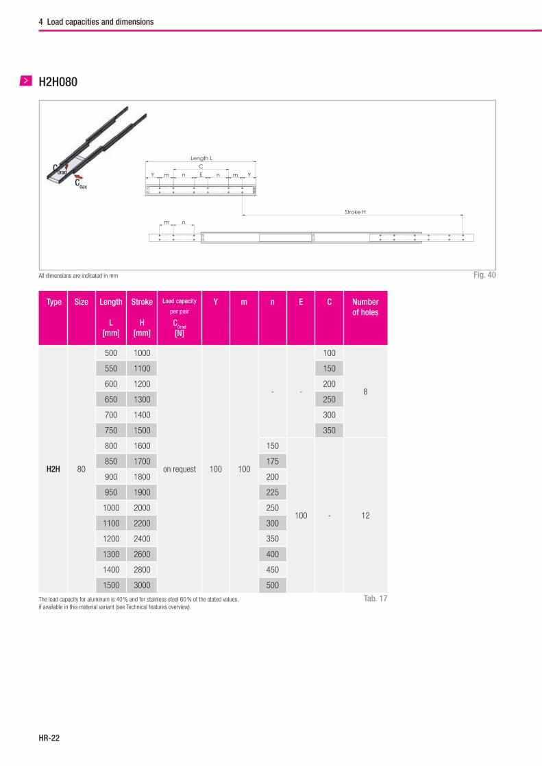
Hegra Rail
HR-22
4 Load capacities and dimensions
H2H080
Fig. 40All dimensions are indicated in mm
Tab. 17
Type Size Length
L[mm]
Stroke
H[mm]
Load capacity
per pair
C0rad
[N]
Y m n E C Number of holes
H2H 80
500 1000
on request 100 100
- -
100
8
550 1100 150
600 1200 200
650 1300 250
700 1400 300
750 1500 350
800 1600 150
100 - 12
850 1700 175
900 1800 200
950 1900 225
1000 2000 250
1100 2200 300
1200 2400 350
1300 2600 400
1400 2800 450
1500 3000 500
The load capacity for aluminum is 40 % and for stainless steel 60 % of the stated values, if available in this material variant (see Technical features overview).
C0ax
C0rad
m n
Y m n E n m Y
C
Length L
Stroke H
D J B
G
A
DJ
G
K
FF
7980
J = 50G = 15
H2D080-0800
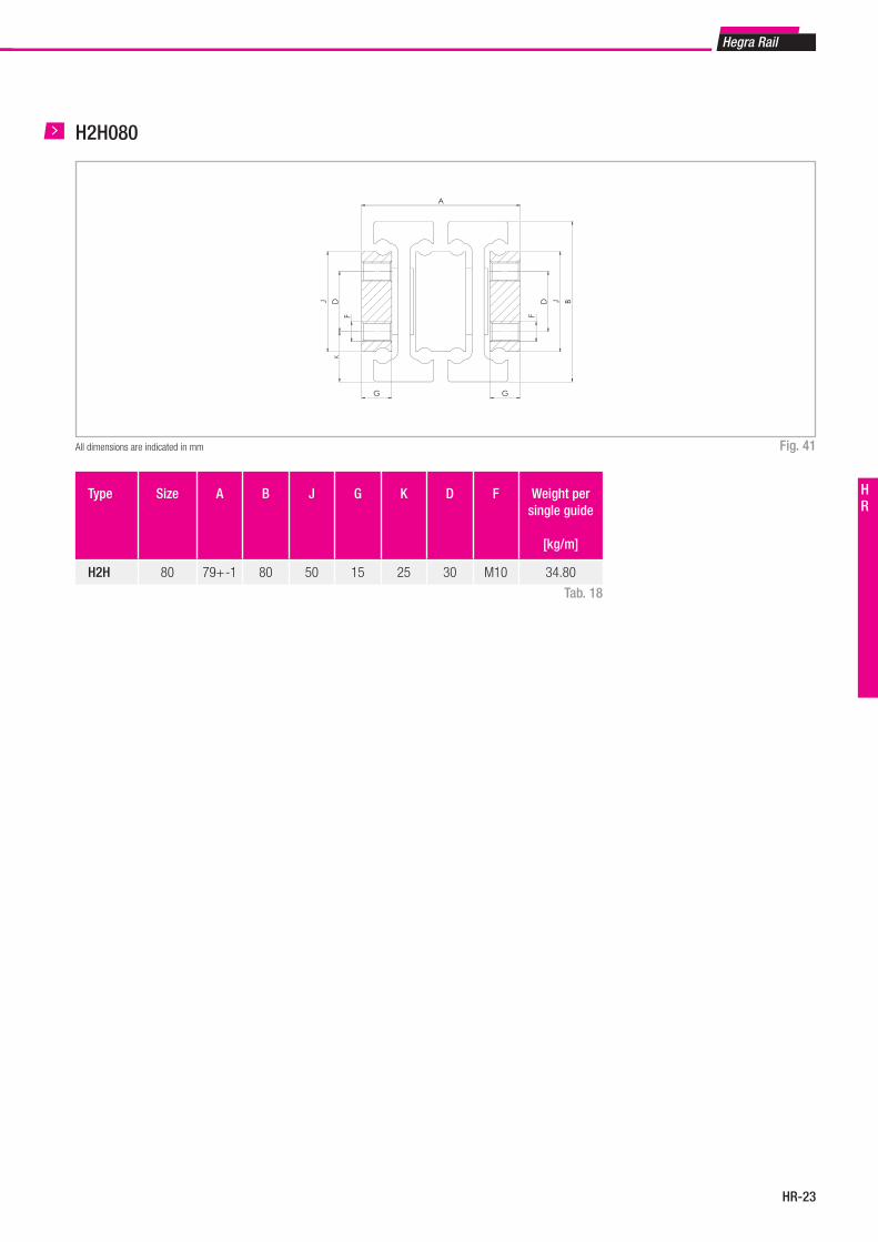
HR-23
Hegra Rail
HR
H2H080m n
Y m n E n m Y
C
Länge L
Hub H
D J B
G
A
DJ
G
K
FF
79
80J = 50G = 15
H2D080-0800
Fig. 41All dimensions are indicated in mm
Type Size A B J G K D F Weight per single guide
[kg/m]
H2H 80 79+-1 80 50 15 25 30 M10 34.80
Tab. 18
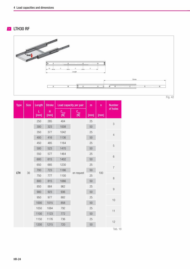
Hegra Rail
HR-24
C0radC0rad
LTH30 RF
Fig. 42
Tab. 19
Type Size Length
L[mm]
Stroke
H[mm]
Load capacity per pair m
[mm]
n
[mm]
Numberof holes
C0rad
[N]C0ax
[N]
LTH 30
250 285 404
on request
25
100
3300 323 1008 50
350 377 1042 254
400 416 1136 50
450 485 1164 255
500 523 1470 50
550 577 1464 256
600 615 1402 50
650 685 1230 257
700 723 1186 50
750 777 1100 258
800 815 1066 50
850 884 962 259
900 923 936 50
950 977 882 2510
1000 1015 858 50
1050 1084 792 2511
1100 1123 772 50
1150 1176 736 2512
1200 1215 720 50
Stroke
Length
m n n n
B
A
F
4 Load capacities and dimensions
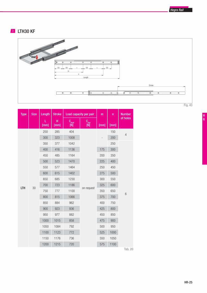
HR-25
Hegra Rail
HR
LTH30 KF
Fig. 43
Stroke
Length
50 50 = 50 = 50
m
n
B
A
F
Tab. 20
Type Size Length
L[mm]
Stroke
H[mm]
Load capacity per pair m
[mm]
n
[mm]
Numberof holes
C0rad
[N]C0ax
[N]
LTH 30
250 285 404
on request
-
1504
300 323 1008 200
350 377 1042 250
6
400 416 1136 175 300
450 485 1164 200 350
500 523 1470 225 400
550 577 1464 250 450
600 615 1402 275 500
650 685 1230 300 550
700 723 1186 325 600
750 777 1100 350 650
800 815 1066 375 700
850 884 962 400 750
900 923 936 425 800
950 977 882 450 850
1000 1015 858 475 900
1050 1084 792 500 950
1100 1123 772 525 1000
1150 1176 736 550 1050
1200 1215 720 575 1100
C0radC0rad
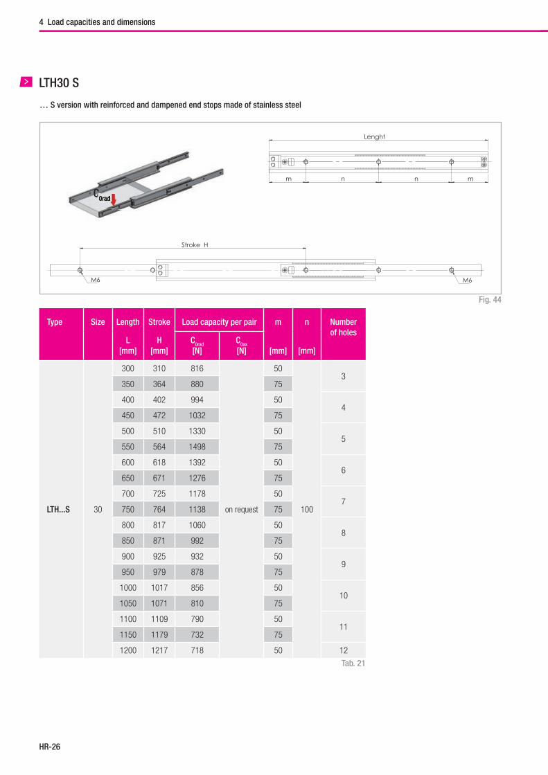
Hegra Rail
HR-26
Type Size Length
L[mm]
Stroke
H[mm]
Load capacity per pair m
[mm]
n
[mm]
Numberof holes
C0rad
[N]C0ax
[N]
LTH...S 30
300 310 816
on request
50
100
3350 364 880 75
400 402 994 504
450 472 1032 75
500 510 1330 505
550 564 1498 75
600 618 1392 506
650 671 1276 75
700 725 1178 507
750 764 1138 75
800 817 1060 508
850 871 992 75
900 925 932 509
950 979 878 75
1000 1017 856 5010
1050 1071 810 75
1100 1109 790 5011
1150 1179 732 75
1200 1217 718 50 12
Tab. 21
LTH30 S
… S version with reinforced and dampened end stops made of stainless steel
Stroke H
M6 M6
Lenght
m n m n
F
A
B
Fig. 44
4 Load capacities and dimensions
C0radC0rad
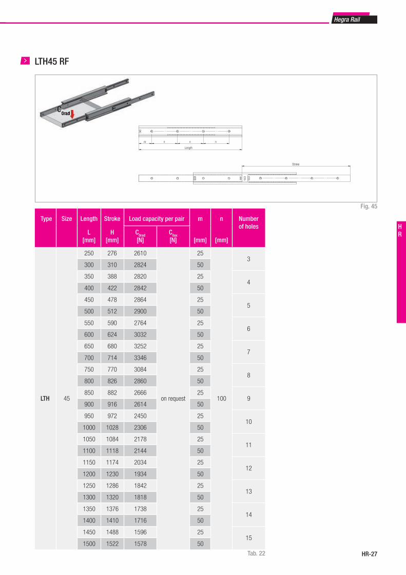
HR-27
Hegra Rail
HR
Type Size Length
L[mm]
Stroke
H[mm]
Load capacity per pair m
[mm]
n
[mm]
Numberof holes
C0rad
[N]C0ax
[N]
LTH 45
250 276 2610
on request
25
100
3300 310 2824 50
350 388 2820 254
400 422 2842 50
450 478 2864 255
500 512 2900 50
550 590 2764 256
600 624 3032 50
650 680 3252 257
700 714 3346 50
750 770 3084 258
800 826 2860 50
850 882 2666 259
900 916 2614 50
950 972 2450 2510
1000 1028 2306 50
1050 1084 2178 2511
1100 1118 2144 50
1150 1174 2034 2512
1200 1230 1934 50
1250 1286 1842 2513
1300 1320 1818 50
1350 1376 1738 2514
1400 1410 1716 50
1450 1488 1596 2515
1500 1522 1578 50
Tab. 22
LTH45 RF
Stroke
m n n n
Length
B
A
F
Fig. 45
C0radC0rad
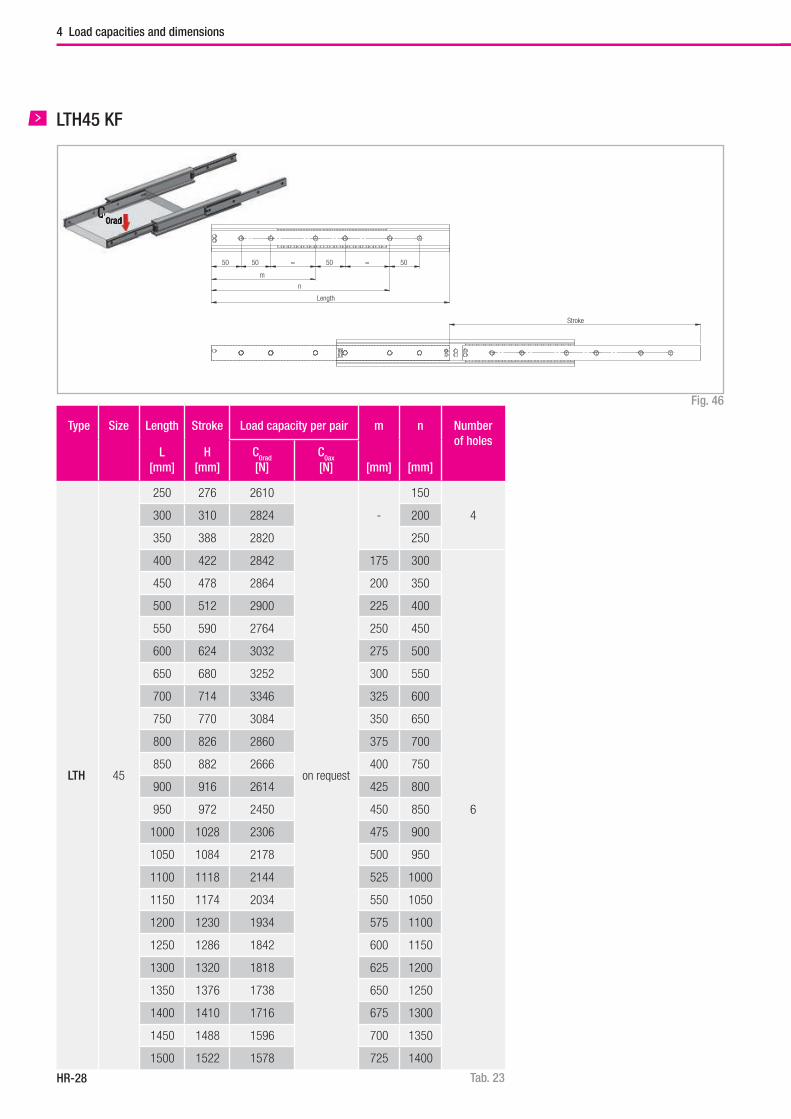
Hegra Rail
HR-28
Type Size Length
L[mm]
Stroke
H[mm]
Load capacity per pair m
[mm]
n
[mm]
Numberof holes
C0rad
[N]C0ax
[N]
LTH 45
250 276 2610
on request
-
150
4300 310 2824 200
350 388 2820 250
400 422 2842 175 300
6
450 478 2864 200 350
500 512 2900 225 400
550 590 2764 250 450
600 624 3032 275 500
650 680 3252 300 550
700 714 3346 325 600
750 770 3084 350 650
800 826 2860 375 700
850 882 2666 400 750
900 916 2614 425 800
950 972 2450 450 850
1000 1028 2306 475 900
1050 1084 2178 500 950
1100 1118 2144 525 1000
1150 1174 2034 550 1050
1200 1230 1934 575 1100
1250 1286 1842 600 1150
1300 1320 1818 625 1200
1350 1376 1738 650 1250
1400 1410 1716 675 1300
1450 1488 1596 700 1350
1500 1522 1578 725 1400
Tab. 23
LTH45 KF
Fig. 46
Stroke
50 50 = 50 = 50
m
n
Length
B
A
F
4 Load capacities and dimensions
C0radC0rad
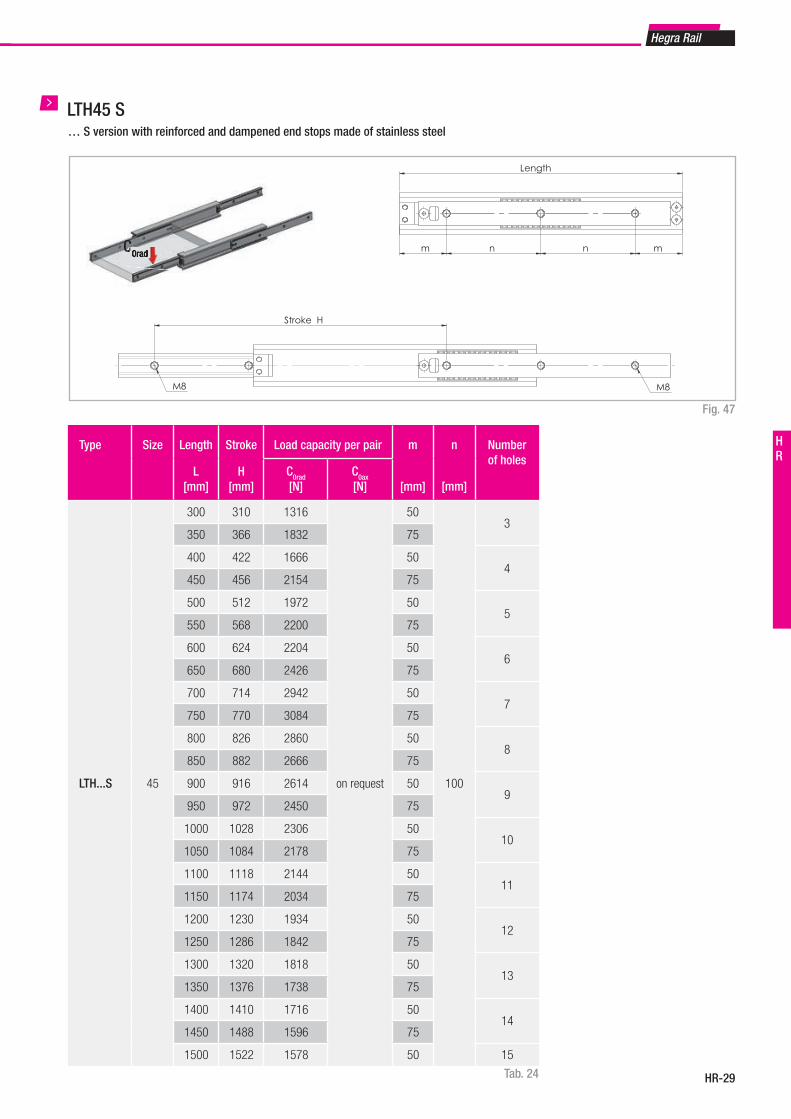
HR-29
Hegra Rail
HR
LTH45 S
Fig. 47
Tab. 24
Type Size Length
L[mm]
Stroke
H[mm]
Load capacity per pair m
[mm]
n
[mm]
Numberof holes
C0rad
[N]C0ax
[N]
LTH...S 45
300 310 1316
on request
50
100
3350 366 1832 75
400 422 1666 504
450 456 2154 75
500 512 1972 505
550 568 2200 75
600 624 2204 506
650 680 2426 75
700 714 2942 507
750 770 3084 75
800 826 2860 508
850 882 2666 75
900 916 2614 509
950 972 2450 75
1000 1028 2306 5010
1050 1084 2178 75
1100 1118 2144 5011
1150 1174 2034 75
1200 1230 1934 5012
1250 1286 1842 75
1300 1320 1818 5013
1350 1376 1738 75
1400 1410 1716 5014
1450 1488 1596 75
1500 1522 1578 50 15
Length
n m m n
Stroke H
M8 M8
A B
F
… S version with reinforced and dampened end stops made of stainless steel
C0radC0rad
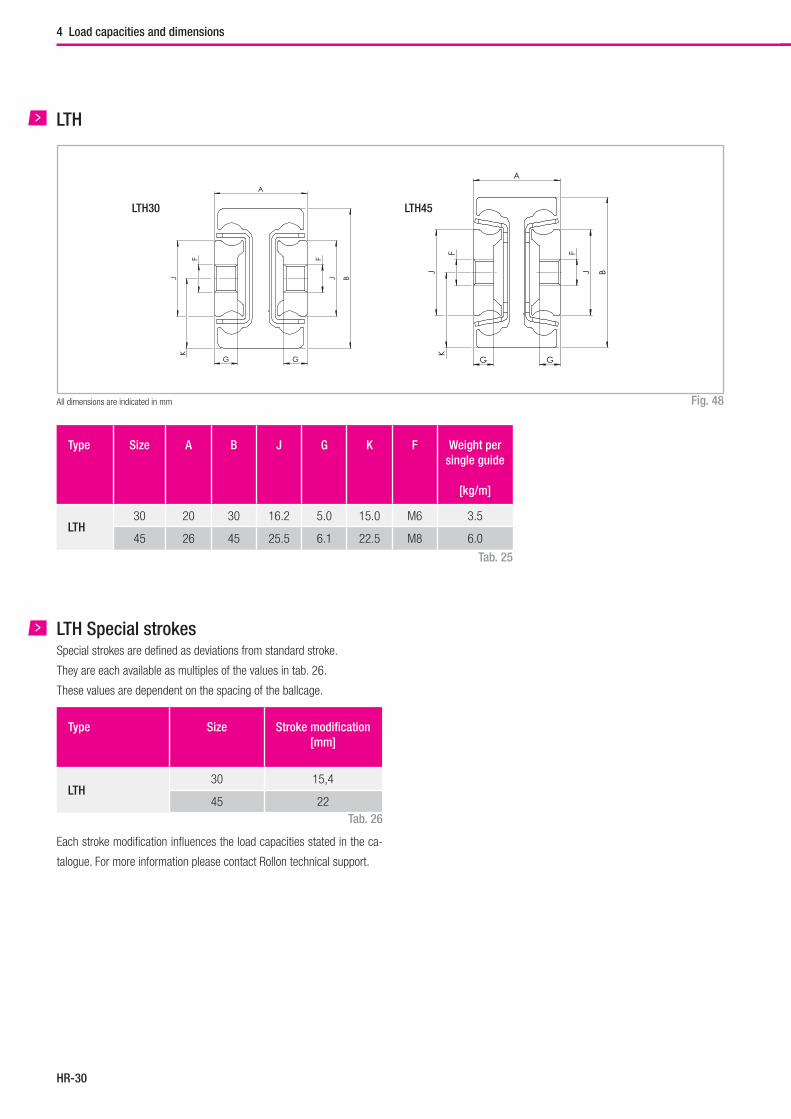
Hegra Rail
HR-30
4 Load capacities and dimensions
A
B
J
G G
J
K
F
F
LTH
Fig. 48All dimensions are indicated in mm
A
B
J
G G
J
K
F
F
Type Size A B J G K F Weight per single guide
[kg/m]
LTH30 20 30 16.2 5.0 15.0 M6 3.5
45 26 45 25.5 6.1 22.5 M8 6.0
Tab. 25
LTH30 LTH45
Type Size Stroke modification [mm]
LTH30 15,4
45 22
LTH Special strokesSpecial strokes are defined as deviations from standard stroke.
They are each available as multiples of the values in tab. 26.
These values are dependent on the spacing of the ballcage.
Tab. 26
Each stroke modification influences the load capacities stated in the ca-
talogue. For more information please contact Rollon technical support.
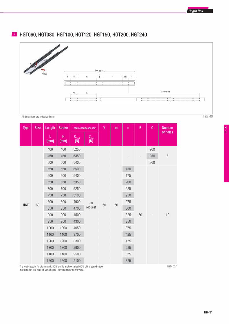
HR-31
Hegra Rail
HR
HGT060, HGT080, HGT100, HGT120, HGT150, HGT200, HGT240
Fig. 49All dimensions are indicated in mm
Tab. 27
Type Size Length
L[mm]
Stroke
H[mm]
Load capacity per pair Y m n E C Number of holes
C0rad
[N]C0ax
[N]
HGT 60
400 400 5250
on request
50 50
- -
200
8450 450 5350 250
500 500 5400 300
550 550 5500 150
50 - 12
600 600 5400 175
650 650 5350 200
700 700 5250 225
750 750 5100 250
800 800 4900 275
850 850 4700 300
900 900 4500 325
950 950 4300 350
1000 1000 4050 375
1100 1100 3700 425
1200 1200 3300 475
1300 1300 2900 525
1400 1400 2500 575
1500 1500 2100 625
The load capacity for aluminum is 40 % and for stainless steel 60 % of the stated values, if available in this material variant (see Technical features overview).
C0ax
C0rad
m n
Y m n E n m YC
Length L
Stroke H
D J BDJ
GG
AK
FF
HGT060-0550HGT070-0550HGT080-1100HGT100-1100HGT120-1100HGT150-1100HGT200-1100HGT240-1100
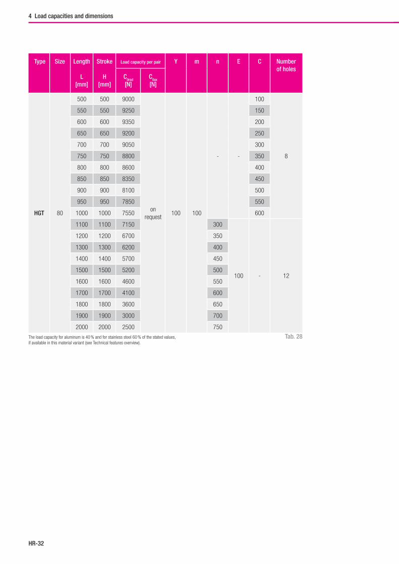
Hegra Rail
HR-32
4 Load capacities and dimensions
Tab. 28
Type Size Length
L[mm]
Stroke
H[mm]
Load capacity per pair Y m n E C Number of holes
C0rad
[N]C0ax
[N]
HGT 80
500 500 9000
on request
100 100
- -
100
8
550 550 9250 150
600 600 9350 200
650 650 9200 250
700 700 9050 300
750 750 8800 350
800 800 8600 400
850 850 8350 450
900 900 8100 500
950 950 7850 550
1000 1000 7550 600
1100 1100 7150 300
100 - 12
1200 1200 6700 350
1300 1300 6200 400
1400 1400 5700 450
1500 1500 5200 500
1600 1600 4600 550
1700 1700 4100 600
1800 1800 3600 650
1900 1900 3000 700
2000 2000 2500 750
The load capacity for aluminum is 40 % and for stainless steel 60 % of the stated values, if available in this material variant (see Technical features overview).
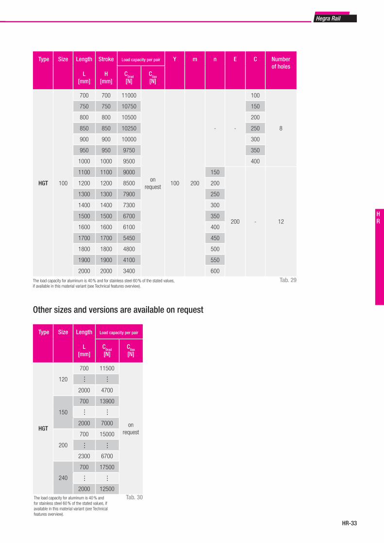
HR-33
Hegra Rail
HR
Tab. 29
Type Size Length
L[mm]
Stroke
H[mm]
Load capacity per pair Y m n E C Number of holes
C0rad
[N]C0ax
[N]
HGT 100
700 700 11000
on request
100 200
- -
100
8
750 750 10750 150
800 800 10500 200
850 850 10250 250
900 900 10000 300
950 950 9750 350
1000 1000 9500 400
1100 1100 9000 150
200 - 12
1200 1200 8500 200
1300 1300 7900 250
1400 1400 7300 300
1500 1500 6700 350
1600 1600 6100 400
1700 1700 5450 450
1800 1800 4800 500
1900 1900 4100 550
2000 2000 3400 600
The load capacity for aluminum is 40 % and for stainless steel 60 % of the stated values, if available in this material variant (see Technical features overview).
Other sizes and versions are available on request
Type Size Length
L[mm]
Load capacity per pair
C0rad
[N]C0ax
[N]
HGT
120
700 11500
on request
2000 4700
150
700 13900
2000 7000
200
700 15000
2300 6700
240
700 17500
2000 12500
… …
… …
……
……
Tab. 30The load capacity for aluminum is 40 % and for stainless steel 60 % of the stated values, if available in this material variant (see Technical features overview).
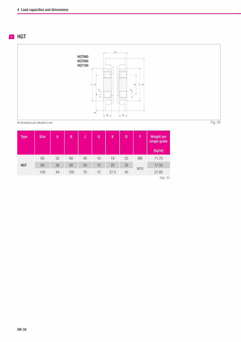
Hegra Rail
HR-34
4 Load capacities and dimensions
HGT
Fig. 50All dimensions are indicated in mm
Type Size A B J G K D F Weight per single guide
[kg/m]
HGT
60 32 60 40 10 19 22 M6 11.70
80 36 80 50 12 25 30M10
17.50
100 44 100 70 15 27.5 45 27.60
Tab. 31
m n
Y m n E n m YC
Länge L
Hub H
D J BDJ
GG
A
K
FF
80
36
J G J1 G1HGT060 40 10HGT070 45 12HGT080 50 12HGT100 70 15HGT120 80 15HGT150 100 20HGT200 140 25HGT240 180 25
HGT060-0550HGT070-0550HGT080-1100HGT100-1100HGT120-1100HGT150-1100HGT200-1100HGT240-1100
HGT060HGT080HGT100
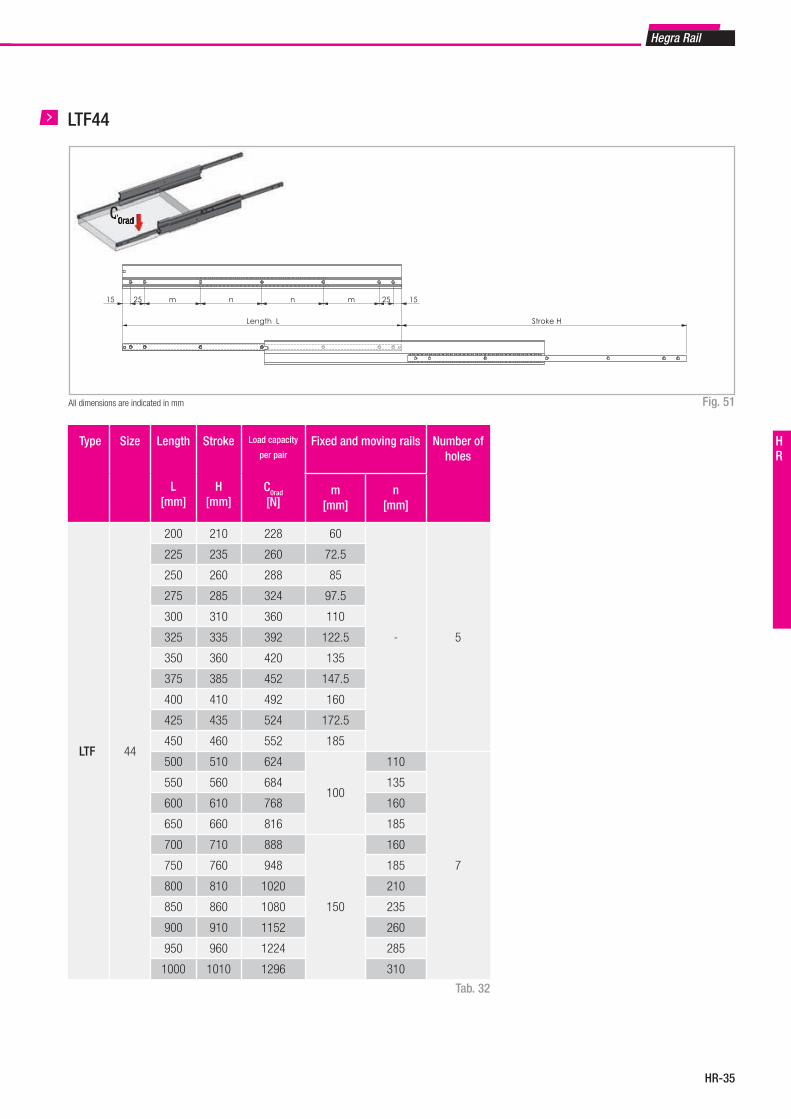
HR-35
Hegra Rail
HR
LTF44
Fig. 51All dimensions are indicated in mm
Length L Stroke H
15 25 m n n m 25 15
Tab. 32
Type Size Length
L[mm]
Stroke
H[mm]
Load capacity
per pair
C0rad
[N]
Fixed and moving rails Number of holes
m[mm]
n[mm]
LTF 44
200 210 228 60
- 5
225 235 260 72.5
250 260 288 85
275 285 324 97.5
300 310 360 110
325 335 392 122.5
350 360 420 135
375 385 452 147.5
400 410 492 160
425 435 524 172.5
450 460 552 185
500 510 624
100
110
7
550 560 684 135
600 610 768 160
650 660 816 185
700 710 888
150
160
750 760 948 185
800 810 1020 210
850 860 1080 235
900 910 1152 260
950 960 1224 285
1000 1010 1296 310
C0radC0rad
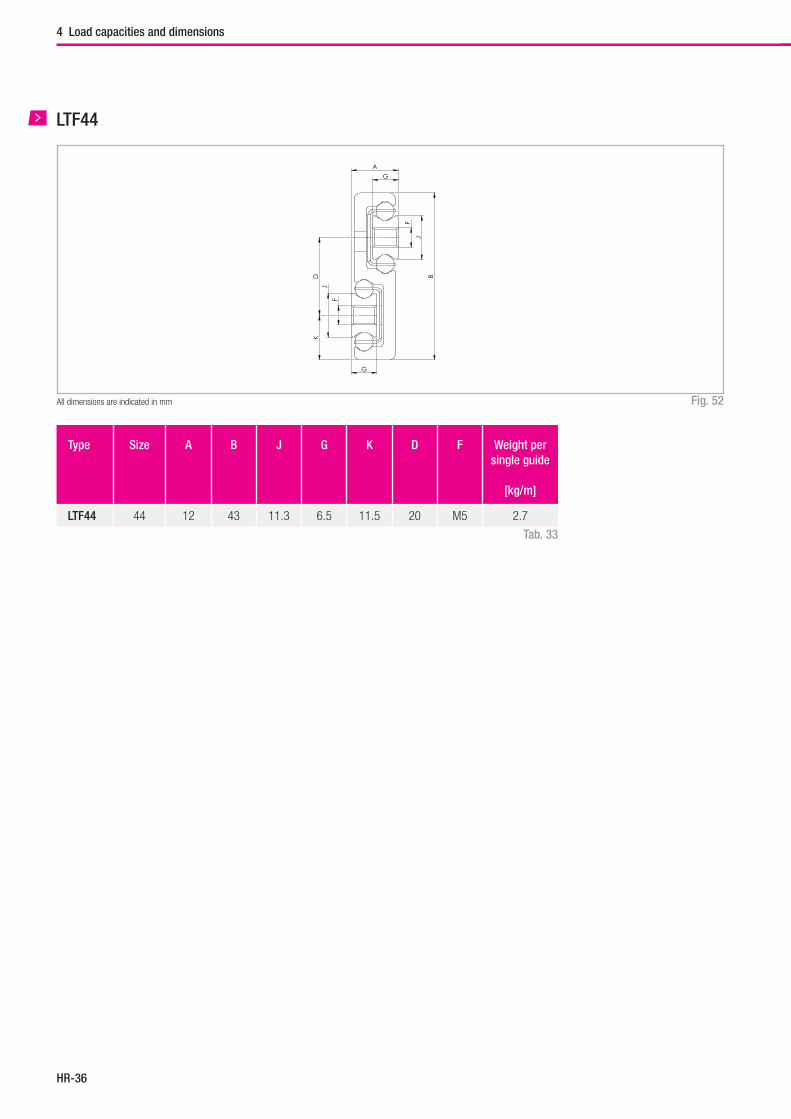
Hegra Rail
HR-36
4 Load capacities and dimensions
Fig. 52All dimensions are indicated in mm
Type Size A B J G K D F Weight per single guide
[kg/m]
LTF44 44 12 43 11.3 6.5 11.5 20 M5 2.7
Tab. 33
LTF44
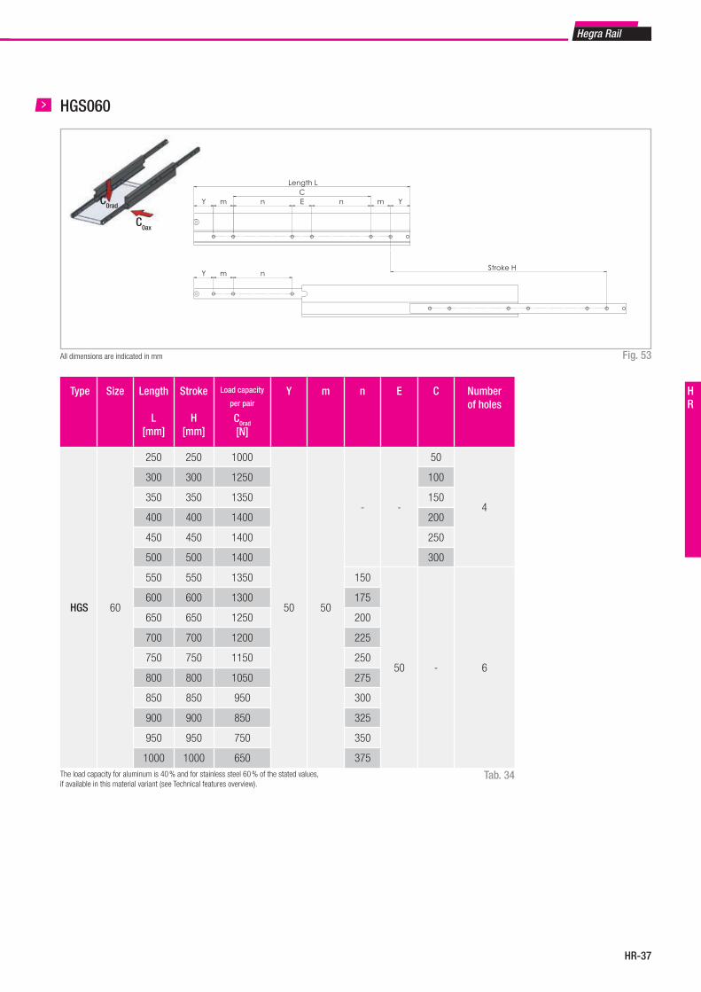
HR-37
Hegra Rail
HR
HGS060
Fig. 53All dimensions are indicated in mm
Type Size Length
L[mm]
Stroke
H[mm]
Load capacity
per pair
C0rad
[N]
Y m n E C Number of holes
HGS 60
250 250 1000
50 50
- -
50
4
300 300 1250 100
350 350 1350 150
400 400 1400 200
450 450 1400 250
500 500 1400 300
550 550 1350 150
50 - 6
600 600 1300 175
650 650 1250 200
700 700 1200 225
750 750 1150 250
800 800 1050 275
850 850 950 300
900 900 850 325
950 950 750 350
1000 1000 650 375
Tab. 34The load capacity for aluminum is 40 % and for stainless steel 60 % of the stated values, if available in this material variant (see Technical features overview).
C0ax
C0rad
Y m n
Y m n E n m YC
Length L
Stroke H
KD
J
J
G
G
A
B
F
F
22
80
J G J1 G1HGS045 12 8HGS060 16 10HGS080 25 12HGS100 32 12HGS120 40 15HGS150 50 15
HGS045-0550HGS060-0550HGS080-0550HGS100-0550HGS120-0550HGS150-0550
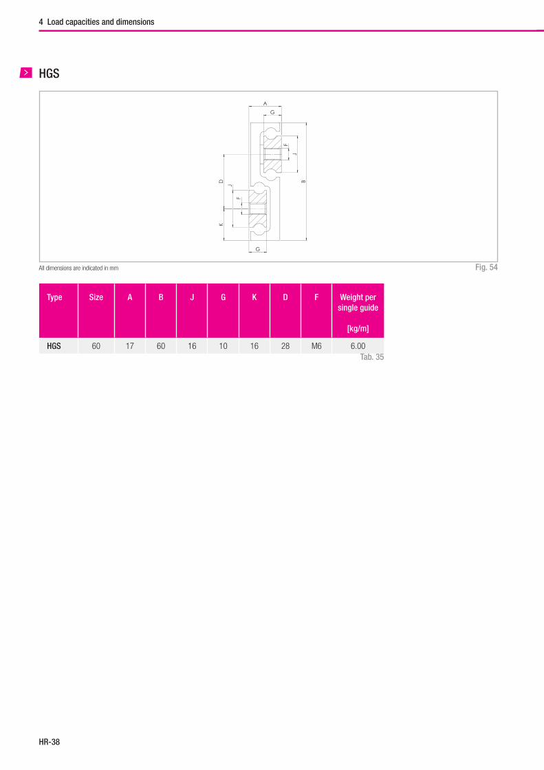
Hegra Rail
HR-38
4 Load capacities and dimensions
HGS
Fig. 54All dimensions are indicated in mm
Type Size A B J G K D F Weight per single guide
[kg/m]
HGS 60 17 60 16 10 16 28 M6 6.00Tab. 35
Y m n
Y m n E n m YC
Länge L
Hub H
KD
J
J
G
G
A
B
F
F
22
80
J G J1 G1HGS045 12 8HGS060 16 10HGS080 25 12HGS100 32 12HGS120 40 15HGS150 50 15
HGS045-0550HGS060-0550HGS080-0550HGS100-0550HGS120-0550HGS150-0550
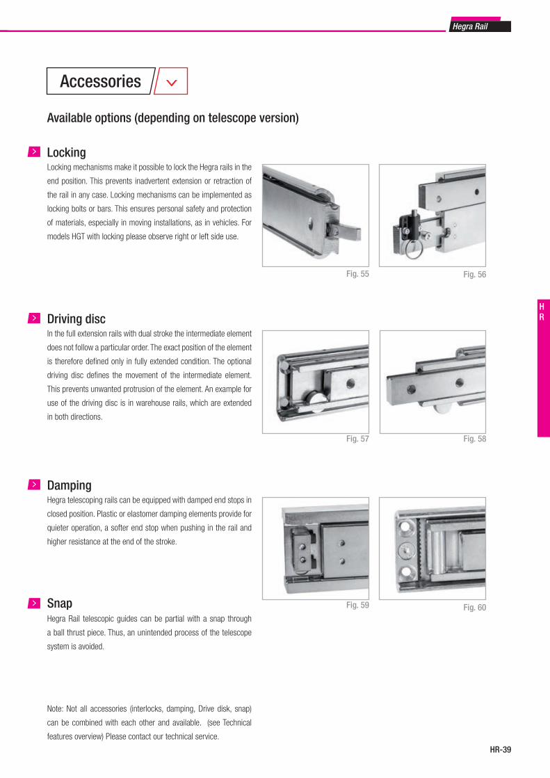
HR-39
Hegra Rail
HR
Available options (depending on telescope version)
Locking mechanisms make it possible to lock the Hegra rails in the
end position. This prevents inadvertent extension or retraction of
the rail in any case. Locking mechanisms can be implemented as
locking bolts or bars. This ensures personal safety and protection
of materials, especially in moving installations, as in vehicles. For
models HGT with locking please observe right or left side use.
Locking
Fig. 55 Fig. 56
In the full extension rails with dual stroke the intermediate element
does not follow a particular order. The exact position of the element
is therefore defi ned only in fully extended condition. The optional
driving disc defi nes the movement of the intermediate element.
This prevents unwanted protrusion of the element. An example for
use of the driving disc is in warehouse rails, which are extended
in both directions.
Driving disc
Fig. 57
Hegra telescoping rails can be equipped with damped end stops in
closed position. Plastic or elastomer damping elements provide for
quieter operation, a softer end stop when pushing in the rail and
higher resistance at the end of the stroke.
Damping
Fig. 59 Fig. 60
Fig. 58
Accessories
Note: Not all accessories (interlocks, damping, Drive disk, snap)
can be combined with each other and available. (see Technical
features overview) Please contact our technical service.
Hegra Rail telescopic guides can be partial with a snap through
a ball thrust piece. Thus, an unintended process of the telescope
system is avoided.
Snap
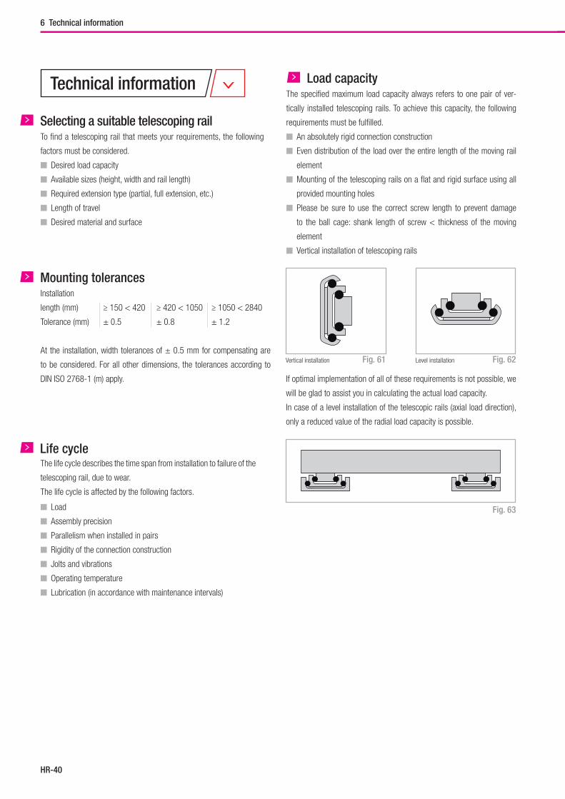
Hegra Rail
HR-40
6 Technical information
Mounting tolerancesInstallation
length (mm) ≥ 150 < 420 ≥ 420 < 1050 ≥ 1050 < 2840
Tolerance (mm) ± 0.5 ± 0.8 ± 1.2
At the installation, width tolerances of ± 0.5 mm for compensating are
to be considered. For all other dimensions, the tolerances according to
DIN ISO 2768-1 (m) apply.
Load capacityThe specified maximum load capacity always refers to one pair of ver-
tically installed telescoping rails. To achieve this capacity, the following
requirements must be fulfilled.
� An absolutely rigid connection construction
� Even distribution of the load over the entire length of the moving rail
element
� Mounting of the telescoping rails on a flat and rigid surface using all
provided mounting holes
� Please be sure to use the correct screw length to prevent damage
to the ball cage: shank length of screw < thickness of the moving
element
� Vertical installation of telescoping rails
Vertical installation Level installation
If optimal implementation of all of these requirements is not possible, we
will be glad to assist you in calculating the actual load capacity.
In case of a level installation of the telescopic rails (axial load direction),
only a reduced value of the radial load capacity is possible.
Life cycleThe life cycle describes the time span from installation to failure of the
telescoping rail, due to wear.
The life cycle is affected by the following factors.
� Load
� Assembly precision
� Parallelism when installed in pairs
� Rigidity of the connection construction
� Jolts and vibrations
� Operating temperature
� Lubrication (in accordance with maintenance intervals)
Fig. 61 Fig. 62
Fig. 63
Selecting a suitable telescoping railTo find a telescoping rail that meets your requirements, the following
factors must be considered.
� Desired load capacity
� Available sizes (height, width and rail length)
� Required extension type (partial, full extension, etc.)
� Length of travel
� Desired material and surface
Technical information
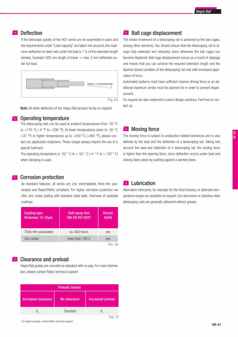
HR-41
Hegra Rail
HR
Coating typethickness 12-15μm
Salt-spray test DIN EN ISO 9227
Reach/RoHS
Thick-film passivated ca. 400 hours yes
Zinc nickel more than 700 h yes
Tab. 36
Fig. 64
DeflectionIf the telescopic guides of the HGT series are be assembled in pairs and
the requirements under “Load capacity” are taken into account, the maxi-
mum deflection of steel rails under full load is 1 % of the extended length
(stroke). Example: 500 mm length of travel -> max. 5 mm deflection un-
der full load.
Deflection ≈ 1 % of the extended length
Operating temperatureThe telescoping rails can be used at ambient temperatures from -20 °C
to +170 °C (-4 °F to +338 °F). At lower temperatures down to -30 °C
( -22 °F) or higher temperatures up to +250 °C (+482 °F), please con-
tact our application engineers. These ranges always require the use of a
special lubricant.
The operating temperature is -20 ° C to + 50 ° C (-4 ° F to + 122 ° F)
when damping is used.
Corrosion protectionAs standard features, all series are zinc electroplated, thick-film pas-
sivated and Reach/RoHs compliant. For higher corrosion protection we
offer zinc nickel plating with stainless steel balls. Overview of available
coatings:
Ball cage displacementThe stroke movement of a telescoping rail is achieved by the ball cages,
among other elements. You should ensure that the telescoping rail is al-
ways fully extended and retracted, since otherwise the ball cages can
become displaced. Ball cage displacement occurs as a result of slippage
and means that you can achieve the required extension length and the
desired closed condition of the telescoping rail only with increased appli-
cation of force.
Automated systems must have sufficient reserve driving force or an ad-
ditional maximum stroke must be planned for in order to prevent displa-
cement.
On request we also implement custom design solutions. Feel free to con-
tact us.
Moving forceThe moving force is subject to production-related tolerances and is also
defined by the load and the deflection of a telescoping rail. Taking into
account the load and deflection of a telescoping rail, the closing force
is higher than the opening force, since deflection occurs under load and
closing takes place by pushing against a slanted plane.
LubricationAlternative lubricants, for example for the food industry, or alternate tem-
perature ranges are available on request. Our aluminium or stainless steel
telescoping rails are generally delivered without grease.
Note: All other deflection of the Hegra Rail product family on request
Clearance and preloadHegra Rail guides are mounted as standard with no play. For more informa-
tion, please contact Rollon technical support.
* for higher preload, contact Rollon technical support.
Preload classes
Increased clearance No clearance Increased preload
G1
Standard K1
Tab. 37
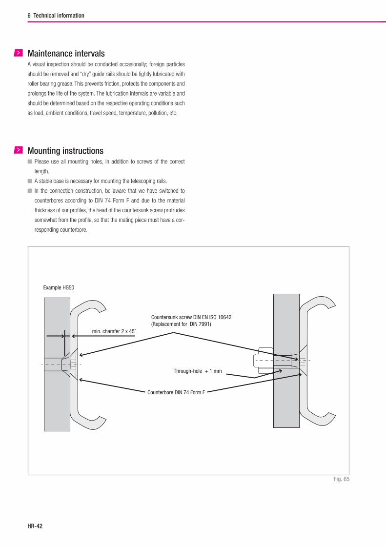
Hegra Rail
HR-42
6 Technical information
Fig. 65
Mounting instructions� Please use all mounting holes, in addition to screws of the correct
length.
� A stable base is necessary for mounting the telescoping rails.
� In the connection construction, be aware that we have switched to
counterbores according to DIN 74 Form F and due to the material
thickness of our profiles, the head of the countersunk screw protrudes
somewhat from the profile, so that the mating piece must have a cor-
responding counterbore.
Example HG50
min. chamfer 2 x 45˚
Through-hole + 1 mm
Counterbore DIN 74 Form F
Countersunk screw DIN EN ISO 10642(Replacement for DIN 7991)
Maintenance intervalsA visual inspection should be conducted occasionally; foreign particles
should be removed and “dry” guide rails should be lightly lubricated with
roller bearing grease. This prevents friction, protects the components and
prolongs the life of the system. The lubrication intervals are variable and
should be determined based on the respective operating conditions such
as load, ambient conditions, travel speed, temperature, pollution, etc.
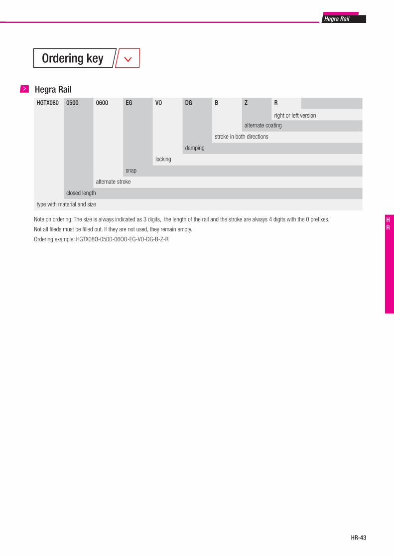
HR-43
Hegra Rail
HR
HGTX080 0500 0600 EG VO DG B Z R
right or left version
alternate coating
stroke in both directions
damping
locking
snap
alternate stroke
closed length
type with material and size
Hegra Rail
Note on ordering: The size is always indicated as 3 digits, the length of the rail and the stroke are always 4 digits with the 0 prefixes.
Not all fileds must be filled out. If they are not used, they remain empty.
Ordering example: HGTX08O-0500-06OO-EG-VO-DG-B-Z-R
Ordering key
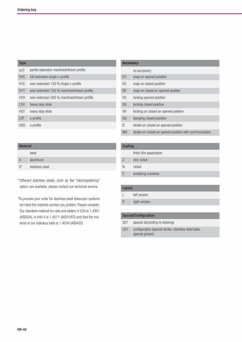
Hegra Rail
HR-44
Type
HTT partial extension machined/drawn profile
HVC full extension single c-profile
H1C over extension 150 % single c-profile
H1T over extension 150 % machined/drawn profile
H2H over extension 200 % machined/drawn profile
LTH heavy duty slide
HGT heavy duty slide
LTF s-profile
HGS s-profile
Accessory
no accessory
EO snap on opened position
EG snap on closed position
EB snap on closed an opened position
VO locking opened position
VG locking closed position
VB locking on closed an opened position
DG damping closed position
B stroke on closed an opened position
BM stroke on closed an opened position with synchronization
Material
steel
A aluminum
X* stainless steel
Coating
thick-film passivation
Z zinc nickel
N nickel
E anodizing colorless
Layout
L left version
R right version
Special/Configuration
S01 special (according to drawing)
C01 configuration (special stroke, stainless steel balls, special grease)
* Different stainless steels, such as the “electropolishing”
option, are available, please contact our technical service.
*To process your order for stainless steel telescopic systems
we need the material number you prefere. Please consider:
Our standard material for rails and sliders in V2A is 1.4301
(AISI304), in V4A it is 1.4571 (AISI316Ti) and that the ma-
terial of our stainless balls is 1.4034 (AISI420)
Ordering key
Telerace
www.rollon.com
Guida Prodotti
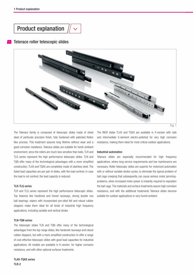
TLR-2
Telerace roller telescopic slides
The Telerace family is composed of telescopic slides made of sheet
steel of particular precision finish, fully hardened with patented Rollon
Nox process. This treatment assures long lifetime without wear and a
good corrosion resistance. Telerace slides are suitable for harsh ambient
environment, since the rollers are much less sensitive than balls. TLR and
TLQ series represent the high performance telescopic slides. TLN and
TQN offer many of the technological advantages with a more simplified
construction, TLAX and TQAX are completely made of stainless steel. The
listed load capacities are per pair of slides, with the load centred. In case
the load is not centred, the load capacity is reduced.
TLR-TLQ series
TLR and TLQ series represent the high performance telescopic slides.
Top features like hardened and honed raceways, strong double row
ball bearings, wipers with incorporated pre-oiled felt and robust rubber
stoppers make them ideal for all kinds of industrial high frequency
applications, including variable and vertical stroke.
TLN-TQN series
The telescopic slides TLN and TQN offer many of the technological
advantages from the top-range slides, like hardened raceways and robust
rubber stoppers, but with a more simplified construction to offer a range
of cost-effective telescopic slides with good load capacities for industrial
applications. All models are available in K-version, for higher corrosion
resistance, and with other optional surfaces treatments.
TLAX-TQAX series
Fig. 1
1 Product explanation
The INOX slides TLAX and TQAX are available in X-version with rails
and intermediate S-element electro-polished for very high corrosion
resistance, making them ideal for most critical outdoor applications.
Industrial automation
Telerace slides are especially recommended for high frequency
applications, where long service requirements and low maintenance are
necessary. Roller telescopic slides are superior for motorized automation
with or without variable stroke-cycles, to eliminate the typical problem of
ball cage creeping that subsequently can cause serious motor jamming-
problems, when increased motor power is instantly required to reposition
the ball cage. The materials and surface treatments assure high corrosion
resistance, and with the additional treatments Telerace slides become
suitable for outdoor applications or very humid ambient.
Product explanation
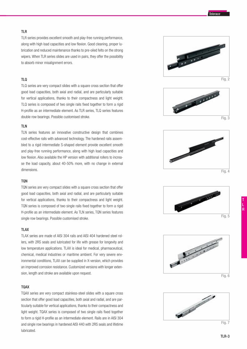
Telerace
TLR-3
TLR
TLN
TLN series features an innovative constructive design that combines
cost-effective rails with advanced technology. The hardened rails assem-
bled to a rigid intermediate S-shaped element provide excellent smooth
and play-free running performance, along with high load capacities and
low flexion. Also available the HP version with additional rollers to increa-
se the load capacity, about 40-50% more, with no change in external
dimensions.
TLAX
TLAX series are made of AISI 304 rails and AISI 404 hardened steel rol-
lers, with 2RS seals and lubricated for life with grease for longevity and
low temperature applications. TLAX is ideal for medical, pharmaceutical,
chemical, medical industries or maritime ambient. For very severe env-
ironmental conditions, TLAX can be supplied in X-version, which provides
an improved corrosion resistance. Customized versions with longer exten-
sion, length and stroke are available upon request.
Fig. 4
Fig. 6
TLR
TLR series provides excellent smooth and play-free running performance,
along with high load capacities and low flexion. Good cleaning, proper lu-
brication and reduced maintenance thanks to pre-oiled felts on the strong
wipers. When TLR series slides are used in pairs, they offer the possibility
to absorb minor misalignment errors.
Fig. 2
Fig. 3
Fig. 5
Fig. 7
TQN
TQN series are very compact slides with a square cross section that offer
good load capacities, both axial and radial, and are particularly suitable
for vertical applications, thanks to their compactness and light weight.
TQN series is composed of two single rails fixed together to form a rigid
H-profile as an intermediate element. As TLN series, TQN series features
single row bearings. Possible customised stroke.
TQAX
TQAX series are very compact stainless-steel slides with a square cross
section that offer good load capacities, both axial and radial, and are par-
ticularly suitable for vertical applications, thanks to their compactness and
light weight. TQAX series is composed of two single rails fixed together
to form a rigid H-profile as an intermediate element. Rails are in AISI 304
and single row bearings in hardened AISI 440 with 2RS seals and lifetime
lubricated.
TLQ
TLQ series are very compact slides with a square cross section that offer
good load capacities, both axial and radial, and are particularly suitable
for vertical applications, thanks to their compactness and light weight.
TLQ series is composed of two single rails fixed together to form a rigid
H-profile as an intermediate element. As TLR series, TLQ series features
double row bearings. Possible customised stroke.
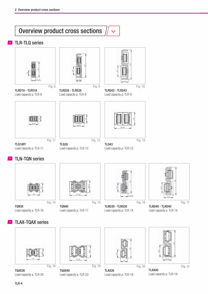
TLR-4
Fig. 8
Fig. 14
Fig. 18
TLR-TLQ series
Fig. 10
Fig. 16
Fig. 20
Fig. 11
Fig. 17
Fig. 21
Fig. 9
Fig. 15
Fig. 19
TLN-TQN series
TLAX-TQAX series
TLRD43 - TLRS43Load capacity p. TLR-9
TLRD28 - TLRS28Load capacity p. TLR-9
TLRD18 - TLRS18Load capacity p. TLR-8
TLQ43Load capacity p. TLR-12
Fig. 12 Fig. 13TLQ28Load capacity p. TLR-12
TLQ18FFLoad capacity p. TLR-11
TLND40 - TLNS40Load capacity p. TLR-14
TLND30 - TLNS30Load capacity p. TLR-14
TQN40Load capacity p. TLR-17
TQN30Load capacity p. TLR-16
TLAX40Load capacity p. TLR-19
TLAX26Load capacity p. TLR-19
TQAX26Load capacity p. TLR-20
TQAX40Load capacity p. TLR-20
Overview product cross sections
2 Overview product cross sections
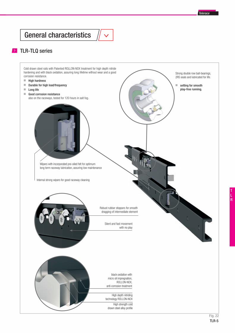
Telerace
TLR-5
TLR
Internal strong wipers for good raceway cleaning
Wipers with incorporated pre-oiled felt for optimum long term raceway lubrication, assuring low maintenance
Cold drawn steel rails with Patented ROLLON-NOX treatment for high depth nitride hardening and with black oxidation, assuring long lifetime without wear and a good corrosion resistance.■ High hardness■ Durable for high load/frequency■ Long life■ Good corrosion resistance also on the raceways, tested for 120 hours in salt fog.
Strong double row ball-bearings, 2RS seals and lubricated for life.
■ setting for smooth play-free running.
black oxidation with micro oil impregnation,
ROLLON-NOX, anti-corrosion treatment
High strength cold drawn steel alloy profi le
High depth nitriding technology ROLLON-NOX
Silent and fast movement with no play
Robust rubber stoppers for smooth dragging of intermediate element
TLR-TLQ series
Fig. 22
General characteristics
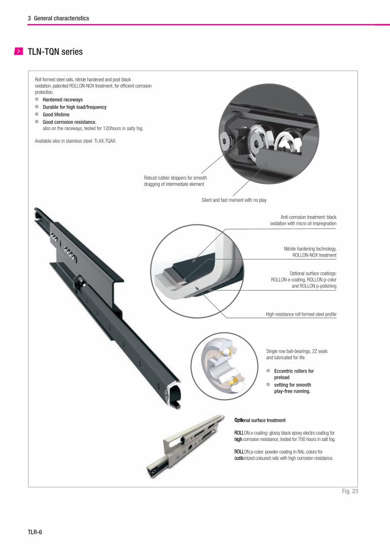
TLR-6
TLN-TQN series
Roll formed steel rails, nitride hardened and post black oxidation, patented ROLLON-NOX treatment, for effi cient corrosion protection.■ Hardened raceways ■ Durable for high load/frequency■ Good lifetime■ Good corrosion resistance, also on the raceways, tested for 120hours in salty fog.
Available also in stainless steel: TLAX,TQAX.
Optional surface treatment
ROLLON e-coating: glossy black epoxy electro coating for high corrosion resistance, tested for 700 hours in salt fog.
ROLLON p-color: powder coating in RAL-colors for customized coloured rails with high corrosion resistance.
Optional surface treatment
ROLLON high corrosion resistance, tested for 700 hours in salt fog.
ROLLON p-color: powder coating in RAL-colors for customized coloured rails with high corrosion resistance.
Single row ball-bearings, 2Z seals and lubricated for life.
■ Eccentric rollers for preload ■ setting for smooth play-free running.
Robust rubber stoppers for smooth dragging of intermediate element
Silent and fast moment with no play
High resistance roll formed steel profi le
Anti-corrosion treatment: black oxidation with micro oil impregnation
Nitride hardening technology, ROLLON-NOX treatment
Optional surface coatings:ROLLON e-coating, ROLLON p-color
and ROLLON p-polishing
Fig. 23
3 General characteristics
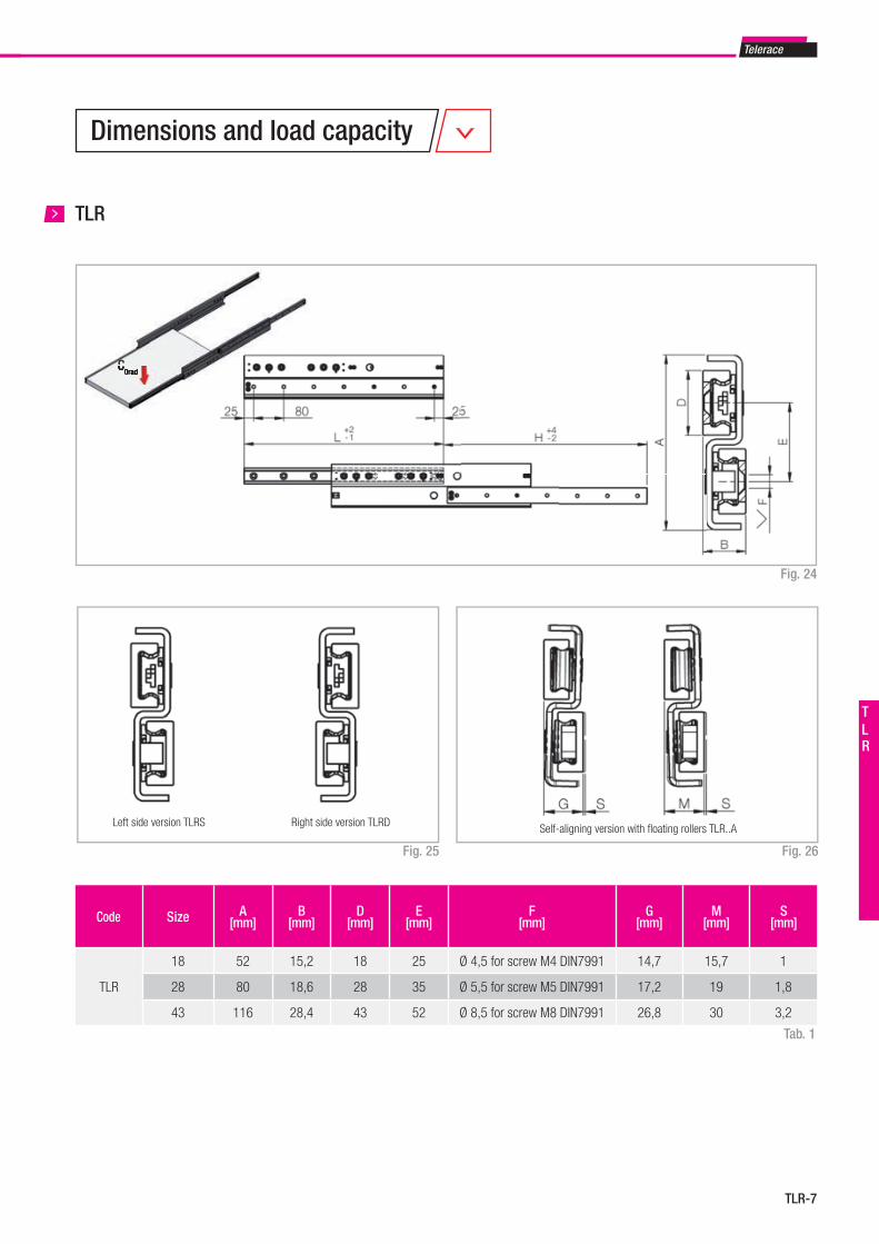
Telerace
TLR-7
TLR
TLR
Fig. 24
Right side version TLRDLeft side version TLRS Self-aligning version with fl oating rollers TLR..A
Code Size A[mm]
B[mm]
D[mm]
E[mm]
F[mm]
G[mm]
M[mm]
S[mm]
TLR
18 52 15,2 18 25 Ø 4,5 for screw M4 DIN7991 14,7 15,7 1
28 80 18,6 28 35 Ø 5,5 for screw M5 DIN7991 17,2 19 1,8
43 116 28,4 43 52 Ø 8,5 for screw M8 DIN7991 26,8 30 3,2
Fig. 26Fig. 25
Tab. 1
C0radC0rad
Dimensions and load capacity
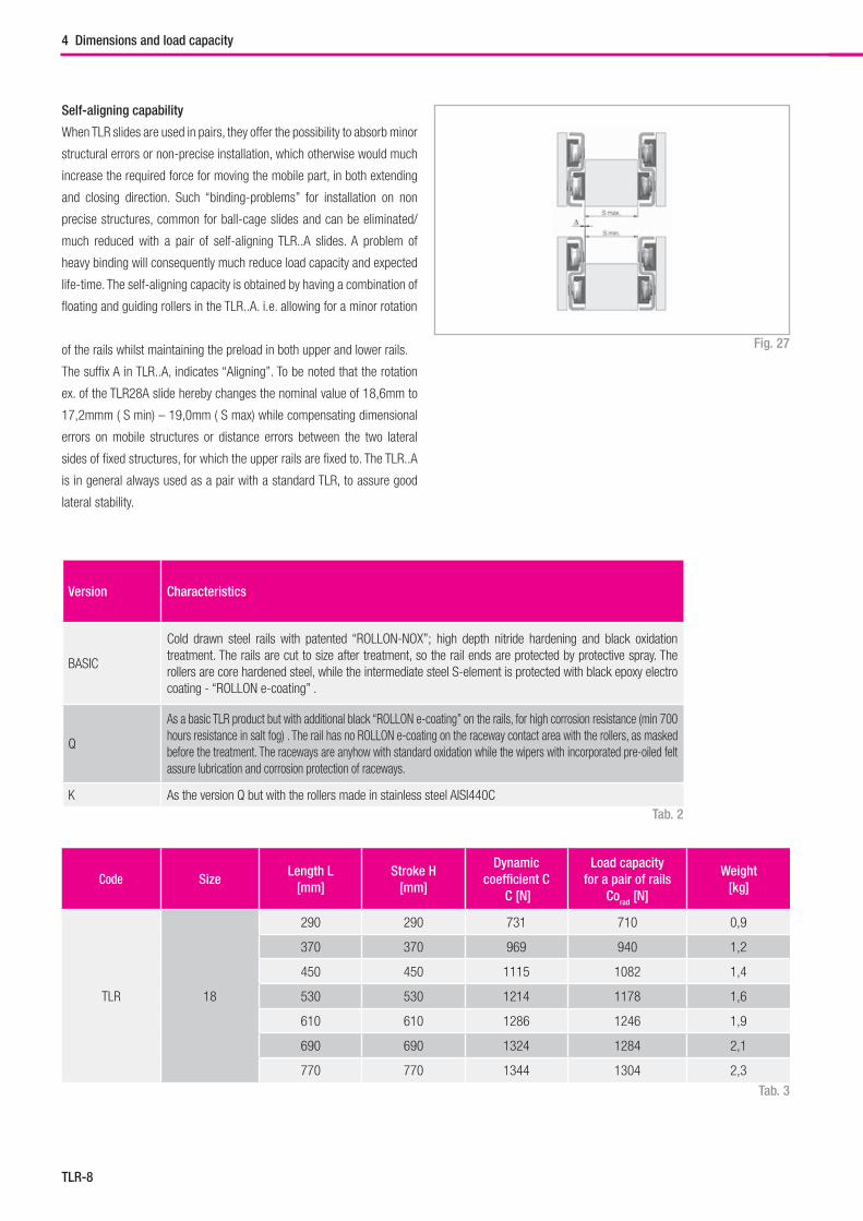
TLR-8
Self-aligning capability
When TLR slides are used in pairs, they offer the possibility to absorb minor
structural errors or non-precise installation, which otherwise would much
increase the required force for moving the mobile part, in both extending
and closing direction. Such “binding-problems” for installation on non
precise structures, common for ball-cage slides and can be eliminated/
much reduced with a pair of self-aligning TLR..A slides. A problem of
heavy binding will consequently much reduce load capacity and expected
life-time. The self-aligning capacity is obtained by having a combination of
floating and guiding rollers in the TLR..A. i.e. allowing for a minor rotation
of the rails whilst maintaining the preload in both upper and lower rails.
The suffix A in TLR..A, indicates “Aligning”. To be noted that the rotation
ex. of the TLR28A slide hereby changes the nominal value of 18,6mm to
17,2mmm ( S min) – 19,0mm ( S max) while compensating dimensional
errors on mobile structures or distance errors between the two lateral
sides of fixed structures, for which the upper rails are fixed to. The TLR..A
is in general always used as a pair with a standard TLR, to assure good
lateral stability.
Fig. 27
Version Characteristics
BASIC
Cold drawn steel rails with patented “ROLLON-NOX”; high depth nitride hardening and black oxidation treatment. The rails are cut to size after treatment, so the rail ends are protected by protective spray. The rollers are core hardened steel, while the intermediate steel S-element is protected with black epoxy electro coating - “ROLLON e-coating” .
Q
As a basic TLR product but with additional black “ROLLON e-coating” on the rails, for high corrosion resistance (min 700 hours resistance in salt fog) . The rail has no ROLLON e-coating on the raceway contact area with the rollers, as masked before the treatment. The raceways are anyhow with standard oxidation while the wipers with incorporated pre-oiled felt assure lubrication and corrosion protection of raceways.
K As the version Q but with the rollers made in stainless steel AISI440C
Code SizeLength L
[mm]Stroke H
[mm]
Dynamic coefficient C
C [N]
Load capacity for a pair of rails
Corad [N]
Weight[kg]
TLR 18
290 290 731 710 0,9
370 370 969 940 1,2
450 450 1115 1082 1,4
530 530 1214 1178 1,6
610 610 1286 1246 1,9
690 690 1324 1284 2,1
770 770 1344 1304 2,3
Tab. 2
Tab. 3
4 Dimensions and load capacity
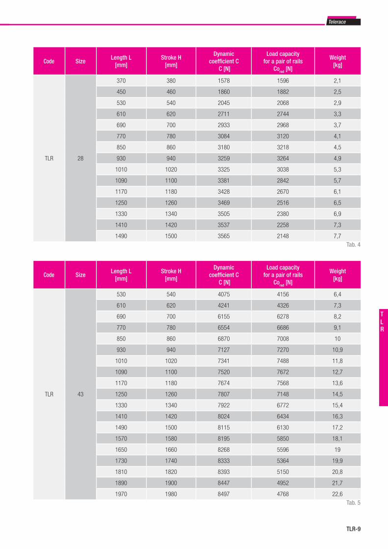
Telerace
TLR-9
TLR
Code SizeLength L
[mm]Stroke H
[mm]
Dynamic coefficient C
C [N]
Load capacity for a pair of rails
Corad [N]
Weight[kg]
TLR 28
370 380 1578 1596 2,1
450 460 1860 1882 2,5
530 540 2045 2068 2,9
610 620 2711 2744 3,3
690 700 2933 2968 3,7
770 780 3084 3120 4,1
850 860 3180 3218 4,5
930 940 3259 3264 4,9
1010 1020 3325 3038 5,3
1090 1100 3381 2842 5,7
1170 1180 3428 2670 6,1
1250 1260 3469 2516 6,5
1330 1340 3505 2380 6,9
1410 1420 3537 2258 7,3
1490 1500 3565 2148 7,7
Code SizeLength L
[mm]Stroke H
[mm]
Dynamic coefficient C
C [N]
Load capacity for a pair of rails
Corad [N]
Weight[kg]
TLR 43
530 540 4075 4156 6,4
610 620 4241 4326 7,3
690 700 6155 6278 8,2
770 780 6554 6686 9,1
850 860 6870 7008 10
930 940 7127 7270 10,9
1010 1020 7341 7488 11,8
1090 1100 7520 7672 12,7
1170 1180 7674 7568 13,6
1250 1260 7807 7148 14,5
1330 1340 7922 6772 15,4
1410 1420 8024 6434 16,3
1490 1500 8115 6130 17,2
1570 1580 8195 5850 18,1
1650 1660 8268 5596 19
1730 1740 8333 5364 19,9
1810 1820 8393 5150 20,8
1890 1900 8447 4952 21,7
1970 1980 8497 4768 22,6
Tab. 4
Tab. 5
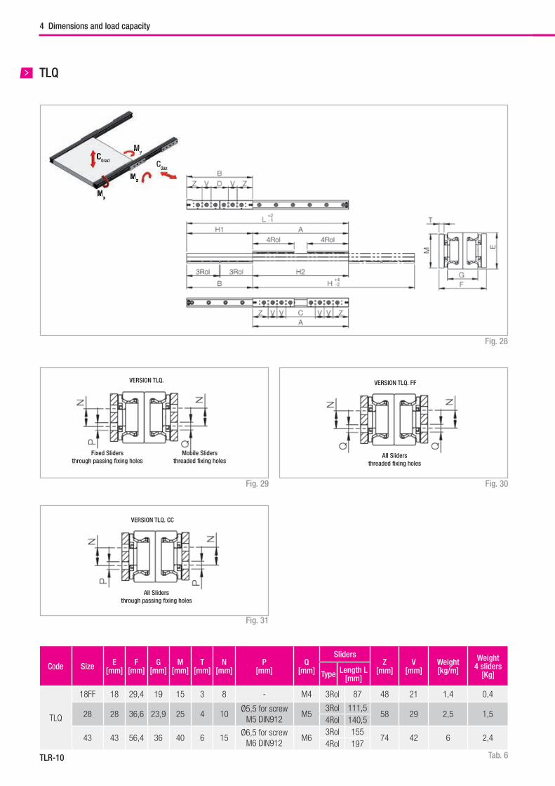
TLR-10
TLQ
Fig. 28
VERSION TLQ.
Fixed Slidersthrough passing fi xing holes
Mobile Slidersthreaded fi xing holes
VERSION TLQ. FF
All Slidersthreaded fi xing holes
VERSION TLQ. CC
All Slidersthrough passing fi xing holes
Code Size E[mm]
F [mm]
G [mm]
M[mm]
T[mm]
N[mm]
P[mm]
Q[mm]
SlidersZ
[mm]V
[mm]Weight[kg/m]
Weight4 sliders
[Kg]Type Length L[mm]
TLQ
18FF 18 29,4 19 15 3 8 - M4 3Rol 87 48 21 1,4 0,4
28 28 36,6 23,9 25 4 10Ø5,5 for screw
M5 DIN912M5
3Rol 111,558 29 2,5 1,5
4Rol 140,5
43 43 56,4 36 40 6 15Ø6,5 for screw
M6 DIN912M6
3Rol 15574 42 6 2,4
4Rol 197
Fig. 29 Fig. 30
Fig. 31
Tab. 6
4 Dimensions and load capacity
C0ax
Mz
My
Mx
0ax
Mz
Mx
MyC0radC
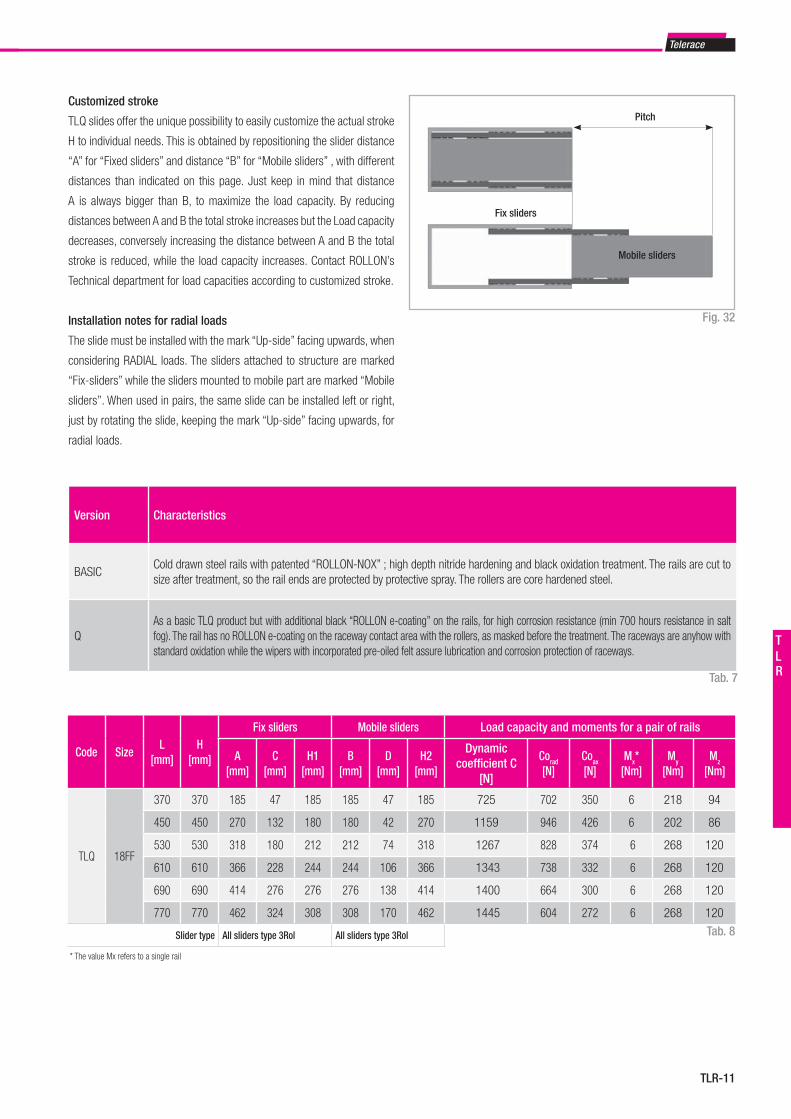
Telerace
TLR-11
TLR
Customized stroke
TLQ slides offer the unique possibility to easily customize the actual stroke
H to individual needs. This is obtained by repositioning the slider distance
“A” for “Fixed sliders” and distance “B” for “Mobile sliders” , with different
distances than indicated on this page. Just keep in mind that distance
A is always bigger than B, to maximize the load capacity. By reducing
distances between A and B the total stroke increases but the Load capacity
decreases, conversely increasing the distance between A and B the total
stroke is reduced, while the load capacity increases. Contact ROLLON’s
Technical department for load capacities according to customized stroke.
Installation notes for radial loads
The slide must be installed with the mark “Up-side” facing upwards, when
considering RADIAL loads. The sliders attached to structure are marked
“Fix-sliders” while the sliders mounted to mobile part are marked “Mobile
sliders”. When used in pairs, the same slide can be installed left or right,
just by rotating the slide, keeping the mark “Up-side” facing upwards, for
radial loads.
Version Characteristics
BASICCold drawn steel rails with patented “ROLLON-NOX” ; high depth nitride hardening and black oxidation treatment. The rails are cut to size after treatment, so the rail ends are protected by protective spray. The rollers are core hardened steel.
QAs a basic TLQ product but with additional black “ROLLON e-coating” on the rails, for high corrosion resistance (min 700 hours resistance in salt fog). The rail has no ROLLON e-coating on the raceway contact area with the rollers, as masked before the treatment. The raceways are anyhow with standard oxidation while the wipers with incorporated pre-oiled felt assure lubrication and corrosion protection of raceways.
Code SizeL
[mm]H
[mm]
Fix sliders Mobile sliders Load capacity and moments for a pair of rails
A[mm]
C[mm]
H1[mm]
B[mm]
D[mm]
H2[mm]
Dynamic coefficient C
[N]
Corad
[N]Coax
[N]Mx*
[Nm]My
[Nm]Mz
[Nm]
TLQ 18FF
370 370 185 47 185 185 47 185 725 702 350 6 218 94
450 450 270 132 180 180 42 270 1159 946 426 6 202 86
530 530 318 180 212 212 74 318 1267 828 374 6 268 120
610 610 366 228 244 244 106 366 1343 738 332 6 268 120
690 690 414 276 276 276 138 414 1400 664 300 6 268 120
770 770 462 324 308 308 170 462 1445 604 272 6 268 120
Slider type All sliders type 3Rol All sliders type 3Rol
Mobile sliders
Pitch
Fix sliders
Fig. 32
Tab. 7
Tab. 8
* The value Mx refers to a single rail
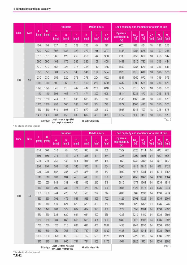
TLR-12
Code SizeL
[mm]H
[mm]
Fix sliders Mobile sliders Load capacity and moments for a pair of rails
A[mm]
C[mm]
H1[mm]
B[mm]
D[mm]
H2[mm]
Dynamic coefficient C
[N]
Corad
[N]Coax
[N]Mx*
[Nm]My
[Nm]Mz
[Nm]
TLQ 43
610 600 310 78 300 310 78 300 1529 2228 1114 64 648 864
690 690 374 142 316 316 84 374 2326 3390 1694 64 680 906
770 770 456 140 314 314 82 456 3052 4448 2068 64 668 892
850 850 504 188 346 346 114 504 3305 4816 1916 64 842 1122
930 930 552 236 378 378 146 552 3509 4978 1784 64 1014 1352
1010 1010 600 284 410 410 178 600 3676 4656 1668 64 1036 1584
1090 1090 648 332 442 442 210 648 3816 4374 1568 64 1036 1814
1170 1170 696 380 474 474 242 696 3935 4126 1478 64 1036 2044
1250 1250 744 428 506 506 274 744 4037 3902 1398 64 1036 2274
1330 1330 792 476 538 538 306 792 4126 3702 1326 64 1036 2504
1410 1410 840 524 570 570 338 840 4204 3522 1262 64 1036 2736
1490 1490 888 572 602 602 370 888 4272 3358 1204 64 1036 2892
1570 1570 936 620 634 634 402 936 4334 3210 1150 64 1036 2892
1650 1650 984 668 666 666 434 984 4389 3072 1102 64 1036 2892
1730 1730 1032 716 698 698 466 1032 4438 2948 1056 64 1036 2892
1810 1810 1080 764 730 730 498 1080 4483 2832 1014 64 1036 2892
1890 1890 1128 812 762 762 530 1128 4524 2726 976 64 1036 2892
1970 1970 1176 860 794 794 562 1176 4561 2626 940 64 1036 2892
Slider typeLength 610 e 690 type 3Rol from Length 770 type 4Rol
All sliders type 3Rol Tab.10
Code SizeL
[mm]H
[mm]
Fix sliders Mobile sliders Load capacity and moments for a pair of rails
A[mm]
C[mm]
H1[mm]
B[mm]
D[mm]
H2[mm]
Dynamic coefficient C
[N]
Corad
[N]Coax
[N]Mx*
[Nm]My
[Nm]Mz
[Nm]
TLQ 28
450 450 227 53 223 223 49 227 602 928 464 18 192 256
530 530 307 133 223 223 49 307 1138 1754 876 18 192 256
610 610 360 128 250 250 76 360 1335 2058 808 18 256 342
690 690 408 176 282 282 108 408 1458 1916 732 18 316 444
770 770 456 224 314 314 140 456 1552 1754 670 18 316 546
850 850 504 272 346 346 172 504 1626 1616 618 18 316 576
930 930 552 320 378 378 204 552 1687 1500 572 18 316 576
1010 1010 600 368 410 410 236 600 1737 1398 534 18 316 576
1090 1090 648 416 442 442 268 648 1779 1310 500 18 316 576
1170 1170 696 464 474 474 300 696 1814 1232 470 18 316 576
1250 1250 744 512 506 506 332 744 1845 1162 444 18 316 576
1330 1330 792 560 538 538 364 792 1872 1100 420 18 316 576
1410 1410 840 608 570 570 396 840 1896 1044 400 18 316 576
1490 1490 888 656 602 602 428 888 1917 994 380 18 316 576
Slider typeLength 450 e 530 type 3Rol from Length 610 type 4Rol
All sliders type 3Rol Tab. 9
* The value Mx refers to a single rail
* The value Mx refers to a single rail
4 Dimensions and load capacity
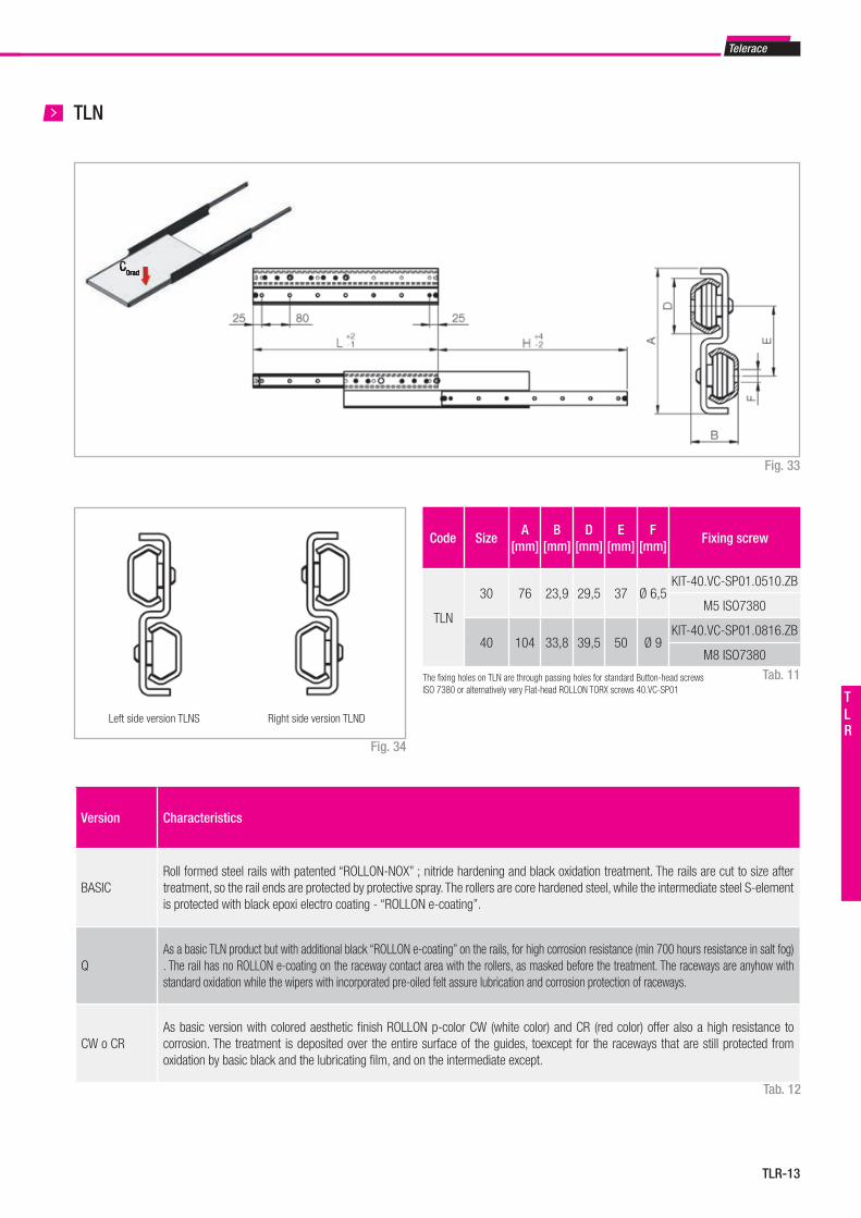
Telerace
TLR-13
TLR
TLN
Fig. 33
Version Characteristics
BASICRoll formed steel rails with patented “ROLLON-NOX” ; nitride hardening and black oxidation treatment. The rails are cut to size after treatment, so the rail ends are protected by protective spray. The rollers are core hardened steel, while the intermediate steel S-element is protected with black epoxi electro coating - “ROLLON e-coating”.
QAs a basic TLN product but with additional black “ROLLON e-coating” on the rails, for high corrosion resistance (min 700 hours resistance in salt fog) . The rail has no ROLLON e-coating on the raceway contact area with the rollers, as masked before the treatment. The raceways are anyhow with standard oxidation while the wipers with incorporated pre-oiled felt assure lubrication and corrosion protection of raceways.
CW o CRAs basic version with colored aesthetic fi nish ROLLON p-color CW (white color) and CR (red color) offer also a high resistance to corrosion. The treatment is deposited over the entire surface of the guides, toexcept for the raceways that are still protected from oxidation by basic black and the lubricating fi lm, and on the intermediate except.
Tab. 12
Right side version TLNDLeft side version TLNS
Code SizeA
[mm]B
[mm]D
[mm]E
[mm]F
[mm]Fixing screw
TLN
30 76 23,9 29,5 37 Ø 6,5KIT-40.VC-SP01.0510.ZB
M5 ISO7380
40 104 33,8 39,5 50 Ø 9KIT-40.VC-SP01.0816.ZB
M8 ISO7380
The fi xing holes on TLN are through passing holes for standard Button-head screwsISO 7380 or alternatively very Flat-head ROLLON TORX screws 40.VC-SP01
Fig. 34
Tab. 11
C0radC0rad
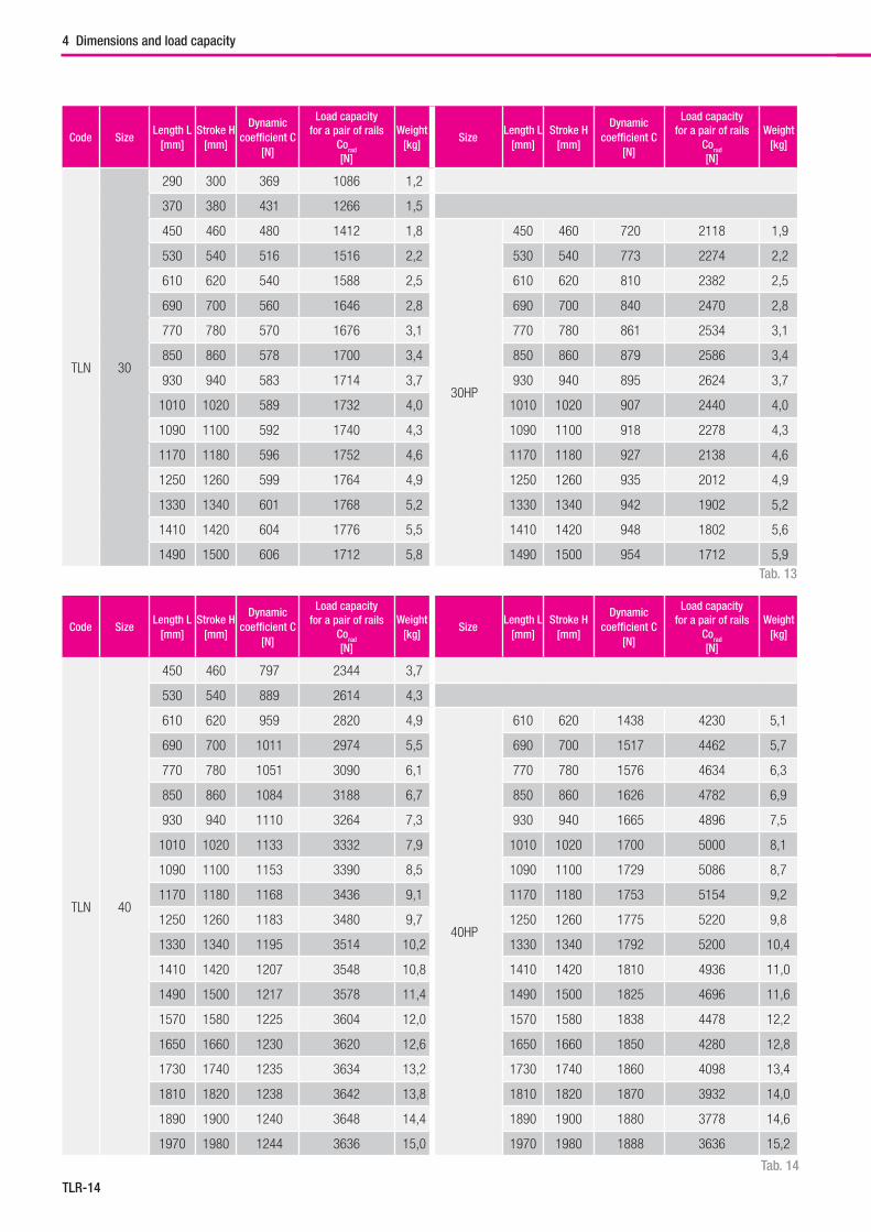
TLR-14
Code SizeLength L
[mm]Stroke H
[mm]
Dynamic coefficient C
[N]
Load capacity for a pair of rails
Corad [N]
Weight[kg]
SizeLength L
[mm]Stroke H
[mm]
Dynamic coefficient C
[N]
Load capacity for a pair of rails
Corad [N]
Weight[kg]
TLN 30
290 300 369 1086 1,2
370 380 431 1266 1,5
450 460 480 1412 1,8
30HP
450 460 720 2118 1,9
530 540 516 1516 2,2 530 540 773 2274 2,2
610 620 540 1588 2,5 610 620 810 2382 2,5
690 700 560 1646 2,8 690 700 840 2470 2,8
770 780 570 1676 3,1 770 780 861 2534 3,1
850 860 578 1700 3,4 850 860 879 2586 3,4
930 940 583 1714 3,7 930 940 895 2624 3,7
1010 1020 589 1732 4,0 1010 1020 907 2440 4,0
1090 1100 592 1740 4,3 1090 1100 918 2278 4,3
1170 1180 596 1752 4,6 1170 1180 927 2138 4,6
1250 1260 599 1764 4,9 1250 1260 935 2012 4,9
1330 1340 601 1768 5,2 1330 1340 942 1902 5,2
1410 1420 604 1776 5,5 1410 1420 948 1802 5,6
1490 1500 606 1712 5,8 1490 1500 954 1712 5,9
Code SizeLength L
[mm]Stroke H
[mm]
Dynamic coefficient C
[N]
Load capacity for a pair of rails
Corad [N]
Weight[kg]
SizeLength L
[mm]Stroke H
[mm]
Dynamic coefficient C
[N]
Load capacity for a pair of rails
Corad [N]
Weight[kg]
TLN 40
450 460 797 2344 3,7
530 540 889 2614 4,3
610 620 959 2820 4,9
40HP
610 620 1438 4230 5,1
690 700 1011 2974 5,5 690 700 1517 4462 5,7
770 780 1051 3090 6,1 770 780 1576 4634 6,3
850 860 1084 3188 6,7 850 860 1626 4782 6,9
930 940 1110 3264 7,3 930 940 1665 4896 7,5
1010 1020 1133 3332 7,9 1010 1020 1700 5000 8,1
1090 1100 1153 3390 8,5 1090 1100 1729 5086 8,7
1170 1180 1168 3436 9,1 1170 1180 1753 5154 9,2
1250 1260 1183 3480 9,7 1250 1260 1775 5220 9,8
1330 1340 1195 3514 10,2 1330 1340 1792 5200 10,4
1410 1420 1207 3548 10,8 1410 1420 1810 4936 11,0
1490 1500 1217 3578 11,4 1490 1500 1825 4696 11,6
1570 1580 1225 3604 12,0 1570 1580 1838 4478 12,2
1650 1660 1230 3620 12,6 1650 1660 1850 4280 12,8
1730 1740 1235 3634 13,2 1730 1740 1860 4098 13,4
1810 1820 1238 3642 13,8 1810 1820 1870 3932 14,0
1890 1900 1240 3648 14,4 1890 1900 1880 3778 14,6
1970 1980 1244 3636 15,0 1970 1980 1888 3636 15,2
Tab. 13
Tab. 14
4 Dimensions and load capacity
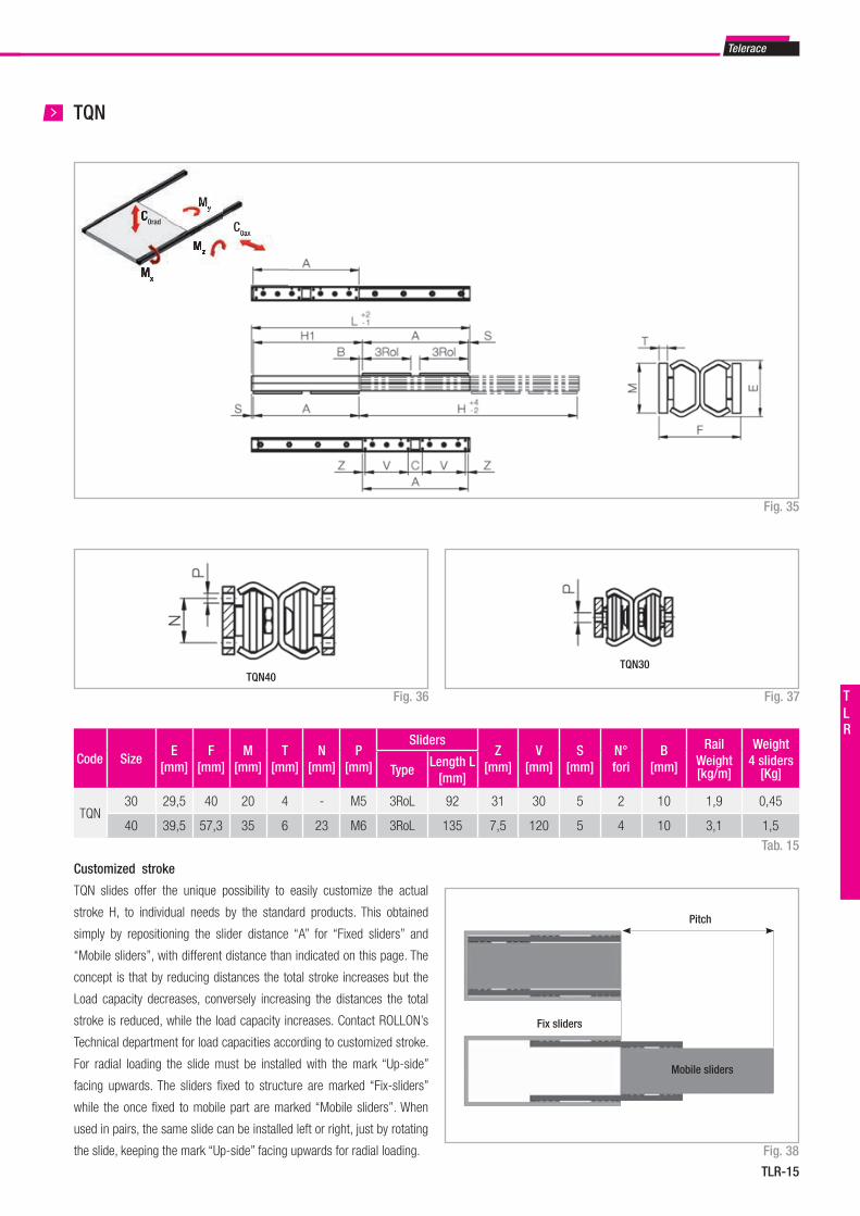
Telerace
TLR-15
TLR
TQN
Fig. 35
TQN40TQN30
Code SizeE
[mm]F
[mm]M
[mm]T
[mm]N
[mm]P
[mm]
SlidersZ
[mm]V
[mm]S
[mm]N° fori
B[mm]
Rail Weight[kg/m]
Weight4 sliders
[Kg]TypeLength L
[mm]
TQN30 29,5 40 20 4 - M5 3RoL 92 31 30 5 2 10 1,9 0,45
40 39,5 57,3 35 6 23 M6 3RoL 135 7,5 120 5 4 10 3,1 1,5
Tab. 15
Fig. 37Fig. 36
Fig. 38
Mobile sliders
Pitch
Fix sliders
Customized stroke
TQN slides offer the unique possibility to easily customize the actual
stroke H, to individual needs by the standard products. This obtained
simply by repositioning the slider distance “A” for “Fixed sliders” and
“Mobile sliders”, with different distance than indicated on this page. The
concept is that by reducing distances the total stroke increases but the
Load capacity decreases, conversely increasing the distances the total
stroke is reduced, while the load capacity increases. Contact ROLLON’s
Technical department for load capacities according to customized stroke.
For radial loading the slide must be installed with the mark “Up-side”
facing upwards. The sliders fi xed to structure are marked “Fix-sliders”
while the once fi xed to mobile part are marked “Mobile sliders”. When
used in pairs, the same slide can be installed left or right, just by rotating
the slide, keeping the mark “Up-side” facing upwards for radial loading.
C0ax
Mz
My
Mx
0ax
MMz
MMx
MyC0radC
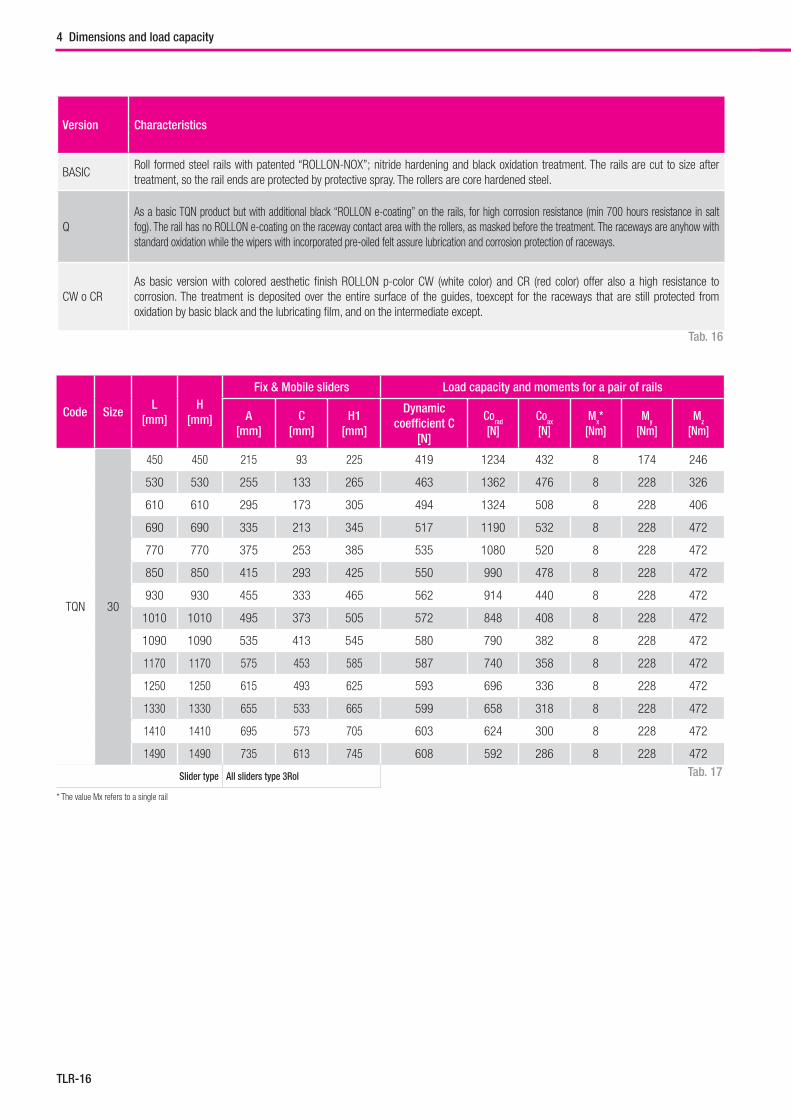
TLR-16
Version Characteristics
BASICRoll formed steel rails with patented “ROLLON-NOX”; nitride hardening and black oxidation treatment. The rails are cut to size after treatment, so the rail ends are protected by protective spray. The rollers are core hardened steel.
QAs a basic TQN product but with additional black “ROLLON e-coating” on the rails, for high corrosion resistance (min 700 hours resistance in salt fog). The rail has no ROLLON e-coating on the raceway contact area with the rollers, as masked before the treatment. The raceways are anyhow with standard oxidation while the wipers with incorporated pre-oiled felt assure lubrication and corrosion protection of raceways.
CW o CRAs basic version with colored aesthetic finish ROLLON p-color CW (white color) and CR (red color) offer also a high resistance to corrosion. The treatment is deposited over the entire surface of the guides, toexcept for the raceways that are still protected from oxidation by basic black and the lubricating film, and on the intermediate except.
Code SizeL
[mm]H
[mm]
Fix & Mobile sliders Load capacity and moments for a pair of rails
A[mm]
C[mm]
H1[mm]
Dynamic coefficient C
[N]
Corad
[N]Coax
[N]Mx*
[Nm]My
[Nm]Mz
[Nm]
TQN 30
450 450 215 93 225 419 1234 432 8 174 246
530 530 255 133 265 463 1362 476 8 228 326
610 610 295 173 305 494 1324 508 8 228 406
690 690 335 213 345 517 1190 532 8 228 472
770 770 375 253 385 535 1080 520 8 228 472
850 850 415 293 425 550 990 478 8 228 472
930 930 455 333 465 562 914 440 8 228 472
1010 1010 495 373 505 572 848 408 8 228 472
1090 1090 535 413 545 580 790 382 8 228 472
1170 1170 575 453 585 587 740 358 8 228 472
1250 1250 615 493 625 593 696 336 8 228 472
1330 1330 655 533 665 599 658 318 8 228 472
1410 1410 695 573 705 603 624 300 8 228 472
1490 1490 735 613 745 608 592 286 8 228 472
Slider type All sliders type 3Rol
Tab. 16
* The value Mx refers to a single rail
Tab. 17
4 Dimensions and load capacity
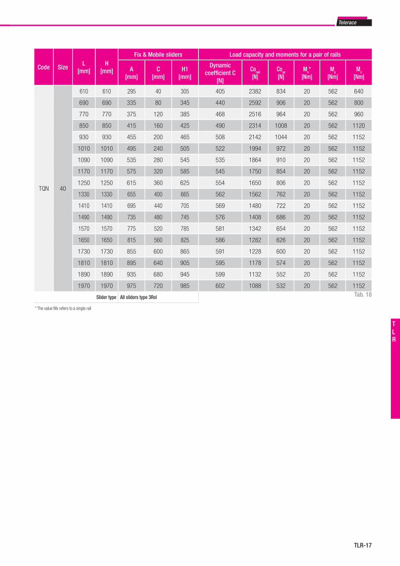
Telerace
TLR-17
TLR
Code SizeL
[mm]H
[mm]
Fix & Mobile sliders Load capacity and moments for a pair of rails
A[mm]
C[mm]
H1[mm]
Dynamic coefficient C
[N]
Corad
[N]Coax
[N]Mx*
[Nm]My
[Nm]Mz
[Nm]
TQN 40
610 610 295 40 305 405 2382 834 20 562 640
690 690 335 80 345 440 2592 906 20 562 800
770 770 375 120 385 468 2516 964 20 562 960
850 850 415 160 425 490 2314 1008 20 562 1120
930 930 455 200 465 508 2142 1044 20 562 1152
1010 1010 495 240 505 522 1994 972 20 562 1152
1090 1090 535 280 545 535 1864 910 20 562 1152
1170 1170 575 320 585 545 1750 854 20 562 1152
1250 1250 615 360 625 554 1650 806 20 562 1152
1330 1330 655 400 665 562 1562 762 20 562 1152
1410 1410 695 440 705 569 1480 722 20 562 1152
1490 1490 735 480 745 576 1408 686 20 562 1152
1570 1570 775 520 785 581 1342 654 20 562 1152
1650 1650 815 560 825 586 1282 626 20 562 1152
1730 1730 855 600 865 591 1228 600 20 562 1152
1810 1810 895 640 905 595 1178 574 20 562 1152
1890 1890 935 680 945 599 1132 552 20 562 1152
1970 1970 975 720 985 602 1088 532 20 562 1152
Slider type All sliders type 3Rol Tab. 18
* The value Mx refers to a single rail
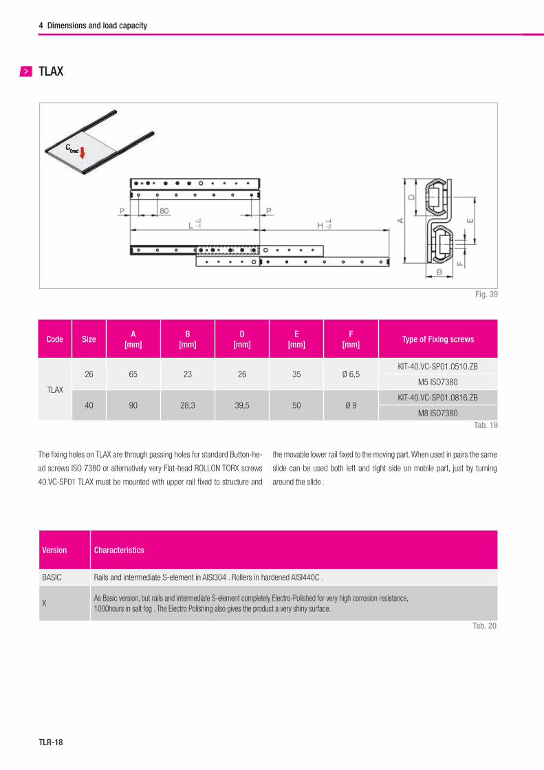
TLR-18
TLAX
Code SizeA
[mm]B
[mm]D
[mm]E
[mm]F
[mm]Type of Fixing screws
TLAX
26 65 23 26 35 Ø 6,5KIT-40.VC-SP01.0510.ZB
M5 ISO7380
40 90 28,3 39,5 50 Ø 9KIT-40.VC-SP01.0816.ZB
M8 ISO7380
The fi xing holes on TLAX are through passing holes for standard Button-he-
ad screws ISO 7380 or alternatively very Flat-head ROLLON TORX screws
40.VC-SP01 TLAX must be mounted with upper rail fi xed to structure and
Version Characteristics
BASIC Rails and intermediate S-element in AISI304 . Rollers in hardened AISI440C .
XAs Basic version, but rails and intermediate S-element completely Electro-Polished for very high corrosion resistance,1000hours in salt fog . The Electro Polishing also gives the product a very shiny surface.
the movable lower rail fi xed to the moving part. When used in pairs the same
slide can be used both left and right side on mobile part, just by turning
around the slide .
Fig. 39
Tab. 19
Tab. 20
4 Dimensions and load capacity
C0radC0rad
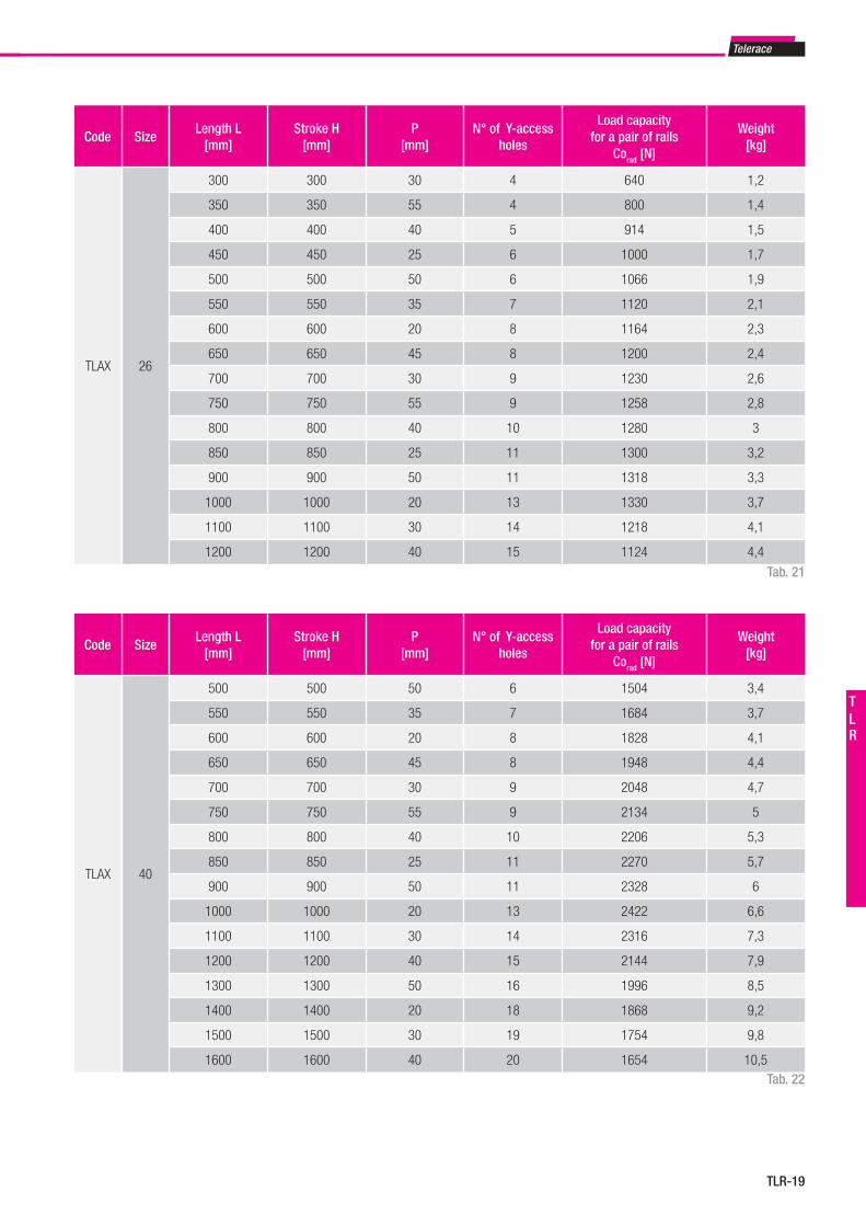
Telerace
TLR-19
TLR
Code SizeLength L
[mm]Stroke H
[mm]P
[mm]N° of Y-access
holes
Load capacity for a pair of rails
Corad [N]
Weight[kg]
TLAX 26
300 300 30 4 640 1,2
350 350 55 4 800 1,4
400 400 40 5 914 1,5
450 450 25 6 1000 1,7
500 500 50 6 1066 1,9
550 550 35 7 1120 2,1
600 600 20 8 1164 2,3
650 650 45 8 1200 2,4
700 700 30 9 1230 2,6
750 750 55 9 1258 2,8
800 800 40 10 1280 3
850 850 25 11 1300 3,2
900 900 50 11 1318 3,3
1000 1000 20 13 1330 3,7
1100 1100 30 14 1218 4,1
1200 1200 40 15 1124 4,4
Code SizeLength L
[mm]Stroke H
[mm]P
[mm]N° of Y-access
holes
Load capacity for a pair of rails
Corad [N]
Weight[kg]
TLAX 40
500 500 50 6 1504 3,4
550 550 35 7 1684 3,7
600 600 20 8 1828 4,1
650 650 45 8 1948 4,4
700 700 30 9 2048 4,7
750 750 55 9 2134 5
800 800 40 10 2206 5,3
850 850 25 11 2270 5,7
900 900 50 11 2328 6
1000 1000 20 13 2422 6,6
1100 1100 30 14 2316 7,3
1200 1200 40 15 2144 7,9
1300 1300 50 16 1996 8,5
1400 1400 20 18 1868 9,2
1500 1500 30 19 1754 9,8
1600 1600 40 20 1654 10,5
Tab. 21
Tab. 22
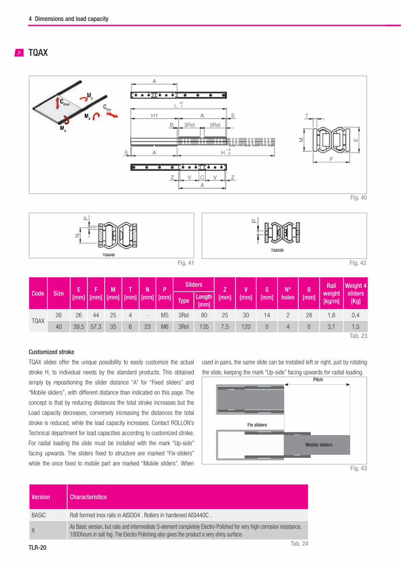
TLR-20
TQAX
TQAX26TQAX40
Code SizeE
[mm]F
[mm]M
[mm]T
[mm]N
[mm]P
[mm]
SlidersZ
[mm]V
[mm]S
[mm]N°
holesB
[mm]
Rail weight[kg/m]
Weight 4 sliders
[Kg]TypeLength [mm]
TQAX26 26 44 25 4 - M5 3Rol 80 25 30 14 2 28 1,6 0,4
40 39,5 57,3 35 6 23 M6 3Rol 135 7,5 120 0 4 0 3,1 1,5
Customized stroke
TQAX slides offer the unique possibility to easily customize the actual
stroke H, to individual needs by the standard products. This obtained
simply by repositioning the slider distance “A” for “Fixed sliders” and
“Mobile sliders”, with different distance than indicated on this page. The
concept is that by reducing distances the total stroke increases but the
Load capacity decreases, conversely increasing the distances the total
stroke is reduced, while the load capacity increases. Contact ROLLON’s
Technical department for load capacities according to customized stroke.
For radial loading the slide must be installed with the mark “Up-side”
facing upwards. The sliders fi xed to structure are marked “Fix-sliders”
while the once fi xed to mobile part are marked “Mobile sliders”. When
Tab. 23
Fig. 40
Fig. 42Fig. 41
Fig. 43
used in pairs, the same slide can be installed left or right, just by rotating
the slide, keeping the mark “Up-side” facing upwards for radial loading.
Version Characteristics
BASIC Roll formed inox rails in AISI304 . Rollers in hardened AISI440C .
XAs Basic version, but rails and intermediate S-element completely Electro-Polished for very high corrosion resistance,1000hours in salt fog. The Electro Polishing also gives the product a very shiny surface.
4 Dimensions and load capacity
Tab. 24
C0ax
Mz
My
Mx
0ax
MMz
MMx
MyC0radC
Mobile sliders
Pitch
Fix sliders
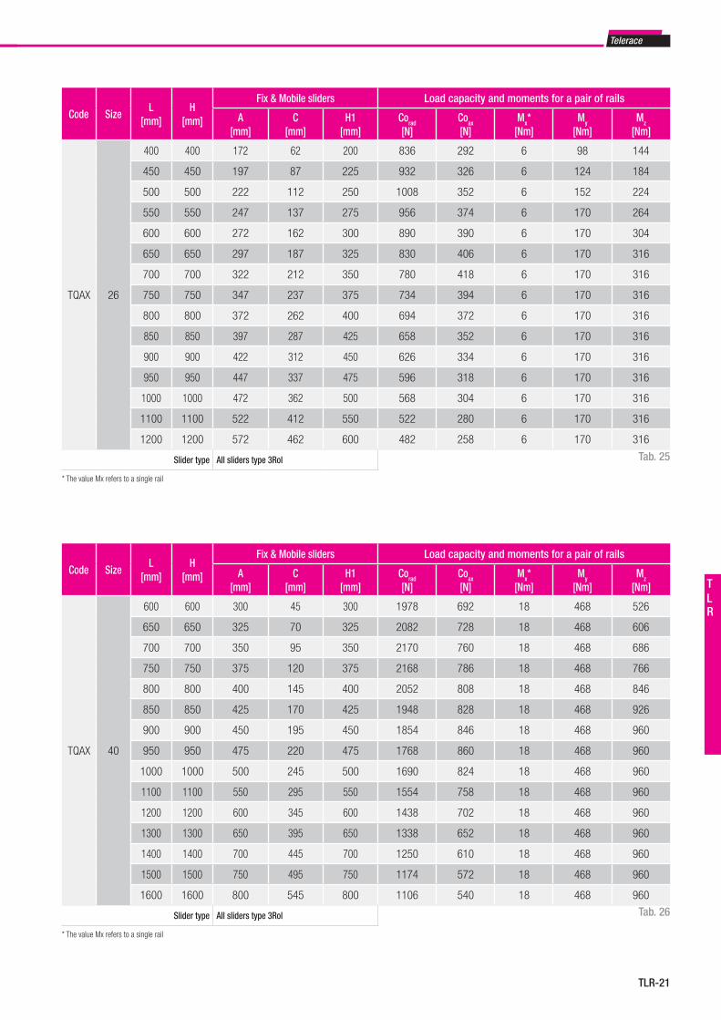
Telerace
TLR-21
TLR
Code SizeL
[mm]H
[mm]
Fix & Mobile sliders Load capacity and moments for a pair of rails
A[mm]
C[mm]
H1[mm]
Corad
[N]Coax
[N]Mx*
[Nm]My
[Nm]Mz
[Nm]
TQAX 26
400 400 172 62 200 836 292 6 98 144
450 450 197 87 225 932 326 6 124 184
500 500 222 112 250 1008 352 6 152 224
550 550 247 137 275 956 374 6 170 264
600 600 272 162 300 890 390 6 170 304
650 650 297 187 325 830 406 6 170 316
700 700 322 212 350 780 418 6 170 316
750 750 347 237 375 734 394 6 170 316
800 800 372 262 400 694 372 6 170 316
850 850 397 287 425 658 352 6 170 316
900 900 422 312 450 626 334 6 170 316
950 950 447 337 475 596 318 6 170 316
1000 1000 472 362 500 568 304 6 170 316
1100 1100 522 412 550 522 280 6 170 316
1200 1200 572 462 600 482 258 6 170 316
Slider type All sliders type 3Rol Tab. 25
* The value Mx refers to a single rail
Code SizeL
[mm]H
[mm]
Fix & Mobile sliders Load capacity and moments for a pair of rails
A[mm]
C[mm]
H1[mm]
Corad
[N]Coax
[N]Mx*
[Nm]My
[Nm]Mz
[Nm]
TQAX 40
600 600 300 45 300 1978 692 18 468 526
650 650 325 70 325 2082 728 18 468 606
700 700 350 95 350 2170 760 18 468 686
750 750 375 120 375 2168 786 18 468 766
800 800 400 145 400 2052 808 18 468 846
850 850 425 170 425 1948 828 18 468 926
900 900 450 195 450 1854 846 18 468 960
950 950 475 220 475 1768 860 18 468 960
1000 1000 500 245 500 1690 824 18 468 960
1100 1100 550 295 550 1554 758 18 468 960
1200 1200 600 345 600 1438 702 18 468 960
1300 1300 650 395 650 1338 652 18 468 960
1400 1400 700 445 700 1250 610 18 468 960
1500 1500 750 495 750 1174 572 18 468 960
1600 1600 800 545 800 1106 540 18 468 960
Slider type All sliders type 3Rol Tab. 26
* The value Mx refers to a single rail
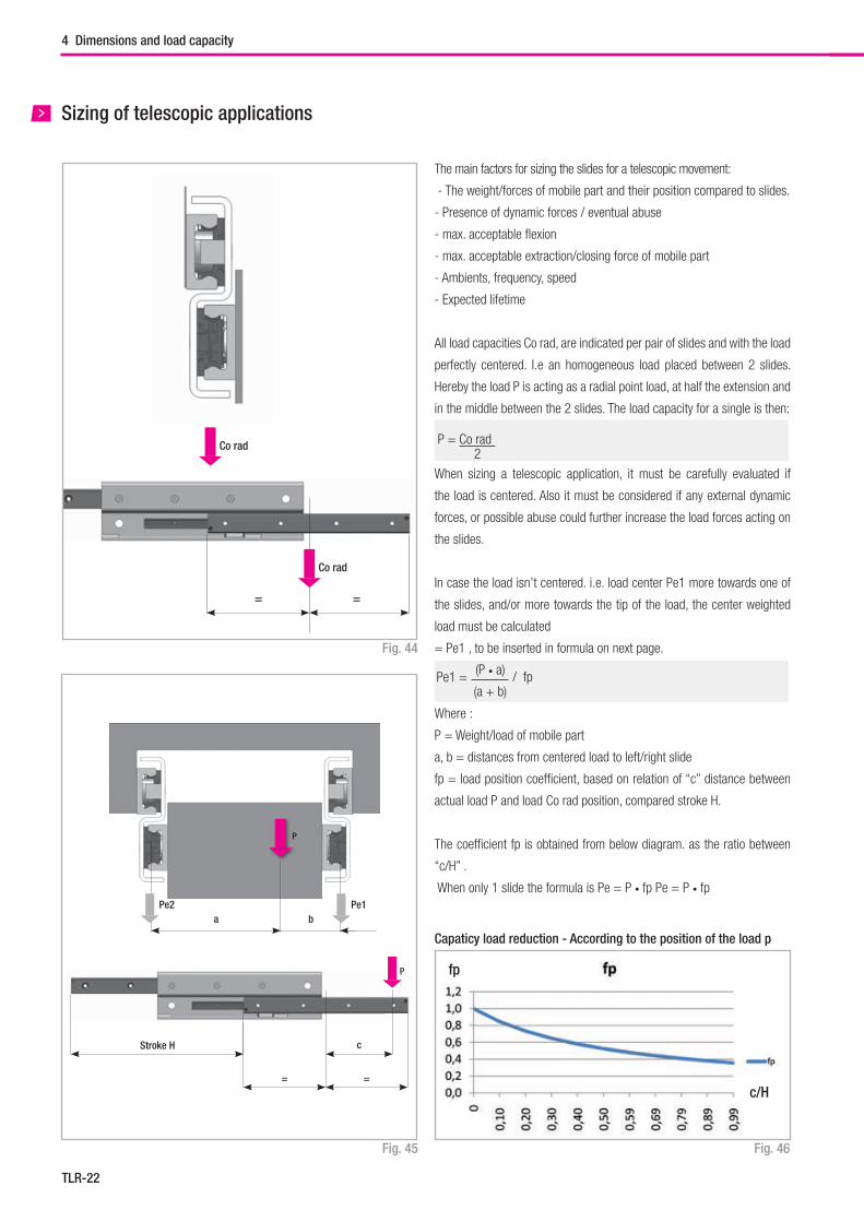
TLR-22
Sizing of telescopic applications
Co rad
= =
Co rad
P
P
Pe2 Pe1a
Stroke H c
= =
b
The main factors for sizing the slides for a telescopic movement:
- The weight/forces of mobile part and their position compared to slides.
- Presence of dynamic forces / eventual abuse
- max. acceptable fl exion
- max. acceptable extraction/closing force of mobile part
- Ambients, frequency, speed
- Expected lifetime
All load capacities Co rad, are indicated per pair of slides and with the load
perfectly centered. I.e an homogeneous load placed between 2 slides.
Hereby the load P is acting as a radial point load, at half the extension and
in the middle between the 2 slides. The load capacity for a single is then:
When sizing a telescopic application, it must be carefully evaluated if
the load is centered. Also it must be considered if any external dynamic
forces, or possible abuse could further increase the load forces acting on
the slides.
In case the load isn’t centered. i.e. load center Pe1 more towards one of
the slides, and/or more towards the tip of the load, the center weighted
load must be calculated
= Pe1 , to be inserted in formula on next page.
Where :
P = Weight/load of mobile part
a, b = distances from centered load to left/right slide
fp = load position coeffi cient, based on relation of “c” distance between
actual load P and load Co rad position, compared stroke H.
The coeffi cient fp is obtained from below diagram. as the ratio between
“c/H” .
When only 1 slide the formula is Pe = P • fp Pe = P • fp
(P • a)
(a + b)Pe1 = / fp
c/H
fp
Capaticy load reduction - According to the position of the load p
4 Dimensions and load capacity
Fig. 44
Fig. 45 Fig. 46
P = Co rad 2
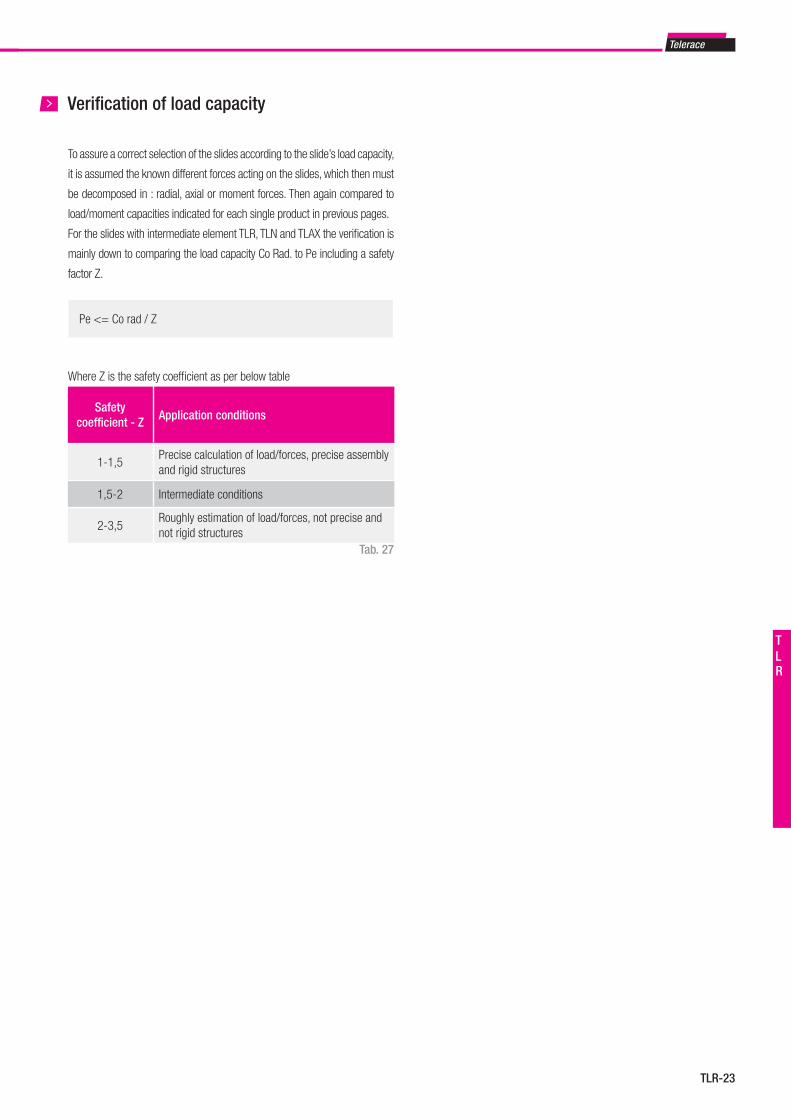
Telerace
TLR-23
TLR
Capaticy load reduction - According to the position of the load p
Verification of load capacity
To assure a correct selection of the slides according to the slide’s load capacity,
it is assumed the known different forces acting on the slides, which then must
be decomposed in : radial, axial or moment forces. Then again compared to
load/moment capacities indicated for each single product in previous pages.
For the slides with intermediate element TLR, TLN and TLAX the verification is
mainly down to comparing the load capacity Co Rad. to Pe including a safety
factor Z.
Pe <= Co rad / Z
Where Z is the safety coefficient as per below table
Safety coefficient - Z Application conditions
1-1,5Precise calculation of load/forces, precise assembly and rigid structures
1,5-2 Intermediate conditions
2-3,5Roughly estimation of load/forces, not precise and not rigid structures
Tab. 27
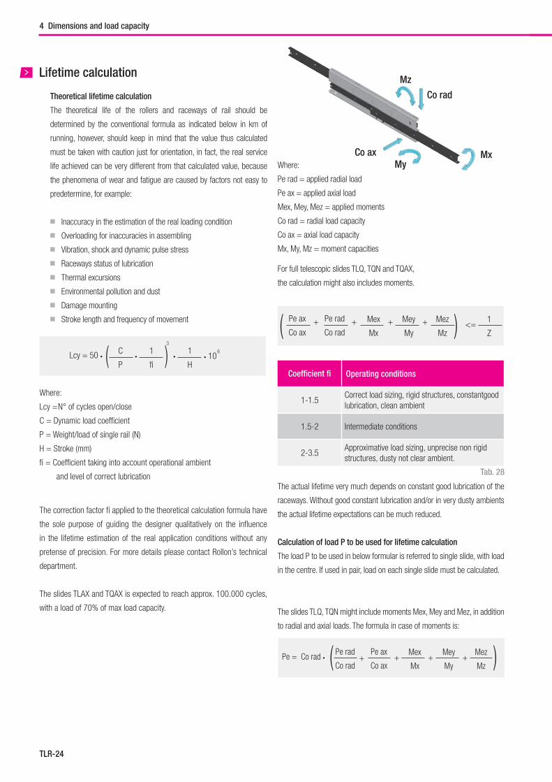
TLR-24
Coefficient fi Operating conditions
1-1.5Correct load sizing, rigid structures, constantgood lubrication, clean ambient
1.5-2 Intermediate conditions
2-3.5Approximative load sizing, unprecise non rigid structures, dusty not clear ambient.
Where:
Pe rad = applied radial load
Pe ax = applied axial load
Mex, Mey, Mez = applied moments
Co rad = radial load capacity
Co ax = axial load capacity
Mx, My, Mz = moment capacities
Co rad
Co axMy
Mx
Mz
For full telescopic slides TLQ, TQN and TQAX,
the calculation might also includes moments.
( )Pe rad
Co rad
Pe ax
Co ax
Mex
Mx
Mey
My
Mez
Mz
1
Z++ + + <=
The actual lifetime very much depends on constant good lubrication of the
raceways. Without good constant lubrication and/or in very dusty ambients
the actual lifetime expectations can be much reduced.
Calculation of load P to be used for lifetime calculation
The load P to be used in below formular is referred to single slide, with load
in the centre. If used in pair, load on each single slide must be calculated.
The slides TLQ, TQN might include moments Mex, Mey and Mez, in addition
to radial and axial loads. The formula in case of moments is:
( )Pe = Co rad • Mex
Mx
Mey
My
Mez
Mz+ ++
Pe rad
Co rad
Pe ax
Co ax+
Lifetime calculation
Theoretical lifetime calculation
The theoretical life of the rollers and raceways of rail should be
determined by the conventional formula as indicated below in km of
running, however, should keep in mind that the value thus calculated
must be taken with caution just for orientation, in fact, the real service
life achieved can be very different from that calculated value, because
the phenomena of wear and fatigue are caused by factors not easy to
predetermine, for example:
■ Inaccuracy in the estimation of the real loading condition
■ Overloading for inaccuracies in assembling
■ Vibration, shock and dynamic pulse stress
■ Raceways status of lubrication
■ Thermal excursions
■ Environmental pollution and dust
■ Damage mounting
■ Stroke length and frequency of movement
( )Lcy = 50 • C
P
3
1
H•
1
fi• • 10
6
The correction factor fi applied to the theoretical calculation formula have
the sole purpose of guiding the designer qualitatively on the influence
in the lifetime estimation of the real application conditions without any
pretense of precision. For more details please contact Rollon’s technical
department.
The slides TLAX and TQAX is expected to reach approx. 100.000 cycles,
with a load of 70% of max load capacity.
Where:
Lcy = N° of cycles open/close
C = Dynamic load coefficient
P = Weight/load of single rail (N)
H = Stroke (mm)
fi = Coefficient taking into account operational ambient
and level of correct lubrication
4 Dimensions and load capacity
Tab. 28
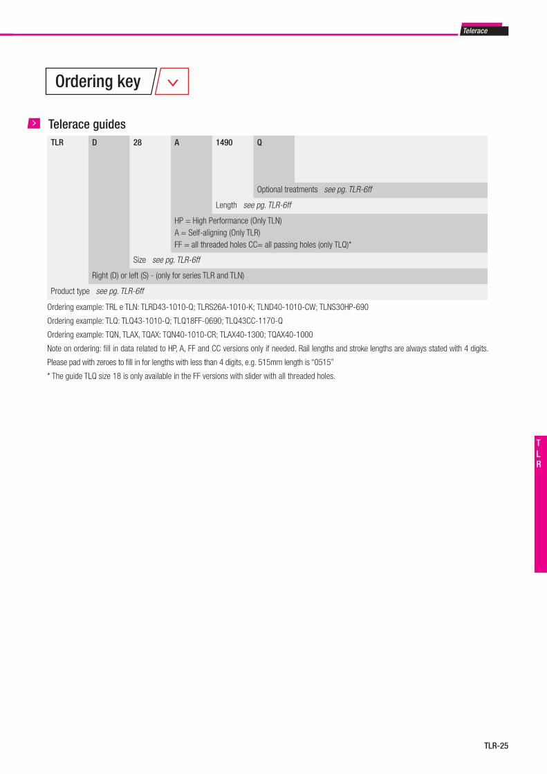
Telerace
TLR-25
TLR
TLR D 28 A 1490 Q
Optional treatments see pg. TLR-6ff
Length see pg. TLR-6ff
HP = High Performance (Only TLN)A = Self-aligning (Only TLR)FF = all threaded holes CC= all passing holes (only TLQ)*
Size see pg. TLR-6ff
Right (D) or left (S) - (only for series TLR and TLN)
Product type see pg. TLR-6ff
Telerace guides
Ordering example: TRL e TLN: TLRD43-1010-Q; TLRS26A-1010-K; TLND40-1010-CW; TLNS30HP-690
Ordering example: TLQ: TLQ43-1010-Q; TLQ18FF-0690; TLQ43CC-1170-Q
Ordering example: TQN, TLAX, TQAX: TQN40-1010-CR; TLAX40-1300; TQAX40-1000
Note on ordering: fill in data related to HP, A, FF and CC versions only if needed. Rail lengths and stroke lengths are always stated with 4 digits.
Please pad with zeroes to fill in for lengths with less than 4 digits, e.g. 515mm length is “0515”
* The guide TLQ size 18 is only available in the FF versions with slider with all threaded holes.
Ordering key

Light Rail
FrontespizioLightrail.indd 1 28/09/2018 13:18:15
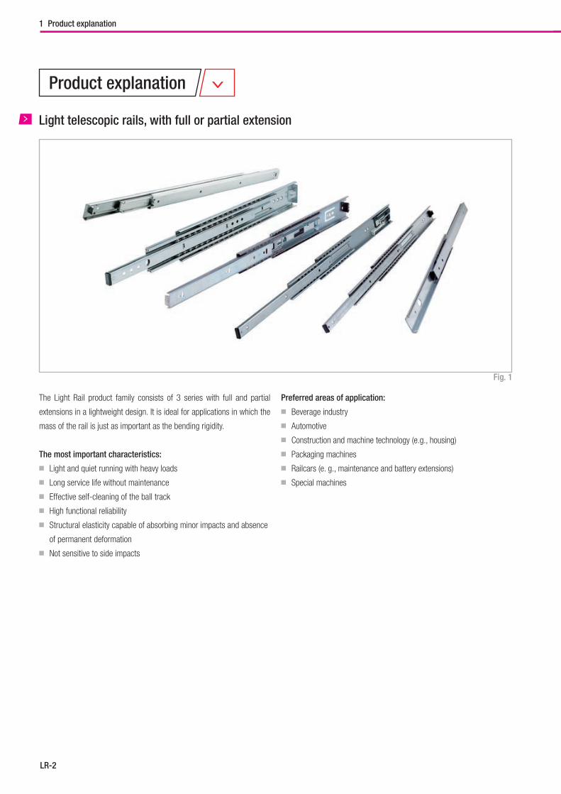
LR-2
Light telescopic rails, with full or partial extension
The Light Rail product family consists of 3 series with full and partial
extensions in a lightweight design. It is ideal for applications in which the
mass of the rail is just as important as the bending rigidity.
The most important characteristics:
■ Light and quiet running with heavy loads
■ Long service life without maintenance
■ Effective self-cleaning of the ball track
■ High functional reliability
■ Structural elasticity capable of absorbing minor impacts and absence
of permanent deformation
■ Not sensitive to side impacts
Preferred areas of application:
■ Beverage industry
■ Automotive
■ Construction and machine technology (e.g., housing)
■ Packaging machines
■ Railcars (e. g., maintenance and battery extensions)
■ Special machines
1 Product explanation
Product explanation
Fig. 1
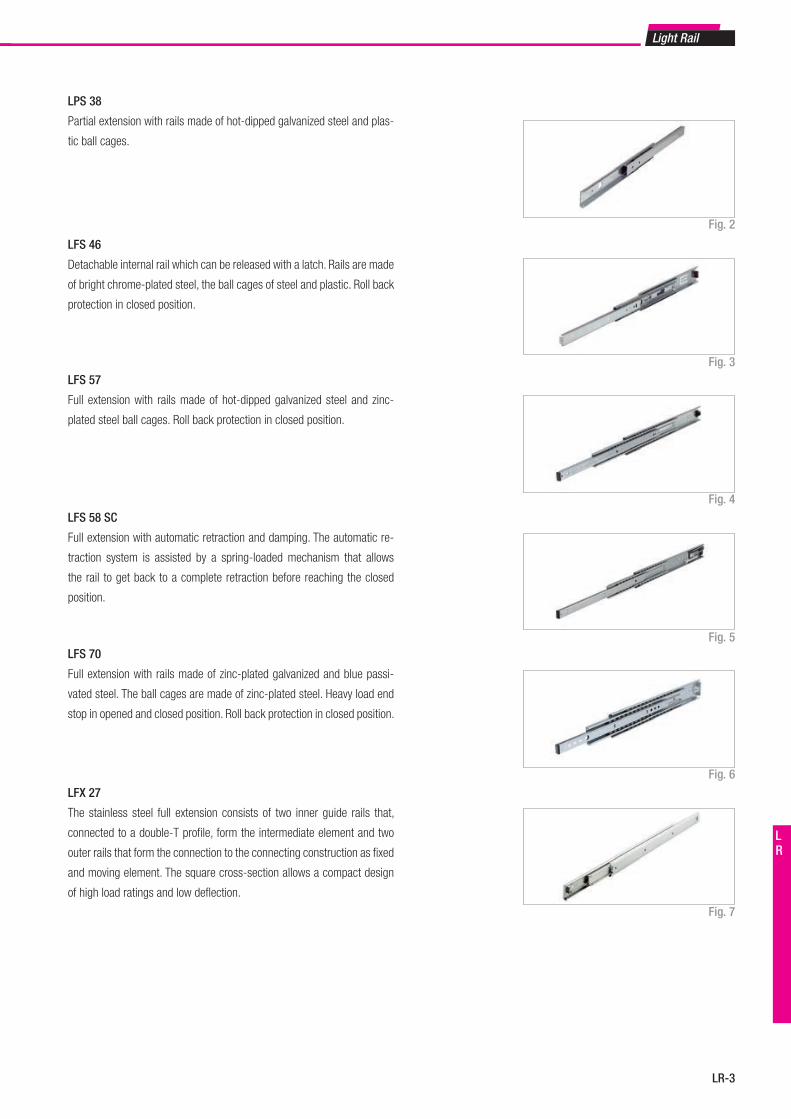
Light Rail
LR-3
LR
LPS 38
Partial extension with rails made of hot-dipped galvanized steel and plas-
tic ball cages.
LFS 46
Detachable internal rail which can be released with a latch. Rails are made
of bright chrome-plated steel, the ball cages of steel and plastic. Roll back
protection in closed position.
LFS 57
Full extension with rails made of hot-dipped galvanized steel and zinc-
plated steel ball cages. Roll back protection in closed position.
LFS 58 SC
Full extension with automatic retraction and damping. The automatic re-
traction system is assisted by a spring-loaded mechanism that allows
the rail to get back to a complete retraction before reaching the closed
position.
LFS 70
Full extension with rails made of zinc-plated galvanized and blue passi-
vated steel. The ball cages are made of zinc-plated steel. Heavy load end
stop in opened and closed position. Roll back protection in closed position.
LFX 27
The stainless steel full extension consists of two inner guide rails that,
connected to a double-T profile, form the intermediate element and two
outer rails that form the connection to the connecting construction as fixed
and moving element. The square cross-section allows a compact design
of high load ratings and low deflection.
Fig. 2
Fig. 3
Fig. 4
Fig. 5
Fig. 6
Fig. 7
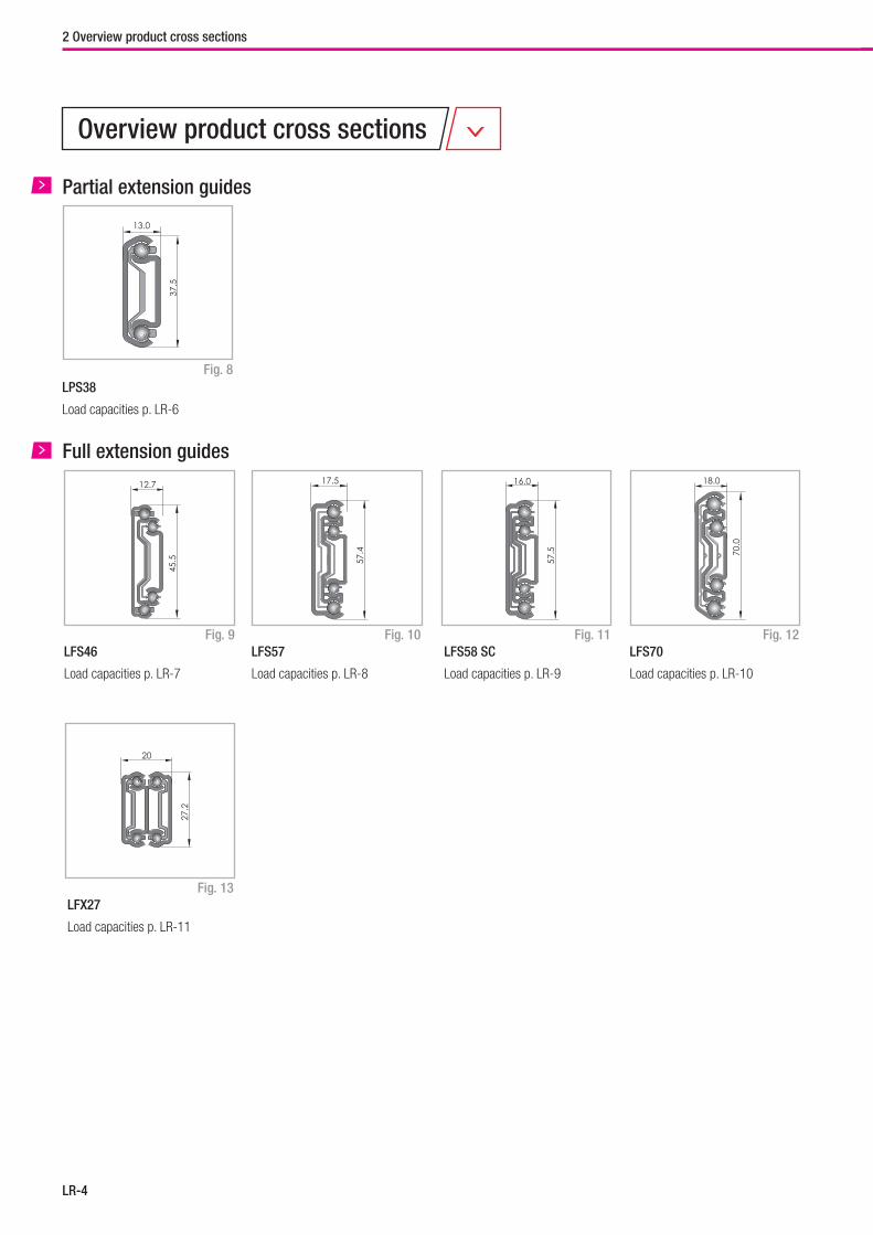
LR-4
Overview product cross sections
LPS38
Load capacities p. LR-6
Fig. 8
Partial extension guides
LFS58 SC
Load capacities p. LR-9
Fig. 9
Full extension guides
Fig. 11
Fig. 13
LFS46
Load capacities p. LR-7
LFX27
Load capacities p. LR-11
Fig. 12LFS70
Load capacities p. LR-10
Fig. 10LFS57
Load capacities p. LR-8
2 Overview product cross sections
37.5
13.0
45.5
27.2
12.7
20
57.4
57.5 70
.0
17.5 16.0 18.0
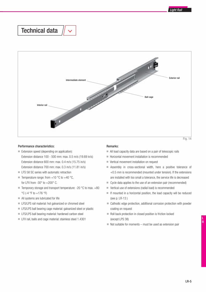
Light Rail
LR-5
LR
Performance characteristics:
■ Extension speed (depending on application):
Extension distance 100 - 500 mm: max. 0.5 m/s ( 19.69 in/s )
Extension distance 600 mm: max. 0.4 m/s ( 15.75 in/s )
Extension distance 700 mm: max. 0.3 m/s ( 11.81 in/s )
■ LFS 58 SC series with automatic retraction
■ Temperature range: from +10 °C to +40 °C,
for LFX from -30° to +200° C.
■ Temporary storage and transport temperature: -20 °C to max. +80
°C (-4 °F to +176 °F)
■ All systems are lubricated for life
■ LFS/LPS rail material: hot galvanized or chromed steel
■ LFS/LPS ball bearing cage material: galvanized steel or plastic
■ LFS/LPS ball bearing material: hardened carbon steel
■ LFX rail, balls and cage material: stainless steel 1.4301
Remarks:
■ All load capacity data are based on a pair of telescopic rails
■ Horizontal movement installation is recommended
■ Vertical movement installation on request
■ Assembly in cross-sectional width, here a positive tolerance of
+0.5 mm is recommended (mounted under tension). If the extensions
are installed with too small a tolerance, the service life is decreased
■ Cycle data applies to the use of an extension pair (recommended)
■ Vertical use of extensions (radial load) is recommended
■ If mounted in a horizontal position, the load capacity will be reduced
(see p. LR-13 )
■ Cathodic edge protection, additional corrosion protection with powder
coating on request
■ Roll back protection in closed position is friction locked
(except LPS 38)
■ Not suitable for moments – must be used as extension pair
Fig. 14
Interior rail
Intermediate element
Ball cage
Exterior rail
Technical data
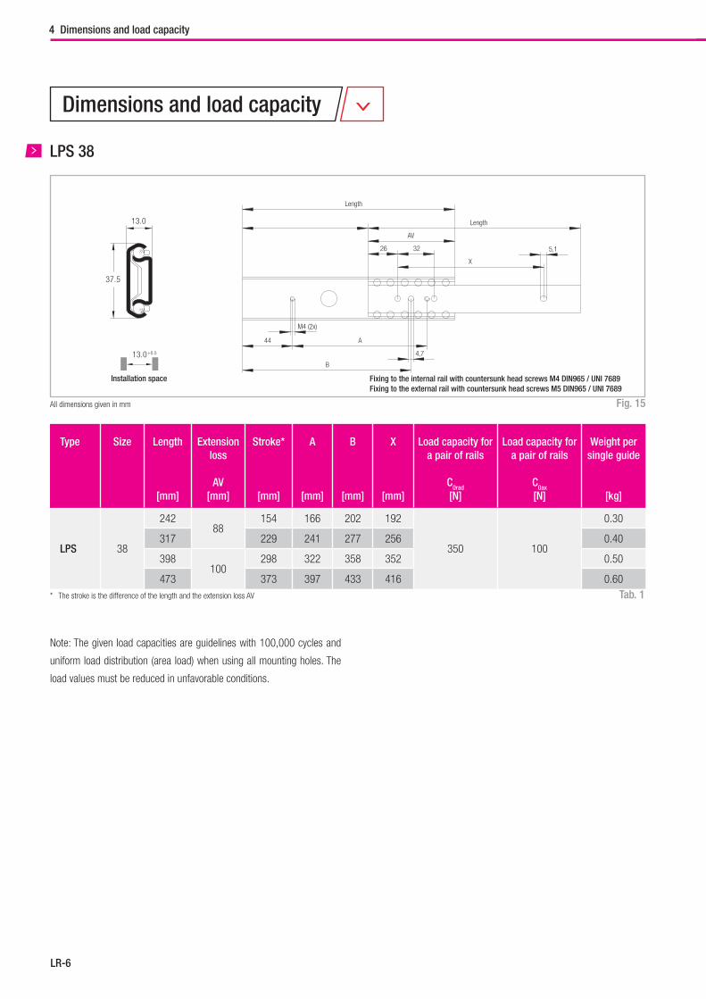
LR-6
LPS 38
Fig. 15
Tab. 1
All dimensions given in mm
Type Size Length
[mm]
Extension loss
AV[mm]
Stroke*
[mm]
A
[mm]
B
[mm]
X
[mm]
Load capacity for a pair of rails
C0rad
[N]
Load capacity for a pair of rails
C0ax
[N]
Weight per single guide
[kg]
LPS 38
24288
154 166 202 192
350 100
0.30
317 229 241 277 256 0.40
398100
298 322 358 352 0.50
473 373 397 433 416 0.60* The stroke is the difference of the length and the extension loss AV
Note: The given load capacities are guidelines with 100,000 cycles and
uniform load distribution (area load) when using all mounting holes. The
load values must be reduced in unfavorable conditions.
13.0
37.5
13.0+0.5
Installation space
5,126 32
AV
Length
X
Length
44
B
A
M4 (2x)
4,7
Fixing to the internal rail with countersunk head screws M4 DIN965 / UNI 7689Fixing to the external rail with countersunk head screws M5 DIN965 / UNI 7689
4 Dimensions and load capacity
Dimensions and load capacity
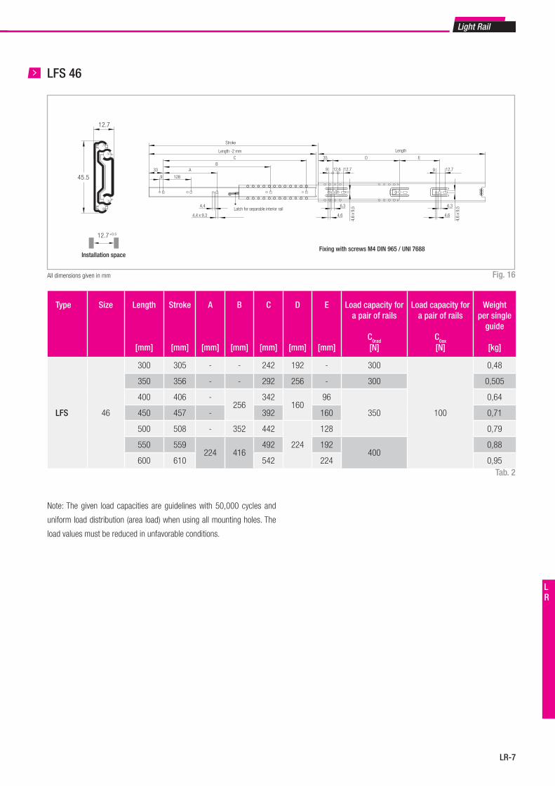
Light Rail
LR-7
LR
Fig. 16
LFS 46
All dimensions given in mm
Note: The given load capacities are guidelines with 50,000 cycles and
uniform load distribution (area load) when using all mounting holes. The
load values must be reduced in unfavorable conditions.
Tab. 2
12.7
45.5
12.7+0.5
Installation space
Length -2 mm
Stroke
CB
A
4,4
4,4 x 9,3
33
9 128
35 D E
9 12,712,6
4,6
x 9,
5
Length
9 12,7
Latch for separable interior rail6,3 6,3
4,6 4,6
4,6
x 9,
5
Fixing with screws M4 DIN 965 / UNI 7688
Type Size Length
[mm]
Stroke
[mm]
A
[mm]
B
[mm]
C
[mm]
D
[mm]
E
[mm]
Load capacity for a pair of rails
C0rad
[N]
Load capacity for a pair of rails
C0ax
[N]
Weight per single
guide
[kg]
LFS 46
300 305 - - 242 192 - 300
100
0,48
350 356 - - 292 256 - 300 0,505
400 406 -256
342160
96
350
0,64
450 457 - 392 160 0,71
500 508 - 352 442
224
128 0,79
550 559224 416
492 192400
0,88
600 610 542 224 0,95
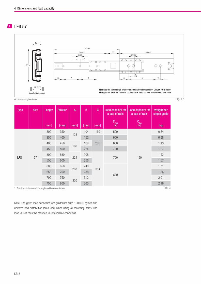
LR-8
4 Dimensions and load capacity
Fig. 17
Tab. 3
LFS 57
All dimensions given in mm
Type Size Length
[mm]
Stroke*
[mm]
A
[mm]
B
[mm]
C
[mm]
Load capacity for a pair of rails
C0rad
[N]
Load capacity for a pair of rails
C0ax
[N]
Weight per single guide
[kg]
LFS 57
300 350128
104 160 500
160
0.84
350 400 152
256
600 0.98
400 450160
168 650 1.13
450 500 224 700 1.27
500 550224
208
384
7501.42
550 600 256 1.57
600 650288
240
800
1.71
650 700 288 1.86
700 750320
312 2.01
750 800 360 2.16
Note: The given load capacities are guidelines with 100,000 cycles and
uniform load distribution (area load) when using all mounting holes. The
load values must be reduced in unfavorable conditions.
* The stroke is the sum of the length and the over extension
17.5
57.4
17.5+0.5
Installation space
BA
Length
Stroke
50
5,1
8/90° 9,5/90°
6,5
Length
16C3232
Fixing to the internal rail with countersunk head screws M4 DIN966 / UNI 7689Fixing to the external rail with countersunk head screws M5 DIN966 / UNI 7689
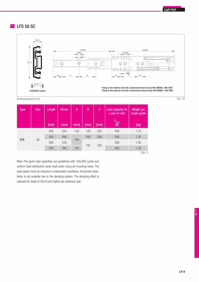
Light Rail
LR-9
LR
Fig. 18
Tab. 4
LFS 58 SC
All dimensions given in mm
Type Size Length
[mm]
Stroke
[mm]
A
[mm]
B
[mm]
C
[mm]
Load capacity for a pair of rails
C0rad
[N]
Weight per single guide
[kg]
LFS 58
400 434 128 128 224 400 1.10
450 484160
160 256 500 1.25
500 534192 320
550 1.40
550 584 192 600 1.55
Note: The given load capacities are guidelines with 100,000 cycles and
uniform load distribution (area load) when using all mounting holes. The
load values must be reduced in unfavorable conditions. Horizontal instal-
lation is not possible due to the damping system. The damping effect is
reduced for loads of 450 N and higher per extension pair.
16.0
57.5
16.0+0.5
BA32
Stroke
5,1
8/90° 9,5/90°
6,5
Length
16C32
Installation spaceFixing to the internal rail with countersunk head screws M4 DIN966 / UNI 7689Fixing to the external rail with countersunk head screws M5 DIN966 / UNI 7689
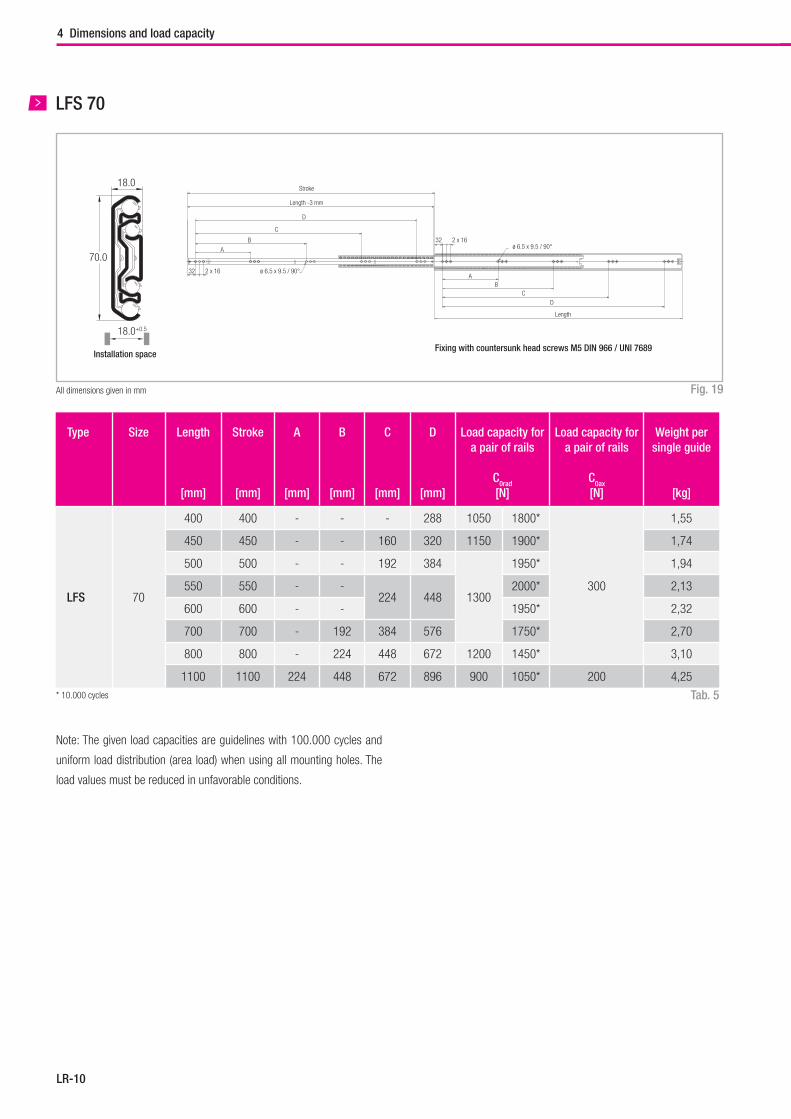
LR-10
4 Dimensions and load capacity
Fig. 19
Tab. 5
LFS 70
All dimensions given in mm
Note: The given load capacities are guidelines with 100.000 cycles and
uniform load distribution (area load) when using all mounting holes. The
load values must be reduced in unfavorable conditions.
* 10.000 cycles
18.0
70.0
18.0+0.5
Stroke
Length -3 mm
D
C
B
A
32 2 x 16 ø 6.5 x 9.5 / 90°
32 2 x 16ø 6.5 x 9.5 / 90°
AB
CD
Length
Installation spaceFixing with countersunk head screws M5 DIN 966 / UNI 7689
Type Size Length
[mm]
Stroke
[mm]
A
[mm]
B
[mm]
C
[mm]
D
[mm]
Load capacity for a pair of rails
C0rad
[N]
Load capacity for a pair of rails
C0ax
[N]
Weight per single guide
[kg]
LFS 70
400 400 - - - 288 1050 1800*
300
1,55
450 450 - - 160 320 1150 1900* 1,74
500 500 - - 192 384
1300
1950* 1,94
550 550 - -224 448
2000* 2,13
600 600 - - 1950* 2,32
700 700 - 192 384 576 1750* 2,70
800 800 - 224 448 672 1200 1450* 3,10
1100 1100 224 448 672 896 900 1050* 200 4,25
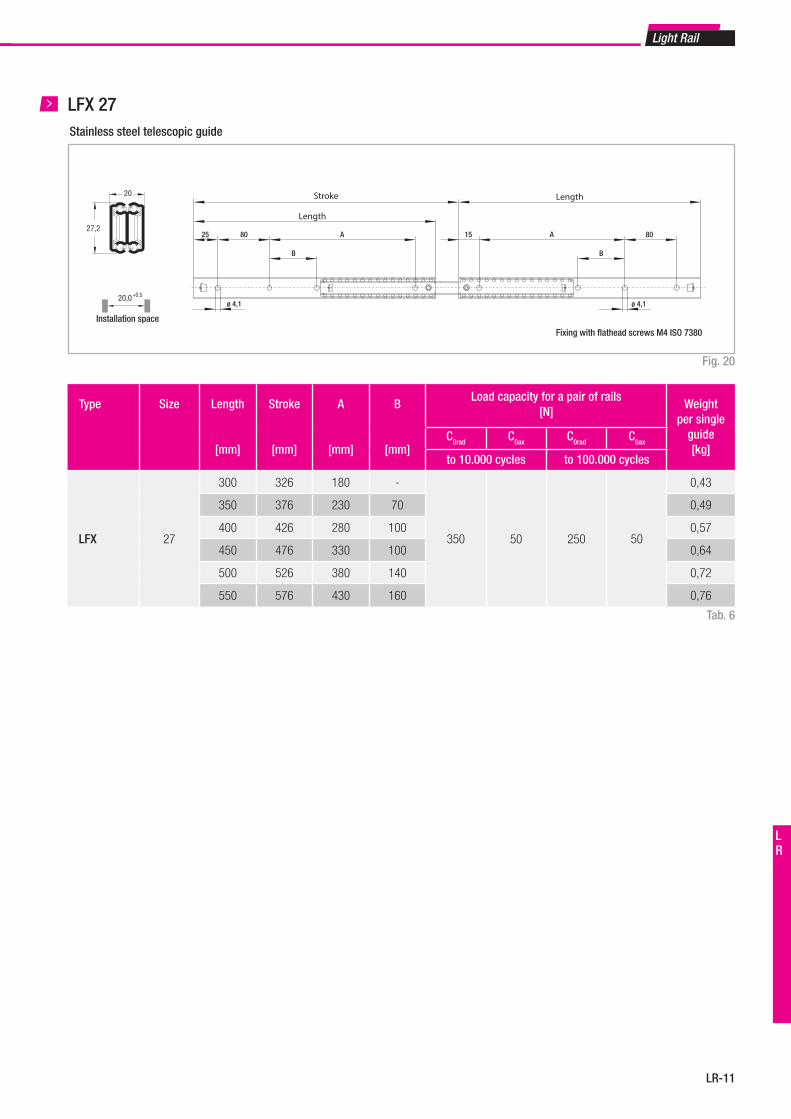
Light Rail
LR-11
LR
LFX 27
Fig. 20
Tab. 6
Länge
25
Länge
B
80 A
ø 4,1
15
B
80A
ø 4,1
Hub
Type Size Length
[mm]
Stroke
[mm]
A
[mm]
B
[mm]
Load capacity for a pair of rails[N]
Weight per single
guide[kg]
C0rad C0ax C0rad C0ax
to 10.000 cycles to 100.000 cycles
LFX 27
300 326 180 -
350 50 250 50
0,43
350 376 230 70 0,49
400 426 280 100 0,57
450 476 330 100 0,64
500 526 380 140 0,72
550 576 430 160 0,76
20,0+0,5
Einbauraum
27,2
20
Installation space
Length
Length
Stroke
Stainless steel telescopic guide
Fixing with flathead screws M4 ISO 7380
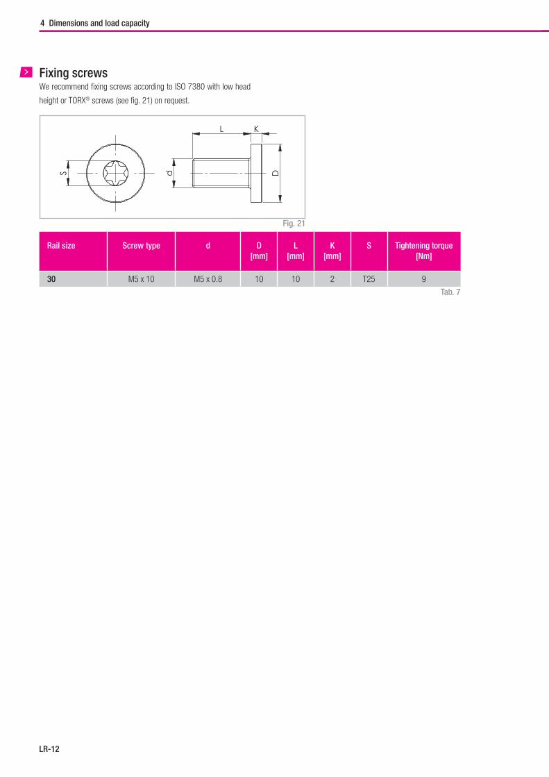
LR-12
4 Dimensions and load capacity
Fixing screwsWe recommend fixing screws according to ISO 7380 with low head
height or TORX® screws (see fig. 21) on request.
S d
L K
D
Rail size Screw type d D[mm]
L[mm]
K[mm]
S Tightening torque [Nm]
30 M5 x 10 M5 x 0.8 10 10 2 T25 9
Fig. 21
Tab. 7
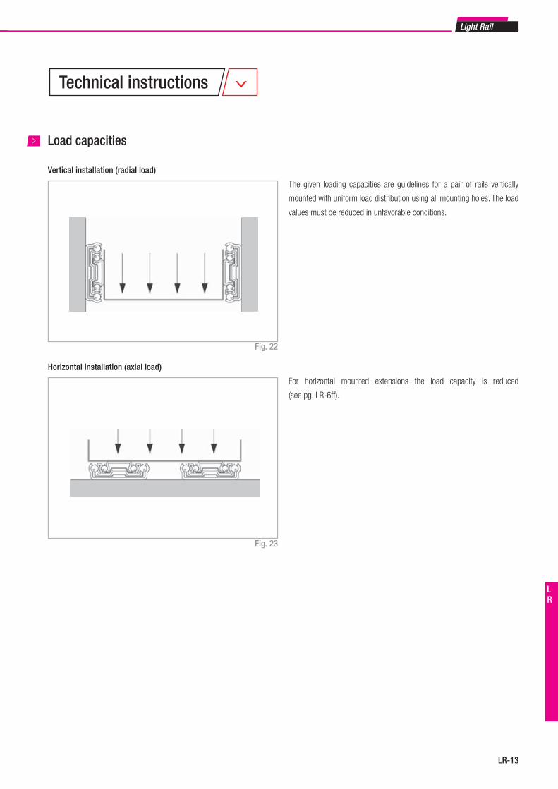
Light Rail
LR-13
LR
Horizontal installation (axial load)
Vertical installation (radial load)
Load capacities
Fig. 22
Fig. 23
The given loading capacities are guidelines for a pair of rails vertically
mounted with uniform load distribution using all mounting holes. The load
values must be reduced in unfavorable conditions.
For horizontal mounted extensions the load capacity is reduced
(see pg. LR-6ff).
Technical instructions
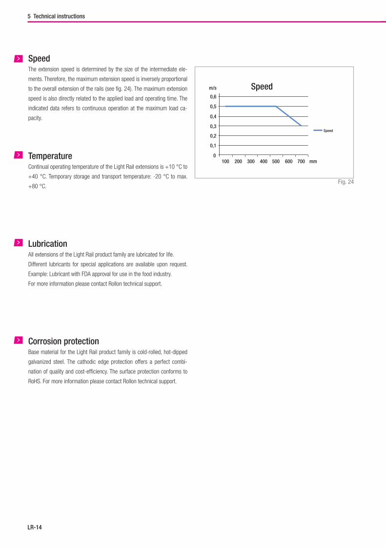
LR-14
All extensions of the Light Rail product family are lubricated for life.
Different lubricants for special applications are available upon request.
Example: Lubricant with FDA approval for use in the food industry.
For more information please contact Rollon technical support.
Lubrication
Base material for the Light Rail product family is cold-rolled, hot-dipped
galvanized steel. The cathodic edge protection offers a perfect combi-
nation of quality and cost-efficiency. The surface protection conforms to
RoHS. For more information please contact Rollon technical support.
Corrosion protection
Continual operating temperature of the Light Rail extensions is +10 °C to
+40 °C. Temporary storage and transport temperature: -20 °C to max.
+80 °C.
Temperature
The extension speed is determined by the size of the intermediate ele-
ments. Therefore, the maximum extension speed is inversely proportional
to the overall extension of the rails (see fig. 24). The maximum extension
speed is also directly related to the applied load and operating time. The
indicated data refers to continuous operation at the maximum load ca-
pacity.
Speed
Fig. 24
0
0,6
m/s
0,5
0,4
0,3
0,2
0,1
100 200 300 400 500 600 700 mm
Speed
Speed
5 Technical instructions
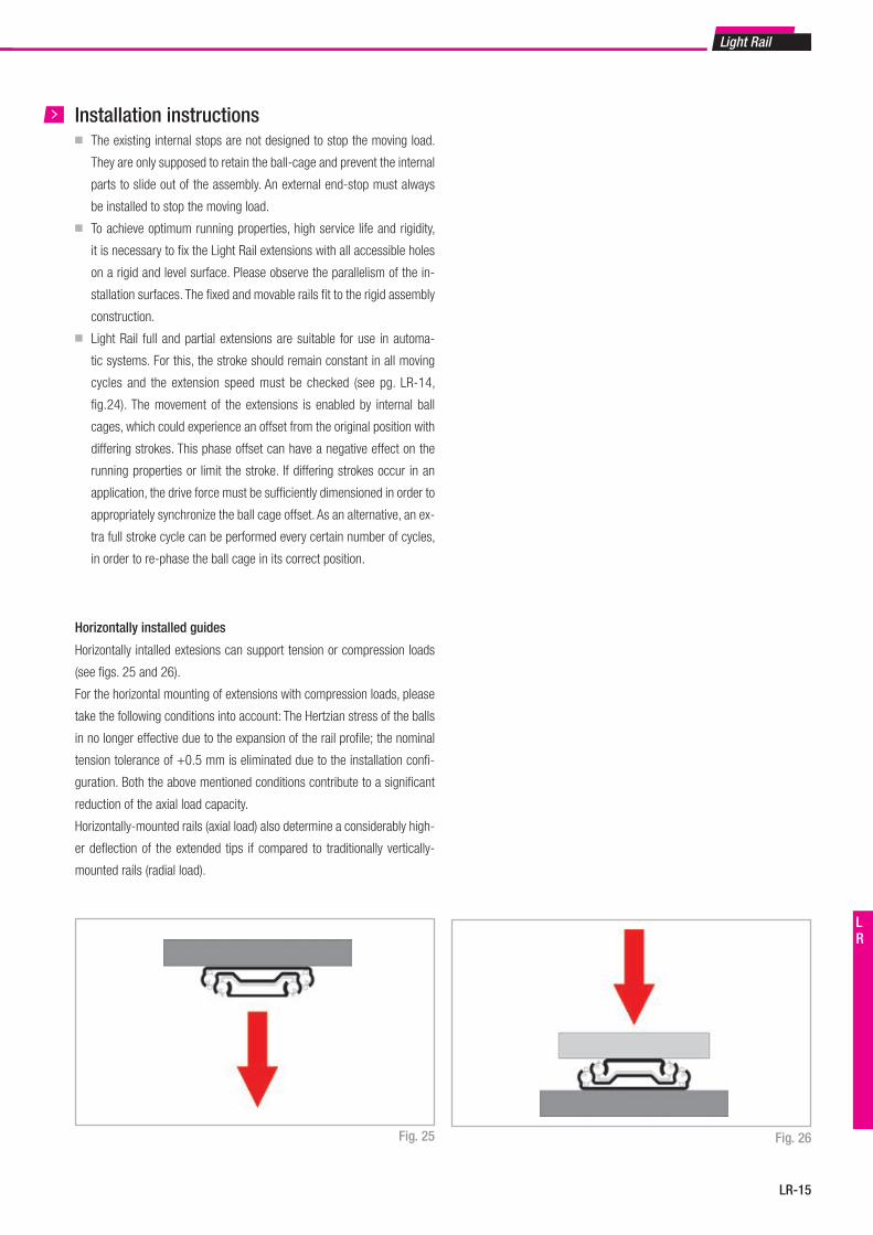
Light Rail
LR-15
LR
Fig. 25 Fig. 26
■ The existing internal stops are not designed to stop the moving load.
They are only supposed to retain the ball-cage and prevent the internal
parts to slide out of the assembly. An external end-stop must always
be installed to stop the moving load.
■ To achieve optimum running properties, high service life and rigidity,
it is necessary to fix the Light Rail extensions with all accessible holes
on a rigid and level surface. Please observe the parallelism of the in-
stallation surfaces. The fixed and movable rails fit to the rigid assembly
construction.
■ Light Rail full and partial extensions are suitable for use in automa-
tic systems. For this, the stroke should remain constant in all moving
cycles and the extension speed must be checked (see pg. LR-14,
fig.24). The movement of the extensions is enabled by internal ball
cages, which could experience an offset from the original position with
differing strokes. This phase offset can have a negative effect on the
running properties or limit the stroke. If differing strokes occur in an
application, the drive force must be sufficiently dimensioned in order to
appropriately synchronize the ball cage offset. As an alternative, an ex-
tra full stroke cycle can be performed every certain number of cycles,
in order to re-phase the ball cage in its correct position.
Installation instructions
Horizontally intalled extesions can support tension or compression loads
(see figs. 25 and 26).
For the horizontal mounting of extensions with compression loads, please
take the following conditions into account: The Hertzian stress of the balls
in no longer effective due to the expansion of the rail profile; the nominal
tension tolerance of +0.5 mm is eliminated due to the installation confi-
guration. Both the above mentioned conditions contribute to a significant
reduction of the axial load capacity.
Horizontally-mounted rails (axial load) also determine a considerably high-
er deflection of the extended tips if compared to traditionally vertically-
mounted rails (radial load).
Horizontally installed guides
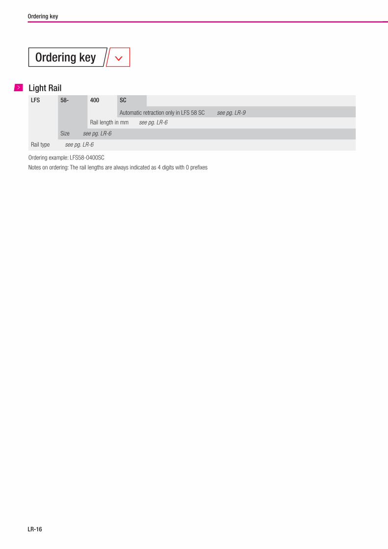
LR-16
Ordering key
LFS 58- 400 SC
Automatic retraction only in LFS 58 SC see pg. LR-9
Rail length in mm see pg. LR-6
Size see pg. LR-6
Rail type see pg. LR-6
Light Rail
Ordering example: LFS58-0400SC
Notes on ordering: The rail lengths are always indicated as 4 digits with 0 prefixes
Ordering key
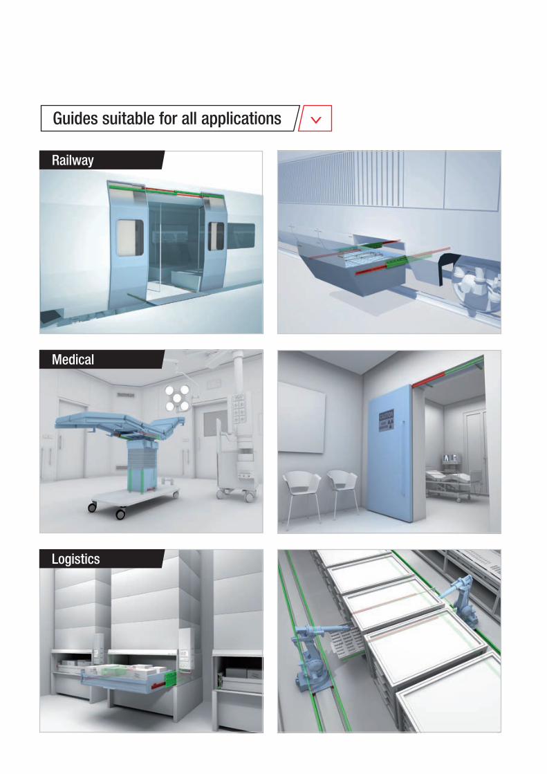
Railway
Medical
Logistics
Guides suitable for all applications
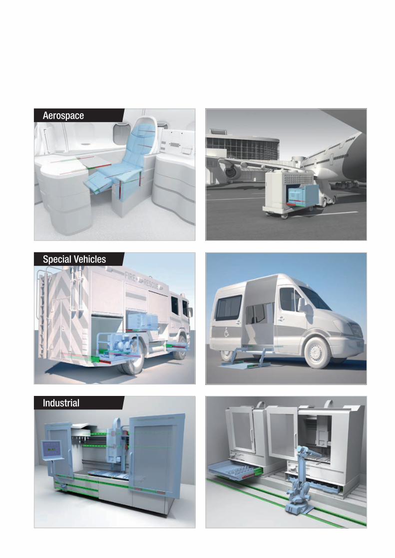
Aerospace
Special Vehicles
Industrial

DistributorConsult the other ranges of products
All addresses of our global sales partners can also be found at www.rollon.comThe content of this document and its use are subject to the general terms of sale of ROLLON available on the web site www.rollon.comChanges and errors expected. The text and images may be used only with our permission.
3F Shiodome Building, 1-2-20 Kaigan, Minato-ku,Tokyo 105-0022 JapanPhone +81 3 6721 8487www.rollon.jp - [email protected]
ROLLON - JAPAN
Via Trieste 26I-20871 Vimercate (MB)Phone: (+39) 039 62 59 1www.rollon.it - [email protected]
ROLLON S.p.A. - ITALY (Headquarters)
Bonner Strasse 317-319D-40589 DüsseldorfPhone: (+49) 211 95 747 0www.rollon.de - [email protected]
ROLLON GmbH - GERMANY
Ringbaan Zuid 86905 DB ZevenaarPhone: (+31) 316 581 999www.rollon.nl - [email protected]
ROLLON B.V. - NETHERLANDS
101 Bilby Road. Suite BHackettstown, NJ 07840Phone: (+1) 973 300 5492www.rolloncorp.com - [email protected]
ROLLON Corporation - USA
Les Jardins d‘Eole, 2 allée des SéquoiasF-69760 LimonestPhone: (+33) (0) 4 74 71 93 30www.rollon.fr - [email protected]
ROLLON S.A.R.L. - FRANCE
R. Joaquim Floriano, 397, 2o. andarItaim Bibi - 04534-011, São Paulo, BRASIL Phone: +55 (11) 3198 3645 www.rollonbrasil.com.br - [email protected]
ROLLON - SOUTH AMERICA (Rep. Office)
1st floor, Regus Gem Business Centre, 26/1 Hosur Road, Bommanahalli, Bangalore 560068Phone: (+91) 80 67027066www.rollonindia.in - [email protected]
ROLLON India Pvt. Ltd. - INDIA
117105, Moscow, Varshavskoyeshosse 17, building 1Phone: +7 (495) 508-10-70 www.rollon.ru - [email protected]
ROLLON S.p.A. - RUSSIA (Rep. Office)
No. 1155 Pang Jin Road, China, Suzhou, 215200Phone: +86 0512 6392 1625 www.rollon.cn.com - [email protected]
ROLLON Ltd - CHINA
The Works 6 West Street OlneyBuckinghamshire, United Kingdom, MK46 5 HRPhone: +44 (0) 1234964024www.rollon.uk.com - [email protected]
ROLLON Ltd - UK (Rep. Office)
ASIA
AMERICA
EUROPE
Linear Line
www.rollon.com
COVER_Linear.indd 1 28/09/2018 13:25:04
Telescopic Line
www.rollon.com
COVER_TELESCOPIC.indd 1 28/09/2018 13:25:34
Actuator System Line
www.rollon.com
COVE_ActuatorSystemLine.indd 1 28/09/2018 13:23:35
Actuator Line
www.rollon.com
COVER_Attuatori.indd 1 28/09/2018 13:24:25
Rollon Branches & Rep. OfficesDistributors
Follow us:
TL_GC_EN_02/19