Embed Size (px)
Citation preview
WIKA Alexander Wiegand GmbH & Co. KG Alexander-Wiegand-Straße 30 63911 Klingenberg/Germany Phone (+49) 93 72/132-0 Fax (+49) 93 72/132-406 E-Mail [email protected] www.wika.de
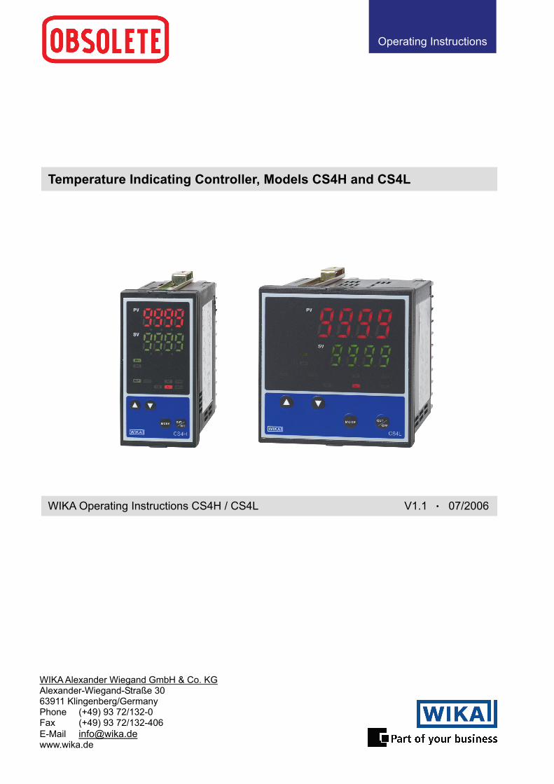
Temperature Indicating Controller, Models CS4H and CS4L
WIKA Operating Instructions CS4H / CS4L V1.1 • 07/2006
Operating Instructions
Operating Instructions Temperature Indicating Controller CS4H / CS4L
V1.1 • 05/2006 - 2 -
Preface Thank you for the purchase of our microcomputer based temperature indicating controllers CS4H or CS4L. This manual contains instructions for the mounting, functions, operations and notes when operating the CS4H or CS4L. For model confirmation and unit specifications, please read this manual carefully before starting operation. To prevent accidents arising from the misuse of this controller, please ensure the operator using it receives this manual.
Caution • This instrument should be used according to the specifications described in the manual.
If it is used according to the specifications, it may malfunction or cause fire. • Be sure to follow the warnings, cautions and notices. If not, it could cause serious injury or malfunction. • Specifications of the CS4H and CS4L and the contents of this instruction manual are subject to change
without notice. • Care has been taken to assure that the contents of this instruction manual are correct, but if there are any
doubts, mistakes or questions, please inform our sales department. • This instrument is designed to be installed in a control panel. If not, measures must be taken to ensure that
the operator cannot touch power terminals or other high voltage sections. • Any unauthorized transfer or copying of this document, in part or in whole, is prohibited. • WIKA is not liable for any damages or secondary damages incurred as a result of using this product, in-
cluding any indirect damages. SAFETY PRECAUTIONS (Be sure to read these precautions before using our products.) The safety precautions are classified into categories: “ Warning” and “ Caution”. Depending on circumstances, procedures indicated by “ Caution” may be linked to serious results, so be sure to follow the directions for usage.
Warning
Procedures, which may lead to dangerous conditions and cause death or serious injury, if not carried out properly.
Procedures which may lead to dangerous conditions and cause superficial to medium injury or physical damage or may degrade or damage the product, if not carried out properly.
Caution
Operating Instructions Temperature Indicating Controller CS4H / CS4L
V1.1 • 05/2006 - 3 -
1. Installation precautions
Caution This instrument is intended to be used under the following environmental conditions (IEC61010-1): Overvoltage category , Pollution degree 2 Mount the controller in a place with: • A minimum of dust, and an absense of corrosive gasses • No flammable, expolsive gasses • No mechanical vibrations or shocks • No exposure to direct sunlight, an ambient temperature of 0 ... 50°C (32 ... 122°F) that does
not change suddenly • An ambient non-condensing humidity of 35 ... 85%RH • No large capacity electromagnetic switches or cables through which large current is
flowing. • No water, oil or chemicals or where the vapors of these substances can come into direct
contact with the unit Note: Do not install this instrument near flammable material even though the case of this
instrument is made of flame resisting resin. Avoid setting this instrument directly on flammable material.
2. Wiring precautions
Caution • Use the solderless terminal with an insulation sleeve that fits in the M3 screw when wiring
the CS4H or CS4L. • The terminal block of this instrument is designed to be wired from the left side.
The lead wire must be inserted from the left side of the terminal, and fastened with the ter-minal screw.
• Tighten the terminal screw within the specified torque. If excessive force is applied to the screw when tightening, the screw or case may be dam-aged.
• Do not apply a commercial power source to the sensor which is connected to the input terminal nor allow the power source to come into contact with the sensor, as the input cir-cuit may be burnt out.
• This controller has no built-in power switch, circuit breaker or fuse. It is necessary to install them near the controller. (Recommended fuse: Time-lag fuse, rated voltage 250V AC, rated current 2A)
• When using a 24V AC/DC for the power source, do not confuse the polarity when it is DC. 3. Running and maintenance precautions
Caution • It is recommended that PID auto-tuning be performed on the trial run. • Do not touch live terminals. This may cause electric shock or problems in operation. • Turn the power supplied to the instrunment OFF when retightening the terminal and
cleaning. Working or touching the terminal with the power switched ON may result in Elec-tric Shock causing severe injury or death.
• Use a soft, dry cloth when cleaning the instrument. (If paint thinner is used, it might deform or tarnish the unit.)
• As the display section is vulnerable, do not strike or scratch it with a hard object or press hard on them
Operating Instructions Temperature Indicating Controller CS4H / CS4L
V1.1 • 05/2006 - 4 -
List of contents
1. Model informations 1.1 Model name ····················································································································· 6 1.2 Rated input ······················································································································· 7
2. Name and functions of the sections ········································································ 8 3. Mounting to control panel
3.1 Site selection ·················································································································· 10 3.2 External dimension ········································································································· 10 3.3 Panel cutout ····················································································································11 3.4 CT (current transformer) external dimension ···································································11 3.5 Mounting ························································································································ 12
4. Wiring connection 4.1 Terminal arrangement ···································································································· 13 4.2 Wiring connection example ···························································································· 14
5. Setup 5.1 Setup flow chart ············································································································· 17 5.2 Main setting mode
SV1 ································································································································· 19 SV2 ································································································································· 19
5.3 Sub setting mode AT setting/Auto-reset setting ··························································································· 19 OUT1 proportional band setting ······················································································ 19 OUT2 proportional band setting ······················································································ 19 Integral time setting ········································································································· 20 Derivative time setting ····································································································· 20 ARW (Anti-reset windup) setting ····················································································· 20 OUT1 proportional cycle setting ······················································································ 20 OUT2 proportional cycle setting ······················································································ 20 A1 setting ························································································································ 20 A2 setting ························································································································ 20 HB (Heater burnout alarm) setting ··················································································· 21 LA (Loop break alarm) action time setting ······································································· 21 LA (Loop break alarm) action span setting ······································································ 21
5.4 Auxiliary function setting mode 1 Setting value lock selection ····························································································· 22 SV high limit setting ········································································································· 22 SV low limit setting ·········································································································· 22 Sensor correction setting ································································································· 22 Communication protocol selection ··················································································· 22 Instrument number setting ······························································································· 22 Data transfer rate selection ····························································································· 23 Parity selection ················································································································ 23 Stop bit selection ············································································································· 23
5.5 Auxiliary function setting mode 2 Sensor selection ·············································································································· 24 Scaling high limit setting ·································································································· 24 Scaling low limit setting ··································································································· 24 Decimal point place selection ·························································································· 25 PV filter time constant setting ·························································································· 25 OUT1 high limit setting ···································································································· 25 OUT1 low limit setting ····································································································· 25 OUT1 ON/OFF action hysteresis setting ········································································· 25 OUT2 action mode selection ··························································································· 25 OUT2 high limit setting ···································································································· 25 OUT2 low limit setting ····································································································· 25 Overlap band/Dead band setting ····················································································· 26 OUT2 ON/OFF action hysteresis setting ········································································· 26 A1 action selection ·········································································································· 26
Operating Instructions Temperature Indicating Controller CS4H / CS4L
V1.1 • 05/2006 - 5 -
A2 action selection ·········································································································· 26 A1 action Energized/Deenergized selection ···································································· 26 A2 action Energized/Deenergized selection ···································································· 26 A1 hysteresis setting ······································································································· 26 A2 hysteresis setting ······································································································· 26 A1 action delayed timer setting ······················································································· 27 A2 action delayed timer setting ······················································································· 27 Direct/Reverse action selection ······················································································· 27 AT bias setting ················································································································· 27 SVTC bias setting ············································································································ 27 SV2 indication selection ·································································································· 27 Output status selection when input burnout ····································································· 27 OUT/OFF key function selection ····················································································· 27
5.6 Control output OFF function ··························································································· 29 5.7 Auto/Manual control function ·························································································· 29 5.8 Output manipulated variable indication ·········································································· 29
6. Running ·························································································································· 30 7. Action explanation
7.1 OUT1 action ··················································································································· 31 7.2 Heater burnout alarm action (option) ·············································································· 31 7.3 OUT1 ON/OFF action ····································································································· 32 7.4 OUT2 (Heating/Cooling control) action (option) ····························································· 33 7.5 A1 and A2 actions ·········································································································· 36 7.6 SV1/SV2 external selection action ················································································· 37
8. Control action explanations 8.1 PID ································································································································· 37 8.2 PID auto-tuning of this controller ···················································································· 38 8.3 Auto-reset (offset correction) ·························································································· 39
9. Specifications 9.1 Standard specifications ·································································································· 40 9.2 Optional specifications ··································································································· 45
10.Troubleshooting 10.1 Indication ······················································································································ 47 10.2 Key operation ··············································································································· 48 10.3 Control ·························································································································· 49
11. Character table ··········································································································· 49
Operating Instructions Temperature Indicating Controller CS4H / CS4L
V1.1 • 05/2006 - 6 -
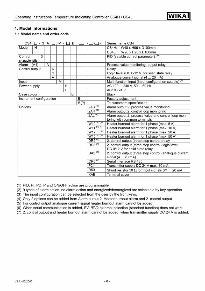
1. Model informations 1.1 Model name and order code
CS4 - 3 A / M - B - - -... Series name CS4_ H CS4H: W48 x H96 x D100mm Model L CS4L: W96 x H96 x D100mm
Control characteristic
3 PID (setable control parameter) (1)
Alarm 1 (A1) A Process value monitoring, output relay (2) R Relay S Logic level (DC 0/12 V) for solid state relay
Control output
A Analogue current signal (4 ... 20 mA) Input M Multi-function input (input configuration setable) (3)
H AC 100 ... 240 V, 50 ... 60 Hz Power supply L AC/DC 24 V
Case colour B Black B Factory adjustment Instrument configuration # (?) To customers specification
2AS (4) Alarm output 2: process value monitoring 2AR (4) Alarm output 2: control loop monitoring 2AL (4) Alarm output 2: process value and control loop moni-
toring with common terminals W10 (4) (5) Heater burnout alarm for 1 phase (max. 5 A) W11 (4) (5) Heater burnout alarm for 1 phase (max. 10 A) W12 (4) (5) Heater burnout alarm for 1 phase (max. 20 A) W15 (4) (5) Heater burnout alarm for 1 phase (max. 50 A) DR2 (4) 2. control output (three step control) relay DS2 (4) 2. control output (three step control) logic level
DC 0/12 V for solid state relay DA2 (4) 2. control output (three step control) analogue current
signal (4 ... 20 mA) CR5 (6) Serial interface RS 485 P24 (7) Transmitter supply DC 24 V max. 30 mA R50 Shunt resistor 50 Ω for input signals 0/4 ... 20 mA
Options
KAB Terminal cover
(1) PID, PI, PD, P and ON/OFF action are programmable. (2) 9 types of alarm action, no alarm action and energized/deenergized are selectable by key operation. (3) The input configuration can be selected from the user by the front keys. (4) Only 2 options can be added from Alarm output 2, Heater burnout alarm and 2. control output. (5) For control output analogue current signal heater burnout alarm cannot be added. (6) When serial communication is added, SV1/SV2 external selection (standard function) does not work. (7) 2. control output and heater burnout alarm cannot be added, when transmitter supply DC 24 V is added.
Operating Instructions Temperature Indicating Controller CS4H / CS4L
V1.1 • 05/2006 - 7 -
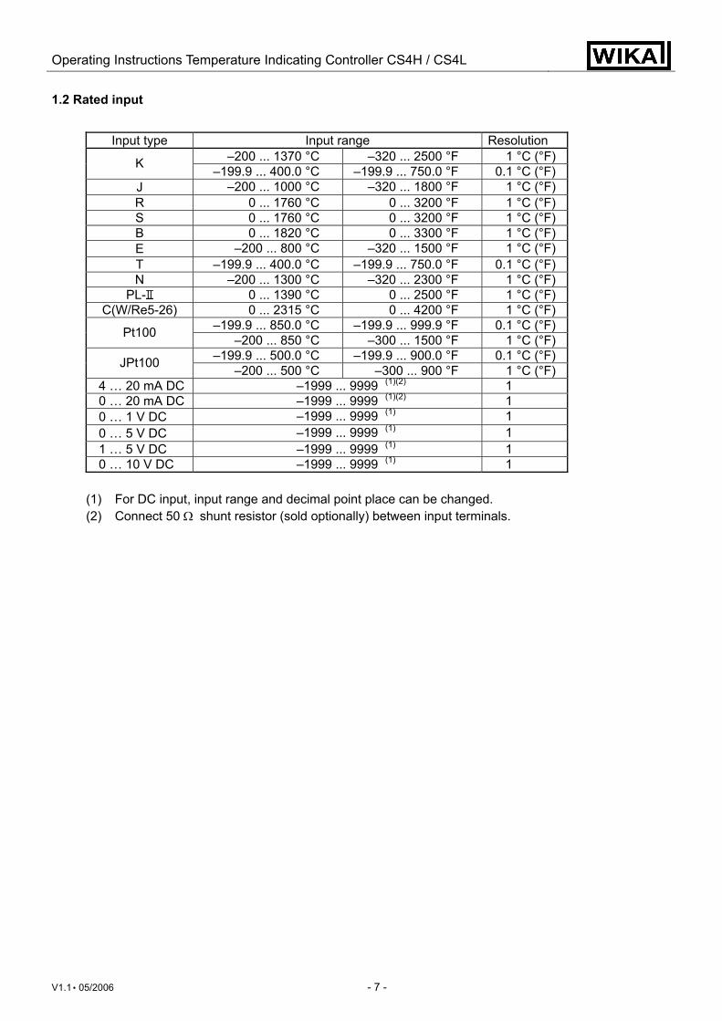
1.2 Rated input
Input type Input range Resolution –200 ... 1370 °C –320 ... 2500 °F 1 °C (°F) K –199.9 ... 400.0 °C –199.9 ... 750.0 °F 0.1 °C (°F)
J –200 ... 1000 °C –320 ... 1800 °F 1 °C (°F) R 0 ... 1760 °C 0 ... 3200 °F 1 °C (°F) S 0 ... 1760 °C 0 ... 3200 °F 1 °C (°F) B 0 ... 1820 °C 0 ... 3300 °F 1 °C (°F) E –200 ... 800 °C –320 ... 1500 °F 1 °C (°F) T –199.9 ... 400.0 °C –199.9 ... 750.0 °F 0.1 °C (°F) N –200 ... 1300 °C –320 ... 2300 °F 1 °C (°F)
PL- 0 ... 1390 °C 0 ... 2500 °F 1 °C (°F) C(W/Re5-26) 0 ... 2315 °C 0 ... 4200 °F 1 °C (°F)
–199.9 ... 850.0 °C –199.9 ... 999.9 °F 0.1 °C (°F) Pt100 –200 ... 850 °C –300 ... 1500 °F 1 °C (°F) –199.9 ... 500.0 °C –199.9 ... 900.0 °F 0.1 °C (°F) JPt100 –200 ... 500 °C –300 ... 900 °F 1 °C (°F)
4 … 20 mA DC –1999 ... 9999 (1)(2) 1 0 … 20 mA DC –1999 ... 9999 (1)(2) 1 0 … 1 V DC –1999 ... 9999 (1) 1 0 … 5 V DC –1999 ... 9999 (1) 1 1 … 5 V DC –1999 ... 9999 (1) 1 0 … 10 V DC –1999 ... 9999 (1) 1
(1) For DC input, input range and decimal point place can be changed. (2) Connect 50 Ω shunt resistor (sold optionally) between input terminals.
Operating Instructions Temperature Indicating Controller CS4H / CS4L
V1.1 • 05/2006 - 8 -
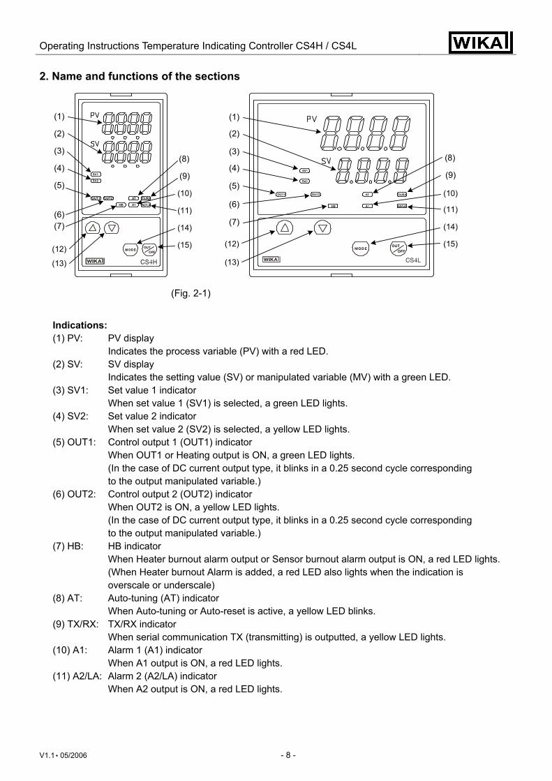
2. Name and functions of the sections
(Fig. 2-1)
Indications: (1) PV: PV display Indicates the process variable (PV) with a red LED. (2) SV: SV display Indicates the setting value (SV) or manipulated variable (MV) with a green LED. (3) SV1: Set value 1 indicator When set value 1 (SV1) is selected, a green LED lights. (4) SV2: Set value 2 indicator When set value 2 (SV2) is selected, a yellow LED lights. (5) OUT1: Control output 1 (OUT1) indicator When OUT1 or Heating output is ON, a green LED lights. (In the case of DC current output type, it blinks in a 0.25 second cycle corresponding to the output manipulated variable.) (6) OUT2: Control output 2 (OUT2) indicator When OUT2 is ON, a yellow LED lights. (In the case of DC current output type, it blinks in a 0.25 second cycle corresponding to the output manipulated variable.) (7) HB: HB indicator When Heater burnout alarm output or Sensor burnout alarm output is ON, a red LED lights. (When Heater burnout Alarm is added, a red LED also lights when the indication is overscale or underscale) (8) AT: Auto-tuning (AT) indicator When Auto-tuning or Auto-reset is active, a yellow LED blinks. (9) TX/RX: TX/RX indicator When serial communication TX (transmitting) is outputted, a yellow LED lights. (10) A1: Alarm 1 (A1) indicator When A1 output is ON, a red LED lights. (11) A2/LA: Alarm 2 (A2/LA) indicator When A2 output is ON, a red LED lights.
(1)
(2)
(3)
(4)
(6)
(7)
(5)
(12)
(9)
(8)
(10)
(15)
(11)
(13)
(14)
(12)
(13)
(1)
(2)
(3)
(4)
(6)(7)
(5)(9)
(8)
(10)
(15)
(11)
(14)
Operating Instructions Temperature Indicating Controller CS4H / CS4L
V1.1 • 05/2006 - 9 -
Keys: (12) ▲: Increase key Increases numeric value of the setting value. (13) ▼: Decrease key Decreases numeric value of the setting value. (14) MODE: Mode key Switches the setting mode and registers the setting value and selected value. (Setting value and selected value are registered by pressing the mode key.) (15) OUT/OFF: OUT/OFF key
• When OUT/OFF function is selected in the OUT/OFF key function selection, control output can be turned on or off. By pressing OUT/OFF key for approx. 1 second from any mode, control output OFF function works. Once the control output OFF function is enabled, the function cannot be released even if the power to the instrument is turned OFF and ON again. Control output OFF function keeps working. To cancel the function, press the OUT/OFF key again for approx. 1 second.
• When Auto/Manual control function is selected in the OUT/OFF key function selection, automatic control starts when the power to the controller is turned on. If the OUT/OFF key is pressed again in this status, manual control starts. If the OUT/OFF key is pressed again during manual control, the control reverts to automatic one. However, Auto/Manual function can be switched only in the PV/SV display mode.
Notice When setting the specifications and functions of this controller, connect the terminals 2 and 3 for power source first, then set them referring to “5. Setup” before performing “3. Mounting to control panel” and “4. Wiring connection”.
Operating Instructions Temperature Indicating Controller CS4H / CS4L
V1.1 • 05/2006 - 10 -
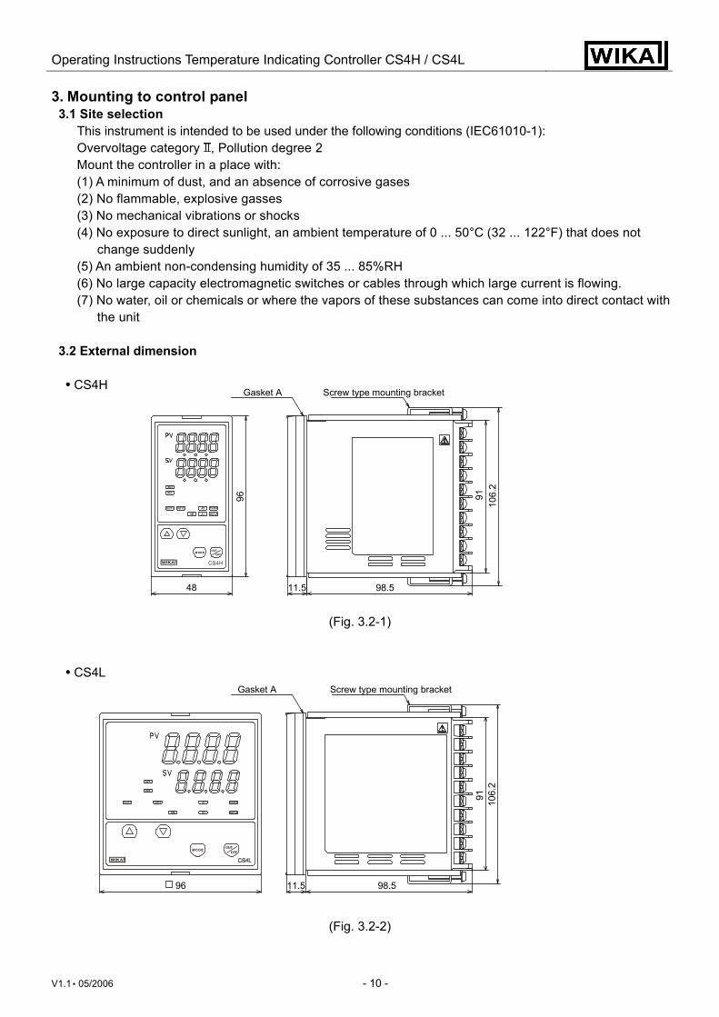
3. Mounting to control panel 3.1 Site selection
This instrument is intended to be used under the following conditions (IEC61010-1): Overvoltage category , Pollution degree 2 Mount the controller in a place with: (1) A minimum of dust, and an absence of corrosive gases (2) No flammable, explosive gasses (3) No mechanical vibrations or shocks (4) No exposure to direct sunlight, an ambient temperature of 0 ... 50°C (32 ... 122°F) that does not
change suddenly (5) An ambient non-condensing humidity of 35 ... 85%RH (6) No large capacity electromagnetic switches or cables through which large current is flowing. (7) No water, oil or chemicals or where the vapors of these substances can come into direct contact with
the unit 3.2 External dimension • CS4H
(Fig. 3.2-1) • CS4L
(Fig. 3.2-2)
96 11.5 98.5
91 106.
2
Gasket A Screw type mounting bracket
48
96
11.5 98.5
9110
6.2
Gasket A Screw type mounting bracket
Operating Instructions Temperature Indicating Controller CS4H / CS4L
V1.1 • 05/2006 - 11 -
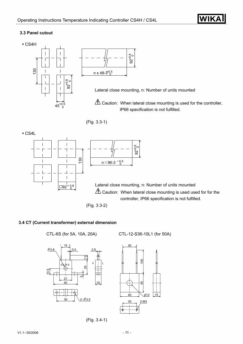
3.3 Panel cutout • CS4H
Lateral close mounting, n: Number of units mounted
Caution: When lateral close mounting is used for the controller, IP66 specification is not fulfilled.
(Fig. 3.3-1)
• CS4L
Lateral close mounting, n: Number of units mounted
Caution: When lateral close mounting is used used for for the controller, IP66 specification is not fulfilled.
(Fig. 3.3-2) 3.4 CT (Current transformer) external dimension CTL-6S (for 5A, 10A, 20A) CTL-12-S36-10L1 (for 50A)
(Fig. 3.4-1)
130
92+0
.8 0
45+0.50
n x 48-3+0.50
92+0
.8 0
150.5
7.5
2.8
10
253
4021
30 2- 3.5
10.5
5.830
100
40
1540
30
12
2-M3
92+ 0.80
130
92+0
.8 0
n×96-3 +0.50
Operating Instructions Temperature Indicating Controller CS4H / CS4L
V1.1 • 05/2006 - 12 -
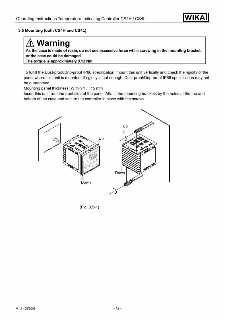
3.5 Mounting (both CS4H and CS4L)
Warning As the case is made of resin, do not use excessive force while screwing in the mounting bracket, or the case could be damaged. The torque is approximately 0.12 Nm.
To fulfill the Dust-proof/Drip-proof IP66 specification, mount this unit vertically and check the rigidity of the panel where this unit is mounted. If rigidity is not enough, Dust-proof/Drip-proof IP66 specification may not be guaranteed. Mounting panel thickness: Within 1 ... 15 mm Insert this unit from the front side of the panel. Attach the mounting brackets by the holes at the top and bottom of the case and secure the controller in place with the screws.
(Fig. 3.5-1)
Up
Down
Up
Down
Operating Instructions Temperature Indicating Controller CS4H / CS4L
V1.1 • 05/2006 - 13 -
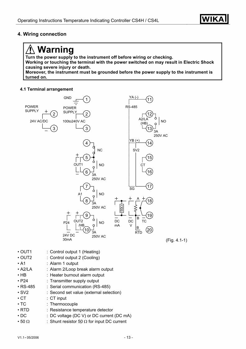
4. Wiring connection
Warning Turn the power supply to the instrument off before wiring or checking. Working or touching the terminal with the power switched on may result in Electric Shock causing severe injury or death. Moreover, the instrument must be grounded before the power supply to the instrument is turned on.
4.1 Terminal arrangement (Fig. 4.1-1) • OUT1 : Control output 1 (Heating) • OUT2 : Control output 2 (Cooling) • A1 : Alarm 1 output • A2/LA : Alarm 2/Loop break alarm output • HB : Heater burnout alarm output • P24 : Transmitter supply output • RS-485 : Serial communication (RS-485) • SV2 : Second set value (external selection) • CT : CT input • TC : Thermocouple • RTD : Resistance temperature detector • DC : DC voltage (DC V) or DC current (DC mA) • 50 Ω : Shunt resistor 50 Ω for input DC current
POWERSUPPLY
POWERSUPPLY
24V AC/DC 100to240V AC
GND
NC
NOOUT1
3A250V AC
NO
3A250V AC
A1
NO
3A250V AC24V DC
30mA
P24 OUT2 /HB
RS-485
NO
3A250V AC
A2/LA (HB)
YA (-)
YB (+)
SV2
CT
SG
DCV
TC
RTDB
B
A
1
2
3
2
3
4
5
6
7
8
9
10
11
12
13
14
15
16
17
18
19
20
DCmA
50Ω
Operating Instructions Temperature Indicating Controller CS4H / CS4L
V1.1 • 05/2006 - 14 -
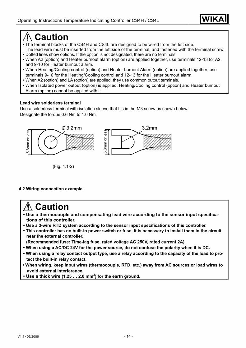
Caution • The terminal blocks of the CS4H and CS4L are designed to be wired from the left side.
The lead wire must be inserted from the left side of the terminal, and fastened with the terminal screw. • Dotted lines show options. If the option is not designated, there are no terminals. • When A2 (option) and Heater burnout alarm (option) are applied together, use terminals 12-13 for A2,
and 9-10 for Heater burnout alarm. • When Heating/Cooling control (option) and Heater burnout Alarm (option) are applied together, use
terminals 9-10 for the Heating/Cooling control and 12-13 for the Heater burnout alarm. • When A2 (option) and LA (option) are applied, they use common output terminals. • When Isolated power output (option) is applied, Heating/Cooling control (option) and Heater burnout
Alarm (option) cannot be applied with it. Lead wire solderless terminal
Use a solderless terminal with isolation sleeve that fits in the M3 screw as shown below. Designate the torque 0.6 Nm to 1.0 Nm.
(Fig. 4.1-2)
4.2 Wiring connection example
Caution • Use a thermocouple and compensating lead wire according to the sensor input specifica-
tions of this controller. • Use a 3-wire RTD system according to the sensor input specifications of this controller. • This controller has no built-in power switch or fuse. It is necessary to install them in the circuit
near the external controller. (Recommended fuse: Time-lag fuse, rated voltage AC 250V, rated current 2A)
• When using a AC/DC 24V for the power source, do not confuse the polarity when it is DC. • When using a relay contact output type, use a relay according to the capacity of the load to pro-
tect the built-in relay contact. • When wiring, keep input wires (thermocouple, RTD, etc.) away from AC sources or load wires to
avoid external interference. • Use a thick wire (1.25 … 2.0 mm2) for the earth ground.
5.8m
m o
r les
s 3.2mm3.2mm
5.8m
m o
r les
s
Operating Instructions Temperature Indicating Controller CS4H / CS4L
V1.1 • 05/2006 - 15 -
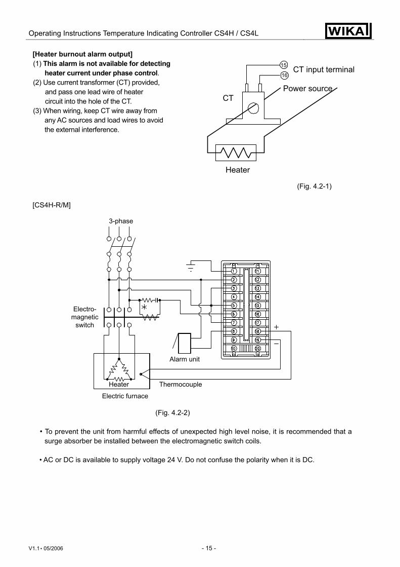
[Heater burnout alarm output] (1) This alarm is not available for detecting
heater current under phase control. (2) Use current transformer (CT) provided,
and pass one lead wire of heater circuit into the hole of the CT.
(3) When wiring, keep CT wire away from any AC sources and load wires to avoid the external interference.
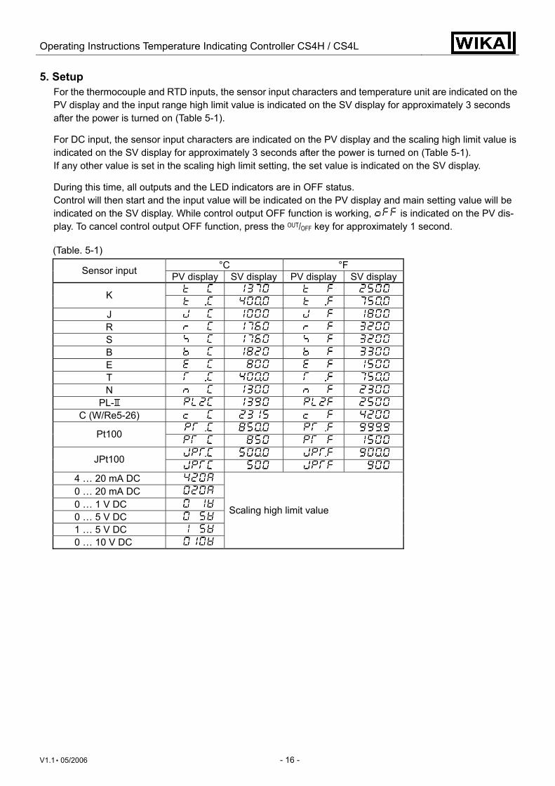
(Fig. 4.2-1) [CS4H-R/M]
(Fig. 4.2-2)
• To prevent the unit from harmful effects of unexpected high level noise, it is recommended that a surge absorber be installed between the electromagnetic switch coils.
• AC or DC is available to supply voltage 24 V. Do not confuse the polarity when it is DC.
3-phase
Electro-magnetic
switch
Heater
Electric furnace
Alarm unit
Thermocouple
CT input terminal
Power sourceCT
Heater
15
16
Operating Instructions Temperature Indicating Controller CS4H / CS4L
V1.1 • 05/2006 - 16 -
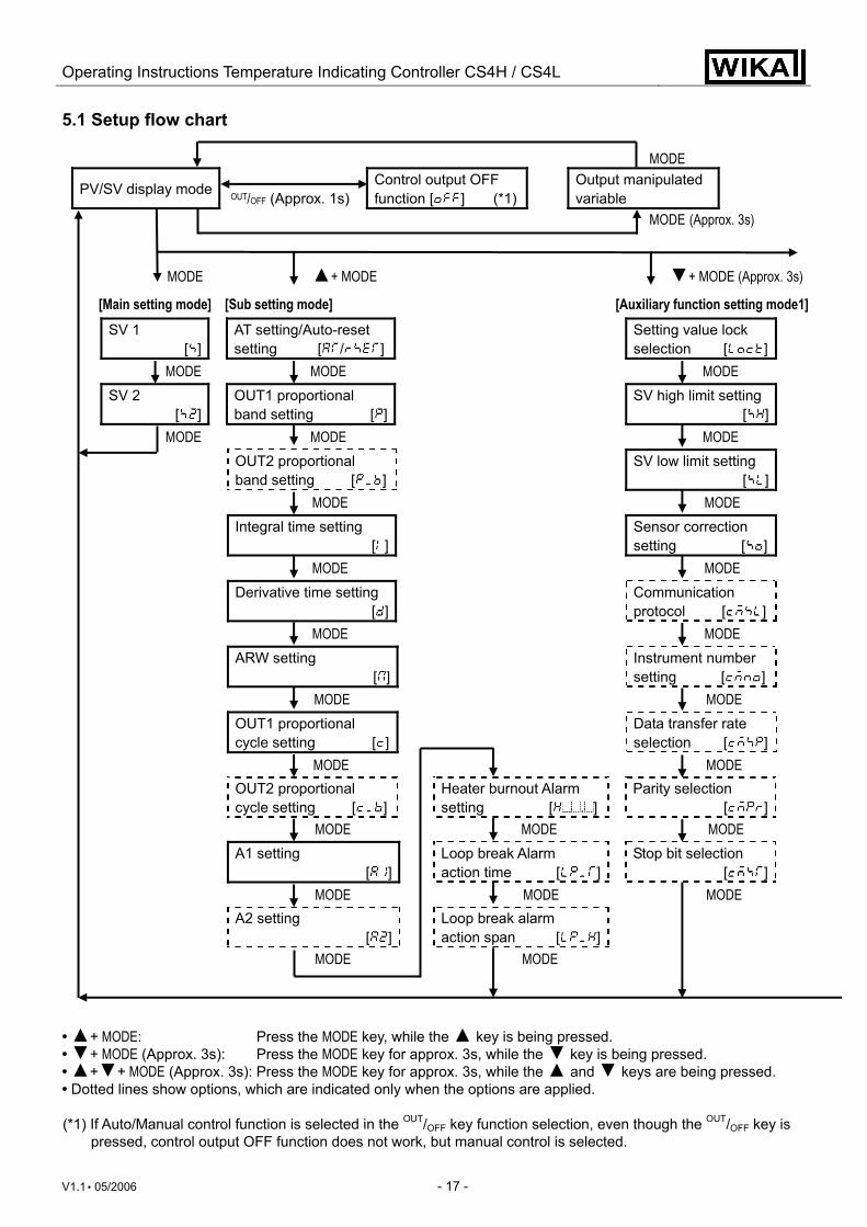
5. Setup For the thermocouple and RTD inputs, the sensor input characters and temperature unit are indicated on the PV display and the input range high limit value is indicated on the SV display for approximately 3 seconds after the power is turned on (Table 5-1).
For DC input, the sensor input characters are indicated on the PV display and the scaling high limit value is indicated on the SV display for approximately 3 seconds after the power is turned on (Table 5-1). If any other value is set in the scaling high limit setting, the set value is indicated on the SV display.
During this time, all outputs and the LED indicators are in OFF status. Control will then start and the input value will be indicated on the PV display and main setting value will be indicated on the SV display. While control output OFF function is working, is indicated on the PV dis-play. To cancel control output OFF function, press the OUT/OFF key for approximately 1 second.
(Table. 5-1)
°C °F Sensor input PV display SV display PV display SV display K
J R S B E T N
PL- C (W/Re5-26)
Pt100
JPt100
4 … 20 mA DC 0 … 20 mA DC 0 … 1 V DC 0 … 5 V DC 1 … 5 V DC 0 … 10 V DC
Scaling high limit value
Operating Instructions Temperature Indicating Controller CS4H / CS4L
V1.1 • 05/2006 - 17 -
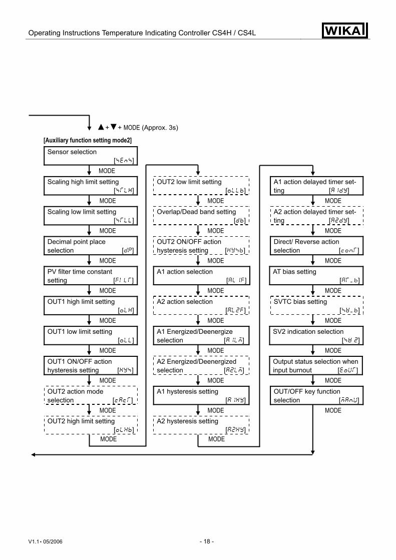
5.1 Setup flow chart MODE
PV/SV display mode OUT/OFF (Approx. 1s)
Control output OFF function [ ] (*1)
Output manipulated variable
MODE (Approx. 3s) MODE ▲+ MODE ▼+ MODE (Approx. 3s)
[Main setting mode] [Sub setting mode] [Auxiliary function setting mode1] SV 1
[ ] AT setting/Auto-reset
setting [ / ] Setting value lock
selection [ ] MODE MODE MODE
SV 2 [ ]
OUT1 proportional band setting [ ]
SV high limit setting [ ]
MODE MODE MODE OUT2 proportional band setting [ ]
SV low limit setting [ ]
MODE MODE Integral time setting
[ ] Sensor correction
setting [ ] MODE MODE
Derivative time setting [ ]
Communication protocol [ ]
MODE MODE ARW setting
[ ] Instrument number
setting [ ] MODE MODE
OUT1 proportional cycle setting [ ]
Data transfer rate selection [ ]
MODE MODE OUT2 proportional cycle setting [ ]
Heater burnout Alarm setting [ . ]
Parity selection [ ]
MODE MODE MODE A1 setting
[ ] Loop break Alarm
action time [ ] Stop bit selection
[ ] MODE MODE MODE
A2 setting [ ]
Loop break alarm action span [ ]
MODE MODE • ▲+ MODE: Press the MODE key, while the ▲ key is being pressed. • ▼+ MODE (Approx. 3s): Press the MODE key for approx. 3s, while the ▼ key is being pressed. • ▲+▼+ MODE (Approx. 3s): Press the MODE key for approx. 3s, while the ▲ and ▼ keys are being pressed. • Dotted lines show options, which are indicated only when the options are applied. (*1) If Auto/Manual control function is selected in the OUT/OFF key function selection, even though the OUT/OFF key is
pressed, control output OFF function does not work, but manual control is selected.
Operating Instructions Temperature Indicating Controller CS4H / CS4L
V1.1 • 05/2006 - 18 -
▲+▼+ MODE (Approx. 3s)
[Auxiliary function setting mode2] Sensor selection
[ ]
MODE Scaling high limit setting
[ ] OUT2 low limit setting
[ ] A1 action delayed timer set-
ting [ ] MODE MODE MODE
Scaling low limit setting [ ]
Overlap/Dead band setting [ ]
A2 action delayed timer set-ting [ ]
MODE MODE MODE Decimal point place selection [ ]
OUT2 ON/OFF action hysteresis setting [ ]
Direct/ Reverse action selection [ ]
MODE MODE MODE PV filter time constant setting [ ]
A1 action selection [ ]
AT bias setting [ ]
MODE MODE MODE OUT1 high limit setting
[ ] A2 action selection
[ ] SVTC bias setting
[ ] MODE MODE MODE
OUT1 low limit setting [ ]
A1 Energized/Deenergize selection [ ]
SV2 indication selection [ ]
MODE MODE MODE OUT1 ON/OFF action hysteresis setting [ ]
A2 Energized/Deenergized selection [ ]
Output status selection wheninput burnout [ ]
MODE MODE MODE OUT2 action mode selection [ ]
A1 hysteresis setting [ ]
OUT/OFF key function selection [ ]
MODE MODE MODE OUT2 high limit setting
[ ] A2 hysteresis setting
[ ] MODE MODE
Operating Instructions Temperature Indicating Controller CS4H / CS4L
V1.1 • 05/2006 - 19 -
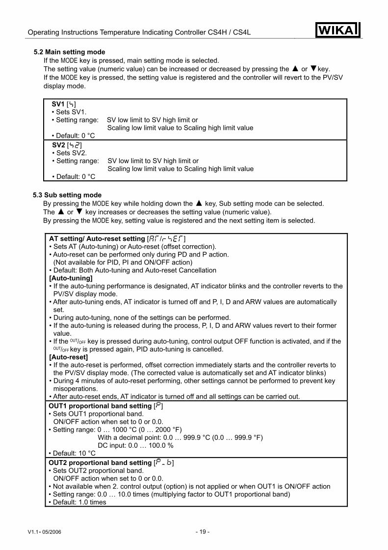
5.2 Main setting mode If the MODE key is pressed, main setting mode is selected. The setting value (numeric value) can be increased or decreased by pressing the ▲ or ▼key. If the MODE key is pressed, the setting value is registered and the controller will revert to the PV/SV display mode.
SV1 [ ] • Sets SV1. • Setting range: SV low limit to SV high limit or Scaling low limit value to Scaling high limit value • Default: 0 °C SV2 [ ] • Sets SV2. • Setting range: SV low limit to SV high limit or Scaling low limit value to Scaling high limit value • Default: 0 °C
5.3 Sub setting mode
By pressing the MODE key while holding down the ▲ key, Sub setting mode can be selected. The ▲ or ▼ key increases or decreases the setting value (numeric value). By pressing the MODE key, setting value is registered and the next setting item is selected.
AT setting/ Auto-reset setting [ / ] • Sets AT (Auto-tuning) or Auto-reset (offset correction). • Auto-reset can be performed only during PD and P action.
(Not available for PID, PI and ON/OFF action) • Default: Both Auto-tuning and Auto-reset Cancellation [Auto-tuning] • If the auto-tuning performance is designated, AT indicator blinks and the controller reverts to the
PV/SV display mode. • After auto-tuning ends, AT indicator is turned off and P, I, D and ARW values are automatically
set. • During auto-tuning, none of the settings can be performed. • If the auto-tuning is released during the process, P, I, D and ARW values revert to their former
value. • If the OUT/OFF key is pressed during auto-tuning, control output OFF function is activated, and if the
OUT/OFF key is pressed again, PID auto-tuning is cancelled. [Auto-reset] • If the auto-reset is performed, offset correction immediately starts and the controller reverts to
the PV/SV display mode. (The corrected value is automatically set and AT indicator blinks) • During 4 minutes of auto-reset performing, other settings cannot be performed to prevent key
misoperations. • After auto-reset ends, AT indicator is turned off and all settings can be carried out. OUT1 proportional band setting [ ] • Sets OUT1 proportional band.
ON/OFF action when set to 0 or 0.0. • Setting range: 0 … 1000 °C (0 … 2000 °F)
With a decimal point: 0.0 … 999.9 °C (0.0 … 999.9 °F) DC input: 0.0 … 100.0 %
• Default: 10 °C OUT2 proportional band setting [ ] • Sets OUT2 proportional band.
ON/OFF action when set to 0 or 0.0. • Not available when 2. control output (option) is not applied or when OUT1 is ON/OFF action • Setting range: 0.0 … 10.0 times (multiplying factor to OUT1 proportional band) • Default: 1.0 times
Operating Instructions Temperature Indicating Controller CS4H / CS4L
V1.1 • 05/2006 - 20 -
Integral time setting [ ] • Sets the integral time.
Setting the value to 0 disables the function. (PD action) • Not available when OUT1 is ON/OFF action • Setting range: 0 … 1000 seconds • Default: 200 seconds Derivative time setting [ ] • Sets the derivative time.
Setting the value to 0 disables the function. (PI action) • Not available when OUT1 is ON/OFF action • Setting range: 0 … 300 seconds • Default: 50 seconds ARW (Anti-reset windup) setting [ ] • Sets the anti-reset windup. • Available only for PID action • Setting range: 0 … 100 % • Default: 50 % OUT1 proportional cycle setting [ ] • Sets OUT1 proportional cycle.
Not available for ON/OFF action and DC current output type • For the relay contact output type, if the proportional cycle time is decreased, the frequency
of the relay action increases and the life of the relay contact is shortened. • Setting range: 1 … 120 seconds • Default: 30 seconds for Relay contact output type,
3 seconds for Non-contact voltage output type OUT2 proportional cycle setting [ ] • Sets OUT2 proportional cycle.
Not available for ON/OFF action and DC current output type • Not available when 2. control output (option) is not added or when OUT2 is ON/OFF action • Setting range: 1 … 120 seconds • Default: 30 seconds for Relay contact output type,
3 seconds for Non-contact voltage output type A1 setting [ ] • Sets the action point of A1 output.
Setting the value to 0 or 0.0 disables the function. (Excluding process high alarm and process low alarm)
• Not available when No alarm action is selected in the A1 action selection • Setting range: Refer to (Table 5.3-1). • Default: 0 °C A2 setting [ ] • Sets the action point of A2 output.
Setting the value to 0 or 0.0 disables the function. (Excluding process high alarm and process low alarm)
• Not available when option [2AS] or [2AL] is not added or when No alarm action is selected in the A2 action selection
• Setting range and default value are the same as those of A1 setting.
Operating Instructions Temperature Indicating Controller CS4H / CS4L
V1.1 • 05/2006 - 21 -
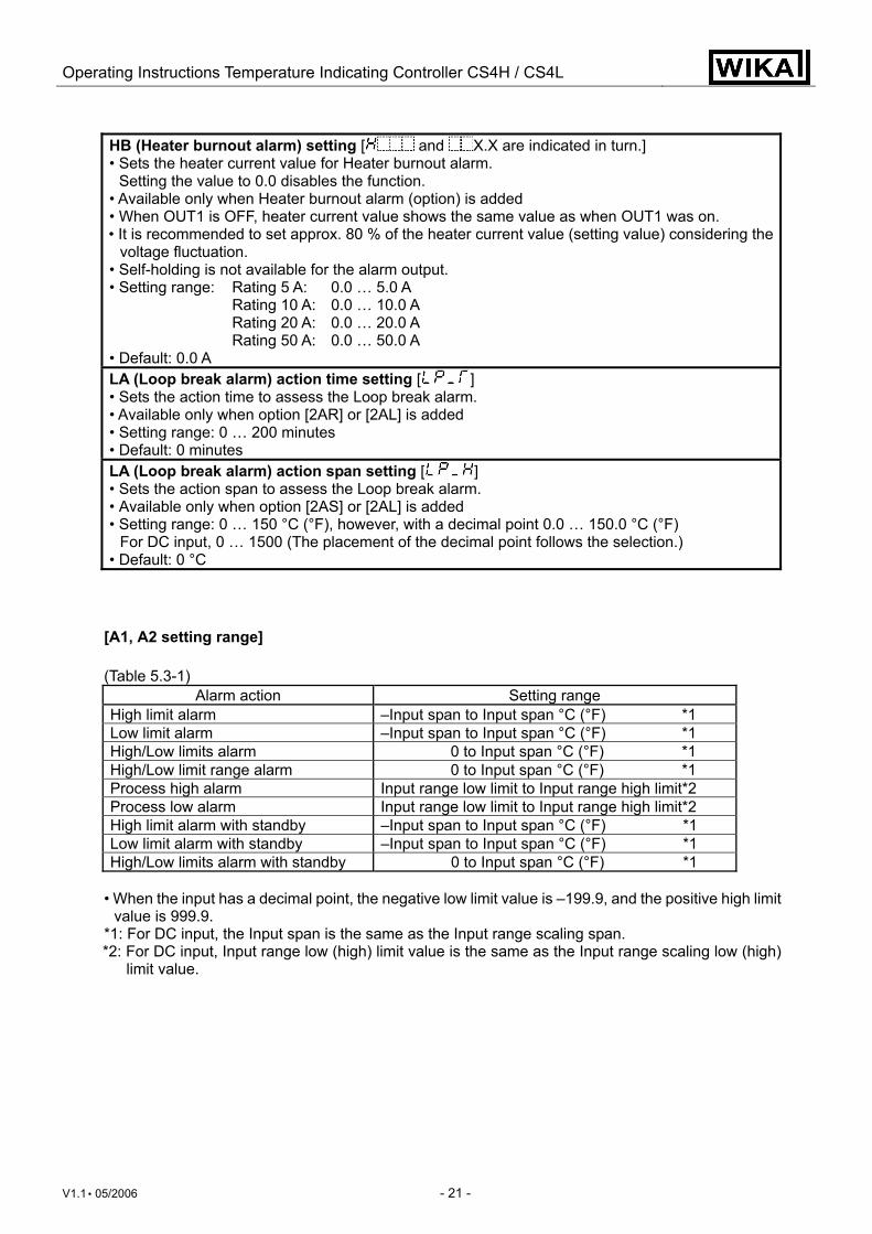
HB (Heater burnout alarm) setting [ and X.X are indicated in turn.] • Sets the heater current value for Heater burnout alarm.
Setting the value to 0.0 disables the function. • Available only when Heater burnout alarm (option) is added • When OUT1 is OFF, heater current value shows the same value as when OUT1 was on. • It is recommended to set approx. 80 % of the heater current value (setting value) considering the
voltage fluctuation. • Self-holding is not available for the alarm output. • Setting range: Rating 5 A: 0.0 … 5.0 A Rating 10 A: 0.0 … 10.0 A Rating 20 A: 0.0 … 20.0 A Rating 50 A: 0.0 … 50.0 A • Default: 0.0 A LA (Loop break alarm) action time setting [ ] • Sets the action time to assess the Loop break alarm. • Available only when option [2AR] or [2AL] is added • Setting range: 0 … 200 minutes • Default: 0 minutes LA (Loop break alarm) action span setting [ ] • Sets the action span to assess the Loop break alarm. • Available only when option [2AS] or [2AL] is added • Setting range: 0 … 150 °C (°F), however, with a decimal point 0.0 … 150.0 °C (°F)
For DC input, 0 … 1500 (The placement of the decimal point follows the selection.) • Default: 0 °C
[A1, A2 setting range] (Table 5.3-1)
Alarm action Setting range High limit alarm –Input span to Input span °C (°F) *1 Low limit alarm –Input span to Input span °C (°F) *1 High/Low limits alarm 0 to Input span °C (°F) *1 High/Low limit range alarm 0 to Input span °C (°F) *1 Process high alarm Input range low limit to Input range high limit*2 Process low alarm Input range low limit to Input range high limit*2 High limit alarm with standby –Input span to Input span °C (°F) *1 Low limit alarm with standby –Input span to Input span °C (°F) *1 High/Low limits alarm with standby 0 to Input span °C (°F) *1
• When the input has a decimal point, the negative low limit value is –199.9, and the positive high limit
value is 999.9. *1: For DC input, the Input span is the same as the Input range scaling span. *2: For DC input, Input range low (high) limit value is the same as the Input range scaling low (high)
limit value.
Operating Instructions Temperature Indicating Controller CS4H / CS4L
V1.1 • 05/2006 - 22 -
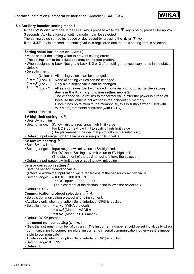
5.4 Auxiliary function setting mode 1 In the PV/SV display mode, if the MODE key is pressed while the ▼ key is being pressed for approx. 3 seconds, Auxiliary function setting mode 1 can be selected. The setting value can be increased or decreased by pressing the ▲ or ▼ key. If the MODE key is pressed, the setting value is registered and the next setting item is selected. Setting value lock selection [ ] • Mode to lock the setting value to prevent setting errors.
The setting item to be locked depends on the designation. • When designating Lock, designate Lock 1, 2 or 3 after setting the necessary items in the status
Unlock. • Selection item:
(Unlock): All setting values can be changed. (Lock 1): None of setting values can be changed. (Lock 2): Only main setting value can be changed. (Lock 3): All setting values can be changed. However, do not change the setting
items in the Auxiliary function setting mode 2. The changed value returns to the former value after the power is turned off because the value is not written in the non-volatile memory. Since it has no relation to the memory life, this is suitable when used with WIKA programmable controller (with SVTC).
• Default: Unlock SV high limit setting [ ] • Sets SV high limit. • Setting range: SV low limit to input range high limit value For DC input, SV low limit to scaling high limit value (The placement of the decimal point follows the selection.) • Default: Input range high limit value or scaling high limit value SV low limit setting [ ] • Sets SV low limit. • Setting range: Input range low limit value to SV high limit For DC input: Scaling low limit value to SV high limit (The placement of the decimal point follows the selection.) • Default: Input range low limit value or scaling low limit value Sensor correction setting [ ] • Sets the sensor correction value.
(Effective within the input rating value regardless of the sensor correction value) • Setting range: –100.0 … 100.0 °C (°F) For DC input: –1000 … 1000 (The placement of the decimal point follows the selection.) • Default: 0.0°C Communication protocol selection [ ] • Selects communication protocol of this instrument. • Available only when the option Serial interface [CR5] is applied • Selection item: (WIKA protocol) (Modbus ASCII mode) (Modbus RTU mode) • Default: WIKA protocol Instrument number setting [ ] • Sets the instrument number of this unit. (The instrument number should be set individually when communicating by connecting plural instruments in serial communication, otherwise it is impos-sible to communicate)
• Available only when the option Serial interface [CR5] is applied • Setting range: 0 … 95 • Default: 0
Operating Instructions Temperature Indicating Controller CS4H / CS4L
V1.1 • 05/2006 - 23 -
Data transfer rate selection [ ] • Selects the data transfer rate of this unit. (The data transfer rate of this unit must be equal to the
rate of the host computer, otherwise it is impossible to communicate) • Available only when the option Serial interface [CR5] is applied • Selection items: (2400 bps)
(4800 bps) (9600 bps) (19200 bps)
• Default: 9600 bps Parity selection [ ] • Selects the parity of this unit. • Not available when the option Serial interface [CR5] is not applied or when WIKA protocol is
selected in the Communication protocol selection • Selection item: (WIKA protocol) (Modbus RTU mode) (Modbus ASCII mode) • Default: WIKA protocol Stop bit selection [ ] • Selects the stop bit of this unit. • Not available when the option Serial interface [CR5] is not applied or when WIKA protocol is
selected in the Communication protocol selection • Selection item: (1)
(2) • Default: 1
Operating Instructions Temperature Indicating Controller CS4H / CS4L
V1.1 • 05/2006 - 24 -
5.5 Auxiliary function setting mode 2
In the PV/SV display mode, if the MODE key is pressed while the ▲ and ▼ keys are being pressed for approx. 3 seconds, Auxiliary function setting mode 2 can be selected. The setting value can be increased or decreased by pressing the ▲ or ▼ key. If the MODE key is pressed, the setting value is registered and the next setting item is selected. If Lock 3 is selected in the Setting value lock selection, release Lock 3 to Unlock, and then change each setting value in the Auxiliary function setting mode 2.
Sensor selection [ ] • An input type from thermocouple (10 types), RTD (2 types), DC current (2 types),
DC voltage (4 types) and the unit °C/°F can be selected. • When changing the input from DC voltage to other inputs, remove the sensor con-
nected to this controller, then change for the input. If the input is changed with the sensor connected, the input circuit may be broken.
• Default: K (–200 … 1370 °C) Input type Input range
–200 … 1370 °C: –320 … 2500 °F: K –199.9 … 400.0 °C: –199.9 … 750.0 °F:
J –200 … 1000 °C: –320 … 1800 °F: R 0 … 1760 °C: 0 … 3200 °F: S 0 … 1760 °C: 0 … 3200 °F: B 0 … 1820 °C: 0 … 3300 °F: E –200 … 800 °C: –320 … 1500 °F: T –199.9 … 400.0 °C: –199.9 … 750.0 °F: N –200 … 1300 °C: –320 … 2300 °F:
PL- 0 … 1390 °C: 0 … 2500 °F: C(W/Re5-26) 0 … 2315 °C: 0 … 4200 °F:
Pt100 –199.9 … 850.0 °C: –199.9 … 999.9 °F: Pt100 –200 … 850 °C: –300 … 1500 °F: JPt100 –199.9 … 500.0 °C: –199.9 … 900.0 °F: JPt100 –200 … 500 °C: –300 … 900 °F:
4 … 20 mA DC –1999 … 9999: 0 … 20 mA DC –1999 … 9999: 0 … 1 V DC –1999 … 9999: 0 … 5 V DC –1999 ... 9999: 1 … 5 V DC –1999 … 9999: 0 … 10 V DC –1999 … 9999:
Scaling high limit setting [ ] • Sets scaling high limit value. • Available only for the DC input • Setting range: Scaling low limit value to Input range high limit value (The placement of the decimal point follows the selection.) • Default: 9999 Scaling low limit setting [ ] • Sets scaling low limit value. • Available only for the DC input • Setting range: Input range low limit value to scaling high limit value (The placement of the decimal point follows the selection.) • Default: –1999
Operating Instructions Temperature Indicating Controller CS4H / CS4L
V1.1 • 05/2006 - 25 -
Decimal point place selection [ ] • Selects the decimal point place. • Available only for DC input • Selection item: (No decimal point)
(1 digit after the decimal point) (2 digits after the decimal point) (3 digits after the decimal point)
• Default: No decimal point PV filter time constant setting [ ] • Sets PV filter time constant.
However, if the setting value is too large, it affects to the control result due to the delay of re-sponse.
• Setting range: 0.0 … 10.0 seconds • Default: 0.0 seconds OUT1 high limit setting [ ] • Sets the high limit value for OUT1.
Not available for ON/OFF action • Setting range: OUT1 low limit value to 100 % (Control output Relay or Logic level DC 0/12 V) OUT1 low limit value to 105 % (Control output Analogue current
signal (4 ... 20 mA)) • Default: 100 % OUT1 low limit setting [ ] • Sets low limit value for OUT1.
Not available for ON/OFF action • Setting range: 0 % to OUT1 high limit value (Control output Relay or Logic level DC 0/12 V) –5 % to OUT1 high limit value (Control output Analogue current
signal (4 ... 20 mA)) • Default: 0 % OUT1 ON/OFF action hysteresis setting [ ] • Sets ON/OFF action hysteresis for OUT1.
Available only for ON/OFF action • Setting range: 0.1 … 100.0 °C (°F) For DC input, 1 … 1000 (the placement of the
decimal point follows the selection) • Default: 1.0 °C OUT2 action mode selection [ ] • Selects OUT2 cooling action from air cooling, oil cooling and water cooling.
Not available when 2. control output (option) is not added or when OUT2 is ON/OFF action • Selection item: (Air cooling, linear characteristic) (Oil cooling, 1.5th power of the linear characteristic) (Water cooling, 2nd power of the linear characteristic) • Default: Air cooling OUT2 high limit setting [ ] • Sets the high limit value for OUT2. • Not available when 2. control output (option) is not added or when OUT2 is ON/OFF action • Setting range: OUT2 low limit value to 100 % (2. control output Relay or Logic level DC 0/12 V)
OUT2 low limit value to 105 % (2. control output Analogue current signal (4 ... 20 mA))
• Default: 100 % OUT2 low limit setting [ ] • Sets the low limit value for OUT2. • Not available when 2. control output (option) is not added or when OUT2 is ON/OFF action • Setting range: 0 % to OUT2 high limit value (2. control output Relay or Logic level DC 0/12 V) –5 % to OUT2 high limit value (2. control output Analogue current
signal (4 ... 20 mA)) • Default: 0 %
Operating Instructions Temperature Indicating Controller CS4H / CS4L
V1.1 • 05/2006 - 26 -
Overlap band/Dead band setting [ ] • Sets Overlap band/Dead band for OUT1 and OUT2.
+ setting value: Dead band – setting value: Overlap band
• Not available for ON/OFF action or when 2. control output (option) is not added • Setting range: –100.0 … 100.0 °C (°F)
for DC input, 1 … 1000 (the placement of the decimal point follows the selection)
• Default: 0.0 °C OUT2 ON/OFF action hysteresis setting [ ] • Sets ON/OFF hysteresis for OUT2. • Available only when 2. control output (option) is added • Setting range: 0.1 … 100.0°C (°F)
For DC input, 1 … 1000 (the placement of the decimal point follows the selection)
• Default: 1.0 °C A1 action selection [ ] • Selects A1 action. • Selection item:
No alarm action : Process high alarm : High limit alarm : Process low alarm : Low limit alarm : High limit alarm with standby : High/Low limits alarm : Low limit alarm with standby : High/Low limit range alarm : High/Low limits alarm with standby :
• Default: No alarm action A2 action selection [ ] • Selects A2 action. • Available only when option [2AS] or [2AL] is added • Selection item, default value are the same as those of A1 action selection. A1 action Energized/Deenergized selection [ ] • Selects A1 action Energized/Deenergized. • Not available when No alarm action is selected in the A1 action selection • Selection item: (Energized)
(Deenergized) • Default: Energized A2 action Energized/Deenergized selection [ ] • Selects Energized or Deenergized for A2 action. • Not available when No alarm action is selected in the A2 action selection or when
option [2AS] or [2AL] is not added • Selection item and default value are the same as those of A1 action Energized/
Deenergized selection. A1 hysteresis setting [ ] • Sets A1 hysteresis. • Not available when No alarm action is selected in the A1 action selection • Setting range: 0.1 … 100.0 °C (°F)
For DC input, 1 … 1000 (the placement of the decimal point follows the selection)
• Default: 1.0 °C A2 hysteresis setting [ ] • Sets A2 hysteresis. • Not available when No alarm action is selected in the A2 action selection or when option [2AS] or
[2AL] is not added • Setting range and default value are the same as those of A1 hysteresis setting.
Operating Instructions Temperature Indicating Controller CS4H / CS4L
V1.1 • 05/2006 - 27 -
A1 action delayed timer setting [ ] • Sets the action delayed timer for A1.
When setting time has passed after the input enters the alarm output range, the alarm is acti-vated.
• Not available if No alarm action is selected in the A1 action selection • Setting range: 0 … 9999 seconds • Default: 0 seconds A2 action delayed timer setting [ ] • Sets the action delayed timer for A2.
When setting time has passed after the input enters the alarm output range, the alarm is acti-vated.
• Not available if No alarm action is selected in the A2 action selection or if option [2AS] or [2AL] is not applied
• Setting range and default value are the same as those of A1 action delayed timer setting. Direct/Reverse action selection [ ] • Selects Reverse (Heating) or Direct (Cooling) action. • Selection item: (Reverse) (Direct) • Default: Reverse (Heating) AT bias setting [ ] • Sets the bias value when PID auto-tuning is performing. • Not available for the DC input • Setting range: 0 … 50 °C (0 … 100 °F)
With a decimal point, 0.0 … 50.0 °C (0.0 … 100.0 °F) • Default: 20 °C SVTC bias setting [ ] • Control desired value adds SVTC bias value to the value received by the SVTC command. • Available only when the serial interface (option) is added • Setting range: Converted value of ±20 % of the rated value or ±20 % of the scaling span (DC
input) (the placement of the decimal point follows the selection.) However, the negative minimum value is –1999, –199.9, –19.99 or –1.999.
• Default: 0 SV2 indication selection [ ] • Selects whether SV2 is indicated or not. • Available only when serial interface (option) is added • Selection item: (Indication) (No indication) • Default: Indication Output status selection when input burnout [ ] • Selects output status when input is burnt out. Available only for control output analogue current signal (4 ... 20 mA) with DC inputs • Selection item: (Output OFF) (Output ON) • Default: Output OFF OUT/OFF key function selection [ ] • Selects the OUT/OFF key function. • Selection item: (OUT/OFF function) (Auto/Manual control function) • Default: OUT/OFF function
Operating Instructions Temperature Indicating Controller CS4H / CS4L
V1.1 • 05/2006 - 28 -
[Sensor correction function]
This corrects the input value from the sensor. When a sensor cannot be set at a location where control is desired, the sensor measuring temperature may deviate from the temperature in the controlled location. When controlling with plural controllers, sometimes the temperatures measured (input value) do not concur with the same setting value due to difference in sensor accuracy or dispersion of load capacities. In such a case, the control can be set at the desired temperature by adjusting the input value of sensors. However, it is effective within the input rating range regardless of the sensor correction value.
[Loop break alarm] The alarm will be activated when the process variable (PV) does not rise as much as the span or greater within the time it takes to assess the loop break alarm after the manipulated variable has reached 100 % or the output high limit value. The alarm will also be activated when the process variable (PV) does not fall as much value as the span or greater within the time it takes to assess loop break alarm after the manipulated variable has reached 0 % or the output low limit value. When the control action is Direct (Cooling), read “fall” for “rise” and vice versa.
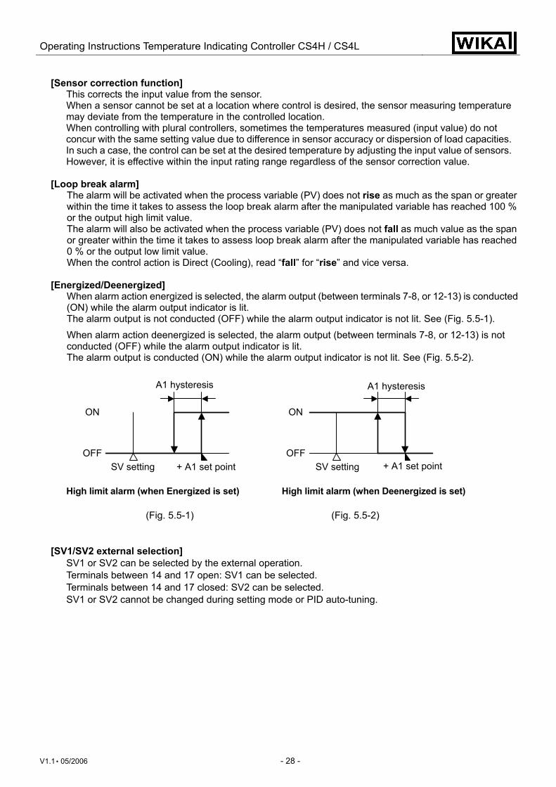
[Energized/Deenergized]
When alarm action energized is selected, the alarm output (between terminals 7-8, or 12-13) is conducted (ON) while the alarm output indicator is lit. The alarm output is not conducted (OFF) while the alarm output indicator is not lit. See (Fig. 5.5-1). When alarm action deenergized is selected, the alarm output (between terminals 7-8, or 12-13) is not conducted (OFF) while the alarm output indicator is lit. The alarm output is conducted (ON) while the alarm output indicator is not lit. See (Fig. 5.5-2). High limit alarm (when Energized is set) High limit alarm (when Deenergized is set)
(Fig. 5.5-1) (Fig. 5.5-2)
[SV1/SV2 external selection] SV1 or SV2 can be selected by the external operation. Terminals between 14 and 17 open: SV1 can be selected. Terminals between 14 and 17 closed: SV2 can be selected. SV1 or SV2 cannot be changed during setting mode or PID auto-tuning.
OFF
ON
A1 hysteresis
SV setting + A1 set pointOFF
ON
SV setting + A1 set point
A1 hysteresis
Operating Instructions Temperature Indicating Controller CS4H / CS4L
V1.1 • 05/2006 - 29 -
5.6 Control output OFF function
Control output OFF function [ ] • A function to pause the control action or turn the control output of the unused instrument of the
plural units OFF even if the power to the instrument is supplied. [ ] is indicated on the PV display while the function is working.
• Pressing the OUT/OFF key for approx. 1 second from any mode turns the control output OFF. Pressing the OUT/OFF key again for approx. 1 second cancels the control output OFF function.
• Once the control output OFF function is enabled, the function cannot be released even if the power to the instrument is turned OFF and ON again. To cancel the function, press the OUT/OFF key again for approx. 1 second.
5.7 Auto/Manual control function
PV/SV display mode (Manual control) • To use manual control function, Auto/Manual control function must be selected in the OUT/OFF key
function selection. First, press the OUT/OFF key. Control can be performed by increasing or decreasing the output manipulated variable (MV) using the ▲ or ▼ key.
• The 1st decimal point from the right on the SV display blinks. • By pressing the OUT/OFF key again, the mode reverts to the PV/SV display (automatic control)
mode. Whenever the power to the controller is turned on, automatic control starts. • If control action is switched from automatic to manual or vice versa, balanceless-bumpless
function works to prevent sudden change of manipulated variable. • If Auto/Manual control function is selected, control output OFF function is disabled.
5.8 Output manipulated variable indication
Output manipulated variable indication • Output manipulated variable is indicated on the SV display by pressing the MODE key for approx.
3 seconds in the PV/SV display mode. While output manipulated variable is being indicated, the 1st decimal point from the right on the SV display blinks at a cycle of every 0.5 second. When the MODE key is pressed again, the mode reverts to the PV/SV display.
Operating Instructions Temperature Indicating Controller CS4H / CS4L
V1.1 • 05/2006 - 30 -
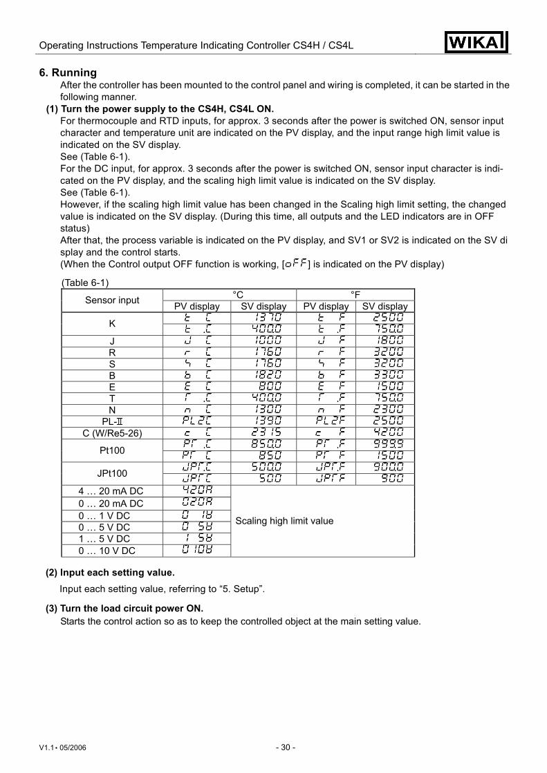
6. Running After the controller has been mounted to the control panel and wiring is completed, it can be started in the following manner.
(1) Turn the power supply to the CS4H, CS4L ON. For thermocouple and RTD inputs, for approx. 3 seconds after the power is switched ON, sensor input character and temperature unit are indicated on the PV display, and the input range high limit value is indicated on the SV display. See (Table 6-1). For the DC input, for approx. 3 seconds after the power is switched ON, sensor input character is indi-cated on the PV display, and the scaling high limit value is indicated on the SV display. See (Table 6-1). However, if the scaling high limit value has been changed in the Scaling high limit setting, the changed value is indicated on the SV display. (During this time, all outputs and the LED indicators are in OFF status) After that, the process variable is indicated on the PV display, and SV1 or SV2 is indicated on the SV display and the control starts. (When the Control output OFF function is working, [ ] is indicated on the PV display)
(Table 6-1) °C °F Sensor input PV display SV display PV display SV display
K J R S B E T N
PL- C (W/Re5-26)
Pt100 JPt100
4 … 20 mA DC 0 … 20 mA DC 0 … 1 V DC 0 … 5 V DC 1 … 5 V DC 0 … 10 V DC
Scaling high limit value
(2) Input each setting value. Input each setting value, referring to “5. Setup”.
(3) Turn the load circuit power ON. Starts the control action so as to keep the controlled object at the main setting value.
Operating Instructions Temperature Indicating Controller CS4H / CS4L
V1.1 • 05/2006 - 31 -
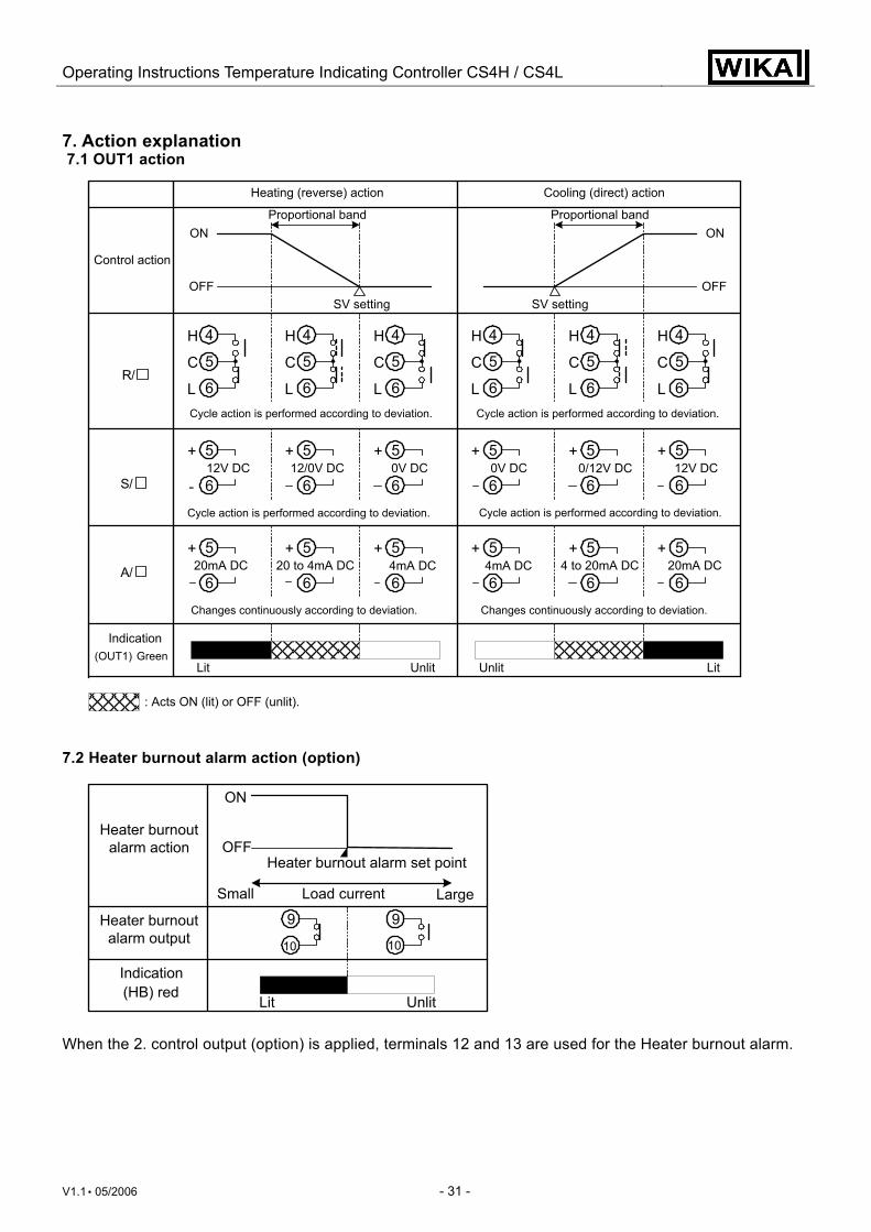
7. Action explanation 7.1 OUT1 action
7.2 Heater burnout alarm action (option)
When the 2. control output (option) is applied, terminals 12 and 13 are used for the Heater burnout alarm.
Small Large
9
10
9
10
Heater burnout alarm set point
Load current
Heater burnoutalarm action
Heater burnoutalarm output
Indication(HB) red
Lit Unlit
ON
OFF
Heating (reverse) action Cooling (direct) action
Proportional band
(OUT1) GreenIndication
Lit
: Acts ON (lit) or OFF (unlit).
Cycle action is performed according to deviation.
Cycle action is performed according to deviation.
Changes continuously according to deviation.
OFF
ON
OFF
ON
5+
6-12V DC
5+
612/0V DC
5+
60V DC
5+
60V DC
5+
612V DC
5+
60/12V DC
5+
620mA DC
5+
6 4mA DC
5+
6 4mA DC
5+
620mA DC
5+
64 to 20mA DC
4
5
6
H
C
L
4
5
6
H
C
L
4
5
6
H
C
L
4
5
6
H
C
L
4
5
6
H
C
L
4
5
6
H
C
L
+
620 to 4mA DC
5
Cycle action is performed according to deviation.
Cycle action is performed according to deviation.
Changes continuously according to deviation.
LitUnlitUnlit
Control action
SV setting
Proportional band
R/
SV setting
S/
A/
Operating Instructions Temperature Indicating Controller CS4H / CS4L
V1.1 • 05/2006 - 32 -
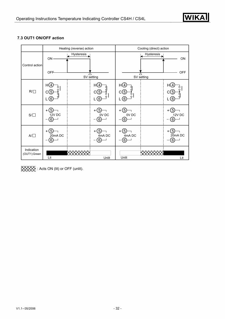
7.3 OUT1 ON/OFF action
Heating (reverse) action
Control action
Cooling (direct) action
Hysteresis
SV setting
(OUT1) GreenIndication
Unlit
Hysteresis
5+
612V DC
5+
60V DC
5+
60V DC
5+
612V DC
5+
620mA DC
5+
64mA DC
5+
64mA DC
5+
620mA DC
4
5
6
H
C
L
4
5
6
H
C
L
4
5
6
H
C
L
4
5
6
H
C
L
OFF
ON
OFF
ON
Lit Unlit Lit
SV setting
R/
S/
A/
: Acts ON (lit) or OFF (unlit).
Operating Instructions Temperature Indicating Controller CS4H / CS4L
V1.1 • 05/2006 - 33 -
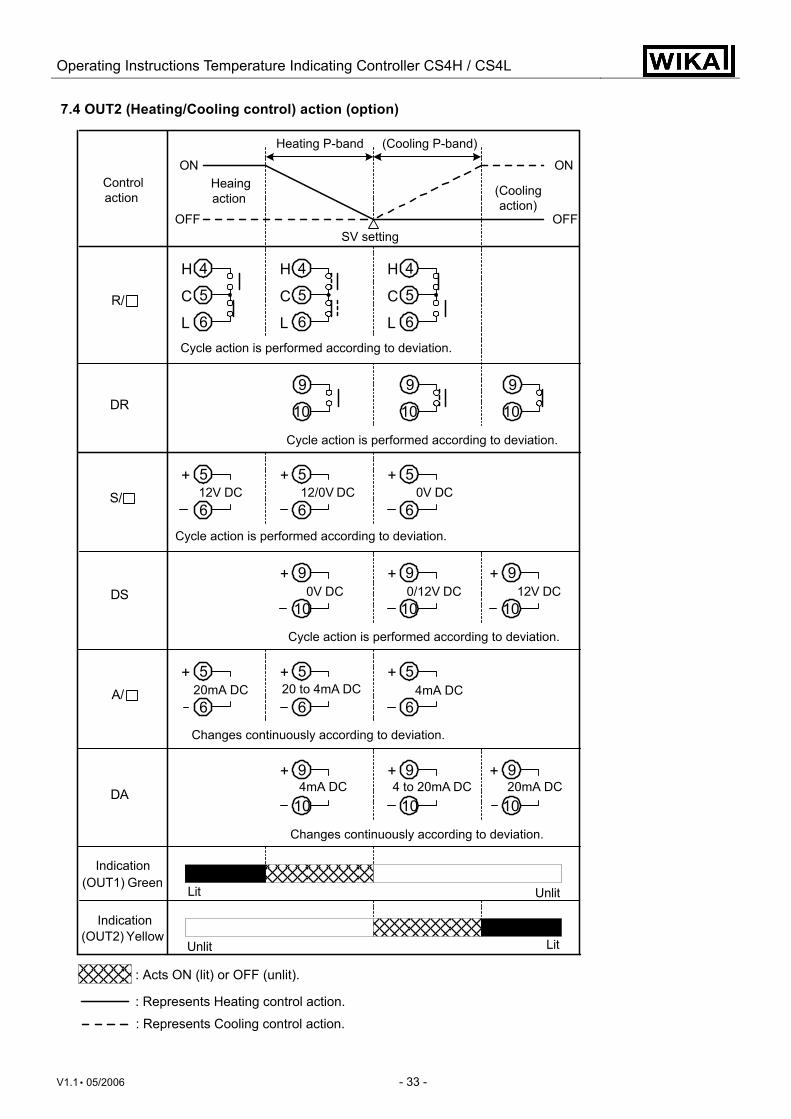
7.4 OUT2 (Heating/Cooling control) action (option)
Controlaction
Heating P-band (Cooling P-band)
OFF
ON
5+
612V DC
5+
612/0V DC
5+
60V DC
5+
6 20mA DC
5+
6 20 to 4mA DC
5+
6 4mA DC
4
5
6
H
C
L
4
5
6
H
C
L
4
5
6
H
C
L
9
10
9
10
9
10
9+
10 0V DC
9+
1012V DC
9+
10 0/12V DC
9+
10 4 to 20mA DC
9+
10 4mA DC
9+
10 20mA DC
(OUT2) Yellow
OFF
ON Heaingaction (Cooling
action)
SV setting
Cycle action is performed according to deviation.
Cycle action is performed according to deviation.
Cycle action is performed according to deviation.
Changes continuously according to deviation.
Cycle action is performed according to deviation.
Changes continuously according to deviation.
Lit Unlit
Unlit Lit
Indication
(OUT1) GreenIndication
R/
S/
A/
DR
DS
DA
: Acts ON (lit) or OFF (unlit).
: Represents Heating control action.
: Represents Cooling control action.
Operating Instructions Temperature Indicating Controller CS4H / CS4L
V1.1 • 05/2006 - 34 -
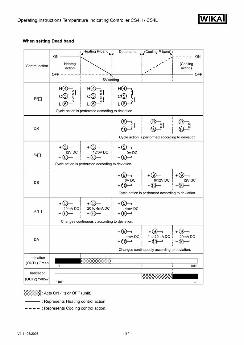
When setting Dead band
(OUT1) Green
OFF
ON
OFF
ON
4
5
6
H
C
L
4
5
6
H
C
L
4
5
6
H
C
L
9
10
9
10
9
10
(OUT2) Yellow
5+
612V DC
5+
6 12/0V DC
5+
6 0V DC
5+
6 20mA DC
5+
6 20 to 4mA DC
5+
6 4mA DC
9+
10 0V DC
9+
1012V DC
9+
10 0/12V DC
9+
104 to 20mA DC
9+
10 4mA DC
9+
1020mA DC
Control action (Coolingaction)
Heatngaction
Heating P-band Dead band (Cooling P-band)
SV setting
Cycle action is performed according to deviation.
Cycle action is performed according to deviation.
Cycle action is performed according to deviation.
Cycle action is performed according to deviation.
Indication
Indication
Lit
Unlit Lit
Unlit
Changes continuously according to deviation.
Changes continuously according to deviation.
R/
S/
A/
DR
DS
DA
: Acts ON (lit) or OFF (unlit).
: Represents Heating control action.
: Represents Cooling control action.
Operating Instructions Temperature Indicating Controller CS4H / CS4L
V1.1 • 05/2006 - 35 -
When setting Overlap band with Relay contact output.
OFF
ON
OFF
ON
4
5
6
H
C
L
4
5
6
H
C
L
4
5
6
H
C
L
9
10
9
10
9
10
(OUT2) Yellow
Control action
SV setting
(OUT1) GreenIndication
Lit
Indication
Heating P-band
Cooling P-band
Overlap band
Heatingaction
(Coolingaction)
Cycle action is performed according to deviation.
Cycle action is performed according to deviation.
Lit
Unlit
Unlit
R/
DR
: Acts ON (lit) or OFF (unlit).
: Represents Heating control action.
: Represents Cooling control action.
Operating Instructions Temperature Indicating Controller CS4H / CS4L
V1.1 • 05/2006 - 36 -
7.5 A1 and A2 actions
: A1 output terminals between 7 and 8 is ON.
: Standby functions.
: A1 output terminals between 7 and 8 is ON or OFF.
: A1 output terminals between 7 and 8 is OFF.
OFF
ON
OFF
ON
OFF
ON
OFF
ON
OFF
ON
OFF
ON
OFF
ON
OFF
ON
Alarm action
High limit alarm Low limit alarm
Setting
A1 hysteresis
Process high alarm Process low alarm
High/Low limits alarm High/Low limit range alarm
Alarm output
+ Alarmset point
Setting Setting
+ side
side
+ side
side
Setting+ Alarmset point
Alarmset point
Alarmset point
Alarmset point
Alarmset point
Alarmset point
Alarmset pointAlarm
set point
Alarm output
Alarm action
Alarm action
Alarm output
Alarm action
High limit alarm with standby Low limit alarm with standby
Alarm output+ side
side
+ side
side
+ Alarmset point
Setting
Alarmset point
Alarmset point
Alarmset point
Setting + Alarmset point
A1 hysteresis
A1 hysteresis A1 hysteresis
A1 hysteresis A1 hysteresis
A1 hysteresisA1 hysteresis
Operating Instructions Temperature Indicating Controller CS4H / CS4L
V1.1 • 05/2006 - 37 -
For A2 output, terminals 12 and 13 are used.
A1 and A2 indicators light up when between the output terminals is ON, and goes out when between them
is OFF.
7.6 SV1/SV2 external selection action
If the serial communication is applied, this function is disabled. 8. Control action explanations
8.1 PID (1) Proportional band (P)
Proportional action is the action which the control output varies in proportion to the deviation between the setting value and the processing temperature. If the proportional band is narrowed, even if the output changes by a slight variation of the processing temperature, better control results can be obtained as the offset decreases. However, if the proportional band is narrowed too much, even slight disturbances may cause variation in the processing temperature, control action changes to ON/OFF action and the so called hunting phenomenon occurs. Therefore, when the processing temperature comes to the balanced position near the setting value and a constant temperature is maintained, the most suitable value is selected by gradually narrowing the proportional band while observing the control results.
(2) Integral time (I) Integral action is used to eliminate offset. When the integral time is shortened, the returning speed to the setting point is accelerated. However, the cycle of oscillation is also accelerated and the control be-comes unstable.
(3) Derivative time (D) Derivative action is used to restore the change in the processing temperature according to the rate of change. It reduces the amplitude of overshoot and undershoot width. If the derivative time is shortened, restoring value becomes small, and if the derivative time is made longer, an excessive returning phenomenon may occur and the control system may be oscillated.
SV1
SV1/SV2externalselection
14
17
14
17
SV2 SV1 SV2
SV1 SV2
LitUnlitUnlitLitIndication
Green
OFF
ON
High/Low limits alarm with standby
SV setting A1 set point
A1 set point
Alarm action
Alarm output
A1 hysteresis
: A1 output terminals between 7 and 8 is ON.
: Standby functions.
: A1 output terminals between 7 and 8 is ON or OFF.
: A1 output terminals between 7 and 8 is OFF.
Operating Instructions Temperature Indicating Controller CS4H / CS4L
V1.1 • 05/2006 - 38 -
8.2 PID auto-tuning of this controller In order to decide each value of P, I, D and ARW automatically, this system forcibly fluctuates the object being controlled.
(1) When the difference between the setting value and processing temperature is large as the temperature rises. Fluctuation is applied at the temperature 20 °C lower than the setting value.
(1) Calculating PID con-stant
(2) PID constant calculated
(3) Controlled by the PID constant set by auto- tuning.
(4) AT bias value
(Fig. 8.2-1)
(2) When the control is stable or when control temperature is within ±20 °C (°F) of setting value. Fluctuation is applied at the setting value.
(1) Calculating PID con-
stant (2) PID constant
calculated (3) Controlled by the PID
constant set by auto-tuning.
(Fig. 8.2.2)
(3) When the control temperature is 20 °C (°F) or higher than the setting value. Fluctuation is applied at the temperature 20 °C (°F) higher than the setting value.
(1) Calculating PID constant
(2) PID constant calculated
(3) Controlled by the PID constant set by auto-tuning.
(4) AT bias value
(Fig. 8.2.3)
Temperature 20 °C (°F) lower than the setting value
Temperature 20 °C (°F) higher than the setting value
(1) (2) (3)
(4)
AT starting point
Settingvalue
Temperature
Time
AT starting point
(1) (2) (3)
Temperature
Settingvalue
Time
AT starting point
(1) (2) (3)
(4)
Temperature
Settingvalue
Time
Operating Instructions Temperature Indicating Controller CS4H / CS4L
V1.1 • 05/2006 - 39 -
8.3 Auto-reset (offset correction) Auto-reset is performed to correct the offset at the point at which PV indication is stabilized within the proportional band during the PD action. Since the corrected value is internally memorized, it is not necessary to perform the auto-reset again as long as the process is the same. However, when the proportional band is set to 0, the corrected value is cleared.
(Fig. 8.3-1)
Temperature
Settingvalue Offset span
Time
Offset is corrected
Auto-reset is performed
Operating Instructions Temperature Indicating Controller CS4H / CS4L
V1.1 • 05/2006 - 40 -
9. Specifications 9.1 Standard specifications
Mounting method : Flush Setting method : Membrane sheet key
Display CS4H PV display : Red LED 4 digits, character size, 11.2 x 5.4 (H x W) mm
SV display : Green LED 4 digits, character size, 11.2 x 5.4 (H x W) mm CS4L PV display : Red LED 4 digits, character size, 18 x 8 (H x W) mm
SV display : Green LED 4 digits, character size, 12.6 x 6(H x W) mm Input
Thermocouple : K, J, R, S, B, E, T, N, PL- , C (W/Re5-26) External resistance, 100 Ω or less, however, for B, 40 Ω or less
RTD : Pt100, JPt100, 3-wire system Allowable input lead wire resistance, 10 Ω or less per wire DC current : 0 … 20 mA DC, 4 … 20 mA DC Input impedance, 50 Ω [50 Ω Shunt resistor (sold optionaly) must be connected between input terminals] Allowable input current 50 mA or less [If 50 Ω Shunt resistor (sold optionaly) is used] DC voltage : 0 … 1 V DC Input impedance, 1 MΩ or greater Allowable input voltage 5 V or less Allowable signal source resistance 2 kΩ or less 0 … 5 V DC, 1 … 5 V DC, 0 … 10 V DC, Input impedance, 100 kΩ or greater Allowable input voltage 15 V or less Allowable signal source resistance 100 Ω or less
Rated input Input type Input range Resolution
–200 ... 1370 °C –320 ... 2500 °F 1 °C (°F) K –199.9 ... 400.0 °C –199.9 ... 750.0 °F 0.1 °C (°F) J –200 ... 1000 °C –320 ... 1800 °F 1 °C (°F) R 0 ... 1760 °C 0 ... 3200 °F 1 °C (°F) S 0 ... 1760 °C 0 ... 3200 °F 1 °C (°F) B 0 ... 1820 °C 0 ... 3300 °F 1 °C (°F) E –200 ... 800 °C –320 ... 1500 °F 1 °C (°F) T –199.9 ... 400.0 °C –199.9 ... 750.0 °F 0.1 °C (°F) N –200 ... 1300 °C –320 ... 2300 °F 1 °C (°F)
PL- 0 ... 1390 °C 0 ... 2500 °F 1 °C (°F) C(W/Re5-26) 0 ... 2315 °C 0 ... 4200 °F 1 °C (°F)
–199.9 ... 850.0 °C –199.9 ... 999.9 °F 0.1 °C (°F) Pt100 –200 ... 850 °C –300 ... 1500 °F 1 °C (°F) –199.9 ... 500.0 °C –199.9 ... 900.0 °F 0.1 °C (°F) JPt100 –200 ... 500 °C –300 ... 900 °F 1 °C (°F)
4 ... 20 mA DC 0 ... 20 mA DC –1999 ... 9999 *1 *2 1
0 ... 1 V DC 0 ... 5 V DC 1 ... 5 V DC 0 ... 10 V DC
–1999 ... 9999 *1 1
*1: For DC input, input range and decimal point place are changeable. *2: 50 Ω Shunt resistor (sold optionally) must be connected between input terminals.
Operating Instructions Temperature Indicating Controller CS4H / CS4L
V1.1 • 05/2006 - 41 -
Accuracy (Setting, indication) Thermocouple : Within ±0.2 % of input range full scale ±1 digit or within ±2 °C (4 °F), whichever is greater However, R, S inputs, 0 … 200 °C (0 … 400 °F): Within ±6 °C (12 °F) B input, 0 … 300 °C (0 … 600 °F): Accuracy is not guaranteed. K, J, E, T, N inputs, less than 0 °C (32 °F): Within ±0.4 % of input range full scale ±1 digit RTD : Within ±0.1 % of input range full scale ±1 digit or within ±1 °C (2 °F), whichever is greater DC Voltage and Current: Within ±0.2 % of input range full scale ±1digit
Input sampling period : 0.25 seconds Control output (OUT1)
Relay contact : Control capacity, 3 A, 250 V AC (resistive load) 1 A, 250 V AC (inductive load cos ø = 0.4) Electrical life 100,000 times Logic level DC 0/12 V for solid state relay: 12+ 2
- 0 V DC maximum 40 mA (short circuit protected) Analogue current signal : 4 … 20 mA DC Load resistance, maximum 550 Ω
A1 output When A1 action is set as energized, the alarm action point is set by ±deviation to the main setting (except Process alarm). When the input exceeds the range, the output turns ON or OFF (in the case of High/Low limit range alarm). When the alarm action is set as deenergized, the output acts conversely.
Setting accuracy : The same as the Indicating accuracy Action : ON/OFF action Hysteresis : Thermocouple and RTD inputs, 0.1 … 100.0 °C (°F) DC current and DC voltage inputs, 1 … 1000 (The placement of the decimal point follows the selection) Output : Relay contact 1a Control capacity 3 A, 250 V AC (resistive load) Electrical life 100,000 times
Control action • PID action (with auto-tuning function) • PI action: When derivative time is set to 0 • PD action (with auto-reset function): When integral time is set to 0 • P action (with auto-reset function): When integral and derivative times are set to 0 • ON/OFF action OUT1 proportional band (P): Thermocouple, 0 ... 1000°C (0 ... 2000°F) RTD, 0.0 ... 999.9°C (0.0 ... 999.9°F) DC current and voltage, 0.0 ... 100.0% (ON/OFF action when set to 0°C (°F), 0.0°C (°F) or 0.0%) Integral time (I) : 0 ... 1000 s (off when set to 0)
Derivative time (D) : 0 ... 300 s (off when set to 0) OUT1 proportional cycle : 1 ... 120 s (Not available for control output analogue current signal)
ARW : 0 ... 100 % OUT1 hysteresis : Thermocouple and RTD inputs, 0.1 ... 100.0 °C (°F) DC current and voltage inputs, 1 ... 1000 (The placement of the decimal point follows the selection)
SV1/SV2 external selection: SV1 and SV2 can be selected by external contact. Contact open between terminals 14 and 17 : SV1 Contact closed between terminals 14 and 17 : SV2 Contact current: 6mA
Operating Instructions Temperature Indicating Controller CS4H / CS4L
V1.1 • 05/2006 - 42 -
Supply voltage : 100 ... 240 V AC 50/60Hz or 24 V AC/DC 50/60Hz
Allowable voltage fluctuation range 100 ... 240 V AC : 85 ... 264 V AC 24 V AC/DC : 20 ... 28V AC/DC
Ambient temperature : 0 ... 50 °C (32 ... 122 °F) Ambient humidity : 35 ... 85 %RH (no condensation) Power consumption : Approx. 8 VA or 8 W Circuit Isolation configuration
• When OUT1 is Logic level DC 0/12 V or Analogue current signal (4 ... 20 mA) and OUT2 is Logic level
DC 0/12 V or Analogue current signal (4 ... 20 mA), between A to B is non-isolated. • When OUT1 is Logic level DC 0/12 V or Analogue current signal (4 ... 20 mA), between A to C and A
to D are non-isolated. When OUT2 is Logic level DC 0/12 V or Analogue current signal (4 ... 20 mA), between B to C and B to D are non-isolated.
Isolation resistance 10 MΩ or greater at 500 V DC for other combinations except the above mentioned
Dielectric strength Between input terminal and ground terminal, 1.5 kV AC for 1 minute Between input terminal and power terminal, 1.5 kV AC for 1 minute Between output terminal and ground terminal, 1.5 kV AC for 1 minute Between output terminal and power terminal, 1.5 kV AC for 1 minute Between power terminal and ground terminal, 1.5 kV AC for 1 minute
Mass : CS4H (approx. 250 g), CS4L, (approx. 370 g) External dimension : CS4H, 48 x 96 x 100 mm (W x H x D) CS4L, 96 x 96 x 100 mm (W x H x D) Material : Case, Flame resistant resin Color : Case, black Drip-proof/Dust-proof : IP66 for the front part
OUT1A
B
C
Powersource
A2 output, Heater burnout alarm output
CT input
Input
Ground
Isolation
SV2
OUT2, Heater burnoutalarm output orInsulated power output
3
1
2
5
4
9
8
7
6
10 20
18
19
17
16
15
14
13
12
A1 output17
14
11
Com
munication
D
or Look break alarm output
Operating Instructions Temperature Indicating Controller CS4H / CS4L
V1.1 • 05/2006 - 43 -
Attached functions [Sensor correction function] [Setting value lock function] [Input burnout indication]
• For thermocouple or RTD input, if the input value exceeds the Indication range high limit value, the PV display blinks “ ” and if the input value exceeds Indication range low limit value, the PV display blinks ” ”. If the input value exceeds the Control range, OUT1 and OUT2 are turned OFF (for control output Analogue current signal (4 ... 20 mA), OUT1 low limit value, OUT2 low limit value). (However, for manual control, it outputs the preset manipulated variable)
Input Input range Indication range Control range –199.9 ... 400.0 °C –199.9 ... 450.0 °C –205.0 ... 450.0 °C K,T –199.9 ... 750.0 °F –199.9 ... 850.0 °F –209.0 ... 850.0 °F
–200 ... 1370 °C –250 ... 1420 °C –250 ... 1420 °C K –320 ... 2500 °F –370 ... 2550 °F –370 ... 2550 °F –200 ... 1000 °C –250 ... 1050 °C –250 ... 1050 °C J –320 ... 1800 °F –370 ... 1850 °F –370 ... 1850 °F
0 ... 1760 °C –50 ... 1810 °C –50 ... 1810 °C R,S 0 ... 3200 °F –50 ... 3250 °F –50 ... 3250 °F 0 ... 1820 °C –50 ... 1870 °C –50 ... 1870 °C B 0 ... 3300 °F –50 ... 3350 °F –50 ... 3350 °F
–200 ... 800 °C –250 ... 850 °C –250 ... 850 °C E –320 ... 1500 °F –370 ... 1550 °F –370 ... 1550 °F –200 ... 1300 °C –250 ... 1350 °C –250 ... 1350 °C N –320 ... 2300 °F –370 ... 2350 °F –370 ... 2350 °F
0 ... 1390 °C –50 ... 1440 °C –50 ... 1440 °C PL- 0 ... 2500 °F –50 ... 2550 °F –50 ... 2550 °F 0 ... 2315 °C –50 ... 2365 °C –50 ... 2365 °C C(W/Re5-26) 0 ... 4200 °F –50 ... 4250 °F –50 ... 4250 °F
–199.9 ... 850.0 °C –199.9 ... 900.0 °C –210.0 ... 900.0 °C –200 ... 850 °C –210 ... 900 °C –210 ... 900 °C
–199.9 ... 999.9 °F –199.9 ... 999.9 °F –211.0 ... 1099.9 °F Pt100
–300 ... 1500 °F –318 ... 1600 °F –318 ... 1600 °F –199.9 ... 500.0 °C –199.9 ... 550.0 °C –206.0 ... 550.0 °C
–200 ... 500 °C –206 ... 550 °C –206 ... 550 °C –199.9 ... 900.0 °F –199.9 ... 999.9 °F –211.0 ... 999.9 °F JPt100
–300 ... 900 °F –312 ... 1000 °F –312 ... 1000 °F
• For DC current and voltage inputs, if the input value exceeds the Indication range high limit value, the PV display blinks “ ” and if the input value exceeds Indication range low limit value, the PV display blinks “ ”. If the input value exceeds the Control range, OUT1 and OUT2 are turned ON or OFF which has been selected in [Output status selection when input burnout] (for control output Analogue current signal (4 ... 20 mA), OUT1 high or low limit value, OUT2 high or low limit value). (However, for manual control, it outputs the preset manipulated variable) Indication range : [Scaling low limit value – Scaling span x 1 %] to [Scaling high limit value + Scaling span x 10 %]
However, if the input value exceeds the range –1999 ... 9999, the PV display blinks “ ” or “ ”.
Control range : [Scaling low limit value – Scaling span x 1 %] to [Scaling high limit value + Scaling span x 10 %]
• DC input burnout: When DC input is burnt out, PV display blinks “ ” for 4 ... 20 mA DC and 1 ... 5 V DC inputs, and “ ” for 0 ... 1 V DC input.
For 0 ... 20 mA DC, 0 ... 5 V DC and 0 ... 10 V DC inputs, the PV display indicates the corresponding value for which 0 mA or 0 V is inputted.
Operating Instructions Temperature Indicating Controller CS4H / CS4L
V1.1 • 05/2006 - 44 -
[Burnout] When the thermocouple or RTD input is burnt out, OUT1 is turned off (for control output Analogue current signal (4 ... 20 mA), OUT1 low limit value) and the PV display blinks “ ”.
[Self-diagnosis] The CPU is monitored by a watchdog timer, and when any abnormal status is found on the CPU, the controller is switched to warm-up status.
[Automatic cold junction temperature compensation] (Thermocouple input type) This detects the temperature at the connecting terminal between thermocouple and the instrument, and always keeps it on the same status as when the reference junction is located at 0 °C [32 °F].
[Power failure countermeasure] The setting data is backed up in non-volatile IC memory.
[Warm-up indication] With thermocouple and RTD inputs, for approx. 3 seconds after the power is switched ON, sensor input character and temperature unit are indicated on the PV display, and the input range high limit value is indicated on the SV display. With the DC input, for approx. 3 seconds after the power is switched ON, sensor input character is indicated on the PV display, and scaling high limit value is indicated on the SV display. (However, if the scaling high limit value has been changed in the Scaling high limit setting, the changed value will be indicated on the SV display.)
[Auto/Manual control switching] If Auto/Manual control function is selected during OUT/OFF key function selection, automatic control can be switched to manual control or vice versa by pressing the OUT/OFF key. When the control action is changed from automatic to manual control and vice versa, the bal-anceless-bumpless function works to prevent sudden change of manipulated variable. When the control action is changed from automatic to manual control, the 1st decimal point from the right on the SV display blinks. The manipulated variable (MV) on the SV display can be increased or decreased by pressing the ▲ or ▼ keys and the control is performed. (When the power supply to the instrument is turned on, automatic control starts)
Accessories: Instruction manual 1 copy Screw type mounting bracket 1 set
CT (current transformer) CTL-6S 1 piece [when option W10/W11/W12 is added] CTL-12-S36-10L1 1 piece [when option W15 is added] Terminal cover CS4H 1 piece (when the option KAB is added) CS4L 2 pieces (when the option KAB is added)
Operating Instructions Temperature Indicating Controller CS4H / CS4L
V1.1 • 05/2006 - 45 -
9.2 Optional specifications
Alarm output 2 (A2) process value monitoring [option codes: 2AS or 2AL] When A2 action is set as Energized, the alarm action point is set by ±deviation to OUT1 setting (except Process alarm). When the input exceeds the range, the output turns ON or OFF (in the case of High/Low limit range alarm). When the alarm action is set as Deenergized, the output acts conversely. When option Alarm output 2 is added, one more option Heater burnout alarm or 2. control output can be added. When the option [2AL] process value and loop monitoring is selected, the output terminal is common. Setting accuracy : The same as the Indicating accuracy Action : ON/OFF action Hysteresis : For thermocouple and RTD inputs, 0.1 ... 100.0 °C (°F)
For DC current and voltage inputs, 1 ... 1000 (The placement of the decimal point follows the selection)
Output : Relay contact Control capacity 3 A, 250 V AC (resistive load) Electrical life 100,000 times
Alarm output 2 (LA) Loop break alarm [option codes: 2AR or 2AL] Detects the breaking status on the loop such as heater burnout, sensor burnout or actuator trouble. When option Alarm output 2 is added, one more option Heater burnout alarm or 2. control output can be added. When the option [2AL] process value and loop monitoring is selected, the output terminal is common. Setting range : Loop break alarm action time: 0 ... 200 minutes Loop break alarm action span: 0 ... 150 °C (°F), 0.0 ... 150.0 °C (°F), For DC input, 0 ... 1500 (The placement of the decimal point follows the selection) Output : Relay contact 3 A, 250 V AC (Resistive load)
Electrical life 100,000 times
Heater burnout alarm [option codes: W10, W11, W12, W15] Watches the heater current with CT (current transformer), and detects the heater burnout. Heater burnout alarm is activated when sensor is burnt out or when indication is overscale or un-derscale. When the option Heater burnout alarm is applied, one more option Alarm output 2 or 2. control output can be added. This option cannot be applied to control output Analogue current signal (4 ... 20 mA). Heater rated current : 5 A, 10 A, 20 A, 50 A, Must be specified Setting accuracy : Within ±5 % of heater rated current Action : ON/OFF action Output : Relay contact Control capacity 3 A, 250 V AC (resistive load)
Electrical life 100,000 times
Operating Instructions Temperature Indicating Controller CS4H / CS4L
V1.1 • 05/2006 - 46 -
Heating/Cooling control [option codes: DR2, DS2, DA2] When the option 2. control output is added, one more option Alarm output 2 or Heater burnout alarm can be added. OUT2 proportional band : 0.0 ... 10.0 times OUT1 proportional band (ON/OFF action when set to 0.0) OUT2 integral time : The same as that of OUT1 OUT2 derivative time : The same as that of OUT1 OUT2 proportional cycle : 1 ... 120 seconds Overlap band/Dead band : For thermocouple and RTD inputs, –100.0 ... 100.0 °C (°F)
For DC current and voltage inputs, –1000 ... 1000 (The placement of the decimal point follows the selection)
OUT2 ON/OFF action hysteresis For thermocouple and RTD inputs, 0.1 ... 100.0 °C (°F) For DC current and voltage inputs, 1 ... 1000 (The placement of the decimal point follows the selection)
Output Relay contact output [DR2] Control capacity 3 A, 250 V AC (resistive load) 1 A, 250 V AC (inductive load cos ø = 0.4) Electrical life 100,000 times Logic level DC 0/12 V [DS2] 12+ 2
- 0 V DC maximum 40 mA (short circuit protected) Analogue current signal (4 ... 20 mA) [DA2] Load resistance, maximum 550 Ω
OUT2 action mode selection function: One cooling mode can be selected by the key operation from the following. • Air cooling (Linear characteristic) • Oil cooling (1.5th power of the linear characteristic) • Water cooling (2nd power of the linear characteristic)
Serial communication [option code: CR5] When this option is added, SV1/SV2 external selection function is disabled. The following operations can be carried out from the external computer. (1) Reading and setting of SV, PID values and each setting value (2) Reading of PV and action status (3) Change of the functions Communication circuit : Based on EIA RS-485 Communication method : Half-duplex communication start stop synchronous Data transfer rate : 2400, 4800, 9600, 19200 bps (Selectable by key) Parity : Even, Odd and None (Selectable by key) Stop bit : 1 and 2 (Selectable by key) Data format Communication protocol
WIKA protocol Modbus ASCII Modbus RTU
Start bit 1 1 1 Data bit 7 7 8 Parity Even Selection (Even) Selection (None) Stop bit 1 Selection (1) Selection (1)
Data bit is automatically changed depending on the selection of communication protocol. Digital external setting: Receives digital setting value from WIKA programmable controller (with option SVTC). (It is necessary to set the Setting value lock function to Lock 3 for the CS4H and CS4L.) When the data from WIKA programmable controller exceeds SV high limit or SV low limit, the CS4H or CS4L ignores the value, and performs the control with SV high limit or SV low limit.
Transmitter supply (isolated power output) [option code: P24] Output voltage : 24 ±3 V DC (when load current is 30 mA) Ripple voltage : Within 200 mV (when load current is 30 mA) Maximum load current : 30 mA
Terminal cover [option code: KAB] Electrical shock protecting terminal cover
( ): Basic setting value
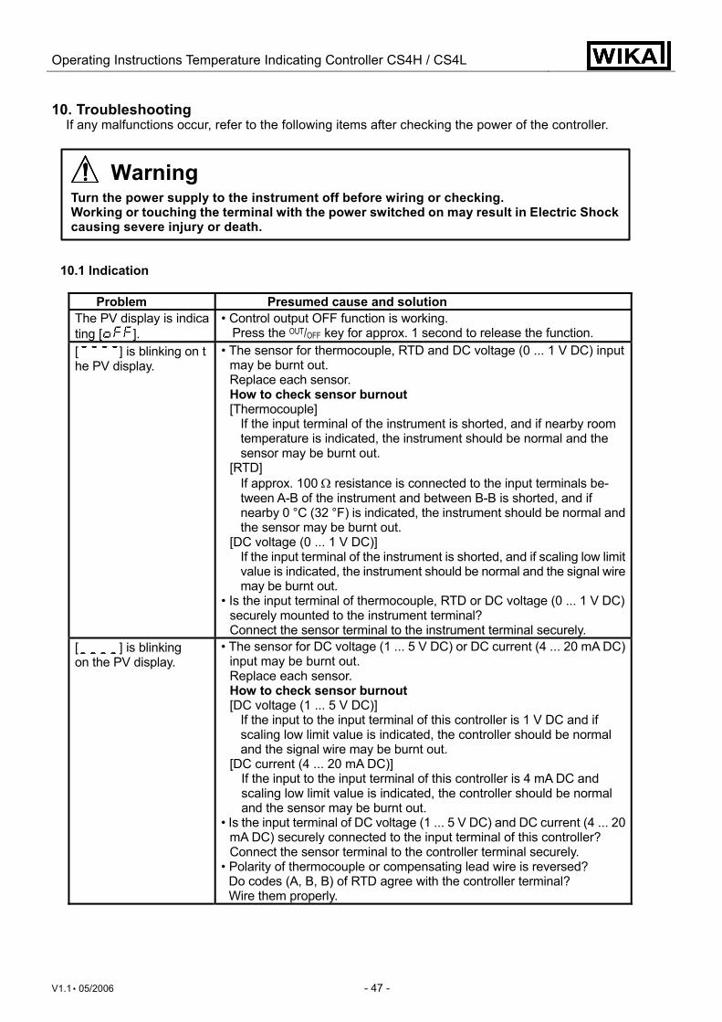
Operating Instructions Temperature Indicating Controller CS4H / CS4L
V1.1 • 05/2006 - 47 -
10. Troubleshooting If any malfunctions occur, refer to the following items after checking the power of the controller.
Warning
Turn the power supply to the instrument off before wiring or checking. Working or touching the terminal with the power switched on may result in Electric Shock causing severe injury or death.
10.1 Indication
Problem Presumed cause and solution The PV display is indicating [ ].
• Control output OFF function is working. Press the OUT/OFF key for approx. 1 second to release the function.
[ ] is blinking on the PV display.
• The sensor for thermocouple, RTD and DC voltage (0 ... 1 V DC) input may be burnt out. Replace each sensor. How to check sensor burnout [Thermocouple]
If the input terminal of the instrument is shorted, and if nearby room temperature is indicated, the instrument should be normal and the sensor may be burnt out.
[RTD] If approx. 100 Ω resistance is connected to the input terminals be-tween A-B of the instrument and between B-B is shorted, and if nearby 0 °C (32 °F) is indicated, the instrument should be normal and the sensor may be burnt out.
[DC voltage (0 ... 1 V DC)] If the input terminal of the instrument is shorted, and if scaling low limit value is indicated, the instrument should be normal and the signal wire may be burnt out.
• Is the input terminal of thermocouple, RTD or DC voltage (0 ... 1 V DC) securely mounted to the instrument terminal? Connect the sensor terminal to the instrument terminal securely.
[ ] is blinking on the PV display.
• The sensor for DC voltage (1 ... 5 V DC) or DC current (4 ... 20 mA DC) input may be burnt out. Replace each sensor. How to check sensor burnout [DC voltage (1 ... 5 V DC)]
If the input to the input terminal of this controller is 1 V DC and if scaling low limit value is indicated, the controller should be normal and the signal wire may be burnt out.
[DC current (4 ... 20 mA DC)] If the input to the input terminal of this controller is 4 mA DC and scaling low limit value is indicated, the controller should be normal and the sensor may be burnt out.
• Is the input terminal of DC voltage (1 ... 5 V DC) and DC current (4 ... 20 mA DC) securely connected to the input terminal of this controller? Connect the sensor terminal to the controller terminal securely.
• Polarity of thermocouple or compensating lead wire is reversed? Do codes (A, B, B) of RTD agree with the controller terminal? Wire them properly.
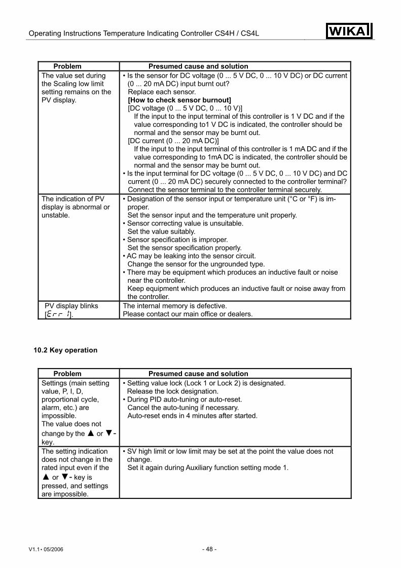
Operating Instructions Temperature Indicating Controller CS4H / CS4L
V1.1 • 05/2006 - 48 -
Problem Presumed cause and solution The value set during the Scaling low limit setting remains on the PV display.
• Is the sensor for DC voltage (0 ... 5 V DC, 0 ... 10 V DC) or DC current (0 ... 20 mA DC) input burnt out? Replace each sensor. [How to check sensor burnout] [DC voltage (0 ... 5 V DC, 0 ... 10 V)]
If the input to the input terminal of this controller is 1 V DC and if the value corresponding to1 V DC is indicated, the controller should be normal and the sensor may be burnt out.
[DC current (0 ... 20 mA DC)] If the input to the input terminal of this controller is 1 mA DC and if the value corresponding to 1mA DC is indicated, the controller should be normal and the sensor may be burnt out.
• Is the input terminal for DC voltage (0 ... 5 V DC, 0 ... 10 V DC) and DC current (0 ... 20 mA DC) securely connected to the controller terminal?Connect the sensor terminal to the controller terminal securely.
The indication of PV display is abnormal or unstable.
• Designation of the sensor input or temperature unit (°C or °F) is im-proper. Set the sensor input and the temperature unit properly.
• Sensor correcting value is unsuitable. Set the value suitably.
• Sensor specification is improper. Set the sensor specification properly.
• AC may be leaking into the sensor circuit. Change the sensor for the ungrounded type.
• There may be equipment which produces an inductive fault or noise near the controller. Keep equipment which produces an inductive fault or noise away from the controller.
PV display blinks [ ].
The internal memory is defective. Please contact our main office or dealers.
10.2 Key operation
Problem Presumed cause and solution Settings (main setting value, P, I, D, proportional cycle, alarm, etc.) are impossible. The value does not change by the ▲ or ▼- key.
• Setting value lock (Lock 1 or Lock 2) is designated. Release the lock designation.
• During PID auto-tuning or auto-reset. Cancel the auto-tuning if necessary. Auto-reset ends in 4 minutes after started.
The setting indication does not change in the rated input even if the ▲ or ▼- key is pressed, and settings are impossible.
• SV high limit or low limit may be set at the point the value does not change. Set it again during Auxiliary function setting mode 1.
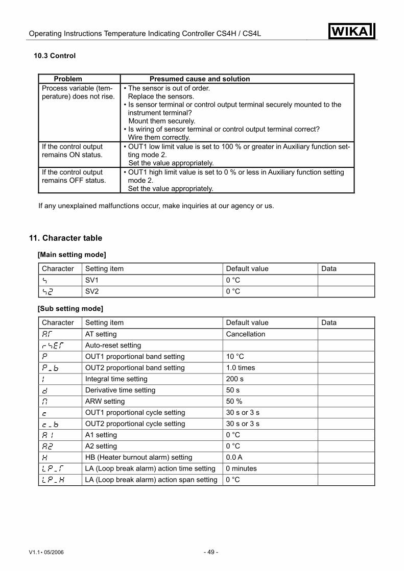
Operating Instructions Temperature Indicating Controller CS4H / CS4L
V1.1 • 05/2006 - 49 -
10.3 Control
Problem Presumed cause and solution Process variable (tem-perature) does not rise.
• The sensor is out of order. Replace the sensors.
• Is sensor terminal or control output terminal securely mounted to the instrument terminal? Mount them securely.
• Is wiring of sensor terminal or control output terminal correct? Wire them correctly.
If the control output remains ON status.
• OUT1 low limit value is set to 100 % or greater in Auxiliary function set-ting mode 2. Set the value appropriately.
If the control output remains OFF status.
• OUT1 high limit value is set to 0 % or less in Auxiliary function setting mode 2. Set the value appropriately.
If any unexplained malfunctions occur, make inquiries at our agency or us.
11. Character table
[Main setting mode]
Character Setting item Default value Data
SV1 0 °C
SV2 0 °C [Sub setting mode]
Character Setting item Default value Data
AT setting Cancellation
Auto-reset setting
OUT1 proportional band setting 10 °C
OUT2 proportional band setting 1.0 times
Integral time setting 200 s
Derivative time setting 50 s
ARW setting 50 %
OUT1 proportional cycle setting 30 s or 3 s
OUT2 proportional cycle setting 30 s or 3 s
A1 setting 0 °C
A2 setting 0 °C
HB (Heater burnout alarm) setting 0.0 A
LA (Loop break alarm) action time setting 0 minutes
LA (Loop break alarm) action span setting 0 °C
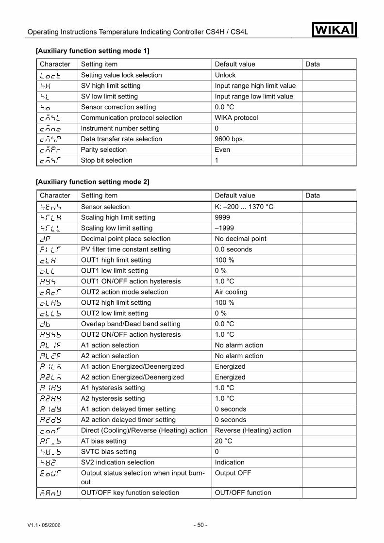
Operating Instructions Temperature Indicating Controller CS4H / CS4L
V1.1 • 05/2006 - 50 -
[Auxiliary function setting mode 1]
Character Setting item Default value Data
Setting value lock selection Unlock
SV high limit setting Input range high limit value
SV low limit setting Input range low limit value
Sensor correction setting 0.0 °C
Communication protocol selection WIKA protocol
Instrument number setting 0
Data transfer rate selection 9600 bps
Parity selection Even
Stop bit selection 1
[Auxiliary function setting mode 2]
Character Setting item Default value Data
Sensor selection K: –200 ... 1370 °C
Scaling high limit setting 9999
Scaling low limit setting –1999
Decimal point place selection No decimal point
PV filter time constant setting 0.0 seconds
OUT1 high limit setting 100 %
OUT1 low limit setting 0 %
OUT1 ON/OFF action hysteresis 1.0 °C
OUT2 action mode selection Air cooling
OUT2 high limit setting 100 %
OUT2 low limit setting 0 %
Overlap band/Dead band setting 0.0 °C
OUT2 ON/OFF action hysteresis 1.0 °C
A1 action selection No alarm action
A2 action selection No alarm action
A1 action Energized/Deenergized Energized
A2 action Energized/Deenergized Energized
A1 hysteresis setting 1.0 °C
A2 hysteresis setting 1.0 °C
A1 action delayed timer setting 0 seconds
A2 action delayed timer setting 0 seconds
Direct (Cooling)/Reverse (Heating) action Reverse (Heating) action
AT bias setting 20 °C
SVTC bias setting 0
SV2 indication selection Indication
Output status selection when input burn-out
Output OFF
OUT/OFF key function selection OUT/OFF function