Embed Size (px)
Citation preview
TEMPEST Low Emission Controlled Design
Dr. Bruce C. Gabrielson, NCE
Last Updated: 2002
Based on the Texts:
TEMPEST, A Description and Approach
Hardwire and Cable Design in Secure Communications
TEMPEST Hardware Design
TEMPEST Systems Engineering & Program Management
INFOSEC Engineering
Volume 4 – Facilities
TEMPEST Isolation in Secure Facilities, Compartmented Facilities, and Portable Shelters
Isolation Need Based on Paper: Assessing the Need for Shielding at Secure Data Processing Facilities (Vulnerability Assessments) and Possible Problem Solutions – Bruce Gabrielson
Bruce Gabrielson, PhD
Last Updated: 2002
Assess the TEMPEST Impact
Although there has been a redirection in the impact of TEMPEST countermeasures and requirements, neither the requirements nor the demonstrated need have ever disappeared.
There usually exists a requirement to provide a risk assessment concerning just how secure emissions from equipment operating in the controlled area really are.
TEMPEST Site Survey
The TEMPEST site survey is intended to evaluate how much protection is needed at a given location. Site surveys, although acceptable to meet
most requirements, are seldom based on a comprehensive emanation attenuation analysis.
Stating that there is no risk since an unobserved receiver can’t get close enough to detect a signal is a risk in itself.
Facility TEMPEST Analysis
This section presents a risk evaluation of the TEMPEST design for equipment installed in a specific location.
The analysis can show that the inherent design of the facilities where equipment is located will satisfy TEMPEST requirements with no additional design consideration.
TEMPEST Vulnerability Analysis Fundamentals
A formal TEMPEST vulnerability analysis takes into account: Potential source emission levels
Structure attenuation
Aperture losses due to windows and doors
Space loss to a possible covert receiver
Impact of fortuitous conductors
“Inspectable” space
TEMPEST Zone ratings automatically consider these individual loss elements.
Inspectable Space
Understanding the Inspectable space qualifier is important when determining the level of countermeasures required.
The definition is:
Inspectable Space (IS): The three dimensional space surrounding equipment that processes classified and/or sensitive information. Space within which legal authority to identify and/or remove a potential exploitation exists or TEMPEST exploitation is not considered practical.
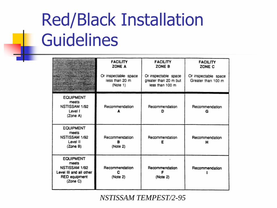
Red/Black Installation Guidelines
NSTISSAM TEMPEST/2-95
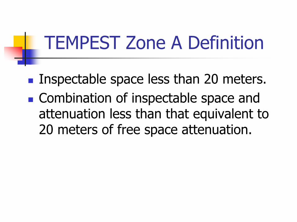
TEMPEST Zone A Definition
Inspectable space less than 20 meters.
Combination of inspectable space and attenuation less than that equivalent to 20 meters of free space attenuation.
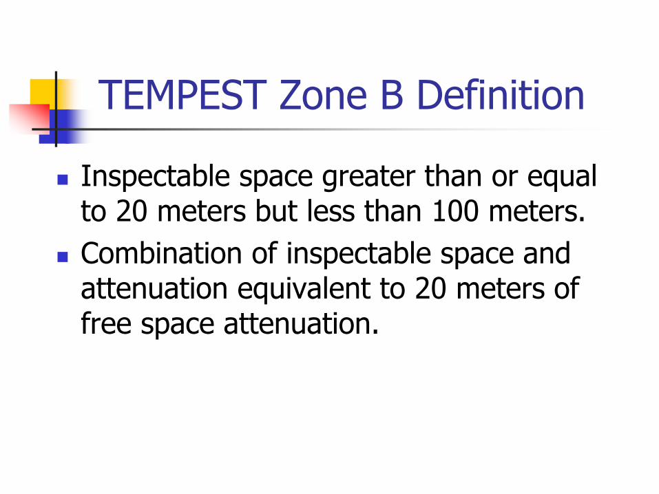
TEMPEST Zone B Definition
Inspectable space greater than or equal to 20 meters but less than 100 meters.
Combination of inspectable space and attenuation equivalent to 20 meters of free space attenuation.
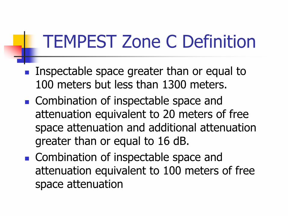
TEMPEST Zone C Definition
Inspectable space greater than or equal to 100 meters but less than 1300 meters.
Combination of inspectable space and attenuation equivalent to 20 meters of free space attenuation and additional attenuation greater than or equal to 16 dB.
Combination of inspectable space and attenuation equivalent to 100 meters of free space attenuation
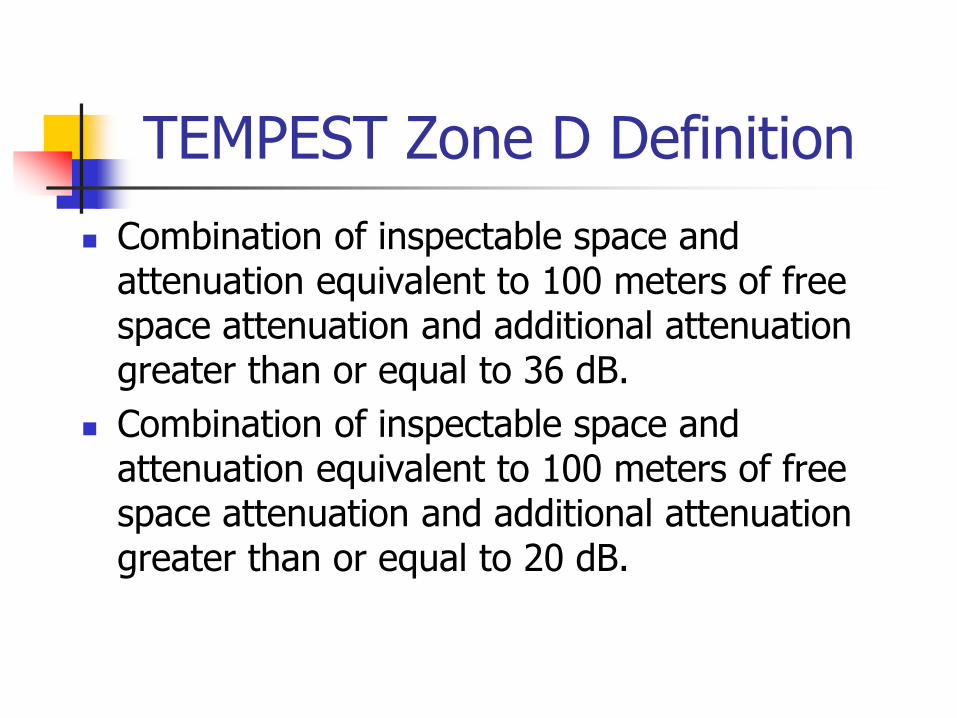
TEMPEST Zone D Definition
Combination of inspectable space and attenuation equivalent to 100 meters of free space attenuation and additional attenuation greater than or equal to 36 dB.
Combination of inspectable space and attenuation equivalent to 100 meters of free space attenuation and additional attenuation greater than or equal to 20 dB.
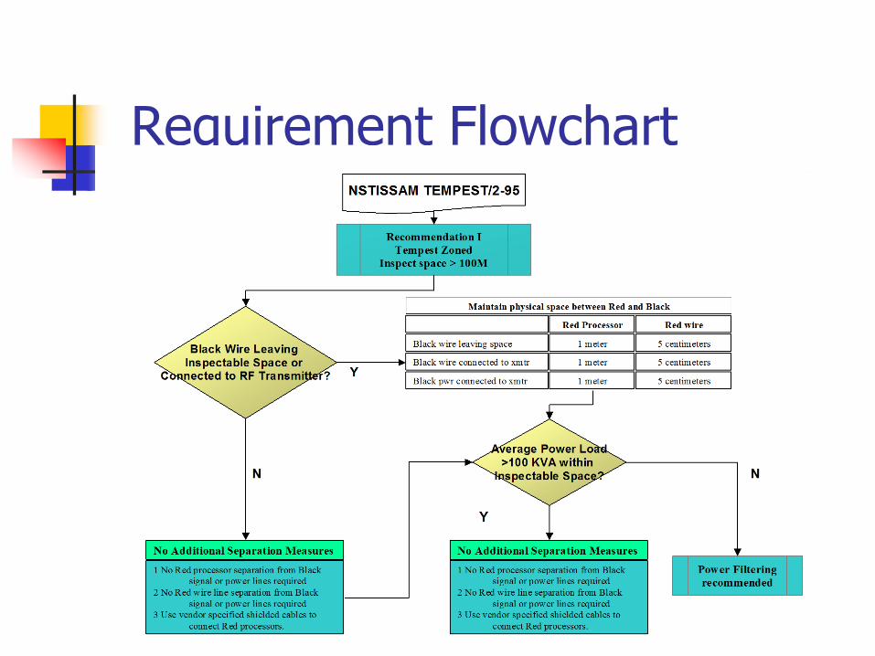
Requirement Flowchart
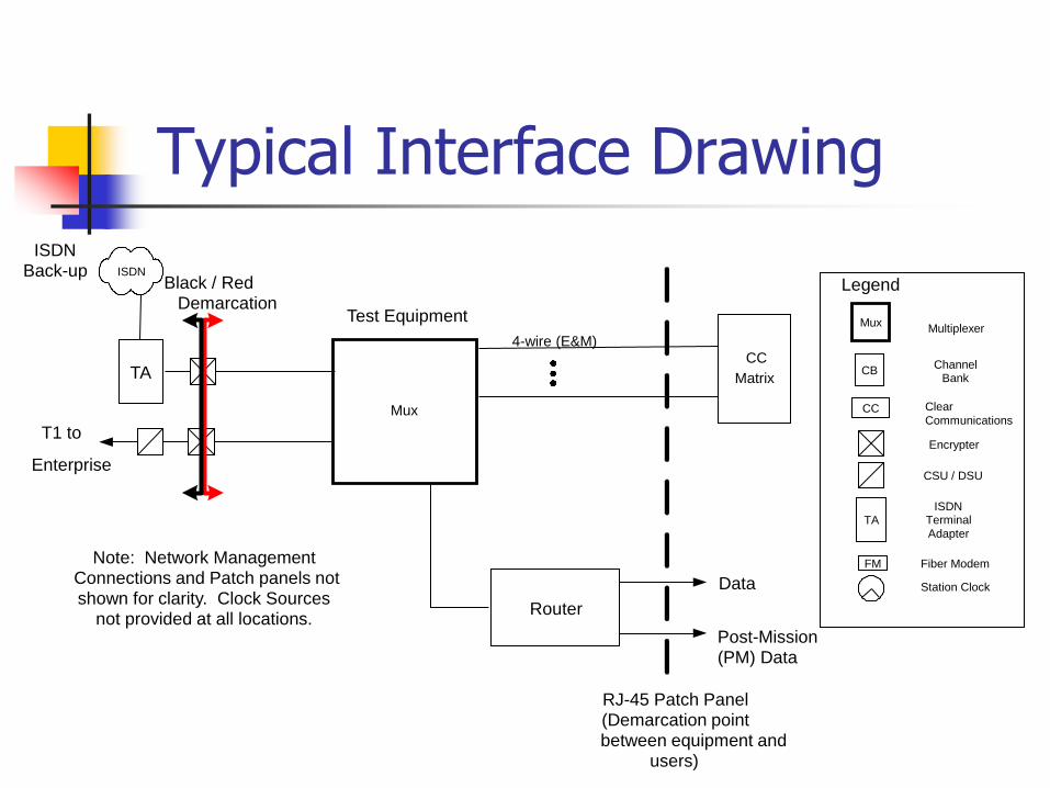
Typical Interface Drawing
Mux
Test Equipment
Note: Network Management Connections and Patch panels not shown for clarity. Clock Sources
not provided at all locations.
4-wire (E&M) CC
Matrix
T1 to
Enterprise
TA
ISDN
Mux Multiplexer
CB Channel
Bank
CC Clear
Communications
Station Clock
Encrypter
Fiber Modem
Legend
CSU / DSU
FM
TA
ISDN
Terminal Adapter
Router
ISDN
Back-up
RJ-45 Patch Panel (Demarcation point between equipment and
users)
Black / Red
Demarcation
Data
Post-Mission
(PM) Data
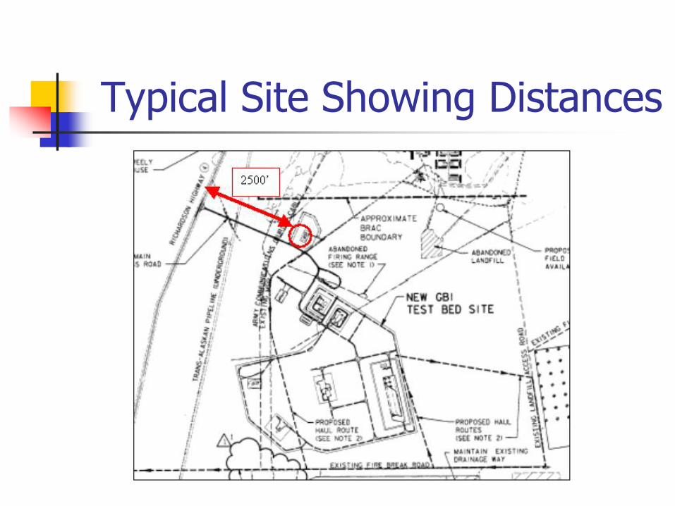
Typical Site Showing Distances
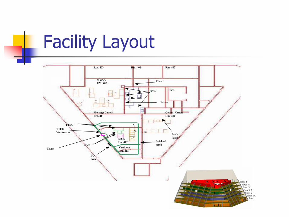
Facility Layout
TTEC
TTEC
Workstation
ESCN
Rm. 412
Vestibule
Rm. 413
Comm. Center
Rm. 410
I/O
Panel
Shielded
Area
Message Center
Rm. 411
Floor 4 Floor 3A
Floor 3 Floor 2A
Floor 2
Floor 1A Floor 1
LHC
CNE
MWOC
RM. 402
Rm. 405
Rm. 403 Rm. 406 Rm. 407
Elev. DCPs
Printer
Printer
Patch
Panel
Phone
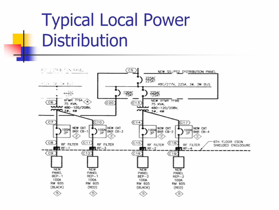
Typical Local Power Distribution
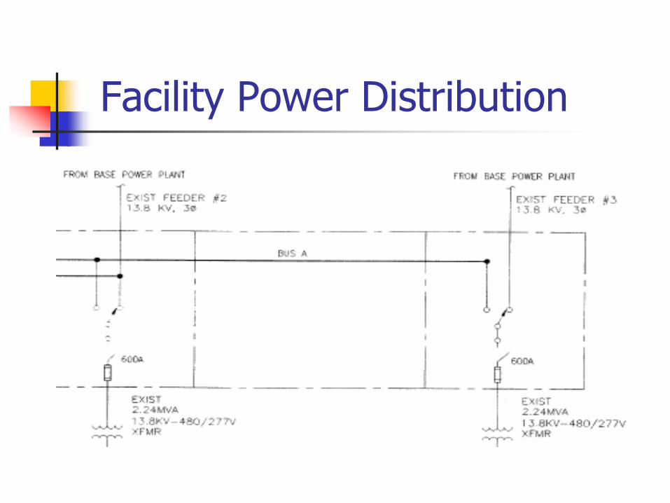
Facility Power Distribution
Environmental Shielding
Non-reinforced concrete, block wall, and brick provide no attenuation below 300 MHz and about 5 DB above 300 MHz.
I-Beam girder construction when beams are grounded provides shielding depending on the girder spacing (20 DB average).
Since common construction materials provide little attenuation above 30 MHZ, additional shielding is nearly always necessary.
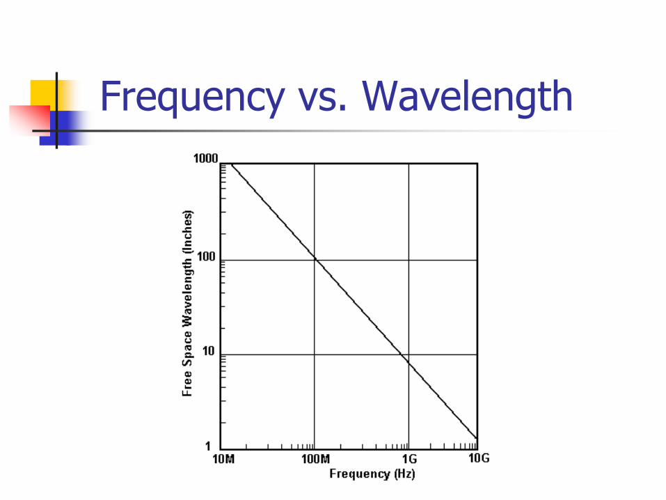
Frequency vs. Wavelength
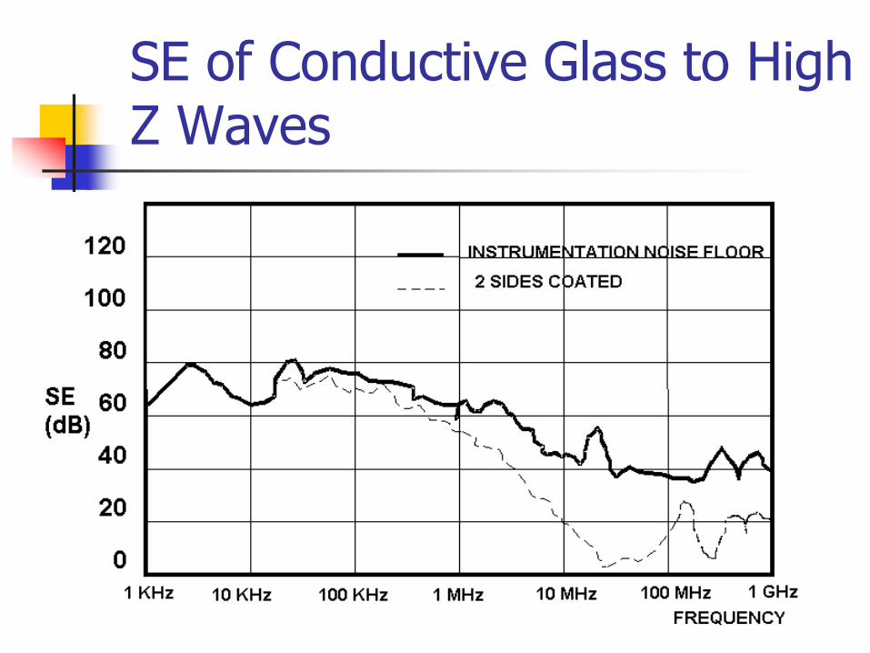
SE of Conductive Glass to High Z Waves
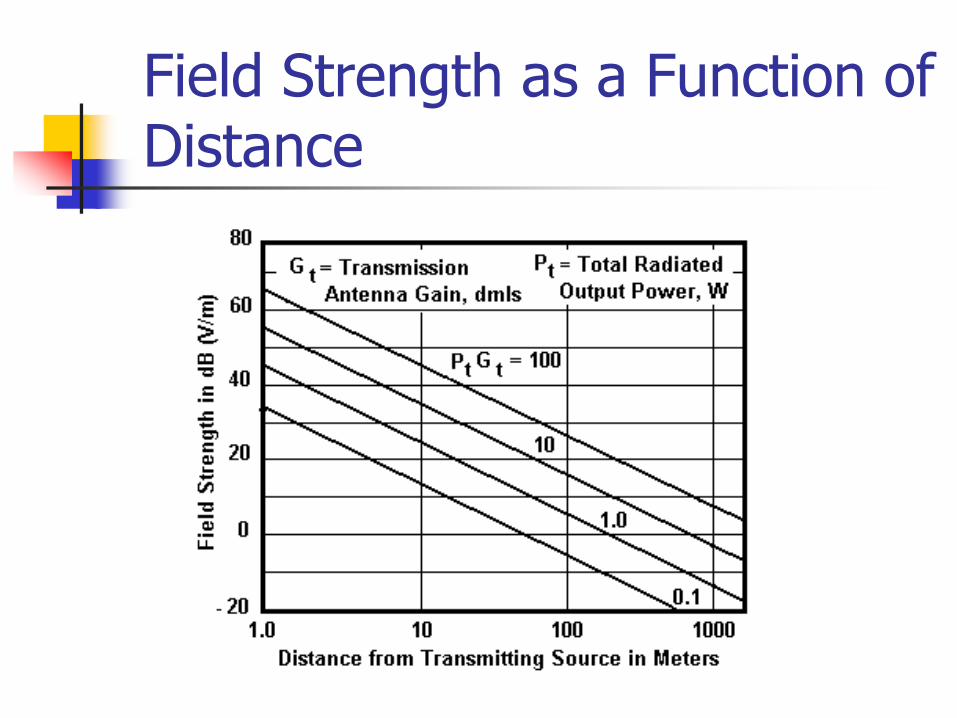
Field Strength as a Function of Distance

Shielded Rooms & Enclosures
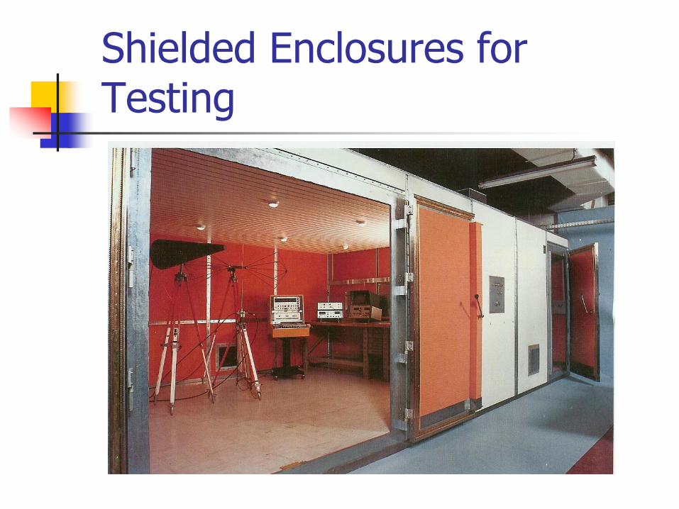
Shielded Enclosures for Testing
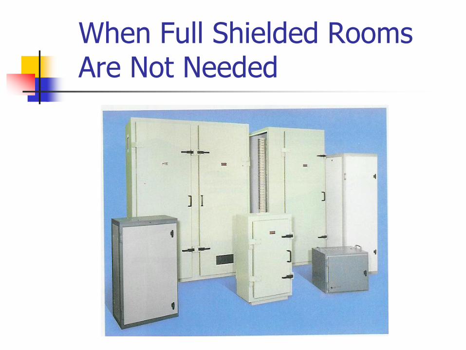
When Full Shielded Rooms Are Not Needed
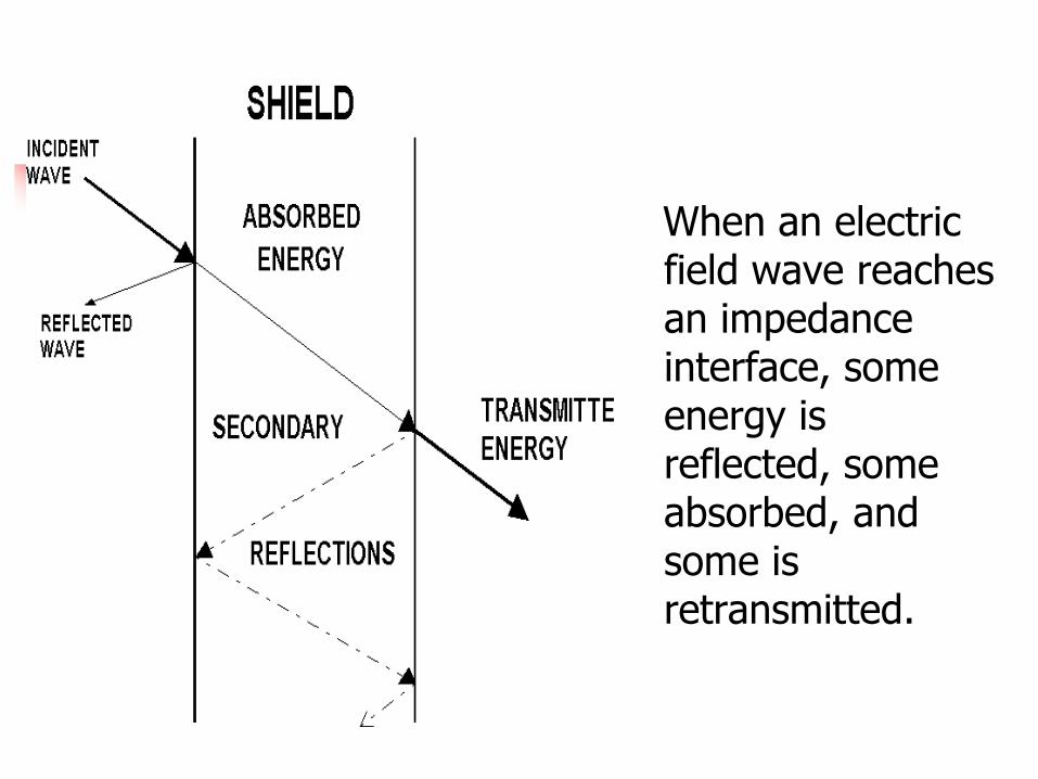
When an electric field wave reaches an impedance interface, some energy is reflected, some absorbed, and some is retransmitted.
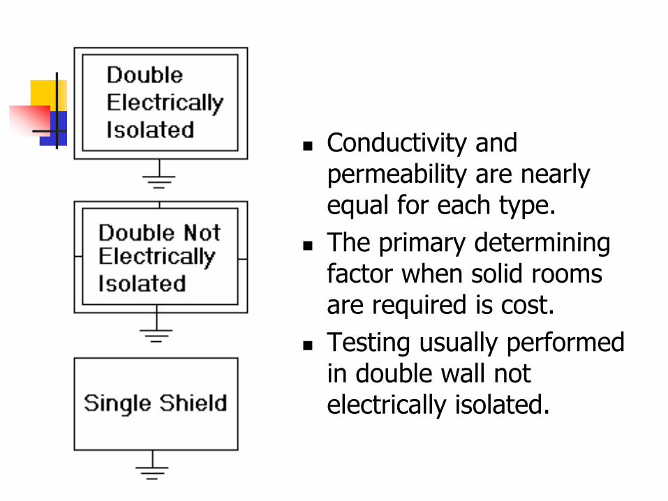
Conductivity and permeability are nearly equal for each type.
The primary determining factor when solid rooms are required is cost.
Testing usually performed in double wall not electrically isolated.
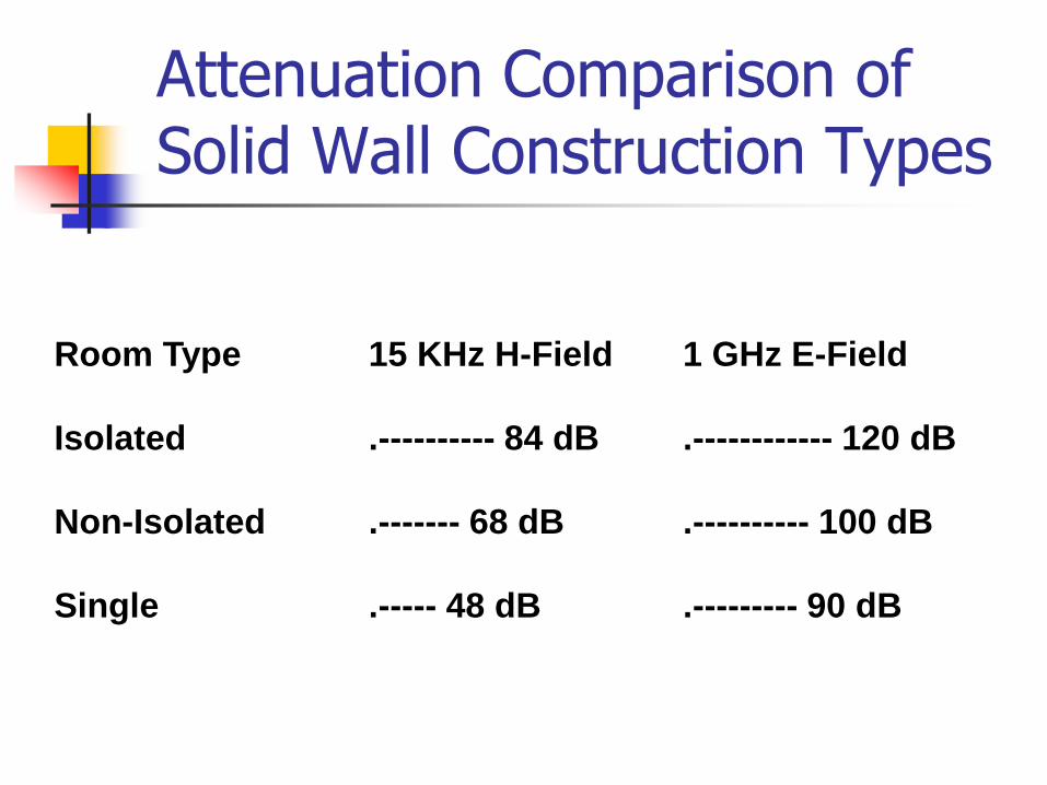
Attenuation Comparison of Solid Wall Construction Types
Room Type 15 KHz H-Field 1 GHz E-Field
Isolated .---------- 84 dB .------------ 120 dB
Non-Isolated .------- 68 dB .---------- 100 dB
Single .----- 48 dB .--------- 90 dB
Thin Shields
It is possible in some instances to provide significant shielding effectiveness to an existing structure through the use of multiple thin layer shields located at successive locations within the structure.
The general approach is to use environmental foil covered drywall with conductive tape and screws to the underlying metal studs.

Multi-Layered Thin Shields
Nested Shields
Reflection Loss includes the reflections at both surfaces, and is independent of thickness.
For shields with 10 DB or higher absorption loss, the energy reflected back into the shield does not contribute significantly to attenuation.
For low absorption loss shields such as nested thin shields, the reflected and re-reflected losses become significant.
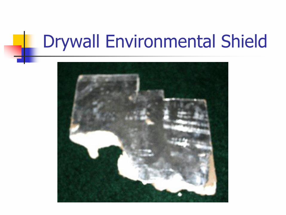
Drywall Environmental Shield
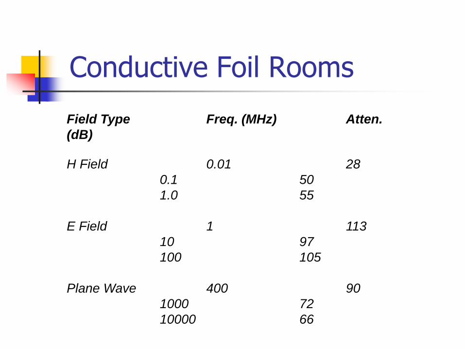
Conductive Foil Rooms
Field Type Freq. (MHz) Atten.
(dB)
H Field 0.01 28
0.1 50
1.0 55
E Field 1 113
10 97
100 105
Plane Wave 400 90
1000 72
10000 66
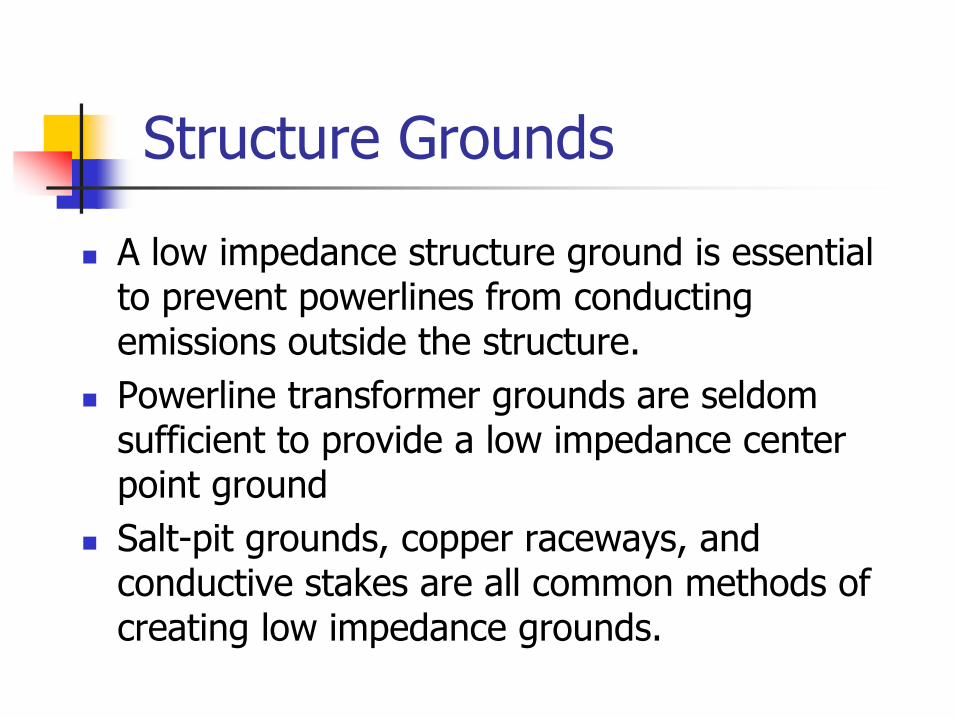
Structure Grounds
A low impedance structure ground is essential to prevent powerlines from conducting emissions outside the structure.
Powerline transformer grounds are seldom sufficient to provide a low impedance center point ground
Salt-pit grounds, copper raceways, and conductive stakes are all common methods of creating low impedance grounds.
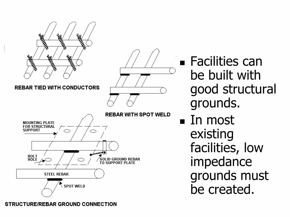
Facilities can be built with good structural grounds.
In most existing facilities, low impedance grounds must be created.
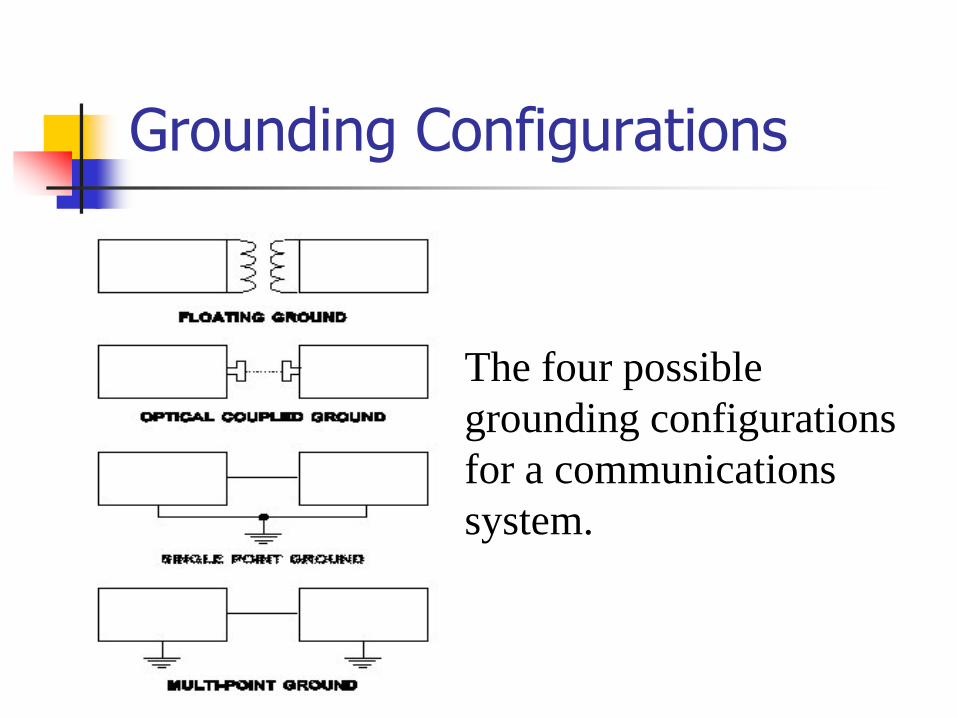
Grounding Configurations
The four possible
grounding configurations
for a communications
system.
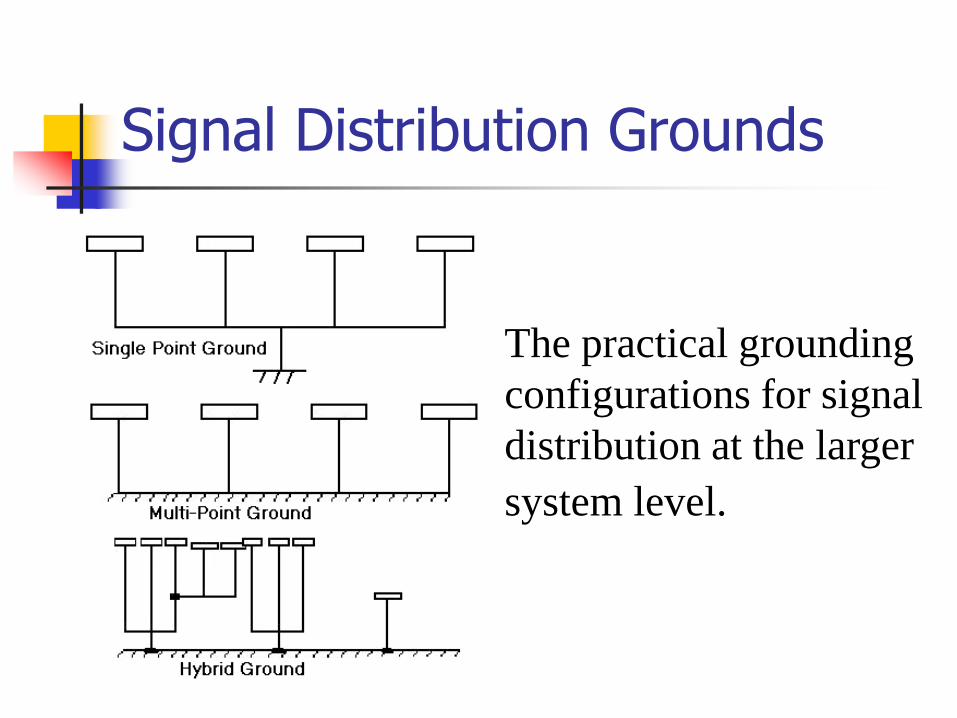
Signal Distribution Grounds
The practical grounding
configurations for signal
distribution at the larger
system level.
Protection Layers
Ground isolation between power systems and communication systems at either the box or system level is the primary protective barrier between two layers in the protected environment.
At the macro level, facilities which process protected information are usually required to provide some level of security protection, often including internally partitioned isolation.
Purpose of a Power System
• Transform or generate and route power into the facility, especially during the absence of commercial power.
• Switch between the two sources of power as required.
• Condition the electrical power for the critical loads being served.
• Distribute appropriate electrical power to the various equipment throughout the facility
Powerline Distribution Guidance
Powerlines should be contained within the inspectable space whenever the average power load is less than 100 KVA.
If this is not possible, the CTTA must conduct a review to determine whether power line filters should be recommended.
For existing facilities, the CTTA may request a TEMPEST test be performed to assist in arriving at the recommendations.
RED-BLACK Powerline Guidance
RED processors should not be powered from the same circuits as RF transmitters or BLACK equipment with signal lines that exit the inspectable space. Except when either the RED equipment of the RF
transmitters and BLACK equipment with signal lines that exit the inspectable space are equipped with power line filters.
RED processors should be separated from RF transmitters by a minimum of three meters.
Control Subsystem
Many control subsystems are self-contained and independent.
For example, intrusion detectors that sound alarms.
In terms of grounding, the large diversity of the control subsystem results in various grounding paths being established.
Control Subsystem Grounds
Small control devices are typically grounded through the ac safety ground provided via the power outlet.
More automated and complex subsystems resemble a computer network or a communication subsystem.
Communications Subsystem
This subsystem is the network of electronic equipment, interfaces, and antennas whose elements are located both in, and around, the C3I facility.
The purpose of the subsystem is to transfer information from one point to another.
Information transfer may take place between points located within the facility or between different facilities.
Communications & Power Subsystem Grounds
The equipment of the various communication elements is likely to be distributed throughout the facility and grounded at multiple points.
The equipment cases, racks, and frames are grounded to the ac power ground, to raceways and conduit, and to structural members at numerous locations within the facility.
A single point configuration for the signal reference ground is implemented for telephone circuits and for data processing circuits only.
Data Processing Subsystem
Data processing subsystems are configured in various ways resulting in a myriad of different grounding connections being established.
Where I/O and other peripherals are separated by large distances from the processor, multiple connections to the facility ground network result.
Criteria for Determining Low Emission Cable Problem
If interconnecting cables are more than 10% the length of the wavelength of the signals carried (or any coupled signals which might also be present), the potential for a radiated problem exists.
In Reality
A single point ground configuration does not exist because of internal grounding of signal references to cabinets and enclosures with subsequent interconnections to power conduits and raceways, and because of the use of unbalanced interfaces between the various pieces of equipment. The effective signal reference ground for the communication
subsystem in the typical C3I facility is a multipoint grounded system with numerous interconnections between signal references, equipment enclosures, raceways, conduit, and structural members.
Practical Noise Solving Approach
Don’t try to implement a "single point" ground connection for your main processor.
Instead, try to minimize the stray current in the ground reference system and use effective common mode suppression techniques and devices in data paths.
Basic Rules for Signal Security Existing Facilities
Conduct a detailed survey of ALL grounding networks and bonds in the facility including: Power safety grounds, connections to the earth
electrode subsystem to include water pipes and lightning protection ground rods, utility pipe interconnections
Electronic equipment grounds to include the interconnections with the power safety grounding subsystem, tower grounds, and building and structural interconnections with the grounding networks must be accurately defined.
Basic Rule 2 for Signal Security
Carefully examine all accessible bonds for looseness and evidence of corrosion.
Clean and tighten all deficient bonds.
Measure a representative sampling of bonds using the procedures of MIL-HDBK-419A, Volume II.
Basic Rule 3 for Signal Security
Measure the stray AC current levels on accessible conductors of the fault protection subsystem and on electronic equipment signal ground conductors.
Any stray power current readings in excess of 1 ampere should be thoroughly checked out to find the cause.
Basic Rules 4-5 for Signal Security
Compare the updated as-built grounding drawings with the recommendations contained in this document.
Evaluate cost and operational impacts of upgrading the facility grounding networks and bond networks as recommended, including the installation of an EESS as described in MIL-HDBK 232A.
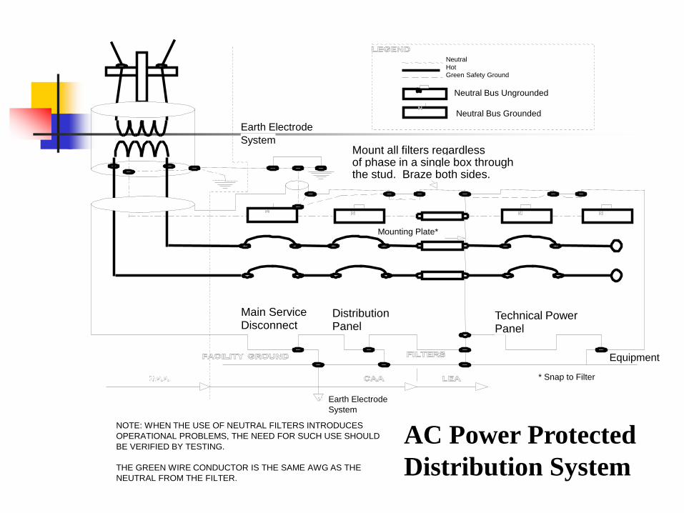
Technical Power Panel
Distribution
Panel
Main Service
Disconnect
Equipment
Mount all filters regardless of phase in a single box through the stud. Braze both sides.
Earth Electrode
System
Neutral
Hot Green Safety Ground
Neutral Bus Ungrounded
Neutral Bus Grounded
Mounting Plate*
* Snap to Filter
Earth Electrode
System
NOTE: WHEN THE USE OF NEUTRAL FILTERS INTRODUCES
OPERATIONAL PROBLEMS, THE NEED FOR SUCH USE SHOULD
BE VERIFIED BY TESTING.
THE GREEN WIRE CONDUCTOR IS THE SAME AWG AS THE
NEUTRAL FROM THE FILTER.
AC Power Protected
Distribution System
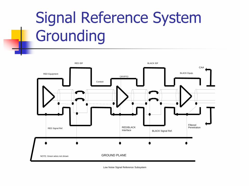
Signal Reference System Grounding
Low Noise Signal Reference Subsystem
NOTE: Green wires not shown GROUND PLANE
RED Equipment
Conduit
CRYPTO
RED Signal Ref. RED/BLACK
Interface BLACK Signal Ref.
Filtered Penetration
BLACK IDF
BLACK Equip.
CAA
RED IDF
Good Facility Engineering
Safety requirements are met.
Undesirable ground loops are avoided.
No inadvertent security penetrations result through fortuitous means via the ground system.
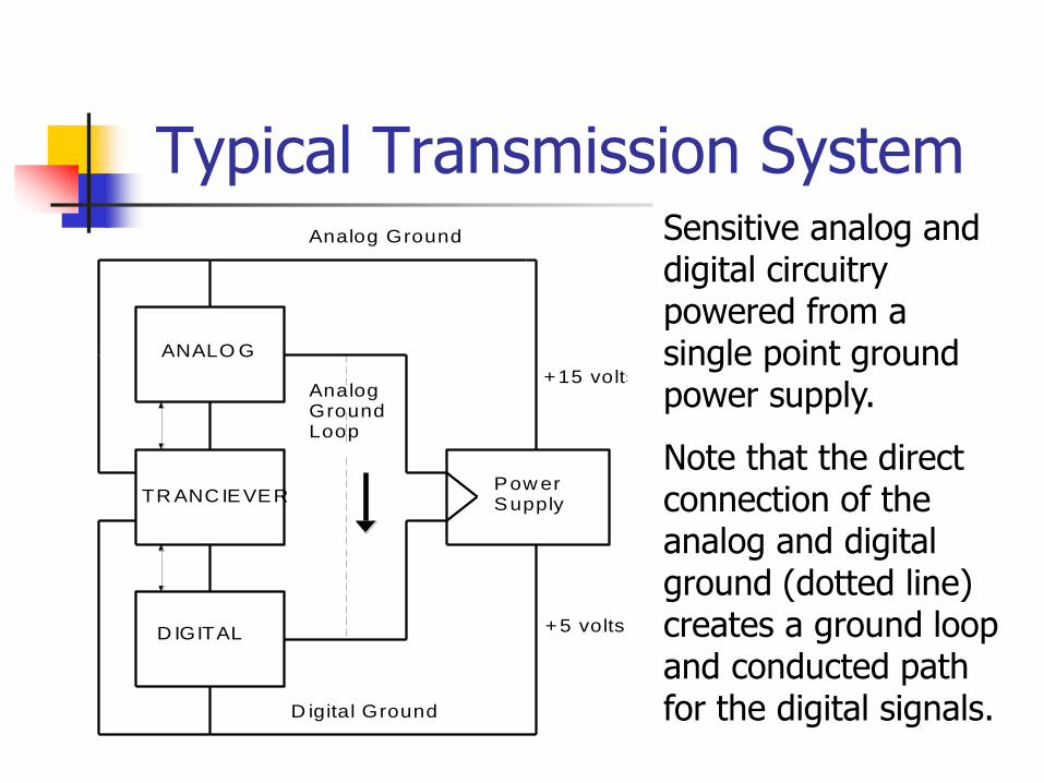
Typical Transmission System
ANALO G
TR ANC IEVER
D IGITAL
Analog Ground
+15 volts
Pow erSupply
+5 volts
AnalogGroundLoop
D igital Ground
Sensitive analog and digital circuitry powered from a single point ground power supply.
Note that the direct connection of the analog and digital ground (dotted line) creates a ground loop and conducted path for the digital signals.
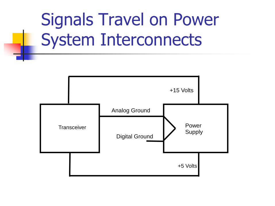
Signals Travel on Power System Interconnects
Analog Ground
Digital Ground
Power Supply
+5 Volts
+15 Volts
Transceiver
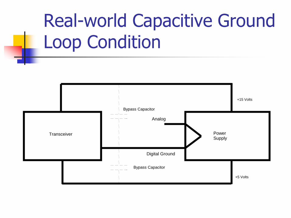
Real-world Capacitive Ground Loop Condition
Bypass Capacitor
+15 Volts
+5 Volts
Power Supply
Bypass Capacitor
Transceiver
Digital Ground
Analog
Network Protection
Network Connections
Depending on the security requirements imposed, security of a network can be provided in the form of emission control, encryption, physical protection, or a combination of each.
In the majority of cases, emission suppression on the central server is not employed.
The ring network has switching elements distributed along the ring, with nodes connecting to each element.
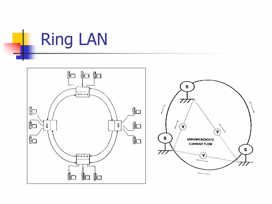
Ring LAN
Emission Problems With Ring LANs
Since ground potentials differ at nearly every location along the ring, common mode ground loops are created among the various nodes connected, greatly reducing the emission controls implemented at each node.
Differential line drivers are prone to the effects of offset voltages.
Therefore, twisted wire by itself does not reduce the transmitted signal sufficiently to eliminate radiated emission problems.
Network Security Guidelines
Protecting the entire network involves the consideration of three design factors. First, each individual component in the network
must be protected, either as a separate emission secure device, or through SCIF or vault isolation.
Second, the hardwired paths between each component must be protected by encrypting, emission shielding, or physical isolation (which could include facility shielding).
The third factor involves the power and ground system used in the facility.
Emission Secure RED/BLACK Facilities
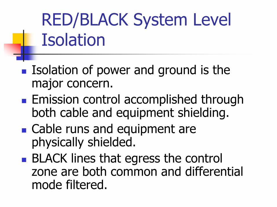
RED/BLACK System Level Isolation
Isolation of power and ground is the major concern.
Emission control accomplished through both cable and equipment shielding.
Cable runs and equipment are physically shielded.
BLACK lines that egress the control zone are both common and differential mode filtered.
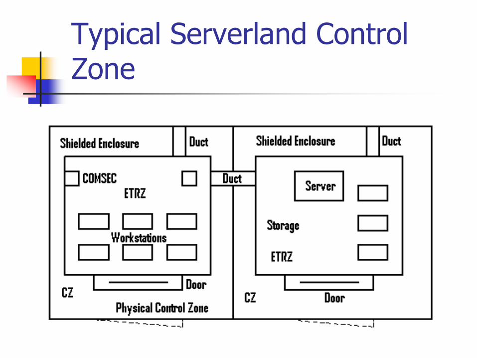
Typical Serverland Control Zone
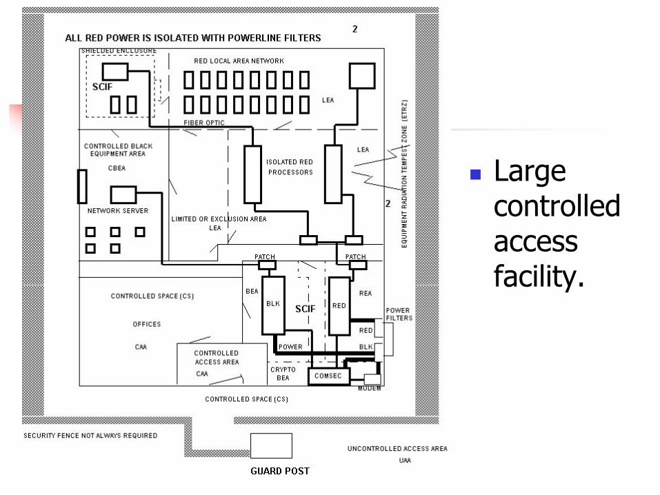
Large controlled access facility.
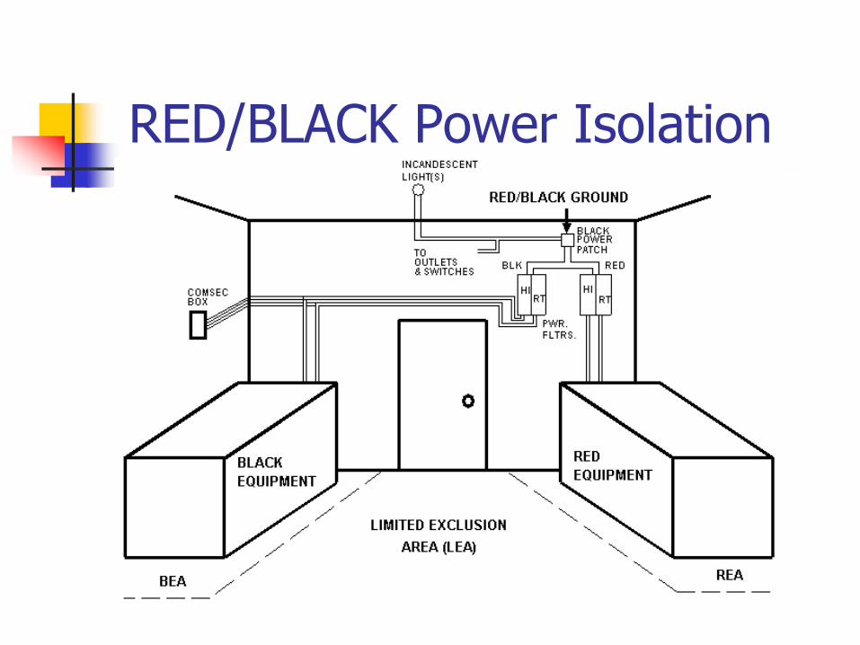
RED/BLACK Power Isolation
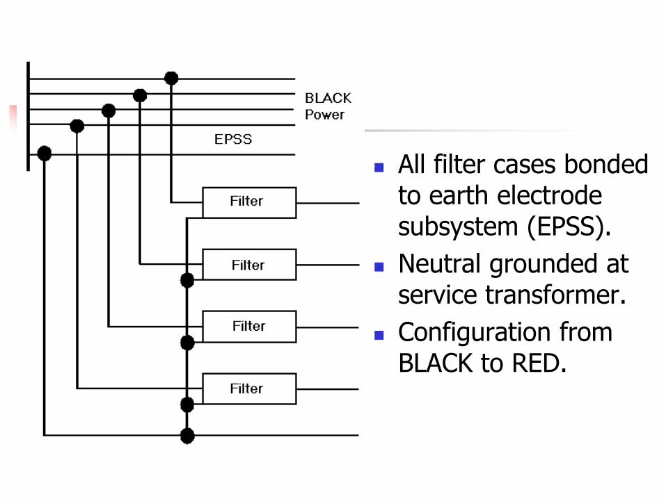
All filter cases bonded to earth electrode subsystem (EPSS).
Neutral grounded at service transformer.
Configuration from BLACK to RED.
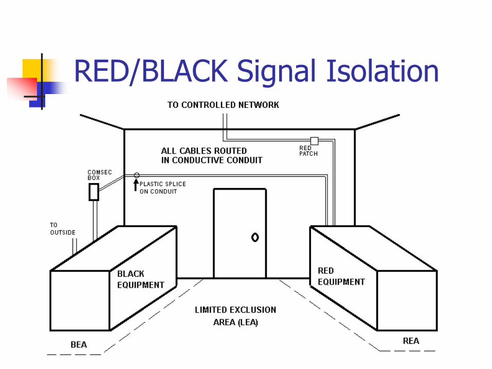
RED/BLACK Signal Isolation
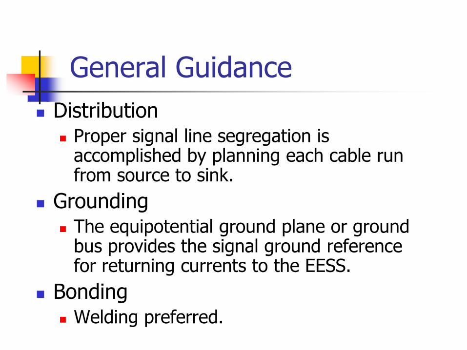
General Guidance
Distribution Proper signal line segregation is
accomplished by planning each cable run from source to sink.
Grounding The equipotential ground plane or ground
bus provides the signal ground reference for returning currents to the EESS.
Bonding Welding preferred.
Sensitive Compartmented Information Facilities
SCIF Designs
A SCIF is used to compartmentalize and contain specific levels of classified information processing equipment and operations.
The US requirements document, DIAM 50-3, is applicable to secure working areas, temporary secure areas, and some special access control areas. Physical Security Standards for Sensitive
Compartmented Information Facilities, Defense Intelligence Agency Manual (DIAM) 50-3. Implements the requirements of USIB-D-9-1/20
General Guidance - Security
Security is implemented within a SCIF through the use of countermeasures directed at the critical primary areas of grounding, bonding, shielding and cable distribution.
Each of these primary areas are interactive.
Grounding and cable distribution effects how shield currents and offset voltages interact.
Bonding effects shielding characteristics as well as current flow.
General Guidance - EESS
The equipotential ground plane or ground bus provides the signal ground reference for returning currents to their source, or for referencing to the facilities Earth Electrode Subsystem (EESS). For a facility, the EESS can be a ground driven rod
network, building structural steel, a metallic cold water pipe, or any other continuous metallic structure.
The intent is to make this one point the lowest impedance point for any extraneous currents which may be flowing from any source.
General Guidance - Bonding
Welding is the preferred bonding method over pressure bonds. As was the case with attaching cable shields
to backshells, a poor bond will hamper a nonferrous metal shields ability to contain radiated electric signals as well as cause reflected currents to flow in alternate paths.
Ferrous metals that are used to control magnetic fields do not require low impedance bonds to ground.
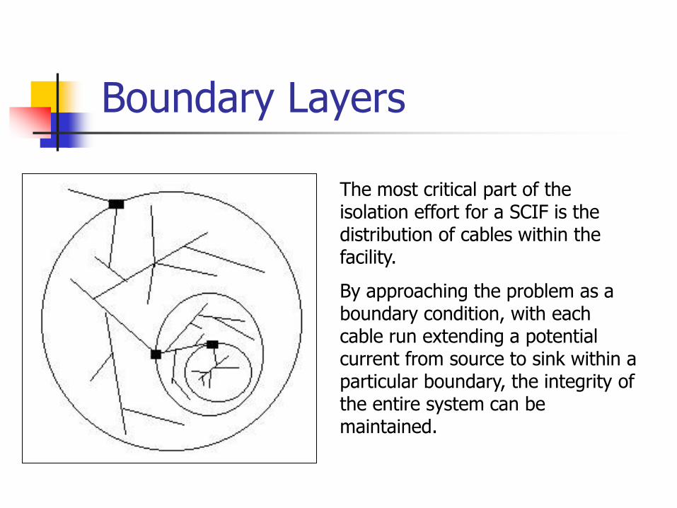
Boundary Layers
The most critical part of the isolation effort for a SCIF is the distribution of cables within the facility.
By approaching the problem as a boundary condition, with each cable run extending a potential current from source to sink within a particular boundary, the integrity of the entire system can be maintained.
Design at Both The System and Interface Level
At the system level cable runs require physical isolation for the highest level of security.
Cable runs should be shielded and should not be configured parallel if possible. Digital interfaces are usually implemented
with fiber optics, twisted shielded pair (TSP) or coax (for higher frequency communications).
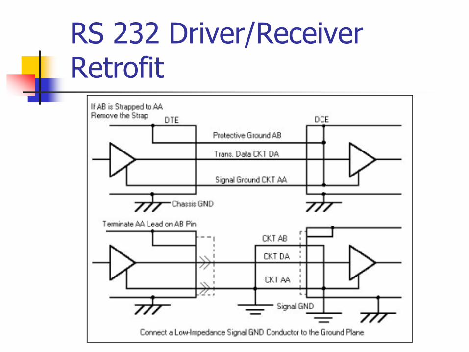
RS 232 Driver/Receiver Retrofit
Telephone Security
All incoming telephone cables that penetrate the SCIF must enter through one opening.
RED phones should use a positive disconnect plug and jack.
In general, the use of phones in a SCIF is discouraged.
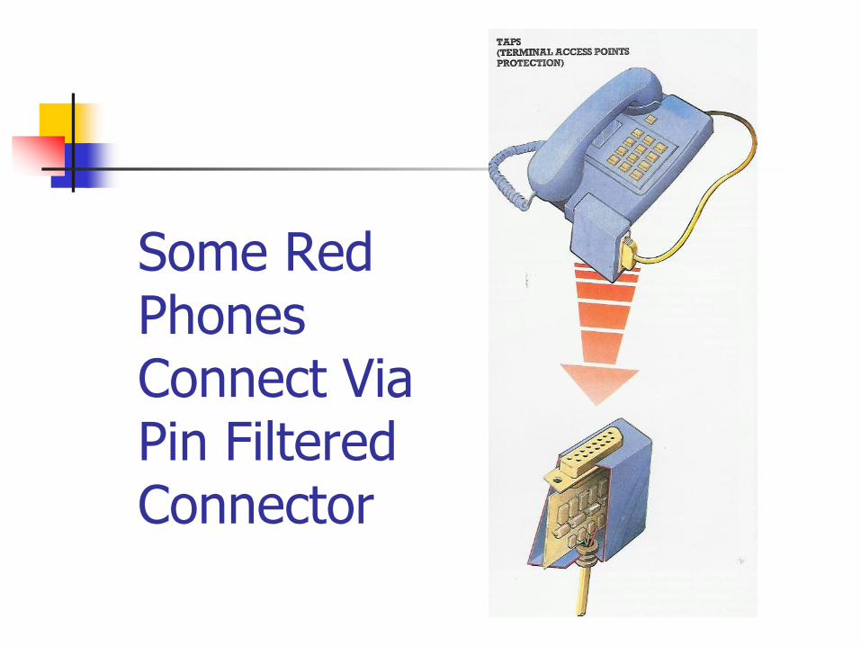
Some Red Phones Connect Via Pin Filtered Connector
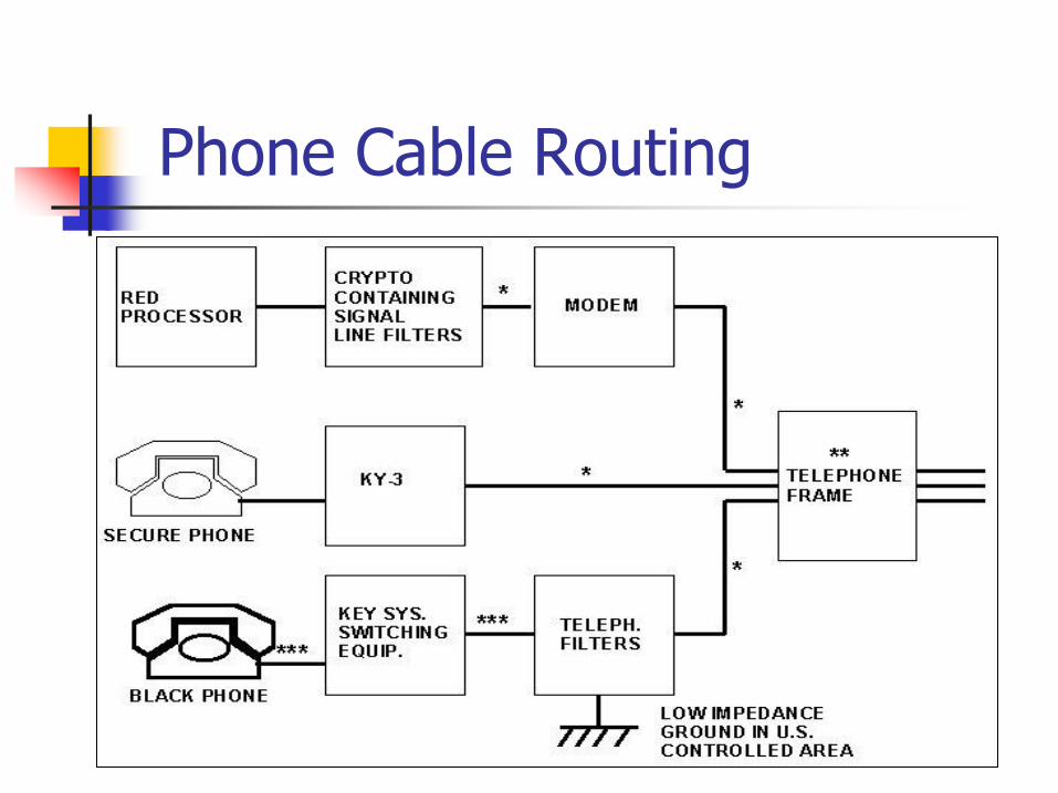
Phone Cable Routing
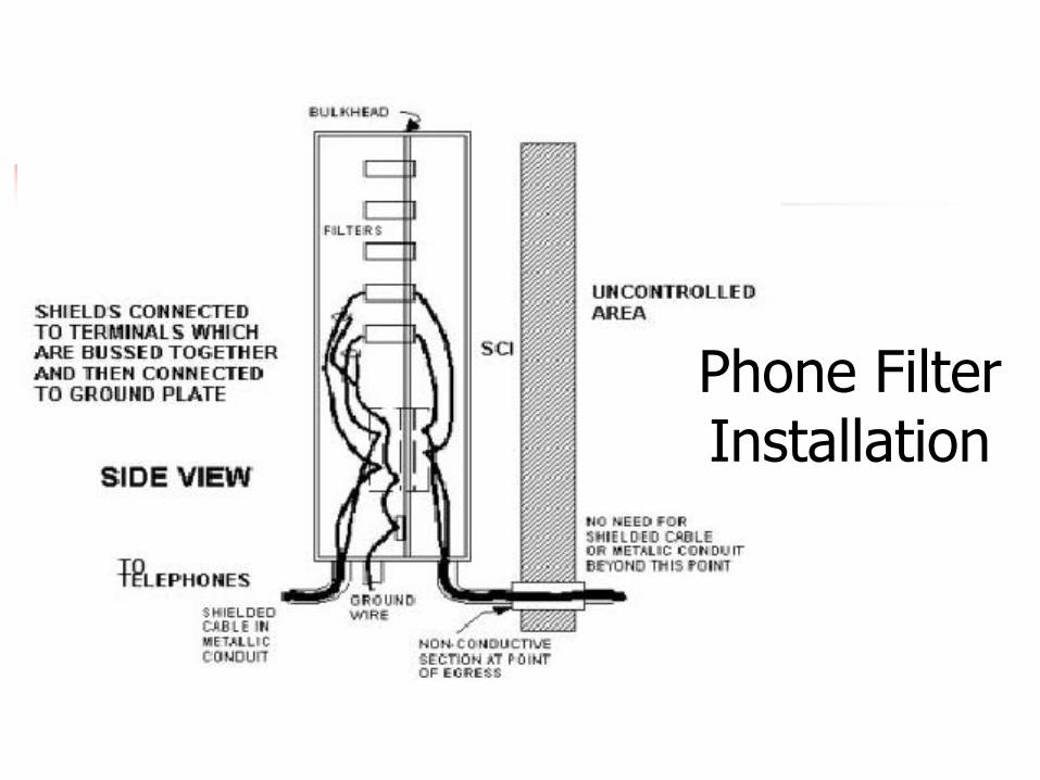
Phone Filter Installation
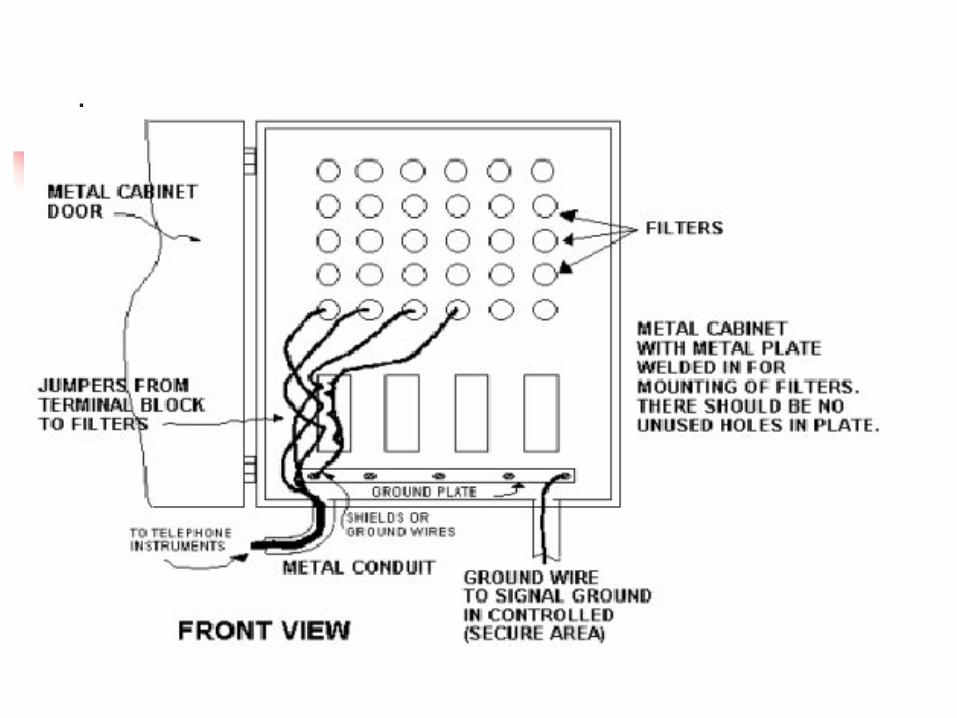
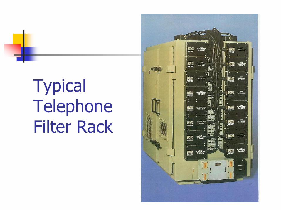
Typical Telephone Filter Rack
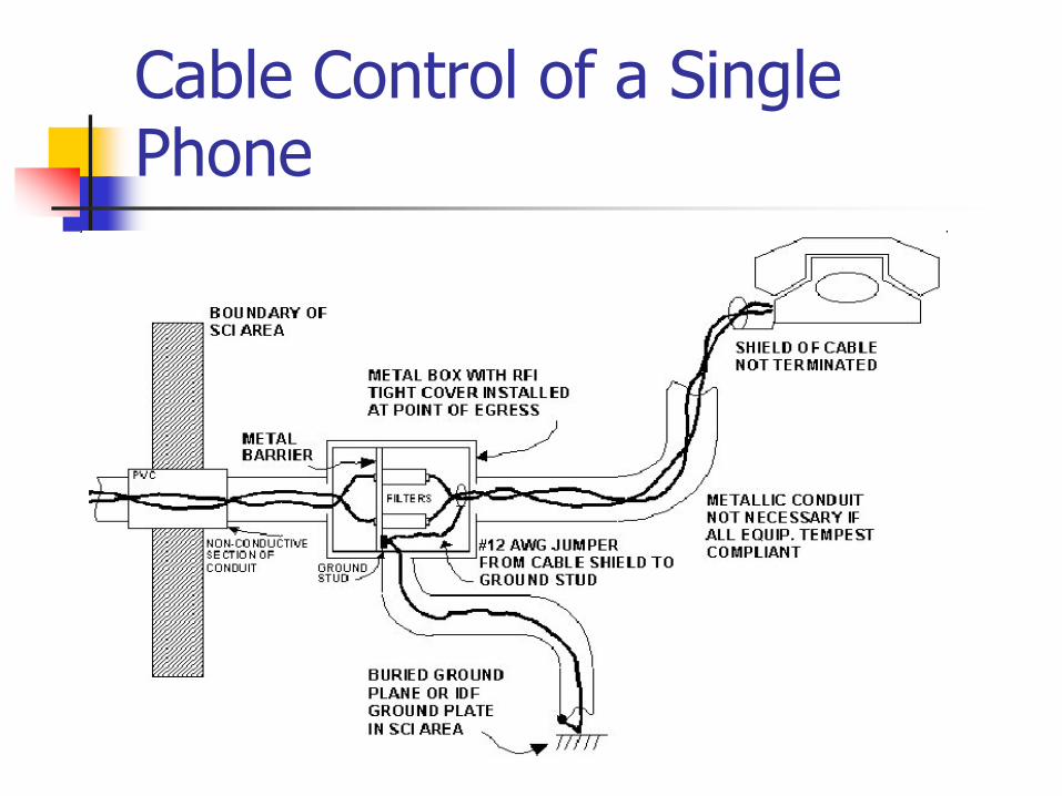
Cable Control of a Single Phone
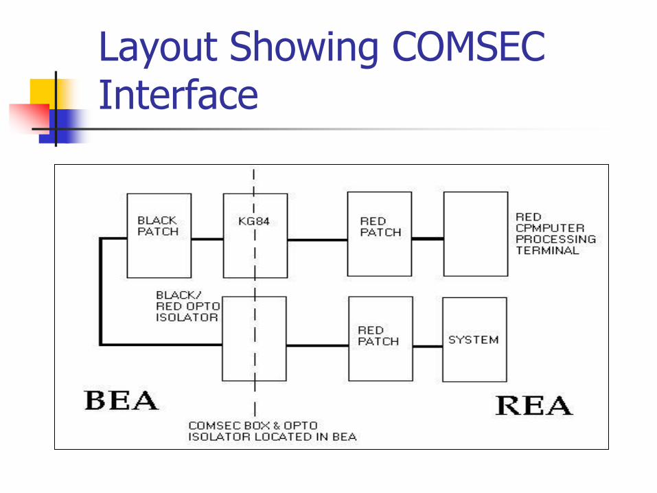
Layout Showing COMSEC Interface
Portable Shelters
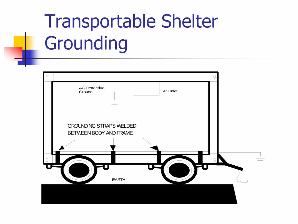
Transportable Shelter Grounding
EARTH
AC InletAC ProtectiveGround
GROUNDING STRAPS WELDED
BETWEEN BODY AND FRAME
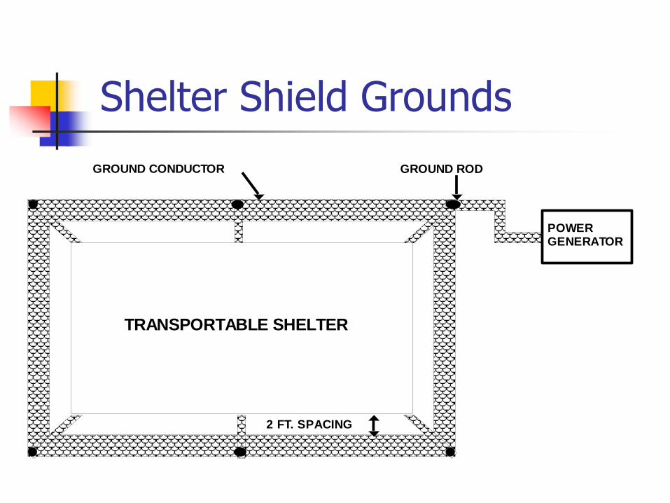
Shelter Shield Grounds
POWERGENERATOR
GROUND RODGROUND CONDUCTOR
2 FT. SPACING
TRANSPORTABLE SHELTER
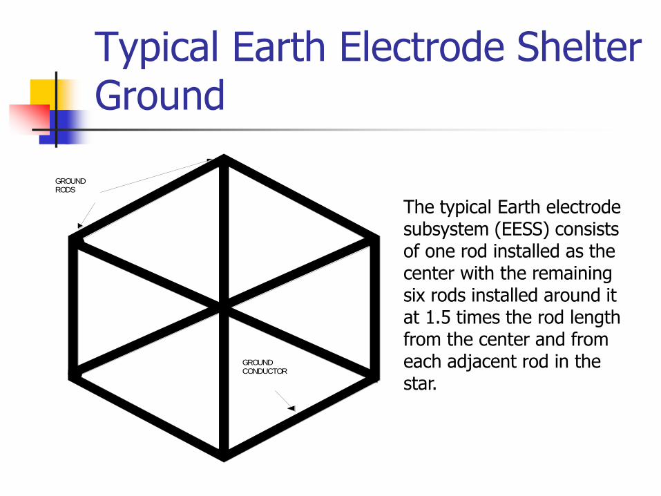
Typical Earth Electrode Shelter Ground
GROUNDRODS
GROUNDCONDUCTOR
The typical Earth electrode subsystem (EESS) consists of one rod installed as the center with the remaining six rods installed around it at 1.5 times the rod length from the center and from each adjacent rod in the star.
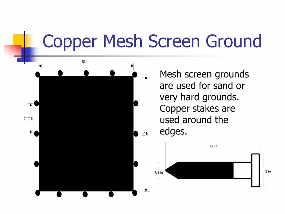
Copper Mesh Screen Ground 10 ft
10 ft
2 1/2 ft
Mesh screen grounds are used for sand or very hard grounds. Copper stakes are used around the edges.
7/8 in
12 in
2 in
Aircraft Platforms
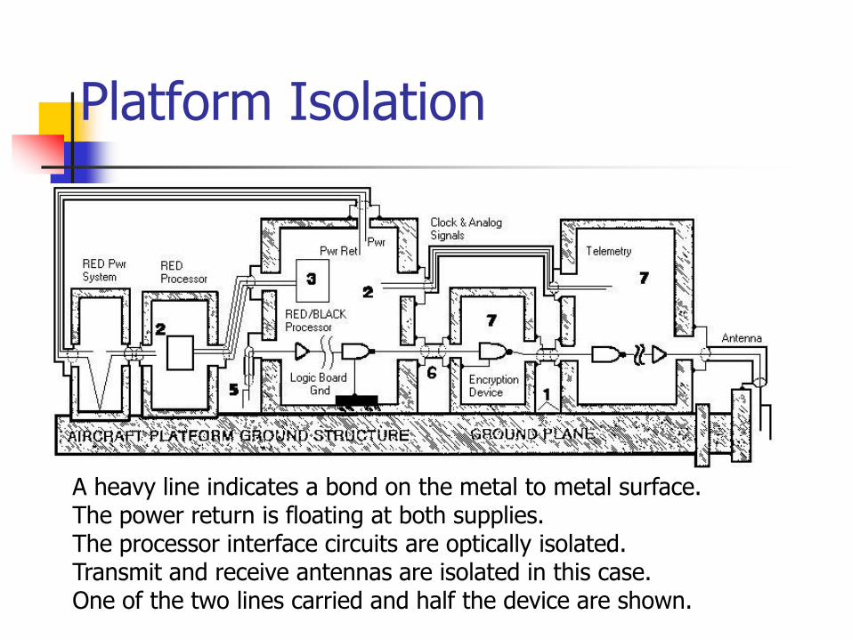
Platform Isolation
A heavy line indicates a bond on the metal to metal surface. The power return is floating at both supplies. The processor interface circuits are optically isolated. Transmit and receive antennas are isolated in this case. One of the two lines carried and half the device are shown.
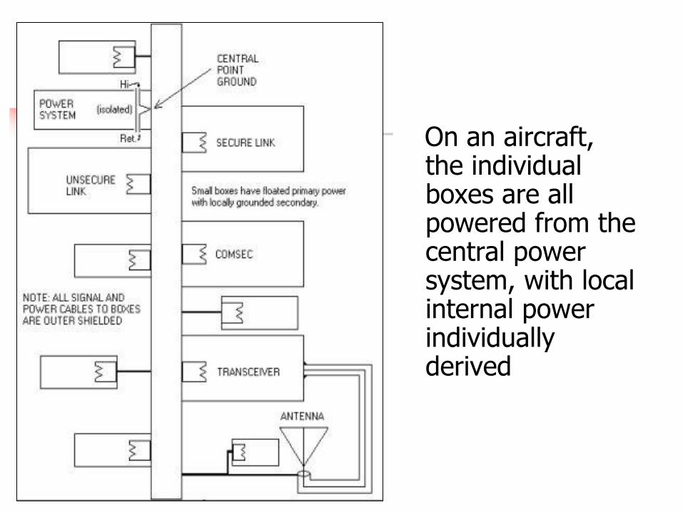
On an aircraft, the individual boxes are all powered from the central power system, with local internal power individually derived
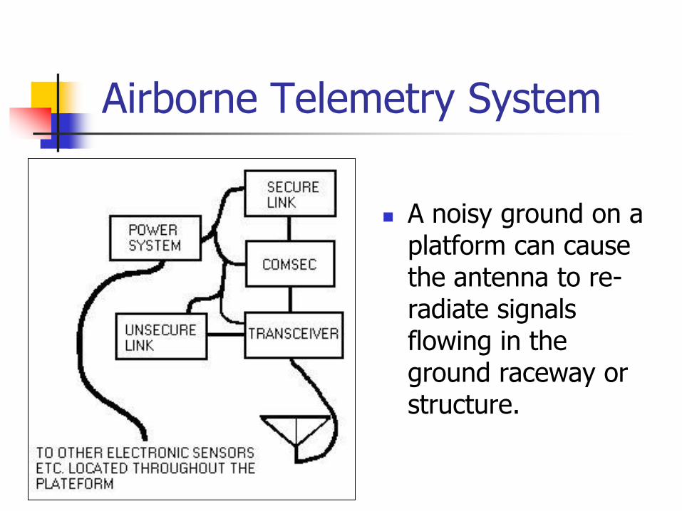
Airborne Telemetry System
A noisy ground on a platform can cause the antenna to re-radiate signals flowing in the ground raceway or structure.
Shipboard TEMPEST
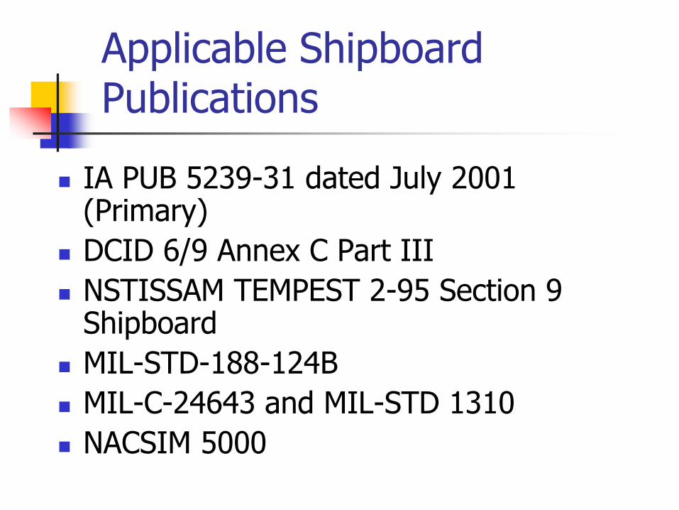
Applicable Shipboard Publications
IA PUB 5239-31 dated July 2001 (Primary)
DCID 6/9 Annex C Part III
NSTISSAM TEMPEST 2-95 Section 9 Shipboard
MIL-STD-188-124B
MIL-C-24643 and MIL-STD 1310
NACSIM 5000
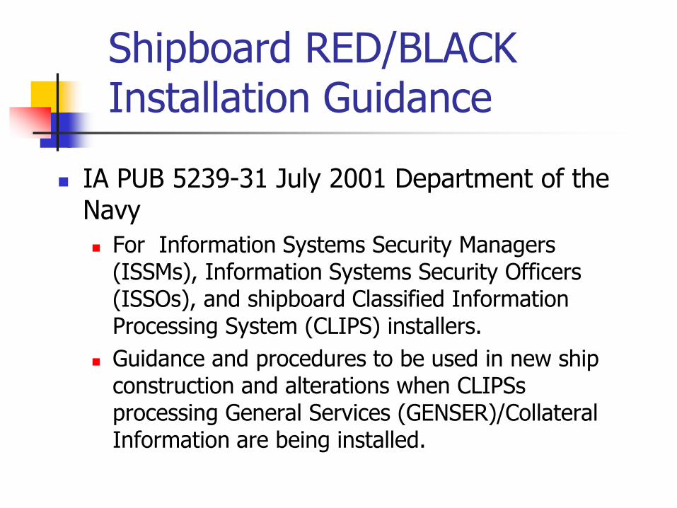
Shipboard RED/BLACK Installation Guidance
IA PUB 5239-31 July 2001 Department of the Navy
For Information Systems Security Managers (ISSMs), Information Systems Security Officers (ISSOs), and shipboard Classified Information Processing System (CLIPS) installers.
Guidance and procedures to be used in new ship construction and alterations when CLIPSs processing General Services (GENSER)/Collateral Information are being installed.
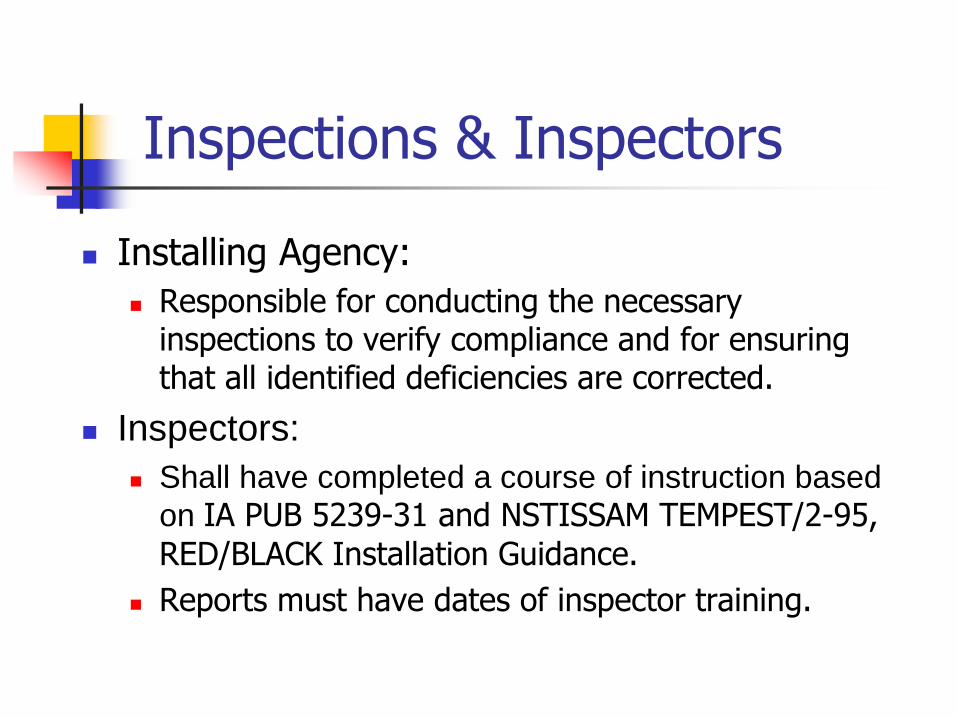
Inspections & Inspectors
Installing Agency:
Responsible for conducting the necessary inspections to verify compliance and for ensuring that all identified deficiencies are corrected.
Inspectors:
Shall have completed a course of instruction based
on IA PUB 5239-31 and NSTISSAM TEMPEST/2-95,
RED/BLACK Installation Guidance.
Reports must have dates of inspector training.
RED/BLACK Physical Separation (Ships)
A minimum of thirty-nine inches (1 meter) shall be maintained between any RED processor and:
Unshielded BLACK signal wires connected to an RF transmitter.
Unshielded BLACK power lines connected to an RF transmitter.
BLACK processing equipment having a nonmetallic enclosure with signal wire lines connected to an RF transmitter.
Transmitter Separation
RED processors shall be separated from RF transmitters by ten feet (3 meters).
Cellular telephones, cordless telephones, wireless Local Area Networks (LANs), and wireless Wide Area Networks (WANs) considered RF transmitters.
If the RF transmitter is contained in its original metallic enclosure, shielded BLACK cables are used, and a full length bonded metallic barrier exists, RED processing equipments may be installed in adjacent equipment racks or cabinets.
Common Equipment Cabinets
In surface ships, RED and BLACK processing equipment with the exception of RF transmitters may be installed in the same cabinet or rack only if:
The original metallic enclosures of both the RED and BLACK processing equipments have not been removed.
Adequate shielding has been provided between the equipment as approved by the CTTA.

Flexible Bond Straps
Flexible bond strap shall be fabricated from 1-inch flat braided wire, using lugs fabricated from 0.840-inch diameter copper tubing, flat copper stock folded over the braid or commercial copper lugs with a barrel large enough to accommodate the 1-inch braid without trimming.
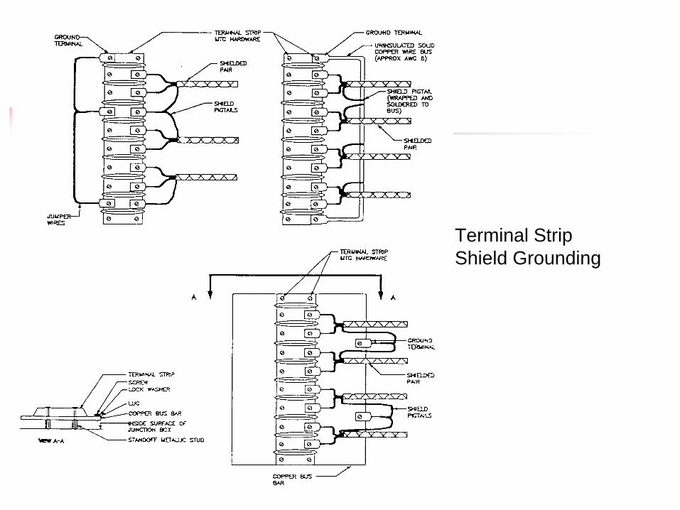
Terminal Strip
Shield Grounding
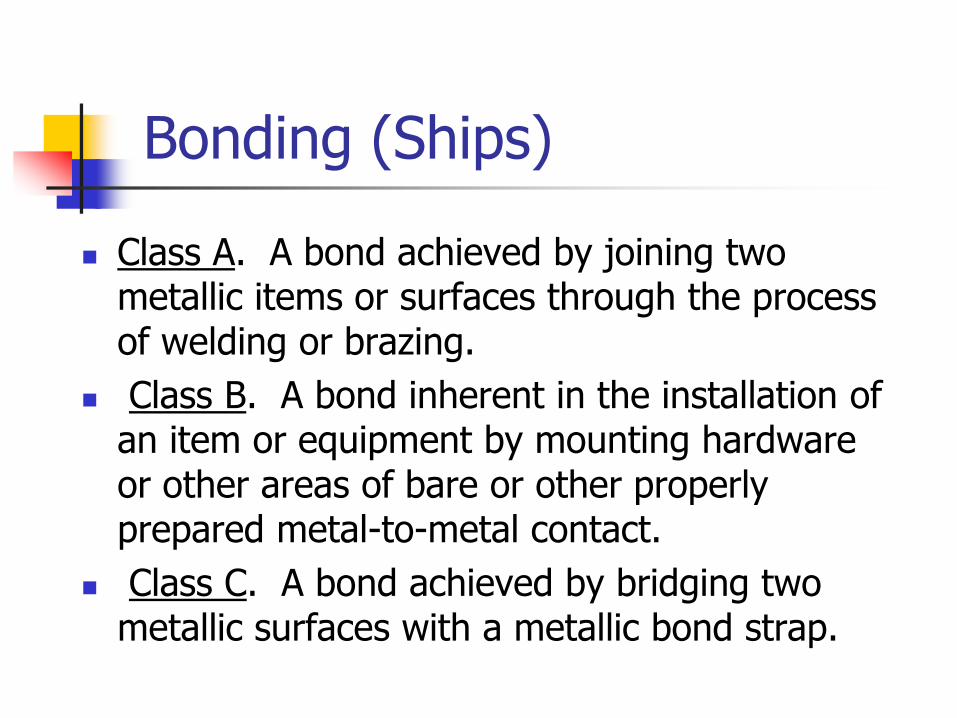
Bonding (Ships)
Class A. A bond achieved by joining two metallic items or surfaces through the process of welding or brazing.
Class B. A bond inherent in the installation of an item or equipment by mounting hardware or other areas of bare or other properly prepared metal-to-metal contact.
Class C. A bond achieved by bridging two metallic surfaces with a metallic bond strap.
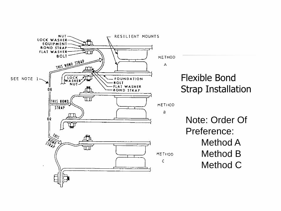
Note: Order Of
Preference:
Method A
Method B
Method C
Flexible Bond Strap Installation
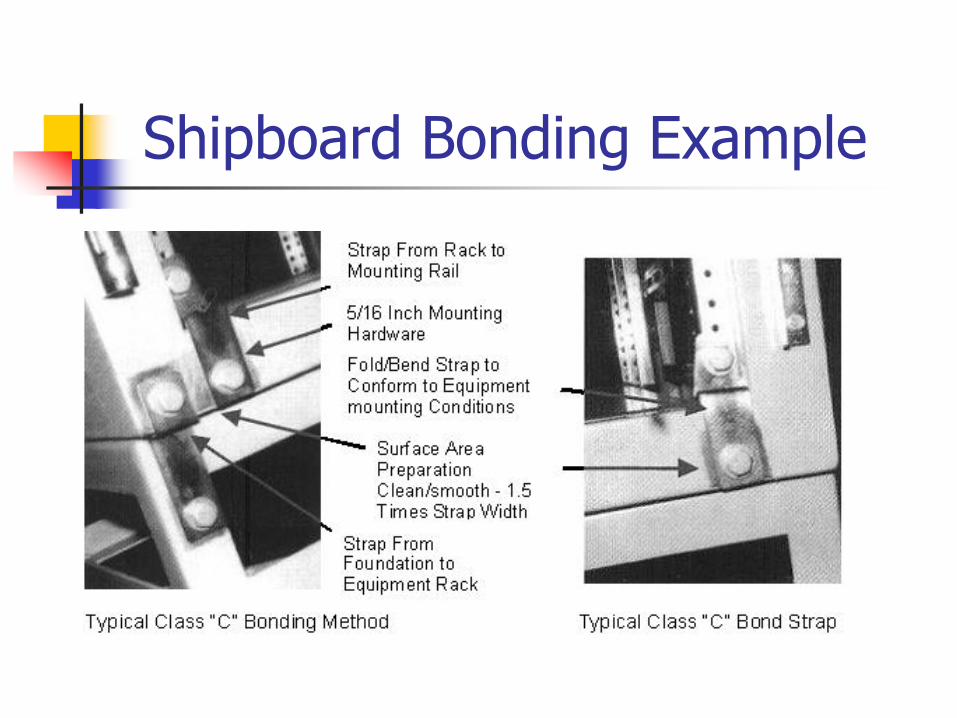
Shipboard Bonding Example
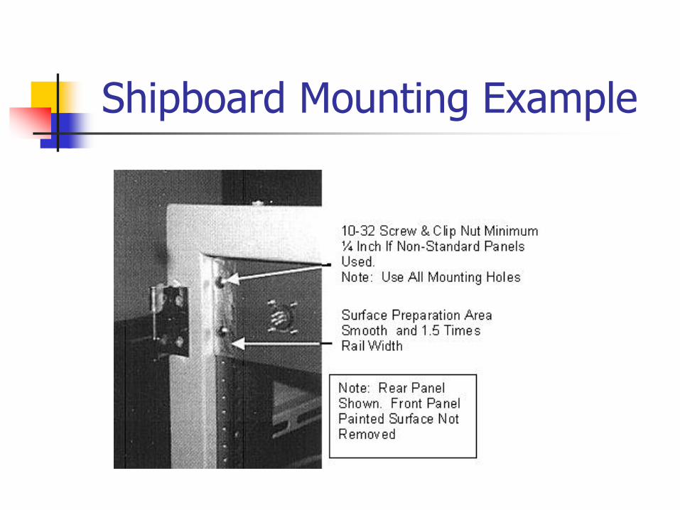
Shipboard Mounting Example