Embed Size (px)
Citation preview
Testing the Y567b/PA at f > 53 MHz
Want to test at 76 MHz and 106 MHz
• Tan wants to first test at 76 MHz, may not matter if it works at 106 MHz, since we may not even run there• But we will test at 106 MHz later. The rest of this talk is mostly about 76
MHz testing• Our calculations, following Tim Berenc’s paper, indicate that we can
modify the prototype cathode resonator• Can use a spare Booster PA power module• Need to make a new anode resonator/test cavity• First verify that we can model the existing one
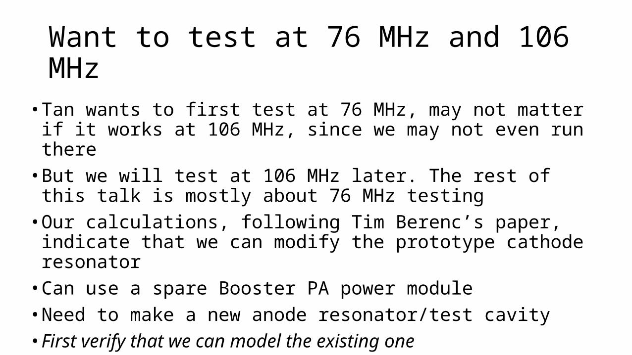
Simplified Model of Existing ~53 MHz PA
50 ohm load
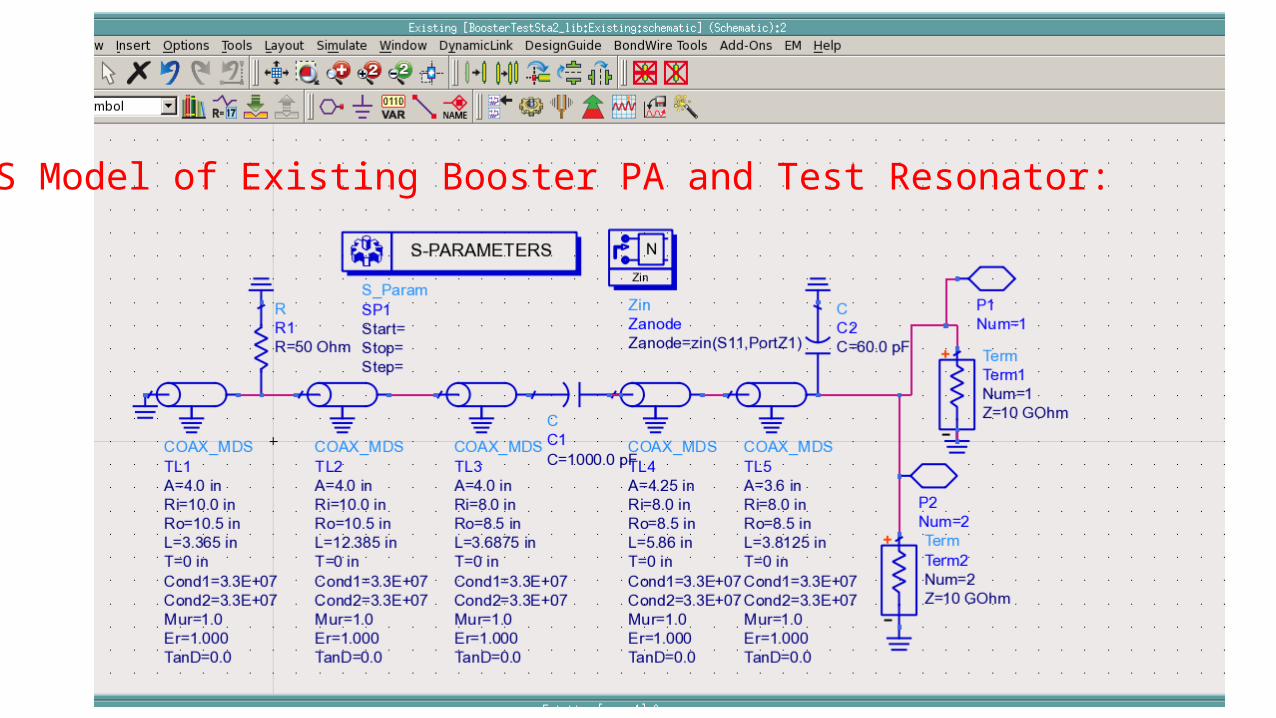
ADS Model of Existing Booster PA and Test Resonator:
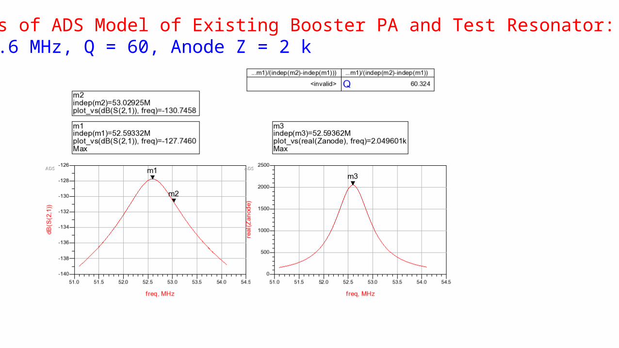
Results of ADS Model of Existing Booster PA and Test Resonator:f = 52.6 MHz, Q = 60, Anode Z = 2 k
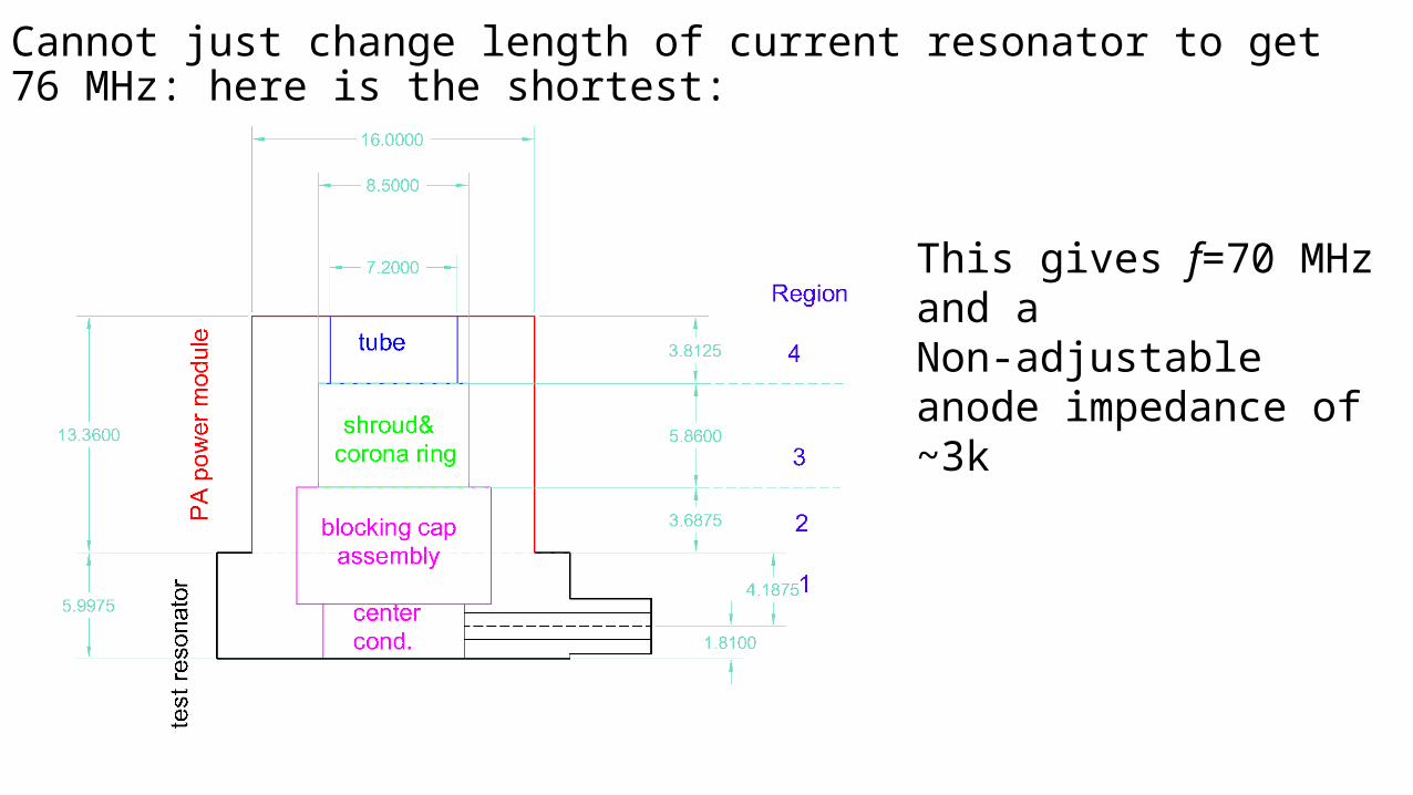
Cannot just change length of current resonator to get 76 MHz: here is the shortest:
This gives f=70 MHz and a Non-adjustable anode impedance of ~3k
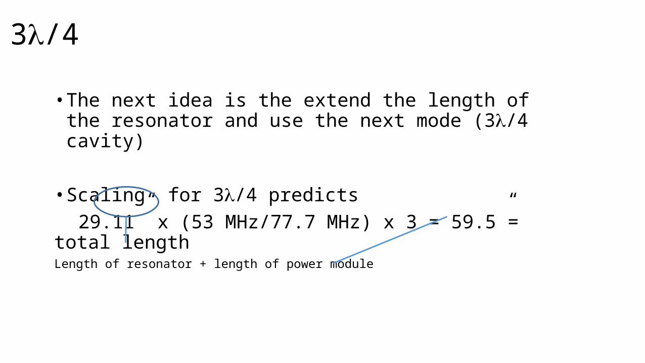
3l/4
• The next idea is the extend the length of the resonator and use the next mode (3l/4 cavity)
• Scaling for 3l/4 predicts29.11” x (53 MHz/77.7 MHz) x 3 = 59.5”= total length
Length of resonator + length of power module
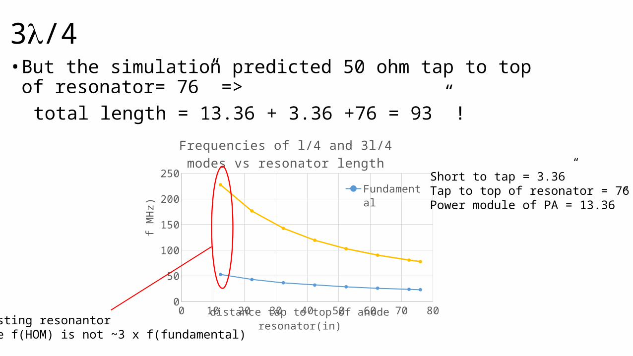
3l/4• But the simulation predicted 50 ohm tap to top of resonator= 76” =>
total length = 13.36 + 3.36 +76 = 93” !
0 10 20 30 40 50 60 70 800
50
100
150
200
250
Frequencies of l/4 and 3l/4 modes vs resonator length
FundamentalNext HOM
distance tap to top of anode resonator(in)
f MHz
)
Existing resonantorNote f(HOM) is not ~3 x f(fundamental)
Short to tap = 3.36”Tap to top of resonator = 76”Power module of PA = 13.36”
Just the HOM dependence
0 10 20 30 40 50 60 70 8075
80
85
90
95
100
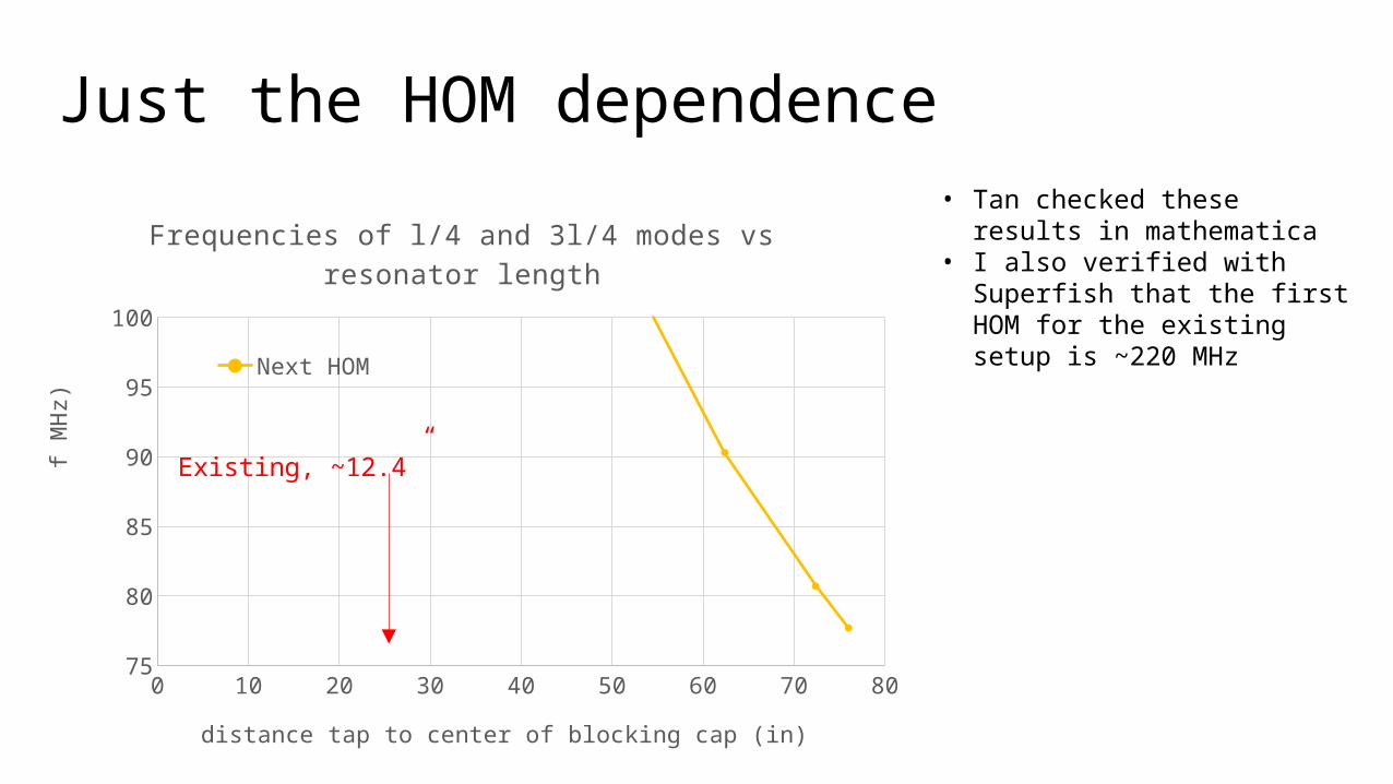
Frequencies of l/4 and 3l/4 modes vs resonator length
Next HOM
distance tap to center of blocking cap (in)
f MHz
)
Existing, ~12.4”
• Tan checked these results in mathematica
• I also verified with Superfish that the first HOM for the existing setup is ~220 MHz
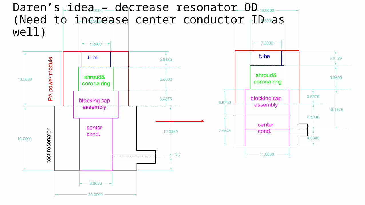
Daren’s idea – decrease resonator OD(Need to increase center conductor ID as well)
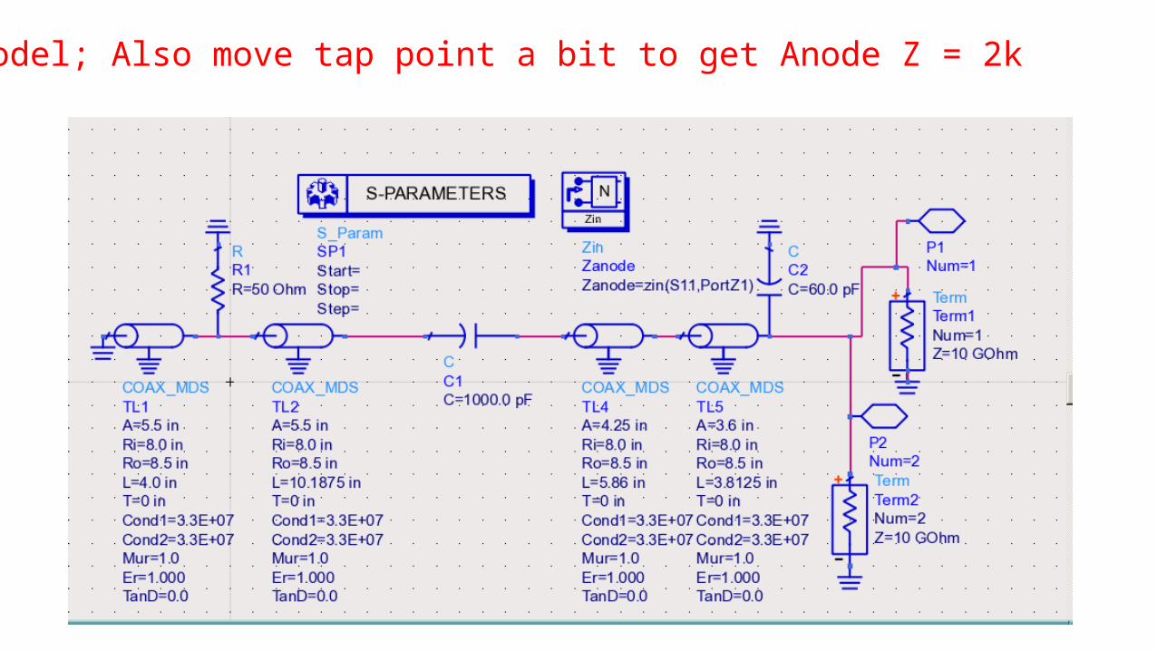
ADS Model; Also move tap point a bit to get Anode Z = 2k
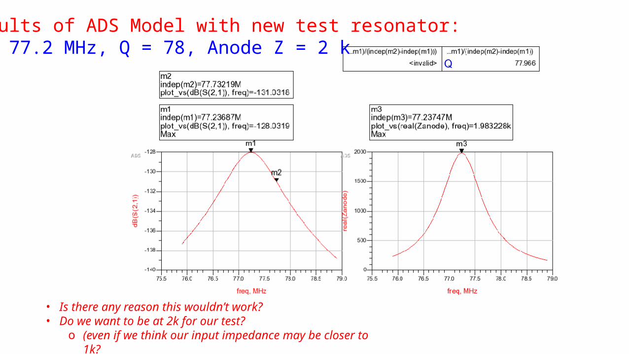
Results of ADS Model with new test resonator:f = 77.2 MHz, Q = 78, Anode Z = 2 k
• Is there any reason this wouldn’t work?• Do we want to be at 2k for our test?
o (even if we think our input impedance may be closer to 1k?
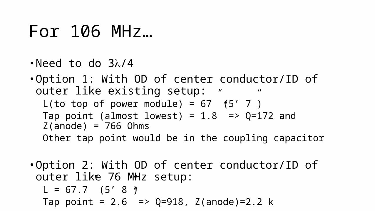
For 106 MHz…
• Need to do 3l/4• Option 1: With OD of center conductor/ID of outer like existing setup:
L(to top of power module) = 67” (5’ 7”)Tap point (almost lowest) = 1.8” => Q=172 and Z(anode) = 766 OhmsOther tap point would be in the coupling capacitor
• Option 2: With OD of center conductor/ID of outer like 76 MHz setup:L = 67.7” (5’ 8”)Tap point = 2.6” => Q=918, Z(anode)=2.2 k
Additional thoughts/questions
• If this will work, should we make the 50 ohm tap point adjustable?• Is there a mechanical engineer who usually does this type of work for
the RF group or should we use Kevin who is currently working with us on the mock cavity and second harmonic cavity?• Some ambiguity in available drawings?• Since the OD of the new resonator is the same as the power module:
Reuse old power module shell for outer conductor of new anode resonator? (again Daren’s idea - because of the flange, see next page)
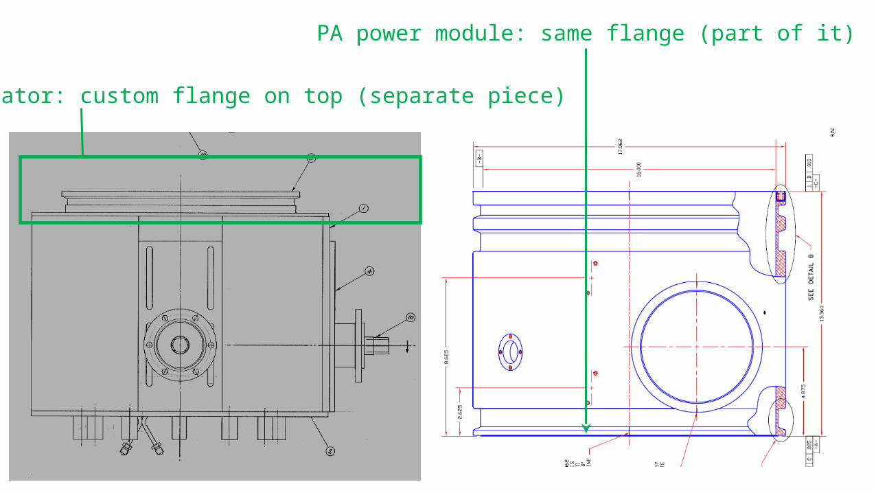
Resonator: custom flange on top (separate piece)
PA power module: same flange (part of it)
Pros/Cons
• If we reuse and old part we don’t have to worry about the flange• (Also, since the OD of the resonator is now smaller and the same OD
as the power module, the same design for a separate part flange cannot be used because there would be no place for the screws)• If we reuse we may have to block the big hole?
Drawings used• For tube, shroud, corona ring, and PA power module outer shell:RF.bd/Common/High_Level/Booster/PA/Booster PA pdf Prints
• For test resonator: from EE support Drawing Information Database 63170(assembly) and referenced drawings
• For blocking cap assembly: 5037 “Booster Accelerator RF System Accelerating Cavity Power Ampl and Anode Blocking Capactor Layout (1971) • (which links to the wrong drawing in the database, had to get from the drawer
• But 62906 from 1972 contains more dimensions (but less info in other ways) compared to 5037• Ultimately, I think we just need to know the OD and hole positions of the blocking cap
assembly


![PVCPR11 Edital 3.5 GHz v03.ppt [Modo de Compatibilidade]...2011/06/09 · 35 MHz 35 MHz 10 MHz 10 MHz 10 MHz 10 MHz 10 MHz 10 MHz 3.400,00 MHz 3.600,00 MHz 10 MHz 35 MHz 10 MHz 10](https://img.pdfslide.net/doc/110x75/5f7286506e7f433bb4685297/pvcpr11-edital-35-ghz-v03ppt-modo-de-compatibilidade-20110609-35-mhz.jpg)