Embed Size (px)
Citation preview
Nuclear Physics B (Proc. Suppl.) 127 (2004) E3-E7 SUPPLEMENTS www.elsevierphysics.com
The ATLAS Trigger and Data Acquisition System During the 2002 Combined Testbeam Run *
G. Lehmanna on behalf of the ATLAS MDT, Pixel, Tile Calorimeter and TDAQ Teams
aCERN, Geneva, Switzerland
The Trigger and Data Acquisition System of the ATLAS experiment at CERN has undergone a series of design and prototyping phases, with the aim of studying different architectural and technological choices suited to sustaining the very high event rate and data size of this experiment: up to 100 kHz Level 1 trigger accept rate, with events of the order of 2 MB.
The DAQIEF-1 project, a vertical slice of the Data AcQuisition and Event Filter, is one of these prototypes. After the completion of its development and implementation, this prototype was reengineered for exploitation as a DAQ system for the ATLAS detectors in testing and calibration phase. During summer 2002 DAQ/EF-1 has been successfully integrated with several detectors.
This paper presents an overview of DAQ/EF-1, the implementation of a PC based setup that has been prepared for the combined testbeam of the Pixel, the tile calorimeter and the MDT detectors, and the usage of the Event Filter during data taking.
1. INTRODUCTION
T he ATLAS experiment [l] at the Large Hadron
Collider (LHC) is scheduled to start taking data in 2007. Its main goals are the comprehension of the Electra-weak symmetry breaking mechanism and the discovery of new physics signatures beyond the ones predicted by the Standard Model. The high bunch crossing frequency of the LHC (40 MHz) as well as the large amount of data produced by ATLAS (-2MB formatted per event) requires the design of a performant Data AcQuisition (DAQ) system with three trigger levels. The first trigger level will carry out a rate reduction from 40 MHz down to at most 100 kHz. The second level trigger will reduce the rate by another two orders of magnitude, and the Event Filter (EF) will bring down the data-recording rate to 100 Hz approximately.
The DAQ/EF prototype-l [2] is a vertical slice of the DAQ and EF systems, which spans from the detector output to mass storage. It includes all the hardware and software elements of the data flow, its control and monitoring, as well as all the elements of a complete online system. The DAQ/EF-1 data flow starts at the receiving side of the Readout Link
(ROL), which connects the DAQ to the detector specific electronics, the Readout Drivers (ROD). The communication protocol chosen in ATLAS for the ROL is S-LINK [3], a simple FIFO-like data link with flow-control.
2. DAQ/EF-1 DECOMPOSITION In order to allow for an efficient and parallel
development of the different aspects of the prototype, the DAQ/EF-1 was subdivided in three main systems with clear interfaces: the DataFlow, the Event Filter and the Online software.
2.1, The DataFlow The DataFlow system is responsible for the
movement of event data from the ROL to the EF and from the EF to mass storage. It furthermore provides samples of event data for monitoring purposes and implements local control for the various DataFlow elements.
2.2. The Event Filter The EF forms the last trigger level of the ATLAS
experiment. It reconstructs and analyzes the complete events using Offline algorithms. The EF will also carry out alignment and calibration procedures and monitoring.
* DOI of original article 10.1016/SO920-5632(03)02260-6.
0920-56321% - see front matter 0 2004 Elsevier B.V. All rights reserved. doi:10.1016/j.nuclphysbps.2003.12.043
E4 G. LehmandNuclear Physics B (proc. Suppl.) 127 (2004) E3-E7
2.3. The Online Software The Online software encompasses the software
needed to configure, control and monitor the DAQ, but excludes the transportation and processing of physics data. It interfaces the DAQ system to the end user.
In the following sections we will concentrate on the DataFlow and EF aspects of the DAQ/EF prototypel. A description of the Online Software system can be found in [2].
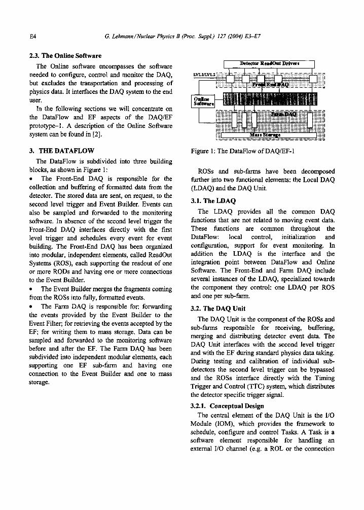
3. THE DATAFLOW The DataFlow is subdivided into three building
blocks, as shown in Figure 1: l The Front-End DAQ is responsible for the collection and buffering of formatted data from the detector. The stored data are sent, on request, to the second level trigger and Event Builder. Events can also be sampled and forwarded to the monitoring software. In absence of the second level trigger the Front-End DAQ interfaces directly with the first level trigger and schedules every event for event building. The Front-End DAQ has been organized into modular, independent elements, called Readout Systems (ROS), each supporting the readout of one or more RODS and having one or more connections to the Event Builder. l The Event Builder merges the fragments coming from the ROSS into fully, formatted events. l The Farm DAQ is responsible for: forwarding the events provided by the Event Builder to the Event Filter; for retrieving the events accepted by the EF; for writing them to mass storage. Data can be sampled and forwarded to the monitoring software before and after the EF. The Farm DAQ has been subdivided into independent modular elements, each supporting one EF sub-farm and having one connection to the Event Builder and one to mass storage.
Figure 1: The DataFlow of DAQ/EF- 1
ROSS and sub-farms have been decomposed further into two functional elements: the Local DAQ (LDAQ) and the DAQ Unit.
3.1. The LDAQ The LDAQ provides all the common DAQ
functions that are not related to moving event data. These functions are common throughout the DataFlow: local control, initialization and configuration, support for event monitoring. In addition the LDAQ is the interface and the integration point between DataFlow and Online Software. The Front-End and Farm DAQ include several instances of the LDAQ, specialized towards the component they control: one LDAQ per ROS and one per sub-farm.
3.2. The DAQ Unit The DAQ Unit is the component of the ROSS and
sub-farms responsible for receiving, buffering, merging and distributing detector event data. The DAQ Unit interfaces with the second level trigger and with the EF during standard physics data taking. During testing and calibration of individual sub- detectors the second level trigger can be bypassed and the ROSS interface directly with the Timing Trigger and Control (TTC) system, which distributes the detector specific trigger signal.
3.2.1. Conceptual Design The central element of the DAQ Unit is the I/O
Module (IOM), which provides the framework to schedule, configure and control Tasks. A Task is a software element responsible for handling an external I/O channel (e.g. a ROL or the connection
G. LehmandNuclear Physics B (Pnx. Suppl.) 127 (2004) E3-E7 E5
to the Event Builder). An IOM can control several Tasks, and the DAQ Unit can be composed by one or more IOMs. The message passing system used for communication among Tasks hides their location within the same or in different IOMs.
3.2.2. Software Design and Implementation Design of the DAQ Unit software has been based
on layering and encapsulation: all hardware and operating system dependent software packages have been isolated from the rest. An example of this paradigm is the message passing library, which supports communication between Tasks over VMEbus, PCI, PVIC [4], TCPAP and system memory via the same API.
Thanks to this software design it was possible to port applications developed initially for the LynxOS operating system to Linux without major changes.
Despite functionality rather than performance being the main goal of DAQ/EF-1, some optimization was carried out during the implementation of the DAQ Unit software. In particular, the IOMs are single threaded processes; interrupts and device drivers are not used in order to avoid associated overheads, and minimum operating system functionality is used during run time.
3.2.3. The VMEbus Based Implementation The first implementation of the DAQ Unit was
based on single board computers (SBC), from CES [5] and Motorola [6], running the LynxOS operating system and interconnected via VMEbus (and, optionally, PVIC).
In this implementation every SBC in a ROS runs a single IOM, which is handling one I/O channel external to the ROS. There are at least three instances of an IOM: one or more Readout Buffers (ROB), each handling one ROL; the TRiGger IOM (TRG), connected to the external trigger system; the Event Builder InterFace (EBIF), which collects and provides event fragments to the Event Builder. The number of ROLs dealt with by a single ROB can be increased with the introduction of so called ROBINS, PC1 mezzanine cards with onboard processing power, which can handle one or more ROLs each. At the level of the sub-farm there are two IOMs: the SubFarm Input (SFI) receives the events from the Event Builder and forwards them to the EF and the
SubFarm Output (SFO) receives the events from the EF and sends them to mass storage.
Tasks in different IOMs communicate among each other via VMEbus and optionally PVIC. An additional SBC provides the LDAQ functionality and the VMEbus is used also for configuration, control, error reporting and monitoring.
The main advantage of this implementation is that I/O channels are treated concurrently and independently. This is particularly important when the DataFlow is integrated with the second level trigger, which rejects a big fraction of the events. The second level trigger completely changes the frequency of scheduling of the Tasks within the ROS. In particular, while the ROBS have to be capable of receiving data at a rate of up to 100 kHz, the EBIF is scheduled at a frequency of a few kHz. As a consequence the Tasks residing in the ROBS have to be highly performant, while the requirements in terms of CPU utilization on the Tasks running in the EBIF can be relaxed. Another advantage of a crate based ROS is that the number of ports required for the Event Builder can be reduced by increasing the number of ROBS per ROS. The multiplexing of ROLs into a single Event Builder output depends on the bandwidth of the bus connecting each ROB to the ROBINS, on the bandwidth of the bus over which data from the ROBS have to be collected into an EBIF and on the Event Builder link speed.
This implementation has given the possibility to study all issues related to a deployment of the DAQ Unit in VMEbus and can be used to investigate the performance of new VMEbus standards or of other crate based technologies.
3.2.4. The PC Based Implementation The Tasks developed within the ROS DAQ Unit
during the VMEbus based implementation have been regrouped within the IOM framework to provide the full functionality of the ROS DAQ Unit in a single IOM. Contrary to the VMEbus based ROS, an example of a multi process and multiprocessor implementation, the PC based ROS implements all Tasks in one single-threaded process. The Tasks communicate via system memory and the LDAQ functionality is implemented as a different process sharing the CPU with the IOM. At the sub-farm level
G. Lehmann/Nuclear Physics B (Pnx. Suppl.) 127 (2004) E3-E7 E7
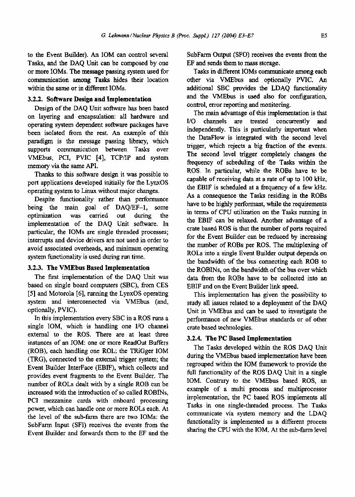
5.3. The EF as Monitoring and Analysis Tool The EF was not used for data reduction purposes
during testbeam. The PTs were configured to run sohare specifically developed by the detector experts in order to monitor the beam profile, reconstruct particle tracks, calculate the energy of the particles and produce n-tuples for offline data analysis. An example of the results obtained with these programs can be seen in Figure 3: here, the reconstruction of the energy deposited in the Tile calorimeter allows to identify the particles composing the beam.
Multi particles
jJ!ldiJ 0 2013 400 6m em
Figure 3: Particle identification as provided by the EF using the Tile calorimeter data.
5.4. Prototype1 evaluation Functional features and performance delivered by
DAQ/EF-1 were more than adequate for the purpose of testing and calibrating detectors. None of the readout channels was capable of saturating the DAQ system and no &ad time was introduced due to the DataFlow. The introduction of the Event Filter for calibration and data pre-processing was greatly appreciated by testbeam users.
Despite the fact that the design and implementation of the DAQIEF prototype-l were tailored towards the requirements of final ATLAS system, its modularity and flexibility have allowed us to also use it for small experimental setups, such as the testbeams of the ATLAS detectors.
For the Tile calorimeter, Pixel and Muon detectors testbeams a complete DataFlow chain has been setup. The Event Filter has been used during data taking for running calibration processes and produce n-tuples for further offline analysis
The DAQ/EF-1 has accomplished the task of being a prototype for the development of the functionality needed by the ATLAS DAQ and EF systems and the evaluation of technologies suited to the achievement of the required performance. It is now a mature product, which is being used as a DAQ system during the testing and calibration of the ATLAS detectors.
7. REFERENCES
111
PI
(31 141
r51
PI
[71
ATLAS Collaboration, “Technical Proposal for a General-Purpose pp Experiment at the Large Hadron Collider at CERN”, CERN/LHCC/94- 43,1994 ATLAS Collaboration, “ATLAS High-Level Triggers, DAQ and DCS Technical Proposal”, Chapter 5, CERN/LHCC/2000-17, 3 1 March 2000 http://hsi.web.cem.ch/HIS/s-link PC1 Vertical Interconnect (PVIC), product catalogue, Creative Electronics Systems, Geneva, Switzerland The RIO2 806x, product catalogue, Creative Electronics Systems, Geneva, Switzerland MOTOROLA-MVME2000, http:llwww.mcg.mot.com http://hsi.web.cem.ch/HSI/s-link/products.html
6. SUMMARY
We have presented the general concept of. the DAQ/EF prototype-l, emphasizing the design of the DataFlow, and, in particular, of the DAQ Unit.