Embed Size (px)
Citation preview
The Chernobyl Nuclear Power Plant accident : its decommissioning, the Interim Spent Fuel Storage ISF-2, the nuclear waste treatment plants and the Safe Confinement project.
by Dr. Ing. Fulcieri Maltini Ph.D. SMIEEE, life, PES, Comsoc FM Consultants Associates, France
KeywordsNuclear power, Disaster engineering, Decommissioning, Waste management & disposal, Buildings, structures & design.
Abstract
On April 26, 1986, the Unit 4 of the RBMK nuclear power plant of Chernobyl, in Ukraine, went out of control during a test at low-power, leading to an explosion and fire. The reactor building was totally demolished and very large amounts of radiation were released into the atmosphere for several hundred miles around the site including the nearby town of Pripyat. The explosion leaving tons of nuclear waste and spent fuel residues without any protection and control. Several square kilometres were totally contaminated. Several hundred thousand people were affected by the radiation fall out. The radioactive cloud spread across Europe affecting most of the northern, eastern, central and southern Europe.
The initiative of the G7 countries to launch an important programme for the closure of some Soviet built nuclear plants was accepted by several countries. A team of engineers was established within the European Bank for Reconstruction and Development were a fund was provided by the donor countries for the entire design, management of all projects and the plants decommissioning.
The Chernobyl programme includes the establishment of a safety strategy for the entire site remediation and the planning for the plant decommissioning. Several facilities that will process and store the spent fuel and the radioactive liquid and solid waste as well as to protect the plant damaged structures have been designed and are under construction.
The author has been responsible for the programme with the EBRD Nuclear Safety Account team. This paper describes the design and construction of a new interim spent fuel storage, the liquid and solid radioactive treatment plants and the construction of a unique and very large New Safe Confinement that, when completed, will be moved over of the reactor Unit 4.
1. Introduction
In 1993 following the 26 April 1986 Chernobyl accident, the G7 launched an initiative on the prevention of nuclear accidents within Russian built plants and agreed that the EBRD - European Bank for Reconstruction and Development, establishes a fund aimed at the closure and decommissioning of some Russian built Nuclear Power plants of the RBMK and VVER 440-230 type. The initiative included initially the plants of Ignalina units 1 and 2 in Lithuania, Kozloduy units 1, 2, 3 and 4 in Bulgaria, Saint Petersburg units 1, 2, 3, and 4 in the Russian Federation. In 1996, Chernobyl three remaining units in Ukraine were added to the scope. The fund contributors included the G7 countries, the EU, Belgium, Denmark, Finland, the Netherlands, Norway, Sweden and Switzerland. Initial contributions were in excess of € 285 million. As of today 40 countries and the European Community are contributing with grants for the safety upgrades and the decommissioning of the above nuclear power plants. The concept, that had been accepted by the plants countries, included for each plant a nuclear safety assessment, the construction of an essential number of short terms safety improvements facilities and the final closure of the plant. Later an additional special fund was established for the decommissioning of each plant.
2
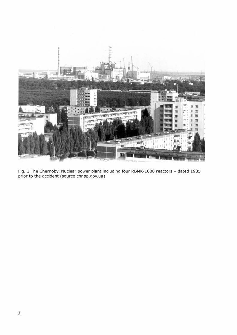
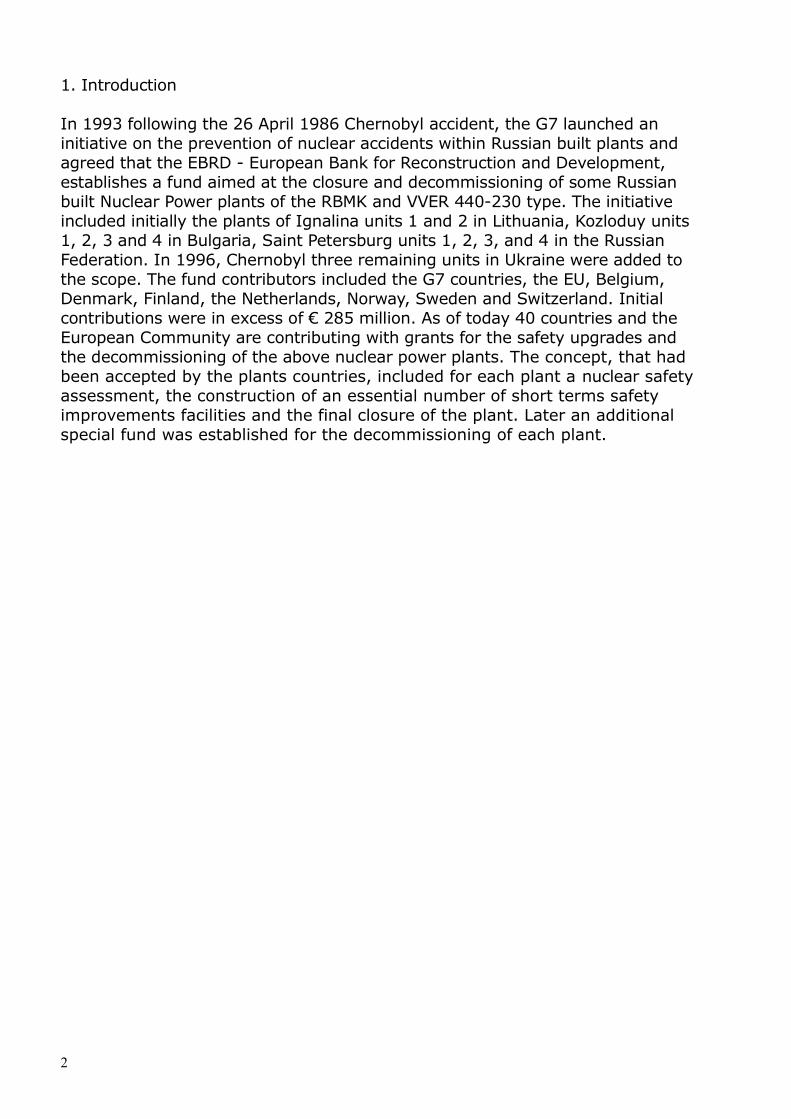
Fig. 1 The Chernobyl Nuclear power plant including four RBMK-1000 reactors – dated 1985 prior to the accident (source chnpp.gov.ua)
3
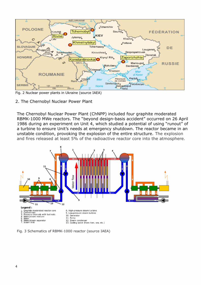
Fig. 2 Nuclear power plants in Ukraine (source IAEA)
2. The Chernobyl Nuclear Power Plant
The Chernobyl Nuclear Power Plant (ChNPP) included four graphite moderated RBMK-1000 MWe reactors. The “beyond design-basis accident” occurred on 26 April 1986 during an experiment on Unit 4, which studied a potential of using “runout” of a turbine to ensure Unit’s needs at emergency shutdown. The reactor became in an unstable condition, provoking the explosion of the entire structure. The explosion and fires released at least 5% of the radioactive reactor core into the atmosphere.
Fig. 3 Schematics of RBMK-1000 reactor (source IAEA)
4
Fig. 4 The Chernobyl NPP Unit 4 after the accident (source chnpp.gov.ua)
Unit 4 was destroyed and the radiation levels in some areas of the reactor building have been estimated to be 0,056 sieverts per second (Sv/s) (1.4 mA/Kg), equivalent to more than 200 sieverts per hour (Sv/hr). A lethal dose is around 5 sieverts over 5 hours, so in some areas, unprotected workers received fatal doses in less than a minute. A dosimeter capable of measuring up to 10 Sv/s (0.3 A/kg) was buried in the rubble of a collapsed part of the building.All remaining dosimeters had limits of 10 exp-5 sv/s (0.3 µA/kg) and therefore read "off scale". The reactor crew could ascertain only that the radiation levels were somewhere above 10 exp-5 sv/s (0,0036 sv/h, or 0.3 µA/kg), while the true levels were much higher in some areas.
During the accident and the following days a significant cloud containing mostly Caesium, Strontium and other fission products, including Plutonium, spread across Ukraine, northern, eastern, central and southern Europe. Fig. 5 shows a representation of the radioactive cloud eight days after the accident.
5
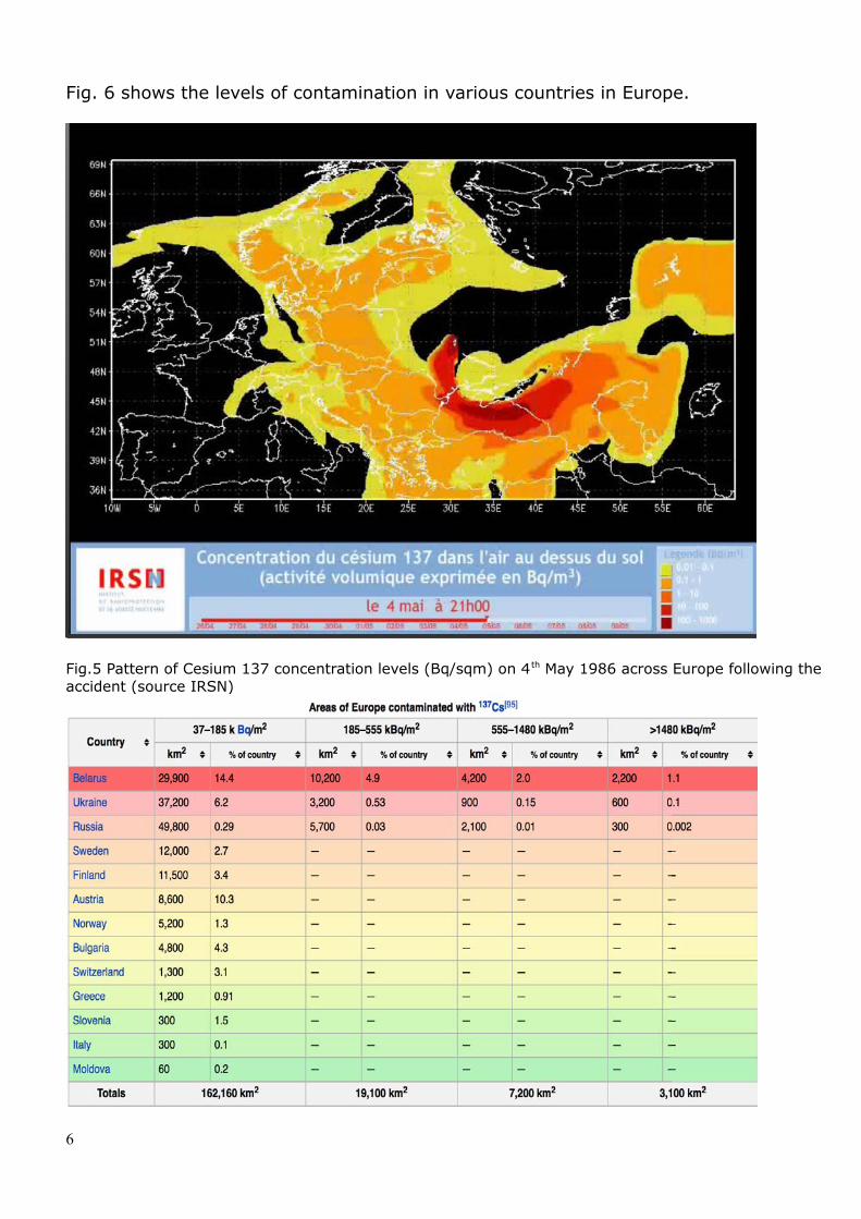
Fig. 6 shows the levels of contamination in various countries in Europe.
Fig.5 Pattern of Cesium 137 concentration levels (Bq/sqm) on 4th May 1986 across Europe following the accident (source IRSN)
6

Fig. 6 Radiation levels across Ukraine and Europe following accident. (source WHO/IAEA)
The French government strongly denied that the radioactive cloud had “entered” the country territory. However, as shown in Fig 7 it was obliged later to admit that large part of east and southern land was contaminated by Cesium 137.
7
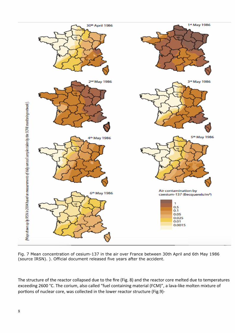
Fig. 7 Mean concentration of cesium-137 in the air over France between 30th April and 6th May 1986 (source IRSN). ). Official document released five years after the accident.
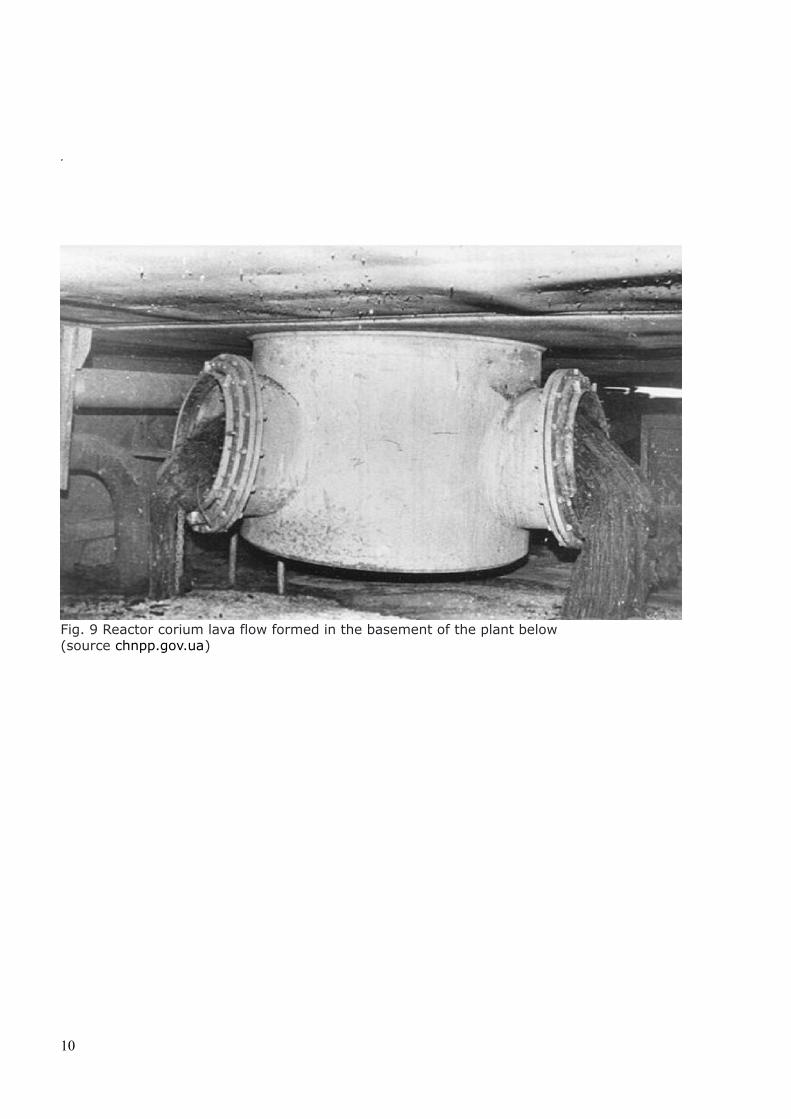
The structure of the reactor collapsed due to the fire (Fig. 8) and the reactor core melted due to temperatures exceeding 2600 °C. The corium, also called “fuel containing material (FCM)”, a lava-like molten mixture of portions of nuclear core, was collected in the lower reactor structure (Fig.9)-
8
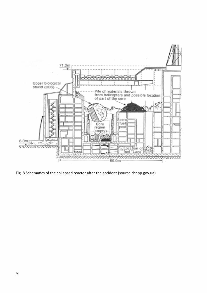
Fig. 8 Schematics of the collapsed reactor after the accident (source chnpp.gov.ua)
9
.
Fig. 9 Reactor corium lava flow formed in the basement of the plant below (source chnpp.gov.ua)
10
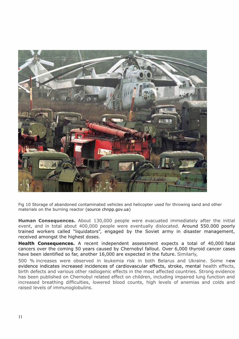
Fig 10 Storage of abandoned contaminated vehicles and helicopter used for throwing sand and other materials on the burning reactor (source chnpp.gov.ua)
Human Consequences. About 130,000 people were evacuated immediately after the initialevent, and in total about 400,000 people were eventually dislocated. Around 550.000 poorlytrained workers called “liquidators”, engaged by the Soviet army in disaster management,received amongst the highest doses.Health Consequences. A recent independent assessment expects a total of 40,000 fatalcancers over the coming 50 years caused by Chernobyl fallout. Over 6,000 thyroid cancer caseshave been identified so far, another 16,000 are expected in the future. Similarly, 500 % increases were observed in leukemia risk in both Belarus and Ukraine. Some newevidence indicates increased incidences of cardiovascular effects, stroke, mental health effects,birth defects and various other radiogenic effects in the most affected countries. Strong evidencehas been published on Chernobyl related effect on children, including impaired lung function andincreased breathing difficulties, lowered blood counts, high levels of anemias and colds andraised levels of immunoglobulins.
11
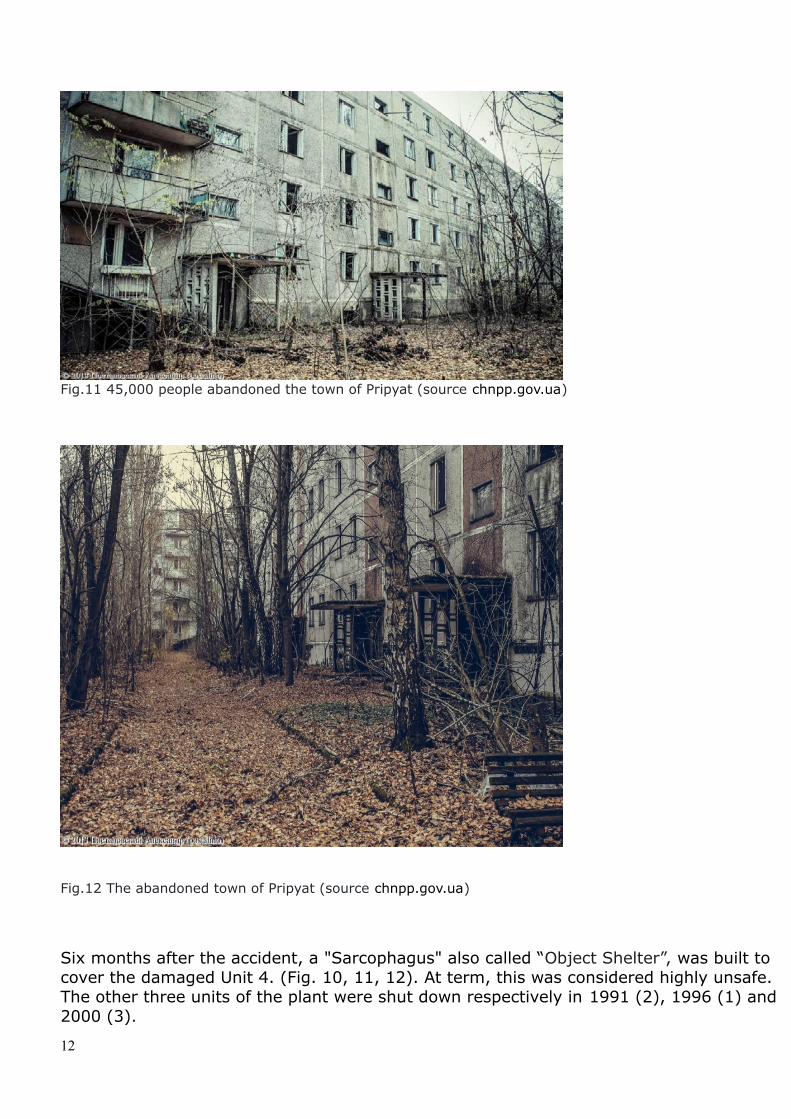
Fig.11 45,000 people abandoned the town of Pripyat (source chnpp.gov.ua)
Fig.12 The abandoned town of Pripyat (source chnpp.gov.ua)
Six months after the accident, a "Sarcophagus" also called “Object Shelter”, was built to cover the damaged Unit 4. (Fig. 10, 11, 12). At term, this was considered highly unsafe. The other three units of the plant were shut down respectively in 1991 (2), 1996 (1) and 2000 (3).
12
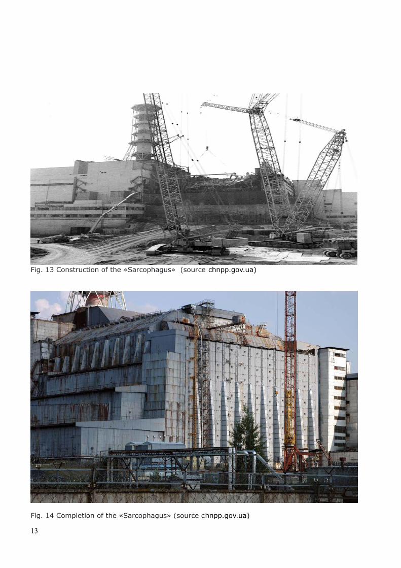
Fig. 13 Construction of the «Sarcophagus» (source chnpp.gov.ua)
Fig. 14 Completion of the «Sarcophagus» (source chnpp.gov.ua)
13

Fig.15 Cross section of the “Sarcophagus” (source chnpp.gov.ua)
Fig. 16 View of Chernobyl plant following the completion of “sarcophagus” (source: chnpp.gov.ua )
14
3. EBRD Nuclear Safety Fund
Following the Chernobyl accident, the G7 launched an initiative in 1993 aimed at the prevention of nuclear accidents within Russian built Nuclear Power Plants. The EBRD-European Bank for Reconstruction and Development was appointed to manage a Fund created by more than 40 donor countries. The RBMK and VVER-230 reactor types targeted by the Fund were:- Ignalina Units 1,2 Lithuania - Kozloduy Units 1,2,3,4 Bulgaria - Saint Petersburg Units 1,2,3,4 Russian Federation - Chernobyl 1,2,3,4 Ukraine added in 1996A budget of € 285 million was initially established. Today the Fund includes more than 40 countries.
The purpose of the Fund was to decommission the selected soviet built nuclear power plants by initially providing a strategy for the site remediation and building several safety facilities. Among them, interim spent fuel storages, radioactive liquid and solid waste treatment and storage plants as well as several protection structures on the plants. In charge of the operation, EBRD established a team called the Nuclear Safety Account including engineers and nuclear specialists. The author of this paper has been a member of the team and has been responsible for the entire decommissioning programme of the Chernobyl anIgnalina power plants. The co-author has been in charge for the Chernobyl Nuclear Power Plant of various tasks including the site remediation, the design of the “object” shelter and the construction supervision of the facilities.
A general procedure to execute all activities and to structure the projects was established as follows: assessment of the safety status of the plant, identification of the safety measures and systems to be built as priority, engagement of consulting firms with the assistance of the European Commission, drafting of detailed specifications, issue tenders and select and engage contractors. The above, under the supervision and approval by the State Nuclear Regulatory Inspectorate of Ukraine (SNRIU) (Nuclear Safety Authority).Following the establishment of a Grant Agreement between EBRD and the Chernobyl Nuclear Power Plant (ChNPP), contracts have been established between this latter and the supplier under control of the Nuclear Safety Account team and payments are carried out directly by EBRD that controls the entire Fund. All projects are managed by the Project Management Units based on the site reporting to the Nuclear Safety Account team.The Assembly of Donors monitors periodically each project.
15
The activity on the Chernobyl plant includes the design and construction of:
a. The new Interim Spent Fuel Storage Facility (ISF-2).b. The Liquid Radioactive Wastes Treatment Plant (LRWTP). c. The Industrial Complex of Solid Radioactive Wastes Management (ICSRWM), later transferred for funding to the European Commission and Ukraine.d. The Shelter Implementation Plan (SIP) (established in 1997). This was carried out within a new Chernobyl Shelter Fund (CSF) with the aim of transforming the existing “sarcophagus” into a stable and environmentally safe system andto seal the damaged reactor Unit 4 by means of the New Safe Confinement.In addition, the Chernobyl Shelter Fund (CSF) provides training facilities, radiation monitoring and medical support including medical equipment, as well as a medical screening programme.
As of 2015, the CSF received € 2.1 billion from 41 countries.
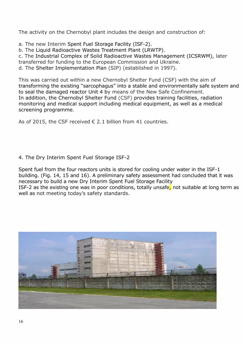
4. The Dry Interim Spent Fuel Storage ISF-2
Spent fuel from the four reactors units is stored for cooling under water in the ISF-1 building. (Fig. 14, 15 and 16). A preliminary safety assessment had concluded that it was necessary to build a new Dry Interim Spent Fuel Storage Facility ISF-2 as the existing one was in poor conditions, totally unsafe, not suitable at long term aswell as not meeting today’s safety standards.
16
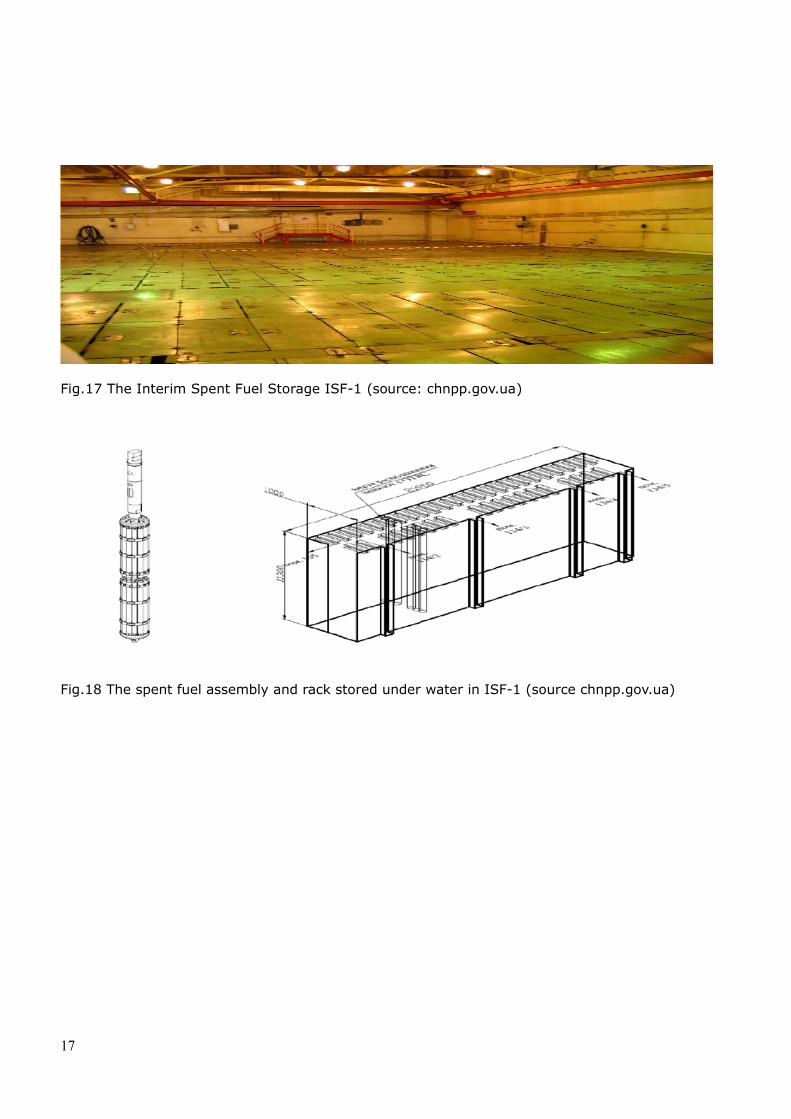
Fig.17 The Interim Spent Fuel Storage ISF-1 (source: chnpp.gov.ua)
Fig.18 The spent fuel assembly and rack stored under water in ISF-1 (source chnpp.gov.ua)
17
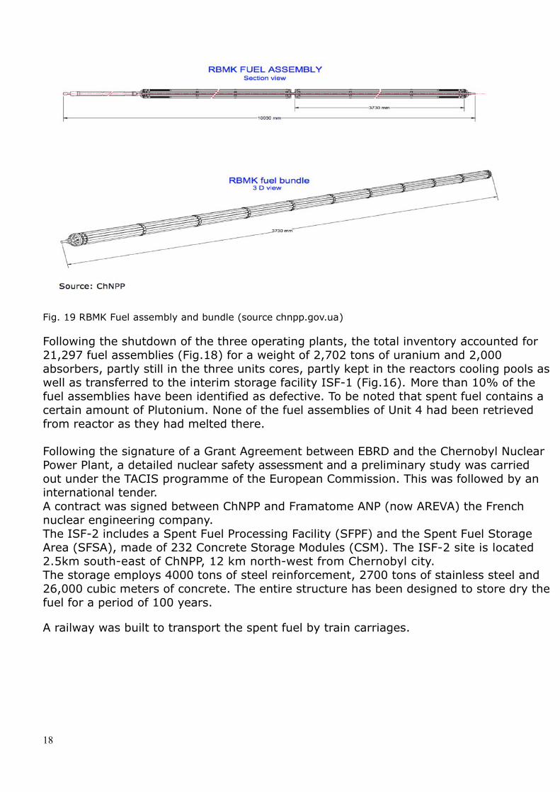
Fig. 19 RBMK Fuel assembly and bundle (source chnpp.gov.ua)
Following the shutdown of the three operating plants, the total inventory accounted for 21,297 fuel assemblies (Fig.18) for a weight of 2,702 tons of uranium and 2,000 absorbers, partly still in the three units cores, partly kept in the reactors cooling pools as well as transferred to the interim storage facility ISF-1 (Fig.16). More than 10% of the fuel assemblies have been identified as defective. To be noted that spent fuel contains a certain amount of Plutonium. None of the fuel assemblies of Unit 4 had been retrieved from reactor as they had melted there.
Following the signature of a Grant Agreement between EBRD and the Chernobyl Nuclear Power Plant, a detailed nuclear safety assessment and a preliminary study was carried out under the TACIS programme of the European Commission. This was followed by an international tender. A contract was signed between ChNPP and Framatome ANP (now AREVA) the French nuclear engineering company. The ISF-2 includes a Spent Fuel Processing Facility (SFPF) and the Spent Fuel Storage Area (SFSA), made of 232 Concrete Storage Modules (CSM). The ISF-2 site is located 2.5km south-east of ChNPP, 12 km north-west from Chernobyl city. The storage employs 4000 tons of steel reinforcement, 2700 tons of stainless steel and 26,000 cubic meters of concrete. The entire structure has been designed to store dry the fuel for a period of 100 years.
A railway was built to transport the spent fuel by train carriages.
18
Framatome ANP had selected the Transnuklear Nuhoms dry casks system in which to store the fuel. (see References). The Nuhoms system consists of an enclosure vessel comprising canisters forming separate confinements to prevent the spread of radioactive materials. Spent fuel is introduced in an internal basket that is then included into a canister. Each canister is placed horizontally in the Nuhoms casks that are then introduced in individual compartments of the heavy concrete storage module built at the ISF-2 site.
A central geological repository for spent fuel and high-level waste is planned to be built beyond 2030. This plan also envisages the decontamination of 1,500 hectares of land containing over 5.55 × 10+15 Becquerel of activity.
During the six years construction, several problems had arisen. Despite the almost completion of the processing building and the concrete housing structures for the Nuhoms casks, the work was interrupted due to design errors and neglecting the fact that water had penetrated through the cladding in some fuel elements assemblies. It was also found that the fuel included some reprocessed uranium and plutonium, for which a different neutron spectrum would require redesign of the storage shielding. Additional problems were caused by considerable costs overruns which raised the cost of the project from the original of € 68 million to € 275 million.
In March 2006, US-based Holtec International submitted to ChNPP a feasibility study for drying the part of the spent fuel that contained water and conducted in November successful testing of the drying facility model. In December, a proposal was submitted to the EBRD donors Assembly for the completion in 52 months of the spent fuel storage project using its technology. EBRD's Safety Review Group recommended that the donors continue funding the project with Holtec as the main contractor.The Framatome ANP contract was terminated in 2007 and following an international audit and arbitration, the company was requested to pay to the utility a compensation of 45 m€.In the same year Holtec signed a contract to complete the ISF-2. The facility final design was approved by the Ukrainian Regulator in October 2010 and the Assembly of Contributors agreed to start its implementation immediately under the total responsibility of Holtec. While still utilising the Nuhoms system, the project utilizes several cutting edge technologies developed by Holtec. Among them an innovative double wall canister, an advanced forced gas dehydration system, and a state-of-the-art hot cell to dismember the RBMK fuel assembly. The first phase of work which lasted 100 weeks, valued at slightly over € 30 million involved the preparation of safety and environmental qualification documents in compliance with Ukrainian norms and standards.The entire work, scheduled to span nearly eight years, involves the supply of 231 double wall canisters manufactured at Holtec's plant in Pittsburgh to be delivered between 2016 and 2019. The contract includes the construction/completion of the processing facility
19

including a hot cell, numerous physical modifications to the site, and issuance of the intermediate and final safety analysis reports. .
20
4.1 Spent fuel transport from the storage, treatment and conditioning process.
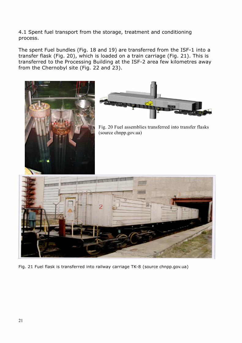
The spent Fuel bundles (Fig. 18 and 19) are transferred from the ISF-1 into a transfer flask (Fig. 20), which is loaded on a train carriage (Fig. 21). This is transferred to the Processing Building at the ISF-2 area few kilometres awayfrom the Chernobyl site (Fig. 22 and 23).
Fig. 20 Fuel assemblies transferred into transfer flasks (source chnpp.gov.ua)
Fig. 21 Fuel flask is transferred into railway carriage TK-8 (source chnpp.gov.ua)
21
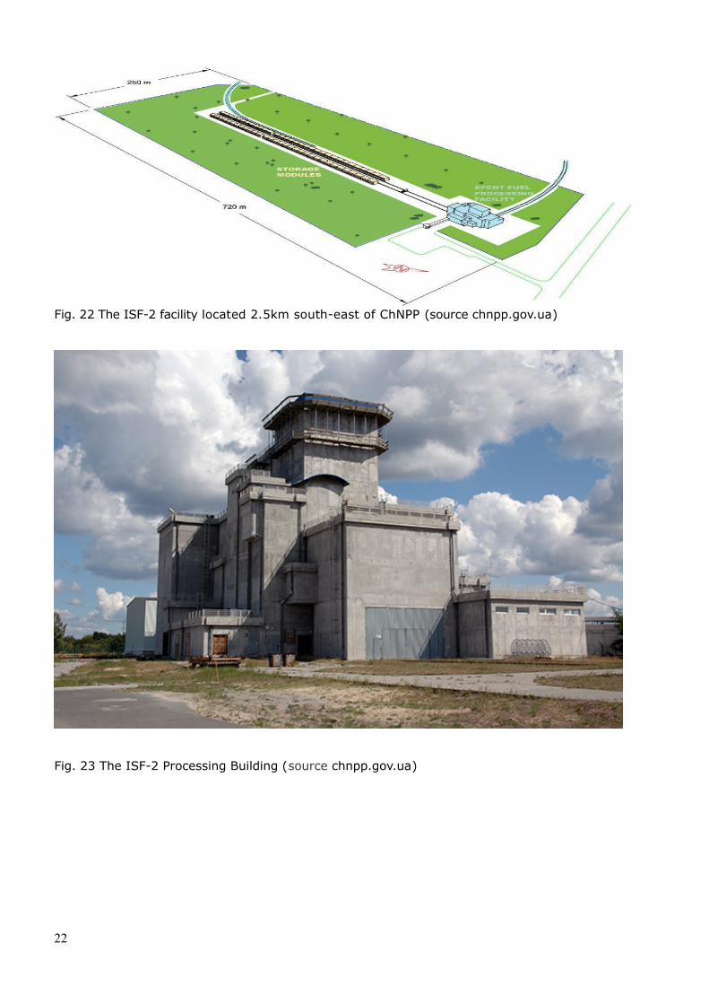
Fig. 22 The ISF-2 facility located 2.5km south-east of ChNPP (source chnpp.gov.ua)
Fig. 23 The ISF-2 Processing Building (source chnpp.gov.ua)
22
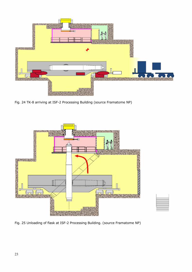
Fig. 24 TK-8 arriving at ISF-2 Processing Building (source Framatome NP)
Fig. 25 Unloading of flask at ISF-2 Processing Building. (source Framatome NP)
23
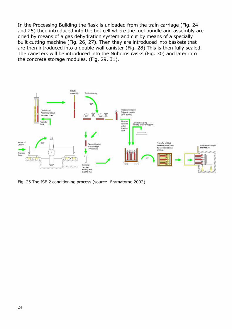
In the Processing Building the flask is unloaded from the train carriage (Fig. 24 and 25) then introduced into the hot cell where the fuel bundle and assembly aredried by means of a gas dehydration system and cut by means of a specially built cutting machine (Fig. 26, 27). Then they are introduced into baskets that are then introduced into a double wall canister (Fig. 28) This is then fully sealed. The canisters will be introduced into the Nuhoms casks (Fig. 30) and later into the concrete storage modules. (Fig. 29, 31).
Fig. 26 The ISF-2 conditioning process (source: Framatome 2002)
24
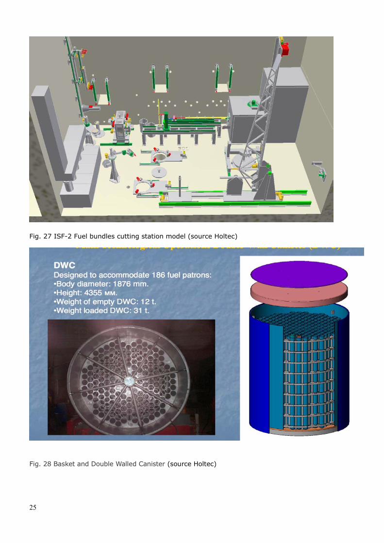
Fig. 27 ISF-2 Fuel bundles cutting station model (source Holtec)
Fig. 28 Basket and Double Walled Canister (source Holtec)
25
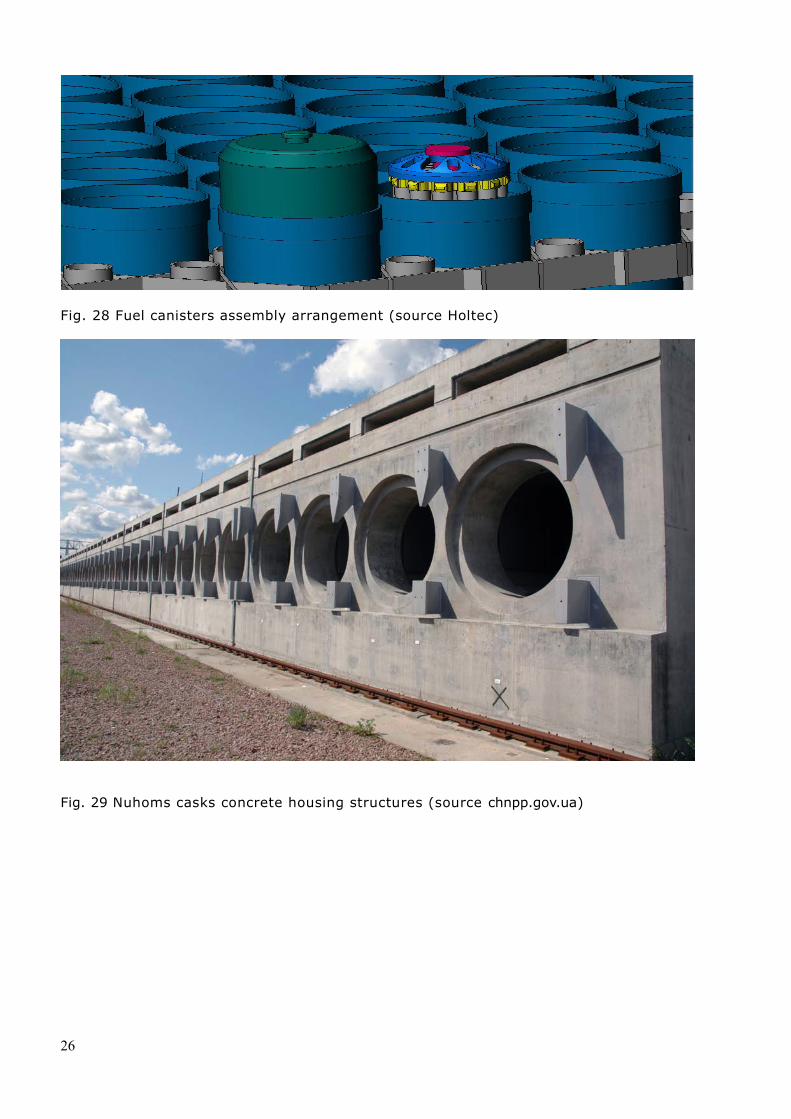
Fig. 28 Fuel canisters assembly arrangement (source Holtec)
Fig. 29 Nuhoms casks concrete housing structures (source chnpp.gov.ua)
26
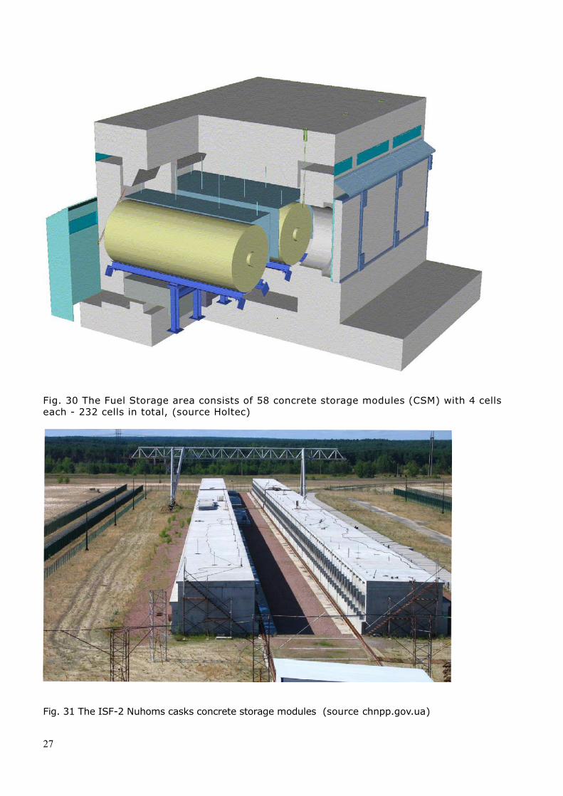
Fig. 30 The Fuel Storage area consists of 58 concrete storage modules (CSM) with 4 cells each - 232 cells in total, (source Holtec)
Fig. 31 The ISF-2 Nuhoms casks concrete storage modules (source chnpp.gov.ua)
27
The Double Walled Canisters are to be stored in CSM for a period of 100 years.
Completion of technical tests and the delivery of operating licence by the Safety Authority will take place in October 2017. A first batch of canister manufactured by Holtec has been delivered in December 2015. Total delivery is expected in 2019. The first loading of spent fuel is planned early 2018.The canisters shall be continuously monitored during the entire storage period.
3. Liquid Radioactive Wastes Treatment Plant (LRWTP)
The LRWTP (Fig. 32) is a processing plant for the liquid radioactive wastes stored during operation in five 5,000 m3 and nine 1,000 m3 tanks, as well as during the ChNPP decommissioning. The liquids include perlites, resins and evaporator concentrates. The LRWTP also processes the liquids produced during ChNPP decommissioning, the construction of the NSC- New Safe Confinement as well as other operations on site. The plant includes:
Liquid Radioactive Waste (LRW) retrieval system from existing storages. Transportation system to the treatment installation. Treatment installations including evaporation, solid state cementation and immobilization in casks. Delivery of casks to the Vektor Complex disposal located in the Exclusion zone.
The plant, designed by Tractebel, was built by the consortium Belgatom (Belgium), Ansaldo (Italy), SGN (France).
28
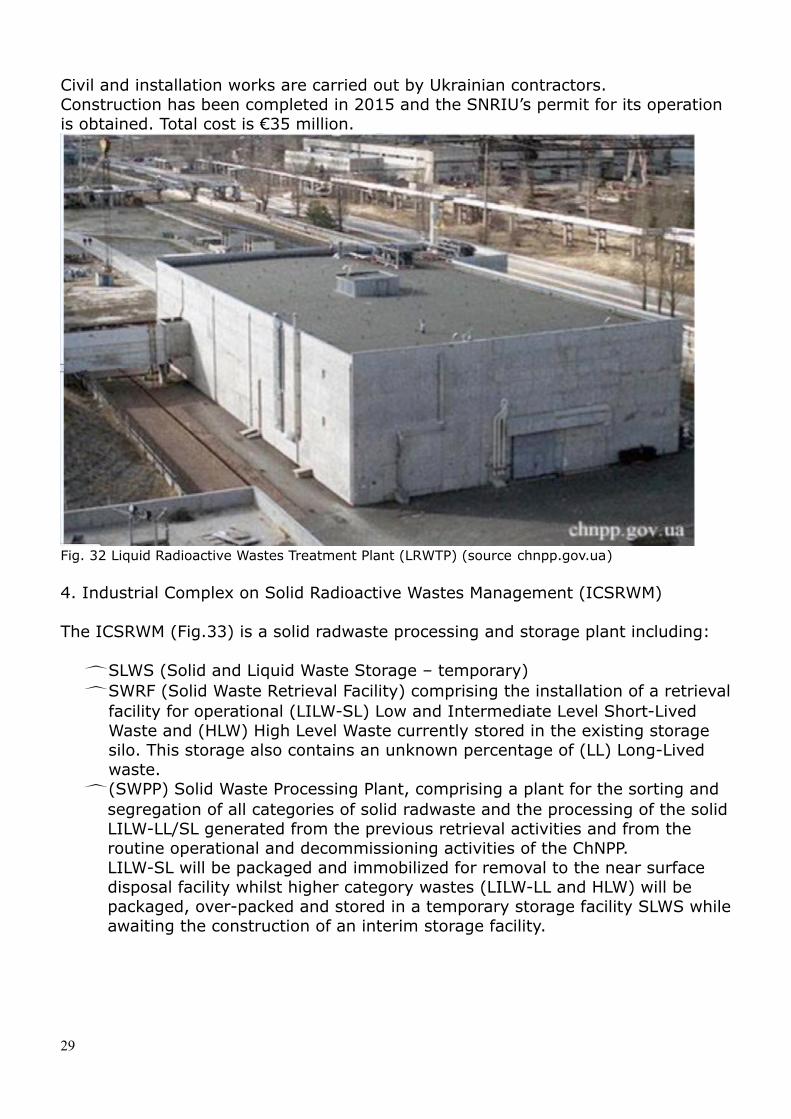
Civil and installation works are carried out by Ukrainian contractors.Construction has been completed in 2015 and the SNRIU’s permit for its operation is obtained. Total cost is €35 million.
Fig. 32 Liquid Radioactive Wastes Treatment Plant (LRWTP) (source chnpp.gov.ua)
4. Industrial Complex on Solid Radioactive Wastes Management (ICSRWM)
The ICSRWM (Fig.33) is a solid radwaste processing and storage plant including:
SLWS (Solid and Liquid Waste Storage – temporary) SWRF (Solid Waste Retrieval Facility) comprising the installation of a retrieval
facility for operational (LILW-SL) Low and Intermediate Level Short-Lived Waste and (HLW) High Level Waste currently stored in the existing storage silo. This storage also contains an unknown percentage of (LL) Long-Lived waste.
(SWPP) Solid Waste Processing Plant, comprising a plant for the sorting and segregation of all categories of solid radwaste and the processing of the solid LILW-LL/SL generated from the previous retrieval activities and from the routine operational and decommissioning activities of the ChNPP. LILW-SL will be packaged and immobilized for removal to the near surface disposal facility whilst higher category wastes (LILW-LL and HLW) will be packaged, over-packed and stored in a temporary storage facility SLWS whileawaiting the construction of an interim storage facility.
29
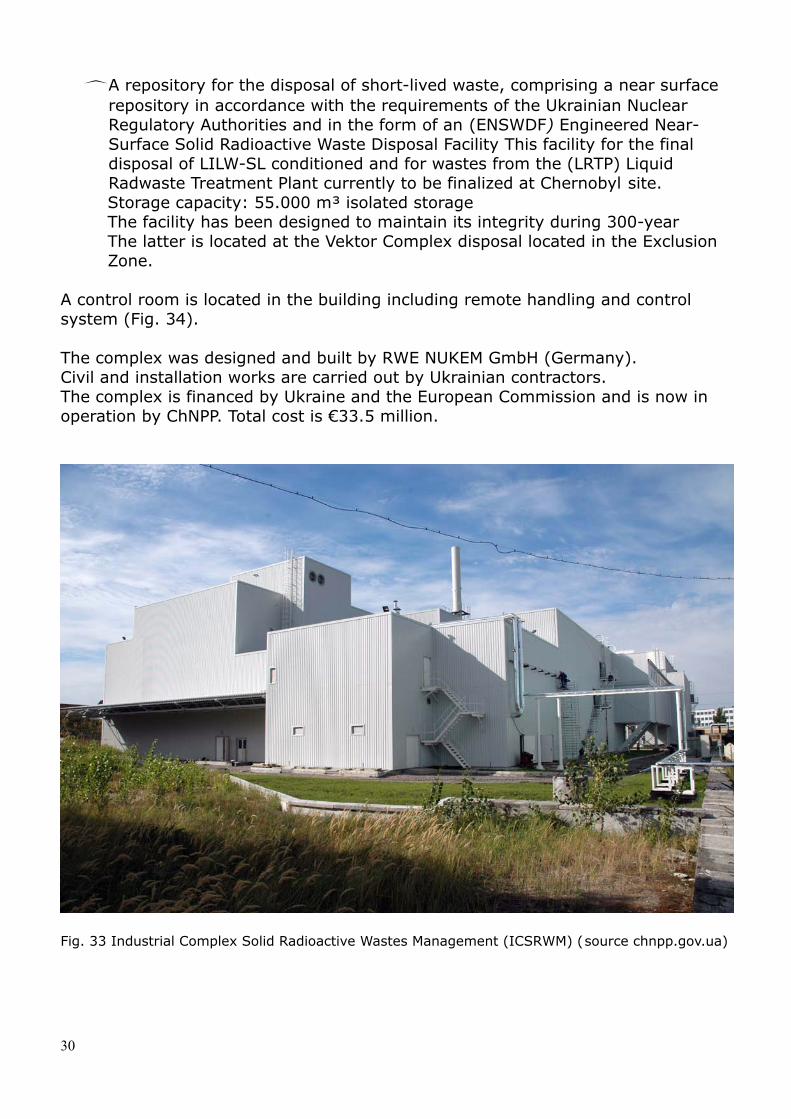
A repository for the disposal of short-lived waste, comprising a near surface repository in accordance with the requirements of the Ukrainian Nuclear Regulatory Authorities and in the form of an (ENSWDF) Engineered Near-Surface Solid Radioactive Waste Disposal Facility This facility for the final disposal of LILW-SL conditioned and for wastes from the (LRTP) Liquid Radwaste Treatment Plant currently to be finalized at Chernobyl site. Storage capacity: 55.000 m³ isolated storageThe facility has been designed to maintain its integrity during 300-yearThe latter is located at the Vektor Complex disposal located in the Exclusion Zone.
A control room is located in the building including remote handling and control system (Fig. 34).
The complex was designed and built by RWE NUKEM GmbH (Germany).Civil and installation works are carried out by Ukrainian contractors.The complex is financed by Ukraine and the European Commission and is now in operation by ChNPP. Total cost is €33.5 million.
Fig. 33 Industrial Complex Solid Radioactive Wastes Management (ICSRWM) (source chnpp.gov.ua)
30
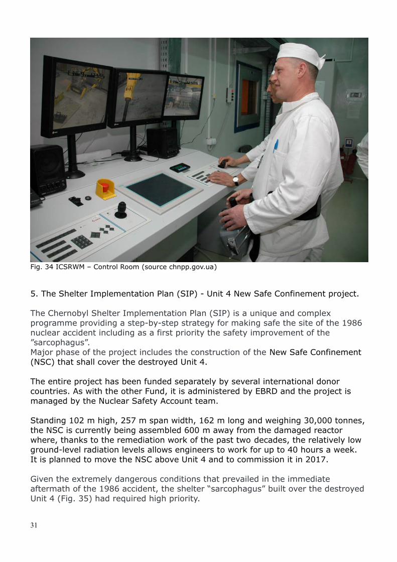
Fig. 34 ICSRWM – Control Room (source chnpp.gov.ua)
5. The Shelter Implementation Plan (SIP) - Unit 4 New Safe Confinement project.
The Chernobyl Shelter Implementation Plan (SIP) is a unique and complex programme providing a step-by-step strategy for making safe the site of the 1986 nuclear accident including as a first priority the safety improvement of the ”sarcophagus”. Major phase of the project includes the construction of the New Safe Confinement (NSC) that shall cover the destroyed Unit 4. The entire project has been funded separately by several international donor countries. As with the other Fund, it is administered by EBRD and the project is managed by the Nuclear Safety Account team.
Standing 102 m high, 257 m span width, 162 m long and weighing 30,000 tonnes, the NSC is currently being assembled 600 m away from the damaged reactor where, thanks to the remediation work of the past two decades, the relatively low ground-level radiation levels allows engineers to work for up to 40 hours a week.It is planned to move the NSC above Unit 4 and to commission it in 2017.
Given the extremely dangerous conditions that prevailed in the immediate aftermath of the 1986 accident, the shelter “sarcophagus” built over the destroyed Unit 4 (Fig. 35) had required high priority.
31
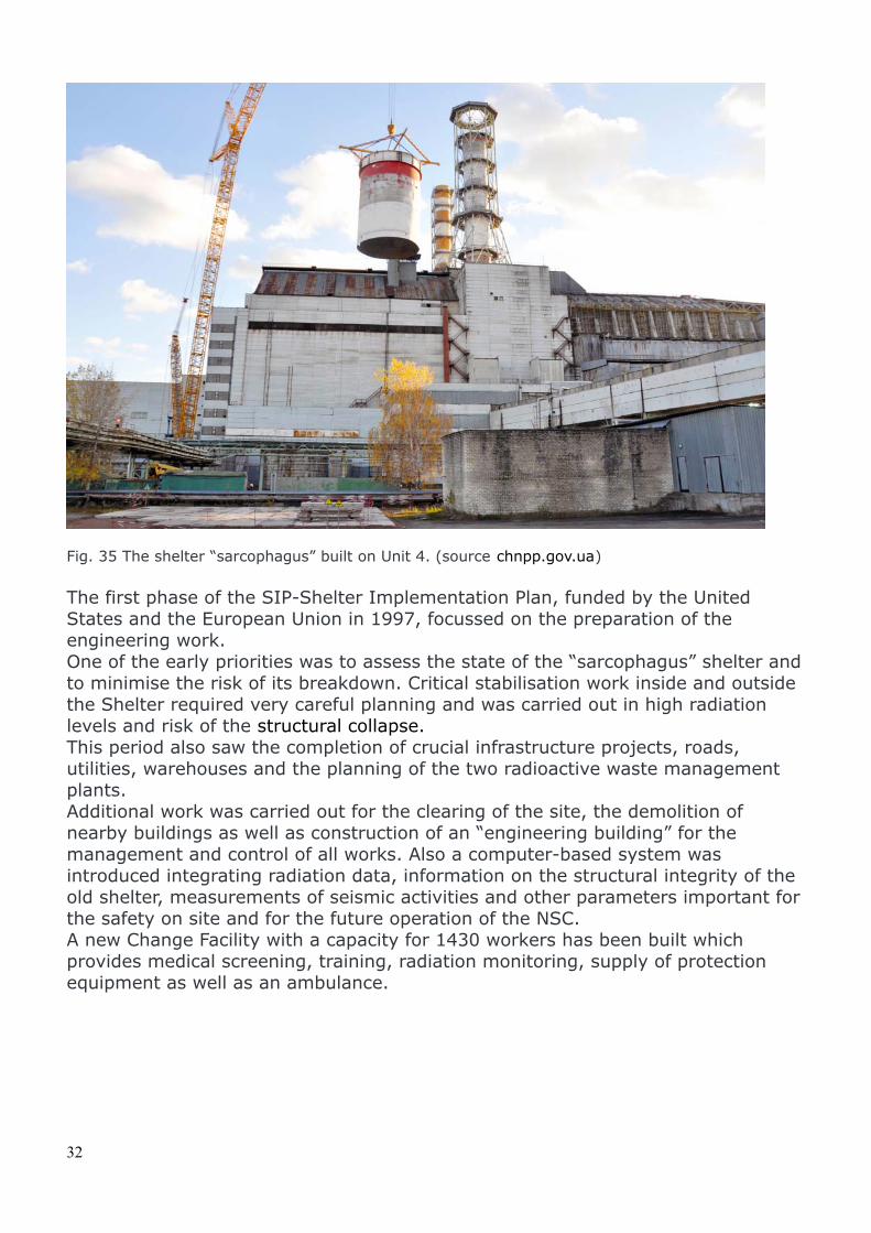
Fig. 35 The shelter “sarcophagus” built on Unit 4. (source chnpp.gov.ua)
The first phase of the SIP-Shelter Implementation Plan, funded by the United States and the European Union in 1997, focussed on the preparation of the engineering work.One of the early priorities was to assess the state of the “sarcophagus” shelter and to minimise the risk of its breakdown. Critical stabilisation work inside and outside the Shelter required very careful planning and was carried out in high radiation levels and risk of the structural collapse.This period also saw the completion of crucial infrastructure projects, roads, utilities, warehouses and the planning of the two radioactive waste management plants.Additional work was carried out for the clearing of the site, the demolition of nearby buildings as well as construction of an “engineering building” for the management and control of all works. Also a computer-based system was introduced integrating radiation data, information on the structural integrity of the old shelter, measurements of seismic activities and other parameters important for the safety on site and for the future operation of the NSC.A new Change Facility with a capacity for 1430 workers has been built which provides medical screening, training, radiation monitoring, supply of protection equipment as well as an ambulance.
32
5.1 Construction of the New Safe Confinement
The NSC is financed by the Chernobyl Shelter Fund, also administered by the EBRD and managed by the Nuclear Safety Account. The Fund was separately established for the construction of a protection structure the existing Shelter facility over the destroyed Unit 4 and bringing it into a stable and environmentally safe condition. To achieve this goal, the CSF-Chernobyl Shelter Fund supports the SIP works, which was launched by international and Ukrainian experts in 1997 in order to initiate a step-by-step safety improvement of the ChNPP site. The development of all related projects financed by the Fund, is carried out by the SIP PMU - Project Management Unit, which is a a department of ChNPP. The EBRD manages the CSF on behalf of the Fund’s Assembly of Contributors.
Some design objectives of SIP had been achieved in 2010 with the purpose of:
- Reducing a potential collapse. Some building structures of the Shelter were reinforced.
- Mitigating the consequences of the Shelter collapse. The dust-suppression system, which provides a protective film on surfaces inside under the Shelter’s roof has been improved. Several measures on emergency planning have been introduced for the entire ChNPP, including the Shelter.
- Improving safety and protection of personnel and the environment. A Fire Protection System and an Integrated Automated Control System have been installed with the purpose of monitoring the status of the Shelter, including the “fuel containing material (FCM)” i.e. the corium, collected in the lower section of the reactor.
The word "confinement" is used instead of the traditional "containment" to emphasize the difference between the "containment" of radioactivity products produced in case of accident that is the major barrier in most reactor buildings, and the "confinement" of radioactive waste that is the primary purpose of the NSC.
The NSC was designed and is being built by the French consortium Novarka with 50/50 partners VINCI Construction Grands Projets and Bouygues Travaux Publics. The contract was signed August 10, 2007 for the estimated amount of $1.4 billion. Due to the complexity of works within a fully radioactive area the budget for completion was increased at €1.54 billion on April 2011.
33
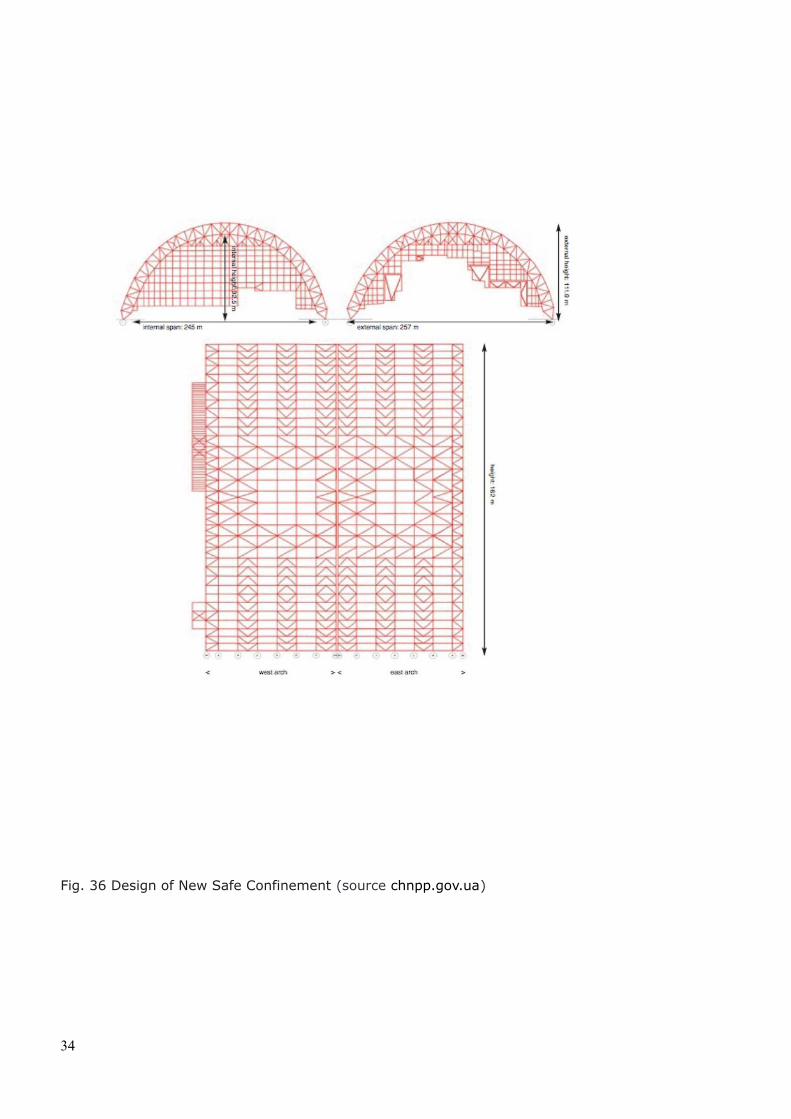
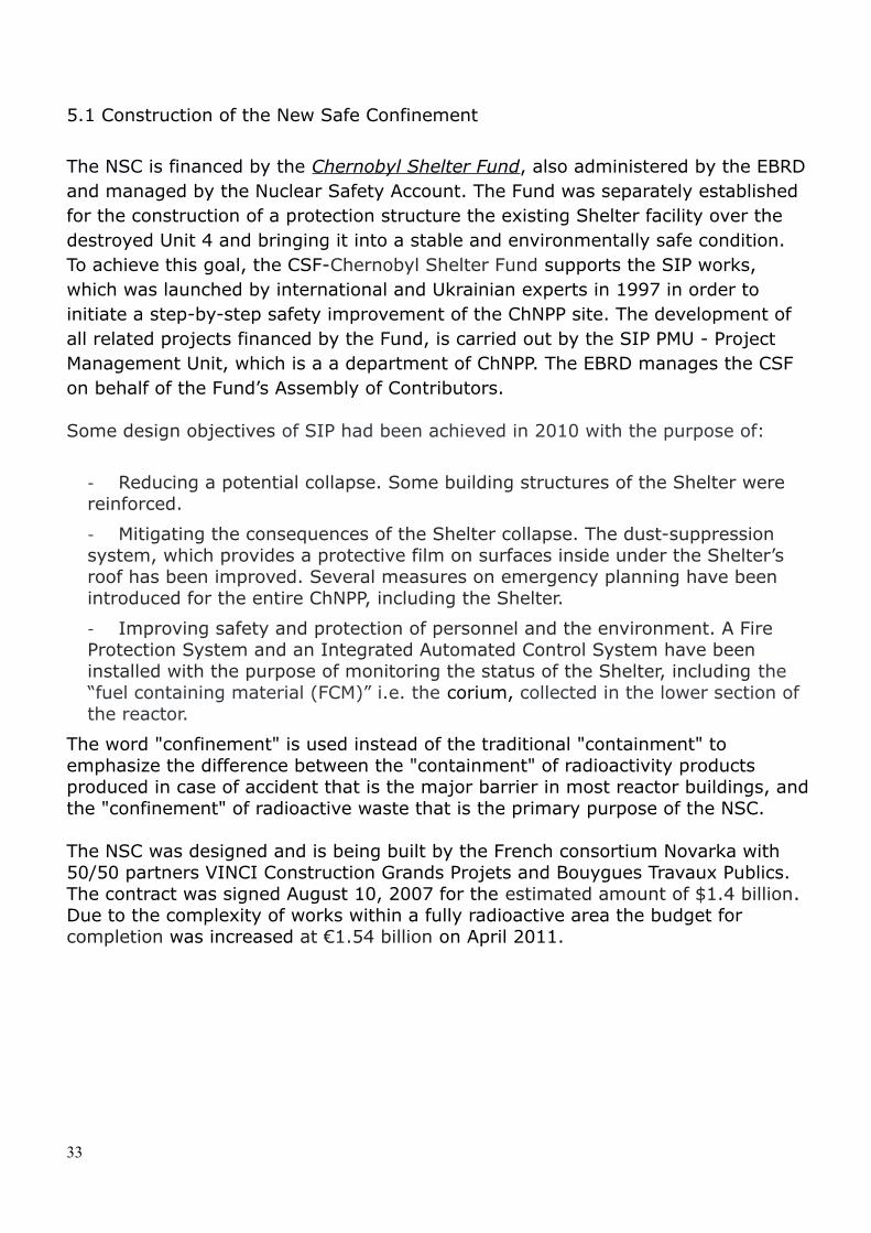
Fig. 36 Design of New Safe Confinement (source chnpp.gov.ua)
34
Fig. 37 Design New Safe Confinement (source chnpp.gov.ua)
The NSC design is an arch-shaped steel structure that has been designed to cover entirely the existing “sarcophagus. Figs. 36 and 37 show a schematic layout of the structure and table shows the dimension of the NSC. The dimensions of the Arch were defined based upon the need to operate equipment inside the NSC and to dismantle the existing “sarcophagus”.
Dimension of New Confinement Structure
Internal height: 92.5 m. (303.5 ft), Distance between the centres of the upper and lower chords of the
Arch: 12 m. (39.4 ft). Internal span of the Arch: 245 m. (803.8 ft), External span: 257 m. (842 ft).Overall length of the structure: 162 m. (531 ft),
consisting of 13 arches 12.5 m.(41 ft) assembled apart to form 12 bays.
35
Weight : 36.479 t
The ends of the structure will be sealed by vertical walls assembled around, but not supported by, the existing structures of the reactor building. The arches are constructed of tubular steel components. Externally, the Arch and end walls are encased with three layer panels with cladding of corrosion-resistant steel, and internally – clad with corrosion-resistant steel.
Major parts of the Arch will be factory-manufactured and delivered to an assembling site located 180 m. (590 ft) westwards from Unit 4 reactor.
Each steel tube will be made of high-strength steel in order to reduce cost and assembly weight. The steel used in construction of the tubular components will have yield strength of no less than 2,500 kg/cm2 (250 MPa, 36,000 psi).
A gap between the internal and the external Arch cladding (inter-arch space) will be created to keep air warmer than outside in order to prevent corrosion. Formation of condensate on the Arch’s structures will be avoided by ventilation, dehumidification of air and maintaining relative humidity not exceeding 40% within inter-arch space.
The foundations of the NSC must meet the primary design requirements: They must support the weight of the NSC Arch. They must support rail tracks across which the NSC can roll 180 m.
(590 ft) from the construction site into a final position above Unit 4. They must minimize the amount of digging and cutting into the upper
layers of the ground, as the upper soil is heavily contaminated with nuclear material scattered during the accident.
The site of the NSC itself is slightly sloped, ranging in elevation from +117.5 m. (385 ft) on the eastern side to +114 m. (374 ft) on the western side. The foundation must account for this difference without extensive site levelling.
The ground upon which the foundation must be built is unique in that it is a “technogenic” (technologically caused layer) one at a depth, approximately, from 2.5 to 3 m. (8 to 10 ft). The “technogenic” layer was created by radioactive contamination from the accident and consists of various materials, including fragments of the reactor core and nuclear fuel, stone, sand, loamy sands, concrete (probably unreinforced) and construction wastes. It was considered unfeasible to determine the geotechnical characteristics of this soil layer. As a result of this, the design of the foundation has taken in consideration the load-bearing properties of the “technogenic” layer.
The ground water level at ChNPP site fluctuates from +109.9 m. (360.6 ft) on average in December and to +110.7 m. (363.2 ft) on average in May.
During the preparation of foundation pits, a bulldozer was employed to lay 100-300 mm layers of non contaminated materials depending on the values of gamma-radiation dose rate on the soil surface. This prevented mixing the grounds having different levels of radioactive contamination as well to reduce radioactive dose to the workers on the most contaminated area of the site.
36
The NSC foundations consist of three sections:- Foundations of assembling area, supporting the structures during Arch construction;- Foundations of transport area, by which the Arch will be moved to a design position over the Shelter;- Foundations of service area, which will support the Arch in a design position over the Shelter during whole period of operation.
Foundations of transport area are subsurface strip foundations of 121.81 m length. The strips of assembling area foundations consist of cast reinforced concrete raft of 209.91 m length and 396 driving metal piles of 1.0 m diameter and 25 m length.
Service area foundation is arranged as two pile-supported rafts of 175.275 m length each. A north raft consists of three blocks of 58.635 m, 65.335 m and 51.305 m length, and south one – of three blocks of 69.335 m, 54.635 m and 51.305 m length.
The rafts are supported by reinforced concrete inclined piles of 1.0 m diameter and 19.0 m length: 184 piles by south raft and 192 piles by north raft. The rafts have the width ranging from 10.0 m to 11.5 m and 2.0 m to 4.0 m of height.
The foundation is designed to withstand horizontal acceleration structural loads of up to 0.08 g, as well as to withstand a tornado of up to Class F-1.5. However,following a beyond-design-basis analysis carried out later, the design requirement for the structure was later raised to withstand Class F-3.0 tornado.
The NSC is assembled following the sequence: Stabilization of the most unstable and unsafe building structures of the
Shelter. Excavation and construction of the foundations for assembling, transport
and service areas. Assembling of east side of the Arch. Moving the east side of the Arch to a provisional position. Assembling of west side of the Arch. Moving the east side of the Arch east-westwards for joining with west side
of the Arch. Joining of west and east sides of the Arch. Installation of the main cranes system. Sliding of the Arch into a final position over the Shelter. Setting the Arch into a stationary position. Completing the installation of west end wall. Installation of covering joints of east and west walls of the Arch to the
Shelter’s structures.
Once all sections are completed, the complete set of equipment will be installed, including ventilation, radiation monitoring, water-supply systems, as well as electrical systems.
The NSC is being assembled 180 m. (590 ft) westwards of Unit 4 and, when
37
completed, it will be slid into a design position. The actual sliding of the structure along foundation rails is a complex process. (Fig 44). The technology that will be used is derived from bridge construction and balanced cantilever methods.
The sliding rails are two metal plate strips having a rail. On each side of the rail, special fillers of stainless steel and Teflon are installed on the plates. The Arch will be slid into a final position using the hydraulic jack system. To move the Arch, 116 jacking boxes will be used, each of them includes:
- Vertical hydraulic jack (main jack);- A mechanism for horizontal moving with 2 horizontal hydraulic jacks;- Sideward displacement system.
The average sliding speed of the Arch will be 11.2 m. per hour (about 3 mm/s). Sliding is expected to average about 10 m. per hour. The whole sliding process will take 72 hours.
The New Safe Confinement should ensure the dismantling and the strengthening of unstable structures of the building and the Shelter, the retrieval of debris of fuel-containing materials as well as high-level radioactive waste from the destroyed Unit 4. These tasks have been taken in due consideration for the design and construction of the NSC structures that shall support not only the suspended cranes to be used in the demolition, but also the loads of material to be removed.
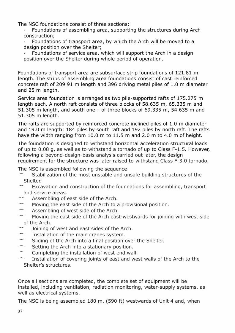
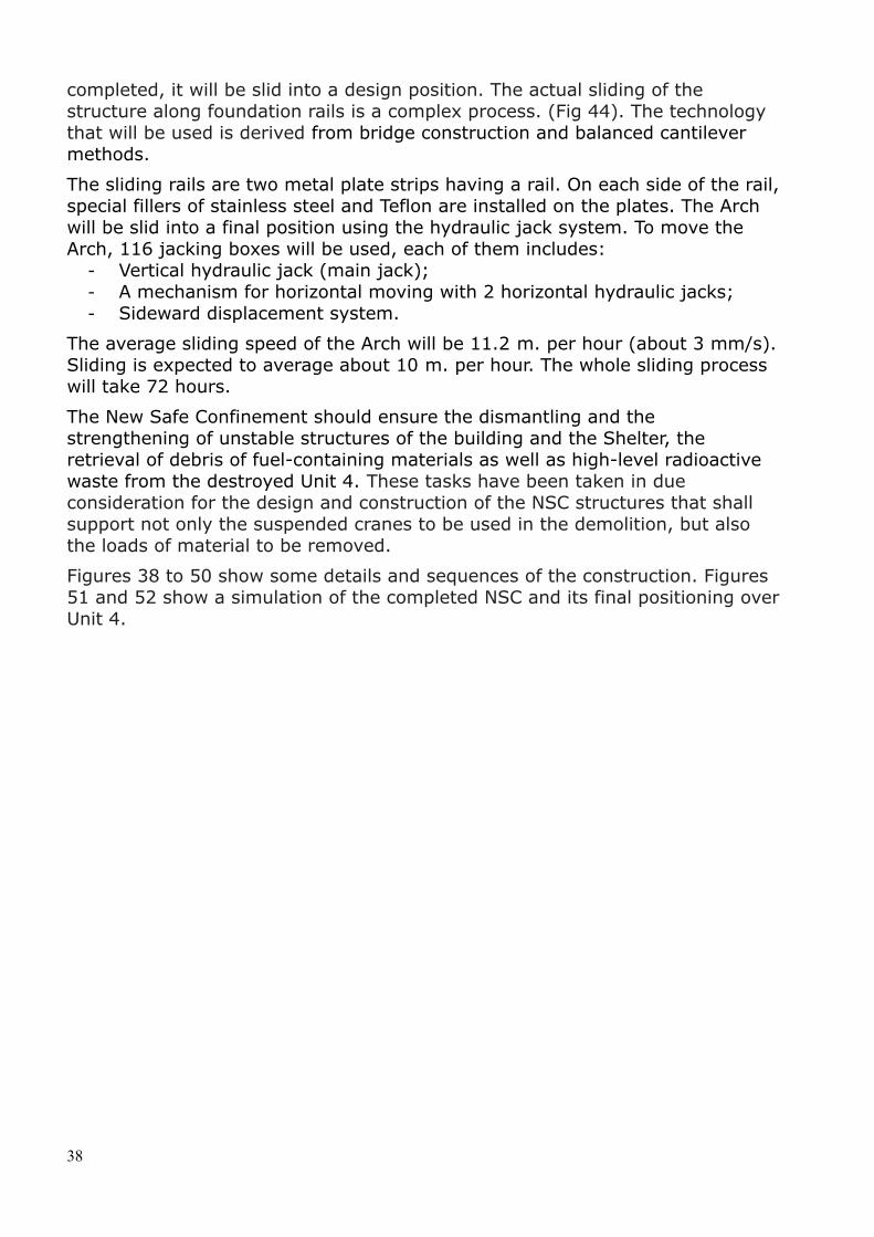
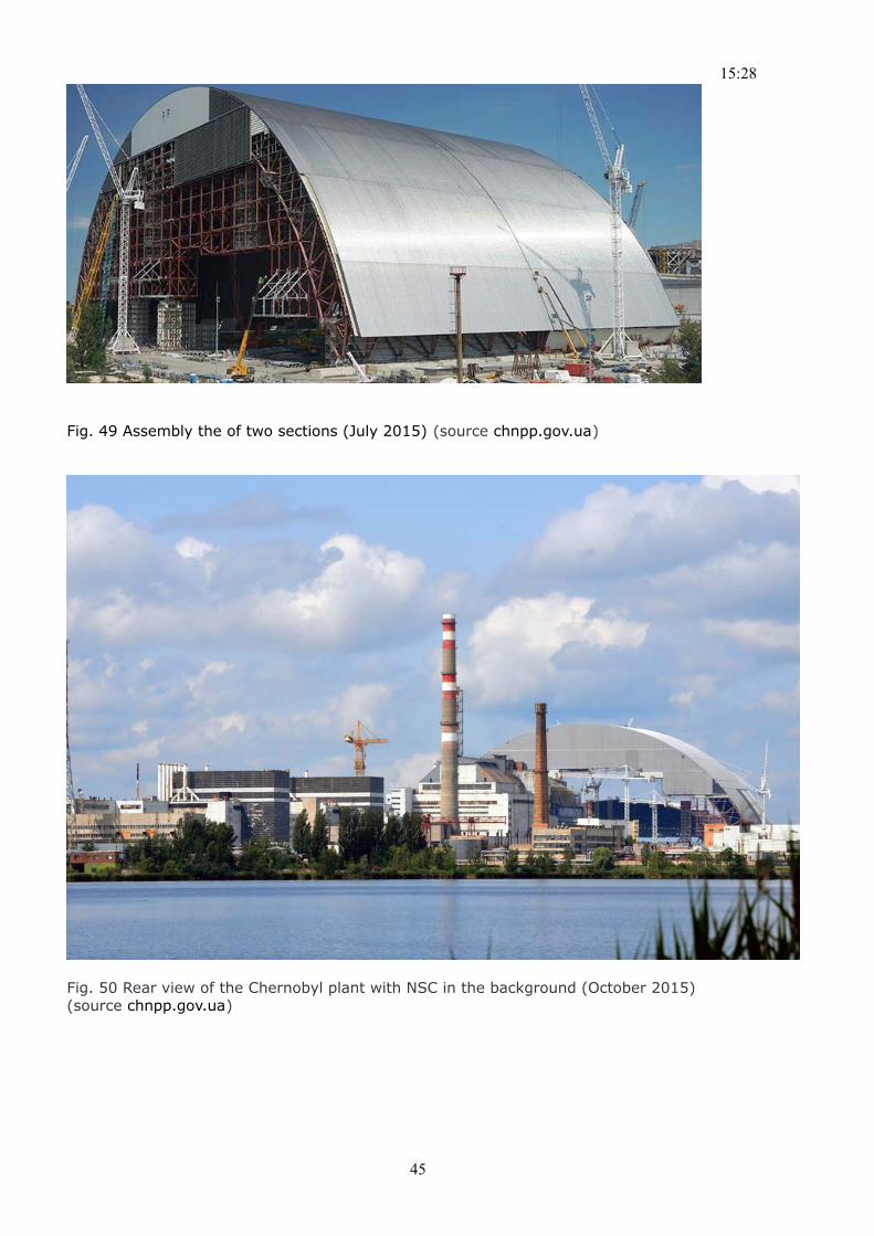
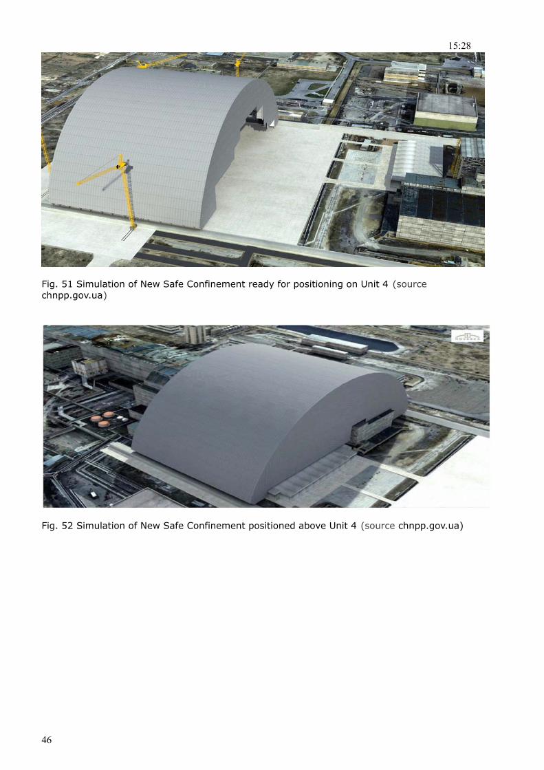
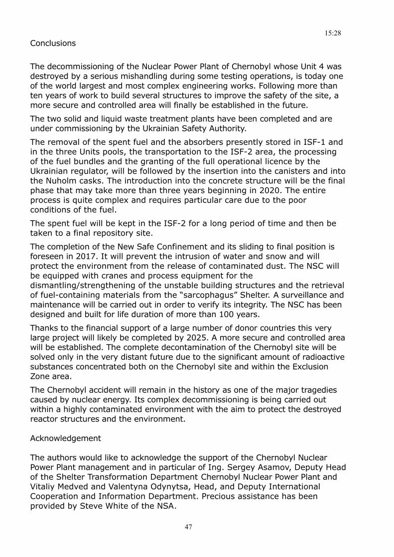
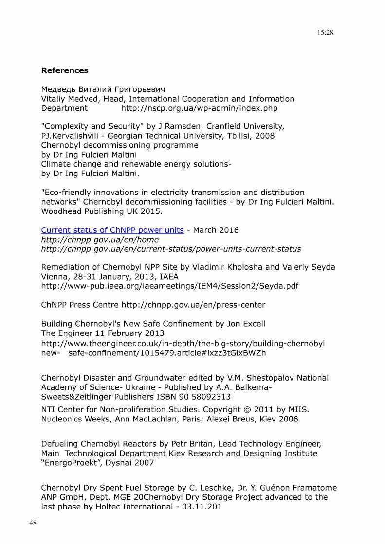
Figures 38 to 50 show some details and sequences of the construction. Figures 51 and 52 show a simulation of the completed NSC and its final positioning over Unit 4.
38
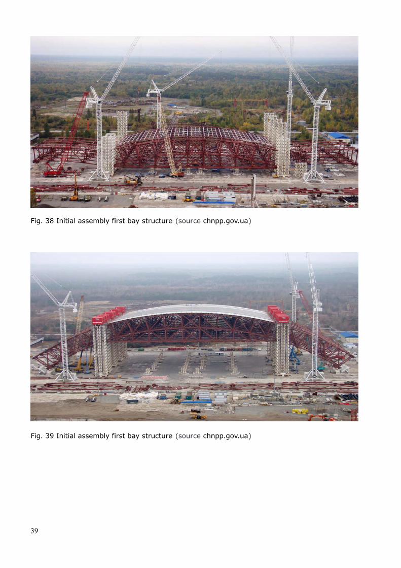
Fig. 38 Initial assembly first bay structure (source chnpp.gov.ua)
Fig. 39 Initial assembly first bay structure (source chnpp.gov.ua)
39
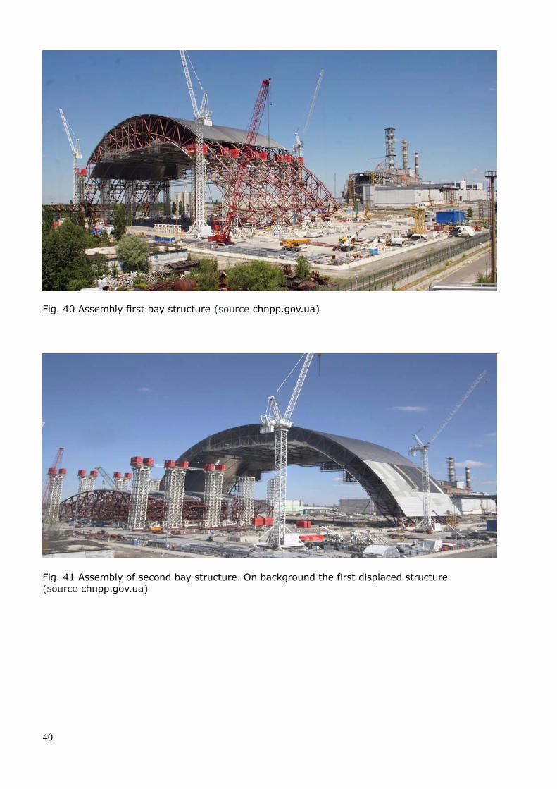
Fig. 40 Assembly first bay structure (source chnpp.gov.ua)
Fig. 41 Assembly of second bay structure. On background the first displaced structure (source chnpp.gov.ua)
40
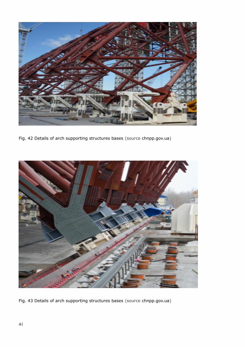
Fig. 42 Details of arch supporting structures bases (source chnpp.gov.ua)
Fig. 43 Details of arch supporting structures bases (source chnpp.gov.ua)
41
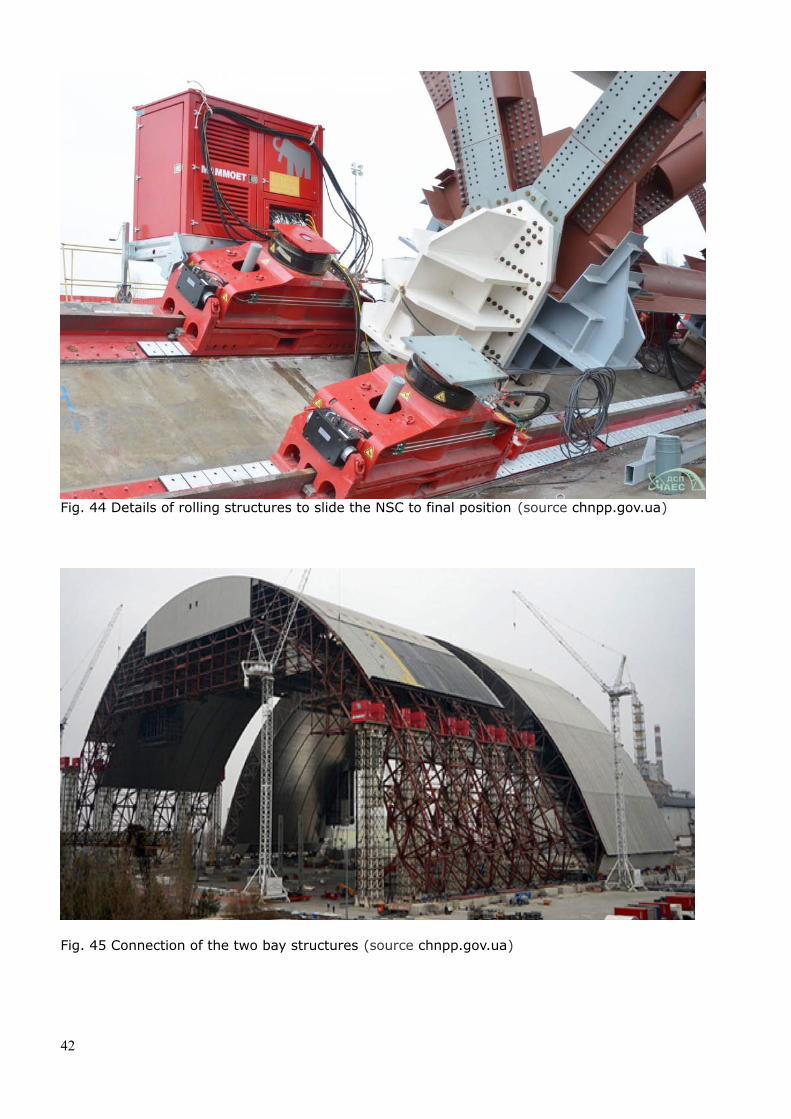
Fig. 44 Details of rolling structures to slide the NSC to final position (source chnpp.gov.ua)
Fig. 45 Connection of the two bay structures (source chnpp.gov.ua)
42
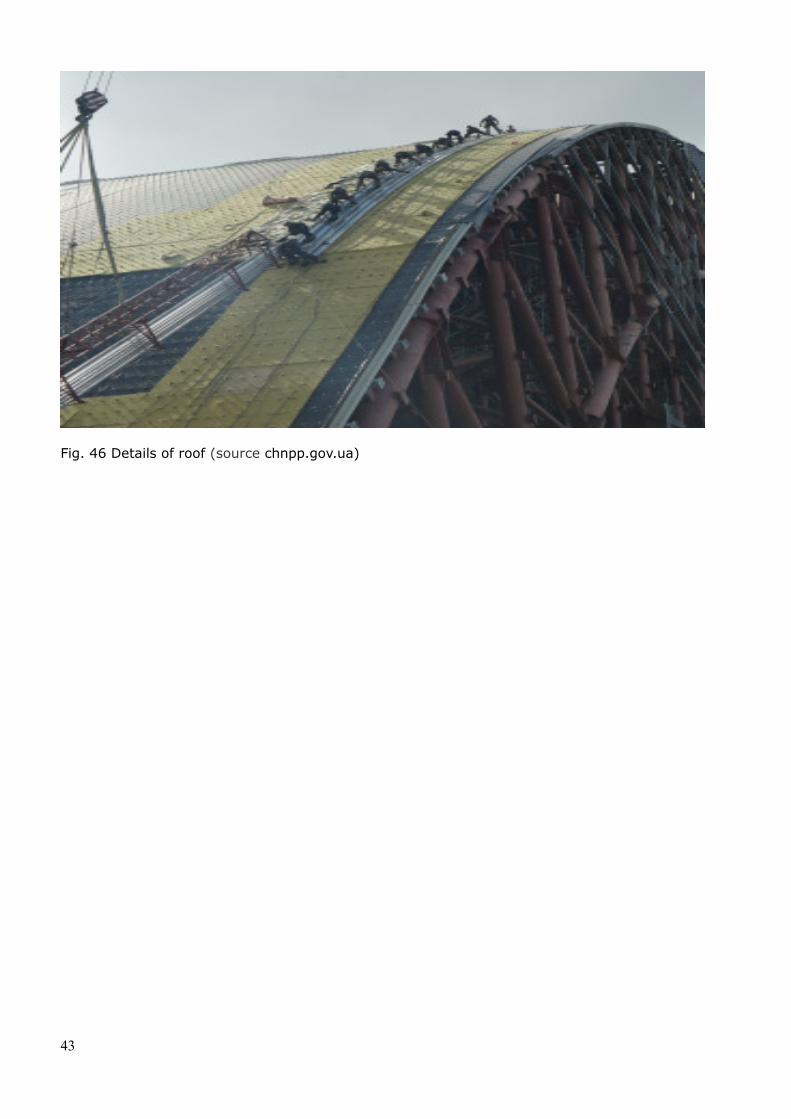
Fig. 46 Details of roof (source chnpp.gov.ua)
43
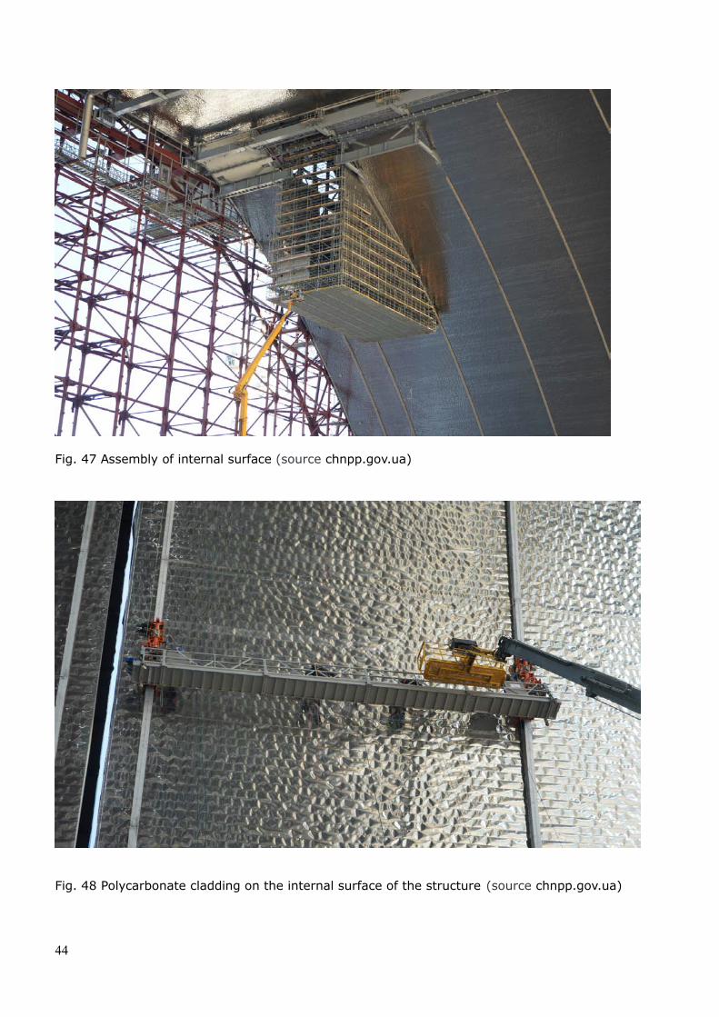
Fig. 47 Assembly of internal surface (source chnpp.gov.ua)
Fig. 48 Polycarbonate cladding on the internal surface of the structure (source chnpp.gov.ua)
44
15:28
Fig. 49 Assembly the of two sections (July 2015) (source chnpp.gov.ua)
Fig. 50 Rear view of the Chernobyl plant with NSC in the background (October 2015) (source chnpp.gov.ua)
45
15:28
Fig. 51 Simulation of New Safe Confinement ready for positioning on Unit 4 (source chnpp.gov.ua)
Fig. 52 Simulation of New Safe Confinement positioned above Unit 4 (source chnpp.gov.ua)
46
15:28
Conclusions
The decommissioning of the Nuclear Power Plant of Chernobyl whose Unit 4 was destroyed by a serious mishandling during some testing operations, is today one of the world largest and most complex engineering works. Following more than ten years of work to build several structures to improve the safety of the site, a more secure and controlled area will finally be established in the future.
The two solid and liquid waste treatment plants have been completed and are under commissioning by the Ukrainian Safety Authority.
The removal of the spent fuel and the absorbers presently stored in ISF-1 and in the three Units pools, the transportation to the ISF-2 area, the processing of the fuel bundles and the granting of the full operational licence by the Ukrainian regulator, will be followed by the insertion into the canisters and into the Nuholm casks. The introduction into the concrete structure will be the final phase that may take more than three years beginning in 2020. The entire process is quite complex and requires particular care due to the poor conditions of the fuel.
The spent fuel will be kept in the ISF-2 for a long period of time and then be taken to a final repository site.
The completion of the New Safe Confinement and its sliding to final position is foreseen in 2017. It will prevent the intrusion of water and snow and will protect the environment from the release of contaminated dust. The NSC will be equipped with cranes and process equipment for the dismantling/strengthening of the unstable building structures and the retrieval of fuel-containing materials from the “sarcophagus” Shelter. A surveillance and maintenance will be carried out in order to verify its integrity. The NSC has been designed and built for life duration of more than 100 years.
Thanks to the financial support of a large number of donor countries this very large project will likely be completed by 2025. A more secure and controlled areawill be established. The complete decontamination of the Chernobyl site will be solved only in the very distant future due to the significant amount of radioactivesubstances concentrated both on the Chernobyl site and within the Exclusion Zone area.
The Chernobyl accident will remain in the history as one of the major tragedies caused by nuclear energy. Its complex decommissioning is being carried out within a highly contaminated environment with the aim to protect the destroyed reactor structures and the environment.
Acknowledgement
The authors would like to acknowledge the support of the Chernobyl Nuclear Power Plant management and in particular of Ing. Sergey Asamov, Deputy Head of the Shelter Transformation Department Chernobyl Nuclear Power Plant and Vitaliy Medved and Valentyna Odynytsa, Head, and Deputy International Cooperation and Information Department. Precious assistance has been provided by Steve White of the NSA.
47
15:28
References
Медведь Виталий ГригорьевичVitaliy Medved, Head, International Cooperation and Information Department http://nscp.org.ua/wp-admin/index.php
"Complexity and Security" by J Ramsden, Cranfield University, PJ.Kervalishvili - Georgian Technical University, Tbilisi, 2008Chernobyl decommissioning programme by Dr Ing Fulcieri MaltiniClimate change and renewable energy solutions-by Dr Ing Fulcieri Maltini.
"Eco-friendly innovations in electricity transmission and distribution networks" Chernobyl decommissioning facilities - by Dr Ing Fulcieri Maltini. Woodhead Publishing UK 2015.
Current status of ChNPP power units - March 2016http://chnpp.gov.ua/en/homehttp://chnpp.gov.ua/en/current-status/power-units-current-status
Remediation of Chernobyl NPP Site by Vladimir Kholosha and Valeriy SeydaVienna, 28-31 January, 2013, IAEA http://www-pub.iaea.org/iaeameetings/IEM4/Session2/Seyda.pdf
ChNPP Press Centre http://chnpp.gov.ua/en/press-center
Building Chernobyl's New Safe Confinement by Jon Excell The Engineer 11 February 2013http://www.theengineer.co.uk/in-depth/the-big-story/building-chernobyl new- safe-confinement/1015479.article#ixzz3tGixBWZh
Chernobyl Disaster and Groundwater edited by V.M. Shestopalov National Academy of Science- Ukraine - Published by A.A. Balkema-Sweets&Zeitlinger Publishers ISBN 90 58092313
NTI Center for Non-proliferation Studies. Copyright © 2011 by MIIS. Nucleonics Weeks, Ann MacLachlan, Paris; Alexei Breus, Kiev 2006
Defueling Chernobyl Reactors by Petr Britan, Lead Technology Engineer, Main Technological Department Kiev Research and Designing Institute “EnergoProekt”, Dysnai 2007
Chernobyl Dry Spent Fuel Storage by C. Leschke, Dr. Y. Guénon Framatome ANP GmbH, Dept. MGE 20Chernobyl Dry Storage Project advanced to the last phase by Holtec International - 03.11.201
48
15:28
Assessment of Radiological and Health Impact-Update of Chernobyl: Ten Years On. 2002."The Seventh Scientific and Practical Conference of the InternationalChornobyl Center and SSE "Chornobyl NPP", 24-27.09.2005
Chernobyl SSE: Interim Spent Nuclear Fuel Dry Storage Facility ISF-2 http://www.chnpp.gov.ua/index.php?option=com askinfo&view =ask info&Itemid=444&lang=enhttp://pbadupws.nrc.gov/docs/ML0415/ML041540170.pdfhttp://us.areva.com/EN/home-3138/areva-inc-areva-tn-used-fuel-storage-system.htmlhttp://us.areva.com/home/liblocal/docs/Solutions/campaigns/Proven_Solutions/NUHOMS.htmlhttp://www.sseb.org/downloads/Presentations/TRU/Easton.pdf
Eurosafe-Safety Review for the Chernobyl Spent Fuel Storage Facility ISF-12008 http://www.eurosafeforum.org/files/Presentations2008/Seminar%202/Abstracts/2.4%20Eurosafe%202008_ISF_1_Gmal_Pretzsch_Damette.pdf
S. Hanson, P. Chollet, International experience of storing spent fuel in systems, International Conference on Storage of Spent Fuel from Power Reactors, IAEA CN-102, 2 - 6 June 2003, Vienna.
Waste Mangement at the Chernobyl NPP - Skripov (ChNPP), V. Tokarevsky (Technocentre), X. Gorge (SGN), J.J. Doublecourt (SGB), F. Billon (SGN), T.D. Brown (AEATechnology) WM’99 Conference, February 28 - March 4, 1999
Chernobyl NPP: The time for practical results has comeBy Aleksandr Likholetov- Center for Energy and Security Studies www.ceness-russia.org November 28, 2011
EuropAid: Background material on EU assistance programme on Nuclear Safety on Chernobyl zone 22-25.02.2011
Trend on SFM and Storage in Central and Eastern Europe by Ferenc Takáts TS Enercon Kft. Budapest, Hungary 20
49

15:28
The author
Dr Ing Fulcieri Maltini is an electrical engineer with a doctorate in Electronics Engineering and a Master in Nuclear Engineering. His international professional career has spanned worldwide from research, industry, consulting and banking.
He has been responsible for the establishment of the safety upgrades programme and the design of the decommissioning facilities of Chernobyl and Ignalina power plants within the EBRD team in charge to fund the closure of the soviet built nuclear power plants.
Besides his expertise in the nuclear fields, his main activity during the last 35 years has been focused around renewable energy projects, energy efficiency, decommissioning of highly complex plants and the financing of projects. As an international expert in technology innovation and in the development of supply chain resources efficiency and sustainability, he closely assists universities, research and SMEs in the industrialisation of high technologies.
He is an advisor to Governments, the European Commission, European Parliament and major international financial institutions and industries.As an expert in nuclear technologies he is actively involved in campaigns against nuclear energy in France, Switzerland, Belgium as well as in Asia and Americas. He writes articles and gives lectures about nuclear technologies and economics.
Fulcieri Maltini is a Senior Life Member of the IEEE-Institute of Electrical and Electronics Engineers, the IEEE Power Energy Society and the IEEE Communications Society.
50