Embed Size (px)
Citation preview

THE CLUSTER MISSION: ESA’S SPACEFLEET TO THEMAGNETOSPHERE
J. CREDLAND, G. MECKE and J. ELLWOODCluster Project Division, ESA Directorate of the Scientific Programme, ESTEC, Noordwijk, The
Netherlands
Abstract. During the first half of 1996, the European Space Agency (ESA) will launch a uniqueflotilla of spacecraft to study the interaction between the solar wind and the Earth’s magnetospherein unprecedented detail. The Cluster mission was first proposed to the Agency in late 1982 andwas selected, together with SOHO, as the Solar Terrestrial Science Programme (STSP), the firstcornerstone of ESA’s Horizon 2000 Programme. It is a complex four-spacecraft mission designedto carry out three-dimensional measurements of the magnetosphere, covering both large- and small-scale phenomena in the sunward and tail regions. The mission is a ‘first’ for ESA in a number ofways:
– the first time that four identical spacecraft have been launched on a single launch vehicle,– the first time that ESA has built spacecraft in true series production and operated them as a
single group,– the first time that European scientific institutes have produced a series of up to five instruments
with full intercalibration, and– the first launch of the Agency’s new heavy launch vehicle Ariane-5.The article gives an overview of this unique mission and the requirements that governed the
spacecraft design. It then describes in detail the resulting design and how the particular engineeringchallenges posed by the series production of four identical spacecraft and sets of scientific instrumentswere met by the combined efforts of the ESA Project Team, Industry and the experiment teams.
1. Mission and System Design
1.1. MISSION OVERVIEW
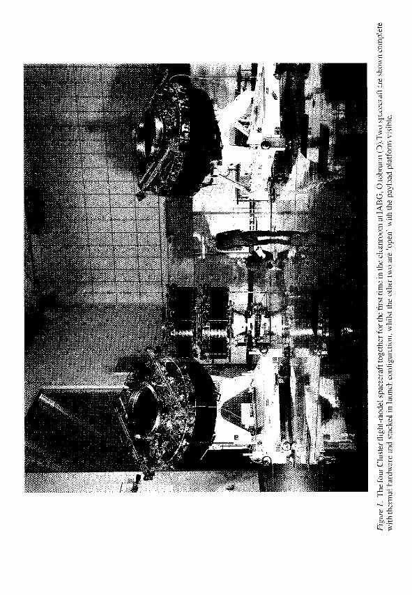
The Cluster mission is an in-situ investigation of plasma processes in the Earth’smagnetosphere using four identical spacecraft simultaneously (Figure 1). It willpermit the accurate determination of three-dimensional and time-varying phenom-ena and will make it possible to distinguish between spatial and temporal variations.
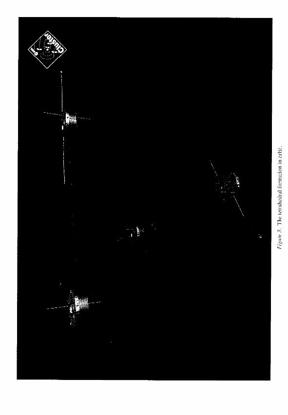
The four Cluster spacecraft will be placed in nearly identical, highly eccentricpolar orbits, with a nominal apogee of 19.6RE and a perigee of 4 RE (Figure 2).This nominal orbit is essentially inertially fixed, so that in the course of the two-yearmission a detailed examination may be made of all significant regions of the mag-netosphere. The plane of this orbit bisects the geomagnetic tail at apogee duringthe northern-hemisphere summer, and passes through the northern cusp region ofthe magnetosphere six months later. The operational orbit finally selected for eachspacecraft will depend upon the actual launch date and orbit-transfer scenario, butwill ensure that each is located at a vertex of a pre-determined tetrahedron (Fig-ure 3) when crossing the regions of interest within the magnetosphere. The relative
Space Science Reviews 79: 33–64, 1997.c 1997 Kluwer Academic Publishers. Printed in Belgium.
36 J. CREDLAND ET AL.
separations will be adjusted during the mission to correspond with the spatial scalesof the structures to be studied, and will vary from a few hundred kilometres to a fewEarth radii. The separation manoeuvres will be performed at intervals of approx-imately six months, synchronised with normal orbit-maintenance manoeuvres.
In the programme baseline, all four spacecraft will be injected into GeostationaryTransfer Orbit (GTO) on a single Ariane-5 launch vehicle. The spacecraft willthen be transferred in pairs to their mission orbits through a series of spacecraftpropulsive manoeuvres.
In orbit, the spacecraft will be spin-stabilised at all times. Their attitudes will beselected to ensure a solar-aspect angle of approximately 90�, which optimises theperformance of the spacecraft’s solar-power generator and thermal-control subsys-tem throughout the mission. This attitude will be maintained during manoeuvresin the operational phase of the mission, but it will be necessary to reorient thespacecraft temporarily during the transfer-orbit phase in order to permit specificmanoeuvres to be carried out, as discussed in Section 1.4.
1.2. THE SCIENTIFIC PAYLOAD
The Cluster payload experiments gave rise to some fundamental spacecraft designrequirements, described in more detail in Section 3. In particular, the missiondemands that the spacecraft have a very high degree of electromagnetic and electro-static cleanliness to avoid disturbing the local plasma field or otherwise interferingwith the sensor measurements. The particle experiments all require unobstructedfields of view and a high level of chemical cleanliness to preserve the sensitivity oftheir detectors.
In order to measure the undisturbed local magnetic field to the required sensit-ivity, the fluxgate magnetometer sensors are mounted on booms as far as possiblefrom the main body of the spacecraft.
Each Cluster scientific payload produces data at different rates, depending onits operating mode. In nominal mode, it will deliver data at a rate of 17 kbit/s,but at certain locations within the orbit it will be operated in a ‘burst mode’ of105 kbit s�1. In addition, the Wide Band Data (WBD) experiment produces data atthe very high rate of some 220 kbit s�1, but this experiment will only be operationalfor approximately 30 min of each orbital revolution.
1.3. THE GROUND SEGMENT
The European Space Operations Centre (ESOC) in Darmstadt, Germany, is respons-ible for the Cluster Operations Control Centre (OCC). It will control the four space-craft in their mission orbits via ESA’s Odenwald and Redu ground stations (Ferriand Warhaut, this issue). Additional ESA ground stations will be used during themission’s Launch and Early Orbit Phase (LEOP).
A ground station belonging to NASA’s Deep-Space Network (DSN) will supportthe mission during certain specific scientific operations, when data from the WBD
38 J. CREDLAND ET AL.
experiment is being transmitted at high bit rate. Further NASA/DSN support willused to back up the ESA network, including ranging, telemetry acquisition andtelecommand back-up functions during the critical transfer-orbit phase.
Orbit determination for all mission phases will also be performed by ESOC.The Cluster mission requires that the relative separations of the four satellites bedetermined to within 1% or 10 km, whichever is the smaller. This will be achievedby determining the orbit of each spacecraft individually from the ground.
Simultaneous acquisition of two or more spacecraft from one ground stationis not planned. The OCC, however, is able to monitor and control two spacecraftsimultaneously by using two ground stations. All communications with the space-craft will be in S-band, and the up- and down-links of each individual satellite areassigned different frequencies.
1.4. MISSION OPERATIONS
The mission is divided into several distinct phases, each with specific operationalobjectives. One special feature of this mission is that the four spacecraft will becontrolled in a time-sharing mode, presenting the OCC with an unusually complextask. This will be particularly true during the early mission phases, when manycritical operations will have to be performed under strict time constraints. Thespacecraft design therefore includes a degree of autonomy and a flexible on-boardsoftware concept to make it easier to meet these operational requirements.
In the Launch and Early Orbit Phase (LEOP), following injection into GTO byAriane, ground contact will be established with all four spacecraft at the earliestpossible opportunity. This will permit a quick-look status verification of essen-tial parameters, which will be followed by less time-critical checkout and orbit-determination activities.
The Transfer-Orbit Phase (TOP) is characterised by a number of large orbit-profile and inclination-change manoeuvres, to target the spacecraft into the desiredmission orbits. The spacecraft attitude will be temporarily adjusted for each ofthese manoeuvres to align the single main engine with the desired thrust direction.Throughout the TOP, the four spacecraft will be treated as two pairs, and injectedwith an interval of approximately 40 hr between spacecraft pairs.
Once in mission orbit, a Commissioning and Verification Phase (CVP) willcommence, which will be devoted mainly to payload operations. These includethe deployment of the two rigid radial booms, followed by the deployment of theflexible wire booms, the experiment check-out, and the calibration activities.
During the main Mission Operations Phase (MOP), the primary objective isto maximise the scientific data return from the payload. The areas of scientificinterest within the orbit will vary seasonally, and do not generally coincide withreal-time ground contacts. To accommodate these, in the nominal operating modethe scientific data will be stored on on-board solid- state memory units, which
THE CLUSTER MISSION: ESA’S SPACEFLEET TO THE MAGNETOSPHERE 39
will then dump the data, together with the real-time telemetry, during subsequentground-contact periods (Sørensen et al. this issue) .
1.5. LAUNCH CAMPAIGN
The Cluster launch campaign started in late August 1995 to meet a by then declared,slightly delayed launch date of 17 January, 1996 for Ariane-5’s first flight (V501).A natural break point occurred in the programme in November 1995 with thecompletion of all electrical checks and prior to spacecraft fuelling. The launchcampaign was suspended at this point and the four spacecraft were sealed in theircontainers for temporary storage. Following declaration of 15 May, 1996 as theearliest expected launch date, the campaign recommenced in early February. Thetransfer of 650 kg of fuel to each spacecraft was completed at the end of March.The launch date has now been confirmed for late May and the batteries have beenintegrated in preparation for the mating of the four spacecraft with the launchvehicle.
1.6. THE INDUSTRIAL TEAM
The Invitation to Tender for the Cluster mission was issued by the Agency in mid-1988. Following a phase of industrial competition, the Prime Contractorship wasawarded to Dornier in Summer 1989.
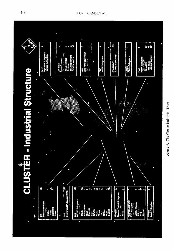
Phase-B, the design phase, commenced in October 1989 with a core team ofcontractors already selected with the Dornier proposal. The full industrial team(Figure 4) was built up during this phase, with lower-tier subcontractors beingselected on a technical-competence and price basis to achieve the requisite geo-graphical distribution targets set for the project.
The achievement of those geographical-return targets was made easier by anagreement with the ESA Industrial Policy Committee (IPC) that the targets couldbe met for the STSP Cornerstone as a whole, rather than at individual project(SOHO and Cluster) level. Several pieces of equipment (power-distribution unitsand transponders) were in fact procured as common items between the two projectsas a pragmatic way of achieving the required targets.
The main Cluster development programme (Phase-C/D) commenced in April1991 with delivery of the four spacecraft to the Agency in April 1995 as a target.In reality, despite a number of critical setbacks during the programme, delivery byDornier was completed in July 1995, still on schedule for the originally foreseen1 December, 1995 launch date.
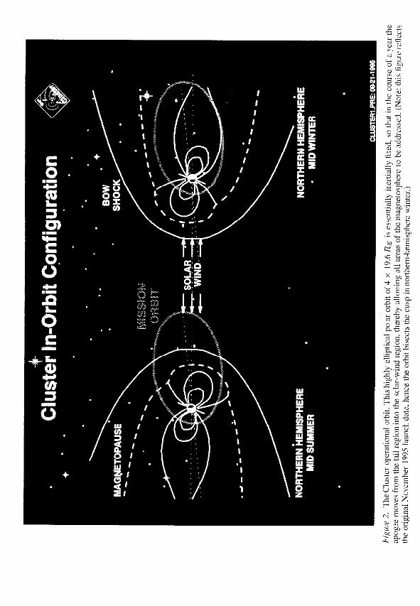
The flight-model system-level environmental test programme was conductedentirely at IABG in Ottobrunn (D) and lasted for two years. During this period,all four Cluster spacecraft successfully underwent sine-vibration, acoustic noise,thermal-balance/vacuum and DC- magnetic testing. The flight model programme,together with the structural-model testing also conducted at IABG in 1992, con-
THE CLUSTER MISSION: ESA’S SPACEFLEET TO THE MAGNETOSPHERE 41
stituted the most extensive test programme of this nature ever undertaken for anyESA project.
2. Spacecraft Design
2.1. MISSION REQUIREMENTS
Long before the start of the Cluster design phase (Phase-B) activities in October1989, a launch date towards the end of 1995 had been fixed. This limited the timeavailable for development, manufacture and testing of the four spacecraft to thatwhich other satellite projects would normally need to deliver only one flight mod-el. Consequently, the logistics for Cluster hardware and software production andverification were crucial, leading to such requirements as modular design at sys-tem level, allowing parallel pre-integration and late exchange of the ProgrammableRead-Only Memory (PROMs) in the Central Data Management Units.
Since the Cluster mission entails scientific measurements on four spacecraftsimultaneously, maximum similarity of the various spacecraft functions on thefour flight models is clearly necessary. Reproducibility of the Cluster hardware atall levels has therefore been of major importance.
The mission orbits selected impose eclipse durations of up to 4 hr and this hasbeen a major design driver for the whole spacecraft system, and for the thermal-control, power and structural subsystems in particular.
Because the development of Cluster and of Ariane-5 have been proceeding inparallel, specific and sometimes severe requirements were imposed on Cluster tocover uncertainties in the launcher development programme. For example, con-servative loads were specified for sine, random and acoustic vibration testing.Nevertheless, very late in the Cluster development programme, in fact after accept-ance of the Cluster hardware, unusually high predicted shock loads originating fromlauncher separations were identified by Ariane, necessitating additional, unforeseenverification activities at unit and system level for Cluster.
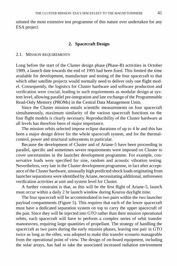
A further constraint is that, as this will be the first flight of Ariane-5, launchmust occur within a daily 2 hr launch window during Kourou daylight time.
The four spacecraft will be accommodated in two pairs within the two launcherpayload compartments (Figure 5). This requires that each of the lower spacecraftmust have a dedicated separation system on top to carry the upper spacecraft ofthe pair. Since they will be injected into GTO rather than their mission operationalorbits, each spacecraft will have to perform a complex series of orbit transfermanoeuvres, requiring large quantities of propellant. The strategy of handling thespacecraft as two pairs during the early mission phases, leaving one pair in GTOtwice as long as the other, was adopted to make this transfer scenario manageablefrom the operational point of view. The design of on-board equipment, includingthe solar arrays, has had to take the associated increased radiation environment
THE CLUSTER MISSION: ESA’S SPACEFLEET TO THE MAGNETOSPHERE 43
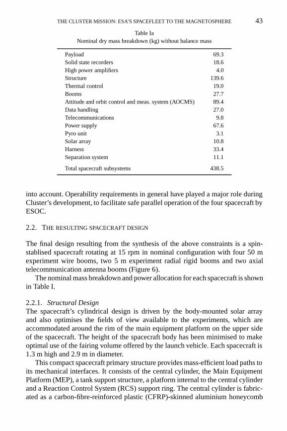
Table IaNominal dry mass breakdown (kg) without balance mass
Payload 69.3Solid state recorders 18.6High power amplifiers 4.0Structure 139.6Thermal control 19.0Booms 27.7Attitude and orbit control and meas. system (AOCMS) 89.4Data handling 27.0Telecommunications 9.8Power supply 67.6Pyro unit 3.1Solar array 10.8Harness 33.4Separation system 11.1
Total spacecraft subsystems 438.5
into account. Operability requirements in general have played a major role duringCluster’s development, to facilitate safe parallel operation of the four spacecraft byESOC.
2.2. THE RESULTING SPACECRAFT DESIGN
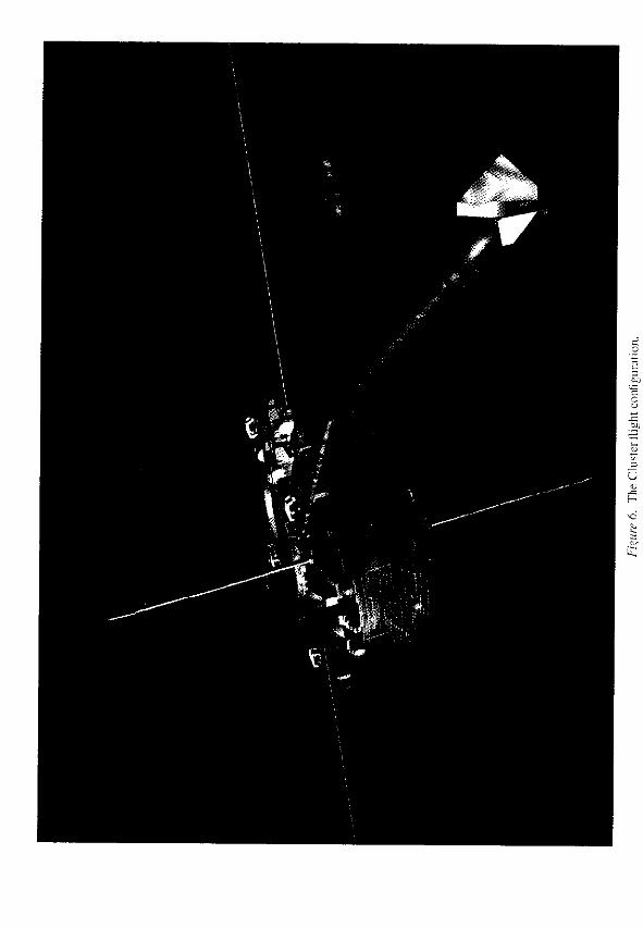
The final design resulting from the synthesis of the above constraints is a spin-stablised spacecraft rotating at 15 rpm in nominal configuration with four 50 mexperiment wire booms, two 5 m experiment radial rigid booms and two axialtelecommunication antenna booms (Figure 6).
The nominal mass breakdown and power allocation for each spacecraft is shownin Table I.
2.2.1. Structural DesignThe spacecraft’s cylindrical design is driven by the body-mounted solar arrayand also optimises the fields of view available to the experiments, which areaccommodated around the rim of the main equipment platform on the upper sideof the spacecraft. The height of the spacecraft body has been minimised to makeoptimal use of the fairing volume offered by the launch vehicle. Each spacecraft is1.3 m high and 2.9 m in diameter.
This compact spacecraft primary structure provides mass-efficient load paths toits mechanical interfaces. It consists of the central cylinder, the Main EquipmentPlatform (MEP), a tank support structure, a platform internal to the central cylinderand a Reaction Control System (RCS) support ring. The central cylinder is fabric-ated as a carbon-fibre-reinforced plastic (CFRP)-skinned aluminium honeycomb
THE CLUSTER MISSION: ESA’S SPACEFLEET TO THE MAGNETOSPHERE 45
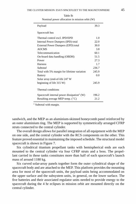
Table IbNominal power allocation in mission orbit (W)
Payload 39.3
Spacecraft bus
Thermal control excl. IPD/EPD 1.0Internal Power Dumpers (IPD) total 22.0External Power Dumpers (EPD) total 30.0AOCMS 3.8Telecommunication 60.1On-board data handling (OBDH) 51.5Power 27.3Harness 1.7Subtotal 236.7Total with 5% margin for lifetime variation 245.9Battery 0.0Solar array (end-of-life 247 Wbeginning of life 315 W) 245.9
Thermal conditions
Spacecraft internal power dissipationa (W) 196.2Resulting average MEP temp. (�C) 21.2
a Subtotal with margin.
sandwich, and the MEP as an aluminium-skinned honeycomb panel reinforced byan outer aluminium ring. The MEP is supported by symmetrically arranged CFRPstruts connected to the central cylinder.
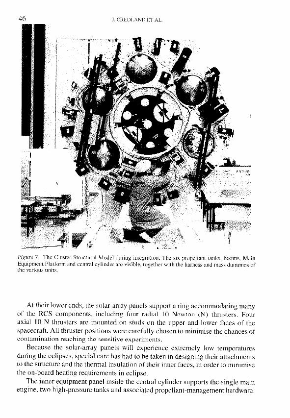
The overall design allows for parallel integration of all equipment with the MEPon one side, and the central cylinder with the RCS components on the other. Thisfeature proved essential in maintaining the imposed schedule. The structural modelspacecraft is shown in Figure 7.
Six cylindrical titanium propellant tanks with hemispherical ends are eachmounted to the central cylinder via four CFRP struts and a boss. The propel-lant carried in these tanks constitutes more than half of each spacecraft’s launchmass of around 1180 kg.
Six curved solar-array panels together form the outer cylindrical shape of thespacecraft body and are attached to the MEP. This platform provides the mountingarea for most of the spacecraft units, the payload units being accommodated onthe upper surface and the subsystem units, in general, on the lower surface. Thefive batteries and their associated regulator units needed to provide energy to thespacecraft during the 4 hr eclipses in mission orbit are mounted directly on thecentral cylinder.
THE CLUSTER MISSION: ESA’S SPACEFLEET TO THE MAGNETOSPHERE 47
The central cylinder carries aluminium interface rings at both its upper andlower ends. The lower ring is compatible with the Ariane 1194 mm diameteradaptor and separation mechanism. The upper ring simulates the interface offeredby the adaptor and is equipped with a separation mechanism. This allows twospacecraft to be stacked on top of one another, whilst themselves still remainingidentical to the maximum extent possible.
Two rigid, double-hinged radial booms on the upper surface of the MEP carrypayload sensors. These booms are stowed for launch, as are the four payloadwire booms and the two rigid, single-hinged antenna booms carrying the S-bandantennas. The rigid booms consist of CFRP tubes with titanium-alloy end fittingsand deployment mechanisms. The radial booms will be deployed mainly by thecentrifugal force developed by the spinning spacecraft, while the antenna boomsare driven by redundant springs.
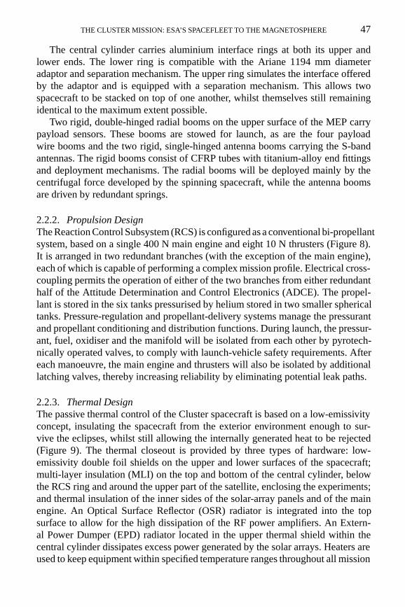
2.2.2. Propulsion DesignThe Reaction Control Subsystem (RCS) is configured as a conventional bi-propellantsystem, based on a single 400 N main engine and eight 10 N thrusters (Figure 8).It is arranged in two redundant branches (with the exception of the main engine),each of which is capable of performing a complex mission profile. Electrical cross-coupling permits the operation of either of the two branches from either redundanthalf of the Attitude Determination and Control Electronics (ADCE). The propel-lant is stored in the six tanks pressurised by helium stored in two smaller sphericaltanks. Pressure-regulation and propellant-delivery systems manage the pressurantand propellant conditioning and distribution functions. During launch, the pressur-ant, fuel, oxidiser and the manifold will be isolated from each other by pyrotech-nically operated valves, to comply with launch-vehicle safety requirements. Aftereach manoeuvre, the main engine and thrusters will also be isolated by additionallatching valves, thereby increasing reliability by eliminating potential leak paths.
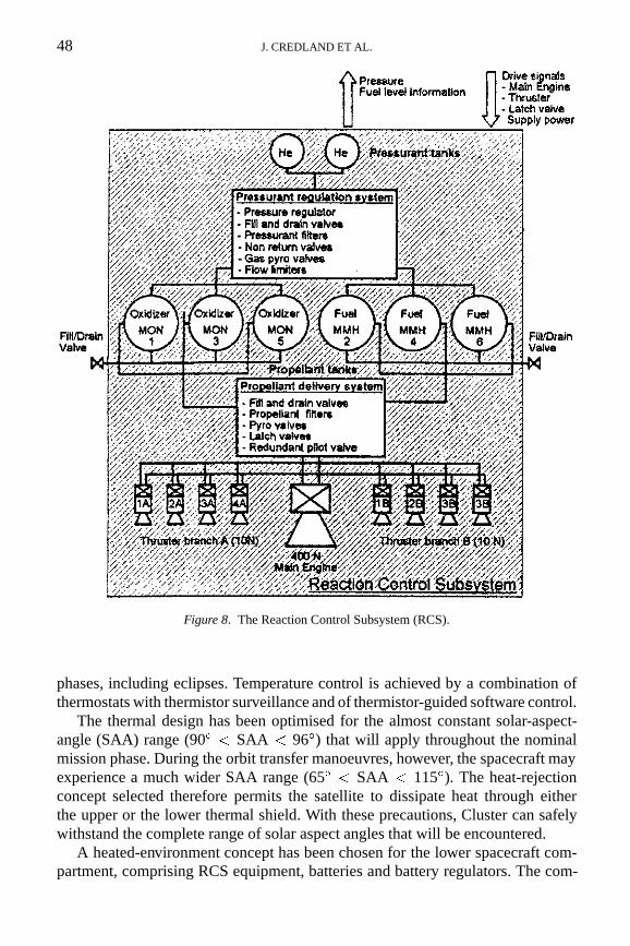
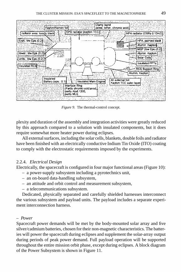
2.2.3. Thermal DesignThe passive thermal control of the Cluster spacecraft is based on a low-emissivityconcept, insulating the spacecraft from the exterior environment enough to sur-vive the eclipses, whilst still allowing the internally generated heat to be rejected(Figure 9). The thermal closeout is provided by three types of hardware: low-emissivity double foil shields on the upper and lower surfaces of the spacecraft;multi-layer insulation (MLI) on the top and bottom of the central cylinder, belowthe RCS ring and around the upper part of the satellite, enclosing the experiments;and thermal insulation of the inner sides of the solar-array panels and of the mainengine. An Optical Surface Reflector (OSR) radiator is integrated into the topsurface to allow for the high dissipation of the RF power amplifiers. An Extern-al Power Dumper (EPD) radiator located in the upper thermal shield within thecentral cylinder dissipates excess power generated by the solar arrays. Heaters areused to keep equipment within specified temperature ranges throughout all mission
48 J. CREDLAND ET AL.
Figure 8. The Reaction Control Subsystem (RCS).
phases, including eclipses. Temperature control is achieved by a combination ofthermostats with thermistor surveillance and of thermistor-guided software control.
The thermal design has been optimised for the almost constant solar-aspect-angle (SAA) range (90� < SAA < 96�) that will apply throughout the nominalmission phase. During the orbit transfer manoeuvres, however, the spacecraft mayexperience a much wider SAA range (65� < SAA < 115�). The heat-rejectionconcept selected therefore permits the satellite to dissipate heat through eitherthe upper or the lower thermal shield. With these precautions, Cluster can safelywithstand the complete range of solar aspect angles that will be encountered.
A heated-environment concept has been chosen for the lower spacecraft com-partment, comprising RCS equipment, batteries and battery regulators. The com-
THE CLUSTER MISSION: ESA’S SPACEFLEET TO THE MAGNETOSPHERE 49
Figure 9. The thermal-control concept.
plexity and duration of the assembly and integration activities were greatly reducedby this approach compared to a solution with insulated components, but it doesrequire somewhat more heater power during eclipses.
All external surfaces, including the solar cells, blankets, double foils and radiatorhave been finished with an electrically conductive Indium Tin Oxide (ITO) coatingto comply with the electrostatic requirements imposed by the experiments.
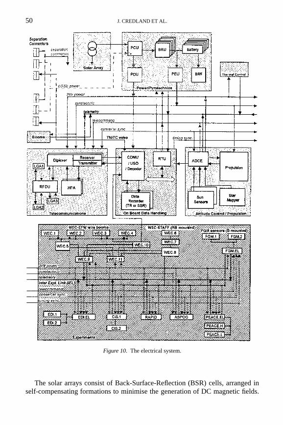
2.2.4. Electrical DesignElectrically, the spacecraft is configured in four major functional areas (Figure 10):
– a power-supply subsystem including a pyrotechnics unit,– an on-board data-handling subsystem,– an attitude and orbit control and measurement subsystem,– a telecommunications subsystem.Dedicated, physically separated and carefully shielded harnesses interconnect
the various subsystem and payload units. The payload includes a separate experi-ment interconnection harness.
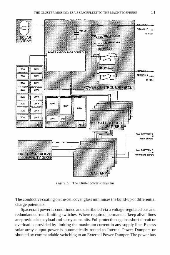
– PowerSpacecraft power demands will be met by the body-mounted solar array and fivesilver/cadmium batteries, chosen for their non-magnetic characteristics. The batter-ies will power the spacecraft during eclipses and supplement the solar-array outputduring periods of peak power demand. Full payload operation will be supportedthroughout the entire mission orbit phase, except during eclipses. A block diagramof the Power Subsystem is shown in Figure 11.
50 J. CREDLAND ET AL.
Figure 10. The electrical system.
The solar arrays consist of Back-Surface-Reflection (BSR) cells, arranged inself-compensating formations to minimise the generation of DC magnetic fields.
THE CLUSTER MISSION: ESA’S SPACEFLEET TO THE MAGNETOSPHERE 51
Figure 11. The Cluster power subsystem.
The conductive coating on the cell cover glass minimises the build-up of differentialcharge potentials.
Spacecraft power is conditioned and distributed via a voltage-regulated bus andredundant current-limiting switches. Where required, permanent ‘keep alive’ linesare provided to payload and subsystem units. Full protection against short-circuit oroverload is provided by limiting the maximum current in any supply line. Excesssolar-array output power is automatically routed to Internal Power Dumpers orshunted by commandable switching to an External Power Dumper. The power bus
52 J. CREDLAND ET AL.
Figure 12. The Cluster On-Board Data-Handling (OBDH) subsystem.
operates on a linear shunt regulation approach, rendering the main bus voltageextremely ‘clean’ during payload measurement periods. This significantly reducesany potential electromagnetic disturbances due to the power subsystem.
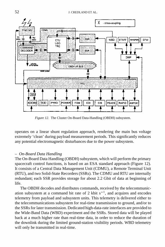
– On-Board Data HandlingThe On-Board Data Handling (OBDH) subsystem, which will perform the primaryspacecraft control functions, is based on an ESA standard approach (Figure 12).It consists of a Central Data Management Unit (CDMU), a Remote Terminal Unit(RTU), and two Solid-State Recorders (SSRs). The CDMU and RTU are internallyredundant; each SSR provides storage for about 2.2 Gbit of data at beginning oflife.
The OBDH decodes and distributes commands, received by the telecommunic-ation subsystem at a command bit rate of 2 kbit s�1, and acquires and encodestelemetry from payload and subsystem units. This telemetry is delivered either tothe telecommunications subsystem for real-time transmission to ground, and/or tothe SSRs for later transmission. Dedicated high-data-rate interfaces are provided tothe Wide-Band Data (WBD) experiment and the SSRs. Stored data will be playedback at a much higher rate than real-time data, in order to reduce the duration ofthe downlink during the limited ground-station visibility periods. WBD telemetrywill only be transmitted in real-time.
THE CLUSTER MISSION: ESA’S SPACEFLEET TO THE MAGNETOSPHERE 53
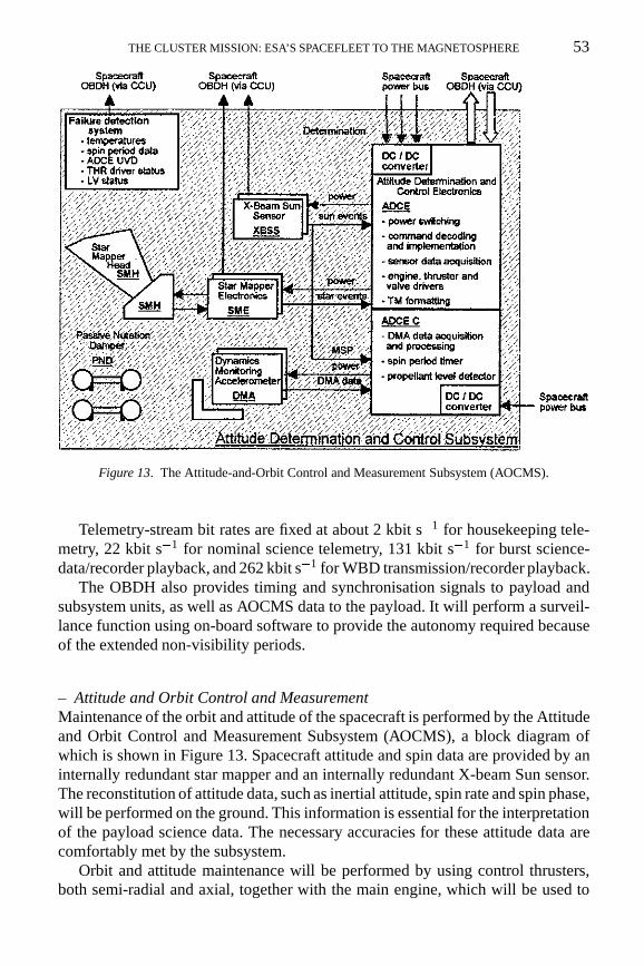
Figure 13. The Attitude-and-Orbit Control and Measurement Subsystem (AOCMS).
Telemetry-stream bit rates are fixed at about 2 kbit s�1 for housekeeping tele-metry, 22 kbit s�1 for nominal science telemetry, 131 kbit s�1 for burst science-data/recorder playback, and 262 kbit s�1 for WBD transmission/recorder playback.
The OBDH also provides timing and synchronisation signals to payload andsubsystem units, as well as AOCMS data to the payload. It will perform a surveil-lance function using on-board software to provide the autonomy required becauseof the extended non-visibility periods.
– Attitude and Orbit Control and MeasurementMaintenance of the orbit and attitude of the spacecraft is performed by the Attitudeand Orbit Control and Measurement Subsystem (AOCMS), a block diagram ofwhich is shown in Figure 13. Spacecraft attitude and spin data are provided by aninternally redundant star mapper and an internally redundant X-beam Sun sensor.The reconstitution of attitude data, such as inertial attitude, spin rate and spin phase,will be performed on the ground. This information is essential for the interpretationof the payload science data. The necessary accuracies for these attitude data arecomfortably met by the subsystem.
Orbit and attitude maintenance will be performed by using control thrusters,both semi-radial and axial, together with the main engine, which will be used to
54 J. CREDLAND ET AL.
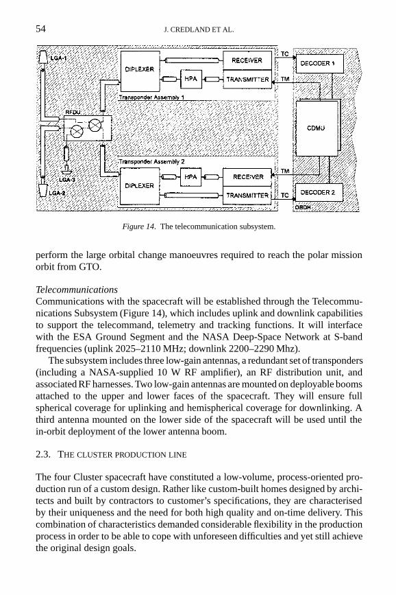
Figure 14. The telecommunication subsystem.
perform the large orbital change manoeuvres required to reach the polar missionorbit from GTO.
TelecommunicationsCommunications with the spacecraft will be established through the Telecommu-nications Subsystem (Figure 14), which includes uplink and downlink capabilitiesto support the telecommand, telemetry and tracking functions. It will interfacewith the ESA Ground Segment and the NASA Deep-Space Network at S-bandfrequencies (uplink 2025–2110 MHz; downlink 2200–2290 Mhz).
The subsystem includes three low-gain antennas, a redundant set of transponders(including a NASA-supplied 10 W RF amplifier), an RF distribution unit, andassociated RF harnesses. Two low-gain antennas are mounted on deployable boomsattached to the upper and lower faces of the spacecraft. They will ensure fullspherical coverage for uplinking and hemispherical coverage for downlinking. Athird antenna mounted on the lower side of the spacecraft will be used until thein-orbit deployment of the lower antenna boom.
2.3. THE CLUSTER PRODUCTION LINE
The four Cluster spacecraft have constituted a low-volume, process-oriented pro-duction run of a custom design. Rather like custom-built homes designed by archi-tects and built by contractors to customer’s specifications, they are characterisedby their uniqueness and the need for both high quality and on-time delivery. Thiscombination of characteristics demanded considerable flexibility in the productionprocess in order to be able to cope with unforeseen difficulties and yet still achievethe original design goals.
THE CLUSTER MISSION: ESA’S SPACEFLEET TO THE MAGNETOSPHERE 55
Whilst such characteristics also apply to other spacecraft programmes, thesituation with Cluster differed considerably in that the four flight models had tobe produced within the time normally allowed for one. Although Cluster was ofcourse not a series production in the full commercial sense, at system level it standssomewhere between the ‘one-off’ product of other scientific projects and the ‘massproduction’ in the telecommunications satellite sector, for example of satellites formobile services.
The picture changes completely at the unit and component levels: the hardwareof the four flight spacecraft alone is comprised of a total of about 360 units, 16rigid booms (without the 16 wire booms), 36 propellant tanks, 8 pressure tanks,32 thrusters, 320 m of RCS pipework, almost 17 km of harness, 1440 connectorsand more than 57 000 electrical contacts. Here, Cluster is indeed much closer to aseries production product.
A mixture of strategies originating from the two extremes of a ‘one-off’ and aseries production was therefore employed in the Cluster programme. ’Standardised’or ‘off-the-shelf’ items are typically used in mass production because they representreadily available identical units at reasonable cost. Such items have therefore beenused in many areas on Cluster; e.g. RCS equipment, silver-cadmium batteries,battery regulator units, sensors, booms and pressure tanks. Because such items areconsidered ‘flight-proven’ and usually have a long history of successful applicationin space, both development time and risk can be reduced by using them.
The designs of some ‘existing items’ like booms and battery regulator units hadto be slightly changed to cope with Cluster’s specific requirements, which requiredthe initiation of a full new space-qualification process. In other cases such as thepressure tanks, waivers against the Cluster requirements were granted after carefulevaluation of the item’s acceptability.
Parallel work flows are a typical mass-production technique for reducing overallproduction time. For Cluster, the modular design at system level allowed the parallelintegration of the RCS system with the central cylinder, and the various equipmentitems with the MEP. Mating of these two modules was performed after their pre-integration. Without this approach, the overall schedule could not have been met.
Parallel testing at unit and system level also became necessary to meet theoverall schedule. This situation was not ideal in that the first system-level testshad to be performed in parallel with the production of the next spacecraft model’sunits. Compromises between requirements and actual performances and betweenunit/subsystem and system verification became necessary, tending sometimes toincrease the risk. Further on, this situation resulted in extremely high workloads forlonger periods than usual for those involved simultaneously in the unit, subsystemand system activities.
The system-level testing periods were extremely long, embracing static load test-ing of the Structural Model/Spacecraft Mass Dummy (SM/SMD) stack, electricaltesting on the Engineering Model (EM), sine/random/acoustic vibration campaignson the SM/SMD stack, two sine/acoustic vibration campaigns for Flight Model
56 J. CREDLAND ET AL.
stacks, and thermal-balance/thermal-vacuum tests on each individual Flight Mod-el. Most of these tests were performed at IABG in Munich (D) between March1992 and March 1995, except for the period from mid- to end-1993 during whichthe EM tests took place at the Prime Contractor’s site. The electrical system-leveltests ran almost continuously on the various flight models.
While this situation presented logistic difficulties, the positive effect was thatthe various specialists worked with high efficiency because they could move almostimmediately from one spacecraft to the next. A pronounced learning-curve effectdue to repeated integration and testing activities also became visible at all levels,helping to achieve the prescribed overall schedule.
The flexibility during the production process that resulted from the production-line approach because more than one model per unit was available for much of thetime, provided more possibilities for work-arounds in the event of a failed unit.
The high motivation of all personnel involved in the activities was anotherprerequisite for success, allowing the timely solution of many unforeseen diffi-culties and problems. This included, for example, three-shift working at the PrimeContractor for an extended period during the early electrical-testing campaigns, tocompensate for unit delivery delays of up to six months.
The timely availability of hardware and software was of the utmost importanceto achieve the prescribed delivery date for the Cluster flight models.
Problems with long-lead-time items and some specific items like CMOS devices,hybrids, specific heaters, double foils for the thermal top and bottom shields, etc.had to be resolved. Sometimes only limited quantities of particular parts or materialswere available because of production stops in industry.
Traceability of the hardware and software has been another important elementin Cluster’s four-model programme. Each unit model has its own performancecharacteristics and its own calibration curves for the conversion of telemetry datainto meaningful physical measurements, with slight nuances occurring from onemodel to another. It was therefore important to keep track of which model of agiven unit was finally integrated to which spacecraft and in which position, not onlyfor the ground testing, but even more so for later in-orbit operations. Databasescontaining this information are therefore being continuously updated until launch.
Identical functioning of the four Cluster spacecraft is extremely important, asnoted earlier. This goal was achieved at unit level by applying common specificationlimits for all models of any given unit. Proof of specification compliance, and henceof ‘identicality’ between models, was provided by the individual unit acceptancetests.
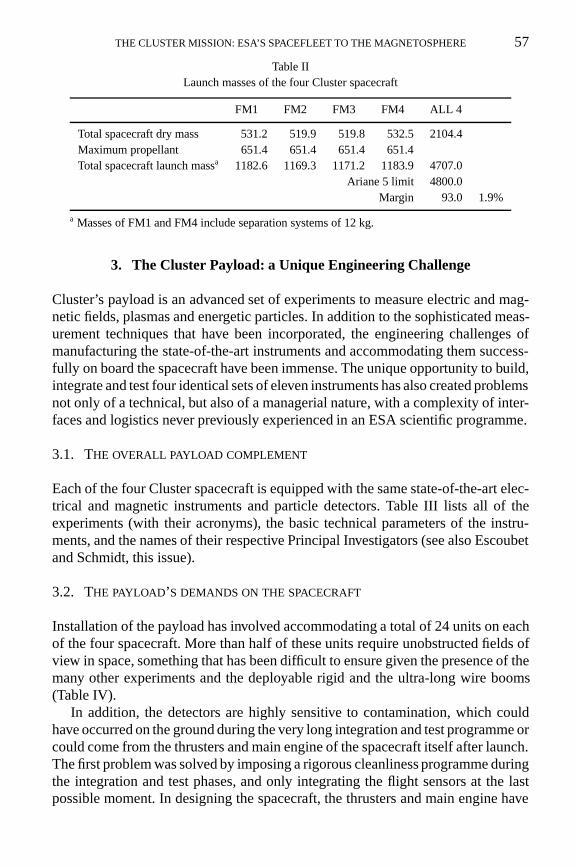
Identical functionality at system level could be checked via system-parametermeasurements on each of the Cluster flight models. Only a very small scatter wasfound between the four spacecraft models, as evident from the example of launchmasses given in Table II.
THE CLUSTER MISSION: ESA’S SPACEFLEET TO THE MAGNETOSPHERE 57
Table IILaunch masses of the four Cluster spacecraft
FM1 FM2 FM3 FM4 ALL 4
Total spacecraft dry mass 531.2 519.9 519.8 532.5 2104.4Maximum propellant 651.4 651.4 651.4 651.4Total spacecraft launch massa 1182.6 1169.3 1171.2 1183.9 4707.0
Ariane 5 limit 4800.0Margin 93.0 1.9%
a Masses of FM1 and FM4 include separation systems of 12 kg.
3. The Cluster Payload: a Unique Engineering Challenge
Cluster’s payload is an advanced set of experiments to measure electric and mag-netic fields, plasmas and energetic particles. In addition to the sophisticated meas-urement techniques that have been incorporated, the engineering challenges ofmanufacturing the state-of-the-art instruments and accommodating them success-fully on board the spacecraft have been immense. The unique opportunity to build,integrate and test four identical sets of eleven instruments has also created problemsnot only of a technical, but also of a managerial nature, with a complexity of inter-faces and logistics never previously experienced in an ESA scientific programme.
3.1. THE OVERALL PAYLOAD COMPLEMENT
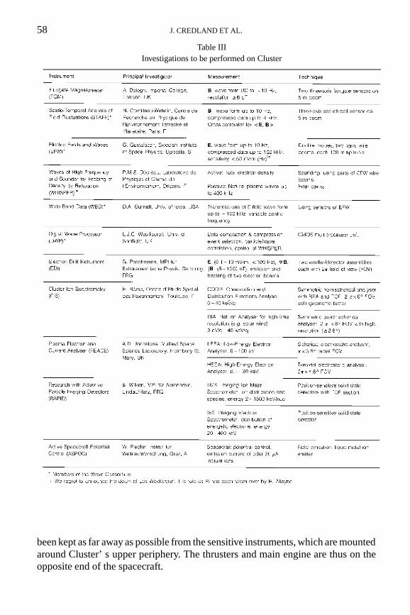
Each of the four Cluster spacecraft is equipped with the same state-of-the-art elec-trical and magnetic instruments and particle detectors. Table III lists all of theexperiments (with their acronyms), the basic technical parameters of the instru-ments, and the names of their respective Principal Investigators (see also Escoubetand Schmidt, this issue).
3.2. THE PAYLOAD’S DEMANDS ON THE SPACECRAFT
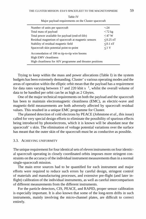
Installation of the payload has involved accommodating a total of 24 units on eachof the four spacecraft. More than half of these units require unobstructed fields ofview in space, something that has been difficult to ensure given the presence of themany other experiments and the deployable rigid and the ultra-long wire booms(Table IV).
In addition, the detectors are highly sensitive to contamination, which couldhave occurred on the ground during the very long integration and test programme orcould come from the thrusters and main engine of the spacecraft itself after launch.The first problem was solved by imposing a rigorous cleanliness programme duringthe integration and test phases, and only integrating the flight sensors at the lastpossible moment. In designing the spacecraft, the thrusters and main engine have
58 J. CREDLAND ET AL.
Table IIIInvestigations to be performed on Cluster
been kept as far away as possible from the sensitive instruments, which are mountedaround Cluster’ s upper periphery. The thrusters and main engine are thus on theopposite end of the spacecraft.
THE CLUSTER MISSION: ESA’S SPACEFLEET TO THE MAGNETOSPHERE 59
Table IVMajor payload requirements on the Cluster spacecraft
Number of units per spacecraft �24Total mass of payload �72 kgTotal power available for payload (end-of-life) �47 WResidual magnetism of spacecraft at magnetic sensors �0.25 nTStability of residual magnetic field �0.1 nTSpacecraft skin potential point-to-point �1 V
Accomodation of 100 m tip-to-tip wire boomsHigh EMV cleanlinessHigh cleanliness for AIV programme and thruster positions
Trying to keep within the mass and power allocations (Table I) in the systembudgets has been extremely demanding. Cluster’ s various operating modes and theareas of operation within the elliptic orbit mean that the payload has a requirementfor data rates varying between 17 and 220 kbit s�1, whilst the overall volume ofdata to be handled per orbit can be as high as 2 Gbytes.
One of the major technical requirements on both the payload and the spacecrafthas been to maintain electromagnetic cleanliness (EMC), as electric-wave andmagnetic-field measurements are both adversely affected by spacecraft residualvalues. This resulted in a unique EMC programme for Cluster.
The planned detection of cold electrons by PEACE (Johnstone et al., this issue)called for very special design efforts to eliminate the possibility of spurious effectsbeing introduced by photoelectrons, which it is known will be abundant near thespacecraft’ s skin. The elimination of voltage potential variations over the surfacehas meant that the outer skin of the spacecraft must be as conductive as possible.
3.3. ACHIEVING UNIFORMITY
The unique requirement for four identical sets of eleven instruments on four identic-al spacecraft operating in closely coordinated orbits imposes more stringent con-straints on the accuracy of the individual instrument measurements than in a normalsingle-spacecraft mission.
The main error sources had to be quantified for each instrument and majorefforts were required to reduce such errors by careful design, stringent controlof materials and manufacturing processes, and extensive pre-flight (and later in-flight) calibration of the individual instruments, as well as careful intercomparisonof different measurements from the different instruments.
For the particle detectors, CIS, PEACE, and RAPID, proper sensor calibrationis especially important. It is also known that some of the long-term drifts in suchinstruments, mainly involving the micro-channel plates, are difficult to correctentirely.
60 J. CREDLAND ET AL.
PEACE is a good example of how differences between the instruments on thefour spacecraft were assessed during the development programme. It is necessaryto maintain comparability between the analysers on the four flight spacecraft towithin 1%, including the in-flight intercalibration.
The PEACE analyser consists of two concentric hemispherical shells betweenwhich the electrons are deflected. In order to maintain the 1% goal, the concentricityof the hemispheres had to be maintained to better than 40 microns. When tested,the initial design was found to have a value of 150 microns. Even by improvingthe manufacturing tolerances to state-of-the-art values using specialist facilities, itcould only be reduced to 80 microns. A major redesign was therefore undertakenboth to increase the rigidity of the hemispheres and to connect them by a shorterload path using materials with similar coefficients of expansion (thereby reducingthe effects of minor temperature differences between detectors). By these means,and by using a Kapton instead of a ceramic anode and changing the mechanicaldesign, the tolerances could be reduced to 37 microns even using the normalflight-standard manufacturing tolerances.
For the wave experiments, the question of similarity on the four spacecraft wasnot a central issue. The stability of the oscillators is far better than the requiredfrequency resolution, which is mainly dictated by telemetry constraints. In orderto ensure correlation between measurements on the four spacecraft, the relativetiming between the measurements on each spacecraft is very important, which hasmeant that operational constraints have had to be rigorously defined.
The Fluxgate Magnetometer (FGM) requires an overall single instrument accur-acy of 0.1%. This has been demonstrated to be possible, and can also be checkedin orbit using a four-point intercalibration technique (DivB must always be zero).
3.4. OPTIMISATION OF RESOURCES
Payload resources were tight from the outset, with the baseline 72 kg/47 W/17 kbit s�1
already being oversubscribed at the proposal stage. A de-scoping and rationalisa-tion exercise had to take place immediately, which resulted in the formation ofthe Wave Experiment Consortium (WEC) and the provision of the power-supplyand data-handling functions via boxes common to all five of those experiments(Pedersen et al., this issue).
During the development phase, the payload mass again began to grow andevery additional gramme had to be accounted for. Very thin walled structures weredeveloped for some electronic boxes (e.g., FGM) and some instruments switchedto using magnesium as their primary structural material (e.g., WBD).
Power for driving the sophisticated instruments and their computers was alsocritical from an early stage. Various operating modes were therefore developedfor each instrument to conserve power by, for example, running the processorsat different speeds during the two-year mission. The data rates have also been
THE CLUSTER MISSION: ESA’S SPACEFLEET TO THE MAGNETOSPHERE 61
optimised by defining different operational modes and time-sharing between theindividual instruments.
The payloads to be launched on the flight spacecraft are still within their alloc-ated resources, thanks to the continual attention that has been paid to the problemby both the Experimenters and the ESA Project Team.
3.5. SURVIVING THE LAUNCH AND IN-ORBIT ENVIRONMENT
Before making any scientific measurements, Cluster’s instruments will have tosurvive the launch-induced vibrations. Once in orbit, they must work in an envir-onment varying between cold deep space and hot sunlight, and also endure aconstant shower of strong radiation.
The Cluster launch vibration environment has been assumed to be slightlyharsher than usual, to take into account the inherent uncertainties due to it beingthe first Ariane-5 launch. This has had design repercussions for some instrumentunits. The CIS experiment, for example, contains very thin carbon foils (densityof order 3 �g cm�2). It was very soon realised that these would have problemssurviving the vibration environment and so the experiment was mounted on rubberanti-vibration mounts. During testing, however, these foils still broke due to the highinduced displacements causing the foil to hit the surrounding structure. A designmodification and further testing has ensured that CIS will survive the launch.
The in-orbit thermal environment, varying from hot sunlight to long cold eclipseswith a minimum of heater power provided by the spacecraft, has presented a severechallenge for all protruding sensors. These need an environment close to roomtemperature for their sensitive components, like the micro-channel plates, whenoperating, and no colder than a freezer when non-operational.
A few sensors required further design optimisation after the spacecraft thermal-balance test. In particular, their coatings and thermal blanket interfaces had tobe changed. The thermal blankets are now ‘hand-tailored’ around the protrudinginstruments.
The predicted in-orbit radiation environment of 20 krad total dose that Clustermust endure has required the use of radiation-hardened or shielded components.Special circuitry to survive the latch-up that could be caused by particle intrusionhas also been necessary, especially for the CMOS technologies.
3.6. THE ELECTROMAGNETIC-CLEANLINESS PROBLEM
The instruments aboard each new generation of scientific satellite endeavour toexploit the latest sensor and electronic technology to achieve the highest possiblesensitivity and resolution. For a plasma mission like Cluster, this ideally meansthat the spacecraft itself should be ‘invisible’ , with no apparent interaction withthe space environment.
Reality is rather different; the spacecraft does become charged under the cyclicinfluence of sunlight and shadow. In addition, certain of the spacecraft’ s subsystems
62 J. CREDLAND ET AL.
contain relays and latch valves, which generate DC or slowly-varying magneticfields. It has an electrical support system for power and data-handling, which alsoconstitutes a source of electromagnetic interference. Last but not least, the scientificpayload itself may generate signals that could influence the performance of otherinstruments on board. Most of these phenomena are either impossible to simulate,or the levels involved are orders of magnitude too small to be measured on theground.
How then can a suitable spacecraft and its payload be built and tested to thesatisfaction of the scientific community? The process begins with a careful selectionof design concepts and materials, which are then translated into an electromagneticdesign and test specification. The necessary electrostatic cleanliness is achieved byusing a conductive coating on the spacecraft’s external surfaces, including the solararrays. Thermal insulation blankets and foils are coated with indium tin oxide and,along with all other external parts, locally grounded to the spacecraft structure toavoid the build-up of electrostatic potential. DC magnetic cleanliness imposes theselection of non-magnetic materials wherever possible. In addition, the magneticsensors are mounted on deployable booms, as far as possible from the spacecraftbody.
Electromagnetic interference is usually controlled by the synchronisation ofclock signals on-board the spacecraft. This, together with an optimised electricalharness configuration and grounding scheme, ensures minimum disturbance of thefrequency bands being observed by the scientific instruments.
However, when these design optimisations came to be translated into hardwarefor Cluster, some of the above concepts could not be realised: either the ideal tech-nology could not support the original purpose of a certain element or instrument,or it was not available within the given constraints of mass, power or schedule. AnEMC Review Board was therefore established, made up of scientists from eachparticular area of Cluster plasma science, from Industry and from ESA, to analysethe problems and to agree on acceptable solutions.
The verification phase involved various EMC analyses and tests, not only state-of-the-art conductivity and susceptibility tests, but also dedicated experiment testsfor the particularly sensitive WEC and PEACE instruments. After several iterationsand optimisation of the grounding schemes of these experiments and the spacecraftinterface, these two experiment teams were able to confirm a satifactorily lownoise environment on the spacecraft. Radiated emission and susceptibility testing atIABG in Munich, with the EFW wire booms partially deployed, finally confirmedthat the Cluster spacecraft generates levels very close to the instruments’ ownbackground noise.
In summary, the way to EMC cleanliness was not straightforward, but theclose cooperation of all parties involved in addressing the problem has resulted inCluster being one of the most electromagnetically clean spacecraft that ESA hasever launched.
THE CLUSTER MISSION: ESA’S SPACEFLEET TO THE MAGNETOSPHERE 63
3.7. SEVEN PCS ON EACH SPACECRAFT
A feature of modern-day instrumentation and the result of the great advances inmicrotechnology is the fact that each experiment has almost as much on-boardcomputational capability as the spacecraft’ s own on-board computer. In fact, theCluster payload has the processing capability of almost seven personal computers(PCs), the Wave Consortium being served by one processing unit (DWP).
This on-board computational power not only provides the interfaces with thespacecraft bus in terms of telemetry and telecommand handling, but also the inter-face with the various experiment units. It also performs a certain amount of on-boardscientific processing, which reduces the data rates needed to the ground.
The Digital Wave Processor (DWP), perhaps the most performant computer,consists of three T222 transputers, each with 32 kbytes of external RAM (internalmemory disabled to provide increased radiation tolerance) and 32 kbytes of PROM.DWP’s design permits the transputers to be operated at input clock frequencies of2.5 or 5 MHz, the slower rate requiring less power.
DWP ( Woolliscroft et al., this issue) performs two major software-driven tasks.The first is particle correlation, with a novel diagnostic technique based on formingauto-correlation functions of the time series of particle-detector counts as a functionof energy and pitch angle. Secondly, it performs data compression in order to copeoptimally with the restrictions on the available telemetry bandwidth. Various data-compression methods are implemented within the DWP to remove any redundantinformation from the data stream.
3.8. EXPERIMENT MANAGEMENT
Management of the Cluster experiments has provided some unique challenges forthe scientific community. To begin with, getting together the best payload suite inEurope to satisfy the mission requirements meant the involvement of 11 PrincipalInvestigators and interfacing with the Co-Investigators who will study the Clusterdata. This is not a unique scenario in terms of ESA missions, but it did mean thatrationalisation of the instrument groups was required early in the programme. Oneresult of this was the setting up of the WEC, mentioned earlier.
The next major problem was that, because the integration, testing and prepar-ation for launch of the four flight spacecraft would take place over two years,engineering breadboards were required very early in the programme compared tothe launch date. The experimenter groups performed this difficult task in a verysatisfactory way for the hardware, but the software for ground testing and on-boardprocessing always lagged behind.
For a nominal one-off spacecraft, once the flight hardware has been built andtested at the home institute, the payload team is available to assist the ESA projectteam with the system-level Assembly, Integration and Verification (AIV) pro-gramme. In Cluster’ s case, once the first flight instruments had been delivered,
64 J. CREDLAND ET AL.
another four (including flight spare) were needed. In addition, system-level testinghad to be performed simultaneously on up to three flight spacecraft (e.g. functionaltesting, EMC, and thermal vacuum), all of which required payload support. Theshort-term schedule for such system testing was also varying on a day-to-day basis.The logistical problems for the experimenter teams have therefore been immenseand a successful outcome hinged on the trust built up between the ESA project teamand the payload groups in the early days of the programme, and on the flexibilityshown by both sides. This has been supplemented by technological advances suchas the remote links established to both the integration and test sites (Dornier andIABG), which gave the payload teams remote access to their test data from theirhome institutes.
4. Conclusion
The engineering challenges faced with the Cluster mission have been some of themost demanding of any spacecraft ever launched. They have been faced together bya joint team of the ESA project, European Industry and the scientific community,resulting in the production of four near-identical spacecraft carrying an advancedplasma payload. Once launched, the intercalibration of the scientific payload willachieve the objective of having four near-identical instruments sets in orbit to per-form the first truly three-dimensional measurements of the Earth’s magnetosphericenvironment. The efforts of the combined team over the past eight years will ensurethat Cluster provides the worldwide scientific community with a wealth of data onthe magnetosphere which, when combined with data from other missions such asSOHO, Wind, Polar and Geotail, will form a unique data set on the Earth/Suninteraction.
References
Escoubet, C. P. and Schmidt, R.: 1996, ‘Cluster-Science and Mission Overview’, Space Sci. Rev., thisissue.
Ferri, P. and Warhaut, M.: 1996, ‘Cluster Mission Operations’, Space Sci. Rev., this issue.Johnstone, A. et al.: 1996, ‘PEACE: a Plasma Electron and Current Experiment’, Space Sci. Rev.,
this issue.Pedersen, A. et al.: 1996, ‘The Wave Experiment Consortium (WEC)’, Space Sci. Rev., this issue.Sørensen, E. M., Merri, M., and Di Girolamo, G.: 1996, ‘The Cluster Data Processing System: a
Distributed System in Support of a Challenging Mission’, Space Sci. Rev., this issue.Woolliscroft, L. J. C. et al.: 1996: ‘The Digital Wave-Processing Experiment on Cluster’, Space Sci.
Rev., this issue.