Embed Size (px)
Citation preview
1/56 Te
1
ContactorsF 3-pole contactors for motor control, 115 to 780 AUtilisation category AC-3Control circuit : a.c. or d.c.
References
3-pole contactors
Standard power ratings Rated operational Basic reference. (2) Weightof 3-phase motors current in AC-350/60 Hz in category AC-3
Screw fixing,220 V 380 V 660 V up to cabling230 V 400 V 415 V 440 V 500 V 690 V 1000 V 440 V (1)kW kW kW kW kW kW kW A kg
30 55 59 59 75 80 65 115 LC1-F115 3.43040 75 80 80 90 100 65 150 LC1-F150 3.43055 90 100 100 110 110 100 185 LC1-F185 4.65063 110 110 110 129 129 100 225 LC1-F225 4.75075 132 140 140 160 160 147 265 LC1-F265 7.440100 160 180 200 200 220 160 330 LC1-F330 8.600110 200 220 250 257 280 185 400 LC1-F400 9.100147 250 280 295 355 335 335 500 LC1-F500 11.350200 335 375 400 400 450 450 630 LC1-F630 18.600220 400 425 425 450 475 450 780 LC1-F780 39.500Note : auxiliary contact blocks and modules : see pages 1/66 and 1/67.(1) Up to rating LC1-F630, power terminals may be protected by the addition of shrouds, to be orderedseparately (see page 1/69).(2) Coils to be ordered separately :
– a.c. supply, see pages 1/72 and 1/73 – d.c. supply, see pages 1/74 and 1/75.
Other versions Please consult your Regional customer centre.
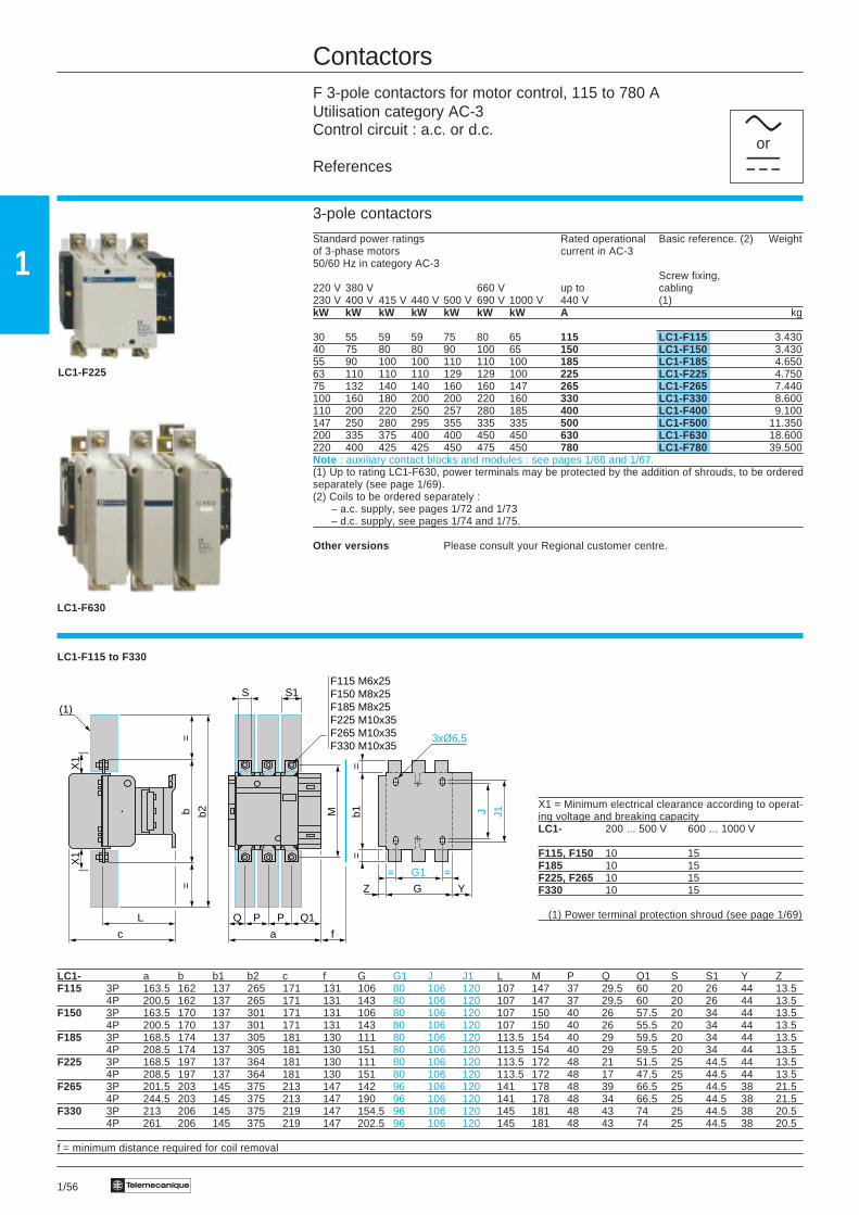
LC1-F115 to F330
X1 = Minimum electrical clearance according to operat-ing voltage and breaking capacityLC1- 200 ... 500 V 600 ... 1000 V
F115, F150 10 15F185 10 15F225, F265 10 15F330 10 15
(1) Power terminal protection shroud (see page 1/69)
LC1- a b b1 b2 c f G G1 J J1 L M P Q Q1 S S1 Y ZF115 3P 163.5 162 137 265 171 131 106 80 106 120 107 147 37 29.5 60 20 26 44 13.5
4P 200.5 162 137 265 171 131 143 80 106 120 107 147 37 29.5 60 20 26 44 13.5F150 3P 163.5 170 137 301 171 131 106 80 106 120 107 150 40 26 57.5 20 34 44 13.5
4P 200.5 170 137 301 171 131 143 80 106 120 107 150 40 26 55.5 20 34 44 13.5F185 3P 168.5 174 137 305 181 130 111 80 106 120 113.5 154 40 29 59.5 20 34 44 13.5
4P 208.5 174 137 305 181 130 151 80 106 120 113.5 154 40 29 59.5 20 34 44 13.5F225 3P 168.5 197 137 364 181 130 111 80 106 120 113.5 172 48 21 51.5 25 44.5 44 13.5
4P 208.5 197 137 364 181 130 151 80 106 120 113.5 172 48 17 47.5 25 44.5 44 13.5F265 3P 201.5 203 145 375 213 147 142 96 106 120 141 178 48 39 66.5 25 44.5 38 21.5
4P 244.5 203 145 375 213 147 190 96 106 120 141 178 48 34 66.5 25 44.5 38 21.5F330 3P 213 206 145 375 219 147 154.5 96 106 120 145 181 48 43 74 25 44.5 38 20.5
4P 261 206 145 375 219 147 202.5 96 106 120 145 181 48 43 74 25 44.5 38 20.5
f = minimum distance required for coil removal
LC1-F630
LC1-F225
cora
J J1b1=
=
G1
GZ
= =
Y
3xØ6,5
L
c
(1)
=b
=
b2
X1
X1
S1
Q
a
P P Q1
f
M
SF115 M6x25F150 M8x25F185 M8x25F225 M10x35F265 M10x35F330 M10x35
1/57Te
1
ContactorsF contactors for heating, lighting, etc., 200 to 1600 AUtilisation category AC-1Control circuit : a.c. or d.c.
References
2, 3 and 4-pole contactors
Maximum Number Basic reference. (2) Weightcurrent of polesin AC-1(θ ≤ 40 °C) Screw fixing,
cabling(1)
A kg
200 3 LC1-F115 3.4304 LC1-F1154 3.830
250 3 LC1-F150 3.4304 LC1-F1504 3.830
275 3 LC1-F185 4.6504 LC1-F1854 5.450
315 3 LC1-F225 4.7504 LC1-F2254 5.550
350 3 LC1-F265 7.4404 LC1-F2654 8.540
400 3 LC1-F330 8.6004 LC1-F3304 9.500
500 2 LC1-F4002 8.0003 LC1-F400 9.1004 LC1-F4004 10.200
700 2 LC1-F5002 9.7503 LC1-F500 11.3504 LC1-F5004 12.950
1000 2 LC1-F6302 15.5003 LC1-F630 18.6004 LC1-F6304 21.500
1600 3 LC1-F780 39.5004 LC1-F7804 48.000
Note : auxiliary contact blocks and modules : see pages 1/66 and 1/67.(1) Up to rating LC1-F630, power terminals may be protected by the addition of shrouds, to be orderedseparately (see page 1/69).(2) Coils to be ordered separately :
– a.c. supply, see pages 1/72 and 1/73 – d.c. supply, see pages 1/74 and 1/75.
Other versions Please consult your Regional customer centre.
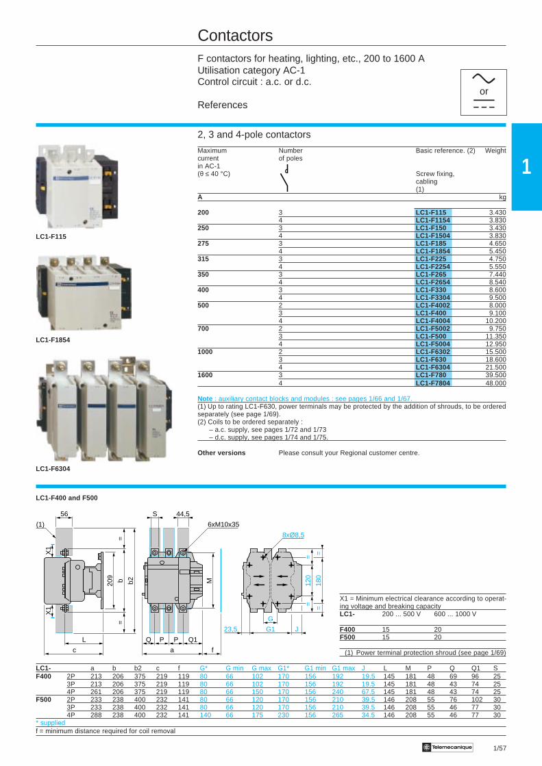
LC1-F400 and F500
X1 = Minimum electrical clearance according to operat-ing voltage and breaking capacityLC1- 200 ... 500 V 600 ... 1000 V
F400 15 20F500 15 20
(1) Power terminal protection shroud (see page 1/69)
LC1- a b b2 c f G* G min G max G1* G1 min G1 max J L M P Q Q1 SF400 2P 213 206 375 219 119 80 66 102 170 156 192 19.5 145 181 48 69 96 25
3P 213 206 375 219 119 80 66 102 170 156 192 19.5 145 181 48 43 74 254P 261 206 375 219 119 80 66 150 170 156 240 67.5 145 181 48 43 74 25
F500 2P 233 238 400 232 141 80 66 120 170 156 210 39.5 146 208 55 76 102 303P 233 238 400 232 141 80 66 120 170 156 210 39.5 146 208 55 46 77 304P 288 238 400 232 141 140 66 175 230 156 265 34.5 146 208 55 46 77 30
* suppliedf = minimum distance required for coil removal
LC1-F1854
cora
LC1-F6304
G
G123,5 J
120
==
180
==
8xØ8,5
L
c
=b
=
b2209
56
(1)
X1
X1
Q1
a
PQ P
f
M
44,5S
6xM10x35
LC1-F115
1/58 Te
1
180
==
J1G60,5
4xØ10,5
Q1
a
8080Q
264
181 (2)
6440
6xM12x45
155
=30
4=
(1)
197
255
280
X1
464
72
X1
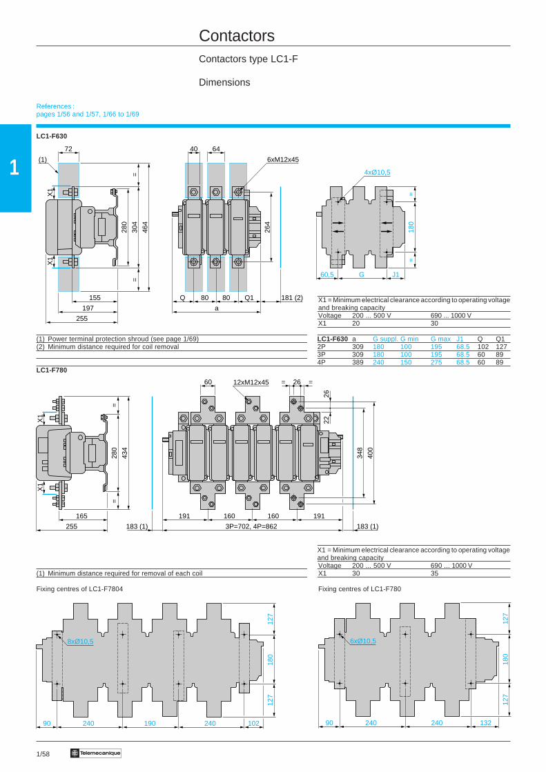
ContactorsContactors type LC1-F
Dimensions
LC1-F630
X1 = Minimum electrical clearance according to operating voltageand breaking capacityVoltage 200 ... 500 V 690 ... 1000 VX1 20 30
(1) Power terminal protection shroud (see page 1/69) LC1-F630 a G suppl. G min G max J1 Q Q1(2) Minimum distance required for coil removal 2P 309 180 100 195 68.5 102 127
3P 309 180 100 195 68.5 60 894P 389 240 150 275 68.5 60 89
LC1-F780
X1 = Minimum electrical clearance according to operating voltageand breaking capacityVoltage 200 ... 500 V 690 ... 1000 V
(1) Minimum distance required for removal of each coil X1 30 35
Fixing centres of LC1-F7804 Fixing centres of LC1-F780
10224090 190 240
180
127
127
8xØ10,5
13224090 240
180
127
127
6xØ10,5
191
183 (1)
191160 160
183 (1)
60 12xM12x45 26= =
348
400
2226
3P=702, 4P=862
X1
X1
=28
0=
434
165
255
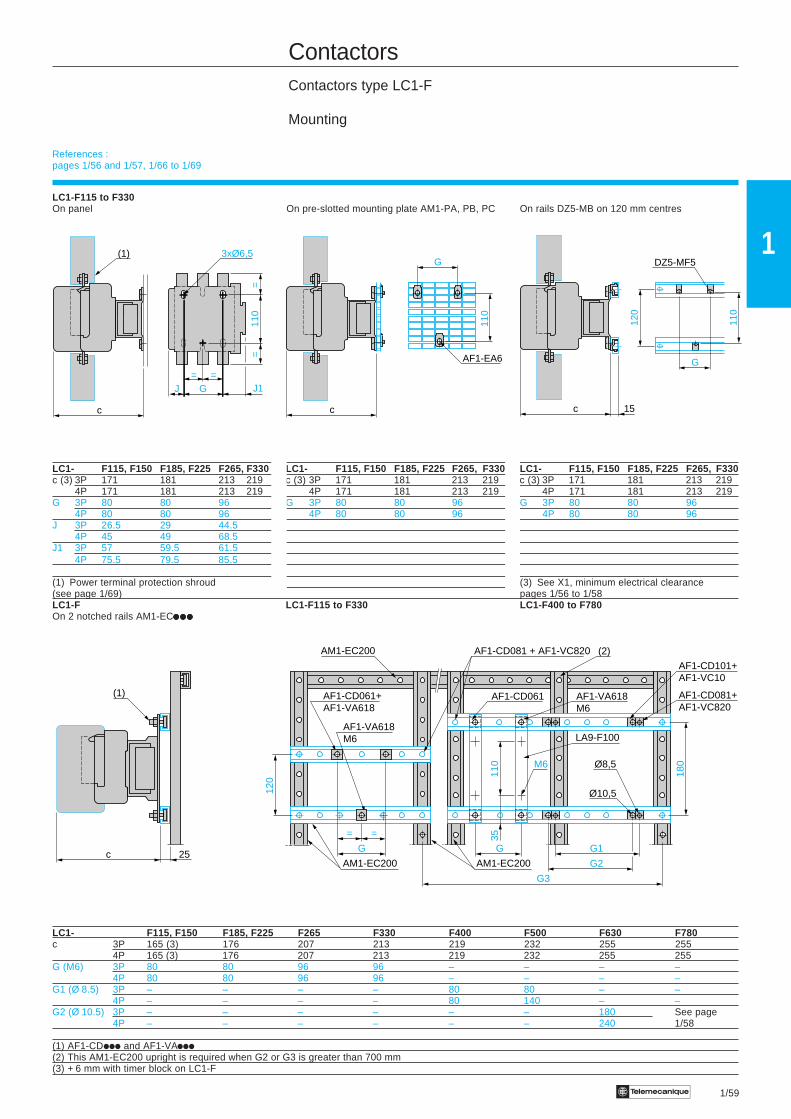
References :pages 1/56 and 1/57, 1/66 to 1/69
1/59Te
1
ContactorsContactors type LC1-F
Mounting
LC1-F115 to F330On panel On pre-slotted mounting plate AM1-PA, PB, PC On rails DZ5-MB on 120 mm centres
LC1- F115, F150 F185, F225 F265, F330 LC1- F115, F150 F185, F225 F265, F330 LC1- F115, F150 F185, F225 F265, F330c (3) 3P 171 181 213 219 c (3) 3P 171 181 213 219 c (3) 3P 171 181 213 219
4P 171 181 213 219 4P 171 181 213 219 4P 171 181 213 219G 3P 80 80 96 G 3P 80 80 96 G 3P 80 80 96
4P 80 80 96 4P 80 80 96 4P 80 80 96J 3P 26.5 29 44.5
4P 45 49 68.5J1 3P 57 59.5 61.5
4P 75.5 79.5 85.5
(1) Power terminal protection shroud (3) See X1, minimum electrical clearance(see page 1/69) pages 1/56 to 1/58LC1-F LC1-F115 to F330 LC1-F400 to F780On 2 notched rails AM1-ECiiiiiiiiiiiiiii
LC1- F115, F150 F185, F225 F265 F330 F400 F500 F630 F780c 3P 165 (3) 176 207 213 219 232 255 255
4P 165 (3) 176 207 213 219 232 255 255G (M6) 3P 80 80 96 96 – – – –
4P 80 80 96 96 – – – –G1 (Ø 8.5) 3P – – – – 80 80 – –
4P – – – – 80 140 – –G2 (Ø 10.5) 3P – – – – – – 180 See page
4P – – – – – – 240 1/58
(1) AF1-CDiii and AF1-VAiii(2) This AM1-EC200 upright is required when G2 or G3 is greater than 700 mm(3) + 6 mm with timer block on LC1-F
3xØ6,5
c
J G=
J1
=
110
=
=(1)
c
AF1-EA6
110
G DZ5-MF5
c
G
110
120
15
c 25
(1)
120
(2)
Ø10,5
AM1-EC200 AF1-CD081 + AF1-VC820
AM1-EC200
AF1-CD061+AF1-VA618
AF1-CD061 AF1-VA618M6
LA9-F100
AF1-CD101+AF1-VC10
AF1-CD081+AF1-VC820
Ø8,5M6
AM1-EC200
110
35
180
G
= =
G
AF1-VA618M6
G1
G2
G3
References :pages 1/56 and 1/57, 1/66 to 1/69
1/60 Te
1
ContactorsF 3-pole reversing contactors for motor control, 115 to 265 AUtilisation category AC-3Assembled by Telemecanique
References
3-pole reversing contactors (horizontally mounted) (1)
Pre-wired power connectionsStandard power ratings Opera- Maximum Contactors supplied Weightof 3-phase motors tional operational without coil (2)50/60 Hz in category AC-3 current voltage
in AC-3220 V 380 V 660 V up to230 V 400 V 415 V 440 V 500 V 690 V 1000 V 440 VkW kW kW kW kW kW kW A V kg
30 55 59 59 75 80 65 115 1000 LC2-F115 7.56040 75 80 80 90 100 65 150 1000 LC2-F150 7.56055 90 100 100 110 110 100 185 1000 LC2-F185 10.10063 110 110 110 129 129 100 225 1000 LC2-F225 14.20075 132 140 140 160 160 147 265 1000 LC2-F265 16.480
Accessories (to be ordered separately)
Description For Number Reference Weightreversing contactors required kg
Power terminal LC2-F115 2 LA9-F701 0.250protection shrouds LC2-F150, F185 2 LA9-F702 0.250
LC2-F225, F265 2 LA9-F703 0.250Auxiliary contact blocks and add-on modules See pages 1/66 to 1/68(1) Fitted with mechanical interlock without electrical interlocking. Order separately 2 auxiliary contactblocks LA1-DNi1 to obtain electrical interlocking between the 2 contactors, see page 1/67. For theaccessories, see pages 1/68 to 1/71.(2) Coils to be ordered separately :
- a.c. supply, see pages 1/72 and 1/73.- d.c. supply, see page 1/75.
Power terminals can be protected against direct finger contact by the addition of shrouds, to be orderedseparately, see above.
Assembled by TelemecaniqueLC2-F115 to F265 (reverser supplied on 2 bars which can be used for fixing the device)
f - Minimum distance required for coil removal.
X1 = Minimum electrical clearance according to operational voltage and breaking capacity Bar fixing centres :LC1- 200…500 V 660…1000 V vertical : 120 mm.F115, F150 10 15 horizontal : a2 see tableF185 10 15F225, F265 10 15
LC2- a a2 b b1 b2 c c1 G1 J J1 L M P P1 Q1 S S1 f ØF115 3P 345 317 162 137 265 171 130 80 71 57 107 147 37 77 60 20 26 131 M6
4P 419 378 162 137 265 171 130 80 108 75.5 107 147 37 77 60 20 26 131 M6F150 3P 345 317 170 137 301 171 133.5 80 71 57 107 150 40 71 57 20 34 131 M8
4P 422 381 170 137 301 171 133.5 80 111 75.5 107 150 40 71 55.5 20 34 131 M8F185 3P 357 326 174 137 305 181 140 80 78 59.5 113.5 154 40 78 59.5 20 34 130 M8
4P 437 390 174 137 305 181 140 80 118 79.5 113.5 154 40 78 59.5 20 34 130 M8F225 3P 357 326 197 137 364 181 148.5 80 78 59.5 113.5 172 48 62 51.5 25 44.5 130 M10
4P 437 390 197 137 364 181 148.5 80 118 79.5 113.5 172 48 54 47.5 25 44.5 130 M10F265 3P 425 386 203 145 375 213 175 96 109 61.5 141 178 48 100 66.5 25 44.5 147 M10
4P 521 464 203 145 375 213 175 96 157 85.5 141 178 48 100 66.5 25 44.5 147 M10(1) Power terminal protection shroud.
caor
110/
120
==
=
G1 J1
3xØ6,5
120
==
G1
a2
=
J1 J
3xØ6,5
3xØ6,5
3xØ6,5
L
c
(1)
=b
=
b2b1
c1
X1
X1
S1
P1
a
P P Q1
f
M
S
f
P PQ1
Ø

1/61Te
1
ContactorsF 4-pole changeover contactor pairs for distribution circuits, etc.Utilisation category AC-1Assembled by Telemecanique
References
4-pole changeover contactor pairs (horizontally mounted) (1)
Pre-wired power connectionsUtilisation category AC-1 Maximum Contactors supplied WeightNon inductive loads operational without coil (2)Maximum operational current voltageθ < 40 °CA V kg
200 1000 LC2-F1154 8.860250 1000 LC2-F1504 8.860275 1000 LC2-F1854 12.100315 1000 LC2-F2254 15.200350 1000 LC2-F2654 19.480
Accessories (to be ordered separately)
Description For Number Reference Weightchangeover pairs required kg
Power terminal LC2-F1154 2 LA9-F706 0.250protection shrouds LC2-F1504, F1854 2 LA9-F707 0.250
LC2-F2254, F2654 2 LA9-F708 0.250
Auxiliary contact blocks See pages 1/66 to 1/68(1) Fitted with mechanical interlock without electrical interlocking. Order separately 2 auxiliary contactblocks LA1-DNi1 to obtain electrical interlocking between the 2 contactors, see page 1/67. For theaccessories, see pages 1/68 to 1/71.(2) Coils to be ordered separately :
- a.c. supply, see pages 1/72 and 1/73.- d.c. supply, see page 1/75.
Power terminals can be protected against direct finger contact by the addition of shrouds, to be orderedseparately, see above.
For customer assembly, with mechanical interlock (MI) LA9-Fiiiiiiiiiiiiiii, fixing recommended on AM1-ECiiiiiiiiiiiiiii uprights.2 x LC1 identical or different ratings (LC1-F115 to F630) . See pages 1/62 to 1/65.Assembly A Assembly B Assembly C
(1) Mechanical interlock shaft. (3) 4 x Ø6.5 for LC1-F115 to F225(2) For assembly of contactors of different ratings only. (4) 4 x Ø6.5 for LC1-F265 (6) 4 x Ø8.5 for LC1-F400, F500 or
(5) Mechanical interlock guide bracket 4 x Ø10.5 for LC1-F630
120
120
H1
80J4
J2
J1G3(2)
= =
(3)
= =
(3)
80J3
H
(1)
(1)
= =
F33
0F
265
180
H1
120
F
400
F50
0F
630
180
G1G512,5
J1G3(2)
80J4
(3)
= =
(6)
(4)
H
(1)
(1)
9
(5)
J2
F33
0F
265
H1
120
F
400
F50
0F
630
180
F33
0F
265
120
F
400
F50
0F
630
180
J1G3(2)
(6)
G2G4
J2
12,59
= =
(4)
(6)
G1G512,5
H
(1)
(5)
(1)(5)
caor
1/62 Te
1
ContactorsReversing contactors and changeover contactor pairs LC2-FComponents for assembling 3-pole reversing contactorsand changeover contactor pairs, for customer assembly
References
Horizontally mounted Mechanical interlocks Sets of power connections
Reversers assembled Reversing contactors 3-pole changeover contactorusing 2 contactors of pairs (1)identical rating, type : LA9-Fi970 LA9-Fiii76 LA9-Fiii82LC1-F115LC1-F150LC1-F185LC1-F225LC1-F265LC1-F330LC1-F400LC1-F500LC1-F630
Vertically mounted Mechanical interlocks
Reversers assembled LA9-FF4F LA9-FH4Husing 2 contactors of LA9-FG4G LA9-FJ4Jidentical rating, type : LA9-FK4KLC1-F115 LA9-FL4LLC1-F150LC1-F185LC1-F225LC1-F265LC1-F330LC1-F400LC1-F500LC1-F630
LC1-F780 LA9-FX970
(1) For 4-pole changeover contactor pairs, see pages 1/64 and 1/65.
A1
A1
A2
A2
12
34
56
12
34
56
L1 L2 L3
U V W
A2
A2
A1
A11
2
34
56
34
56
1/L3
1/L2
1/L1
L2
12
L12/
L1
2/L2
2/L3
L3
1/63Te
1
ContactorsReversing contactors and changeover contactor pairs LC2-FComponents for assembling 3-pole reversing contactorsand changeover contactor pairs, for customer assembly
References
Reversers and changeover contactor pairs assembled using 2 contactorsof identical rating
Contactor Set of power connections Mechanical interlocktype Reference Weight Kit reference Weight(1) kg kg
For assembly of 3-pole reversing contactors for motor control
Horizontally mounted
LC1-F115 LA9-FF976 0.600 LA9-FF970 0.060LC1-F150 LA9-F15076 0.600 LA9-FF970 0.060LC1-F185 LA9-FG976 0.780 LA9-FG970 0.060LC1-F225 LA9-F22576 1.500 LA9-FG970 0.060LC1-F265 LA9-FH976 1.500 LA9-FJ970 0.140LC1-F330 LA9-FJ976 2.100 LA9-FJ970 0.140LC1-F400 LA9-FJ976 2.100 LA9-FJ970 0.140LC1-F500 LA9-FK976 2.350 LA9-FJ970 0.140LC1-F630 LA9-FL976 3.800 LA9-FL970 0.150
Vertically mounted
LC1-F115 or F150 (2) – LA9-FF4F 0.345LC1-F185 (2) – LA9-FG4G 0.350LC1-F225 (2) – LA9-FG4G 0.350LC1-F265 (2) – LA9-FH4H 1.060LC1-F330 (2) – LA9-FJ4J 1.200LC1-F400 (2) – LA9-FJ4J 1.200LC1-F500 (2) – LA9-FK4K 1.200LC1-F630 (2) – LA9-FL4L 1.220LC1-F780 (3) – LA9-FX970 (3) 6.100
For assembly of 3-pole changeover contactor pairs (4)
Horizontally mounted
LC1-F115 LA9-FF982 0.460 LA9-FF970 0.060LC1-F150 LA9-F15082 0.460 LA9-FF970 0.060LC1-F185 LA9-FG982 0.610 LA9-FG970 0.060LC1-F225 LA9-F22582 1.200 LA9-FG970 0.060LC1-F265 LA9-FH982 1.200 LA9-FJ970 0.140LC1-F330 LA9-FJ982 1.800 LA9-FJ970 0.140LC1-F400 LA9-FJ982 1.800 LA9-FJ970 0.140LC1-F500 LA9-FK982 2.300 LA9-FJ970 0.140LC1-F630 LA9-FL982 3.400 LA9-FL970 0.150
Vertically mounted
LC1-F115 or F150 (2) – LA9-FF4F 0.345LC1-F185 (2) – LA9-FG4G 0.350LC1-F225 (2) – LA9-FG4G 0.350LC1-F265 (2) – LA9-FH4H 1.060LC1-F330 (2) – LA9-FJ4J 1.200LC1-F400 (2) – LA9-FJ4J 1.200LC1-F500 (2) – LA9-FK4K 1.200LC1-F630 (2) – LA9-FL4L 1.220LC1-F780 (5) – LA9-FX971 (5) 7.800(1) To order the 2 contactors : see pages 1/56 and 1/57. Order 2 contact blocks LA1-DNi1 to obtainelectrical interlocking between the 2 contactors : see page 1/67.(2) All power connections are to be made by the customer, except for contactors type LC1-F780.(3) Double mechanical interlock mechanism with 2 interlock connecting rods and 3 power connectinglinks.(4) For assembly of 4-pole changeover contactor pairs, see pages 1/64 and 1/65.(5) Double mechanical interlock mechanism with 2 interlock connecting rods and 4 power connectinglinks.
caor

1/64 Te
1
ContactorsReversing contactors and changeover contactor pairs LC2-FComponents for assembling 3 and 4-pole reversing contactorsand changeover contactor pairs, for customer assembly
References
Horizontally mounted Mechanical interlocks Sets of power connections
Changeover pairs 4-pole changeoverassembled using contactor pairs (1)2 contactors of LA9-Fi970 LA9-Fiii77identical rating, type :LC1-F1154LC1-F1504LC1-F1854LC1-F2254LC1-F2654LC1-F3304LC1-F4004LC1-F5304LC1-F6304
Vertically mounted Mechanical interlocks
Changeover pairs LA9-FF4F LA9-FH4H LA9-FX971assembled using LA9-FG4G LA9-FJ4J2 contactors of LA9-FK4Kidentical rating, type : LA9-FL4LLC1-F1154LC1-F1504LC1-F1854LC1-F2254LC1-F2654LC1-F3304LC1-F4004LC1-F5004LC1-F6304
Reversers and changeover LA9-FG4F LA9-FH4F LA9-FJ4Hcontactor pairs assembled LA9-FJ4F LA9-FK4Husing 2 contactors of LA9-FK4F LA9-FL4Kdifferent ratings, type : LA9-FL4F LA9-FK4JLC1-F115 or F1154 LA9-FH4G LA9-FL4JLC1-F150 or F1504 LA9-FJ4G LA9-FL4KLC1-F185 or F1854 LA9-FK4GLC1-F225 or F2254 LA9-FL4GLC1-F265 or F2654LC1-F330 or F3304LC1-F400 or F4004LC1-F500 or F5004LC1-F630 or F6304
Reversers and changeover LA9-Fiiiii4iiiii4iiiii : please consult your Regional customer centre.contactor pairs assembledusing 3 contactors of identicalor different ratings, type :LC1-F115 or F1154LC1-F150 or F1504LC1-F185 or F1854LC1-F225 or F2254LC1-F265 or F2654LC1-F330 or F3304LC1-F400 or F4004LC1-F500 or F5004LC1-F630 or F6304
Warning : the contactor ratings must be in decreasing size from top to bottom.(1) For 3-pole changeover contactor pairs, see pages 1/62 and 1/63.
A1
A2
A1
A2
12
34
56
34
56
78
1N
1/L3
1/L2
L2
12
L1
78
1/L1
2/L1
2/L2
2/L3 2N
L3 N
1/65Te
1
ContactorsReversing contactors and changeover contactor pairs LC2-FComponents for assembling 3 and 4-pole reversing contactorsand changeover contactor pairs, for customer assembly
References
Changeover contactor pairs assembled using 2 contactors of identical rating
For assembly of 4-pole changeover contactor pairs (2)Contactor Set of power connections Mechanical interlocktype Reference Weight Kit reference Weight(1) kg kg
Horizontally mounted
LC1-F1154 LA9-FF977 0.460 LA9-FF970 0.060LC1-F1504 LA9-F15077 0.460 LA9-FF970 0.060LC1-F1854 LA9-FG977 0.610 LA9-FG970 0.060LC1-F2254 LA9-F22577 1.200 LA9-FG970 0.060LC1-F2654 LA9-FH977 1.200 LA9-FJ970 0.140LC1-F3304 LA9-FJ977 1.800 LA9-FJ970 0.140LC1-F4004 LA9-FJ977 1.800 LA9-FJ970 0.140LC1-F5004 LA9-FK977 2.300 LA9-FJ970 0.140LC1-F6304 LA9-FL977 3.400 LA9-FL970 0.150
Vertically mounted
LC1-F1154 or F1504 (3) – LA9-FF4F 0.345LC1-F1854 (3) – LA9-FG4G 0.350LC1-F2254 (3) – LA9-FG4G 0.350LC1-F2654 (3) – LA9-FH4H 1.060LC1-F3304 (3) – LA9-FJ4J 1.200LC1-F4004 (3) – LA9-FJ4J 1.200LC1-F5004 (3) – LA9-FK4K 1.200LC1-F6304 (3) – LA9-FL4L 1.220LC1-F7804 (4) – LA9-FX971 (4) 7.800
Changeover contactor pairs assembled using 2 contactors of different ratings
For assembly of 3 or 4-pole changeover contactor pairsContactor Set of power connections Mechanical interlocktype Reference Kit reference Weight(5) kg
Vertically mounted
at bottom at top
LC1-F115 or F1154 LC1-F185 or F1854 LA9-FG4F 0.350or LC1-F225 or F2254 LA9-FG4F 0.350LC1-F150 or F1504 LC1-F265 or F2654 LA9-FH4F 0.870
LC1-F330 or F3304 LA9-FJ4F 0.930LC1-F400 or F4004 LA9-FJ4F 0.930LC1-F500 or F5004 LA9-FK4F 0.940LC1-F630 or F6304 LA9-FL4F 0.940
LC1-F185 or F1854 LC1-F265 or F2654 LA9-FH4G 0.860or LC1-F330 or F3304 LA9-FJ4G 0.940LC1-F225 or F2254 LC1-F400 or F4004 LA9-FJ4G 0.940
LC1-F500 or F5004 LA9-FK4G 0.940LC1-F630 or F6304 LA9-FL4G 0.950
LC1-F265 or F2654 LC1-F400 or F4004 LA9-FJ4H 1.130or LC1-F500 or F5004 LA9-FK4H 1.130LC1-F330 or F3304 LC1-F630 or F6304 LA9-FL4H 1.140
LC1-F400 or F4004 LC1-F500 or F5004 LA9-FK4J 1.200LC1-F630 or F6304 LA9-FL4J 1.210
LC1-F500 or F5004 LC1-F630 or F6304 LA9-FL4K 1.210
For assembly of reversers using 3 contactors, vertically mounted (please consult our specialisedcatalogue)
(1) To order the 2 contactors : see pages 1/56 and 1/57. Order 2 contact blocks LA1-DNi1 to obtainelectrical interlocking between the 2 contactors, see page 1/67.(2) For assembly of 3-pole changeover contactor pairs, see pages 1/62 and 1/63.(3) All power connections are to be made by the customer.(4) Double mechanical interlock with 2 interlock connecting rods and 4 power connecting links.(5) Contactors with identical or different number of poles. To order the 2 contactors, see pages 1/56 and1/57. Order 2 contact blocks LA1-DNi1 to obtain electrical interlocking between the 2 contactors, seepage 1/67.
caor
Dimensions :page 1/60
1/66 Te
1
LA1-DX, DY, DZ
LA3-DR
LA2-DT, DS
LA1-DN, DC
LA1-DN
LC1-FLA1-DN10, DN01
1/67Te
1
ContactorsContactors and reversing contactors type LC1-F and LC2-FAuxiliary contact blocks and time delay auxiliary contacts
References
Instantaneous auxiliary contact blocks
For use in normal operating environmentsNumber Max. number of blocks per contactor Composition Reference Weightof Side clip-on mountingcontacts
kg
1 1 – – 1 – LA1-DN10 0.020– – – 1 LA1-DN01 0.020
2 2 – – 1 1 LA1-DN11 0.030– – 2 – LA1-DN20 0.030– – – 2 LA1-DN02 0.030
4 2 – – 2 2 LA1-DN22 0.050– – 1 3 LA1-DN13 0.050– – 4 – LA1-DN40 0.050– – – 4 LA1-DN04 0.050– – 3 1 LA1-DN31 0.050– – 2 2 (1) LA1-DC22 0.050
With selected terminal referencing conforming to standard EN 50012
2 2 – – 1 1 LA1-DN11M 0.030– – 1 1 LA1-DN11P 0.030– – 1 1 LA1-DN11G 0.030
4 2 – – 2 2 LA1-DN22M 0.050– – 2 2 LA1-DN22P 0.050– – 2 2 LA1-DN22G 0.050
Instantaneous auxiliary contact blocks with dust and damp protected contacts
For use in harsh industrial environmentsNumber Max. number of blocks per contactor Composition Reference Weightof Side clip-on mountingcontacts
kg
2 2 2 – – – LA1-DX20 0.0402 2 (2) – – LA1-DY20 0.040
4 2 2 – 2 – LA1-DZ40 0.0502 – 1 1 LA1-DZ31 0.050
Time delay auxiliary contacts
Number Max. number of blocks per contactor Time delay Reference Weightof Side clip-on mounting Type Rangecontacts (s) kg
1 N/O 2 On-delay 0.1…3 (3) LA2-DT0 0.060+ 0.1…30 LA2-DT2 0.0601 N/C 10…180 LA2-DT4 0.060
1…30 (4) LA2-DS2 0.060
Off-delay 0.1…3 (3) LA3-DR0 0.0600.1…30 LA3-DR2 0.06010…180 LA3-DR4 0.060
(1) Including 1 N/O + 1 N/C make before break.(2) Device fitted with 4 terminals for earth screen continuity.(3) With extended scale from 0.1 to 0.6 s.(4) With switching time of 40 ms ± 15 ms between opening of the N/C contact and closing of the N/O contact.
Illustrations :page 1/66
1/68 Te
1
ContactorsContactors and reversing contactors type LC1-F and LC2-FSuppressor blocks and cabling accessories
References
Suppressor blocks
Operating limit : 240 V-50/60 HzDescription Application Reference Weight
kg
Block only With coils LX1-FF, FG, FH LA9-F980 0.030
With coils LX1-FJ, FK, FL, FX, LA9-D09980 0.030LX9-FF, FG, FH
Suppressor For mounting on terminal LA9-D09981 0.010block bracket
Connection accessories
Links for parallel connection of poles (in pairs)For use on Set of 4 links4-pole contactors Set reference Weight
kg
LC1-F1154 LA9-FF602 0.200LC1-F1504, F1854 LA9-FG602 0.350LC1-F2254, F2654, F3304, F4004 LA9-FH602 1.000LC1-F5004 LA9-FK602 1.750LC1-F6304 LA9-FL602 3.000
Links for “star” connection of 3 poles
LC1-F115 LA9-FF601 0.035LC1-F150, F185 LA9-FG601 0.050LC1-F225, F265, F330, F400 LA9-FH601 0.120LC1-F500 LA9-FK601 0.180LC1-F630 LA9-FL601 0.550
Control circuit voltage take-off from power terminalsFor use Mounted on Sold in Unit Weighton contactors bolt size lots of reference kg
LC1-F115 M6 10 DZ3-FA3 0.004LC1-F150, F185 M8 10 DZ3-GA3 0.004LC1-F225…F500 M10 10 DZ3-HA3 0.006LC1-F630 M12 10 DZ3-JA3 0.009
Paralleling links (set of 4)LA9-FF, FG, FH LA9-FK, FL
LA9- FF602 FG602 FH602 FK602 FL602a 25 30 40 50 60b 45 55 60 85 100b1 30 35 40 55 65c 4 5 8 10 10G – – – 22 26H 37.5 45 52.5 70 85H1 12.5 15 15 14 17H2 – – – 22 26Ø1 6.5 9 11 11 13Ø2 11 11 13 11 14
Links for 3-pole star connection
LA9- FF601 FG601 FH601 FK601 FL601a 89 100 121 140 200b 15 20 20 30 40c 3 3 5 5 8Ø 6.5 x 8.5 8.5 x 10.5 10.5 x 13 11 13
LA9-Fi602
LA9-Fi601
LA9-D09981 LA9-F980
DZ3-FA3
a
=
Ø1
Ø2
b
=
H1
b1 H
ca
=
Ø1
Ø2
b
=
H1
b1 H
c G
H2
Ø
b==
c a
1/69Te
1
ContactorsContactors and reversing contactors type LC1-F and LC2-FCabling accessories
References
Right-angled connectors
For contactors or thermal overload relaysFor use on Connector Set of 3 connectorsContactors Thermal Width Type Set reference Weight
overload relays kg
LC1-F115 LRi-F5i67 15 mm Rear LA9-FF981 0.060LR1-F105, F125 Side LA9-FF979 0.240
Large s. area LA9-FF980 0.150
LC1-F150, F185 LRi-F5i69, F5i71 20 mm Rear LA9-FG981 0.080Side LA9-FG979 0.350Large s. area LA9-FG980 0.200
LC1-F225, F265, LRi-F6i73, F6i75, 25 mm Rear LA9-FJ981 0.430F330, F400 F6i77 Side LA9-FJ979 0.750
Large s. area LA9-FJ980 0.490
LC1-F500 LRi-F7i79, F7i81 30 mm Rear LA9-FK981 0.480Side LA9-FK979 0.920Large s. area LA9-FK980 0.800
LC1-F630 LRi-F8i83, F8i85 40 mm Rear LA9-FL981 1.210Side LA9-FL979 2.570Large s. area LA9-FL980 3.190
Connection accessories
For reversing contactors or star-delta contactors combined with a thermal overload relayFor use on Width of Set of 3 busbarsContactors Thermal connector plates Set reference Weight
overload relays kg
LC1-F115 LR9-F5357, F5363 15 mm LA7-F401 0.110F5367, F5369
LC1-F150 LR9-F5357, F5363 20 mm LA7-F402 0.110and F185 F5367, F5369
LC1-F225 LR9-F5371 25 mm LA7-F403 0.160and F265
LC1-F330 and F400 LR9-F7375 and F7379 25 mm LA7-F404 0.160
LC1-F400 LR9-F7381 25 mm LA7-F404 0.160
LC1-F500 LR9-F7375, F7379 30 mm LA7-F405 0.270F7381
LC1-F630 LR9-F7381 40 mm LA7-F406 0.600
Right-angled connectors LA9-F i981 (set of 3)for rear connection
LA9- FF981 FG981 FJ981 FK981 FL981a 15 20 25 30 40b 18 23 29 35 48b1 3 3 4 5 8c 42 45 55 52 86G 24 26 32.5 26 45H 10.5 13 16.5 20 28Ø 6.5 9 11 11 13
LA9-Fi981
LA9-Fi980
LA9-Fi979
c
G
b1
a
Ø
H
b
Ø
1/70 Te
1
ContactorsContactors and reversing contactors type LC1-F and LC2-FCabling accessories and spare parts
References
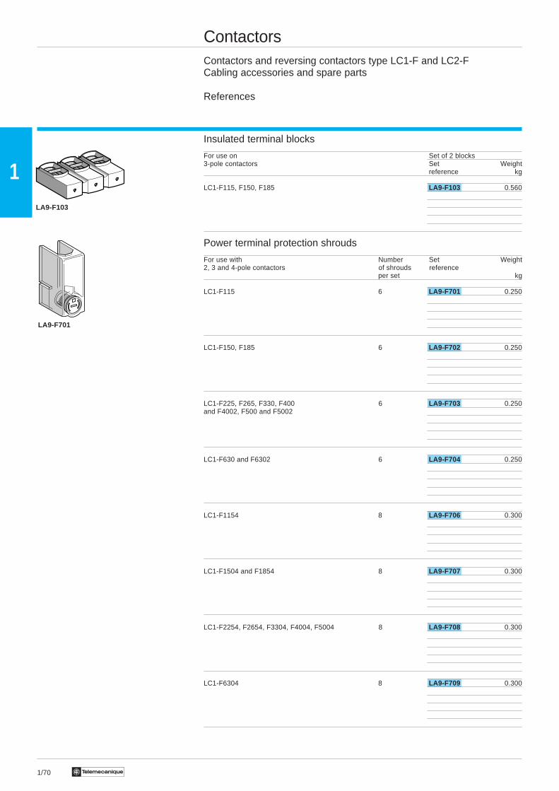
Insulated terminal blocks
For use on Set of 2 blocks3-pole contactors Set Weight
reference kg
LC1-F115, F150, F185 LA9-F103 0.560
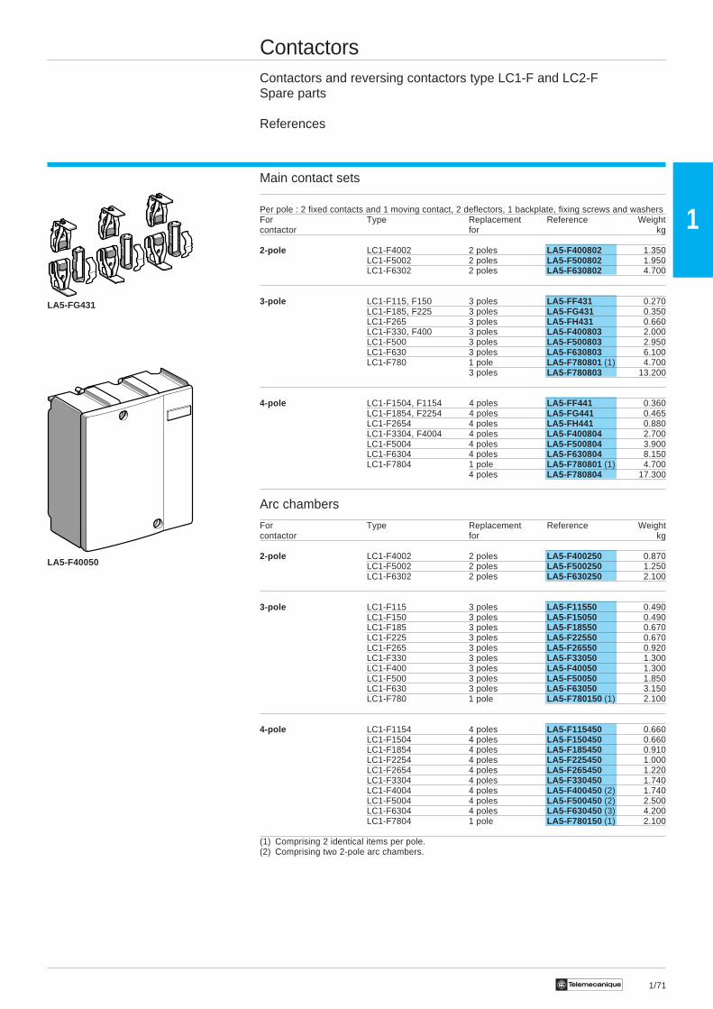
Power terminal protection shrouds
For use with Number Set Weight2, 3 and 4-pole contactors of shrouds reference
per set kg
LC1-F115 6 LA9-F701 0.250
LC1-F150, F185 6 LA9-F702 0.250
LC1-F225, F265, F330, F400 6 LA9-F703 0.250and F4002, F500 and F5002
LC1-F630 and F6302 6 LA9-F704 0.250
LC1-F1154 8 LA9-F706 0.300
LC1-F1504 and F1854 8 LA9-F707 0.300
LC1-F2254, F2654, F3304, F4004, F5004 8 LA9-F708 0.300
LC1-F6304 8 LA9-F709 0.300
LA9-F103
LA9-F701
1/71Te
1
ContactorsContactors and reversing contactors type LC1-F and LC2-FSpare parts
References
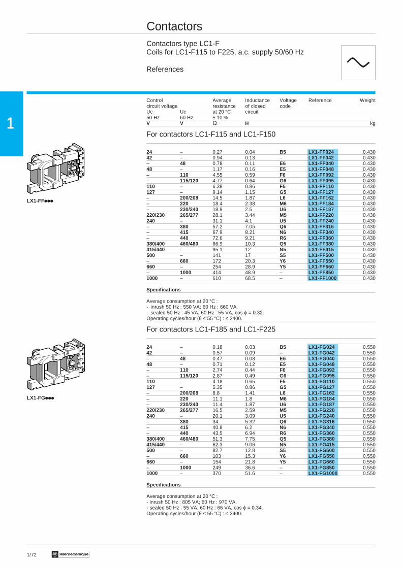
Main contact sets
Per pole : 2 fixed contacts and 1 moving contact, 2 deflectors, 1 backplate, fixing screws and washersFor Type Replacement Reference Weightcontactor for kg
2-pole LC1-F4002 2 poles LA5-F400802 1.350LC1-F5002 2 poles LA5-F500802 1.950LC1-F6302 2 poles LA5-F630802 4.700
3-pole LC1-F115, F150 3 poles LA5-FF431 0.270LC1-F185, F225 3 poles LA5-FG431 0.350LC1-F265 3 poles LA5-FH431 0.660LC1-F330, F400 3 poles LA5-F400803 2.000LC1-F500 3 poles LA5-F500803 2.950LC1-F630 3 poles LA5-F630803 6.100LC1-F780 1 pole LA5-F780801 (1) 4.700
3 poles LA5-F780803 13.200
4-pole LC1-F1504, F1154 4 poles LA5-FF441 0.360LC1-F1854, F2254 4 poles LA5-FG441 0.465LC1-F2654 4 poles LA5-FH441 0.880LC1-F3304, F4004 4 poles LA5-F400804 2.700LC1-F5004 4 poles LA5-F500804 3.900LC1-F6304 4 poles LA5-F630804 8.150LC1-F7804 1 pole LA5-F780801 (1) 4.700
4 poles LA5-F780804 17.300
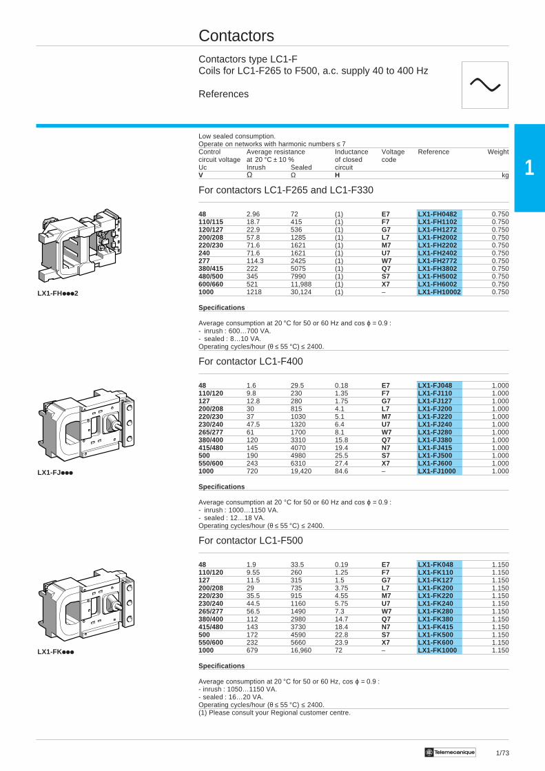
Arc chambers
For Type Replacement Reference Weightcontactor for kg
2-pole LC1-F4002 2 poles LA5-F400250 0.870LC1-F5002 2 poles LA5-F500250 1.250LC1-F6302 2 poles LA5-F630250 2.100
3-pole LC1-F115 3 poles LA5-F11550 0.490LC1-F150 3 poles LA5-F15050 0.490LC1-F185 3 poles LA5-F18550 0.670LC1-F225 3 poles LA5-F22550 0.670LC1-F265 3 poles LA5-F26550 0.920LC1-F330 3 poles LA5-F33050 1.300LC1-F400 3 poles LA5-F40050 1.300LC1-F500 3 poles LA5-F50050 1.850LC1-F630 3 poles LA5-F63050 3.150LC1-F780 1 pole LA5-F780150 (1) 2.100
4-pole LC1-F1154 4 poles LA5-F115450 0.660LC1-F1504 4 poles LA5-F150450 0.660LC1-F1854 4 poles LA5-F185450 0.910LC1-F2254 4 poles LA5-F225450 1.000LC1-F2654 4 poles LA5-F265450 1.220LC1-F3304 4 poles LA5-F330450 1.740LC1-F4004 4 poles LA5-F400450 (2) 1.740LC1-F5004 4 poles LA5-F500450 (2) 2.500LC1-F6304 4 poles LA5-F630450 (3) 4.200LC1-F7804 1 pole LA5-F780150 (1) 2.100
(1) Comprising 2 identical items per pole.(2) Comprising two 2-pole arc chambers.
LA5-FG431
LA5-F40050
1/72 Te
1
ContactorsContactors type LC1-FCoils for LC1-F115 to F225, a.c. supply 50/60 Hz
References
Control Average Inductance Voltage Reference Weightcircuit voltage resistance of closed codeUc Uc at 20 °C circuit50 Hz 60 Hz ± 10 %V V Ω H kg
For contactors LC1-F115 and LC1-F150
24 – 0.27 0.04 B5 LX1-FF024 0.43042 – 0.94 0.13 – LX1-FF042 0.430– 48 0.78 0.11 E6 LX1-FF040 0.43048 – 1.17 0.16 E5 LX1-FF048 0.430– 110 4.55 0.59 F6 LX1-FF092 0.430– 115/120 4.77 0.64 G6 LX1-FF095 0.430110 – 6.38 0.86 F5 LX1-FF110 0.430127 – 9.14 1.15 G5 LX1-FF127 0.430– 200/208 14.5 1.87 L6 LX1-FF162 0.430– 220 18.4 2.38 M6 LX1-FF184 0.430– 230/240 18.9 2.5 U6 LX1-FF187 0.430220/230 265/277 28.1 3.44 M5 LX1-FF220 0.430240 – 31.1 4.1 U5 LX1-FF240 0.430– 380 57.2 7.05 Q6 LX1-FF316 0.430– 415 67.9 8.21 N6 LX1-FF340 0.430– 440 72.6 9.21 R6 LX1-FF360 0.430380/400 460/480 86.9 10.3 Q5 LX1-FF380 0.430415/440 – 95.1 12 N5 LX1-FF415 0.430500 – 141 17 S5 LX1-FF500 0.430– 660 172 20.3 Y6 LX1-FF550 0.430660 – 254 28.9 Y5 LX1-FF660 0.430– 1000 414 48.9 – LX1-FF850 0.4301000 – 610 68.5 – LX1-FF1000 0.430
Specifications
Average consumption at 20 °C :- inrush 50 Hz : 550 VA; 60 Hz : 660 VA.- sealed 50 Hz : 45 VA; 60 Hz : 55 VA, cos ϕ = 0.32.Operating cycles/hour (θ ≤ 55 °C) : ≤ 2400.
For contactors LC1-F185 and LC1-F225
24 – 0.18 0.03 B5 LX1-FG024 0.55042 – 0.57 0.09 – LX1-FG042 0.550– 48 0.47 0.08 E6 LX1-FG040 0.55048 – 0.71 0.12 E5 LX1-FG048 0.550– 110 2.74 0.44 F6 LX1-FG092 0.550– 115/120 2.87 0.49 G6 LX1-FG095 0.550110 – 4.18 0.65 F5 LX1-FG110 0.550127 – 5.35 0.86 G5 LX1-FG127 0.550– 200/208 8.8 1.41 L6 LX1-FG162 0.550– 220 11.1 1.8 M6 LX1-FG184 0.550– 230/240 11.4 1.87 U6 LX1-FG187 0.550220/230 265/277 16.5 2.59 M5 LX1-FG220 0.550240 – 20.1 3.09 U5 LX1-FG240 0.550– 380 34 5.32 Q6 LX1-FG316 0.550– 415 40.8 6.2 N6 LX1-FG340 0.550– 440 43.5 6.94 R6 LX1-FG360 0.550380/400 460/480 51.3 7.75 Q5 LX1-FG380 0.550415/440 – 62.3 9.06 N5 LX1-FG415 0.550500 – 82.7 12.8 S5 LX1-FG500 0.550– 660 103 15.3 Y6 LX1-FG550 0.550660 – 154 21.8 Y5 LX1-FG660 0.550– 1000 249 36.6 – LX1-FG850 0.5501000 – 370 51.6 – LX1-FG1000 0.550
Specifications
Average consumption at 20 °C :- inrush 50 Hz : 805 VA; 60 Hz : 970 VA.- sealed 50 Hz : 55 VA; 60 Hz : 66 VA, cos ϕ = 0.34.Operating cycles/hour (θ ≤ 55 °C) : ≤ 2400.
LX1-FGiii
LX1-FFiii
c
1/73Te
1
ContactorsContactors type LC1-FCoils for LC1-F265 to F500, a.c. supply 40 to 400 Hz
References
Low sealed consumption.Operate on networks with harmonic numbers ≤ 7Control Average resistance Inductance Voltage Reference Weightcircuit voltage at 20 °C ± 10 % of closed codeUc Inrush Sealed circuitV Ω Ω H kg
For contactors LC1-F265 and LC1-F330
48 2.96 72 (1) E7 LX1-FH0482 0.750110/115 18.7 415 (1) F7 LX1-FH1102 0.750120/127 22.9 536 (1) G7 LX1-FH1272 0.750200/208 57.8 1285 (1) L7 LX1-FH2002 0.750220/230 71.6 1621 (1) M7 LX1-FH2202 0.750240 71.6 1621 (1) U7 LX1-FH2402 0.750277 114.3 2425 (1) W7 LX1-FH2772 0.750380/415 222 5075 (1) Q7 LX1-FH3802 0.750480/500 345 7990 (1) S7 LX1-FH5002 0.750600/660 521 11,988 (1) X7 LX1-FH6002 0.7501000 1218 30,124 (1) – LX1-FH10002 0.750
Specifications
Average consumption at 20 °C for 50 or 60 Hz and cos ϕ = 0.9 :- inrush : 600…700 VA.- sealed : 8…10 VA.Operating cycles/hour (θ ≤ 55 °C) ≤ 2400.
For contactor LC1-F400
48 1.6 29.5 0.18 E7 LX1-FJ048 1.000110/120 9.8 230 1.35 F7 LX1-FJ110 1.000127 12.8 280 1.75 G7 LX1-FJ127 1.000200/208 30 815 4.1 L7 LX1-FJ200 1.000220/230 37 1030 5.1 M7 LX1-FJ220 1.000230/240 47.5 1320 6.4 U7 LX1-FJ240 1.000265/277 61 1700 8.1 W7 LX1-FJ280 1.000380/400 120 3310 15.8 Q7 LX1-FJ380 1.000415/480 145 4070 19.4 N7 LX1-FJ415 1.000500 190 4980 25.5 S7 LX1-FJ500 1.000550/600 243 6310 27.4 X7 LX1-FJ600 1.0001000 720 19,420 84.6 – LX1-FJ1000 1.000
Specifications
Average consumption at 20 °C for 50 or 60 Hz and cos ϕ = 0.9 :- inrush : 1000…1150 VA.- sealed : 12…18 VA.Operating cycles/hour (θ ≤ 55 °C) ≤ 2400.
For contactor LC1-F500
48 1.9 33.5 0.19 E7 LX1-FK048 1.150110/120 9.55 260 1.25 F7 LX1-FK110 1.150127 11.5 315 1.5 G7 LX1-FK127 1.150200/208 29 735 3.75 L7 LX1-FK200 1.150220/230 35.5 915 4.55 M7 LX1-FK220 1.150230/240 44.5 1160 5.75 U7 LX1-FK240 1.150265/277 56.5 1490 7.3 W7 LX1-FK280 1.150380/400 112 2980 14.7 Q7 LX1-FK380 1.150415/480 143 3730 18.4 N7 LX1-FK415 1.150500 172 4590 22.8 S7 LX1-FK500 1.150550/600 232 5660 23.9 X7 LX1-FK600 1.1501000 679 16,960 72 – LX1-FK1000 1.150
Specifications
Average consumption at 20 °C for 50 or 60 Hz, cos ϕ = 0.9 :- inrush : 1050…1150 VA.- sealed : 16…20 VA.Operating cycles/hour (θ ≤ 55 °C) ≤ 2400.(1) Please consult your Regional customer centre.
LX1-FHiii2
LX1-FJiii
LX1-FKiii
c
1/74 Te
1
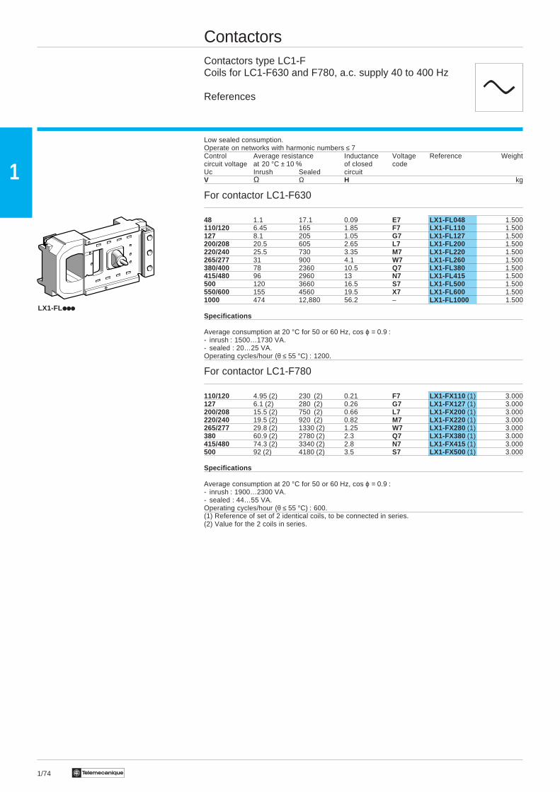
ContactorsContactors type LC1-FCoils for LC1-F630 and F780, a.c. supply 40 to 400 Hz
References
Low sealed consumption.Operate on networks with harmonic numbers ≤ 7Control Average resistance Inductance Voltage Reference Weightcircuit voltage at 20 °C ± 10 % of closed codeUc Inrush Sealed circuitV Ω Ω H kg
For contactor LC1-F630
48 1.1 17.1 0.09 E7 LX1-FL048 1.500110/120 6.45 165 1.85 F7 LX1-FL110 1.500127 8.1 205 1.05 G7 LX1-FL127 1.500200/208 20.5 605 2.65 L7 LX1-FL200 1.500220/240 25.5 730 3.35 M7 LX1-FL220 1.500265/277 31 900 4.1 W7 LX1-FL260 1.500380/400 78 2360 10.5 Q7 LX1-FL380 1.500415/480 96 2960 13 N7 LX1-FL415 1.500500 120 3660 16.5 S7 LX1-FL500 1.500550/600 155 4560 19.5 X7 LX1-FL600 1.5001000 474 12,880 56.2 – LX1-FL1000 1.500
Specifications
Average consumption at 20 °C for 50 or 60 Hz, cos ϕ = 0.9 :- inrush : 1500…1730 VA.- sealed : 20…25 VA.Operating cycles/hour (θ ≤ 55 °C) : 1200.
For contactor LC1-F780
110/120 4.95 (2) 230 (2) 0.21 F7 LX1-FX110 (1) 3.000127 6.1 (2) 280 (2) 0.26 G7 LX1-FX127 (1) 3.000200/208 15.5 (2) 750 (2) 0.66 L7 LX1-FX200 (1) 3.000220/240 19.5 (2) 920 (2) 0.82 M7 LX1-FX220 (1) 3.000265/277 29.8 (2) 1330 (2) 1.25 W7 LX1-FX280 (1) 3.000380 60.9 (2) 2780 (2) 2.3 Q7 LX1-FX380 (1) 3.000415/480 74.3 (2) 3340 (2) 2.8 N7 LX1-FX415 (1) 3.000500 92 (2) 4180 (2) 3.5 S7 LX1-FX500 (1) 3.000
Specifications
Average consumption at 20 °C for 50 or 60 Hz, cos ϕ = 0.9 :- inrush : 1900…2300 VA.- sealed : 44…55 VA.Operating cycles/hour (θ ≤ 55 °C) : 600.(1) Reference of set of 2 identical coils, to be connected in series.(2) Value for the 2 coils in series.
LX1-FL
c
1/75Te
1
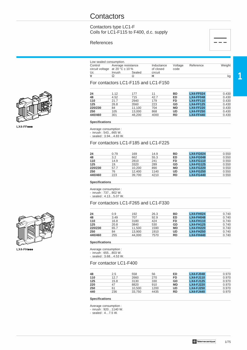
ContactorsContactors type LC1-FCoils for LC1-F115 to F400, d.c. supply
References
Low sealed consumption.Control Average resistance Inductance Voltage Reference Weightcircuit voltage at 20 °C ± 10 % of closed codeUc Inrush Sealed circuitV Ω Ω H kg
For contactors LC1-F115 and LC1-F150
24 1.12 177 11 BD LX4-FF024 0.43048 4.52 715 42.7 ED LX4-FF048 0.430110 21.7 2940 179 FD LX4-FF110 0.430125 26.8 3560 223 GD LX4-FF125 0.430220/230 84 11,100 704 MD LX4-FF220 0.430250 105 13,000 868 UD LX4-FF250 0.430440/460 301 48,200 4000 RD LX4-FF440 0.430
Specifications
Average consumption :- inrush : 543…665 W.- sealed : 3.94…4.83 W.
For contactors LC1-F185 and LC1-F225
24 0.79 169 14.9 BD LX4-FG024 0.55048 3.2 662 55.3 ED LX4-FG048 0.550110 14.9 2810 241 FD LX4-FG110 0.550125 19. 3320 289 GD LX4-FG125 0.550220/230 57.7 10,200 890 MD LX4-FG220 0.550250 76 12,400 1140 UD LX4-FG250 0.550440/460 223 39,700 4210 RD LX4-FG440 0.550
Specifications
Average consumption :- inrush : 737…902 W.- sealed : 4.13…5.07 W.
For contactors LC1-F265 and LC1-F330
24 0.9 192 26.3 BD LX4-FH024 0.74048 3.49 707 92.9 ED LX4-FH048 0.740110 16.8 3180 424 FD LX4-FH110 0.740125 20.8 3840 530 GD LX4-FH125 0.740220/230 65.7 11,500 1590 MD LX4-FH220 0.740250 84 13,900 1910 UD LX4-FH250 0.740440/460 255 44,000 7570 RD LX4-FH440 0.740
Specifications
Average consumption :- inrush : 655…803 W.- sealed : 3.68…4.53 W.
For contactor LC1-F400
48 2.5 558 56 ED LX4-FJ048 0.970110 12.7 2660 270 FD LX4-FJ110 0.970125 15.8 3130 330 GD LX4-FJ125 0.970220 47 8820 910 MD LX4-FJ220 0.970250 61 10,500 1200 UD LX4-FJ250 0.970440 236 33,750 4435 RD LX4-FJ440 0.970
Specifications
Average consumption :- inrush : 920…1140 W.- sealed : 4…7.5 W.
LX4-FFiii
LX4-FHiii
a
1/76 Te
1
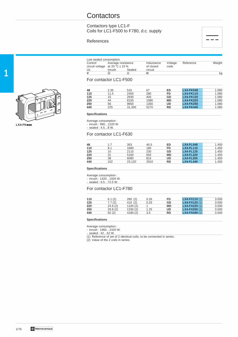
ContactorsContactors type LC1-FCoils for LC1-F500 to F780, d.c. supply
References
Low sealed consumption.Control Average resistance Inductance Voltage Reference Weightcircuit voltage at 20 °C ± 10 % of closed codeUc Inrush Sealed circuitV Ω Ω H kg
For contactor LC1-F500
48 2.35 515 67 ED LX4-FK048 1.080110 11.5 2450 280 FD LX4-FK110 1.080125 15 2930 400 GD LX4-FK125 1.080220 44 8150 1080 MD LX4-FK220 1.080250 56 9650 1350 UD LX4-FK250 1.080440 225 31,300 5270 RD LX4-FK440 1.080
Specifications
Average consumption :- inrush : 990…1220 W.- sealed : 4.5…8 W.
For contactor LC1-F630
48 1.7 353 40.5 ED LX4-FL048 1.450110 8.1 1680 180 FD LX4-FL110 1.450125 10 2110 230 GD LX4-FL125 1.450220 31 5160 650 MD LX4-FL220 1.450250 38 6080 815 UD LX4-FL250 1.450440 152 23,120 2910 RD LX4-FL440 1.450
Specifications
Average consumption :- inrush : 1420…1920 W.- sealed : 6.5…72.5 W.
For contactor LC1-F780
110 6.1 (2) 280 (2) 0.26 FD LX4-FX110 (1) 3.000125 7.7 (2) 410 (2) 0.33 GD LX4-FX125 (1) 3.000220 24.6 (2) 1100 (2) 1 MD LX4-FX220 (1) 3.000250 29.8 (2) 1330 (2) 1.25 UD LX4-FX250 (1) 3.000440 92 (2) 4180 (2) 3.5 RD LX4-FX440 (1) 3.000
Specifications
Average consumption :- inrush : 1960…2420 W.- sealed : 42…52 W.(1) Reference of set of 2 identical coils, to be connected in series.(2) Value of the 2 coils in series.
LX4-FKiii
a
1/77Te
1
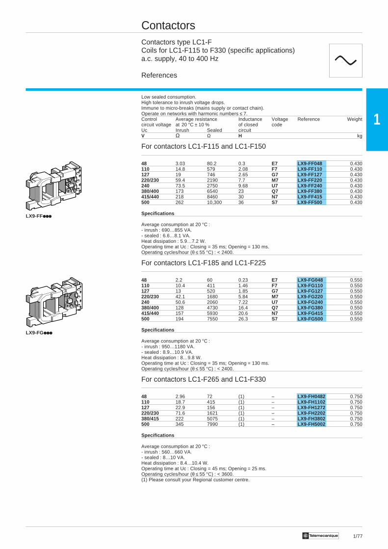
ContactorsContactors type LC1-FCoils for LC1-F115 to F330 (specific applications)a.c. supply, 40 to 400 Hz
References
Low sealed consumption.High tolerance to inrush voltage drops.Immune to micro-breaks (mains supply or contact chain).Operate on networks with harmonic numbers ≤ 7.Control Average resistance Inductance Voltage Reference Weightcircuit voltage at 20 °C ± 10 % of closed codeUc Inrush Sealed circuitV Ω Ω H kg
For contactors LC1-F115 and LC1-F150
48 3.03 80.2 0.3 E7 LX9-FF048 0.430110 14.8 579 2.08 F7 LX9-FF110 0.430127 19 746 2.65 G7 LX9-FF127 0.430220/230 59.4 2190 7.7 M7 LX9-FF220 0.430240 73.5 2750 9.68 U7 LX9-FF240 0.430380/400 173 6540 23 Q7 LX9-FF380 0.430415/440 218 8460 30 N7 LX9-FF415 0.430500 262 10,300 36 S7 LX9-FF500 0.430
Specifications
Average consumption at 20 °C :- inrush : 690…855 VA.- sealed : 6.6…8.1 VA.Heat dissipation : 5.9…7.2 W.Operating time at Uc : Closing = 35 ms; Opening = 130 ms.Operating cycles/hour (θ ≤ 55 °C) : < 2400.
For contactors LC1-F185 and LC1-F225
48 2.2 60 0.23 E7 LX9-FG048 0.550110 10.4 411 1.46 F7 LX9-FG110 0.550127 13 520 1.85 G7 LX9-FG127 0.550220/230 42.1 1680 5.84 M7 LX9-FG220 0.550240 50.6 2060 7.22 U7 LX9-FG240 0.550380/400 128 4730 16.4 Q7 LX9-FG380 0.550415/440 157 5930 20.6 N7 LX9-FG415 0.550500 194 7550 26.3 S7 LX9-FG500 0.550
Specifications
Average consumption at 20 °C :- inrush : 950…1180 VA.- sealed : 8.9…10.9 VA.Heat dissipation : 8…9.8 W.Operating time at Uc : Closing = 35 ms; Opening = 130 ms.Operating cycles/hour (θ ≤ 55 °C) : < 2400.
For contactors LC1-F265 and LC1-F330
48 2.96 72 (1) – LX9-FH0482 0.750110 18.7 415 (1) – LX9-FH1102 0.750127 22.9 156 (1) – LX9-FH1272 0.750220/230 71.6 1621 (1) – LX9-FH2202 0.750380/415 222 5075 (1) – LX9-FH3802 0.750500 345 7990 (1) – LX9-FH5002 0.750
Specifications
Average consumption at 20 °C :- inrush : 560…660 VA.- sealed : 8…10 VA.Heat dissipation : 8.4…10.4 W.Operating time at Uc : Closing = 45 ms; Opening = 25 ms.Operating cycles/hour (θ ≤ 55 °C) : < 3600.(1) Please consult your Regional customer centre.
LX9-FF
LX9-FG
c
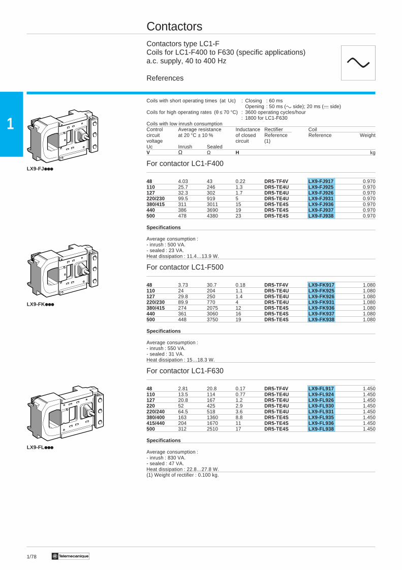
1/78 Te
1
ContactorsContactors type LC1-FCoils for LC1-F400 to F630 (specific applications)a.c. supply, 40 to 400 Hz
References
Coils with short operating times (at Uc) : Closing : 60 msOpening : 50 ms (c side); 20 ms (a side)
Coils for high operating rates (θ ≤ 70 °C) : 3600 operating cycles/hour: 1800 for LC1-F630
Coils with low inrush consumptionControl Average resistance Inductance Rectifier Coilcircuit at 20 °C ± 10 % of closed Reference Reference Weightvoltage circuit (1)Uc Inrush SealedV Ω Ω H kg
For contactor LC1-F400
48 4.03 43 0.22 DR5-TF4V LX9-FJ917 0.970110 25.7 246 1.3 DR5-TE4U LX9-FJ925 0.970127 32.3 302 1.7 DR5-TE4U LX9-FJ926 0.970220/230 99.5 919 5 DR5-TE4U LX9-FJ931 0.970380/415 311 3011 15 DR5-TE4S LX9-FJ936 0.970440 386 3690 19 DR5-TE4S LX9-FJ937 0.970500 478 4380 23 DR5-TE4S LX9-FJ938 0.970
Specifications
Average consumption :- inrush : 500 VA.- sealed : 23 VA.Heat dissipation : 11.4…13.9 W.
For contactor LC1-F500
48 3.73 30.7 0.18 DR5-TF4V LX9-FK917 1.080110 24 204 1.1 DR5-TE4U LX9-FK925 1.080127 29.8 250 1.4 DR5-TE4U LX9-FK926 1.080220/230 89.9 770 4 DR5-TE4U LX9-FK931 1.080380/415 274 2075 12 DR5-TE4S LX9-FK936 1.080440 361 3060 16 DR5-TE4S LX9-FK937 1.080500 448 3750 19 DR5-TE4S LX9-FK938 1.080
Specifications
Average consumption :- inrush : 550 VA.- sealed : 31 VA.Heat dissipation : 15…18.3 W.
For contactor LC1-F630
48 2.81 20.8 0.17 DR5-TF4V LX9-FL917 1.450110 13.5 114 0.77 DR5-TE4U LX9-FL924 1.450127 20.8 167 1.2 DR5-TE4U LX9-FL926 1.450220 52 425 2.9 DR5-TE4U LX9-FL930 1.450220/240 64.5 518 3.6 DR5-TE4U LX9-FL931 1.450380/400 163 1360 8.8 DR5-TE4S LX9-FL935 1.450415/440 204 1670 11 DR5-TE4S LX9-FL936 1.450500 312 2510 17 DR5-TE4S LX9-FL938 1.450
Specifications
Average consumption :- inrush : 830 VA.- sealed : 47 VA.Heat dissipation : 22.8…27.8 W.(1) Weight of rectifier : 0.100 kg.
LX9-FL
LX9-FJ
LX9-FK
c
1/79Te
1
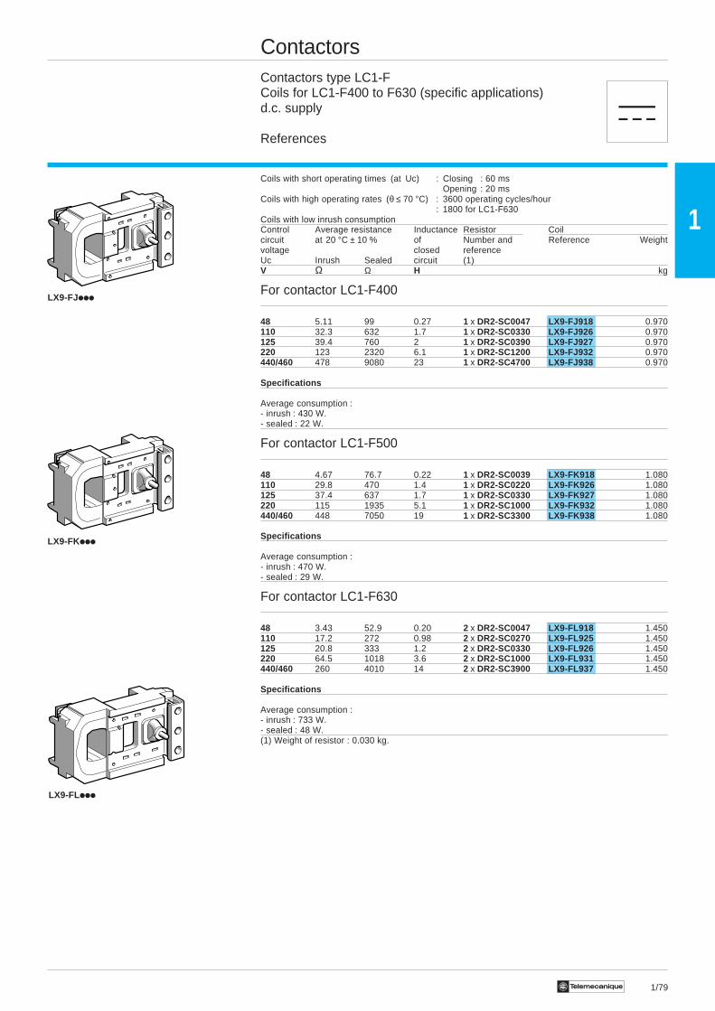
ContactorsContactors type LC1-FCoils for LC1-F400 to F630 (specific applications)d.c. supply
References
Coils with short operating times (at Uc) : Closing : 60 msOpening : 20 ms
Coils with high operating rates (θ ≤ 70 °C) : 3600 operating cycles/hour: 1800 for LC1-F630
Coils with low inrush consumptionControl Average resistance Inductance Resistor Coilcircuit at 20 °C ± 10 % of Number and Reference Weightvoltage closed referenceUc Inrush Sealed circuit (1)V Ω Ω H kg
For contactor LC1-F400
48 5.11 99 0.27 1 x DR2-SC0047 LX9-FJ918 0.970110 32.3 632 1.7 1 x DR2-SC0330 LX9-FJ926 0.970125 39.4 760 2 1 x DR2-SC0390 LX9-FJ927 0.970220 123 2320 6.1 1 x DR2-SC1200 LX9-FJ932 0.970440/460 478 9080 23 1 x DR2-SC4700 LX9-FJ938 0.970
Specifications
Average consumption :- inrush : 430 W.- sealed : 22 W.
For contactor LC1-F500
48 4.67 76.7 0.22 1 x DR2-SC0039 LX9-FK918 1.080110 29.8 470 1.4 1 x DR2-SC0220 LX9-FK926 1.080125 37.4 637 1.7 1 x DR2-SC0330 LX9-FK927 1.080220 115 1935 5.1 1 x DR2-SC1000 LX9-FK932 1.080440/460 448 7050 19 1 x DR2-SC3300 LX9-FK938 1.080
Specifications
Average consumption :- inrush : 470 W.- sealed : 29 W.
For contactor LC1-F630
48 3.43 52.9 0.20 2 x DR2-SC0047 LX9-FL918 1.450110 17.2 272 0.98 2 x DR2-SC0270 LX9-FL925 1.450125 20.8 333 1.2 2 x DR2-SC0330 LX9-FL926 1.450220 64.5 1018 3.6 2 x DR2-SC1000 LX9-FL931 1.450440/460 260 4010 14 2 x DR2-SC3900 LX9-FL937 1.450
Specifications
Average consumption :- inrush : 733 W.- sealed : 48 W.(1) Weight of resistor : 0.030 kg.
LX9-FLiii
LX9-FKiii
LX9-FJiii
a
1/80 Te
1
LR9-F73ii
120
60
5050
71
5,5
56,8
123,5
3
46,83
44,8
(1)
76
25
4848
101
115
Ø11
4xØ5,5
76
4040
96
(2)
5050
60 71
5,5
4xØ5,5
115
20
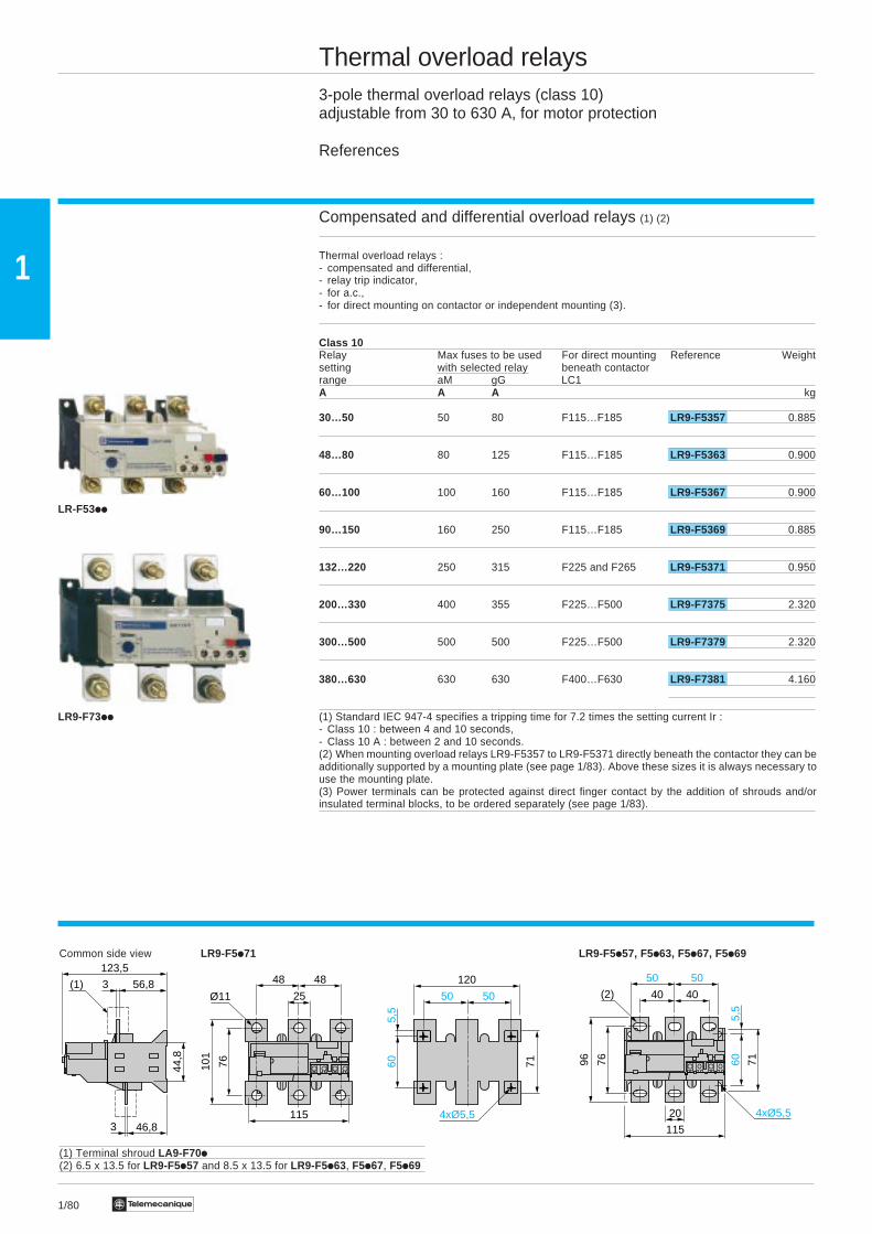
Thermal overload relays3-pole thermal overload relays (class 10)adjustable from 30 to 630 A, for motor protection
References
Compensated and differential overload relays (1) (2)
Thermal overload relays :- compensated and differential,- relay trip indicator,- for a.c.,- for direct mounting on contactor or independent mounting (3).
Class 10Relay Max fuses to be used For direct mounting Reference Weightsetting with selected relay beneath contactorrange aM gG LC1A A A kg
30…50 50 80 F115…F185 LR9-F5357 0.885
48…80 80 125 F115…F185 LR9-F5363 0.900
60…100 100 160 F115…F185 LR9-F5367 0.900
90…150 160 250 F115…F185 LR9-F5369 0.885
132…220 250 315 F225 and F265 LR9-F5371 0.950
200…330 400 355 F225…F500 LR9-F7375 2.320
300…500 500 500 F225…F500 LR9-F7379 2.320
380…630 630 630 F400…F630 LR9-F7381 4.160
(1) Standard IEC 947-4 specifies a tripping time for 7.2 times the setting current Ir :- Class 10 : between 4 and 10 seconds,- Class 10 A : between 2 and 10 seconds.(2) When mounting overload relays LR9-F5357 to LR9-F5371 directly beneath the contactor they can beadditionally supported by a mounting plate (see page 1/83). Above these sizes it is always necessary touse the mounting plate.(3) Power terminals can be protected against direct finger contact by the addition of shrouds and/orinsulated terminal blocks, to be ordered separately (see page 1/83).
Common side view LR9-F5i71 LR9-F5i57, F5i63, F5i67, F5i69
(1) Terminal shroud LA9-F70i(2) 6.5 x 13.5 for LR9-F5i57 and 8.5 x 13.5 for LR9-F5i63, F5i67, F5i69
LR-F53ii

1/81Te
1
108,
814
30
P2 P1
151,3
Ø11
51,5 51,5
66 66
4xØ5,5
7022
,1
6
82 136,
8
25
42,2
127,6
6
44,8
(1)
188,
820
200
8080
193
228,
8
76,5 76,5
62,1
Ø13
40
40
Thermal overload relays3-pole thermal overload relays (class 20)adjustable from 30 to 630 A, for motor protection
References
Compensated and differential overload relays (1) (2)
Thermal overload relays :- compensated and differential,- relay trip indicator,- for a.c.,- for direct mounting on contactor or independent mounting (3).
Class 20Relay Max fuses to be used For direct mounting Reference Weightsetting with selected relay beneath contactorrange aM gG LC1A A A kg
30…50 80 125 F115…F185 LR9-F5557 0.885
48…80 100 160 F115…F185 LR9-F5563 0.900
60…100 125 200 F115…F185 LR9-F5567 0.900
90…150 200 250 F115…F185 LR9-F5569 0.885
132…220 315 355 F225 and F265 LR9-F5571 0.950
200…330 400 500 F225…F500 LR9-F7575 2.320
300…500 630 710 F225…F500 LR9-F7579 2.320
380…630 800 800 F400…F630 LR9-F7581 4.160and F800
(1) Standard IEC 947-4 specifies a tripping time for 7.2 times the setting current Ir :- Class 20 : between 6 and 20 seconds.(2) When mounting overload relays LR9-F5557 to LR9-F5571 directly beneath the contactor they can beadditionally supported by a mounting plate (see page 1/83). Above these sizes it is always necessary touse the mounting plate.(3) Power terminals can be protected against direct finger contact by the addition of shrouds and/orinsulated terminal blocks, to be ordered separately (see page 1/83).
Common side view LR9-F7i75, F7i79, F7i81 LR9-F7i81 (for mounting beneath LC1-F630)
P1 P2LR9-F7i75 48 48LR9-F7i79, F7i81 55 55(1) Terminal shroud LA9-F70i
LR9-F5557
1/82 Te
1
Thermal overload relays3-pole thermal overload relays, adjustable from 30 to 630 AAccessories (to be ordered separately)
References
Control accessories
Description Sold in Unit Weightlots of reference kg
Remote electrical reset 1 LA7-D03i (2) 0.090device (1)
Remote reset function control 1 LA7-D305 0.075by flexible cable (length = 0.5 m)
Remote Stop and/or Adaptor for door mounted 1 LA7-D1020 0.005Reset function control operatorFor fitting, order thefollowing 3 products :
Rod (snap-off end to obtain 10 ZA2-BZ13 0.100required length, between 17and 120 mm)
Operating head for spring 1 ZA2-Biiii (3) 0.012return pushbutton
(1) Reference to be completed by adding coil voltage code.Standard control circuit voltages (for other voltages, please consult your Regional customer centre).Volts 12 24 48 96 110 220/230 380/400 415/440c 50/60 Hz – B E – F M Q NConsumption, inrush and sealed : < 100 VAa J B E DD F M – –Consumption, inrush and sealed : < 100 W
(2) The time for which the coil of remote electrical reset device LA7-D03 can remain energised dependson its rest time : 1 s pulse duration with 9 s rest time ; 5 s pulse duration with 30 s rest time ; 10 s pulseduration with 90 s rest time : maximum pulse duration of 20 s with rest time of 300 s. Minimum impulsetime : 200 ms.(3) Reference to be completed, please refer to chapter 5.
1/83Te
1
LA7-F70i
LA7-F90i
LA9-F70i
LA9-F103
Thermal overload relays3-pole thermal overload relays, adjustable from 30 to 630 AAccessories (to be ordered separately)
References
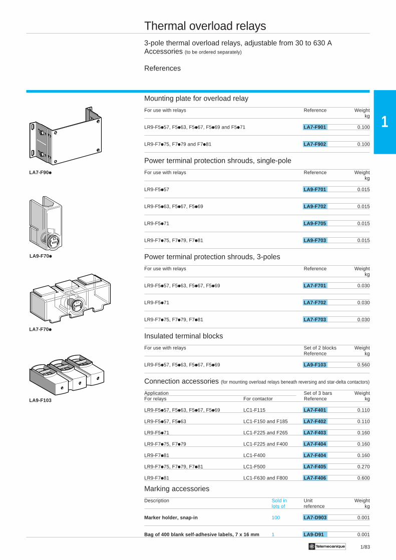
Mounting plate for overload relay
For use with relays Reference Weightkg
LR9-F5i57, F5i63, F5i67, F5i69 and F5i71 LA7-F901 0.100
LR9-F7i75, F7i79 and F7i81 LA7-F902 0.100
Power terminal protection shrouds, single-pole
For use with relays Reference Weightkg
LR9-F5i57 LA9-F701 0.015
LR9-F5i63, F5i67, F5i69 LA9-F702 0.015
LR9-F5i71 LA9-F705 0.015
LR9-F7i75, F7i79, F7i81 LA9-F703 0.015
Power terminal protection shrouds, 3-poles
For use with relays Reference Weightkg
LR9-F5i57, F5i63, F5i67, F5i69 LA7-F701 0.030
LR9-F5i71 LA7-F702 0.030
LR9-F7i75, F7i79, F7i81 LA7-F703 0.030
Insulated terminal blocks
For use with relays Set of 2 blocks WeightReference kg
LR9-F5i57, F5i63, F5i67, F5i69 LA9-F103 0.560
Connection accessories (for mounting overload relays beneath reversing and star-delta contactors)
Application Set of 3 bars WeightFor relays For contactor Reference kg
LR9-F5i57, F5i63, F5i67, F5i69 LC1-F115 LA7-F401 0.110
LR9-F5i57, F5i63 LC1-F150 and F185 LA7-F402 0.110
LR9-F5i71 LC1-F225 and F265 LA7-F403 0.160
LR9-F7i75, F7i79 LC1-F225 and F400 LA7-F404 0.160
LR9-F7i81 LC1-F400 LA7-F404 0.160
LR9-F7i75, F7i79, F7i81 LC1-F500 LA7-F405 0.270
LR9-F7i81 LC1-F630 and F800 LA7-F406 0.600
Marking accessories
Description Sold in Unit Weightlots of reference kg
Marker holder, snap-in 100 LA7-D903 0.001
Bag of 400 blank self-adhesive labels, 7 x 16 mm 1 LA9-D91 0.001