Embed Size (px)
Citation preview
CONTRACTOR REPORT
SAND80-7171 Unlimited Release UC-63a
The Design of a Photovoltaic System for a Passive Design Northeast All-Electric Residence
E. M. Mehalick, G. F. Tully, J. Johnson, J. Parker, R. Felice Philadelphia, PA 19101
Prepared by Sandia National Laboratories Albuquerque, New Mexico 87185 and Livermore, California 94550 for the Uhited States Department of Energy under Contract DE-AC04-76DP00789
Printed January 1982

Issued by Sandia National Laboratories, operated for the United States Department of Energy by Sandia Corporation. NOTICE: This report was prepared as an account of work sponsored by an agency of the United States Government. Neither the United States Govern· ment nor any agency thereof, nor any of their employees, nor any of their contractors, subcontractors, or their employees, makes any warranty, express or implied, or assumes any legal liability or responsibility for the accuracy, completeness, or usefulness of any information, apparatus, product, or process disclosed, or represents that its use would not infringe privately owned rights. Reference herein to any specific commercial product, process, or service by trade name, trademark, manufacturer, or otherwise, does not necessarily constitute or imply its endorsement, recommendation, or favoring by the United States Government, any agency thereof or any of their contractors or subcontractors. The views and opinions expressed herein do not necessarily state or reflect those of the United States Government, any agency thereof or any of their contractors or subcontractors.
Printed in the United States of America Available from National Technical Information Service U.S. Department of Commerce 5285 Port Royal Road Springfield, VA 22161
NTIS price codes Printed copy: $12.50 Microfiche copy: AO!
Distribution Category UC-63a
SAND80-7171 Unlimited Distribution Printed January 1982
THE DESIGN OF A PHOTOVOLTAIC SYSTEM FOR A PASSIVE DESIGN NORTHEAST ALL-ELECTRIC RESIDENCE
E. M. Mehalick, G. F. Tully, J. Johnson, J. Parker, R. Felice
General Electric Energy Systems and Technology Division General Electric
Advanced Energy Programs Department P. O. Box 8555
Philadelphia, Penn. 19101
ABSTRACT
A photovoltaic system has been developed and integrated into a passively designed, low energy consuming home suitable for the Northeast region of the country. The selected array size is 4.1 kW at NOCT conditions, and covers 51 sq.m. of roof area. The design addresses the residential market segment of low energy consuming houses with limited roof area availability for photovoltaic arrays. A direct mount, next generation, larger sized, PV shingle module is used to reduce installation costs over earlier generation shingle modules. A 4 kW line-commutated inverter is used in the power conversion subsystem, since it is representative of currently available equipment. This report describes the complete system and house design, including all the pertinent installation and construction drawings. Specific performance results are presented for the Boston and Madison region. The system design presented in the report, coupled with previously completed designs, provide a set of design options expected to be available to residential homeowners in the mid 1980's.
Prepared for Sandia National Laboratories under Contract No. 13-8779.
iii-iv

FOREWARD
This report presents the fourth of six detailed residential designs
developed on the Detailed Residential Photovoltaic System Preferred Designs
Study. The Advanced Energy Programs Department of the General Electric Company,
Energy Systems and Technology Division, performed the contract under Sandia
National Laboratories, Contract 13-8779. Mr. E. M. Mehalick served as the GE
Program Manager and Dr. G. Jones served as the Sandia Technical Monitor.
The choice of hardware for this design is made primarily based on
available data within the time constraints of this effort and should not be
considered an endorsement of the hardware. The set of designs consider the
implementation of various hardware components, including different flat PV
modules, selected roof mounting techniques and various power conditioning
equipment. The complete set of system designs, therefore, provide detailed
design information on several manufacturers' hardware options.
The intent of the detailed design is to provide sufficient detail for
obtaining a system installation cost estimate. A design package for this
installation can be formulated using the two appendices (Appendix A, Power
Conversion Subsystem Specification; and Appendix B, Electrical Installation
Specifications), along with a drawings package (architectural drawings AI-All
and electrical drawings E1-E9). These drawings are included as foldouts within
the report text and a full size set is delivered to Sandia.
The system design development and preparation of this report was
supported by contributions of the following individuals: Mr. G. Tully, of
Massdesign Architects and Planners, Inc., for the residential house design, and
photovoltaic array installation details; Mr. G. W. Johnson, of Johnson and
v

Stover, Inc., for the electrical system installation specification; General
Electric employees including Mr. R. Felice for overall system design and Mr. J.
Parker for system performance analysis.
vi
SECTION
1
2
3
4
5
6
7
TABLE OF CONTENTS
BACKGROUND
Application Description Design Criteria Project Team Report Format
SUMMARY
SYSTEM DESCRIPTION
Functional Description System Design Requirements Performance Characteristics Design Tradeoffs Design Performance
HOUSE DESIGN
Design Features House Plans Description of the Passive
Solar Heating System
SUBSYSTEM SPECIFICATIONS
Solar Array Power Conversion Subsystem PV Array Electrical Interface
To Conventional House System
SYSTEM DESIGN ALTERNATIVES
REFERENCES
APPENDICES
A
B
C
D
POWER CONVERSION SUBSYSTEM SPECIFICATION
ELECTRICAL SYSTEM INSTALLATION SPECIFICATION
INSTALLATION SAFETY NOTES
PERFORMANCE SIMULATION MODEL AND INPUT DATA
vii
PAGE
1-1
1-1 1-1 1-4 1-5
2-1
3-1
3-1 3-6 3-9 3-11 3-19
4-1
4-1 4-2 4-23
5-1
5-1 5-20 5-37
6-1
7-1
A-I
B-1
C-l
D-l

SECTION
E
F
TABLE OF CONTENTS
ECONOMIC MODEL AND ASSUMPTIONS
RECTANGULAR PV SHINGLE MODULE CONSTRUCTION
viii
PAGE
E-l
F-l
SECTION 1
BACKGROUND
Application Description
The photovoltaic (PV) system design described in this report is for a
residential two-story, passively heated house located in the Northeast region of
the country typified by the Boston/Madison weather environment. The house
design presents a minimum of south facing roof typical of this style. The house
is assumed newly constructed in 1986 with a living floor area of 157 sq.m. (1690
sq.ft.) and a rectangular south facing roof area of 57 sq.m. (614 sq.ft.). A
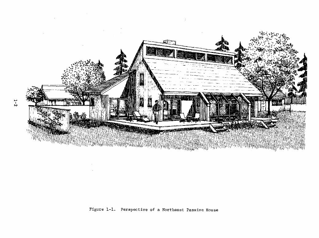
perspective of the house is shown in Figure 1-1. The design includes energy
conservation features projected for 1986 and additional passive design features
such as a greenhouse. An advanced performance 2 1/2 ton heat pump is used for
heating and cooling with an electric hot water heater. The garage is separate
from the house. The equipment area is located in the basement area.
The electrical energy derived from the PV system serves the normal
household electrical requirements including general appliances, lighting,
cooking, hot water heating and heat pump operation. When PV generated energy
exceeds the house requirements, excess energy is directed back to the utility
grid.
Design Criteria
The objective of the program is to develop designs of residential
photovoltaic systems which can be used as reference designs estimates. The
level of detail is sufficient to allow independent cost estimates for
installation of the system. Specifications for equipment are based on currently
1-1
..... I
to.)
Figure 1-1. Perspective of a Northeast Passive House

available components or similar currently available equipment if the component
is not available at present.
In general, the homeowner is considered the system user; therefore,
operation and maintenance requirements typical of conventional HVAC systems are
assumed. The system excludes instrumentation, since a mature system
installation is assumed.
To evaluate the performance of the system design, typical hourly
electrical load profiles and space conditioning demands for the house are used.
These load profiles were developed in the GE Regional Residential Study,
Reference 1, and updated in the Residential Load Center Program, Reference 2.
All the system performance analyses are completed based on these hourly loads
and using Typical Meteorological Year (TMY) weather data as developed by Sandia
National Laboratories. Life cycle cost analyses, based on system performance
results and system cost estimates, are used for system sizing and tradeoffs.
Previous designs, References 4, 15 and 16, have dealt with
applications having higher diversified electrical loads and higher space
conditioning loads. The system designs had array areas ranging from 74 sq.m. to
93 sq.m. Therefore, the design criteria used for this design requires a highly
passive house design, reducing thermal load requirements by approximatelY 50%
and improved efficiency appliances with an energy conscious family. The total
electrical load reduction is approximately 14% over the previous Northeast
residence designs. Consistent with the reduced loads is a house design having a
smaller south facing roof area. The smaller roof area requirement provides more
flexibility to the'architectural features of the house.
Furthermore, the Southwest design presented in Reference 4 used a
1-3
hexagonal shaped module with 0.196 sq.m. exposed module area. This small module
size may imply high installation costs. Therefore, the design considers a
larger shingle module (.916 sq.m. exposed module area) for comparison to the
previous design.
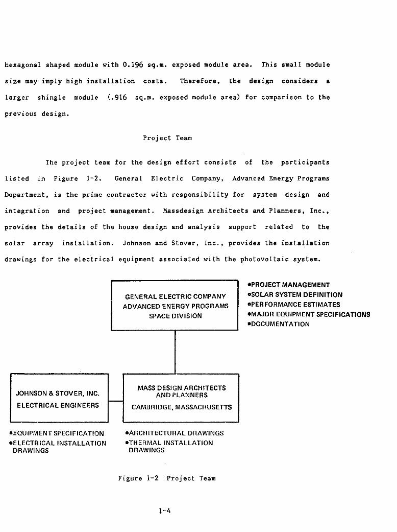
Project Team
The project team for the design effort consists of the participants
listed 1n Figure 1-2. General Electric Company, Advanced Energy Programs
Department, is the prime contractor with responsibility for system design and
integration and project management. Massdesign Architects and Planners, Inc.,
provides the details of the house design and analysis support related to the
solar array installation. Johnson and Stover, Inc., provides the installation
drawings for the electrical equipment associated with the photovoltaic system.
-PROJECT MANAGEMENT
GENERAL ELECTRIC COMPANY -SOLAR SYSTEM DEFINITION
ADVANCED ENERGY PROGRAMS .PERFORMANCE ESTIMATES
SPACE DIVISION -MAJOR EQUIPMENT SPECIFICATIONS
-DOCUMENTATION
MASS DESIGN ARCHITECTS JOHNSON & STOVER, INC. AND PLANNERS -ElECTRICAL ENGINEERS CAMBRIDGE, MASSACHUSETTS
-EQUIPMENT SPECIFICATION -ARCHITECTURAL DRAWINGS
-ELECTRICAL INSTALLATION -THERMAL INSTALLATION DRAWINGS DRAWINGS
Figure 1-2 Project Team
1-4

Report Format
The design details are presented in the main section of the report and
all background data and material 1n the Appendices. Section 2 is a concise
summary section presenting the design in bullet form. The next three sections
present all of the design details. Section 3 covers the system description.
Section 4 discusses the residential house design, and Section 5 provides the
subsystem specifications. The latter section includes most of the electrical
installation drawings and details and discusses the two primary subsystems, the
array and the power conversion subsystem (pes).
Finally, the Appendices provide design details such as the pes
specification and electrical system installation specification. Background
material on the cost assumptions and input data, several backup design
tradeoffs, and parametric variations are also discussed.
1-5

SECTION 2
SUMMARY
This section presents a brief overview of the key system design
elements and a synopsis of key design tradeoffs. Subsequent sections of the
report discuss the details of each of the topic areas.
A 4.1 kW grid-connected PV system with utility feedback is designed
for a passively heated house having low total electrical load requirements. The
major system elements are the photovoltaic array and the power conversion
subsystem. Marginal life cycle cost analysis is used for system sizing. The
analysis considers various array sizes and provides parametric performance
results. In general, under the assumed economic assumptions and with utility
sellback rates of 50% or greater, the results indicate a PV array size as large
as the available roof area. This design addresses the requirements of a low
energy consuming house with a m1n1mum of available roof area, and provides
installation details on a direct mounted shingle module significantly larger
than earlier designs.
2-1

House Description
o The house design 1S a TWO-STORY residence with a basement of NEW CONSTRUCTION for the NORTHEAST region of the country.
o The design includes PASSIVE SOLAR and ENERGY CONSERVATION projected in 1986.
FEATURES
o There is 157 sq.m. (1690 sq.ft.) of living area with a 9 sq.m. (96 sq.ft.) greenhouse and 57 sq.m. (614 sq.ft.) of south facing roof area.
o The house is ALL ELECTRIC with a 2 1/2-ton heat pump and electric hot water heater.
o The site layout has a detached garage with a lot area of 1/4 acre.
2-2
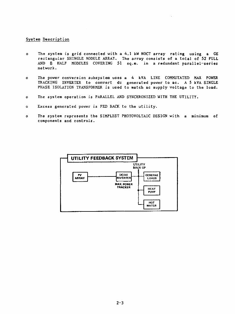
System Description
o The system is grid connected with a 4.1 kW NOCT array rating using a GE rectangular SHINGLE MODULE ARRAY. The array consists of a total of 52 FULL AND 8 HALF MODULES COVERING 51 sq.m. in a redundant parallel-series network.
o The power conversion subsystem uses TRACKING INVERTER to convert dc PHASE ISOLATION TRANSFORMER is used
a 4 kVA LINE COMMUTATED MAX POWER generated power to ac. A 5 kVA SINGLE
to match ac supply voltage to the load.
o The system operation is PARALLEL AND SYNCHRONIZED WITH THE UTILITY.
o Excess generated power is FED BACK to the utility.
o The system represents the SIMPLEST PHOTOVOLTAIC DESIGN with a minimum of components and controls.
rl UTILITY FEEDBACK SYSTEM :1-------, UTILITY BACK UP
I PV 1t-____ --1J DC/AC 11-+--11 GENERAL I ARRAY I rNVERTERj I LOADS
MAX, POWER TRACKER
2-3
H HEAT I PUMP
U HOT I I WATER
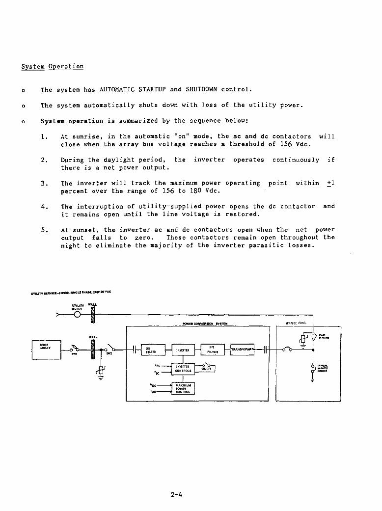
System Operation
o The system has AUTOMATIC STARTUP and SHUTDOWN control.
o The system automatically shuts down with loss of the utility power.
o System operation is summarized by the sequence below:
1. At sunrise, in the automatic "on" mode, the ac and dc contactors will close when the array bus voltage reaches a threshold of 156 Vdc.
2. During the daylight period, the inverter operates continuously if there is a net power output.
3. The inverter will track the maximum power operating point within +1 percent over the range of 156 to 180 Vdc.
4. The interruption of utility-supplied power opens the dc contact or and it remains open until the line voltage is restored.
5. At sunset, the inverter ac and dc contactors open when the net power output falls to zero. These contactors remain open throughout the night to eliminate the majority of the inverter parasitic losses.
urtUTY IERYICI.~ WIRE, S/NCiU PHAII. 24011. VAC
~OOF .-.ARAV
WALL
~~ POWEA CONVERSION rvSTeM
2-4
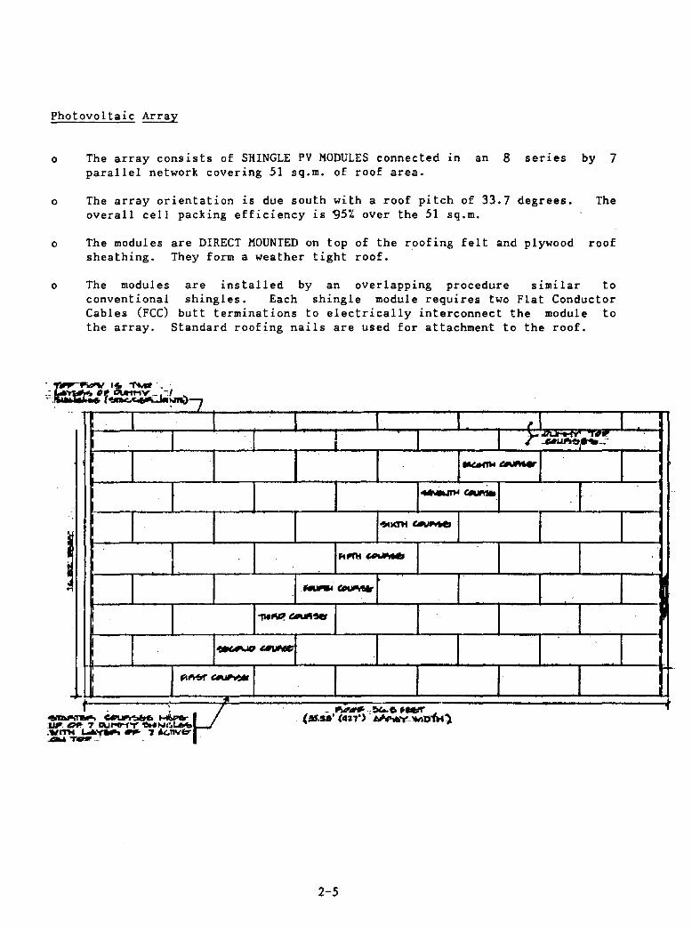
Photovoltaic Array
o The array consists of SHINGLE PV MODULES connected in an 8 series by 7 parallel network covering 51 sq.m. of roof area.
o The array orientation is due south with a roof pitch of 33.7 degrees. The overall cell packing efficiency is ~5% over the 51 sq.m.
o The modules are DIRECT MOUNTED on top of the roofing felt and plywood roof sheathing. They form a weather tight roof.
o The modules conventional Cables (FCC) the array.
... '!oIIk.
I
I
I
I
I
are installed by an overlapping procedure similar to shingles. Each shingle module requires two Flat Conductor
butt terminations to electrically interconnect the module to Standard roofing nails are used for attachment to the roof.
}7 I
I .. J I r~~I·;':!!
~eAIMer
I I I ~~
.. KTH ~l""
I I IJ\~_"" .-- C'.IIUI"o'Wr
.
I I~~~~I ~...,..
J ~Mrr~1 I t. ~,v _ ""~--~6. __
;nwo.. ~ . (M.S.' (4a7") . ",.,.. ..... 'MlriH') . 7 QJHMY'DHINI,Lb'b . L.6-,- _ 'J k.nvb' . .,....- -
2-5
f
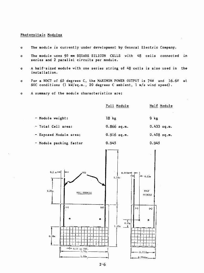
Photovoltaic Modules
o The module is currently under development by General Electric Company.
o The module uses 95 mm SQUARE SILICON CELLS with 48 cells connected in series and 2 parallel circuits per module.
o A half-sized module with one series string of 48 cells is also used in the installation.
o For a NOCT of 65 degrees C, the MAXIMUM POWER OUTPUT is 74W and 16.6V at SOC conditions (1 kW/sq.m., 20 degrees C ambient, 1 m/s wind speed).
o A summary of the module characteristics are:
Full Module Half Module
- Module weight: 18 kg 9 kg
- Total Cell area: 0.866 sq.m. 0.433 sq.m.
- Exposed Module area: 0.916 sq.m. 0.458 sq.m.
- Module packing factor 0.945 0.945
0 .1 .. -
V"'~ 1.73 OJ
0.01
'~H ..- 0.15m
0.8 6m
L FULL SHINGLE
HALF
SHINGLE
-H (+l H (+)
e - -,-!J III • 25J;:
,
I
j ~ c==-+- 0.15 em TYP.==-]
.... 1. 54m • .
1. 55m)
2-6
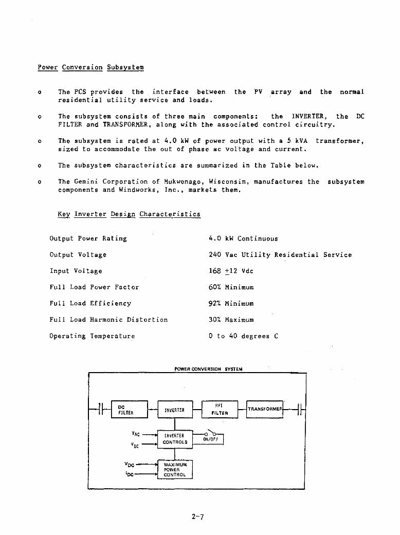
Power Conversion Subsystem
o The PCS provides the interface between the PV array and the normal residential utility service and loads.
o The subsystem consists of three main components: the INVERTER, the DC FILTER and TRANSFORMER, along with the associated control circuitry.
o The subsystem is rated at 4.0 kW of power output with a 5 kVA transformer, sized to accommodate the out of phase ac voltage and current.
o The subsystem characteristics are summarized in the Table below.
o The Gemini Corporation of Mukwonago, Wisconsin, manufactures the subsystem components and Windworks, Inc., markets them.
Key Inverter Design Characteristics
Output Power Rating 4.0 kW Continuous
Output Voltage 240 Vac utility Residential
Input Voltage 168 +12 Vdc
Full Load Power Factor 60% Minimum
Full Load Efficiency 92% Minimum
Full Load Harmonic Distortion 30% Maximum
Operating Temperature o to 40 degrees C
POWER CONVERSION SYSTEM
MAXIMUM POWER
IOc----1L5.CO~N~T!!R~O~l..J
2-7
Service

PV Interface with Utility and House Service
o Interface arrangements employ CONVENTIONAL WIRING RUNS and EQUIPMENT as much as possible to facilitate acceptance by local regulatory authorities.
o The PV array output acts as a conventional utility service; therefore, its entrance to the residence is parallel to the utility line.
o An external switch provides a means to externally disconnect the array and the PCS equipment.
o An equipment area is located in the southwest corner of the basement level.
DO
2-8
Array Sizing
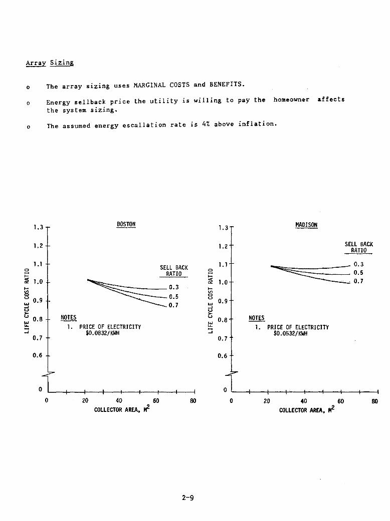
o The array sizing uses MARGINAL COSTS and BENEFITS.
o Energy sellback price the utility is willing to pay the homeowner affects the system sizing.
o The assumed energy escallation rate is 4% above inflation.
1.3 BOSTON 1.3 MADISON
1.2 1.2
1.1 1.1 0 SELL BACK .... RATIO
0
I-....
~ 1.0 ~ 1.0 I- 0.3 l-V> U') 0 <..J 0.5 0
0.9 <..J ... 0.9 .... 0.7 LLJ .... <..J <..J >-<..J 0.8 NOTES
>-<..J
0.8 NOTES LLJ "- I. PRICE OF ELECTRICITY
... .... "- 1. PRICE OF ELECTRICITY .... $0.0832/ KWH
.... 0.7
...J $0.0532/KWH 0.7
0.6 0.6
o o o 20 40 60 80 o 20 40 60
COLLECTOR AREA, ~ COLLECTOR AREA, II-
2-9
SELL BACK RATIO
80
Design Performance
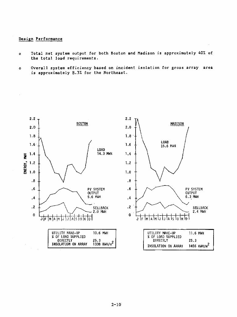
o Total net system output for both Boston and Madison is approximately 40% of the total load requirements.
o Overall system efficiency based on incident isolation for gross array area is approximately 8.3% for the Northeast.
UTILITY MAKE-UP 10.6 MWH % OF LOAD SUPPLIED
DIRECTLY 25.3 2 INSOLATION ON ARRAY 1338 KWH/m
2-10
UTILITY MAKE-UP % OF LOAD SUPPLIED
DIRECTLY INSOLATION ON ARRAY
11.6 MWH
25.3 1456 KWH/m2

System
SECTION 3
SYSTEM DESCRIPTION
Functional Description
The grid connected residential PV system for the Northeast provides
the space conditioning requirements and all conventional electrical load
requirements for an all electric home. The system consists of two major
sUbsystems: The PY solar array and the power conversion subsystems. Figure 3-1
shows a system block diagram. The 51 sq.m. solar array uses a rectangular
shingle solar cell module being developed by General Electric. The module is
selected as a next generation to the Block IV module currently available. The
array 15 wired in a redundant series/parallel matrix with a 4.1 kW rated peak
output. The array Slze 1S based on the results of marginal life cycle cost
analysis consistent with the available roof area for a passively designed house.
The photovoltaic generated power is supplied to a 4 kVA PCS which is controlled
to track the solar array maximum power operating point. A line-commutated
Gemini unit is selected based on its current availability. The PCS feeds 240 Vac
power directly to the house loads or back to the utility when excess power is
generated. The PV power is isolated from the utility by a 5 kVA transformer.
The overall system connects in parallel with the utility service to
supply the residential load. Power generated by the array in excess of
residential loads is fed back into the utility grid. With this arrangement, all
house load demands are met, no electrical storage 15 required, and all net
energy output of the photovoltaic system is used.
3-1
UTILITY BACK UP
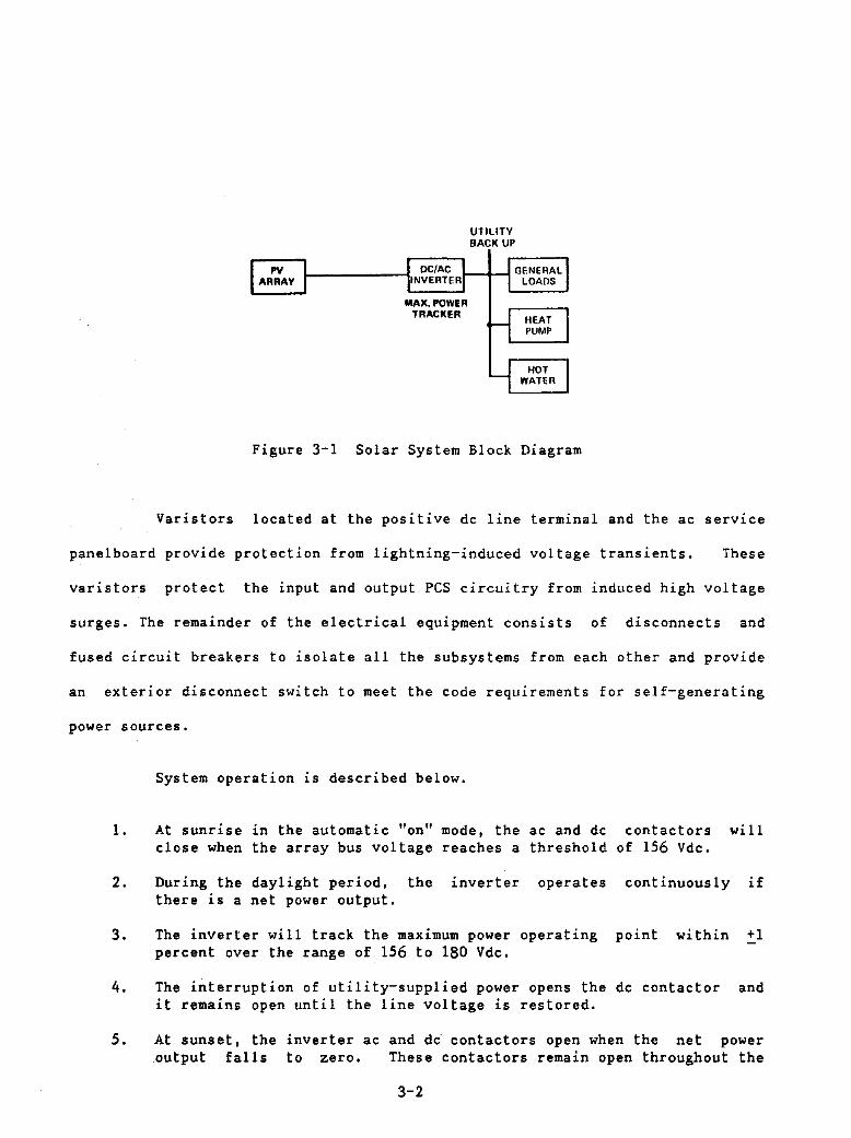
Figu~e 3-1 Solar System Block Diagram
Va~istors located at the positive dc line terminal and the ac service
panelboard p~ovide protection from lightning-induced voltage t~ansients. These
varistors p~otect the input and output pes circuitry f~om induced high voltage
surges. The ~emainder of the electrical equipment consists of disconnects and
fused ci~cuit breakers to isolate all the subsystems from each other and provide
an exterior disconnect switch to meet the code requirements for self-generating
power sources.
System operation is described below.
1. At sunrise in the automatic "on" mode, the ac and dc contactors will close when the array bus voltage reaches a threshold of 156 Vdc.
2. During the daylight period, the inverter operates continuously if there is a net power output.
3. The inverte~ will track the maximum powe~ operating point within +1 percent over the range of 156 to 180 Vdc.
4. The interruption of utility-supplied power opens the dc contact or and it remains open until the line voltage is restored.
5. At sunset, the inverter ac and dc· contactors open when the net power output falls to zero. These contactors remain open throughout the
3-2

night to eliminate the majority of the inverter parasitic losses.
The system represents the simplest photovoltaic design with a minimum
of components and controls. A key to the implementation of this design is the
acceptance of the feedback energy by the utility and the price the utility will
pay to the homeowner for this energy.
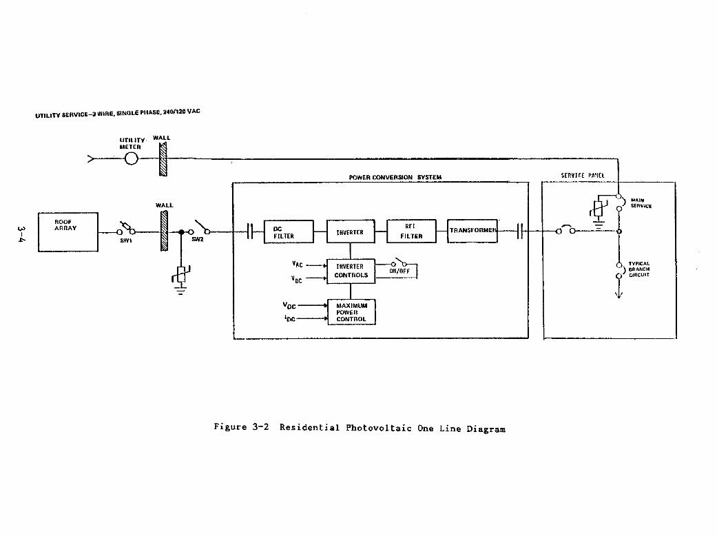
Components
A one line diagram of the system components is shown in Figure 3-2.
This section briefly describes the major functional elements of the system with
further details contained in Section 5.
Solar Array -- The solar array consists of 52 full and 8 .half shingle
modules connected electrically in a redundant series/parall.l circuit
arrangement. Eight modules are connected in series and with 7 parallei circui'ts.
The module electrical circuit terminates in positive and negativ. busbars which
are connected to cabling and run in conduit to the equipment room. The negative
busbar is grounded. The array output is 4.1 kW at NOCT conditions.
PCS -- The PCS provides the electrical interface between- the solar
array and the residential ac service. This subsystem consists of a dc input
filter, dc/ac inverter, a transformer and maximum power tracker and control
citcuits. This subsystem inverts the variable dc output of the solar array to
supply ac residential service in parallel with the utility electrical service.
Inverter The inverter is a Silicon Control Rectifier (SCR)
thyristor bridge circuit providing unidirectional current flow on the input dc
side and alternating current flow on the output ac side. It is sized at 4 kVA
and is line commutated.
3-3
V> I ~
UTlLlTV SERVICE-a WIRE, SINGLE PHASE, 240/120 VAC
ROOf ARRAV
UTlLlTV METER
'> ()
WALL
WALL
Figure 3-2
POWER CONVERSION SYSTEM SfRVIC[ PA'in
~;) MAIN SERVICE
:~II I 0 ...... 0--=--,
Residential Photovoltaic One Line Diagram
, TYPICAL ) BRANCH ? CIRCUIT
,1,
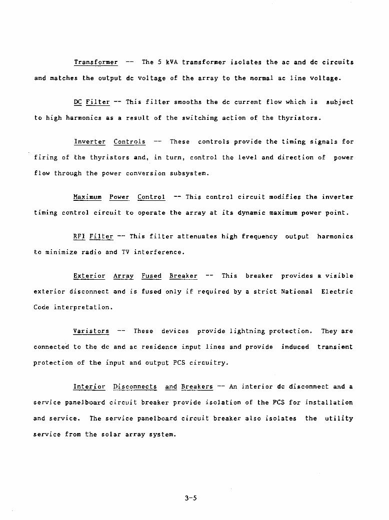
Transformer The 5 kVA transformer isolates the ac and dc circuits
and matches the output dc voltage of the array to the normal ac line voltage.
DC Filter -- This filter smooths the dc current flow which is subject
to high harmonics as a result of the switching action of the thyristors.
Inverter Controls These controls provide the timing signals for
firing of the thyristors and, in turn, control the level and direction of power
flow through the power conversion subsystem.
Maximum Power Control This control circuit modifies the inverter
timing control circuit fto operate the array at its dynamic maximum power point.
RFI Filter --- This filter attenuates high frequency output harmonics
to minimize radio and TV interference.
Exterior Array Fused Breaker This breaker provides a visible
exterior disconnect and is fused only if required by a strict National Electric
Code interpretation.
Varistors These devices provide lightning protection. They are
connected to the dc and ac residence input lines and provide induced transient
protection of the input and output PCS circuitry.
Interior Disconnects and Breakers -- An interior dc disconnect and a
service panelboard circuit breaker provide isolation of the PCS for installation
and service. The service panel board circuit breaker also isolates the utility
service from the solar array system.
3-5

System Design Requirements
A review of the environmental conditions applicable to the Northeast
region of the country, the goals for the implementation of residential PV
systems in 1986, and the specific constraints associated with residential house
designs have lead to the broad system design requirements listed in Table 3-1.
The environmental conditions listed are typical of the Northeast region. The
region has a moderate lightning environment which imposes only nominal
requirements on the design. The risk of hailstone damage in the Northeast 1S
also relatively moderate. The tempered glass cover of the rectangular shingle
module is the same as the Block IV Module which has passed hailstones tests
conducted by JPL.
regions.
The table also lists the average daily load requirements for the two
The heat pump average load requirements are based on the annual
electrical input to the heat pump required to satisfy both the space heating and
cooling requirements. Since no specific site is considered for the
installation, no specific local building, fire or electrical codes are imposed.
The design considers the general Model Code requirements appropriate for the
Northeast. The overall electrical design tries to assure safety in the normal
residential application.
The house is a new construction; therefore, the sile constraints do
not impose any significant design requirements. The house orientation is due
south and the south facing roof slopes at 33.7 degrees (8 to 12 pitch). The roof
slope is consistent with standard framing member sizes. The roof area covers 57
sq.m. and it is consistent with the aesthetic features of the house design. No
landscape shadowing or surrounding building shadowing is allowed.
3-6

System operating constraints require utility grid connection with the
PV system operating in parallel and synchronized with the utility. If utility
interruption occurs, the PV system disconnects.
3-7
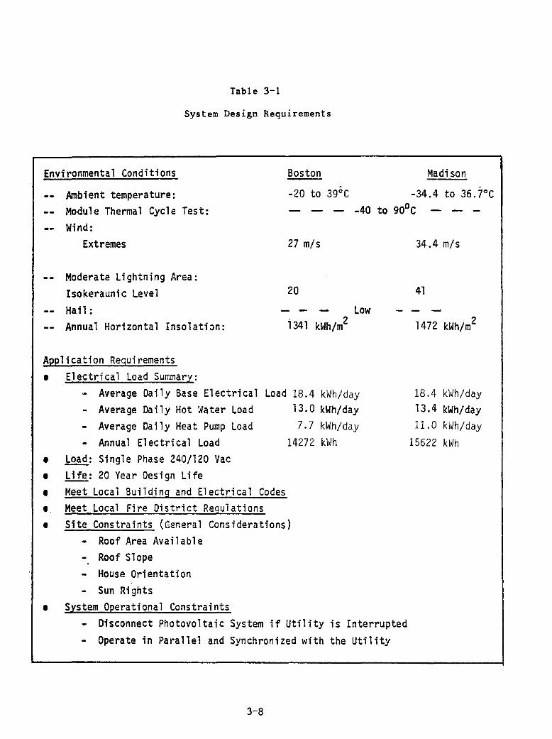
Table 3-1
System Design Requirements
Environmental Conditions Boston Madison -
Ambient temperature: -20 to 39°C -34.4 to 36.7°C Module Thermal Cycle Test: - - - -40 to 90°C - - -Wind:
Extremes
Moderate Lightning Area: Isokeraunic Level Hail: Annual Horizontal Insolation:
Application Requirements • Electrical Load Summary:
27 m/s
20
Low 1341 kWh/m2
- Average Daily Base Electrical Load 18.4 kWh/day - Average Daily Hot Water Load 13.0 kWh/day - Average Daily Heat Pump Load 7.7 kWh/day - Annual Electrical Load 14272 kWh
e Load: Single Phase 240/120 Vac e Life: 20 Year Design Life • Meet Local Building and Electrical Codes e. Meet Local Fire District Regulations • Site Constraints (General Considerations)
- Roof Area Available - Roof Slope - House Orientation - Sun Rights
• System Operational Constraints - Disconnect Photovoltaic System if Utility is Interrupted - Operate in Parallel and Synchronized with the Utility
3-8
34.4 m/s
41
1472 kWh/m2
18.4 kWh/day 13.4 kWh/day 11. 0 kWh/day
15622 kWh
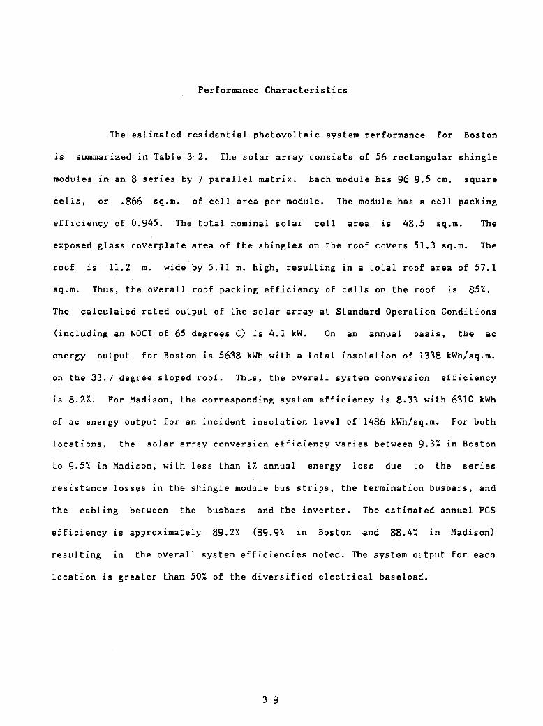
Performance Characteristics
The estimated residential photovoltaic system performance for Boston
is summarized in Table 3-2. The solar array consists of 56 rectangular shingle
modules in an 8 series by 7 parallel matrix. Each module has 96 9.5 cm, square
cells, or .866 sq.m. of cell area per module. The module has a cell packing
efficiency of 0.945. The total nominal solar cell area is 48.5 sq.m. The
exposed glass coverplate area of the shingles on the roof covers 51.3 sq.m. The
roof 1S 11.2 m. wide by 5.11 m. high, resulting in a total roof area of 57.1
sq.m. Thus, the overall roof packing efficiency of cells on the roof 1S 85%.
The calculated rated output of the solar array at Standard Operation Conditions
(including an NOCT of 65 degrees C) is 4.1 kW. On an annual basis, the ac
energy output for Boston is 5638 kWh with a total insolation of 1338 kWh/sq.m.
on the 33.7 degree sloped roof. Thus, the overall system conversion efficiency
is 8.2%. For Madison, the corresponding system efficiency is 8.31. with 0310 kWh
of ac energy output for an incident insolation level of 1486 kWh/sq.m. For both
locations, the solar array conversion efficiency varies between 9.3% in Boston
to 9.51. in Madison, with less than 11. annual energy loss due to the ser1es
resistance losses in the shingle module bus strips, the termination busbars, and
the cabling between the busbars and the inverter. The estimated annual PCS
efficiency is approximately 89.21. (89.91. in Boston and 88.41. in Madison)
resulting 1n the overall system efficiencies noted. The system output for each
location is greater than 501. of the diversified electrical baseload.
3-9
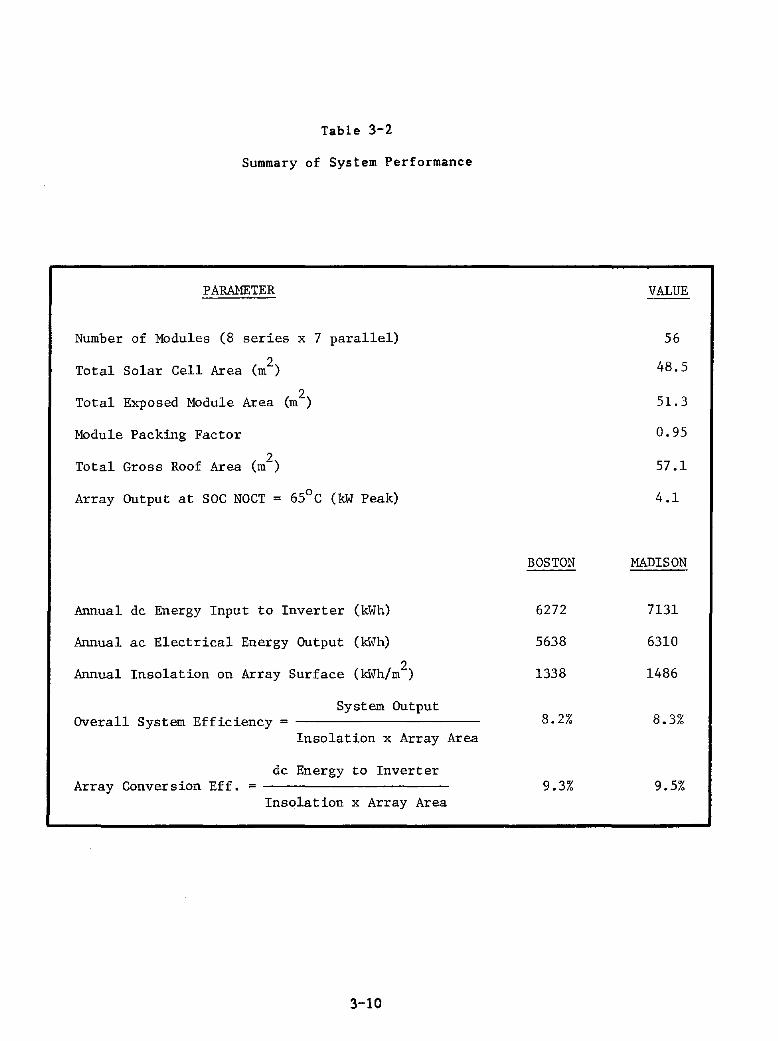
Table 3-2
Summary of System Performance
PARAMETER
Number of Modules (8 series x 7 parallel)
Total Solar Cell Area (m2)
1 d M 1 (m2) Tota Expose odu e Area
Module Packing Factor
Total Gross Roof Area (m2)
Array Output at SOC NOCT = 650 C (kW Peak)
Annual dc Energy Input to Inverter (kWh)
Annual ac Electrical Energy Output (kWh)
Annual Insolation on Array Surface (kWh/m2)
System Output Overall System Efficiency
Insolation x Array
dc Energy to Inverter Array Conversion Eff. =
Insolation x Array Area
3-10
Area
BOSTON
6272
5638
1338
8.2%
9.3%
VALUE
56
48.5
51. 3
0.95
57.1
4.1
MADISON
7131
6310
1486
8.3%
9.5%
VI LU
'" LU "-
'" <t:
...... ;:::: LU
'" '" :::> u
The I-V characteristics of the array at reference conditions are
summarized on Figure 3-3. The NOCT array output is 4.1 kWp at 132V and 31.2A. 40
30 /
20
10
o o
NOTES 1. IIRRAY CONFIGURATION
RECTANGULAR SHINGLE 8S X 7P
2. VALUES REFLECT BUS BAR AND CABLING LOSSES
3.
20
INSOLATION = 1 KW/t,(!
40 60 80
VOLTAGE. VOLTS DC
100 120
I
65°C (NOCT) _..-;<0'"\
I
I I I 132.8V
I
140
Figure 3-3 Solar Array I-V Characteristics at NOCT Conditions
Design Tradeoffs
160
System performance and economlC analyses provide the basis for
selecting the collector array size for both the Boston and Madison regions. ~ In
addition, the r-oof slope is selected based on sensitivity studies to maximize
output. The. models and input data used for all of these analyses are discussed
in Appendix D. The loads used in the analyses are reduced from previous
Northeast designs. The largest reduction occurs in the space conditioning loads.
which are reduced by 48%. The overall electrical load reduction is 14%.
Array Tilt Sensitivity
The sensitivity of collector tilt or roof slope angle to net system is
3-11
180

shown in Figure 3-4. The results indicate that the system output is maximized
at a roof slope of 34 degrees, or approximately 10 degrees less than the
latitude. The result is consistent with results for optimum array tilt angle
from previous studies. The actual design slope selected is 33.7 degrees., which
conforms to the use of standard framing techniques (8 to 12 pitch). The figure
shows that only small differences in net system output occur over the tilt angle
range of 20 degrees to 40 degrees •
. 5 Q.
~ 5500
it Iii > en
5000
o o
I~OPTIMUM TILT
I-LATITUDE
--1------I1----t1---1-t1----t1---I.--t1----11 20 25 30 35 40 45 50
COLLECTOR TILT ANGLE, DEG.
Figure 3-4 Array Tilt Angle Sensitivity in Boston
Collector Array Sizing
Array sizing is evaluated for both the Boston and Madison regions. The array
area is varied from 21 sq.m. to 64 sq.m. by maintaining 8 series modules along
the roof slant height, yielding the same system operating voltage, and adding
parallel circuits. The system performance as a function of array area is shown
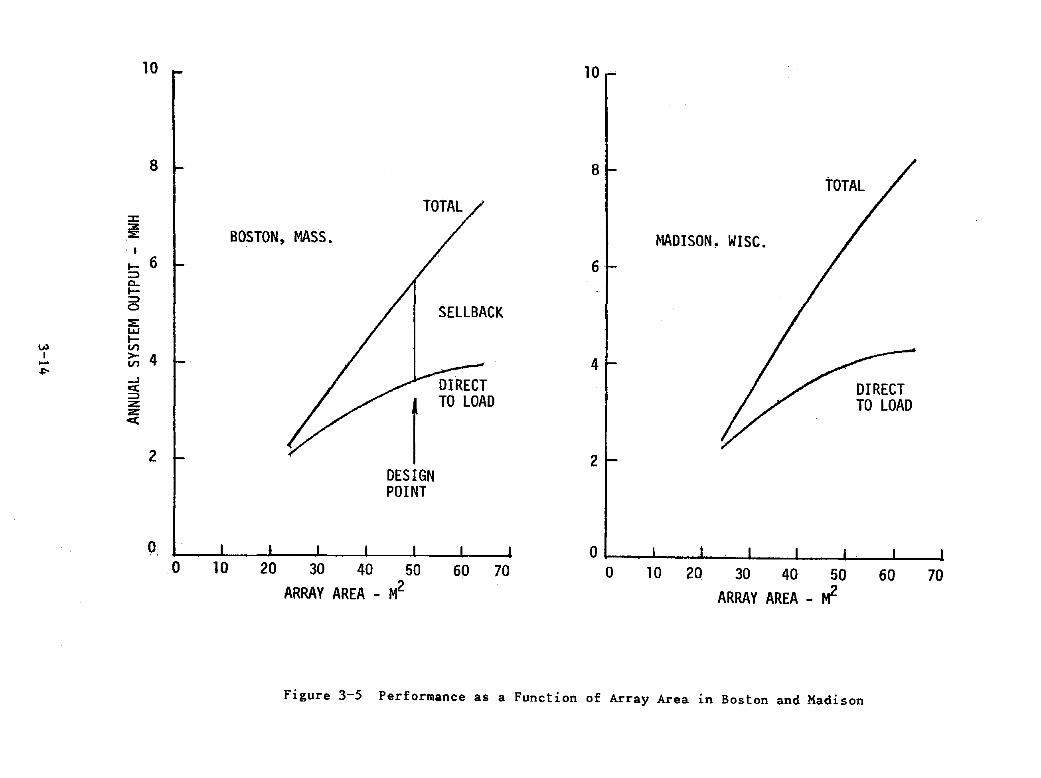
i~ Figure 3-5 for each location. The performance is defined in terms of total
energy output and the energy delivered directly to the load. The effect of
array area on system performance in Boston and Madison is quite similar. Over
the range of area variation considered, the total system output increases in
3-12
direct proportion to array area; whereas, the amount of energy delivered
directly to the load approaches a limit dictated by the magnitude and shape of
the load profile during daylight hours. Since the PV system output is
proportional to array size, and the size of the array impacts the system cost,
the effect of array size is best evaluated by means of economic parameters such
as life cycle cost ratio (LCCR). The expression for LCCR in terms of levelized
annual costs is:
LCCR LEVELIZED COST OF PV SYSTEM + LEVELIZED COST OF BACKUP ENERGY
LEVELIZED COST OF CONVENTIONAL ENERGY
The LCCR ratio can also be written in terms of the levelized annual costs (LAC)
and levelized annual benefits (LAB) as
LCCR LACsolar + (LACconv - LAB)
LACconv
LACsolar represents the levelized annual costs of the total solar system and
LACconv represents the levelized annual costs of the conventional energy for the
all-electric house in this application. The minimum LCCR value represents the
optimized economic PV system size for the application. Photovoltaic systems and
energy systems typically follow the law of diminishing returns, that is, each
additional· unit of size or capacity contributes less benefit than the preceding
unit. Whenever an additional unit, for example a square meter of PV array, can
show levelized annual savings greater than levelized annual costs, the unit can
be economically added. The minimum LCCR value represents the point where the
marginal costs equal the marginal benefits. Appendix E describes the
calculation of the economic terms and lists all economic assumptions and cost
estimates.
3-13
10 10
8 I- 8 TOTAL
TOTAL / :::t:
~ 6 l BOSTON. MASS. / ~1ADISON. WISe. 6 ::::>
c.. I-::::> 0 / SELLBACK ::E: UJ l-
V) V') I
rr 4 -~ // DIRECT
TO LOAD «
2 ~ 2 DESIGN POINT
o o 60 70
O~I--~ ____ ~~~ __ ~ ____ L-__ ~ __ ~
70 10 20 30 40 50
ARRAY AREA - M2 o 10 20. 30 40 50
ARRAY AREA _ M2 60
Figure 3-5 Performance as a Function of Array Area in Boston and Madison

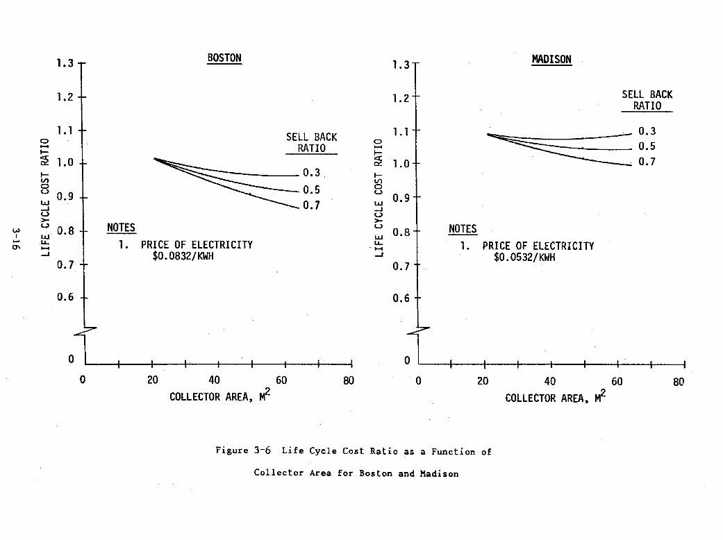
The LCCR 1S calculated for each system for three different utility
sellback energy ratios. Figure 3-6 shows these results which reflects the
regional differences of the cost of electricity and the weather between Boston
and Madison. For example, in Boston the PV system is economically viable
(LCCR<l) for array areas greater than 27 sq.m. for sellback ratios of 0.3 or
greater; whereas in Madison, sellback ratios of 0.7 or greater are required for
econom1C viability. These results assume an energy price escalation rate of 4%
above inflation.
The array area associated with the minimum LCCR also varies directly
with sellback ratio. For a sellback ratio of 0.3 in Boston, the area at minimum
LeCR is about 59 sq.m. At sellback ratios of 0.5 or greater, the area at
minimum LCCR is greater than 64 sq.m. Since the residence has an available roof
area of 57.1 sq.m., the largest rectangular shingle array configuration that the
roof can accommodate consists of 8 series by 7 parallel circuits covering 51.3
sq.m.
In Madison, the PV system is economically viable for array areas
greater than 60 sq.m. at a sellback ratio of 0.7. For smaller areas and lower
sellback ratios, the systems are not economical for the given set of costs,
energy prices and economic scenario assumed. Since the largest array which can
fit on the roof is 51.3 sq.m., a utility sellback ratio greater than 0.7 is
implied for economic viability. The assumed price of energy in each location is
the major factor contributing to the difference in economic conclusions between
Boston and Madison. In Boston, the assumed price of electricity is $.0832/kWp
(1980$); whereas in Madison, the assumed price is $0.532/kWp (Reference 3)·. The
selected system size demonstrates the economic viability of smaller-sized
systems for passively designed houses in the Northeast.
3-15
v.> I ......
0\
o -I-;:!2 lV} o U
I.I.J ....I U >U
I.I.J .1.1--....I.
1.1
o o
BOSTON
SELL BACK RATIO
~O.3 . 0.5
0.7
NOTES 1. PRICE OF ELECTRICITY
$0.0832/KWH
20 40 60
COLLECTOR AREA, M2 80
o -~ lV} o U
I.I.J ....I U >U
I.I.J 1.1-'...., ....I
NOTES 1.
o o
MADISON
SELL BACK RATIO
.~ 0.3
~ 0.5 0.7
PRICE OF ELECTRICITY $0.0532/KWH
20 40 60
COLLECTOR AREA, M2
Figure 3-6 Life Cycle Cost Ratio as a Function of
Collector Area for Boston and Madison
80
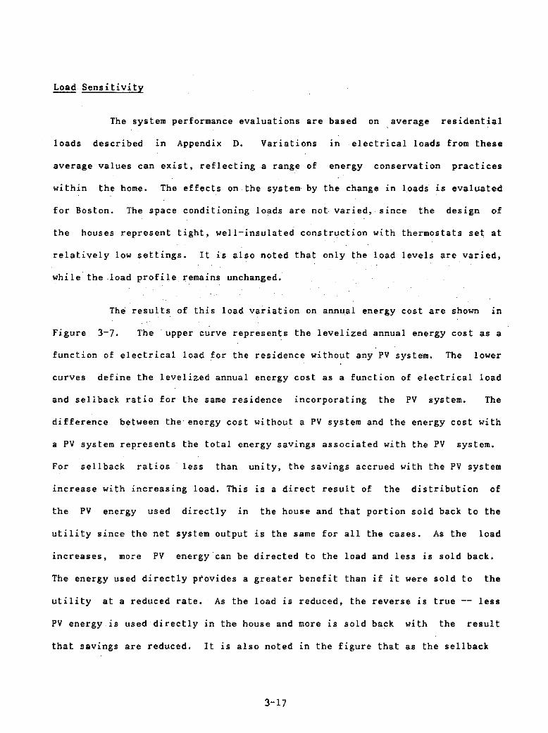
Load Sensitivity
The system performance evaluations are based on ,average residential
loads described in Appendix D. Variations in electrical loads from these
average values can exist, reflecting a range of energy conservation practices
within the home. The effects on the system by the change in loads is evaluated
for Boston. The space conditioning loads are not varied, since the design of
the houses represent tight, well-insulated construction with thermostats set at
relatively low settings. It is also noted that only the load levels are varied,
while the .load profile remains unchanged;
The resul ts of this load variation on annu,al energy cost are shown in
Figure 3-7. The' upper curve represents the levelized annual energy cost as a
function of electrical load for the residence without any PV system. The lower
curves define the levelized annual energy cost as a function of electrical load
and sellback ratio for the same residence incorporating the PV system. The
difference between the energy cost without a PV system and the energy cost with
a PV system represents the total energy savings associated with the PV system.
For sellback ratios less than unity, the savings accrued with the PV system
increase with increasing load. This is a direct result of the distribution of
the PV energy used directly in the house and that portion sold back to the
utility since the net system output is the same for all the cases. As the load
increases, more PV energy'can be directed to the load and less is sold back.
The energy used directly provides a greater benefit than if it were sold to the
utility at a reduced rate. As the load is reduced, the reverse is true less
PV energy is used directly in the house and more is sold back with the result
that savings are reduced. It is also noted in the figure that as the sellback
3-17
3000
2500
- 2000 .. lV)
8 ~ 0:::
E5 1500
o
/ /
0.5
/ /
TOTAL ENERGY COST WITHOUT SOLAR ENERGY SYSTEM
/ /
/ /
NOTES 1.
2.
TOTAL ENERGY COST WITH SOLAR ENERGY SYSTEM FOR SELLBACK RATIO
ARRAY CONFIGURATION RECTANGULAR SHINGLE
8S x2
7P 51 m
PRICE OF ELECTRICITY $0.0832/KWH
- 0.5
1.0
1.0
ACTUAL LOAD/NOMINAL LOAD 1.5
Figure 3-7 Annual Energy Cost as a Function of Electric Load
price increases, the effect of load level on the savings is diminished. For a
sellback ratio of unity, the energy cost savings associated .with the PV system
are independent of load, since the value of the energy sold back to the utility
is equal to that purchased from the utility.
For the present analysis, with the nominal design load profile, 36% of
the system output exceeds the house load demand and is sold back to the utility.
When the actual load is reduced to 50% of nominal, 57% of the system output is
sold back; whereas, when the load is increased to 150% of nominal, only 21% is
3-18

sold back to the utility. Previous studies (Reference 4) have shown that the
load variations have very little effect on LCCR at sellback ratios of SOt. or
greater.
Design Performance
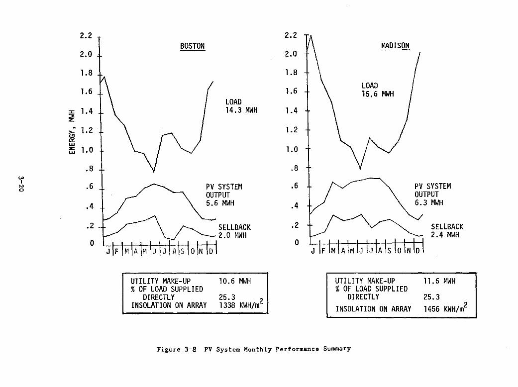
The monthly performance of the nominal design PV system is shown in
Figure 3-8 for Boston and Madison with the design collector area of 51.3 sq.m.
While the load curves represent total electrical demand, their shape clearly
reflects the difference in regional ct"imates between Boston and Madison, and the
resulting space conditioning loads. Despite the latitude similarity, Madison
generally experiences colder winters and milder summers than Boston; however,
Madison has higher levels of insolation than Boston has due to coastal cloud
cover. The overall effect of these conflicting regional factors tends to be
offsetting with respect to the percent of load supplied directly by the PV
system. In both locations, 25.3t. of the load is supplied directly by the PV
system.
3-19
w I .....
0
2.2 T BOSTON
2.0
1.8
1.6 ( LOAD
:I: 1. 4 .l.. \ 14.3 MWH ~ .; 1.2 1 \ I c.!:J a: w
t5 1.0 1 ~ ~ .8
.6 + ~ PV SYSTEM OUTPUT .4Y ~MWH
.2. ~ /"-..- C;r:IIRAr.1(
0 I I I I LLL~l I I
UTILITY MAKE-UP 10.6 MWH % OF LOAD SUPPLIED
DIRECTLY 25.3 INSOLATION ON ARRAY 1338 KWH/m2
2.2 V\ MADISON
2.0
1.8
1.6 + \ LOAD 15.6 MWH
1.4
1.2
1.0
.8
.6 Ii '\ .4
.2 + /
0
V"
"""
UTILITY MAKE-UP % OF LOAD SUPPLIED
DIRECTLY INSOLATION ON ARRAY
Figure 3-8 PV System Monthly Performance Summary
PV SYSTEM OUTPUT 6.3 MWH
SELLBACK 2.4 MWH
11.6 MWH
25.3 1456 KWH/m2

SECTION 4
HOUSE DESIGN CHARACTERISTICS
Design Features
A passively heated house has been designed by Hassdesign for the
Northeast region of the country. The house is configured to maximize the amount
of south glazing, while simultaneously providing a large rectangular roof for
the PV system and it incorporates energy conservation features.
The house has two stories and a full basement. On the first floor is
a large area containing the kitchen, dining room, staircase to the second floor,
and living room. Also on the first floor on the east end of the house is the
master bedroom suite, with a full bath, a dressing room, and a sliding glass
door facing south. On the second floor are two additional bedrooms and a bath.
Both bedrooms and the connecting hall are illuminated from clerestory windows
above the PV roof. The total floor area of the house is 157 sq.m. On the south
side of the living space is an 8.9 sq.m. greenhouse. A large brick fireplace
wall, which also provides massive storage for solar heating is located at the
core of the house, on the north side of the living room. The basement is not
subdivided, but is completely insulated around the walls and under the slab. All
of the electrical equipment for the PV array and the house panel is located in
the southwest corner of the basement. An airlock entry is provided on the north
side.
Although any of a number of energy conservation construction methods
are applicable to the building, it is designed around the innovative Acorn
Structures, Inc., building system. Hassdesign has been working for several
years with the Acorn systems, and has assisted Acorn in developing an effective
4-1

and economical method for providing a high level of energy conservation.
Because the system relies upon components trucked to the site, a
minimum of wood is used. The walls are 2 x 4 stud construction, at an average
spacing of 16 inches on center, with R-l1 insulation. On the inside of the
walls, an additional 3/4 inch of "Thermax" (trade name) foil-faced
polyisocyanurate insulation is used, yielding an extra R-factor of 6. The
combined wall section resistance value is 19. The combined cathedral ceiling R
factor is 28. This total R value includes 7 inches of fiberglass in the ceiling
(limited by a 2 inch air space under the PV array), for an R-22 value, plus an
inside layer of Thermax for an additional R-6 value. Attic space ceilings are
insulated with R-30 insulation, and R-ll insulation is used between the attic
and the adjacent bedrooms. South windows are all double glazed and the
remainder of the windows are triple glazed. Motorized draperies are used across
the entire south facade in the living and dining spaces. These draperies
provide an additional R-factor of 5 when they are closed.
Infiltration is minimized as much as possible in the design. The
Thermax interior skin provides an excellent vapor barrier and a large measure of
infiltration control. In addition, a great deal of caulking is also used.
Because the Acorn house modular sections are made from kiln lumber and are built
to tolerances of 1/16 of an inch, the building is intrinsically sol·id and tight,
resulting in a low infiltration rate.
House Plans
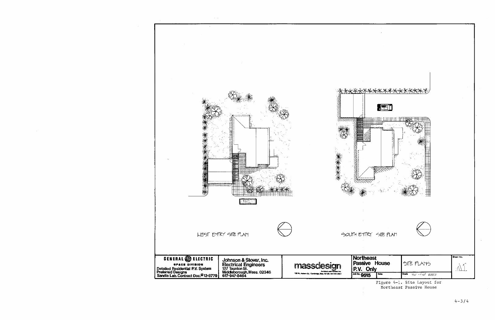
Figure 4-1 shows two possible site plan arrangements of the house, one
with an entry from the west (or east, if the plan is reversed), and the other
4-2
GEN ERAL ELECTRIC ."ao. DIYI.ION
Detailed Residential P.V. System Preferred Designs Sandia Lab. Contract Doc.#13-8779
[\1 II
Johnson & Stover, Inc. Electrical Engineers 127 Taunton St. Middleborough. Mass. 02346 617-947-8464
. ~ ..... '&
. • ....".' •. 1<.:
Figure 4-1. Site Layout for Northeast Passive House
Sheel No.
4-3/4

with an entry from the south. By strategic location of the garage and the
addition of a trellis to mark the location of the entrance, both plans can
easily be accommodated and a third, north entry design, can be incorporated.
Flexible site plans are important, since a solar house has to face south
independent of the street location.
The basement floor plan (Figure 4-2) has not been subdivided, but
provides space for a shop, recreation area, or other non-habitable space which
is valuable to a homeowner. The entire basement 15 insulated with R-ll
insulation, and the underside of the slab is insulated with R-5 insulation. All
of the electrical equipment 1S located in the southwest corner of the basement
on both the west and south walls. Both the normal electrical service and PV
service enter on the west wall and penetrate diagonally through the wood
structure, coming out of the inside of the foundation wall. The heat pump
indoor section 1S located near the fireplace foundation, at the center of the
plan, minimizing duct runs.
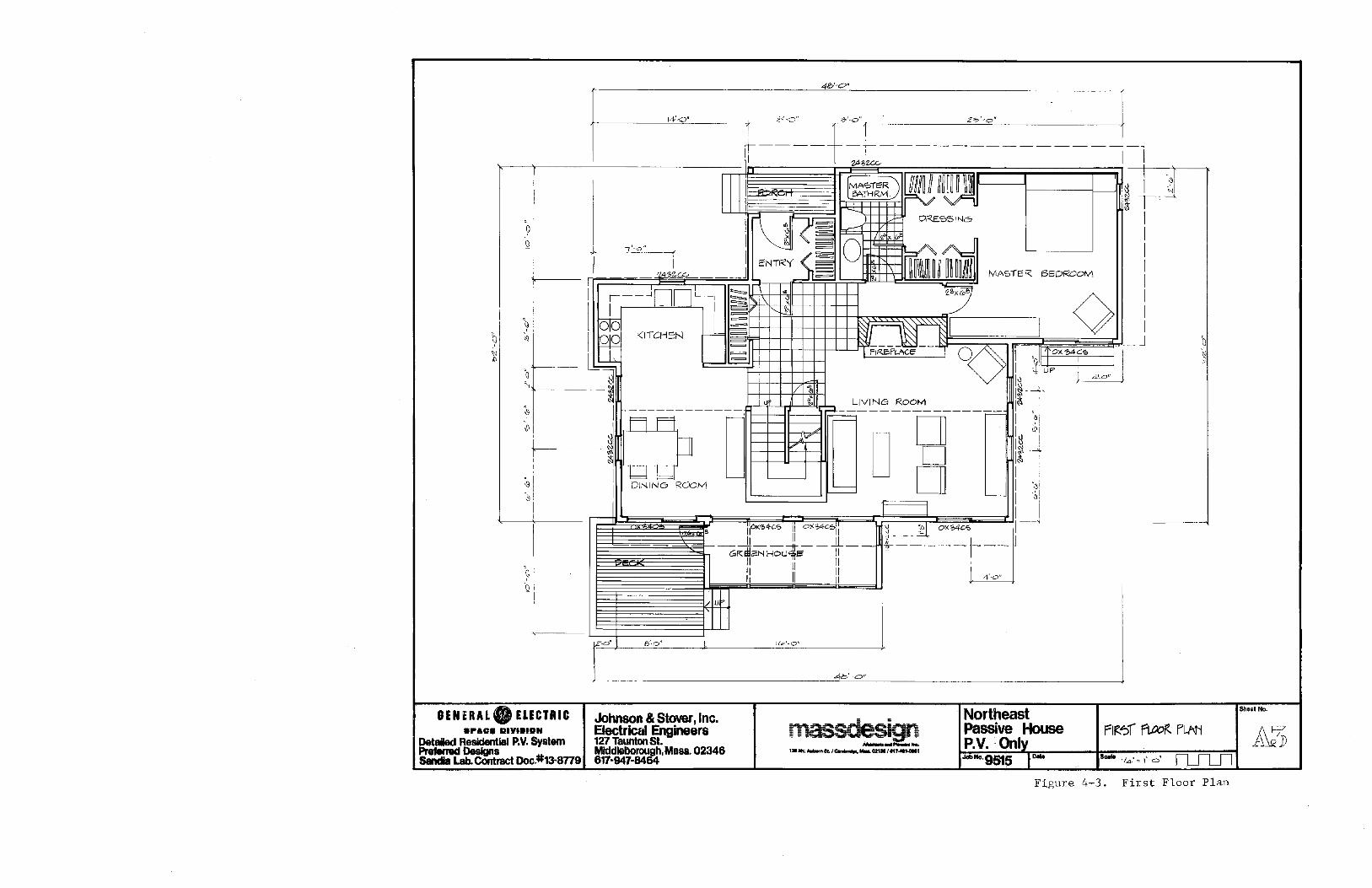
The first floor plan (Figure 4-3) is organized around a large central
entry hall. The north airlock entry vestibule has ample closet space. Inside,
the entry hall floor has quarry tile, and another large storage closet is
located to the west. This hall opens to the kitchen/dining area, the living
room, the master bathroom or the master bedroom and the stairs to the second
floor. The
first floor.
master bath has two doors, making it accessible to visitors on the
The fireplace is located at the north end of the living room so
that the flue does not need to penetrate the roof area reserved for the PV
array. It is also partially free-standing in the middle of the plan. The
kitchen is located under the ordinary 2.4 m ceiling. It is open to the dining
room which has a cathedral ceiling rising up to the second floor under the PV
4-5

array. This cathedral ceiling continues along the south wall, interrupted by
the staircase, so that half of the living room is under the low ceiling, and the
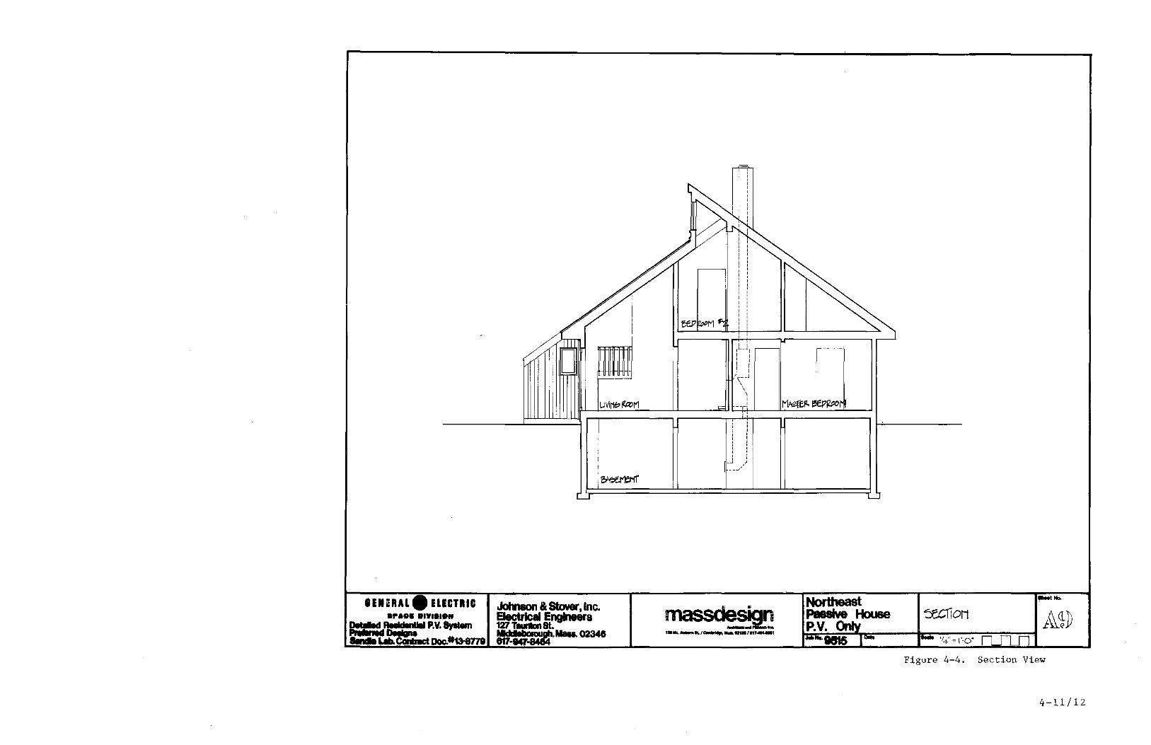
other half is under the cathedral ceiling. Figure 4-4 shows that the landing of
the staircase has a railing looking down into both the dining room and into the
living room. This feature provides an element which is highly favored by buyers.
The staircase is located close to the windows, but leaves sufficient room for a
walkway. Both the dining room and the living room are accessible to the
greenhouse, which is centered to the south of the staircase by means of sliding
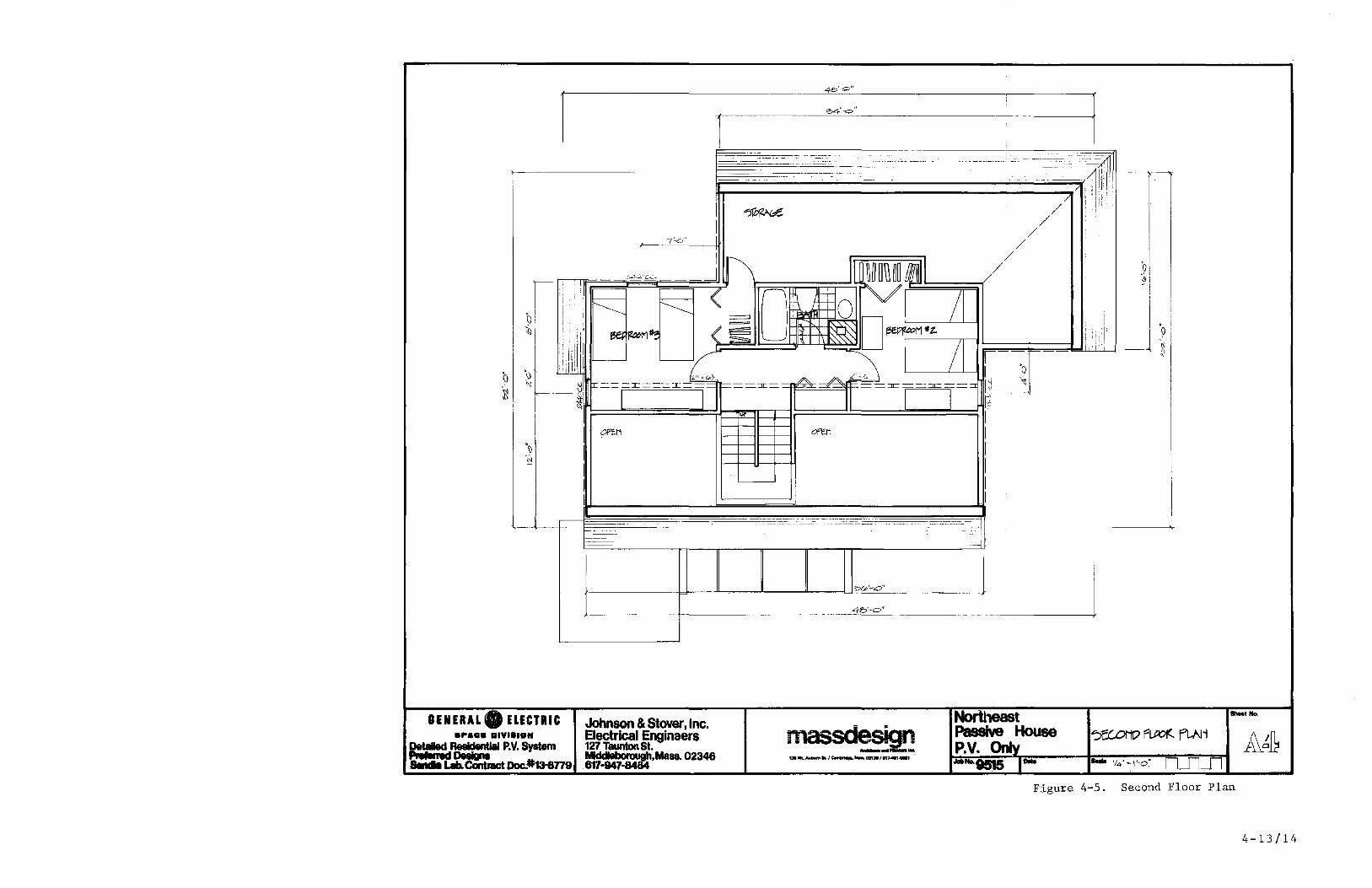
glass doors. The second floor plan (Figure 4-5) shows the layout of the
bedrooms and storage area.
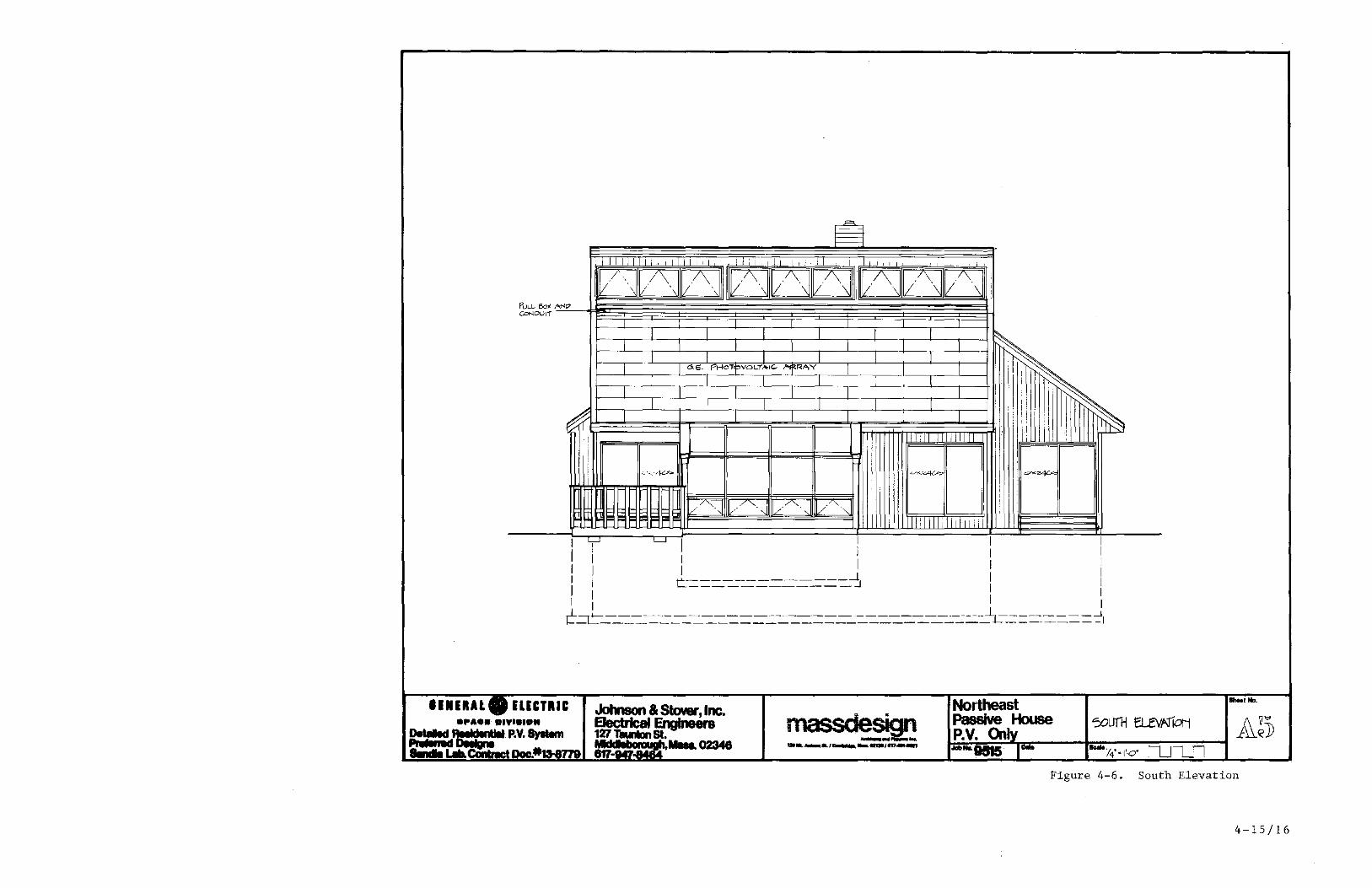
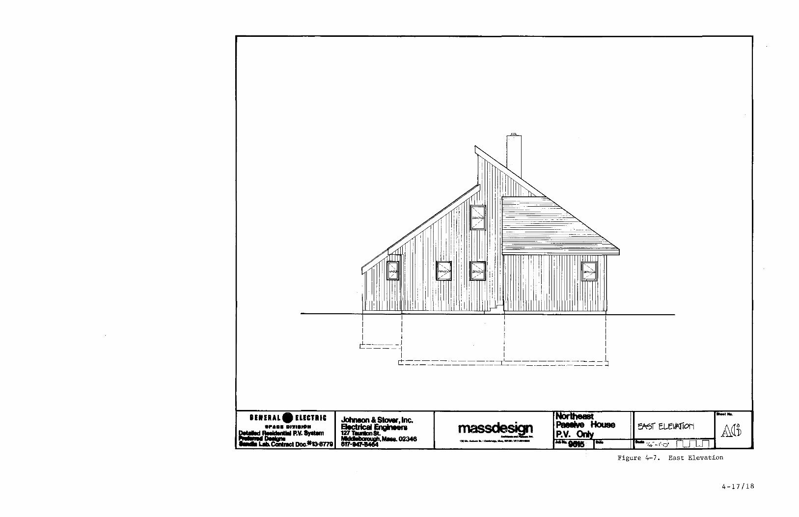
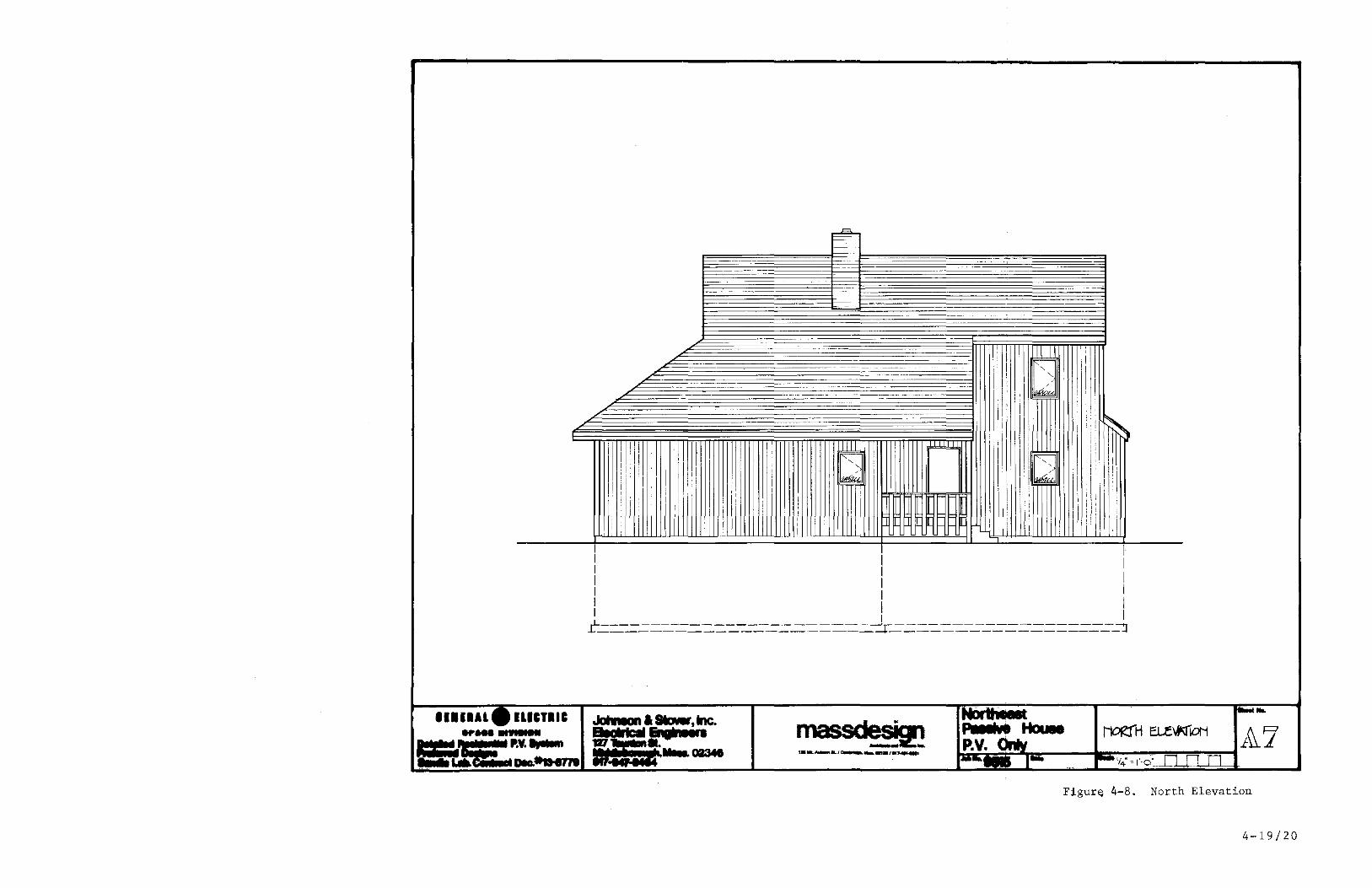
Elevation views of the house are shown in Figures 4-6 through 4-9. In
cross-section, the house features a roof with a shortened slant height. This
permits the addition of a set of clerestory windows at the top of the PV roof.
By somewhat complicated framing, the second story is placed under the high part
of the section, and receives the benefit of the clerestory windows. The long
north roof returns back to the first level, forming a large attic over the
master bedroom, master bath, and entry areas. At the northwest corner of the
building, the long sloping north roof is cut away to expose a two-story high
section. The entry occurs at this point, and is designed for ready access from
the north and west (and from the east if the plan is reversed). By extending a
covered walkway, or trellis, out beyond the end of the plan, it is also possible
to enter the building from the south. These options are shown on the site plan.
4-6

4&'·,,"
l' -/'-------'--1 -----1' II~ ,=--=-~=---=--_=T"rr;:;:;;:;:;~~~;:;:;;:;:;;:;:;~I---+----ci':-
\I' I I INSUt-ATiON Y
I 1\-. I I if-WOOD 9TU~
'<------r---;;;~~ -------------------.f
t I <fl-o" I r;=
1/-/--- rr.;:;;:;;:;;:;;:;;:;;:;;:;;:;~~: ====== ~S1E'E:L. 8EAM ~-r-,'PJCAL.- ~~~ COl.., :=
GENERAL ELECTRIC .... 0. DIY'.ION
Detailed Residential P.V. System Preferred ~s SandIa Lab. Contract Doc.#13-S779
o I
/o1.c/ I ---_. --'-----,(
= = = - -- -- -- --_. _C'I"-4"~~",-= fO~ =0:: 0reE~ BEjO,M ~ = = =
'Johnson & Stover, Inc. Electrical Engineers 127 Taunton St. Middleborough,Mass.02346 617-947-8464
~~ 5: =#11£
m "!lliissaeSl= ." •• g;; - ~I~ ........... "--:1 ...
1.1tt. ~tt./~ •.... 02131/617 .... ' ... '
j1t .. o" I
~,
II
Northeast Passive House P.V. Only JobNo.9Sl5 10 ...
I
r
4S5 r:¥IG<. e-4 ft'!e Ke"f ,0 NUMee~
Figure 4-2. Basement Plan
4-7/8
, o Q
GEN UAL. ELECTRIC .f'AVa DIYI.IDN
Detailed Residential P.V. System Prefemld DesIgns SIndIa Lab. Contract Doc.#13-8779
14'-01
T
•
u
£'-0" e/-o" l
Johnson & Stover, Inc. Electrical Engineers 127 Taunton St. Mlddleborough,Mass.02346 617-947-8464
ii""MG'S II O~34C5ii
II II II GRdiE"NHOule II
II II II II II Ii
i&:>'-O"
.48-0"
massdesign ...................... 1311tt;.......,,&./~ ..... 0213IJf17 ........ ,
Northeast Passive House P.V. Only
Do,.
Figure 4-3. First Floor Plan
ShIel No.
UIURAL • ELECTRIC .pall ••• Y ••• OII ==.n .. 'tw ..... P.V. 8yttem
-- Dnla .. 8 ..... LaCOnlnlct Doc.#13-8771
Johnson & Stover, Inc, ElectrIcal Engineers 127 TOUItDn St. ,..l1li a::'8'Mau, 02348 817·...,
~~~ ~IF~! 1.Mt.,...,.. .. /~ ....... /m ....... f
Northeast Pa8aw, House s::.cIiOM 1~~}) ~~~.V~.~~~ _____ ~~~ _____ -=~~~
Figure 4-4. Section View
4-11/12
1
4b'-O"
:::.4'-0 " I 1 - - ,- . , . . ... .. __ .. .
, ,. ....... _. , , . __ .. . .... ····,,1111 . - -_.- -- , ..
_ .. - . '" , . . ~ 1 irI' I
I "')l/;>~ // I\i~'
I / 7:...0"
/ 1 / I
I f\ / I
--.J Il[M~~~~ II / '0 ' , "".: c...c-- ~I I:' ~ F:::::: < O~ o I /
-I , I
I . I • I 1 Qi
~~M~ (~ ~I . i I I\~ D~MjlZ. !, :
j 'li'll :,'):, " -1-~
v--- ~ ~.'S I I ~
:9 ,.illJl Q &" ,"; "'" I '0
~, "" '~~I tr=-i JC---
I rJt--=::n: I =--=---::::J I) " I
-.-
, I *1
I~
I I
I Cf'fcH 0ftf1 I
'0 I 1 -;,. I
1
I 1
I I I - - .. ---- _ ... ,-,
. -- . ,- , , ,. -'--~ ,
-
1 ,
:Q(p'-c:f
4b"O"
IUNEUL. ELECTRIC Johnson & Stover,lnc. Northeast _I No.
.... a. IIIYI.IIIN Electrical Enginaers massd!.~ Passive House "'X.C.OfiD f~ f'L.Ni 1\l~11 =::c.R88Ident1a1 P.V. System 127 Taunton St. P.V. Only ~.Ma88.02346 DI!ignI 1.MLAubllmk/~""'on.',,'J"'''' I_ fLf1.n ..... Lab.CcIntract Doc.#13-8779 617-947- .loll No. 9515 - '/4'" "'0:
Figure 4-5. Second Floor Plan
4-13/14
02348
.L I I UilWl I Wl..U.i
massde' . - -~ __ ....... IL/~ .... .,./.".....,
Northeast Passive House P.V.
No.
Figure 4-6. South Elevation
4-15/16
I I I I I I ..L _____ I I L _____ I
1 I I I -----------:1 ~~~~~-~~~==-~-------------
1 .............. I~ ..... DIt.I ... 741...,
Figure 4-7. East Elevation
4-17/18
c=.
- -
IIIII ! I1III1 ' II I I
I I I , I
J II I , I I
,
.I i
UleTl.e JoINonas.a.,1nc. ., .... ,. 1Z1 •. ...... 02341
... -
·
I~ !
II
i I
II II ii= fL
rnasscle.qD I -=':iZ ... l._.-...... ... /~ ...... ,.,.......
Fi= r-
Figur~ 4-8. North Elevation
4-19/20
I I I I I I I L _____ J I I I 1----- .=i_
II I I I I __ 1 ____ - ______ I ___________ ~ C--J _____ ~ ______ J--__________ ~
massde . -~
- .... (\ <(1) l~<1D
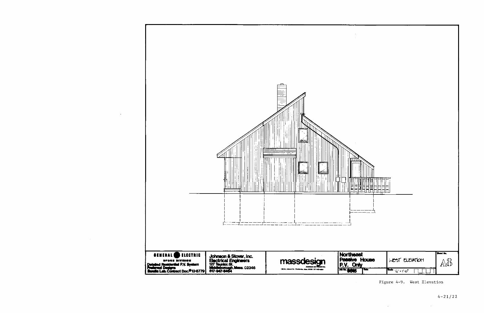
Figure 4-9. West Elevation
4-21/22

Description of the Passive Solar Heating System
Figure 4-10 illustrates the four passive and auxilliary heating and
cooling air flow patterns.
1. Storing Heat from the Greenhouse Solar energy penetrating the glazing of the greenhouse can heat the greenhouse, and be stored or directed to the living space of the house. There is an insulated thermal storage slab, in the greenhouse proper, which provides part of the desirable storage. In addition, overheated air from the greenhouse is directed into the far side of the basement by a small supply fan whenever the greenhouse overheats. These fans are under the control of a high limit thermostat located near the top of the greenhouse. This design uses the existing mass in the insulated floor slab of the basement, the finished materials of the basement, and the chimney foundation to absorb any overheating from the greenhouse instead of providing massive construction between the house and the greenhouse. This provides two benefits: (1) a warm basement; and (2) heat gain to the main living space from the first floor (as opposed to a loss if the basement were cold). This approach appears cheaper than providing a dedicated storage device 1n the basement for the greenhouse.
2. Direct Gain with Intrinsic Storage -- The normal passive operating mode of the house involves direct gain through the south glass with distribution into all major spaces in the house. While no special storage mass is included in the living space, the chimney mass is available to receive indirect radiation; and the framing, gypsym board and flooring provide a modest amount of storage. Aside from the greenhouse (which can receive much more heat than it needs during a sunny day), the rest of the house is "sun tempered" rather than passively solar heated. This means that only a modest amount of south glazing is included, sized to the modest amount of storage available in the intrinsic construction of the building. Much of the direct gain in the living spaces comes, secondarily, through the greenhouse by way of the sliding glass doors between the greenhouse and the living spaces.
3. Auxiliary Heating from the Heat Pump Whenever passive gain is unavailable or inadequate to satisfy the heating demand for the house, the heat pump operates in a normal fashion. In addition, the heat pump can be run without the coil, using the fan to redistribute air throughout the building during periods of direct gain. This further extends the effectiveness of the direct gain solar heating, as it allows all of the intrinsic structure mass to store excess passive gain. This process is not as efficient as direct storage 1n massive interior walls or trombe walls, however, the high cost and construction difficulties involved in building with these massive walls offsets their advantages. This redistribution approach is a simple means of increasing the solar gain with no added cost since the distribution system for the heat pump is already in place.
4-23

4. Natural Cooling -- The house is designed to provide the maximum amount of natural cooling and minimize the operation of the heat pump during the summer. First, the sloping glass in the greenhouse is permanently covered during hot weather with an insulating cover, either outside (taking account of the high maintenance requirement) or inside the glazing. Inside the glazing, the cover will either have a white or reflective outer surface to avoid excess buildup of heat underneath the double glazing. In the house, the primary cooling device is the row of awning windows forming a clerestory. The high clerestory windows induce a substantial flow of air through the house, since the amount of thermal siphoning ventilation is proportional to the height differential between the intake and discharge of air. These windows are controlled manually by the owner. Typically, the windows are open all the time during the warm weather and closed only when it gets cool or is extremely hot and humid during the day. The basement is also included in the ventilation of the house. Operating the distribution system without the coil allows the mass in the basement to function as a heat sink and help absorb some of the excess heat during the day. This will keep the house comfortable until cool night air is introduced by thermal siphoned ventilation. Backup cooling 1S
provided by the heat pump.
Appendix D describes calculated estimates for the reduced heating
loads due to the passive house design features.
4-24
GENERAL. ELECTRIC ."aol DIYI.IOH
Detailed Residential P.V. System Preferred Designs SandIa Lab. Cootract Doc.#13-8779
Johnson & Stover, Inc. Electrical Engineers 127 Taunton 5t. Middleborough •. lllass.02346 617-947-8464
= • il'T!I=:!;r~,NOC';N~ ~ i ~:;-~--..;;;.;;;q~i1 ;; .......... "'--" ..... 138h1l._SLlc...or ........ D2138/1117 .. 1I1.e:.l
Sheel No.
Northeast Of'tiZf1iN0 Mo~ Passive House jf\. In/n ~P~.V~.~cm~I~~ __ ~ ________ ~ ~nn J~No, 9515 ' 0.,. l?/so 5,.,. He "'::<:AiL
Figure 4-10. Operating Modes for Passive and Auxiliary Heating
and Cooling
4-25/26

The fireplace is included in the design primarily because of the
intense market demand for fireplaces in a house of this price range. A wood
stove could be substituted for the fireplace with no change in the design. Most
of the chimney mass is interior to the house, with only the minimum chimney
extending above the roof. A gasketed flue top damper operated by solenoid 1S
included in the chimney to trap the air in the chimney and prevent the chimney
from being cooled by convected loss up the flue. The heat that has accumulated
in the chimney mass is then free to discharge into the space by radiation. By
covering the embers of a fire with a tight fitting metal hood, it is possible to
close the damper immediately after leaving th~ room, without having to leave the
flue open until all the embers are cooled. This strategy also greatly increases
the efficiency of an ordinary fireplace. If a wood stove were used, it would be
likely that the chimney would consist of a metal flue extending above the roof.
Masonry would be added around the flue on the inside of the building to provide
the desirable thermal mass. While the flue top damper is not an ideal solution
to the fireplace chimney problem, it does go a long way toward reducing
convected losses during cool-down periods.
4-27

Module
SECTION 5
SUBSYSTEM SPECIFICATIONS
Solar Array
The residential solar array design for this Northeast application uses
the GE rectangular shingle module in an 8 series by 7 parallel circuit
configuration. The modules are presently under development by GE. These
modules utilize a 9.4 cm. square silicon solar cell. The shingle modules are
shown in detail in Figure 5-1. There are two module types, a full size module
and a half size module. These physically different shingles are manufactured to
the same specifications, except that the full module is twice the power at the
same voltage as the palf module. The solar cell network of the full module
consists of 2 parallel connected rows of 48 cells wired in series. This
constitutes a total of 96 solar cells per full module. On the other hand, the
solar cell network of the half module, consists of 48 series connected cells.
The construction details of the shingle modules are discussed in appendix F.
This shi'ngle design is markedly different from the Block IV design
described in Reference 4. The current shingle interconnection scheme uses the
UL-approved AMP, Inc., flat-conductor cable (FCC) under carpet interconnecting
system. The use of this flat conductor cable and patented crimp connector (see
Figure 5-2) as the two output terminals of the module permits the reliable
series parallel interconnection of modules on the roof at a lower total
installed cost when compared to the original JPL Block IV design, which employed
copper foil conductors within each module. The four terminals of this previous
design were interconnected with machine screws to complete the series/parallel
5-1
0.1 m [- FCC
~ 1. 73
--0.04
m
.. I..f--- -- 0.15m
0.86m
L FULL SHINGLE
HALF
SHINGLE
H (+) H (+)
® ® ,- --r -i!) • 0.25 111
1.3 7m J
I -.-
r-0.58m l-
L i--
, '-- -
~ "",,,,41--+-__ 0 ._15_c~.~!. ~ I ~ ______ 1.55m) ______ ~
ILo'771.6.~1 ~.7748ml-J
Figure 5-1. GE Square Shingle Design
5-2
matrix on the roof surface. This AMP interconnection system also provides the
ability to accommodate relatively larger variations in the placement of the
modules on the roof and simplifies the module removal and placement procedure as
will be explained later in the Array Installation section.
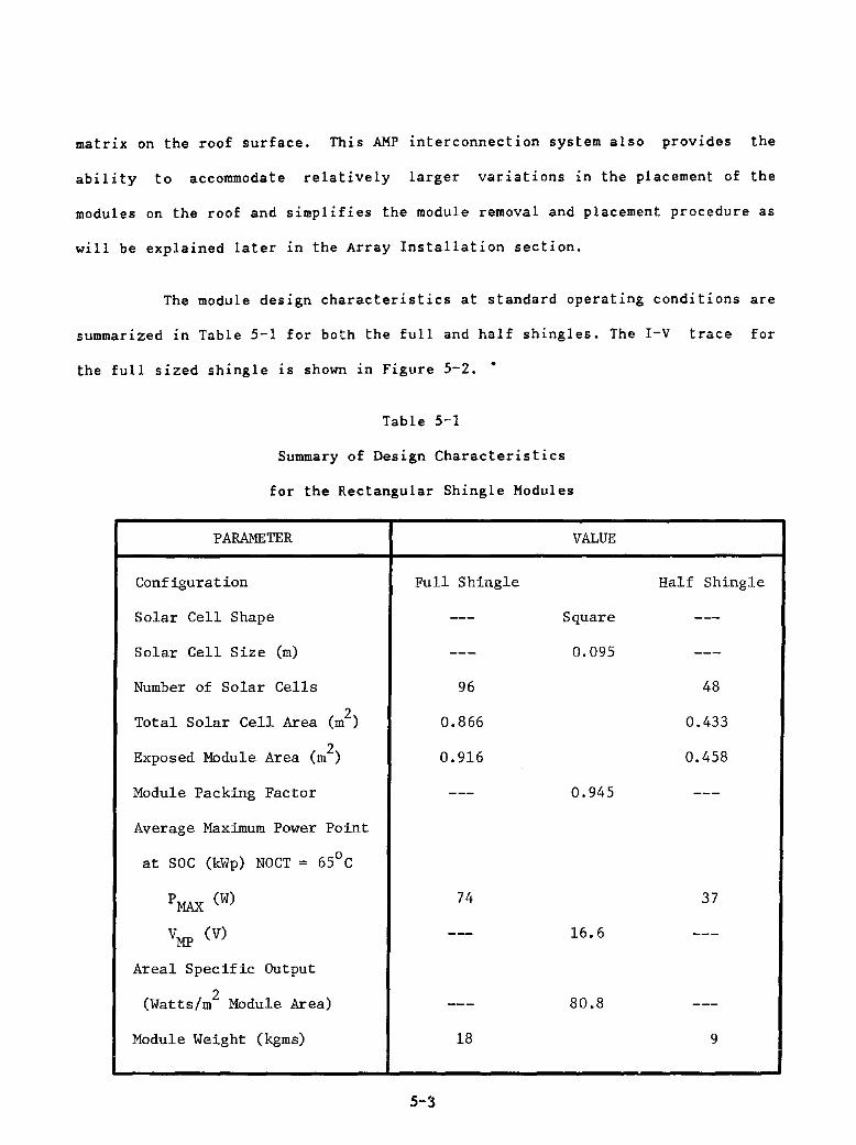
The module design characteristics at standard operating conditions are
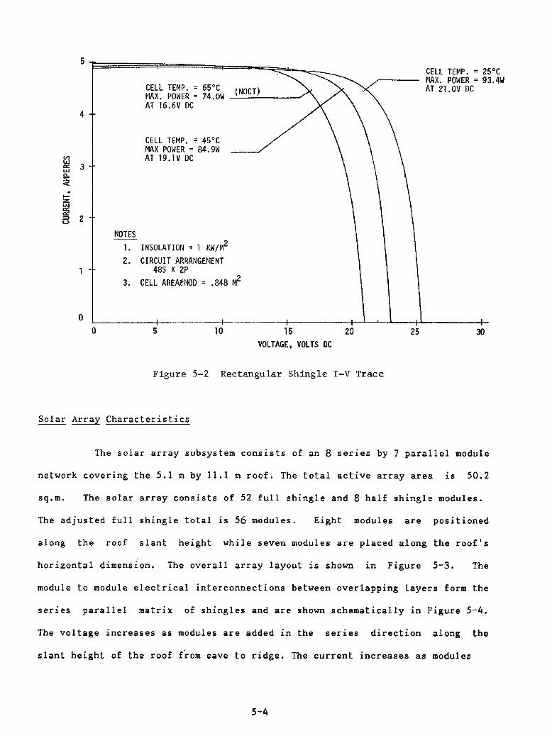
summarized in Table 5-1 for both the full and half shingles. The I-V trace for
the full sized shingle is shown in Figure 5-2 ••
Table 5-1
Summary of Design Characteristics
for the Rectangular Shingle Modules
PARAMETER
Configuration
Solar Cell Shape
Solar Cell Size (m)
Number of Solar Cells
2 Total Solar Cell Area (m )
2 Exposed Module Area (m )
Module Packing Factor
Average Maximum Power Point
at SOC (kWp) NOCT = 650 C
PMAX
(W)
VMP
(V)
Areal Specific Output
2 (Watts/m Module Area)
Module Weight (kgms)
VALUE
Full Shingle
Square
0.095
96
0.866
0.916
0.945
74
16.6
80.8
18
5-3
Half Shingle
48
0.433
0.458
37
9
Iz: UI
"" ""
4
13 2
o
NOTES 1.
CELL TEMP. = 65°C ) ~IAX. POWER = 74.0W -'-IN_O_CT...:.-__ --' AT 16.6V DC
CELL THIP. 0; 45°C MAX POWER = 84.9W AT 19.1V DC
INSOLATION = 1 KW/M2
2. CIRCUIT ARRANGEHENT 485 X 2P
3. CELL AREMf>1OD = .848 H2
CELL TEHP. = 25°C t1AX. POWER = 93.4W AT 21.0V DC
'-------+-----------b--------t------t--'--~-1--_t''------1_
o 5 10 15 20 25 30 VOLTAGE, VOLTS DC
Figure 5-2 Rectangular Shingle I-V Trace
Solar Array Characteristics
The solar array subsystem consists of an 8 series by 7 parallel module
network covering the 5.1 m by 11.1 m roof. The total active array area is 50.2
sq.m. The solar array consists of 52 full shingle and 8 half shingle modules.
The adjusted full shingle total is 56 modules. Eight modules are positioned
along the roof slant height while seven modules are placed along the roof's
horizontal dimension. The overall array layout is shown 1n Figure 5-3. The
module to module electrical interconnections between overlapping layers form the
series parallel matrix of shingles and are shown schematically in Figure 5-4.
The voltage increases as modules are added in the series direction along the
slant height of the roof from eave to ridge. The current increases as modules
5-4
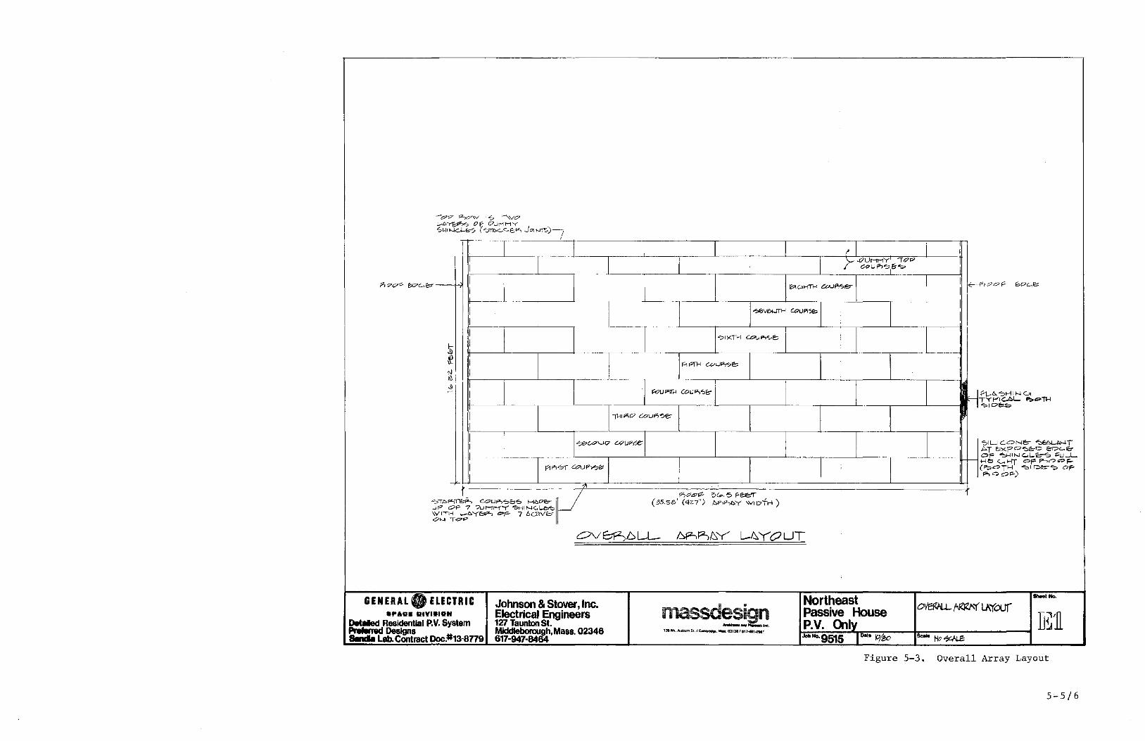
-;,9t7 s;;z..,O\V ? --'M? ...... .c~e;, of I7L.!MMY ""~I"-lCJ-.."'7 ('"Tbc..C,E;"" JOII .. rrS)i
I i' I
I I ;-- .. !7UMMY lOP
CC>UP,~I~~
P, 7<71" We..". I
\
i1:'IC->HTH eouP,.,e- I <c---P> c? 0 f" "'(;7<..,,,, I I
I T """'~ CoUP\5", I I I
I o?lKTH COU..,,,,e:; I
$ I
& I ~ r"rH CQU"t?e:; I t-l I I III -S
I i I I'oUI">1H (oW"'''''E:- ~_-+f'1...6, -:,H INc." TYPICAL.. f;""n-< ""='lDc.b
I -n-+I ""17 CouFl'5€::
I --I
I "",,(.Our;;> CQUI">SC I '::>ILICONe:>- ~I>NT I AT "",<p=~o E:-Dc..E::-
OF ~IN<:"L.1<:::-"'> l=uL.L. r- He:>1 c.... >-IT OF P-,<?=F-
I P1 "'01' c",ul"l?,," I (P:>C?T>-I -:'1 ~"""? Oi<"
I F'-IQc?~)
-"
1_ ~ 1'70.<7"" ? (". '5 F- E:e1r 1 ~TDfZ)~ c..oUP>"::;>b'o HI:::.I7e::;- (35.58' (4Z7") kR-o"",,,,y WIDTH) uP" OF- 7 Dut-rr-rY ~HIN~~ \VITI-! L-",ye:.P-> ""F- 7 bcnv& I 01--1- TG7P
ov8P,.6LL- t:,p-..,P,f:::, Y L-/::,.YOUT
GENERAL. ELECTRIC Northeast _,110. Johnson & Stover, Inc.
ma.S&.e~s:an ~~",(t..\"'(our ..... v. DIYI.IGN Electrical Engineers ~ Ii • - ." ~ Passive House ]~/n Det8IIed Residential P.V, System 127 Taunton St. ~"'==:"'I":' P.V. <XIly
I~Deslgns Middleboroud!r' Mass. 02346 138 MI ....... m SI. /~. MIlL 02138/ e17410011\
IDa!· ~/eo ..... Lab. Contract Doc.#13-8779 617-947-84 Job 110. 9515 9c:oIo Ho~
Figure 5-3. Overall Array Layout
5'-5/6

+
NEGRTlVr; Sus
Figure 5-4 Solar Array Module Interconnection Electrical Schematic
are added in the parallel direction across the length of the roof from gable to
gable. The negative terminations at the eave and the positive terminations at
the ridge for each solar cell circuit are attached to the FCC bus bars running
:he length of the roof.
Each module has a SOC average maximum power output of 74 W at 16.6 Vdc
at an NOCT of 65 degrees C. Thus, the total maximum power output for the array
subsystem is 4144 W. The array voltage at maximum power output 1S 132.8 Vdc.
The I-V characteristic curve for the array subsystem was previously shown 1n
Figure 3-3.
Solar Array Installation
The GE shingle module 1S classified as a direct mount system
5-7

installation. It is designed to serve as a weather-tight element and provide PV
dc power. A PV array constructed with these modules as building blocks becomes
the roof of the residence and displaces the need for conventional asphalt
shingles. Figure 5-5 shows the overlapping installation of the shingles in a
schematic diagram. Appendix C lists some general safety notes to follow during
system installation.
Before shingle installation, the plywood roof sheathing is prepared
with a Type 30 roofing felt, as in a typical residential asphalt shingled roof.
A horizontal and vertical network of #10 AWG FCC cable is placed on top of the
felt in accordance with the spacing requirements specified in Figures 5-6 and
5-7. The positive and negative buses each consist of three runs of FCC cable
connected at intermediate points developing a tapered busbar effect. The
negative busbar is folded and run up the left side of the roof to the roof ridge
as shown in Figure 5-6.
All the FCC cable rows can be secured to the roofing felt with duct
tape strips in their proper alignment prior to erection of the shingles; or they
can be placed sequentially as the installation progresses up the roof.
Dimensions of FCC cable rows detailed in Figure 5-6 are to the FCC center lines.
The placement of the cables does not have to be held exactly to the dimensions.
The cable row dimensions are identified as a guide so that shingle attaching
nails will clear the FCC cable.
5-8
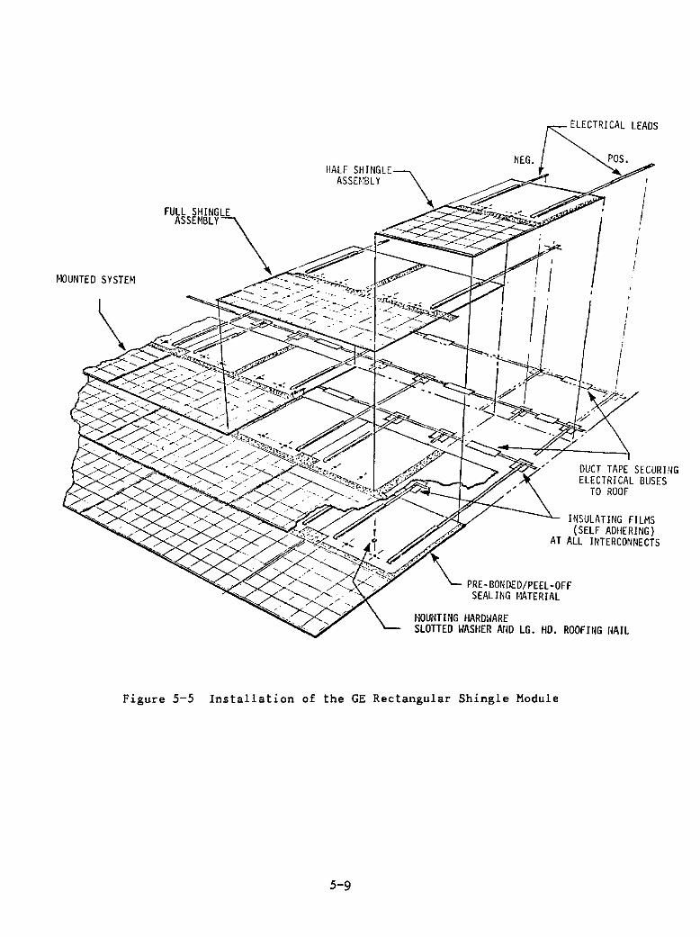
~10UNTED SYSTHI
Figure 5-5 Installation of the
5-9
I I
i
I
DUCT TAPE SECURING ELECTRICAL BUSES
TO ROOF
INSULATING FILMS (SELF ADHERING)
AT ALL INTERCONNECTS
PRE-BONDED/PEEL-OFF SEALlNG l·!ATERIAL
HOUNTING HARm~ARE lG HD. ROOFING flAIL SLOTTED I~ASIlER ArID •
I Shingle Module GE Rectangu ar

The shingle installation begins with a dummy course of shingles placed
at the roof's eave in the manner shown in Figure 5-8. Dummy shingles are
electrically inactive shingles to complete a weather tight installation. They
are fabricated with the exact same dimensions as the full and half sized active
shingles. The dummy shingles are attached to the roof sheathing by nailing
through the substrate at two marked locations, per shingle, with roofing nails.
Following the dummy shingle course installation, seven full modules are overlaid
constituting the first active row.
The active shingles are attached to the roof sheathing by use of a
special split washer under the roofing nailhead as shown in the details of
Figure 5-9. Two through holes which are larger than the nailhead but smaller
than the washer diameter, are provided in the module substrate at specific
locations. The split in the washer must be oriented up the roof with the
removal slot positioned down the roof. The orientation of the washer is
important and must be maintained. Upon completion of shingle installation,
should it become necessary to replace a defective module, the washer can be
removed by using a slender hooked tool. The shingle can then be lifted over the
roofing nails allowing it to be slipped from under the overlapping shingle. The
fold in the FCC cable, as shown in Figure 5-9, can be extended and the FCC cut.
A replacement module can be reconnected with the AMP splice connector and the
module reinstalled.
5-10
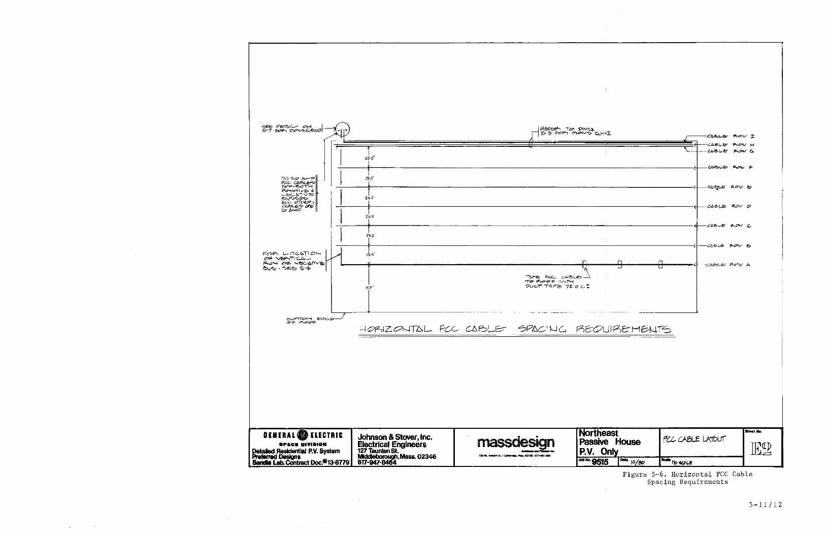
~ o&m..L-- "' .... 1b-7 """"" 17""""'[..'%0 - +
, I "1",, t I ("'l "''''' AHP t---
2M' ~U U>IO~
t ';::pp--, l!>oIH P~I'1"'IV& 4 i I t-..: e;.G., ~ -, v -e-. F?U_~ ! Z~·~ ilL-I.- 01l-IE?->
f ~~ /;?f!j 10 />...,0
I 1f;,,~
f , I i 2;.:3
I f. f"OF'-> l-ac:.!>.TIO'''-I H ",.' C* VI':lP->T'1 ~L- . ""U",-, <'>1'- Neut>11Ve,f-' r:>u ... - '?"'~ 1:;-4-
57"
e.~ON ~G.tE?"---.I (!:P~ P"'l<?G"'~
H OfZ,1 ZONTb L Pee
GENERAL. ELECTRIC Johnson & Stover, Inc. .,..0. DIYI.,DH Electrical Engineers
Detaled ResIdentIal P.V. System 127 Taunton St. PrefBmld~s MIddIeborough,Mass. 02346 SandIa Lab. COntract Doc.#13-8779 617-947-8464
~~~ To 1>\VCl,. 1'>- 5 ~.""., p"""V,,," u,H 4 J: CO~L-e.- 'P,O\V .~
U.61- eo- pt,O'\V ~ '\ ao6L-~ ,",oW G.
aobL-& '"""" F-
~~ fl,O\V t;
C-6e>1.-f,: ~O\v t;>
, "'617'-'" ".,,,,,v G-
C6~U:::: p.,O\V b
n n n CAe:-L.,.,~ J2,P\V A
Tt.P'& ~"- cA"=>L-E:> ~ w w
...,...~ fZ-,~cP"F ,-VITH 17u~, '''PI:o 7Z"O. c- t
C/::,5L8- "'SPh.CI f..J G PSE7QU I PJE:-H Bh1 is
IhHtNo. .~rtheast massdesign fU CAelf LATour Passive House ]{<tp P.V. Only .......... "--... 1.Mt......"St./~ ..... I2t./f1' .... loOII'
Job No-9515 IDolo 10/eo -t'o~
Figure 5-6. Horizontal FCC Cable Spacing Requirements
:..l.c:1
5-11/12
N-TbF'-, cou,--,,,,,C-TI C7J-!,,= '"~ "'''',....,PLEoTEoo ,= F-cc.-C6.oLe> p-,,,,,,V:r. ~H ~""V _l!> PO-s.,..,.,VE':; l..6-~
r- F'oL17 ~fZ-, T.". 17CHe.H"';:>LD ..... "=*!C"-VN ~ '~c>LL,~c... OUHFty--I"!"-I'-:'\-I'i'->P'V
u> P.;U:. f'.Q\v H_ ~1 1d<" f'JepP WC-<r<7l, [11,roe> Ii--lc..HE:1? lIVOll...b~[..e, "'''''"" I-IlI'l-n--lc... ,- I7UHH)/ ~H'J...jGL!bS
Ul?;(.e ~v ll. ~.~ .. a.L.; oJ--
~hf?Ll:, '" 0Y c.. r;P o h5=" ~----~--~- -~---------- -=
t.. 1-,0" 4>" ~N-rl-I ~,L.,H~~
<SH' '-l-wl..-b ...,,,,,y "" c..HTI-I I", .. ,v
1/ -
I-0
,-,b,1-- rl"'L-b ~ 1&,15' ~~TH p-.""v
r •
t ~ ~,
GENERAL. ELECTRIC Johnson & Stover, Inc. massciesig- --... ao. IIIYI.ION Electrical Engineers h " i i
Detailed Residential P.V. System 127 Taooton st. ~","""'I~
PrefernMI ~8 MlddIIIborough. Maaa. 02346 ,38 Mt. JWbI<m St.' c-_ ..... 021381 1J17-411.ol11!1
SaIdIa Lab. COntract Doc.#13-8179 617-947-8464
J-r«"p ,,"p ""1" E:o'c.o-m-.
~'H-GL& """"y
1&,tP(P'
1~,5~' 1(0.5' lIP,'"
" 1&$1,'
tfrrC7H E;oc..B' ""'" """""'10
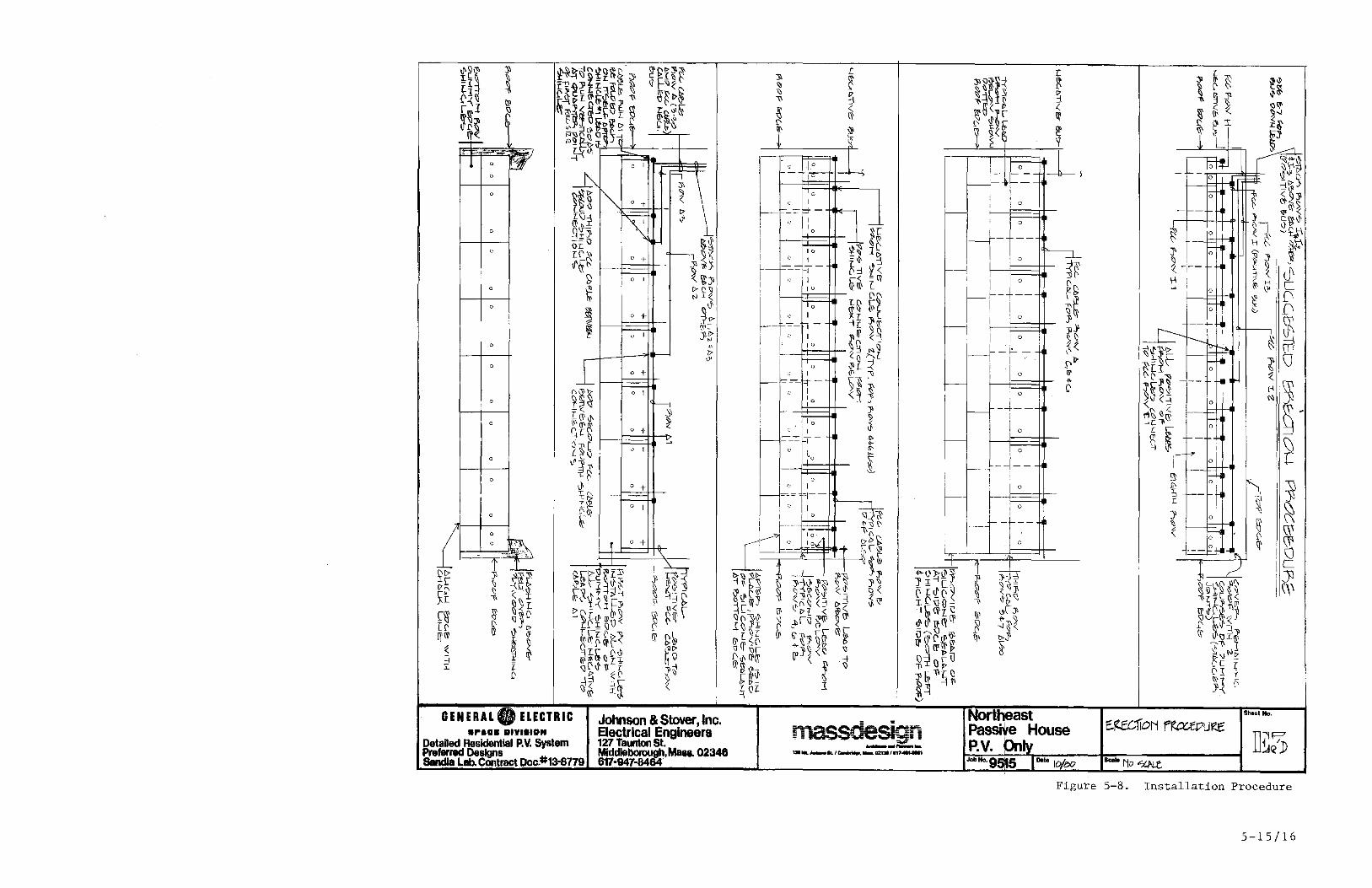
_tHo, I~rtheast PaSSive House -rof Ro~ ~IL-
TI~!j) P.V. pnly Job Ho'9515 I DII. 10/80 -No~
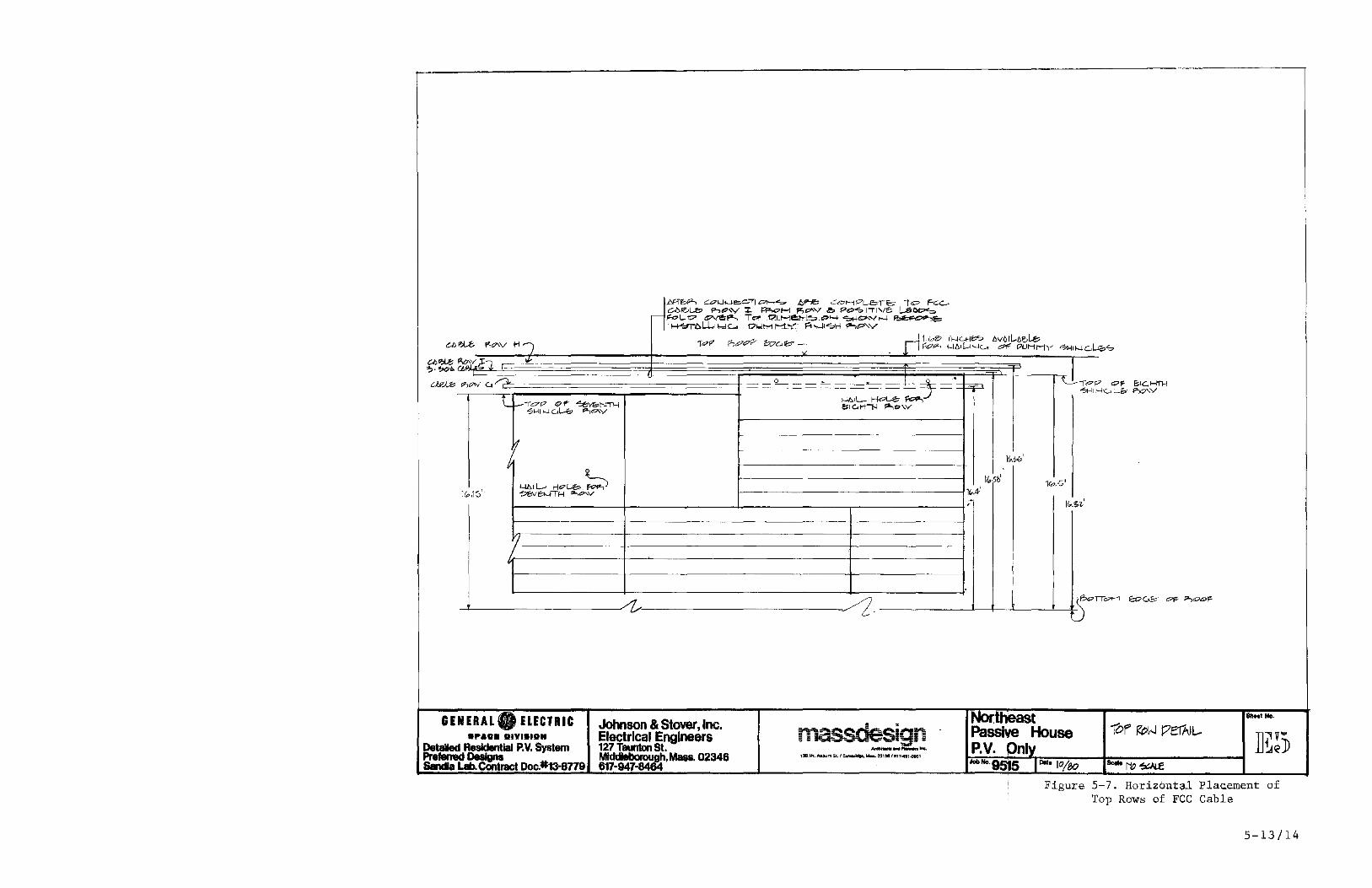
Figure 5-7. Horizbntal Plac.ement of Top Rows of FCC Cable
5-13/14
lI>\lijl 11 :t[~ ~ -I fl~ r-\l w
\l
~~~ ~ 11'~ ~ - . ,.::.~.-- . -1 D r:ff
D
0
D
0
i D
0
0
D
D
0
D
0
0
l 0
-~ I a -
~t Ir D-(' ~ -{ ~
~ -h ~ ~\\:r
[~ (j' ~ -< I qWC'
[l;- I' J '" [fll' \\' 11' ijI
~ ~ ~ =1 i: l
C'
GENERAL. ELECTRIC .,..oa IIIYlalllN
DetaDed Residential P. V. System Prefemld Designs SandIa Leb. COntract Doc,#13-8779
o + T
\
Johnson & stover ,Inc. Electrical Engineers 127 Taunton St. Middleborough, Ma ... 02346 617·947-8464
o
;'n.~""'''''' .. g'~r: .. - -- -.. ~ ~ D ~ ~ ..................... 13I_ ....... ""~ .... atal/ .. ,.......,
i---
o
I 0
_r---...+---I i
o
I 0
I ---1- '--o
o
---~--
i 0
i--- -!
o
I 0
o
Northeast PassiVe House P.v. bnly
Sheel No.
-No~
Figure 5-8. Installation Procedure
5-15/16
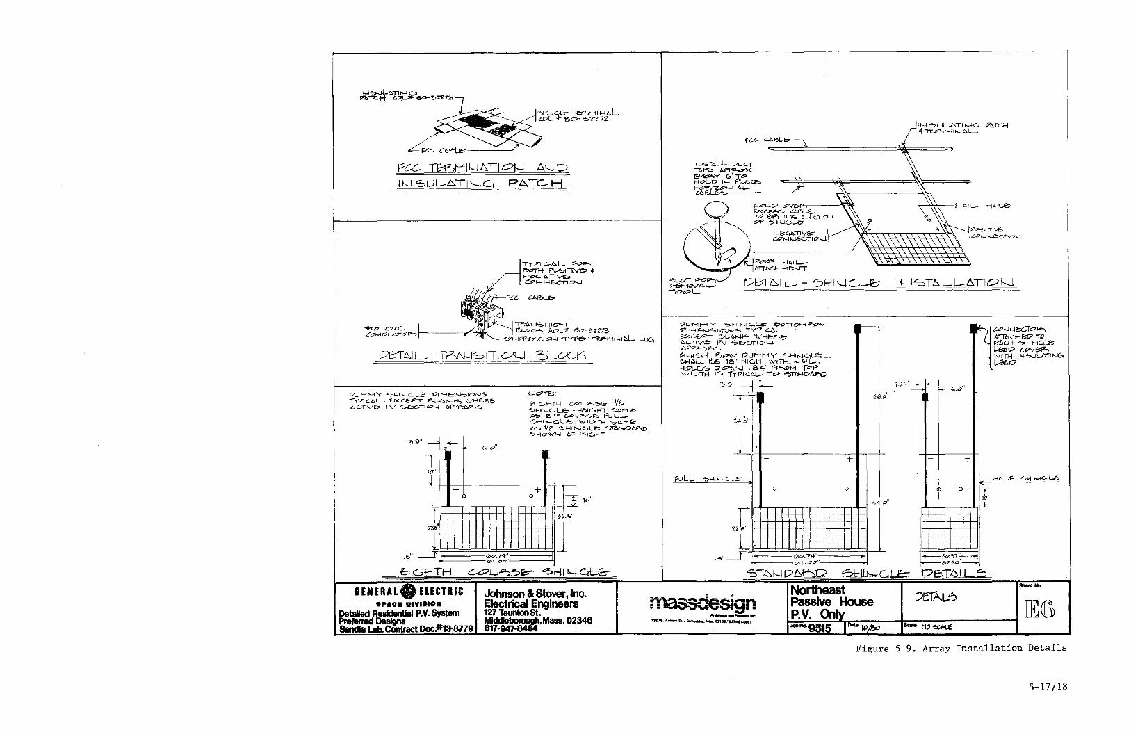
P4TC-H
1""-(171 C::-Q.L.,. F~
~ P<>?L11~4 1'---I-~b.T!V& Cd/t-l~'E=C'n~
.,..,.,/> '-'S rn oN ~""""' Ac:>LJ> 80- 3Z27S
r7Ut-11--1 Y "3>1-41 Nc....~ ~QTT"OI'--t ~V. 171 N ct-}c; I O.r-J."S. iYPI <::...OL. .
COH~ ""-' ,YPe" -'-"""1'11 ,,-,cl.- l..JJc" 6l<Gb?T e>t-A,,-,"'" \V,"e,P-,& l:>"-'"T1Ve- F'V '?e;.c.-TI <7'-'
De:-TLI L- ~I-ISITI OLi
?UHr--IY '"?1-I1t-.Jc....L....8 OIr-1~~IO'~S IYPIC-lO>'- ~Ch"""" ~ .... ,..., \VH<>?,b bC-nV(!? Pv "S>6C..-T"1 (';;.;)"'-1 b'P'Pe:;,C:.r.J-:,S
'-'<""fE>: ~lc..HTl---I CL:7U~~& Vz... ?~II-I'_ .. d_E;:: - Hbl61-tr ~r--fTC::; b-;, e,"TH u:::>u~ ..... E:; ~UL-L~HI~c::..L-E=; 'VIOi"H "":;>D.ME:; 6"'::;;. 1/2 ~1-l1 r-..Jc:....Le ?~N-D6F,D ?f.+o'V ...... 1 b'T" F'-,161-4T'
&IGJ:-lTH.
GENERAL. ELECTRIC ... AO. IIIYI.IO"
Detded Realdentlal P.V. System
==~~ract Doc.#13-8779
Johnson & Stover, Inc. 8ectrical Engineers 127 Taunton st. Middleborough. Mass. 02346 617-947-846'4
bPP8b""'" ' 1'<1_W?H p.,,,,, ... V OUr-tI"-1Y S,"I"-IC,t-ec __ ~~L-L P.:6 Ie" HIc:.H \VITH_ />..It.II-.l-IoL.~ OO\v .... . 84" 1"1"->"' ...... ToP 'Vi o-rH ''''' 1YPIU>!.-- ,.'" ~"""D~
?,.' ~ fo-
1. II~ :;4.0·
~r'~-----------------~'---+
o o
1~++r:++Q++=l::::r:+=l::t::r164.0' 22f 1 L'H, -++-++++-+++-H-+-+-Hl
,SOl I ';'0,74" I'------(p 1, ",,"'--------+1
massdesian ............ 2: ...
'.MI.AuDumSt./~'''''',021.!lIn.'''1
Northeast Passive House P.V. Only
ell I
Figure 5-9. Array Installation Details
5-17/18

The negative leads from the first active row of shingles are connected
to a single run of the triple layered negative FCC bus cable as indicated in the
second step shown on Figure 5-8. The positive leads from the first shingle row
are connected to FCC cable row B as shown in step three of Figure 5-8. The
positive and negative shingle leads are connected to the horizontal FCC cable
rows after nailing the shingles in place. All electrical connections and FCC
cable terminations are covered with a two-piece insulating patch, detailed 1n
Figure 5-9. The glass portions of the shingles are secured by an adhesive on
the back surface of the module to prevent module lifting during wind conditions.
Subsequent rows of shingles are attached in a similar manner. Figure
5-10 shows typical array connections on the roof. The positive leads of the
eighth active course of shingles terminate in a shingle run of the triple
layered positive busbar identical to the negative busbar connections. The
positive and negative buses are dressed through the roof to an AMP supplied
transition block shown in Figure 5-9. This block provides the transition from
FCC cable to the conventional cable. The remaining portion of the roof above
the eighth course is then covered with two courses of dummy shingles. Figure
5-11 shows additional details at the edges of the installation.
At the completion of shingle installation, gable edge strips are
applied to provide a weather-tight seal. The FCC electrical interconnection
system has been successfully installed at the Northeast and Southwest
Residential Experiment Stations with the GE Block IV-A shingle module.
5-19

Power Conversion Subsystem (PSC)
The power conversion subsystem, with the associated cabling ana
switchgear, provides the interface between the residential roof photovoltaic
array and the normal residential utility service and loads. Functionally, it
must convert the available array dc power to a usable and acceptable ac form. A
line commutated inverter manufactured by the Gemini Corporation and marketed by
Windworks, Inc., of Mukwonago, Wisconsin, is available in the 4 kVA range and
therefore selected for this application. It can be supplied according to the
sp~cification included as Appendix A to meet the preferred control options. The
pes is packaged in three units: the inverter, dc filter and transformer, along
with the control circuitry. Standard controls, filters and isolation
transformer options are provided by Gemini to encompass the requirements
specified for the residential design. Procurement of the basic inverter bridge,
desired controls, filter, and transformer from a single source is recommended to
assure compatible matching of PCS components.
Subsystem Requirements
The dc to ac conversion must be accomplished in a manner consistent
with residential electric practice. The conversion techniques should accommodate
the large range of solar array electrical parameter variations and residential
load and utility line voltage variations. The interface must provide safe
interconnections under all operational and failure modes and must provide
feedback of any excess array power to the utility. Equipment selection should
use proven technology to the extent available.
The requirements for converting the variable dc power and voltage of a
5-20
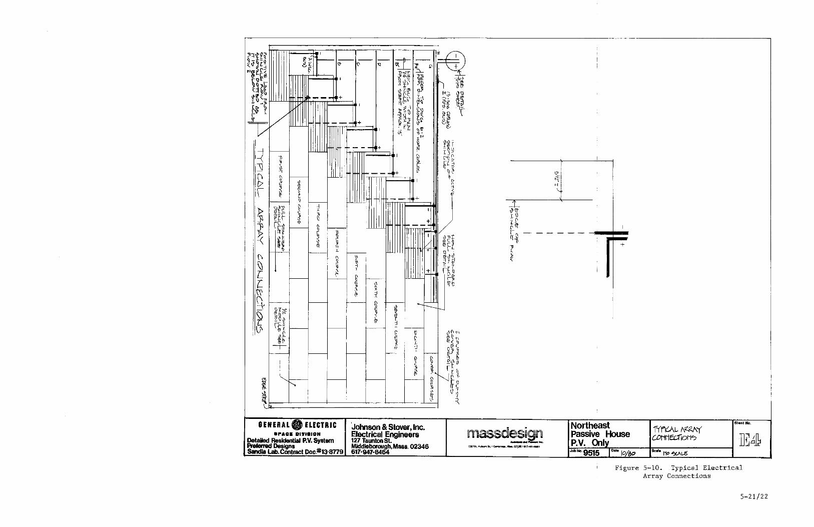
--- + Ihmnm::::::::::=~ I
GENERAL. ELECTRIC .PADS DIYI.IDH
Detailed Residential P.V. System Pre_AId Designs &ntIa lab. Contract Doc,#1:}-8779
!---- +
'Johnson & Stover, Inc. Electrical Engineers 127 Taunton St. Middleborough, Mass, 02346 617-947-8464
+
---------:==
mas.sdesian ........... ~ ... c ..
138Mt.AubllmSt.I~,""'"'-IJ2'9I/.'7"'".cJ8&1
+
Northeast Passive House P.V. Only Jobl<o'9515 Oat, 10/$0
Sheet No.
Se." No '5U\t..C
Figure 5-10. Typical Electrical Array Connections
5-21/22
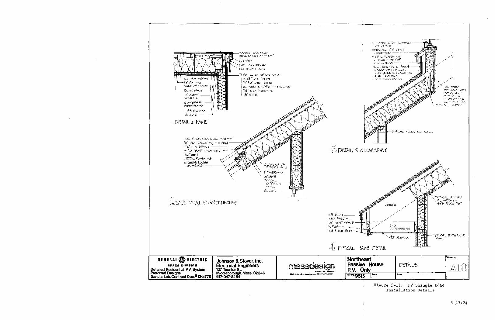
~~~~~~~~!i!i!!~~1FiIi""iii!t-- 'lAST! C- FLA'SHING>-RUNS uNDER PV. AR~Y
i"'''' ,RIM 1,,0 KAK=ecARD ,",,8 RA>(E F'ecei'<
f*f$~~~~~~~~~~~'-_IYf'IGAL 2XTE'f<IOR ",YALe 0 i EXTE;R 10" ""iN 1'S,rt ; Y2""'l:f 5rl~ATl-IING>
LLEARSTORY AWNING> ---~"'lLlL ININ.t7°W'O
SPECIA,- , 'h" veNT ASSEMBlY - -
.VlErA!.. "'lASHING i\WUED ,AFTER Pv ARRA'{-
! :2)(4 ""IUDS wiR-11 "16ERGLA'SS ~y::~C XA"v'\ :ZEn_AcES "2,..x:c ,=y2''<{ ,occ" A,? =<~."'5 ::'-'Ro..1::: ...... -:-0
I W' R,-& IrlE'-R',Vi-';,( 'h"GWf3,
~E, ,0iOTCVC_TAIC- ARRAY-/Z" PlY :)1'00< \tv "IS=~LT--~'" il/'2.iI Ai,'< SPACE -'------___7'
1;..," ...... '.'."I-r.e:,tvl.p .VIA"':;:'(N]j;S
COCl<E8N ------_~4.t
.' IET,"~ FL'lSHI NG --.;;;7';'T"~~W~ GRe::NHOLl5&
6L.,,",~IN6 -----'v~~~DLm~ '2 LAYER'S R-Il r:16:;',~~J\ .. :<~
\.. I"THE'RMAX
k"GIN3 -:-~-PIG_
r== (/) OEl,AJL e CLeAf(")IO\z'Y
0 .. _J:>"".~r.::;;:-:'" V:/ .. c '2- 2::< C -=:A7e=<.
EXIERIOR -~[jIK::-'!I:ilt
GENERAL ELECTRIC .,.AG. DIYI.ION
Detailed Residential P. V. System Preferred Designs Sandia Lab. Contract Doc.:II:13-8779
c,! .-..,::;(? -'-1./-·-..... ---
Johnson & Stover, Inc. Electrical Engineers 127 Taunton St. Middleborough,Mass.02346 617-947-8464
I)(S -rRi, ... 1-__ ~ i)(IO FASCiA---J:loI j'/2" veNT SPACE
0ci<eeN ~---J::I.
tl-.iP~==<~:===~====~t:?;~:LlY"CA_ =,)(-",,<,0'<. WAL-_
,;j1-rr'flt:AL EAVe t7ciAIL
= • r.;~~~~S--~§""ll~ • ;; __ ........... ...,,' "_iii"
Ardde!:IIIId ~ lno:.
1:18 Mt. Aubum SI. I C;omt.ri<:t;IJ. Maa. 02138/61'-C~1.()96'
Northeast Passive House P.V.
OefAlL<?
Figure 5-11. PV Shingle Edge Installation Details
5-23/24

photovoltaic array to the utility residential fixed ac voltage low impedance
interface can be reliably and economically met by solid state electronic
inverter device, acting as a current source to transfer power. Although either
self- or line-commutated inverters can meet the requirements, the latter is
selected for this application. The line-commutated inverter, however, as
applied to this residential system has the inherent disadvantages of poor power
factor and high harmonics. On the other hand, it has a large technology
application base and has been applied and tested ln PV app.ications by several
installers.
Subsystem Sizing
Array IV characteristics are shown in Figure 3-3 at SOC conditions.
The characteristics indicate a maximum power rating of 4.1 kW and rated voltage
of 132.8 Vdc at NOCT. The array maximum power point and associated voltage
exhibits a dynamic variation with insolation, temperature and wind variations.
The array maXlmum power point and voltage is examined on an hourly basis for
Boston based on TMY weather data. Figures 5-12 and 5-13 illustrate the
distribution of the maximum power and maximum power voltage, respectively, as a
function of the array annual energy for Boston. These curves r~present the
array/PCS interface requirements.
Note that the array open circuit voltage under start-up conditions is
significantly higher than the maximum power point operating range limit of 188
Vdc. The initial high open circuit voltages during start-up has been a problem
for the prototype units under test at the Residential Experimenatal Station.
5-25
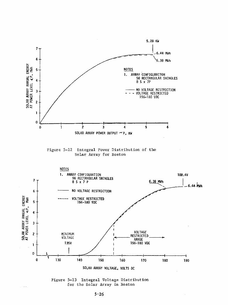
>-<.!l '" .<:: ...... '" z:: "-' -' c..
~" z: z -' CCLLl
:> >- LLI cc-' '" "'''' <LLI
"'~ cc c.. -' 01-V> "'"
7
6
>-<.!l:<:
"'''' 5 W 0;: Z "-' -' c.. ~v 4 z z -' cc LLI
> >- LLI 3 ;:1!-'
'" '" "",W
'" '" 0 2 <0. --' 01-(1')<
0
5.28 KW
7 I _6.44 MWh - --- -\.38 MWh 6
5 NOTES l. ARRAV CONFIGURAITON
4 56 RECTANGULAR SHINGLES 8 S x 7P
-- NO VOLTAGE RESTRICTION 3 VOLTAGE RESTRICTED 156-180 VDe
2
O~ ____ ~ ____ -+ ______ +-____ -r ____ ~ ____ ~
o
0
2 3 4 5
SOLAR ARRAY POI~ER OUTPUT"'" P, KW
Figure 5~12 Integral Power Distribution of the Solar Array for Boston
NOTES 1. ARRAY CONFIGURATION
6
188.4V 56 RECTANGULAR SHINGLES 8 S x 7 P 6.38 ~h. I l...
'._--'"~ - 6. 44-flWh NO VOLTAGE RESTRICTION
VOLTAGE RESTRICTED 156-180 VDC
VOLTAGE MINIMUM VOLTAGE .-4:-__ RESTRI CTEO ----i.~
RANGE 135V 156-180 VDC
150 160 170
SOLAR ARRAY VOLTAGE, VOLTS DC
Figure 5-13 Integral Voltage Distribution for the Solar Array in Boston
5-26
180 190

The annual distribution curves for maximum power and voltage in
Boston, Figures 5-12 and 5-13, can also be used for subsystem sizing
specification and operating voltage specification. The power distribution curve
of Figure 5-12 indicates that 6.30 MWh of annual energy is generated at a 4 kW
array rated level or below. The figure also shows a system peak power output of
5.28 kW. Only 2.2% additional energy is generated above the 4 kW power level.
This implies that selecting a standard size 4 kW output rated pes, captures
nearly all of the available energy. (A 4 kW output rated inverter, assuming an
average inverter efficiency of 87%, would accept input power levels up to 4.6
kW). The input power duration curve, Figure 5-14, indicates only 300 hours of
the total annual operation at a power level of 4 kW or greate~. This further
substantiates the selected inverter size.
Figure 5-13 shows a wide swing of the system maX1mum power point
voltage from 136 to 189 Vdc. The voltage can be expressed around the mid-point
of the range as 162 ~ 17% V. Accommodating the wide input voltage range usually
results in poorer efficiency, poorer power factor and higher harmonics in the
pes design. Since the curve 1S "s" shaped with relatively flat ends, the
maximum power voltage range can be limited with minimal loss of energy. Hourly
simUlation analyses, with excursion limits placed upon the maximum power voltage
of 168 ~ 7% V, are shown as the dotted curve 1n Figure 5-13. The annual energy
collection with these limits is 99.1% of the unrestricted case. Thus, a voltage
limit of 168 ~ 7% Vdc input to the inverter is selected to enhance inverter
performance with minimal annual energy collection losses.
These summary requirements have been analyzed for this Northeast
residential design and detailed in a specification as referenced in Appendix A.
Technical characteristics for the pes are summarized in Table 5-2.
5-27
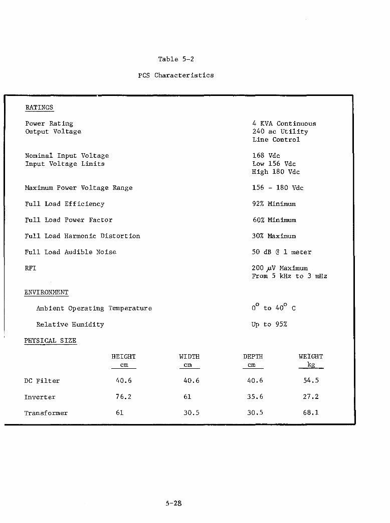
Table 5-2
PCS Characteristics
RATINGS
Power Rating Output Voltage
Nominal Input Voltage Input Voltage Limits
Maximum Power Voltage
Full Load Efficiency
Range
Full Load Power Factor
Full Load Harmonic Distortion
Full Load Audible Noise
RFI
ENVIRONMENT
Ambient Operating Temperature
Relative Humidity
PHYSICAL SIZE
HEIGHT cm
DC Filter 40.6
Inverter 76.2
Transformer 61
WIDTH cm
40.6
61
30.5
5-28
4 KVA Continuous 240 ac Utility Line Control
168 Vdc Low 156 Vdc High 180 Vdc
156 - 180 Vdc
92% Minimum
60% Minimum
30% Maximum
50 dB @ 1 meter
200 pV Maximum From 5 kHz to 3 mHz
Up to 95%
DEPTH cm
40.6
35.6
30.5
WEIGHT kg
54.5
27.2
68.1

6
_5.28 KW 5
4
'" '" ~ " .
0.. 3 t
'" UJ 3: 0 0..
2
o o 500
'"
1000 1500
HOURS AT POWER > P
NOTES 1. ARRAY CONFIGURATION
56 RECTANGULAR SHINGLES 8 S x 7 P
2. POWER IN EXCESS OF TARE LOSS
-- NO VOLTAGE RESTRICTION
2000
VOLTAGE RESTRICTED 156-180 vac
3195 HOURS
2500 3000
Figure 5-14 Power Duration for PV Array for Boston
PCS Specification
The system schematic diagram, Figure 5-15, establishes the
interconnection of the PCS to its interfaces. The PCS consists of an inverter
with control circuits, a dc input filter and transformer.
Inverter Specification -- The major item within the inverter is the
conversion circuit. The inverter conversion circuit consists of a SCR thyristor
bridge with SCR phase angle firing control electronics and initial adjustments
for voltage and current limit settings. Commutation of the SCR's is accomplished
by the reversal of ac line voltage as seen by the bridge circuit through the
transformer, hence, line commutated. The phase angle firing control point is'
dynamically adjusted within limits to transfer the maximum available array
5-29
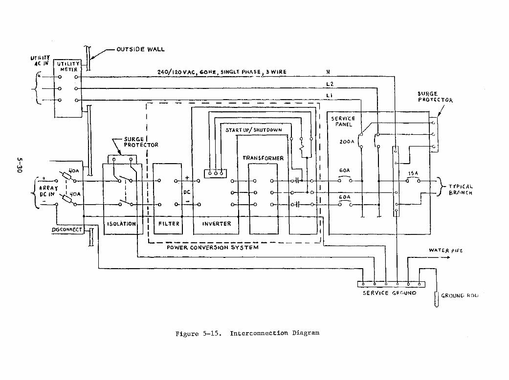
I.J1 I
W o
ur ~
{ -
11'( IN UTILITY I-
METfA
--!-o l-
'iOA
.!.-o I RI.' A,. I
I \fOA Ie 11"1 { -=--DISCONHECT
~OlJTSIDE WALl.
240/12.0 VAC, ~OH1!. $IH<OLE PHI\S~! ~ WIRE
I 1 I I
I START UP/ SHUTDOWN I
\" SURGE I I PROTEYOR ::- I
I I 9 I I TRANHORMER 1 1 \ I
I I ~ "- I + I I~
I ". I
0-1
I I DC l-I I 1 ~ - ~ n - .. - I II
I I
ISOLATION I FILTER INVERTER I I I I L _____________________ I
POWER CONVERSION SYSTE'M
Figure 5-15. Interconnection Diagram
» Ll
LI
SERvl'CE
PANEL V ZOOA ( (
GOA
-0--
GOA ;::--
.
I I I>
SUf/GE PROT[C DR
I-
,:IJ -
e
,
ISA :---
r '} TI'P,(AL
~R/'N(~ f-
WI p. P JJ"f -I
01
SE~I/ICE GRGUNO
I ROUNG ROL;

power. The initial adjustments provide for three set points: dc turn-on
voltage, IV load line slope, and current limit. These adjustments are described
below.
1. DC turn-on voltage -- This adjustment determines voltage input below which no power inversion takes place. This assures that the array source will have useful output before any loading takes place. Adjustment of this voltage is dependent upon the system characteristics and for this design it is set for 120 Vdc nominal.
2. Current limit -- This adjustment determines the maximum dc current that will be converted to ac and is essential for protection of both the power source and the inverter circuitry. Excessive current can be harmful to the components of the inverter or to the wiring or distribution equipment. Current limiting is accomplished by sensing the dc current and adjusting the switching action to avoid any excessive current.
3. IV Load Line Slope This adjustment determines the pattern of current rise that occurs as the voltage increases beyond turn-on voltage as described above. As the voltage increases, more and more current 1S converted to ac up to the point where current limiting action occurs. The amount of voltage increase from the turn-on voltage to the value at the current limit point is the current slope voltage.
Suitable fusing is also included on the dc input to the bridge circuit and the
ac output from the bridge circuit.
Start-up/Shutdown The control circuitry for daily operation is
shown in Figure 5-16. The inverter will operate in its normal mode when the
main on/off switch, Sl, 1S closed. The operation is illustrated by following
the sequence of circled numbers around the diagram. In the morn1ng when the sun
rises, the array dc voltage rises exponentially. It should be noted that the
array open circuit voltage 1S significantly higher than the maximum power
tracking range. A sensitive relay or solid state logic circuit, C, closes the
circuit for the ac input contractor B. AC line voltage, Ll and L2, will then
operate the dc input contractor, A, permitting the inverter to transfer power.
If either L1 or L2 should fail, contractor A opens, thus shutting the inverter
5-31
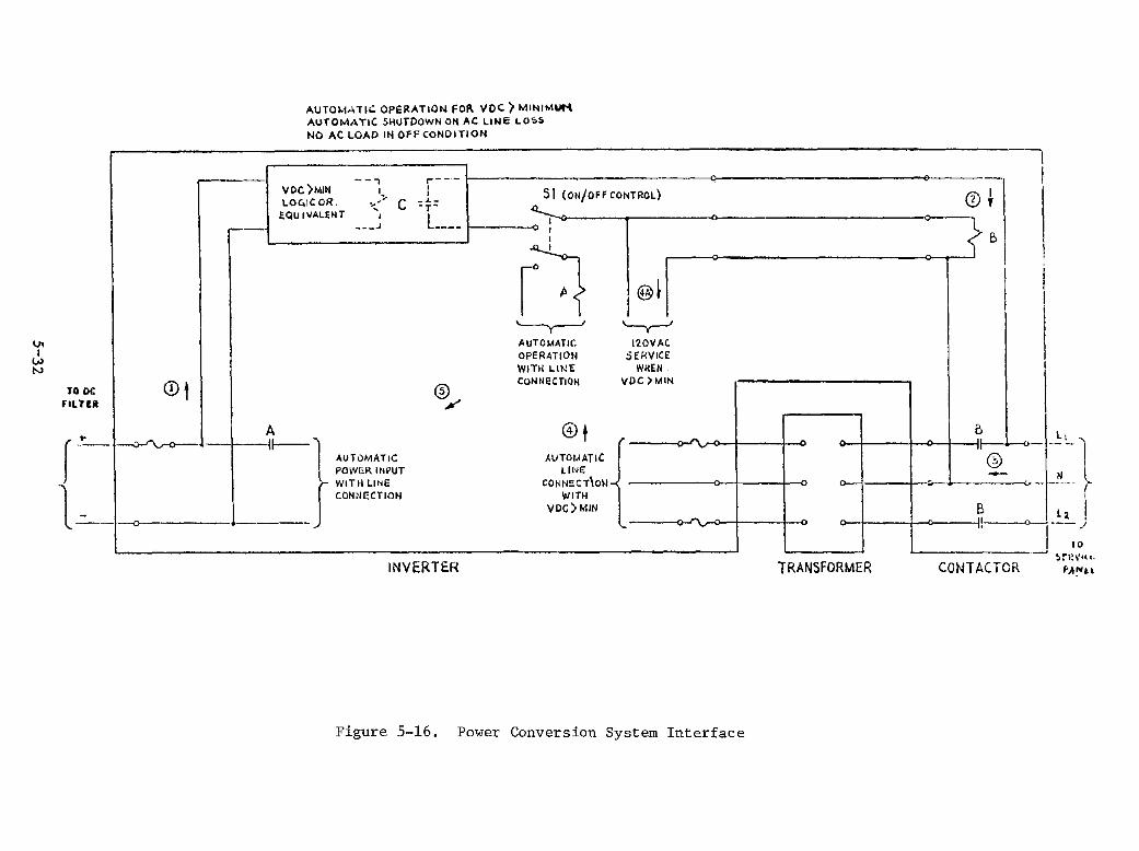
vI
V> N
TO OC FILTCII
0t
r-~-I~
AUTOt.1ATIC OPERATION FOR voe; > MINIMUM AUTOMATIC SHUTDOWH ali AC LINE LO;,5 NO AC LOAD IN Off CONDITION
VOC)MIN LO"iC OR.
EQu IVALENT
--, I"
~,'" I
___ J
:---1 51 (ON/Off CONTROL) 0 • f2\ I C _J._ \V ,
-T-I .... ---- I 0
I I I
r~ {B
'---1 -0--0 -----co>----<r--'j .
A -I----U--- "\
AUTOMATIC
® ",
~ AUTOMATIC OPERATION WITH LII>!E CONNECTiOH
@t
I @~ '---y---'
120VAC SERVICE W~EN
VDe )MIN
r o-"'v--o I I 0
I
1--1-;>- ~--POWER INPUT
~ WITH liNe CONNECTION
AUTOMATIC LINE
CONNECT\ON -<
WITH VDe) MIN
~ ~ :~I~~l Q 1 1
o-j B La I '-----0---.;, ~ -- /
o 1 1 a I. I 10
INVERTE.R -----:-::~.--.I ~r?\.lu_
TRANSFORMER CONTACTOR fA!,,"
Figure 5-16. Power Conversion System Interface

down. Auxiliary logic and timing controls verify a net power output on start-
up. For no net power output, the inverter shuts down again for a preset short
period to avoid rapid cycling. When the sun sets, the inverter shuts down for
the night due to net power less than zero. This evening shutdown and opening of
the ac line contractor eliminates night-time no load losses on the transformer.
Maximum Power Control -- The operation of the maximum power tracking
controller is based upon the photovoltaic power-voltage characteristic shown In
Figure 5-17. A simplified block diagram for this tracking controller is' shown
in Figure 5-18. The basic elements include:
1. A wattmeter circuit that continuously measures the power level and provides a signal output proportional to actual power.
2. Two sample and hold circuits, controlled by a timer, that alternately sample the wattmeter signal output and hold it for comparison with the next sample.
3. A comparator that works in combination with a logic circuit to determine if a given sample represents a power level that is greater or smaller than the previous sample.
4. A flip-flop circuit that changes state whenever a new sample is smaller than the preceding one, but remains in the same state if a new sample is larger than the preceding one, thus representing an increase in power level.
5. An integrator circuit that provides a constantly changing output, whose direction of change is increasing for one state of the flip-flop and decreasing for the other state of the flip-flop.
5-33
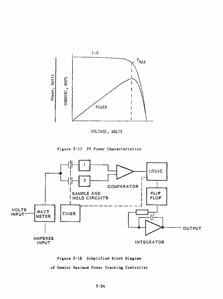
VOLTS INPUT
WATT METER
v> +-' +-'
'" 3 . S-<lJ 3 0
c...
AMPERES
I-V
VI 0.. -<: . f-Z w "" 0:: ~ U
VOLTAGE, VOLTS
Figure 5-17 PV Power Characteristics
I I I ~---I LOGIC
I 2 1-'---,----' I COMPARATOR :
SAMPLE AND I I HOLD CIRCUITS I
FLIP FLOP
81 ___________ J
TIMER Fr:2 ~--- OUTPUT
INPUT INTEGRATOR
Figure 5-18 Simplified Block Diagram
of Gemini Maximum Power Tracking Controller
5-34

The output of the integrator is the signal which controls the input
voltage level to the Gemini. It has limits which are set so that it does not
attempt to control voltage beyond the tracking limit set-points. The integrator
constantly changes its output in a direction determined by the state of the
flip-flop. If, for example, the flip-flop 1S forced to remain in a state that
causes a constantly increasing output of the integrator, the Gemini will sweep
through its voltage range starting at a low level and increasing to maximum as
determined by its preset limit. If the state of the flip-flop is changed and
forced to remain in the opposite condition, the integrator signals the Gemini to
sweep down the curve toward zero.
In automatic operation, the flip-flop is not held in any particular
state, but is allowed to change as determined by the interpretation of
successive samples. The sample rate 1S adjusted so that many samples are taken
in the time it would take the Gemini to make a complete sweep from minimum to
maximum or from maximum to minimum.
If the Gemini starts at zero voltage and 1S moving in a direction
toward maximum voltage, as each sample is taken, the logic circuit and the
comparator compare it to the preceding one. On the short-circuit current side
of the maximum power point as the voltage increases, each sample of power is
larger than the one before it, and the flip-flop does not react. The voltage,
therefore, continues to rise. Eventually the voltage reaches the value
corresponding to maximum power point and passes through it. When this happens,
the next sample of power indicates to the logic circuit and the comparator that
the power has decreased from the preceding sample, and the flip-flop changes
state. This causes the voltage to stop rising, reverse movement to a downward
direction, and return toward the maximum power point.
5-35
From this time on, the voltage cycles back and forth around the
maximum power point, reversing direction each time it moves far enough to
indicate a decrease 1n power. If the source characteristics or output changes,
an automatic readjustment stores the Gemini voltage control to the new optimum
point. To provide minimum voltage swings in the area of maximum power and to
allow optimum stability, the rate of voltage change as well as the time between
samples, is adjustable.
De Input Filter and Transformer Specifications -- The remaining two
packages of the pes are the dc input filter and the transformer. The dc filter
inductor serves the function of maintaining current flow through the conduction
portion of each thyristor commutation cycle. This reduces the current harmonics
to levels acceptable for use or further filtering if required.
provides the filter package to match the inverter and power ratings.
Windworks
The third package of the pes is the transformer. The transformer
serves the dual function of providing isolation of dc array output and the ac
line and matching of the ac line voltage to the dc voltage for proper
commutation. Isolation of the sources is a mandatory circuit requirement when a
grounded dc bus is used in the array design. The negative bus is ground'ed ~in
this design, thus requiring an isolation transformer.
The transformer will be rated higher than the inverter bridge and pes
as a whole to accommodate the out of phase ac voltage and current. A nominal
rating of 5 kVA for the transformer 1S suitable for accommodating the
anticipated power factor of operation.
5-36
employ
PV Array Electrical Interface to Conventional
House System
The basic approach for design of the interface arrangements is to
conventional wiring runs and equipment in a manner to maximize safety in
accordance with the National Electric Code requirements. Since the PV system is
a self-generating source of electricity for the residence, it must be
interpreted as an electrical service and is treated in the same manner as the
utility service.
The array positive and negative FCC buses are brought down through the
roof approximately 2~.4 cm down from the peak between the rake and exterior wall
surface. The buses pass through a 2.5 cm raceway sleeve to the top of the
transition block (AMP, Incorporated Part No. 80-32273) and box enclosure.
Reference Figures 5-9 and 5-19 for transition block and roof rake details. The
transition block converts the FCC bus cables to #6 AWG positive and negative bus
conductors. These conductors pass through 2.5 cm PVC conduit and follow the ac
utility service entrance cable to the exterior PV array disconnect switch. The
PV service entrance is located at the same exterior wall as the utility service
as shown in Figure 5-19. This visually separates the residence from one having
only a normal overhead service and should alert emergency personnel that two
power systems are in use.
Since the equipment area is located at an exterior wall, the PV
disconnect could have been located inside the equipment room along with the
utility service disconnect. However, exterior disconnect capability is
preferable as it affords a visible break of the PV array supply. The disconnect
switch includes fuses for overcurrent protection required by code requirements
5-37
~
for electrical service devices. The PV array will generate a maximum of 110r. of
full load current, even if shorted.
The PV system schematic wiring diagram is shown in Figure 5-20. An
additional unfused disconnect is provided 1n the equipment room at the dc
service entrance location. This provides array isolation, and when used 1n
conjunction with the disconnect switch between the inverter and ac house
panelboard, allows safe maintenance on either the dc filter, inverter or
transformer. The positive leg of the dc system is surge suppressed with a
varistor connected to the array side of the interior disconnect switch. This
varistor provides surge protection of the array, even if the interior disconnect
switch 1S open. Beyond the indoor disconnect switch, all dc power is carried
through a raceway system to the inverter enclosure. Electrical connections
between the dc filter and inverter are conduit encased. Connections between the
transformer and inverter are through 3.8 cm Greenfield. All other power
connections from the inverter to the ac house panelboard are conduit encased.
The service pane I board is provided with residential type lightning arrestors to
provide output circuit protection to induced voltage surges.
An exposed copper house ground bus is located directly below the
service panelboard. This provides a visible and accessible means for
terminating all grounding conductors. The house ground bus is connected to the
incoming water service as prescribed by the National Electric Code. An
additional ground rod is provided should the water service ground be unsuitable.
5-38
I
I I !I
II I! J ,r-
GENERAL. ELECTRIC ."aa. DIYI.IDN
Detaied Residential P. V. System Prefemld DetiIgn& SandIa Lab. COntract Ooc.#13-8779
'I I
I
Johnson & Stover, Inc. Electrical Engineers 127 Taunton St. Middleborough. Man. 02346 617-941-8464
~ [;>e;r.bl L. ~L.Q\"'V
F"c:.-V <:.<l.1OL-= ~= 1"-1 t~·c.- Fi">C7M ,l>p.,"'>4y PUU-~
C7 '"[l>-,~N':>J T1 QJ,! 1'>"""-
PLbl'--l
Mbll'-l.rorN 1'2 1'
~1Ip., 0 ..... = 1!>f>T\ViCJ;>.J ~F .. ,yJc.e,,,,, -
s-y;>,1\P -:;uppop.,r-;:, 1'-1 6a.o""IA!>J-Je,lO,YJTH \.J.e.. Co. (TYP I CAW •
..._---:If:(o 6.,vv, p":;;;>~1 TIV& !:,o;....n:i1Uc...io~ pt...uS -IF"" ue.c.. ... -nve:- ~CU<ToP, ~ J~ 1 I' PVc.... Co""",,,ou IT"
theast PaSSive House P.V. On
.... tHo.
Figure 5-19. PV Interface Arrangement
5-39/40
[li-#Ce> ""Yc;'
I 1" pyc,
I
11 rl "'*"14 c.'Y0, <:.;"",.,&0--1 ',",";>UL.t> reo
c."""'u,,",o """,""-. "c.F">I~~ TO' H","W"",& C.~ND ~U-;'
bt:?UIf'HC::;NT ,H ~t>~e>Hel'-iJ..
@
t:T!f.- CD ,6 \vc., T"* £> 6,",VC::J C::><;>UI pr, C.1",¢UN-D
+
f-C:-+-<
PU?&7 -Z 1"''''' 1..-0' ,<be> t>H'F"~""', \!:"Ic> vo L..."1" t;>'''''C-c>N''-IEOCr '5\VITCl-j (~'" -'?f'» (P'f'-,O\/lDe. f7ADl..OO<)(40~ .u""~, p>e,,:e,,,,, T"" O\Vc.... &-9 F=~ e. .... U I pr-teNT
ourLBT- B~>< B"~, X Z" DP: 'Y!?c..P'-,f,"y C"'v~, \V1Tl-i VbF' I-;:'~ FoP", r'OSlllYli':> ["eO- P>""'''''r-t l..-!;.'(OUT"" ~ EihVI>"rIO .....
UO ....... Fw~P 2 f7ou:.- , <00 AI-fP~ ,240 y""c..;:r ,I7,?CO'UU6CT -z>,v 1 Tc.M (~A I)
"\",,'-.4 ~- -?'YII-+G'1-lG IUDUGT=h '4 ,'" ,\I X 110'1-/)<1(0" oblOF" JUF-ICT,c:>H, !!;>OI< W/HIH~O ~f"o i'-'ve:;....,..,..~ e-Nc..L05U~ 'Z4" \VX ""'0" H x 14" OE£? (1'1--""""'1"-> HC:>UH~)
"5 "",VI:> T""t><-l"':>F<OP-M6f<., '2-.' H '" 1Z"W x 11:-" i?r:C-?
... O"':-f~"""'O ~'" 6M~e , t.. Pc>I...!::"", :t~':>vOL...T Oi'?COiU l-.iter ?\VITGI-j (1-II!;t-Ill. 1)
1--10""HAL.... ?j~rl7~<-lCb cjPx:,UIT ~r<>~P-, P'A':-''''~P-,D L...1C.HTt--Il ..... c." ~~ '-i'ppL...co -;-0 uou""",e=- pt>NIfs'l--
P-\f. 'SY-vT8H OWE;- U~ Dll:::.c~aM
GEN ERAL. ELECTRIC Northeast Passive House P.V. Only
- .... .,.AG. IIIYI.'DN
Detailed Residential P.V. System Preferred Designs Sandia Lab. Contract Doc.#13-8779
Johnson & Stover, Inc. Electrical Engineers 127 TaunlonSt. Middieborough,Mass.02346 617-947-8464
n"l~~~~~"n~ ai~_;, _ ..................... 138 Me. AuIIunII!It. I ~ "--OZ"-/.,7 ..... ~'
pv, "JY":>-reM OHc L-1t1E. 1?1~
Figure 5-20. PV System Wiring Schematic
5-41/42

UL-Iabeled materials are used for all phases of the installation. All
equipment is labeled and a copy of the schematic diagram will be posted in the
equipment room. Appendix B lists the electrical system installation
specification.
Equipment Area Electrical Layout
The equipment area contains all the major equipment associated with
the power conditioning and distribution of the solar array power. This area is
located in the southwest corner of the basement level. There is no need for a
self-contained or enclosed equipment area.
Service entries to the equipment area from the outside disconnect
switch and utility service meter are via thru-wall nipples. Equipment placement
1S 1n accordance with the equipment area plan as shown in Figure 5-21. Wall
installed equipment is mounted on a 1.9 cm plywood backboard. This includes the
panel board disconnect switch, the house circuit breaker panel board and lightning
arrestors. The inverter and isolation transformer are floor mounted. A
tabulation of major equipment is listed in Table 5-3. Appendix B provides the
complete system installation specification.
5-43

Table 5-3 Major Electrical Equipment List
• Disconnect switch, fused, 2 pole, 60 Amp, 240 V, NEMA 3-R enclosure
• Varistor, GE Type V275LA40B
• Disconnect switch, non-fused, 2 pole, 60 Amp, 240 V, NEMA 1 enclosure
• Iron core swinging inductor, Gemini Corporation
• Inverter, 4 kVA, Gemini Corporation
• Isolation transformer, 5 kVA, Gemini Corporation
• Residence Circuit Breaker Panel board
• Varistors, GE Type TLP175
Lightning Protection
The lightning environment for the Boston area is shown in Table 5-4.
Due to the low isokeraunic level in the Northeast and the low probability of
residential building lightning strikes per year, nominal protection utilizing
surge arrestors will be installed on the positive array input terminal is
services with a GE Type V275LA40B varistor. The utility bus is surged suppressed
with GE Type TLP175 varistors. These varistor types provide inverter input and
output circuit protection due to high voltage surges.
5-44
,
l ~ r
0qUIPHE:::WT LbC-rt:;ND [f,~ TC> DWe::..,. I!oe> ~ t.DDITI D~(lk_IOE>i-JT1flc.Il.Tla'-D
CD ~"""c.o'-<'-I.e:;c..T -?w 1 Tc:.H
® VIl.f'-> I~Tr.>po-,
@ p'?C.=HN6-c...T ""'VlTc:.H
® -I "-IQI..JC.T"~F'--,
® i t-.> V e,p.,[eri'->
® , .... =L..f.>TI .... c.. TJ"->t.> No;,.J"'e.> r=o-, N ~
en V'1."CG?t--1N E%-T """VITvt-i
@ t-i<;:>~ GII'-<:.LJIT ~f'->1!'>fZ-., PC>NE>L.~c<>t. P-,D
® :....; c...r-n1JING ~T~
GENERAL. ELECTRIC .rAII. ItIYI.IIt"
Detailed ResIdential P.V. System Prefamlcl Detllgns SInIa Lab. COntract Doc.#13-8779
Johnson & Stover,lnc. Electrical Engineers 127 Tauntoo st. MIddleborough, Mesa. 02346 617-947-8464
o 1 2 " 4 ,
massw~sign ~"'''''''''k
13111t.''''*'"'lt.l~,~It'Z1.'1170411'''''
1~:House P.V. 'Only """No.9515 I ... • IO/eo
e.aulfi1t:1if ~Cl:>M f'LAH 4- eL..E.VAAON?
Figure 5-21. Equipment Room Layout
5-45/46
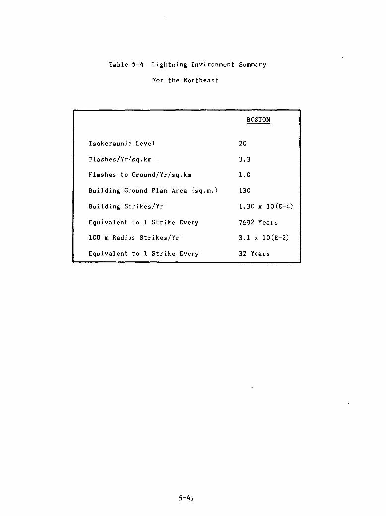
Table 5-4 Lightning Environment Summary
For the Northeast
Isokeraunic Level
Flashes/Yr/sq.km
Flashes to Ground/Yr/sq.km
Building Ground Plan Area (sq.m.)
Building Strikes/Yr
Equivalent to 1 Strike Every
100 m Radius Strikes/Yr
Equivalent to 1 Strike Every
5-47
BOSTON
20
3.3
1.0
130
1.30 x 10(E-4)
7692 Years
3.1 x 10(E-2)
32 Years

SECTION 6
SYSTEM DESIGN ALTERNATIVES
A logical extension to the present, highly energy conscious design is
a solar domestic hot water system. This system would further reduce the total
electrical load requirements on the house. This option was evaluated for a
Northeast residence in the side-by-side PV/Thermal design report, Reference 15.
In that design, approximately 8 sq.m. of thermal collectors reduced the hot
water demand by 651. in Boston. This results in an overall reduction of 221. in
the total electrical loads. The overall system economic viability and PV system
size remains unchanged with this option, and the total yearly energy bill of the
house is reduced. The amount of PV energy used directly in the house does
decrease as indicated in Figure 3-7. For this specific house design, however,
the roof area would have to be increased slightly or the PV array area would
have to be reduced to accommodate the solar thermal collector area.
Similar results would also be expected if a hot water recovery unit
was used to reduce the total electrical hot water requirements. This option was
evaluated in Reference 16. The net reduction in the hot water demand would not
be as significant as 1n the solar thermal hot water system, but no additional
ro~f area 1S required.
Since all potential options could not be addressed in each design, the
reader is directed to References 15 and 16 for more detailed discussions of
these design options.
6-1

SECTION 7
REFERENCES
1. "Final Report - Regional Conceptual Design and Analysis of Residential Photovoltaic Systems," SAND78-7039, General Electric Company, January 1979.
2. "Final Report Analysis and Design of Residential Load Centers," SAND80-7017, General Electric Company, October 1981.
3. Caskey, David, "Selected Residential Electric Rates and Rate Structures 1n the U.S.," July 1979, Sandia Laboratories, SAND79-2110, January 1980.
4. "The Design of a Photovoltaic System for a Southwest All-Electric Residence," SAND79-7056, General Electric Company, February 1980.
5. Personal Communication with R. Smiath, Sandia Laboratories, October 1979.
6. "Solar Energy Thermal Processes," J .A. Duffie and W.A. Beckman, Wiley 1974, Page 76.
7. "Residential Photovoltaic Module and Array Requirement Study," Report No.
8.
DOE/JPL-955149-79/1, Burt Hill Kosar Rittelmann Associates, June 1979.
Lee, Jr., "Future Residential and Commercial Demand in the Northeast," (Prepared for) Energy Research and Development Administration Under Contract No. E(30-1) 16, (Report No. BNL 50552.) Upton, New York: Brookhaven National Laboratory, March 1976.
9. Department of Energy, "Final Energy Efficiency Improvement Target," Federal Register, April and October 1978.
10. Balcomb, J.D., et aI, "Passive Solar DOE/CS-0127/2, January 1980.
11. "Typical Electrical Bills 1977," prepared Bureau of Power, U.S. Government 015-000-00364-2.
Design Handbook,"
by the Federal Power Printing Office,
Vol. 2,
Commission, Stock No.
12. "Photovoltaic System Sizing Analysis," G. Jones & E. Mehalick, Paper Presented at the Fourteenth IEEE Photovoltaic Specialists Conference, San Diego, CA, January 7-10, 1980.
13. "Heat Pump Applications," E.N. Kemler and S. Oglesby, Jr., McGraw-Hill Book Co., Inc., 1950.
14. "Thermal Performance Testing and Na tural Sunlight, " LSSA Proj ect Laboratory, California Institut~ of
Analysis of Photovoltaic Task Report 5101-31, Jet Technology, 29 July 1977.
Modules in Propulsion
15. "The Des ign of a Side-by-Side Photovoltaic Thermal Sys tem for a Northeas t All-Electric Residence," SAND80-7148, General Electric Company, November
7-1

1980.
16. "The Design of a Photovoltaic System with On-Site Storage for a Southwest All-Electric Residence," SAND80-7170, General Electric Company, March 1981.
7-2

APPENDIX A
POWER CONVERSION SUBSYSTEM
SPECIFICATION

TABLE OF CONTENTS
Section Title
l.
2.
3.
3.1
3.1.1
3.1.2
Scope ...................................................... 1-1 Applicable Documents ....................................... 2-1 Req u i rements . . . . . . . . . . . . . . . . . . . . . . . . . . . . . . . . . . . .. ... . . . . . . .. 3-1
Functional Requirements .................................... 3-1
Genera 1. . . . . . . . . . . . . . . . . . . . . . . . . . . . . . . . . . . . . . . . . . . . . . . . . . .. 3-1
Power Conversion Subsystem ................................. 3-3
3.2 Performance Requirements ............. '" ................... 3-3
3.2.1 Input Power ................................................ 3-3
3.2.2 DC to AC Inverter Operation ................................ 3-3
3.2.2.1 Input Voltage Conditions ................................... 3-3
3.2.2.2 Startup/Shutdown Voltage ................................... 3-4
3.2.2.3
3.2.3
3.2.4
3.2.5
3.2.6
3.2.7
3.2.8
3.2.9
3.3
3.3.1
Maximum Power Feature ...................................... 3-4
Short Circuit Protection ................................... 3-5
Undervoltage and Overvoltage Protection .................... 3-5
Open Circuit Protection ............. , ...................... 3-6
Efficiency ................................................. 3-6
Harmonics .................................................. 3-6
Power Factor............................................... 3-6
Controls and Indicators .................................... 3-6
Design and Construction ...... '" ........................... 3-7
Physical Characteristics ................................... 3-7
3.3.2 Service Conditions ......................................... 3-7
3.3.2.3 Shock and Vibration ........................................ 3-8
3.3.3 3.3.4 3.3.5 3.3.6 3.3.7 3.3.8 3.3.9 3.3.10
Groundi ng .................................................. 3-8 Life ....................................................... 3-8 Electrical Safety .......................................... 3-8 Electromagnetic Interference ............................... 3-9 Audible Noise .............................................. 3-9 Thermal Dissipation and Cooling ............................ 3-9 Maintenance ................................................ 3-9 Documentation .............................................. 3-10
A-I
SECTION SCOPE
This specification establishes the requirements for the performance, design,
construction and testing of a single-phase, three-wire, sixty hertz, utility
line, voltage-controlled, photovoltaic dc to ac power inverter with associated
timing controls; hereinafter, referred to as the Power Conversion Subsystem
or PCS. The PCS is intended for use in providing the power conversion
necessary for a residential photovoltaic system application.
A-2

SECTION 2 APPLICABLE DOCUMENTS
The following documents form part of this specification to the extent
specified herein. In the event of conflict between this document and
the referenced documents, the more stringent requirement shall apply.
NFPS 70 National Electrical Code
A-3
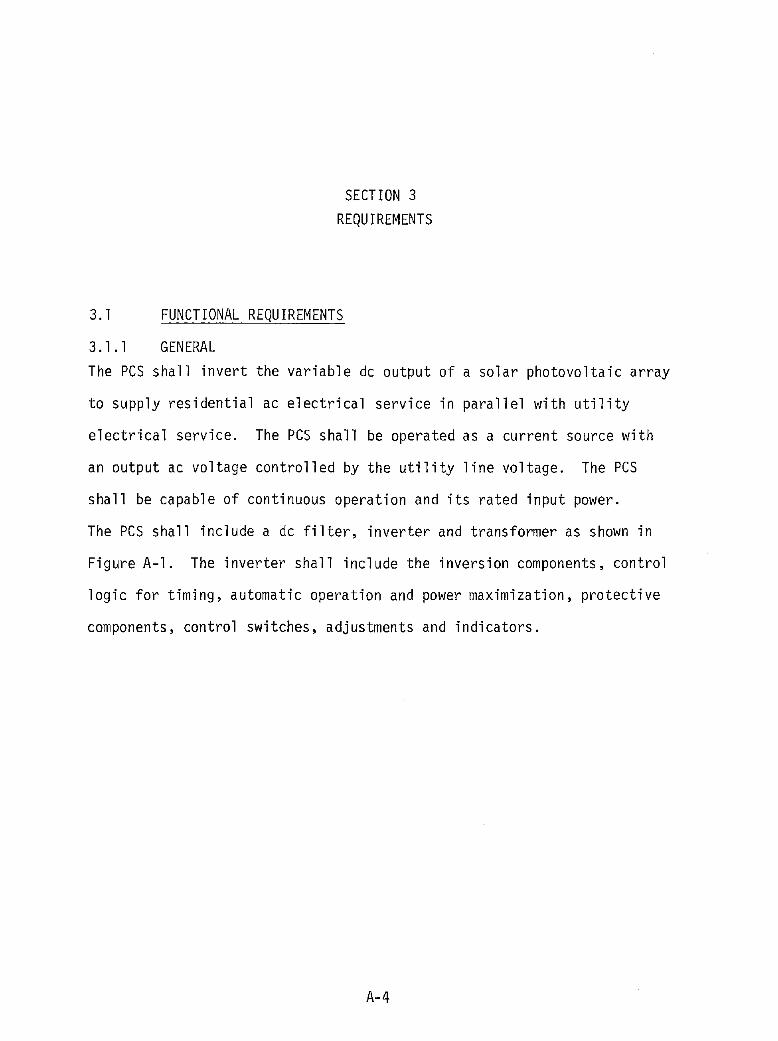
SECTION 3 REQUIREMENTS
3.1 FUNCTIONAL REQUIREMENTS
3.1.1 GENERAL The pes shall invert the variable dc output of a solar photovoltaic array
to supply residential ac electrical service in parallel with utility
electrical service. The pes shall be operated as a current source with
an output ac voltage controlled by the utility line voltage. The PCS
shall be capable of continuous operation and its rated input power.
The PCS shall include a dc filter, inverter and transformer as shown in
Figure A-l. The inverter shall include the inversion components, control
logic for timing, automatic operation and power maximization, protective
components, control switches, adjustments and indicators.
A-4
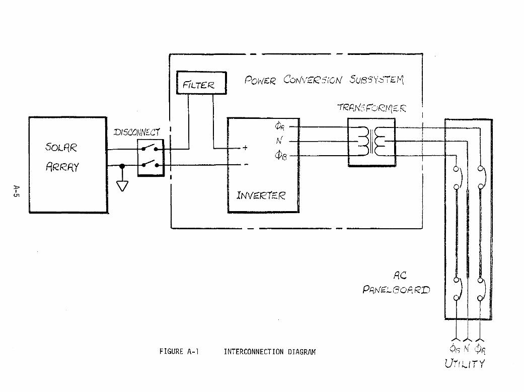
-r -0
0
.....o-c-. 1
-( v
I r-O
O-
-0
--<
I -
-<-L
r --
I----'---~
-1
Q
{y
q:
"'~
V
z. I
4l
\ \ I I
}-
c---
'I) z. lliJ
j
>-
C2
V
0
If") \:2
q:
(I)
CO I,"'
I'm
-1
I ::J
..:..:'.)
~
II) z:: er.-
I
I Z
~
l-I
Q
-..
I I
9 \i) I
~
ttl , 'Z
-'-~
I I
I 'I
~
Cll .(~
':z: Q
J
~
cv.
a::
~
C".!J
~
~
....
0
Cl
Q
~
I
z:
~
a
:-
....
I I
I-
• ~
U
L.LJ
I
z:
z:
a u a:: L.LJ
I I -
I-
z:
-I 1
....
at ~
~
li I
I
---
--
I
J
--~
L.LJ a:: :::J C".!J ....
}-I
',) ,4
.4 ~'l ~ ,
, I
u..
8 \J)
H>
R
-
C\L >
-cr
cr -l ~
S5 <J:!
CJ::"
I ....
A-5
3.1. 2 POWER CONVERSION SUBSYSTEM
The PCS shall provide the interface between the solar array dc output
and the residential electrical service. The PCS will automatically start
operation and connect the solar array to the service panel whenever the dc
bus voltage exceeds the specified minimum value. The PCS shall automatically
eisconnect the solar array from the residential electrical service in the
event of the loss of or out of tolerance utility line voltage or the
absence of real PCS output power.
3.2 PERFORMANCE REQUIREMENTS
3.2.1 INPUT POWER
The PCS shall be capable of continuous operation at an input dc level of
168~ volts and 26 amperes maximum; not to exceed an input power of 4 KVA.
3.2.2 DC TO AC INVERTER OPERATION
The dc to ac inverter shall provide to power conditioning necessary to
convert solar power to usable ac service. The dc to ac inverter section
of the PCS shall have the following operational characteristics.
3.2.2.1 Input Voltage Conditions
The PCS shall not initiate or continue dc to ac inverter operation whenever
the real output power is zero or the ac voltage lines are outside the voltage
limits required for normal correct commutation.
3.2.2.2 Startup/Shutdown Voltage
The PCS shall automatically initiate the closure of the output contactor
and the inversion process whenever the dc input voltage rises above 156 Vdc
and the ac utility service is within the voltage limits for normal correct
A-6
commutation. For voltages above 156 Vdc and less than 180 Vdc, the PCS
shall maximum power track to within ~ 1% of the maximum power. The
PCS shall automatically terminate the inversion process whenever the real
output power is zero or the ac utility service is outside the prescribed
voltage limits. Once operation has terminated due to the ac utility
service being outside the prescribed limits, the PCS shall remain "OFF"
for that period and for 4 minutes after the ac utility service return
within the prescribed limits.
3.2.2.3 MAXIMUM POWER FEATURE
The PCS shall operate at the instantaneous maximum power point operating + voltage of the solar photovo1taic array to within - 1 percent over the
input voltage range from 156 to 180 Vdc. The PCS shall operate at 156 Vdc
whenever the maximum power point is less than 156 Vdc and it shall operate
at 180 Vdc whenever the maximum power point is greater than 180 Vdc.
3.2.3 SHORT CIRCUIT PROTECTION
The PCS shall be equipped with protective circuits or devices which will
prevent damage to the PCS due to short circuit of the input or the output.
3.2.4 UNDERVOLTAGE AND OVERVOLTAGE PROTECTION
The PCS shall not be damaged by undervo1tage or overvo1tage conditions
at the PCS input or output.
A-7

3.2.5 OPEN CIRCUIT PROTECTION
The PCS shall not be damaged by open circuit conditions appearing at the
dc input or the ac output or both simultaneously.
3.2.6 EFFICIENCY
The PCS shall have an efficiency greater than 92% at the rated input
specified in Section 3.2.1. Operating power losses shall not exceed:
o 150 Watts-Tare loss
o 3 Volts-Thyristor bridge loss
o 0.150 Ohms-Resistive loss
3.2.7 HARMONICS
The PCS RMS total harmonic content of the output current shall be less
than 30% of the fundamental at the rated input specified in Section 3.2.1.
3.2.8 POWER FACTOR
The PCS power factor shall be greater than 60% at the rated input speci
fied in Section 3.2.1.
3.2.9 CONTROLS AND INDICATORS
The following controls and indicators shall be provided on the front panel
of the Inverter enclosure.
1. Inverter ON/OFF switch
2. Input current meter
A-8
3. Input voltage meter
4. PCS ON indicator light
3.3 DESIGN AND CONSTRUCTION
3.3.1 PHYSICAL CHARACTERISTICS
The PCS shall be housed in three wall or floor mounting enclosures meeting
the requirements of the National Electrical Code. Enclosures shall pro
vide access for installation, service, and maintenance. The three en
closures shall have maximum dimensions and weights as specified in
Table A-l.
TABLE A-l
PCS
Enclosure Height (in) Width
DC Filter 16 16
Inverter 30 24
Tran s former (5 KVA) 24 12
3.3.2 SERVICE CONDITIONS
Oeerating Ambient temperature
Relative humidity
Barometric pressure
A-9
(in) Deeth (i n) Weight
16 120
14 60
12 150
00 to 400 C
up to 95% noncondensing
520 to 790 mm Hg.
(1 b)

Non-Operating
Ambient temperature
Relative humidity
Barometric pressure
3.3.2.3 Shock and Vibration
_25 0 to 600C
up to 95% noncondensing
520 to 790 mm Hg.
The PCS shall be constructed to withstand normal handling and trans
portation environments. Special packaging or restraints required for
shipment shall be provided by the supplier.
3.3.3 GROUNDING
Input and output circuits shall not be grounded within the PCS enclosures.
Enclosure safety ground connections for interconnection to the service
ground will be provided and identified by the supplier. Neutral wiring
for the transformer secondary and primary may be specified as required.
3.3.4 LIFE
The PCS shall be designed for a 20-year life with a minimum of maintenance.
Any required preventive maintenance requirements shall be identified.
3.3.5 ELECTRICAL SAFETY
The pes design and construction shall conform to the applicable
requirements and practices of the National Electrical Code (NFPA 70).
A-IO
3.3.6 ELECTROMAGNETIC INTERFERENCE
Good design practices shall be followed to minimize elctromagentic
interference and susceptibility. Conducted interference of the PCS
shall be less than 200 microvolts between 5 kHz and 3 MHz.
3.3.7 AUDIBLE NOISE
Audible noise from the PCS shall be less than 50 dB one meter from the
equipment when mounted in accordance with installation instructions.
3.3.8 THERMAL DISSIPATION AND COOLING
The PCS shall be designed to operate in the environment defined in
Paragraph 3.3.2 without external cooling devices. Integral fans or
blowers, if required, shall utilize ambient air. Interlocks shall be
provided to shut the inverter down in case of failure of internal cooling
devices.
3.3.9 MAINTENANCE
Accessibility
The PCS shall be designed to allow ready access for installation, adjustment,
and maintenance. Insofar as possible, plug-in cards and modules shall be
utilitzed to facilitate troubleshooting and repair.
Replacement
A listing of parts required to support the unit will be provided in the
Operation and Maintenance Manual. This list shall identify those items
required for operational support and maintenance.
A-ll
3.3.10 DOCUMENTATION
Drawings
Schematics, wiring diagrams, and significant assembly drawing information
shall be included in the Operations and Maintenance Manual.
Operations and Maintenance Manual
An Operations and Maintenance Manual shall be provided. It shall consist
of the following:
1. General Description (a brief overall description of function and
performance).
2. Installation Instructions (mechanical mounting and electrical connections).
3. Adjustment Procedures (set-up and calibration information).
4. Operating Instructions (description of operating controls and sequences).
5. Parts List (a list of applicable parts and replacement items).
Provision shall be made for permanent storage of the Manual in the inverter
enclosure.
A-12

APPENDIX B
ELECTRICAL SYSTEM
INSTALLATION
SPECIFICATION

PASSIVE DESIGN NORTHEAST
RESIDENTIAL PHOTOVOLTAIC SYSTEM ELECTRICAL
INSTALLATION SPECIFICATIONS
PREPARED BY:
JOHNSON & STOVER, INC.
127 TAUNTON STREET
MIDDLEBOROUGH, MASSACHUSETTS 02346
FOR:
GENERAL ELECTRIC COMPANY ADVANCED ENERGY PROGRAMS DEPARTMENT
P. O. BOX 8555 PHILADELPHIA, PA 19101
PREPARED UNDER
SANDIA CONTRACT 13-8779
B-1

ELECTRICAL SPECIFICATIONS
FOR
DETAILED RESIDENTIAL PHOTOVOLTAIC
SYSTEM PREFERRED DESIGNS
PART 1:
1.1 1.2 1.3 1.4 1.5 1.6 1.7 1.8
1.9 1.10 1.11 1.12
PART 2:
DESIGN NO.4
INDEX
GENERAL REQUIREMENTS
GENERAL REFERENCES SCOPE OF WORK WORK NOT INCLUDED QUALITY ASSURANCE SUBMISSION DATA PRODUCT DELIVERY, STORAGE, OPERATING INSTRUCTIONS AND MANUALS ELECTRICAL CHARACTERISTICS TEMPORARY LIGHT AND POWER RECORD DRAWINGS SAFETY PRECAUTIONS
PRODUCTS
2.1 RACEWAYS AND FITTINGS
HANDLING MAINTENANCE
2.2 SUPPLEMENTARY STEEL, CHANNEL, AND SUPPORTS
2.3 CONDUCTORS 2.4 SAFETY SWITCHES 2.5 GROUNDING SYSTEM 2.6 PHOTOVOLTAIC EQUIPMENT
PART 3: EXECUTION
A-I A-I A-I A-I A-I A-2 A-2
A-2 A-2 A-3 A-3 A-3
A-4
A-4 A-5 A-5 A-5 A-7
3.1 WORK COORDINATION AND JOB OPERATIONS A-8 3.2 PLANS AND SPECIFICATIONS A-8 3.3 SYSTEM IDENTIFICATION A-8 3.4 WORKMANSHIP AND INSTALLATION METHODS A-8 3.5 ARRAY ERECTION PROCEDURE A-9 3.6 FCC CABLE INSTALLATION A-I0
B-2

RESIDENTIAL PROTOTYPE PHOTOVOLTAIC ELECTRICAL
INSTALLATION SPECIFICATIONS
PART 1: GENERAL REQUIREMENTS
1.1 GENERAL
A. This Specification includes all electrical work to install a roof-mounted photovoltaic (PV) system.
B. The system consists of several types of shingles which are to be interconnected by means of AMP Industries type FCC flat conductor cable.
1.2 REFERENCES
A. Cooperate and coordinate all electrical work with other contractors on site.
B. The complete structure will be constructed under another contract. The utility service will be in place along with the house circuit breaker panelboard and the customary house wiring system. The roof will be constructed and covered with roofing felt ready for shingle installation.
1.3 SCOPE OF WORK
A. Provide all labor, materials, equipment, and supervision necessary to complete the electrical work associated with a roof-mounted photovoltaic (PV) system, including all equipment identified.
1.4 WORK NOT INCLUDED
A. Construction of structure including roof underlayment and roofing felts.
1.5 QUALITY ASSURANCE
A. The work shall be executed Ln strict conformity with the latest edition of the National Electric Code and all local regulations that may apply. The installation of type FCC cable on a roof is not covered under Article 328 of the present National Electrical Code. The installation of the FCC cable shall be performed in strict accordance with manufacturer's recommendations and in accordance with the best practiees of the trade. In case of conflict between contract documents and a governing code or ordinance, the more stringent standard shall apply.
B-3

B. Unless otherwise specified or indicated. materials and workmanship shall conform with the following standards and specifications (latest edition):
1. National Electric Code.
2. Occupational Safety and Health Act.
3. Standards of Underwriters Labs (UL).
4. National Fire Protection Association (NFPA).
5. National Electrical Safety Code.
6. Local Codes.
C. Carry out tests. secure permits. pay fees, and arrange for all inspection of regulatory agencies for work under this section.
1.6 SUBMISSION DATA
A. Submit six (6) copies of all equipment to be incorporated into the work for approval prior to ordering same.
1.7 PRODUCT DELIVERY. STORAGE.HANDLING
A. All equipment. upon receipt. shall be inspected for damage and shall then be stored and protected from damage until project completion.
1.8 OPERATING INSTRUCTIONS AND MAINTENANCE MANUALS
A. Provide operating instructions to designated persons with respect to operation functions and maintenance procedures for all equipment and systems installed.
B. At project completion provide two (2) copies of bound brochures including all shop drawings. maintenance manuals, and spare parts lists.
1.9 ELECTRICAL CHARACTERISTICS
A. The PV array will produce an output of approximately 152.5 volts DC, which will then be inverted to a nominal voltage of 120/240 volts, sirigle phase. Capacity of the system is approximately 4755 watts.
B-4

1.10 TEMPORARY LIGHT AND POWER
A. Provide temporary electricity from the existing house service as required to allow completion of the work. Remove any temporary wiring when no longer required.
1.11 RECORD DRAWINGS
A. Maintain two (2) copies of the documents on site and record any revisions on one set of the job progresses. At project completion, transfer all changes to the other set.
1.12 SAFETY PRECAUTIONS
A. The contractor shall be completely responsible for all safety precautions to be taken by installers of the array. Refer to Appendix "PV Module and Installation Safety Notes".
B-S

PART 2: PRODUCTS
2.1 RACEWAYS AND FITTINGS
A. Conduit - General
1. No conduit shall be used smaller than 3/4" diameter. No conduit shall have more than four (4) 90 0 bends in anyone run, and where necessary pull boxes shall be provided.
2. Rigid PVC conduit shall be Schedule 40 UL listed o for 90 C. All fittings shall be solvent con-
nected. Provide threaded fittings where connected to metallic boxes. PVC conduit shall be Carlon. PVC conduit shall be used for exterior work and for raceways enclosing ground conductors.
3. Thin wall conduit (EMT), zinc coated steel, conforming to industry standards shall be used for all interior raceway systems. Fittings for EMT shall be compression or set-screw type. EMT shall be equal to Pittsburgh Standard Conduit Company, Republic Steel Tube, or Youngstown Sheet and Tube Company.
4. Conduit Fittings
a. Insulated bushings shall be provided on all raceways larger than 3/4".
'b. Access fittings shall be Type LL, LR, or LB as required, and shall be equal to Appleton, Crouse-Hinds, or RACO.
B. Outlet, Pull, and Junction Boxes
1. Each outlet box shall have sufficient volume to accommodate the quantity and size conductors entering the box in accordance with the requirements of the National Electric Code. Outlet boxes shall be pressed steel as manufactured by Steel City, RACO, or Appleton.
2. Pull Boxes or junction boxes shall be constructed of code gauge sheet metal of a size not less than required by the National Electric Code, if no size is indicated on the drawings, and shall have hinged doors.
2.2 SUPPLEMENTARY STEEL, CHANNEL, AND SUPPORTS
A. Furnish and install all supple~ntary steel, channel, and supports necessary for the proper mounting and support of all equipment. Provide minimum of 3/4" thick plywood backboards for mounting of all equipment at the equipment area.
B-6

B. All supplementary steel, channel, and supports shall be UL approved, be galvanized steel, and be as manufactured by Steel City, Unistrut, Power Strut, or Kindorf.
2.3 CONDUCTORS
A. All conductors shall be stranded copper of indicated on the drawings. All conductors Type THWN rated 90
0C for dry locations and
wet locations.
the size shall be o 75 C for
B. Conductors for use on the DC system shall be color coded red for positive and black for negative. AC conductors shall be color coded black for Phase A, red for Phase B, white for Neutral and green for Ground. DC conductors shall also be identified as DC by label markers.
C. All conductor terminations shall be made up by standard lug connections on equipment having same. Terminations made up for attachment to positive or negative transition blocks at the roof and the DC input inverter or other devices not having standard lugs shall be bolted type compression lugs as manufactured by Burndy, Thomas & Betts, or Panduit of tinplated copper. Bolts shall be 1/4-20 silicon bronze.
D. All terminations, other than located within enclosures, shall be insulated.
2.4 SAFETY SWITCHES
A. Safety switches shall be general duty 2-pole or 3-pole fused or non-fused in NEMA 1 or NEMA 3R enclosures as indicated on the drawings and shall be capable of being padlocked. Switches shall be equal to General Electric, Westinghouse, or Square D.
2.5 GROUNDING SYSTEM
A. There shall be four (4) isolated ground systems as follows:
1. Grounded Neutral: The house wiring system neutral shall be grounded only at the house panel by means of a #8 AWG connection between the panel neutral bus and the panel ground bus. The panel neutral block shall be isolated from the panel enclosure. A #8 AWG green insulated ground conductor shall then interconnect the panel ground block to the house ground bus.
B-7

2. Equipment Ground: A U8 AWG green insulated ground shall be looped between all equipment and shall be connected to each piece of equipment by means of a ground lug on the equipment. This conductor shall terminate at the house ground bus.
3. Varistor Ground: The U14 AWG green insulated ground conductor from the Varistor shall be connected through a separate conduit system with the array negative ground. This ground shall terminate at the house ground bus below the house service pane 1.
4. Array Negative Bus Ground: Provide a U8 AWG green insulated ground condu~tor from the line side of negative bus terminal at the exterior mounted overcurrent device to the house ground bus below the service panel. Run in PVC raceway along with Varistor ground.
5. House Ground Bus: Provide a 12" long 1/8" x I" copper ground bus on standoff insulators 12" above the floor below the AC panel. There shall be four (4) ground connections to the bus as follows: U8 AWG ground to house panel ground bus, U8 AWG ground to equipment ground system, U8 AWG ground at array negative bus, and U14 AWG ground for Varistor grounding. Provide a U8 AWG ground from the bus to the entering water service. In addition, provide a #8 AWG ground to a driven 3/4" x 10' long Copper Weld ground rod. This ground rod shall be located within the equipment area and shall extend 4" above the floor location.
6. Varistor Surge Protection
a. Furnish and install a Varistor for surge protection, which shall be mounted in a junction box sized as required on the drawings. The junction box shall be provided with an insulated mounting block and terminal bar isolated from the metal structure. A '14 AWG ground wire shall be tap-connected to the positive DC conductor which is to be protected by means of Burndy Servit type KS split bolt connector. This connector shall be insulated by taping. The load side U14 AWG ground from the Varistor shall be interconnected to the house ground bus located below the house panel.
b. Varistor on the positive DC side of the invertor shall be General Electric catalog number V275 LA40B.

B. Furnish and install a General Electric Lightning Arrester nippled to the side of the house service panelboard. Unit shall be catalog number TLP 175 and shall be connected with black leads to line buses and white to ground.
2.6 PHOTOVOLTAIC EQUIPMENT
A. The photovoltaic equipment including all shingle modules as shown on the drawings and including the roofing nails and split washers will be provided by General Electric Company.
B. The inverter package which forms an integral part of the generating and conversion system will be provided by General Electric Company and shall be installed by the Electrical Contractor.
C. FCC Cable System: The FCC cable, splice connectors, insulating patches, and crimping tool shall be as manufactured by AMP Industries and shall be furnished and installed by the Electrical Contractor.
D. Upon receipt of this equipment, each of the several parts shall be carefully examined to identify any possible shipping damages.
B-9

PART 3: EXECUTION
3.1 WORK COORDINATION AND JOB OPERATIONS
A. Be responsible for all equipment necessary for erection of the roof array including staging. Commencement of array erection signifies acceptance of the surface upon which the shingles are to be installed.
B. Coordinate all work prior to commencing with all existing conditions of the structure.
3.2 PLANS AND SPECIFICATIONS
A. The drawings showing layout of equipment, especially within the equipment area, show a suggested layout. Carefully check dimensions of all equipment and make any adjustments necessary to accommodate any variations.
B. Post the schematic diagram and equipment plan and elevation at a reduced scale under glass in the equipment area.
3.3 SYSTEM IDENTIFICATION
A. Provide screwed-on phenolic nameplates (black with white engraving) on all equipment. Differentiate between AC and DC equipment.
B. All raceways enclosing DC conductors shall be identified by appropriate labels.
3.4 WORKMANSHIP AND INSTALLATION METHODS
A. All work shall be installed in a first-class manner consistent with best current trade practices. All materials and equipment shall be securely installed plumb and/or level.
B. The inverter cabinet shall be mounted using Korfund vibration pads. All wiring connections to this cabinet shall be in flexible metal conduit.
C. All raceways shall be properly aligned, grouped, and supported at right angles to or parallel with the principal building members.
D. Any holes drilled through structure shall be neatly made and properly sealed after equipment installation.
B-IO

E. All wiring in panelboards and enclosures shall be neatly formed and grouped.
F. Be responsible for all safety precautions and rubbish removal. Leave site in clean condition.
3.5 ARRAY ERECTION PROCEDURE
A.
B.
C.
D.
The roof will be wider than the array layout. The array. therefore. shall be centered on the roof. The excess roof area at the sides will be covered by flashing prior to the installation of the shingles.
It is recommended that the type FCC cable rows be secured to the roofing felts in their proper allignment prior to commencing erection of the shingles. Dimensions of FCC cable rows detailed on drawing E-2 are to cable center lines and are given exactly to the height each shingle row will advance up the roof. The connection of the shingle positive and negative leads allows some variation in the exact location of the cables. The cable row dimensions are identified so as to clear all nail holes. The positive and negative bus c~ble rows should be installed prior to connecting any Shl~gles.. . The posltlve and negatlve leads of the shlngles shall be connected to the horizontal FCC cable rows prior to nailing the shingles in place. Nailing of the shingles shall be done by means of the nails and split washers provided. The opening in the washer shall be oriented in a straight vertical position to allow future removal of the shingle with the shingle removal tool. After the shingles have been secured in place. a bead of clear silicone sealant shall be applied to the bottom edge to prevent shingles lifting during wind conditions. The leads of the shingles are of sufficient length to allow removal of the shingle and reinstallation of a new single should it become necessary. After the shingle has been electrically connected and secured in place. the excess lead length shall be folded over on itself as indicated on Drawing E-6.
The positive and negative buses each consist of three (3) runs of FCC cable. The negative leads from the first row of "SCM" shingles and the positive leads of the top active row of "SCM shingles shall each be connected to a single run of FCC cable. The second and third layers of FCC cables are then interconnected to the first.
B-ll

E. The positive and negative buses shall be brought to a transition block enclosure located on the side wall via a pUllbox to be located below the clear story stool as indicated on the drawings. The bus cables shall be pulled through the pullbox and raceway to the transition block enclosure prior to connecting any shingles and before the final roof flashing is installed. Loosely secure the pUllbox to the vertical wall to allow flashing to be later slid behind the pullbox and over the FCC cables. After flashing in in place, resecure the pUllbox and seal at all edges in contact with flashing by means of silicone sealant.
3.6 FCC CABLE INSTALLATION
A. The horizontal and vertical rows of FCC cables shall be secured to the roofing felt by means of duct tapes approximately every 6'.
B. The positive and negative buses each consist of three (3) rows of FCC cable which shall be installed on top of each other. Tape the cables together periodically prior to securing to the roof.
C. The horizontal runs of cables shall be terminated with end seals.
D. Terminations and splicing shall be carried out in accordance with the manufacturer's recommended procedures. Special connector assemblies will be provided along with an installation crimping tool. The operation of the crimping tool is such that a positive connection is ensured prior to release of the tool jaws. Each splice or connection shall be insulated by means of a manufactured two-piece insulating patch.
E. Two transition blocks will be required and shall be mounted by the Electrical Contractor in an appropriately sized NEMA 3R hinge cover enclosure on the exterior.
B-12

APPENDIX C
INSTALLATION
SAFETY NOTES
APPENDIX C
INSTALLATION
SAFETY NOTES
It is recommended that the following safety precautions be enforced during all
phases of array installation or shingle module replacement. The PV array can
be installed during daylight hours. Each shingle module can generate a maxi-
mem potential of 25 Vdc. The series connection of modules up the slant height
of the roof will provide a potential of approximately 200 Vdc from eave to
ridge. Caution must be exercised to insure that no ~onductive path is provided
across module terminals by installation personnel or equipment. The following
list itemizes key safety requirements.
o No metal ladders or scaffolding should be used
o Installation should proceed only on a completely dry roofing surface
o The negative array ground terminal should not be connected until the electrical installation is complete
o The modules should be installed one course at a time from roof edge to roof edge, and not in any staggered pattern
o No electrically conductive material should be laid over the roofing surface during the installation
o The installation should be accomplished working from the roof surface as much as possible
o Grounded components, such as plumbing standard pipes, should not be touched and preferrably they should be covered with an electrical insulating cover during the installation
o Care should be exercised not to make physical contact with module terminations across a multiple of installed shingles
C-l

APPENDIX D
PERFORMANCE SIMULATION
MODEL AND INPUT DATA

APPENDIX D
PERFORMANCE S:IMULATION MODEL AND INPUT DATA
The simulation model is an adaptation of an analytical model developed during previous
DOE-sponsored studies. The model permits the assessment of system performance on an
annual basis using hourly SOLMET T:MY data tapes as the input. The program calculates,
for each daylight hour, the solar array operating point voltage and power using i:Ul iterative
calculation procedure based on models for current-voltage characteristics, array temper
ature, insolation, and battery state-of-charge, as described below. The losses in the in
verter are then determined based on solar array output power.
Solar Array Electrical Model
The synthesis of the solar array current-voltage characteristic, as a function of the total
insolation on the surface and the solar cell temperature, is modeled based on a single cell
characteristic which is represented by the following relationship:
Where
I =
V =
ISC =
C =
=
=
=
1= C.E.ISC -.2.....-1 £exp[K(V+IRS) J-1} Rp 0
Cell output current (Amperes/ cm2)
Voltage across cell terminals (Volts)
illumination current (virtually equal to short-circuit current) (Amperes/ cm2)
Ratio of the total insolation incident on the solar cells to the reference in
solation for the basic cell characteristics (100 mW/cm2)
Shunt resistance of the cell (Ohms-cm2)
Reverse saturation current of the ideal diode. characteristics
V oc (ISC - R )
P
exp (K V oc) - exp (K RS ISC)
D-1

K
RS
Voc
E
= = = =
Coefficient of the exponential (Volts-I)
Series resistance of the cell (Ohms-cm2)
Cell open circuit voltage (Volts)
Encapsulation loss or gain expressed as the fraction of bare cell short-cirtuit
current
ISC' RS' Rp. K and V oc are represented by polynominals of the form:
Y = aa + a1 T + a2T3 + a4T4 + a5T5 + asT6
where
T
Y
=
=
Solar cell temperature (oC)
Dependent variable (ISC. RS. ~, K, or V oc)
The values of the coefficients are selected to represent the characteristics of the solar
cells used in the module being considered. The total solar array output characteristics are
calculated based on the single cell characteristic by multiplying the voltages and currents by
the number of cells in series and parallel, respectively. In addition, the series resistance
of panel wiring is accounted for in the array characteristic.
Insolation Model
The value for total insolation (direct plus diffuse) on the sloped surface is obtained from
the values for the direct and diffuse components of the insolation on a horizontal surface as
obtained from the SOLMET TMY data tape by applying the following relationship:
= H R H [ (1 + cos (3) (1 - cos (3) ] Dill Dill + DIF 2 + p 2
where
H = Total insolation on the sloped solar array surface
HmF = Diffuse component of the solar flux incident on a horizontal surface
HDill = Direct components of the solar flux incident on a horizontal surface
D-2

f3 = angle between horizontal and solar array surface
p = the reflectance of the surrounding ground (a value of 0.4 was assumed in the
analysis)
The value of RDm is the ratio of the cosine of the solar angle of incidence (a i) on the
tilted solar array surface to the cosine of the solar angle of incidence (aW on a horizontal
surface. The value of cos a. is determined as a function of the day of year, time of day and 1
surface location and orientation in accordance with the following relationship:
cos a i = sin 6 [sin ¢ cos f3 - cos y cos ¢ sin f3 ]
+ sin y sin f3 cos 6 sin w
+ cos 6 cos w [cos y sin ¢ sin f3 + cos ¢ cos f3 ]
where
e i = Angle of incidence of beam radiation measured between the beam and the
normal to the solar array surface
¢ = Site latitude (north is positive)
6 = Solar declination angle
f3 = Angle between horizontal and solar array surface
y = Solar array surface azimuth angle (zero is due south, west of south is
positive)
w = Hour angle (zero is solar noon)
For a horizontal surface this expression reduces to:
cos eh
= sin 0 sin ¢ + cos 0 cos w cos ¢
D-3

Array Thermal Model
The temperature of a roof-moWlted solar cell module was calculated based on natural
convective cooling from the front surface of the module installation. Under this condition
the heat balance equation for the solar cell modules is given by:
where
RrOTAL = total insolation on the sloping solar array surface (W/m2)
p = ratio of solar cell area to total module area
O! = solar absorptance of solar cells s
Tamb = ambient temperature (oK)
Tsky = sky temperature (~
TR = temperature of the living space Wlder solar array (oK) = 2960K
Tcell = solar cell module temperature (oK)
h = convective film coefficient on the module front surface, (W/m2-KO) 0
h02 = convective film coefficient on the module back surface. (W/m2- oK)
E = hemispherical emittance of the front surface of the solar cell modules
(] = Stefan-Boltzmann constant
= 5.6697 x 10⁻⁸ W /m2 o!('!
The sky temperature, Tsky ' is calculated, using the relationship given in Reference 6:
= o 0552 (T )1.5 • amb
D-4

The front surface (ho) and back surface (ho2) film coefficients are calculated using te
lationships given in Reference 14.
= 1/3
1.247 «Tcell - Tamb) cos (3) + 3.81 V
= 1/3
1. 079 «Tcell - Tamb) cos (3) + 3.81 V
where
{3 = slope angle of roof (measured from horizontal)
V = wind speed (m/s)
Compared with data reported by JPL in Reference 14 the analytical model tends to over
predict cell temperature, with the result that predictions of cell output contain a conservative
bias.
Inverter Loss Model
The inverter loss model used in the battery storage analyses assumed a constant 87%
efficiency. A more sophisticated model of inverter losses, used in the feedback analyses and
accounting for constant loss, SCR bridge losses, and resistive losses, predicts efficiencies
ranging from 85 to 90% on an hourly basis with an annualized efficiency of 87%.
Battery Model
The charge and discharge voltage of a hybrid lead-acid battery has been modeled as a
function of battery state of charge (SOC) and instantaneous charge or discharge rate. Figure
D-1 shows a set of these characteristics as modeled based on data supplied by C&D Batteries
Division of the Eltra Company. The bottom set of curves are discharge characteristics with
discharge rates varying from O. 02C to 0.2C, where C is the cell energy capacity in Ampere
hours. The top set of curves are charge characteristics at the same rates, assuming that
recharge starts from the fully discharged condition. Different sets of characteristics are
modeled for various battery SOC conditions. Since the battery is modeled on these actual
characteristics, the round trip efficiency for the battery varies with battery capacity and col
lector area for the different cases analyzed. The average round trip efficiency was in the
D-5
2.80
2.. 60 CHARGE RATE
,-.. 2.40 til
~ 0 .c. w L'l
2.20 c(
~ 0 > -l -l W U 2.00 W L'l
~ W > c(
qo
1.60 DISCHARGE RATE
1.40~--------~--------~--------r-------~r-------~r-------~ . 1. 20 1.00 .80 . 60 .40 .20 .00
STATE OF CHARGE
Figure D-l. Battery Simulation Model
D-6

range of 75 to 88% which includes a constant average Ampere-hour charging efficiency of
0.952 based on the information from C&D Batteries. For a reference case of 65 m2 cell
area and a battery capacity of 20 kWh, the average round trip efficiency is 85%.
lliPUT DATA
The PV system simulation model requires input data, representing the PV system char
acteristics and hourly histories of local weather, insolation, and residential electrical and
space conditioning loads. Each of these input items is discussed below.
PV System Data
This data provides a description of the system in terms of its electrical characteristics.
It includes such information as the number of solar cells in each series circuit and the num
ber of parallel circuits. Cabling resistance and module interconnection resistance are
also input for determining power losses from the DC output to the inverter input. A series
resistance of 31 milliohms has been calculated for the current.
Weather Data
The National Climatic Center has recently made available rehabilitated, combined, hourly
solar radiation and meteorological data for twenty-six sites across the United States. The
solar radiation values from these SOLMET data sites have been corrected to reduce some of
the major data errors and gaps, and to provide non-measured direct radiation data on the
basis of the most recently developed correlation techniques with measured total radiation data.
The SOLMET records provide up to a twenty-three year record for the selected sites.
Sandia recently prepared a synthetic Typical Meteorological Year (TMY) for each of the
the twenty-six SOLMET sites. These TMY data tapes are based upon a selection of the most
typical January, February, etc., available in the years of record for each site. Typical
D-7
months were selected by a weighting technique for insolation, temperature and wind speed.
These TMY SOLMET records for ail 26 sites are available at GE. They provide a real
weather data base for solar system performance evaluation and comparison.
Electrical Load Data
Electrical loads for other than space conditioning are divided into three categories. The
first category is diversified or base load demand and includes lights and many miscellaneous
applications in the modern home. The second group includes cooking and clothes drying loads
while the third grouping consists of heating loads for domestic hot water. Profiles of the in
tegrated amount of energy used during each hour of the day for the various categories of energy
usage were developed for 1977 by utilizing a wide variety of references. From the data ex
amined, an annual usage of 5540 kWh was assumed representative of the diversified energy
usage by a typical family of four persons in 1977. Since lights and some appliances (e. g. ,
refrigeration equipment and HVAC auxiliaries) do have seasonal variations in their use, pro
files for the four seasons were developed. No significant regional variations were found. The
cooking and clothes drying profile was found to have negligible seasonal and regional variations,
and their annual load was determined to be 2220 kWh for the 1977 time period. An annual hot
water load was similarly determined at 4940 kWh but a regional correction was applied to both
the hourly profile and the annual value to account for difference in ground temperature across
the country. Seasonal variations were also incorporated.
All the profiles and annual values developed for 1977 were modified for prOjected usage
trends in 1986 according to the rationale indicated in Table D-l.
It should be noted that the prOjected decrease in baseload usage is 1. 8% per year
reflecting a more dedicated conservation program than had been assumed for previous
preferred designs. For the earlier designs, the prOjected baseload reduction was based
on the average of two projected reductions.
analysis used the higher projected reduction.
D-8
The current
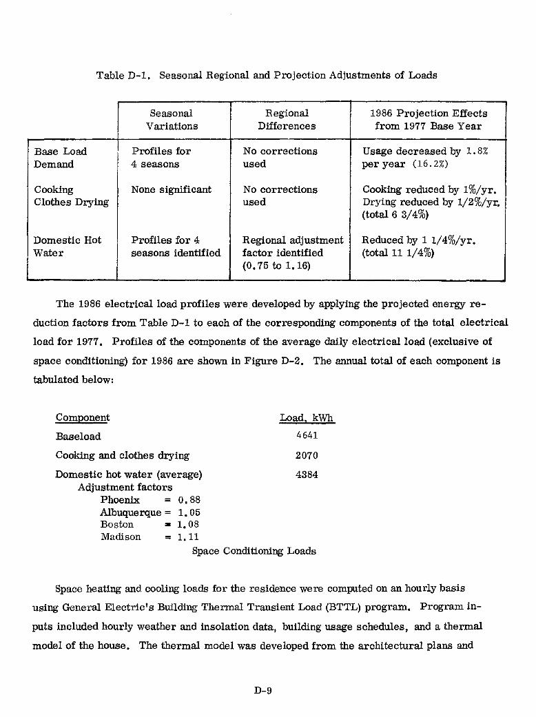
Table D-1. Seasonal Regional and Projection Adjustments of Loads
Seasonal Regional 1986 Projection Effects Variations Differences from 1977 Base Year
Base Load Profiles for No corrections Usage decreased by 1. 8%
Demand 4 seasons used per year (16.2%)
Cooking None significant No corrections Cooking reduced by 1 %/yr. Clothes Drying used Drying reduced by 1/2%/yr.
(total 6 3/4%)
Domestic Hot Profiles for 4 Regional adjustment Reduced by 1 1/4%/yr. Water seasons identified factor identified (total 11 1/4%)
(0.75 to 1.16)
The 1986 electrical load profiles were developed by applying the projected energy re
duction factors from Table D-1 to each of the corresponding components of the total electrical
load for 1977. Profiles of the components of the average daily electrical load (exclusive of
space conditioning) for 1986 are shown in Figure D-2. The annual total of each component is
tabulated below:
Component
Baseload
Cooking and clothes drying
Domestic hot water (average) Adjustment factors
Phoenix = O. 88 Albuquerque = 1. 05 Boston .. 1. 08 Madison = 1.11
Load, kWh
4641
2070
4384
Space Conditioning Loads
Space heating and cooling loads for the residence were computed on an hourly basis
using General Electric's Building Thermal Transient Load (BTTL) program. Program in
puts included hourly weather and insolation data, building usage schedules, and a thermal
model of the house. The thermal model was developed from the architectural plans and
D-9
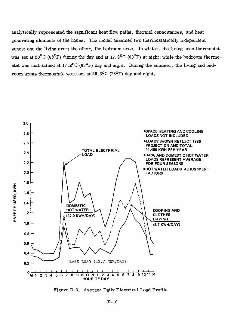
analytically represented the significant heat flow paths, thermal capacitances, and heat
generating elements of the house. The model assumed two thermostatically independent
zones: one the living area; the other, the bedroom area. In winter, the living area thermostat
was set at 20°C (68<7) during the day and at 17.2oC (63°F) at night; while the bedroom thermo
stat was maintained at 17. 2°C (63°F) day and night. During the summer, the living and bed
room areas thermostats were set at 25. 6°C (78oF) day and night.
:I:
~ c· w en ::l > t:1 a: w Z w
3.0
2.8
2.6
2.4
2.2
2.0
1.8
1.6
1.4
1.2
1.0
0.8
0.6
0.4
0.2
TOTAL ELECTRICAL LOAD
DOMESTIC HOT WATER
\ (12.0 KWH/DAY)
'I I \ , I ,
I I '" \ I \ I ... -1
BASE LOAD (12.7 KWH/DAY)
-SPACE HEATING AND COOLING LOADS NOT INCLUDED
-LOADS SHOWN REFLECT 1986 PROJECTION AND TOTAL 11,400 KWH PER YEAR
-BASE AND DOMESTIC HOT WATER LOADS REPRESENT AVERAGE FOR FOUR SEASONS
-HOT WATER LOADS ADJUSTMENT FACTORS
COOKING AND CLOTHES DRYING
(5.7 KWH/DAY)
Figure D-2. Average Daily Electrical Load Profile
D-10

The house was assumed to be occupied by a four-member family. The internal sensi
ble and latent heat generated by occupants, lighting, cooking and miscellaneous appliances
was derived from the hourly profiles of electrical loads and cooking loads established in
the previous section. The latent portion of the load was estimated from any showers, boiling
of water or other evaporative type processes occurring within the residence besides that due
to human presence.
The infiltration rate through window and door leakage was assumed to be a function of
wind speed. Since air flows are due to changes in air-stream static pressure, which, over
the surfaces of buildings, are approximately proportional to the square of wind speed, the
following equation was used in calculating infiltration gain ru the building:
Infiltration = 0.25 + 0.5 x ( m/sec wind speed )2, air change per hour 13.41
The basic house model can also be adapted to assess the effect of an attached green
house and large south facing glass areas including doors. The south facing glass area for
the basic house design was 7. 8 m2• For this passive house design, the south facing glass 2 2 2 2
area was 53.9 m (18.1 m for the greenhouse, and 28 m for the glass doors and 7. 8 m
for glass area),
For a passive design house, the model includes a third zone for the attached greenhouse.
In winter, the greenhouse thermostat was set to 32.20
C (900
F). The model assumed that
when the greenhouse temperature exceeded 32.20
C (900
F) during the heating season, a
blower would be activated to move the hot air in the greenhouse through ductwork either
to outlets distributed throughout the living space, when a heat load existed; or to thermal
storage, when no concurrent heat load existed. Night time heat loads were supplied from
storage when stored energy was available. During the cooling season, venting of the green
house and shading of the south facing glass doors neutralized the threat of solar heat gain.
The resulting space conditiOning loads predicted for the Boston residence by each model
are shown below.
D-ll

SPACE CONDITIONING LOADS, KWH MODEL
HEATING COOLING
BASELINE DESIGN 9759 2150
PASSIVE DESIGN 7260 2148
The effect of the greenhouse and the increased south facing glass area produced a
reduction of 25. 6% in annual heat load. The cooling load remained essentially unchanged,
since the solar gain associated with the additional south facing windows and greenhouse were
neutralized by shading and passive ventilation (open windows). The BTTL program pre
dicted heat load reduction of 25. 6% was compared with that predicted by the Passive Solar
Handbook (Reference D-IO) "rule of thumb." This rule related heat load reduction to the
increase in south facing glazing and distinguishes between site locations and the use of night
insulation on glazing. The heat load reduction "rule of thumb" is expressed as a correlation
in Figure D-3 for Boston and Madison. The abscissa in this figure is evaluated by dividing
the increased south facing window area by the floor area. The passive design house repre
sents a net increase in south facing window area of 38.3 m 2. The floor area of the house is 2
148.7 m. This combination of increased south facing window area and floor area translate
to a "rule of thumb" prediction of 23% reduction in heat load for Boston, which is about 10%
below the prediction based on the BTTL results. Notice that the "rule of thumb" correlation
also permits the evaluation of glazing with night insulation, which results in additional reduc
tions in heat load. For the passive design house, the heat load reduction with night insulation
increases from 23% to 58%. For this analysis, night insulation was assumed and the "rule of
thumb" correlation was assumed; however, a conservative value of 48% for the heat load
reduction was used in the hourly adjustment of the baseline heat load to yield an annual heat
load of 5075 kWh.
For the design house in Madison, the passive solar heat load reduction amounted to 57%
based on the "rule of thumb" correlation (see Figure D-3). As with the Boston house, a con
servative value of 48% was used in the analysis for heat load reduction.
D-12
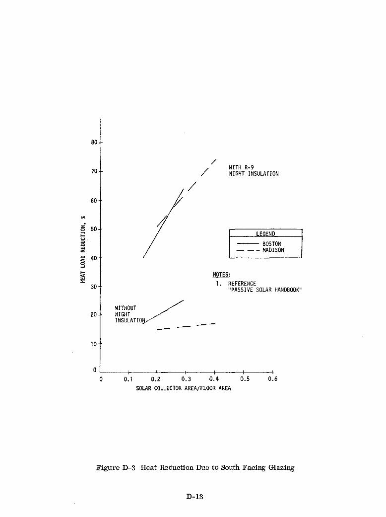
... . z 0 .... l-t.> => Q LU
'" Q
C§ ..J
I-00: LU ::
80
70
60
so
40
30
20
10
/
/ WITH R-9 NIGHT INSULATION
/
LEGEND
--- BOSTON - -- MADISON
NOTES:
WITHOUT / NIGHT INSULATIO --
1. REFERENCE "PASSIVE SOLAR HANDBOOK"
--
o ~ ____ +-____ +-____ ~ ____ -+ ____ ~ ____ ~
o 0.1 0.2 0.3 0.4 O.S 0.6 SOLAR COLLECTOR AREA/FLOOR AREA
Figure D-3 Heat Reduction Due to South Facing Glazing
D-13

Monthly space heating and cooling load profiles for the single family residence in
Boston and Madison are listed in Table D-2. It is important to note that these space condi
tioning loads are loads which are satisfied by the heating and cooling equipment. In the
all-electric house, the heat pump supplies these loads and creates an electrical demand
equivalent to the space conditioning load divided by the heat pump COP. The monthly pro
files of heat pump electrical requirements are shown in Figure D-3 for Boston and Madison.
Both the space conditioning loads and the heat pump electrical requirements reflect the
geographic differences between Boston and Madison, which are at the same latitude, but are
950 miles apart. Boston has higher cooling loads than Madison; however, Madison has the
greater heating loads. The space conditioning demands are calculated hourly during the
simulation and these plots provide the monthly summaries.
D-14
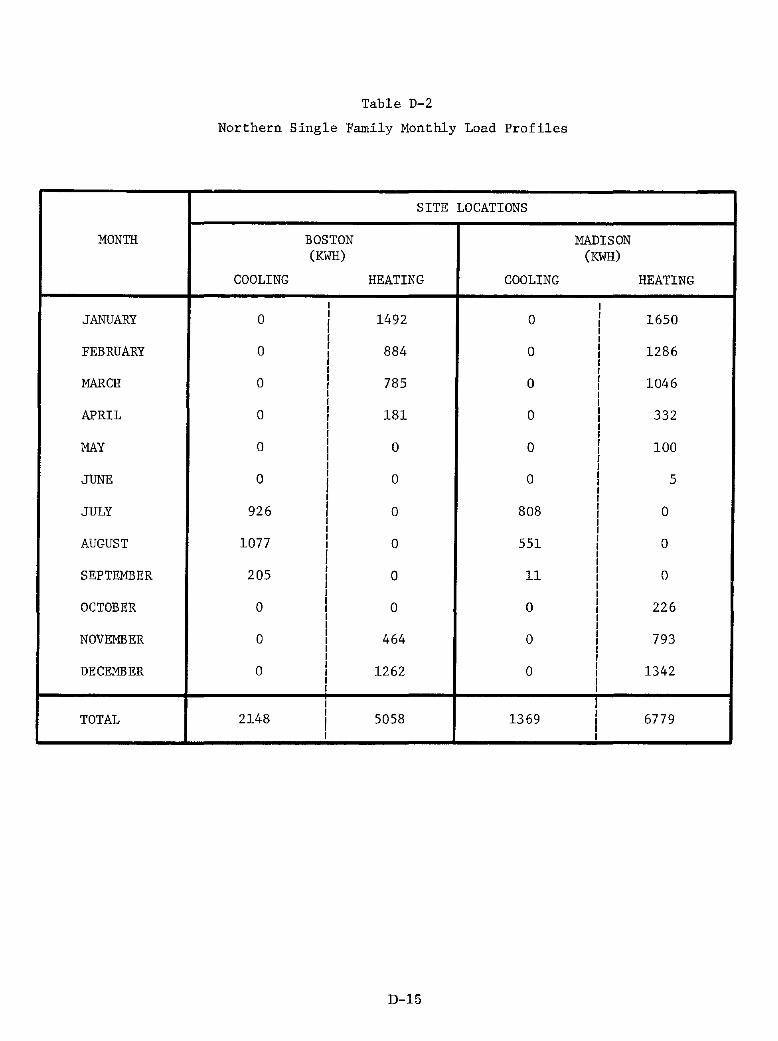
Table D-2
Northern Single Family Monthly Load Profiles
SITE LOCATIONS
MONTH BOSTON MADISON (KWH) (KWH)
COOLING HEATING COOLING HEATING
I I
JANUARY 0 I 1492 0 I 1650 I I I
I I FEBRUARY 0 I 884 0 I 1286 I I
I I I I
MARCH 0 I 785 0 I 1046 I I I I I I
APRIL 0 I 181 0 I 332 I I I I I I
MAY 0 I 0 0 I 100 I I I f I f
JUNE 0 I 0 0 f 5 f f f f f I
JULY 926 I 0 808 0 I I I
AUGUST 1077 I 0 551 0 I I I
SEPTEMBER 205 I 0 11 0 I I I
OCTOBER 0 I 0 0 I 226 I I I I I I
NOVEMBER 0 I 464 0 I 793 I I I I I I
DECEMBER 0 I 1262 0 I l342 I I I I I I
I I TOTAL 2148 I 5058 l369 6779 I I I
I I
D-15
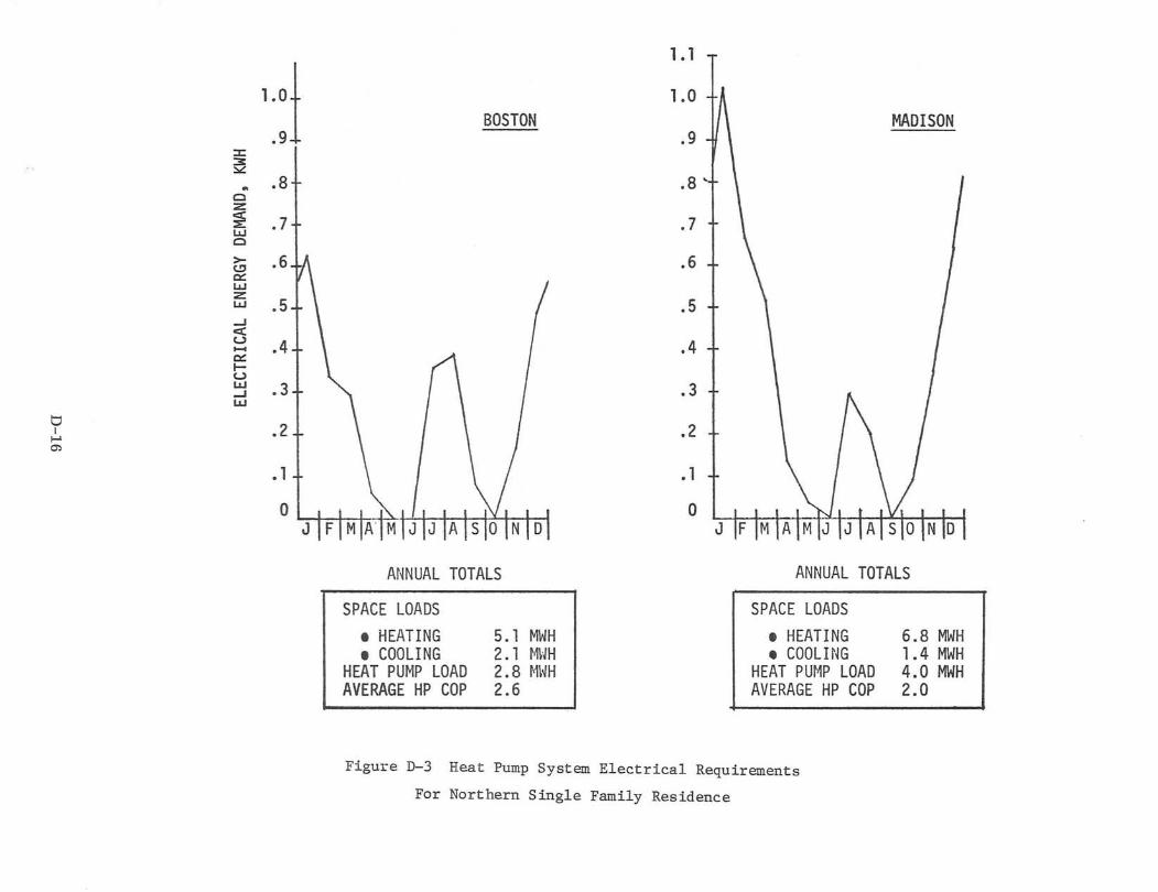
1.°1 .9
::z:: ~
.. .8+ Cl :z ~ .7+ lLJ Cl
>- .61/\ to!' a: lLJ :z .5+ \ lLJ
...J c( u .4.i \ -a: t-u lLJ .3.i ...J lLJ
t;) .2 L I
....... 0':>
.1 t o I
1.1
1.0 BOSTON 1/\ MADISON
.9
.8 '
.7
.6
I .5
.4
"- \ .3
\ \ .2
,\./. ,V, • 1
I 0
ANNUAL TOTALS ANNUAL TOTALS
SPACE LOADS • HEATING • COOLING
HEAT PUt>'IP LOAD AVERAGE HP COP
5.1 MWH 2. 1 t'1~m 2.8 r\1~m 2.6
SPACE LOADS • HEATING • COOLING
HEAT PUt~P LOAD AVERAGE HP COP
Figure D-3 Heat Pump System Electrical Requirements
For Northern Single Family Residence
6.8 MWH 1.4 MWH 4.0 MWH 2.0

APPENDIX E
ECONOMIC MODEL AND ASSUMPTIONS
ECONOMIC METHODOLOGY

APPENDIXE
ECONOMIC MODEL AND ASSUMPTIONS
Economic Methodology
Many of the simple investment evaluation techniques, such as payback time or simple
return, suffer from two major drawbacks: life of the investment is not considered, and un
even costs and/or benefit streams cannot be handled.
The second item is of critical Importance to alternate energy systems since virtually
every economic scenario projects rising energy prices and therefore a steadily increasing
benefit stream from an alternate energy system. For this reason, considerable effort has
been made to stress ''life cycle costing" for alternate energy systems. The following sections
describe the life cycle costing model used in system sizing analysis.
Levelized Annual Cost
True life cycle cost analysis must necessarily consider the timing of costs and benefits
as well as the magnitude. A method employed in previous General Electric solar and wind
energy programs is to compare Levelized Annual Benefits (LAB), representing system energy
savings, with the Levelized Annual Cost (LAC), the levelized dollar amount required to own,
operate, and maintain a system during each year of the life of the system. Specifically, the
levelized annual cost accounts for:
1. "Paying off" system capital costs (mortgage principal)
2. Paying mortgage interest
3. Paying property taxes and insurance
For cost evaluation and comparison of systems for future implementation, it is appro
priate to express the levelized annual cost (LAC) referenced to a particular year, e. g., 1980.
The result is the levelized annual cost in constant (base year) dollars given by:
E-l

CRF' LAC (constant ) = CRF x FCR x I + AOC
where I is the capital cost of the solar system and AOC is the annual system operating cost
which includes operation and maintenance and insurance. The parameter FCR is the fixed
charge rate and represents the yearly cost of ownership, expressed as a percent of the cap
ital cost, I. These costs consist of mortgage interest, principal and property taxes. The
parameter CRF is the capital recovery factor, defined as the uniform periodic payment (as a
fraction of the original principal) that will fully repay a loan (including all interest) in yearly
periods over the loan lifetime at a specified yearly interest rate. The interest rate r used
to calculate CRF is called the discount rate and for the homeowner is equal to the after-tax
interest rate of the mortgage.
The relation expressing CRF as a function of r and system lifetime N is given as
N CRF = r(1+r~
(1+r) -1
The parameter CRF' is the corresponding capital recovery factor in constant (base
year) dollars. CRF' is based on the real (or inflation adjusted) discount rate, r', defined as
r'= 1 + r_ - 1
l+g
where g is the general inflation rate. The equation for CRF also applies for CRF' with
r' replacing r.
It should be noted that the LAC equation applies only to those systems without storage
batteries since no replacement costs are necessary. For systems with storage, an addition
term of the form
CRF' xl'
B (1 + r) 11
E-2

must be added to account for the replacement of the battery in the eleventh year (e. g., for
a battery life of 10 years). Here, I'B is the cost of the replacement battery in constant
1980 dollars.
Levelized Annual Benefits
The comparison of the energy cost savings of the solar system to the levelized annual
cost is accomplished by computing the levelized annual benefits (LAB) for the energy savings.
LAB is inherently a function of present and projected energy prices and may be expressed by
CRF' LAB (constant ) = CRF xMxp xE
o 0
where E represents the annual energy saved by the solar system, M is an energy saving o
multiplier which is defined as the leve lized value of an escalating cost stream which accounts
for the rate of energy price escalation over the lifetime of the system, and p is the energy o
price in year zero (for a 1986 start, year zero becomes 1985). For stand-alone systems,
minimum monthly energy charges are included as a benefit in the computation of LAB.
The multiplier M is a function of energy price escalation rate (f), system lifetime (N),
and discount rate (r), and is expressed as
M = r (1 + f) r - f [ (l+r t -(l+;t 1 *
(1 + r)N - 1
The energy price in year zero (p ) is related to the energy price in constant (base year) a
dollars per energy unit (P) through the expression
where ~ is the number of years from the base year to year zero (value of 5 was used for
a 1986 start with a base year of 1980).
*When r=f: M~RF. N
E-3

The economic viability of a sys~em can be measured through the use of the cost-to-benefit
ratio, which is defined as the ratio of the levelized annual cost to the levelized annual benefit.
The system can be economically viable when the cost-to-benefit ratio is less than unity. The
break-even system cost occurs when the ratio is exactly unity, i. e., when LAC and LAB are
equal.
Economic Assumptions
This subsection spells out the basic assumptions that will be used in the economic analysis
of PV residential systems. These assumptions concern the price of electricity in the designa
ted regions for the 1986 time period and system capital cost. Also considered are assumptions
regarding inflation, interest, and tax rates insofar as they will affect economic comparison
results.
Model Assumptions
In order to utilize the cost-to-benefit ratio for system sizing studies, a set of economic
assumptions were developed. These fJ,ssumptions are summarized in Table E-l. Most of
these assumptions are consistent with assumptions utilized in previous residential studies as
Reference 1. All of the economic calculations were completed for a 1986 start in constant
1980$. The overall average inflation rate of 5 percent was assumed through the time frame
of the analysis. This value is low according to current rates but since the cost-to-benefit
ratio analysis becomes independent of the inflation rate and to maintain similarity to previous
work, this value was used. In addition, a resultant homeowner mortage rate of 10 per cent
for a 20-year loan was assumed with a marginal income tax rate of 35 per cent for the home
owner. This is equivalent to a taxable income of approximately $25,000 at present tax rates.
A 20-year life will be assumed for the solar systems of interest with a battery life of 10 years.
Since several states and local communities have already exempted solar systems from prop
erty tax, no additional property tax will be assumed. These figures imply an annual cost
or "fixed charge" of about 9. 1% of the initial photovoltaic system cost. Annual operating
costs are assumed to be $100/year for operation and maintenance and O. 5% of system cost
E-4
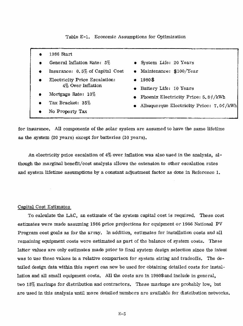
Table E-1. Economic Assumptions for Optimization
• 1986 Start
• General Inflation Rate: 5% • System Life: 20 Years
• Insurance: 0.5% of Capital Cost • Maintenance: $100/Year
• Electricity Price Escalation: • 1980$ 4% Over Inflation
• Battery Life: 10 Years
• Mortgage Rate: 10% • Phoenix Electricity Price: 5. 8 ¢ /kWh
• Tax Bracket: 35% • Albuquerque Electricity Price: 7.0¢/kWh
• No Property Tax
for insurance. All components of the solar system are assumed to have the same lifetime
as the system (20 years) except for batteries (10 years).
An electricity price escalation of 4% over inflation was also used in the analysis, al
though the marginal benefit/cost analysis allows the extension to other escalation rates
and system lifetime assumptions by a constant adjustment factor as done in Reference 1.
Capital Cost Estimates
To calculate the LAC, an estimate of the system capital cost is required. These cost
estimates were made assuming 1986 price projections for equipment or 1986 National PV
Program cost goals as for the array. In addition, estimates for installation costs and all
remaining equipment costs were estimated as part of the balance of system costs. These
latter values are only estimates made prior to final system design selection since the intent
was to use these values in a relative comparison for system sizing and tradeoffs. The de
tailed design data within this report can now be used for obtaining detailed costs for instal
lation and all small equipment costs. All the costs are in 1980$ and include in general,
two 15% markups for distribution and contractors. These markups are probably low, but
are used in this analysis until more detailed numbers are available for distribution networks.
E-5

The system capital costs were divided into an array cost, power conditioning
cost, and balance of system costs. The balance of system costs were further separated
into a fixed cost (i.e., however small a PV installation, a minimum amount of equip
ment, and thus, cost, is required independent of ~ystem size) and a variable cost
based on system size. The variable, or area-related costs of a photovoltaic system
include the cost of modules, array installation, and a portion of the power condition
ing. The fixed costs obviously include the roof to load wiring, switchgear and power
conditioning installation. There are other less obvious fixed costs, however.
For example, the cost of a power conditioning unit will include basic labor,
cabinet and parts costs independent of size. In the area of operation and mainten
ance, a large fraction of the cost will not be area related. This would include
almost all PCU and switchgear maintenance. For any given system, more or less fixed
costs may be present, but the general contributors will remain.
The array cost assumed is the National PV Program goal of 70¢/peak watt or $700/
kWp factory price. Including the markups, the cost is $925/kWp on site. The balance
of system costs were made up of array installation estimates, power conditioning sub
system costs, and remaining equipment costs. The array installation cost estimate
was based on labor and material estimates from the 1978 Building Cost File Index for
conventional asphalt shingle installation and increased by an assumed factor of 3 to
account for the additional complexity of the PV shingle installation. The resulting
cost is $35.35/m2 per unit array installation.
Labor and material credit for weather tight replacement of the conventional shin
gles was then given at $12.29!m2 for a net array installation cost of $23.06!m2 • These
values are consistent with residential array installation cost estimates developed by
Burt Hill Kosar Rittleman Associates, Reference 7, where non-optimized flat PV panel
installation costs were approximately $40/m2 and roof credits for integrated arrays
were approximately $11/m2
.
The power conditioning subsystem cost estimates were based on cost projections from
E-6
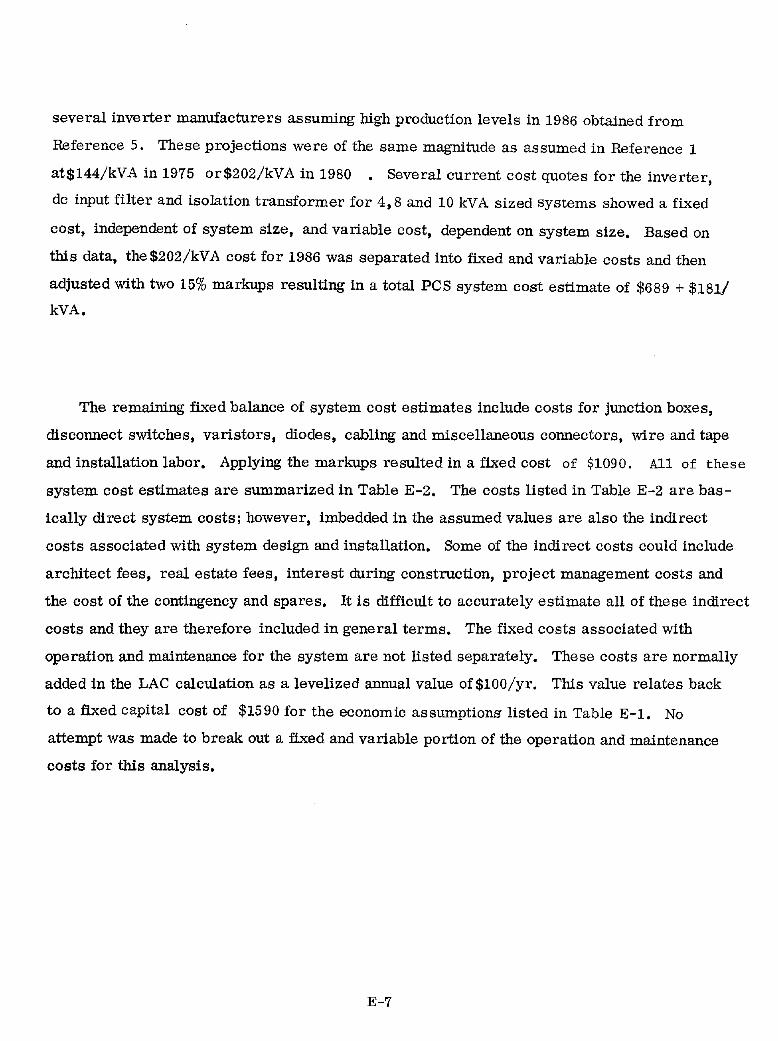
several inverter manufacturers assuming high production levels in 1986 obtained from
Reference 5. These projections were of the same magnitude as assumed in Reference 1
at$144/kVA in 1975 or$202/kVA in 1980 • Several current cost quotes for the inverter,
dc input filter and isolation transformer for 4,8 and 10 kVA sized systems showed a fixed
cost. independent of system size, and variable cost. dependent on system size. Based on
this data. the $202/kVA cost for 1986 was separated into fixed and variable costs and then
adjusted with two 15% markups resulting in a total PCS system cost estimate of $689 + $181/
kVA.
The remaining fixed balance of system cost estimates include costs for junction boxes,
disconnect switches, varistors, diodes, cabling and miscellaneous connectors. wire and tape
and installation labor. Applying the markups resulted in a fixed cost of $1090. All of these
system cost estimates are summarized in Table E-2. The costs listed in Table E-2 are bas
ically direct system costs; however, imbedded in the assumed values are also the indirect
costs associated with system design and installation. Some of the indirect costs could include
architect fees. real estate fees, interest during construction, project management costs and
the cost of the contingency and spares. It is difficult to accurately estimate all of these indirect
costs and they are therefore included in general terms. The fixed costs associated with
operation and maintenance for the system are not listed separately. These costs are normally
added in the LAC calculation as a levelized annual value of$100/yr. This value relates back
to a fixed capital cost of $1590 for the economic assumptions listed in Table E-l. No
attempt was made to break out a fixed and variable portion of the operation and maintenance
costs for this analysis.
E-7
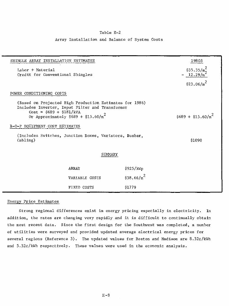
Table E-2
Array Installation and Balance of System Costs
SHINGLE ARRAY INSTALLATION ESTIMATES
Labor + Material Credit for Conventional Shingles
POWER CONDITIONING COSTS
(Based on Projected High Production Estimates for 1986) Includes Inverter, Input Filter and Transformer
Cost = $689 + $18l/kVA 2 Or Approximately $689 + $15.60/m
B-O-P EQUIPMENT COST ESTIMATES
(Includes Switches, Junction Boxes, Varistors, Busbar, Cabling)
ARRAY
VARIABLE COSTS
FIXED COSTS
Energy Price Estimates
SUMMARY
$925/kWp
2 $38.66/m
$1779
1980$
2 $35.35/m2 l2.29/m
2 $23.06/m
$689 + $15.60/m2
$1090
Strong regional differences exist in energy pricing especially in electricity. In
addition, the rates are changing very rapidly and it is difficult to continually obtain
the most recent data. Since the first design for the Southwest was completed, a number
of utilities were surveyed and provided updated average electrical energy prices for
several regions (Reference 3). The updated values for Boston and Madison are 8.32~/kWh
and 5.32~/kWh respectively. These values were used in the economic analysis.
E-8

APPENDIX F
RECTANGULAR PV SHINGLE MODULE CONSTRUCTION DETAILS
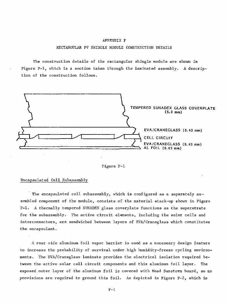
APPENDIX F
RECTANGULAR PV SHINGLE MODULE CONSTRUCTION DETAILS
The construction details of the rectangular shingle module are shown in
Figure F-I, which is a section taken through the laminated assembly. A descrip
tion of the construction follows.
Figure F-I
Encapsulated Cell Subassembly
TEMPERED SUNADEX GLASS COVERPLATE (5.0 mm)
EVA/CRANEGLASS (0.43 mm)
CELL CIRCUIT
EVA ICRANEGLASS (0.43 mm) AL FOIL (0.03 mm)
The encapsulated cell subassembly, which is configured as a separately as
sembled component of the module, consists of the material stack-up shown in Figure
F-I. A thermally tempered SUNADEX glass coverplate functions as the superstrate
for the subassembly. The active circuit elements, including the solar cells and
interconnectors, are sandwiched between layers of EVA/Craneglass which constitutes
the encapsulant.
A rear side aluminum foil vapor barrier is used as a necessary design feature
to increase the probability of survival under high humidity-freeze cycling environ
ments. The EVA/Craneglass laminate provides the electrical isolation required be
tween the active solar cell circuit components and this aluminum foil layer. The
exposed outer layer of the aluminum foil is covered with Mead Sunstorm board, so no
provisions are required to ground this foil. As depicted in Figure F-2, which is
F-l
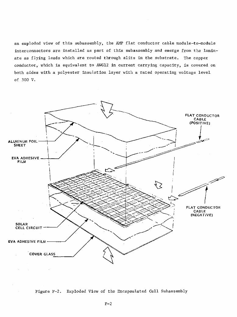
an exploded view of this subassembly, the AMP flat conductor cable module-to-module
inter connectors are installed as part of this subassembly and emerge from the lamin
ate as flying leads which are routed through slits in the substrate. The copper
conductor, which is equivalent to AWG12 in current carrying capacity, is covered on
both sides with a polyester insulation layer with a rated operating voltage level
of 300 V.
ALUMINUM FOIL--+--J
SHEET
EVA ADHESIVE _-+_.-J FILM
SOLAR CELL CIRCUIT----'
EVA ADHESIVE FILM -----'
Figure F-2. Exploded View of the Encapsulated Cell Subassembly
F-2
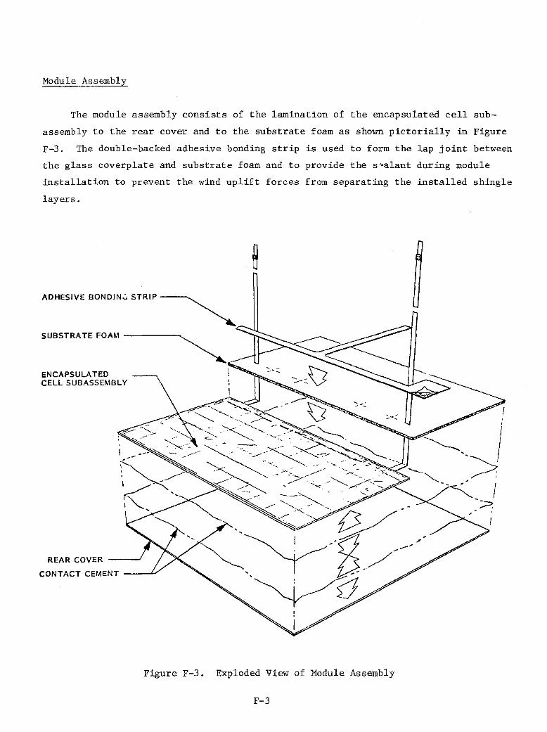
Module Assembly
The module assembly consists of the lamination of the encapsulated cell sub
assembly to the rear cover and to the substrate foam as shown pictorially in Figure
F-3. The double-backed adhesive bonding strip is used to form the lap joint between
the glass coverplate and substrate foam and to provide the s~alant during module
installation to prevent the wind uplift forces from separating the installed shingle
layers.
ADHESIVE BONDIN':; STRIP ~
SUBSTRATE FOAM ~
ENCAPSULATED I CELL SUBASSEMBLY
REAR COVER
CONTACT CEMENT __ -0./
Figure F-3. Exploded View of Module Assembly
F-3

Mead Sunstorm board, which is a 2.0 rom thick weather-resistant solid fiberboard
material, is used as the rear cover. This material is of a laminated construction
with the core composed of highly sized reclaimed kraft fibers. All glue lines are
bonded with waterproof PVA adhesive. Both outer facings of Sunstorm board are
white -- wet strength beached vergin kraft lining paper. This liner has a mold in
hibitor added to reduce the possibility of mildew in exterior applications. Also,
a clay coating is applied to facilitate high quality silk screen printing and various
modes of paint application. The outer facings are secured to the core with a film
of polyethylene. This film serves as a barrier, retarding water and moisture ab
sorption, while giving added dimensional stability to the overall product. The outer
skin is B.F. Goodrich reinforced Hypalon Flexseal which covers a closed-cell poly
ethylene foam to provide uniform thickness of the tub. Scotch-Grip Adhesive 4230
(3M Co.) is a contact cement used for the laminating adhesive for this assembly. It
bonds the aluminum foil vapor barrier of the encapsulated cell subassembly to the
rear cover and bonds the rear cover to the substrate foam. It is an economical,
water-dispersed adhesive offering excellent wet strength, and resistance to tempera
tures as high as l630 C, and to high humidity and aging effects. This adhesive is
applied with low·pressure spray equipment, and produces no toxic or flammable noxious
fumes.
The adhesive bonding strip is used to form the lap joint between the substrate
foam and the glass coverplate and to bond and seal the overlapped joint between
courses on the roof by bonding to the rear cover of the upper layer. A 3M Scotch
Mount double-coated tape #4008 is used for this application on the basis of its
resistance to water absorption, and outdoor weathering involving a temperature range
of -40 to 950 C with high humidity. This tape is applied to the outer surface of the
substrate foam and glass coverplate leaving the liner in place on the exposed tape
surface until such time as the overlapping shingle course is laid down.
Flat Conductor Cable Assemblies
Two flat conductor cable (FCC) assemblies, which are manufactured by AMP, Inc.,
are provided in each module. These FCC assemblies consist of a polyester insulated
copper foil strip (equivalent to AWG 12) 16 rom (0.625 inch) wide by 0.13 mm (0.005
inch) thick, which have varying lengths depending on whether the assembly is to be
F-4

used as the positive or negative lead. The outer end of each FCC is terminated
with a patented, crimp-type connector which was developed, and has been UL-approved,
for under carpet ac power distribution systems. The stripped end of each FCC is
soldered to the appropriate cell interconnectors to form the terminations for the
module. Strain relief of these solder joints is provided by bonding to FCC within
the substrate lamination between the rear core and the foam core.
Module-to-Module Interconnects
The electrical connection of the negative terminal of one module to the posi
tive terminal of another module is accomplished through crimp connections of the
splice terminals to a common FCC carrier.
F-5
RESIDENTIAL REPORTS DISTRIBUTION
D ISTR I BUT ION:
TID-4500-R66, UC-63a (224)
L. A. Barrett (25) Department of Energy Division of Photovoltalc Energy Systems Forresta I BI dg. 1000 Independence Ave. SW Wash I ngton, CC 20585 Attn: M. B. Prince
V. Rice A. Krantz
Department of Energy D I vi s Ion of Act (ve Heat I ng and Coo II ng Office of Solar Applications for Bldgs. Wash I ngton, CC 20585 Attn: Robert D. Jordon, Director
Department of Energy Division of Passive and Hybrid Office of Solar Applications Washington, CC 20585 Attn: Michael D. Maybaum, Director
Jet PropulsIon Laboratory (15) 4800 Oak Grove DrIve Pasadena, CA 91103 Attn: R. V. Pawe II (4)
R. Ferber K. Volkmer W. Ca II aghan R. Ross R. S. Suglmura R. Weaver S. Krauthamer A. Lawson
Jet Propu 1 s I on Laboratory Solar Data Center MS 502-414 4800 Oak Grove Drive Pasadena, CA 91103
R. Tl!bors (2) MIT-Energy Laboratory E40.172 Cambridge, MA 02139
Dist-l
Solar Energy Research Institute (6) 1536 Co I e Bou I eva rd
Go I den, CO 80401 Attn: D. Feucht
S. Sill man T. Basso M. DeAnge 11 s G. Nuss R. DeBI as 10
SER I, LIbrary (2)
1536 Cole Boulevard, Bldg. #4 Go I den, CO 80401
SERI Mall Stop 15-3 1617 Cole Blvd. Go I den, CO 80401
NASA Lewis Research Center 21000 frookpark Laboratory Cleveland, OH 44135
Florida Solar Energy Center 300 State Road 401 Cape Canavera I, FL 32920 Att n: S. O1andra
Effil (3)
P.O. Box 10412 Pa I 0 AI to, CA 94303 Attn: Frank Goodman
Edgar Demeo Roger Tay I or
House Science and Technology Committee Room 374-B Rayburn Bu II ding Wash t ngton, CC 20515 Attn: Don Teague
MIT-Uncoln Laboratory (6)
p.O. Box 73 Lexl ngton, MA 02173 Att n: M. Pope
M. Russe II (2) E. Kern (3)

Off Ice of Technology Assessment
U.S. Congress
Wash I ngton, OC 20510
New Mexico Solar Energy Inst. (25)
New Mexico State University
Box 3S0L Las Cruces, NM 88003
Attn: John Schaeffer
Sandia Nat lana I Laborator I es: 2525 D. L. Caskey 2525 R. p. Clark 3141 L. J. Erl ckson ( 5) 4700 J. H. Scott 4714 R. P. Stromberg 4710 G. E. Brandvold 4720 D. G. Schueler 4721 w. P. Sch Imme I 4723 D. Chu 4723 J. L. Jackson 4723 G. J. Jones (100) 4723 T. S. Key 4723 H. N. Post 4724 L. C. Baavl s 4724 E. C. Boes 4724 A. B. Ma I sh 4723 M. Rlos 4724 C. B. St Illwell 4724 M. W. Eden burn 4726 H. H. Baxter, Jr. 4726 K. L. Blrlnger 4726 E. L. Burgess 4726 C. B. Rogers
3151 W. L. Garner ( 3)
For DOE/TIC (Un limited 8214 M. A. Pound
A. D. LIttle, Inc. Attn: C. E. May tum Acorn Park
Canbr Idge, MA 02140
A.A. Serregamo Architects
Re lease)
Attn: Anthony 5erregamo ,frch I tects
P.O. Box 332
East Sandwich, MA 02537
Aerospace Corporation (2) Att n: S. Leonard
Attn: B. Siegel
P.O. Box 902957 Los Angeles, CA 90009
AlA Research Corporation Attn: Joel H. Vicars, III 1735 New York Avenue, NW Wash I ngton, OC 20006
Alan McGree P.O. Box 2004 Austin, 1)( 78768
Dist-2
Alexander Associates Architects Attn: Fred Alexander
8200 E. Pacific Place 1204 Denver, CO 80231
American Indian Engineering Attn: Kevin J. p. Daly, AlA 1530 W. Indian School Road
Phoen I X. AZ 85015
Anderson Architects Attn: Alan Gass, AlA 1522 BI ake St.
Denver, CO 80202
Anderzhon/Diehl + Associates Attn: James D. Castner, AlA
120 W. Golf Road
Schaumburg, I L 60195
Angelo Vitiello NI Iya Ryan Inc. Attn: Ralph E. Vitiello, AlA 1915 I Street
Sacramento, CA 95814
App.lled Research & TeChnology of Utah, Inc
Attn: Don Sorenson
2555 South 900 West
Salt Lake City, UT 84119
Arch Itect, Inc. Attn: Larry W. Taylor 2570 South Harvard
Tulsa, OK 74114
Arch Itects
Attn: Douglas Juller, AlA
1951 Brookvlew Drive Kent, OH 44240
Architects Forum
Attn: Doug I as S. NI cho I s, AlA 211 E. 11th Street
Su Ite 105
Vancouver, WA 98660
Arch Itects Hawa I I Ltd.
Attn: Dennis Daniel, AlA 60 Church Street
Wa Iluku Meu I, HI 96793
Architects Weeks & Ambrose Attn: William L. Ambrose III, AlA 30 Market Square Ma II
Knoxvll Ie, TN 37902

Architecture, Architectural Plannln~
Interior Design, Graphics & Photography
Attn: John G. Lewis, AlA
P.O. Box 711 - Capitol Station R I chmon d, VA 23206
ARCO Solar, Inc. Attn: W. Hawley
20542 Plummer St.
ChatsllOrth, CA 91311
Arizona State University Attn: Jeffrey Cook, AlA College of Architecture
Tenpe, AZ 85281
Ar I zona Sunworks Attn: Bill otwell
502 H I I I Avenue
Prescott, Az 86301
Arnold J. Aho AlA Architect Attn: ~nold J. Mo, AlA P.O. Box 5291
MI ss I ss I pp I State, MS 39762
Arthur Lewis Davis Architect Attn: ~thur Lewl s Davl s, AlA 30 Journal Square
Jersey City, NJ 07306
Bahm, Raymond J. 2513 Kimberley Ct. NW
AI buquerque, i'f.1 87120
Barkmann Engineers Attn: Herman Barkrenn, PE
107 Clenega Street
Santa Fe, i'f.1 87501
Barth & Ramsbottom Attn: Bill Earth
5006 Whitaker Drive
Knoxvll Ie, TN 37919
Bartos & Rhodes Arch Itects Attn: Robert Rhodes, AlA
10 East 40th Street
New York, NY 10016
Beale's Wharf Attn: Rock Salvando Box 254
SW Harbor, ME 04609
Benham-Blair & Affiliates, Inc.
Attn: Mr. WI" I am J. Judge 1200 Northwest 63rd Street
p.O. Box 20400
Oklahoma City, OK 73156
Berkeley Solar Group
Attn: Charles S. Earnaby 3026 Shattuck Avenue
Berke I ey, CA 94625
Bever Iy Brandon 4600 Roland Avenue
Ba It I more, Me 21210
Black & Veatch Consulting Engineers Att n: Dona I d C. Gray P.O. Box 8405
Kansas City, MO 64114
Bob Schmitt P.O. Box 8196
Strongsvl lie, OH 44136
Boh II n Powe I I Brown Attn: Frank Grauman
182 N. Frankl In St reet
WI I kes-Earre, PA 18701
Brenda E I II s 109 12th Street, NE Wash I ngton, DC 20002
Brooks Waldren Associates Attn: Brooks H. Wa I dman
162 Adams Street
Denver, CO 80206
Bruce, Canpbell, Grahm Associates Attn: Ray Sui II van
16 Bridge Street
westport, CT 06880
Burns & Roe, Inc. (2) Attn: G. A. Fontana
800 Klnderkamack Road
Orade I I, NJ 07649
Burran and Smith AlA Partners Attn: James A. Burran, Jr., AlA P.O. Box 6724
Lubbock, 1X 79413
Burt Hili Kosar Rittlemann Att n: John Oster
400 Morgan Center
Butler, PA 16001
Dist-3

Ca Icara Duffendack Foss Man 101l!l, Inc.
Attn: Michael H. Foss, AlA 4610 J. C. Nichols Parkway
Kansas City, Me 64112
Ca II forn I a Energy Comml ss Ion Attn: Arthur J. Solnskl
1111 Howe Avenue
Sacramento, CA 95825
Carnegie Mellon University Attn: Vo Iker Hartkopf 519 College of Fine Arts
Pittsburgh, PA 15213
Cataldo and Waters Architects, P.C.
Attn: J. Dlar I es Cata I do, A I A 142 Droms Road
Scot I a, NY 12302
Central States Energy Research Corp. Attn: James L. Schoenfelder, AlA Box 2623
Iowa City, IA 52244
CHI Housing Inc. Att n: Doug Ooon I ey
68 South Main Street
Box 566 Hanover, NH 03755
CI rcus Stud i os Attn: W. Ted Mcntgomery Box 500
Waltsflel d, VT 05673
Clayton Yong Associates Attn: CI ayton Yong 2366 Eastlake Avenue
Seatt Ie, WA 98102
Clifford S. Nakata & Associates Attn: Clifford S. Nakata, AlA
525 North Cascade Avenue
Oolorado Springs, CO 80903
ClovIs Helmsath AssocIates Attn: Clovl s Helmsath, FAIA On the Square
Fayettevl I Ie, TX 78940
Commun I co
Attn: Wayne NI cho I as Seton VIllage R.R. 3
Box 810
Santa Fe, ~ 87501
CompetItion AdvIsory ServIce
Attn: Will Lehr
AlA 3rd Floor
1735 New York Ave., NW
Wash I ngton, OC 20006
ComprehensIve DesIgn Associates, Inc. Attn: Steven Bottlger, AlP
P.O. Box 332
State- 001 lege, PA 16801
Cooperson Breck AssocIates Attn: Todd Breck
4000 Thomps BrIdge Road
Mcntchanln, DE 19710
CrollWell, Neyland, Truemper, Levy & Gatchell, Inc. Attn: Ray K. Parker, AlA One SprIng Street
LIttle Rock, AR 72201
Crowther/Arch I tects Grou p Attn: Lawrence AtkInson, AlA 310 Steele Street
Denver, CO 80206
CRS Design AssocIates, Inc. Attn: Larry W. BIckle
2700 S. Post Oak Road, Suite 2300 Houston, TX 77056
CynthIa Howard AlA & AssocIates Attn: Cynth I a Howard
34 Ash Street
Ccrnbrldge, MA 02138
Dale Roth, ArchItect RD 2 Box 165-0
New Tr I po II, PA 18066
DanIel AIello
516 West Parkway BI vd. Tempe, AZ 85281
DanIel, Mann, Johnson & Mendenhall Attn: Walter M9lsen
3250 WIlshIre Blvd. Los Angeles, CA 90010
Davl d Ba I nbr I dge Attn: 2446 Bucklebury
DavIs, CA 95616
David FrancIs Costa Jr. & AssocIates Attn: DavId FrancIs Costa, Jr., AlA
210 Ellsworth Street
Albany, OR 97321
Dist-4

DavId Jay FeInberg ArchItect Attn: Davl d Fe I nberg, AlA Su Ite 302 10700 carIbbean Blvd. Miami, FL 33189
DavId L. SmIth ArchItect Attn: DavId L. SmIth 505 HamIlton Street Schenecta dy, NY 12305
DavId Wong cl. AssocIates Attn: David Itlng, P.E. AmerIcan SecurIty Bank Bldg. 1314 S. KIng St., SuIte 1461 Honolulu, HI 96814
Dayton Power cl. Llgh t Co. ~ttn: Bruce CurtIs P.O. Box 1247 Dayton, OH 45401
Denny Long Route 1 Box 158 Woodland, CA 95695
DesIgn DIrection Attn: DennIs John Becker, AlA 1588 Tangl ebr I ar FayettevI I Ie, AR 72701
DIck JenkIns, Vice PresIdent Product Development 10221 Wlncopln Circle ColumbIa, MD 21044
DIck Lamar ArchItect Attn: DIck Lamar, AlA 201 Woodrow Street Co I umb I a, SC 29205
Donald F. Monell ArchItect Attn: Donald F. t>bnell, AlA 11 Pleasant Street Gloucester, MA 01930
Donald M. Watts Architect Attn: Donald M. Watts 1649 HuntIngton Drive South Pasadena, CA 91030
Donald Watson ArchItect Attn: Donald Watson, AlA P.O. Box 401 Gu I I ford, CT 06437
Down I ng Leach cl. AssocI ates Attn: J 1m Leach 3985 Wonderland HI I I Avenue Boul de r, CO 80302
Dr. Stephen K. Young SAl 1710 GoodrIdge DrIve McLean, VA 22102
DubIn Bloome AssocIates
(10)
Attn: H. Fbbert Sparkes, p. E. 312 Park Road West Hartford, CT 06107
Dyer and Watson Architects Attn: James Watson 24100 ChagrIn BI vd. Cleveland, OH 44122
EA I Inc. Attn: Dr. Jerry Alcone 13300 Hugh Graham Rd. NE AI buquerque, N>4 87111
Earth Dynaml cs Attn: Peter Slack P.O. Box 1175 Boul der, CO 80002
Earthworks Attn: Steven E. GolubskI 20 West 9th Street Kansas CIty, MO 64105
Edwards cl. DanIels Associates Attn: A. Brett Bullock 525 E. 300 S Salt Lake CIty, UT 84102
Ekosea Attn: Lee Porter Butler 573 Mission Street San Francisco, CA 94105
Ellerbe AssocIates, Inc. Attn: JIm Gelfer Manager of ProfessIonal ServIces ElectrIcal DesIgn Department One Appletree Square BloomIngton, MN 55420
Ellmore/Tltus/Archltects/lnc. Attn: S. A. Titus, AlA 736 Chestnut Street Santa Cruz, CA 95060
Dist-5

Energy Arch Itects Inc. Att n: Sk I Mil burn 885 Arapahoe Boul der, CO 80302
Energy Conversion Devices Attn: Mr. LIonel Ibbbins 1675 West Map I e Road Troy, MI 48084
Energy Design & AnalySiS Co. Attn: David Schwartz, AlA 1001 Connecticut Ave., NW Su Ite 632 Wash I ngton, OC 20036
Energy Des I gn Assoc I ates Attn: Steve Naarhoof 114 E. Diamond Street But I er, PA 16001
Energy Planning & Investment Corp. Attn: RI chard Larry I>tld 11 n A I A 833 NOrth Fourth Avenue Tucson, AZ 85705
Energy Services Organization of The Georgi a Power Co. Attn: Edward Nay 7 Solar Circle Shenandoh, GA 30265
Engineers-Architects P.C. Attn: Arnold Hanson, AlA 1407 24th Avenue South Grand Forks, ND 58201
Engineers-Architects P.C. Attn: Gord Rosey 408 First Avenue Building MI not, ND 58701
Environmental Concern Attn: Bruce Mluser, A I A Box 2128 Spokane, WA 92210
Environmental Design Alternatives Attn: Doug I as G. Full er 1951 Brookvlew Drive Kent, OH 44240
Environmental Institute of Michigan Att n: Reed Mles P.O. Box 618 Ann Arbor, MI 48107
Environmental Research Laboratory Attn: Helen Kessler Tucson International Airport Tucson, AZ 85706
Envlronomlc Design Attn: Dennis N. Young, AlA W. 905 Riverside Spokan e, WA 99201
ERG, Inc. Attn: Chuck Sherman 1650 W. Alaneda Drive Suite 140
Terrp e, AZ 85282
Erwin and Akers Associates Attn: O1ar I es Dell s I 0
Benedum-Trees BI dg. Pittsburgh, PA 15222
Everett Zelgel Tumpes and Hand Attn: R. J. Mlrtl n, AlA 1215 Spruce Street Boulder, CO 80302
Ezra D. Ehrenkrantz & Associates Attn: William Meyer 19 West 44th Street ~ew York, NY 10036
Fando Martin and Mi Istead Attn: Hank Walker 608 Tennessee Avenue O1ar I eston, 'IN 25302
Fischer Stein Associates Attn: Hans J. Fischer, AlA Route 51 South Carbondale, IL 62901
Fisk Rinehart Keltch Meyer Inc. Attn: Harley B. Fisk, AlA 100 Kentucky Exec. Building 2055 Dixie Highway Ft. Mi tche II, KY 41011
Frank H. Witchey Corbett Associates Box 1009 86 East Broadway Jackson, 'rtf 83001
Fred Meyer, AlA 3611 5th Avenue San Diego, CA 92103
Dist-6

Fred W. Forbes" Assocl8tes, Inc.
Architects AlA and Engineers NSPE
P.O. Box 443
Xen I a, OH 45385
Galliher Schoenhardt "Baler Attn: fbbert P. tobrcarsky
The Courtyard No. 10
Simsbury, CT 06070
Gary Cope I and 31-81 Popiel Avenue
Memphis, TN 38111
Gary Marc I n I ak
6582 N. 90th Milwaukee, WI 53224
Geiger Berger" Associates Attn: Karl Beltlln, PE
500 Fifth Avenue
New York, NY 10036
General Electric Co. Attn: E. M. Mahall ck
Advanced Energy Programs
P.O. Box 8661 Phi ladelphla, PA 19101
Gensler Architects, Inc. Attn: James L. Gensler, AlA
819 N. Marsha II Street
Milwaukee, WI 53202
George A. Roman" Associ ates, Inc. Attn: George A. Roman, AlA
One Gateway Center Newton, MA 02158
Georgia Institute of Technology Attn: RI chard Will lams
Co liege of Engl neerl ng
Atl anta, GA 30332
Georgia Institute of Technology Engineering Exp. Station Attn: Joan Wood
225 North Avenue, NW At I anta, GA 30332
Georgi a Power Company
Attn: Gary Birdwell P.O. Box 4545
Atlanta, GA 30303
Gerken" Upham Architects, Inc. Attn: Mr. Car I Gerken
P.O. Box 155 Ormond Beach, FL 32074
GK Associ ates Attn: Drew GI I I ette
319 Holbrook Road
Bedford, NH 03102
Glass Energy Electronics
Attn: Ron Wilson
4463 Wood I and
Park Avenue North Seattle, WA 98103
Grahm Hu bentha I
Box 777 Soap Lake, WA 98851
Greenles/Reese Associates, Ltd. Attn: Frank L. Reese, A I A
6400 Flying Cloud Drive
Suite 210
Eden Pra I re, MIl 55344
Gr I mba I I /Gorrondona/Sa voye Attn: Michael D. Cortner 2352 Matarle Road
Matar I e, LA 70001
Gunnar, Blrkerts " Associates Attn: Char I es E I eckenste In
292 Harmon Street
BI rml ngham, MI 48009
H. L. Youngkln AlA Architect Attn: Harry Younkin, AlA
1202 E. Maryland Avenue
Phoen I X, AZ 85014
Hahn Jackson Lloyd Thresher Arch. " Eng. Attn: Timothy A. Henning, AlA Top Hat Road
Princeton, IN 47670
Hank I ns "Anderson, Inc. Attn: H. C. Yu
1680 Santa Rosa RI chmond, VA 23288
Harthorne Hagen Gross AlA" Assoc. Attn: Cliff Gross, AlA
220 Marina Mart 1500 Westlake N.
Seattle, WA 98109
Dist-7

Harvard University
Attn: John '-'ertln
204 PI erce Ha II Cambridge, MA 02138
Heery Energy Consultants Inc. Attn: '-'ervin Wiley, P.E.
880 W. Peachtree Street, NW
Atlanta, GA 30309
Heery & Heery, Arch Itects & Engl neers, Inc,
Attn: Mr. RI chard Ye I vi ngton 880 West Peachtree Street, NW Atlanta, GA 30309
Helen McEntire 4160 S. 1785 W.
Heritage Bank Building Su Ite 200
Salt Lake City, UT 84119
Herbert Sands 2013 S. Melborne Ct.
Me I bourne, FL 23901
Hood Mi II er Associ ates
Attn: Bobble Sue Hood, AlA 2051 Leavenworth St.
San Franc I sco, CA 94133
Interactive Resources, Inc. Attn: Carl Bouvl I Ie
11 7 Pa rk P I ace
Point Richmond, CA 94801
Iowa State University (2) Attn: David BloCk, AlA
Attn: Laurent Hodges
Physics Department
290 Co II ege of Des Ign
Ames, IA 50011
J. L. Harter Associates
Attn: James L. Harter, Sr., AlA 41 S. Tenth Street
Allentown, PA 18102
Jackson Labs Attn: Tom Hyde Otter Creek Road
Bar Harbor, ME 04609
James Sudler Associates Attn: Joa I Cronewett, A I A
200 Cable Bu Iidl ng
Denver, CO 80202
James Sudler, FAIA 120 I 18th Street
Suite 200
Denver, CO 80202
James T. Barretta Architect Attn: James T. Barretta, AlA 1832 NW 2nd Avenue
Boca Raton, FL 33432
Jammel Finn & Associates Attn: Arnold Finn
1516 E. Hillcrest Street P. O. Box 8'963
Or lando, FL 32856
Jim Denn I son Water Streat
E I I seworth, ME 04605
Joe Melendez
444 Executive Canter Blvd. Sulta 130
E I Paso, 1)( 79902
John D. Swat I sh
No. 7 WI I dwood Tra I I Bettendorf, IA 52722
John Martin Associates Architects Attn: John T. '-'ertl n, AlA 506 Heights Blvd.
Houston, TX 77007
John R. Taylor Architect Attn: John R. Taylor, AlA 815 Shady Bluff Drive
Olarlotte, I.e 28211
John Yellott Engineering Association Attn: John Yellott
901 West EI Camlnlto
Phoen I X. AZ 85021
Dist-8

JohnstCOlln ArchItects, Inc. Attn: BenjamIn J. Pollclcchl 0, AlA GKI BuIldIng 777 Goucher street JohnstCOlln, PA 15905
Jones & Mayer Attn: Olarles Mayer 13100 Manchester Road St. LouIs, MO 63131
Jones & Strange-Boston Ross BuIldIng Attn: Donald L. strange-Boston, AlA, PE Ma I n Street at 8th RIchmond, VA 23219
Joseph J. Del Clotto, Jr., ArchItect Attn: Joseph Del Clotto, AlA 201 Church Road Lansda I e, PA 19446
JSR AssocI ates Attn: Dr. John S. Reuyl 2280 Hanover Street Palo Alto, CA 94306
Kammeraad Stroop van der Leek Attn: Pau I van der Leek 355 Settlers Road He I I an d, MI 49423
KeIth Vaughan Associates Attn: Keith Vaughan 3136 E. Madison Street 59attl e, WA 98112
Kelbaugh and Lee Architects Attn: Douglas Kelbaugh, AlA 240 Nassau Princeton, NJ 08540
Kitchen & Associates Att n: Deborah K. Gawthrop Off Ice Ma nager Box 935 PhIladelphia, PA 19105
Knoell/Quldort ArchItects Attn: Hugh Knoell, Jr. AlA 1131 East HI gh I and Phoen I X, AZ 85014
Korsunsky Krank ErIckson Architects Attn: Daryl P. FortIer, AlA DIrector of DesIgn 570 Galaxy BuIldIng 330 Second Avenue South MI nnesota, MN 55401
Kruger Kruger AI ben berg Attn: Kenneth Kruger 2 Central Square CambrIdge, MA 02139
Lancaster and Lancaster ArchItects Attn: Earl M. Lancaster AlA P.O. Box 10 Auburn, AL 36830
Lane & AssocIates ArchItects Attn: John E. Lane, AlA 1318 North B Street P.O. Box 3929 Fort Smith, AR 72913
Laplckl/Smlth AssocIates Attn: Carol A. MJore 617 Park Avenue Baltimore, MD 21201
Lee R. Connell Architect, Inc. Attn: Lee R. Connell, Jr., AlA 2500 Joseph Street New Orleans, LA 70115
Leo A. Daly Attn: Arturo Bantog 1025 Connecticut Ave., NW Suite 712 Wash I ngton, DC 20036
Leon De Iler 911 22nd street Santa MonIca, CA 90403
Leonard Wrlnberg, AlA 160 H I I I a I r CI rc I e WhIte Plains, NY 10605
LI vI ng Systems Attn: Johathan Hammond Route 1 Box 170 Winters, CA 95616
Dist-9

Londe Parker Michels Consultants
Attn: Timothy I. Michels
7438 Forsyth
Su Ite 202 St. Louis, Kl 63105
Long Hoeft Architects Attn: Mr. Gary Long, AlA 1228 Fifteenth Street, Suite 401
Denver, CO 80202
Louisiana Institute of Building Sciences
Attn: RI chard C. Thevenot
830 North Street
Eeton Rouge, LA 70802
Lydia Straus-Edwards Arch. Designer Mtn: Lydl a straus-Edwards
331 Main Street South
I'bodbury, CT 06798
M. David Egan, PE P.O. Box 365 An derson, SC 29621
Manua I Perez 1056 Hunting Lodge Drive Miami Springs, FL 33166
Marce I E. Sammut Arch. & Struct. Eng. Attn: M9rcel E. Sammut, AlA
30 Anthony Circle
Newtonvll Ie, MA 02160
Mark Beck Associ ates Attn: Peter Powell, AlA 762 Fairmount Avenue
TCII'Ison, Kl 21204
Marlin H. Andersen Homes Attn: M9rlln Grant, President
6901 Lyndale Avenue South
BI ooml ngton, MN 55420
Ma rt I n Ma r I etta Corp. Mtn: M. S. Imanura P.O. Box 179
Denve r, CO 80201
Mass Design Mtn: Gordon Tully
136 Mr. Auburn St.
Cambr I dge, MA 02138
Massachusetts Institute of Technology Attn: Tim Johnson
Department of Architecture
Cambr I dge, MA 02139
Matrl x Inc.
Attn: Edward Mazrla 400 San Fe I I pe I'M Su Ite 6
P.O. Box 4683
AI buquerque, ~ 87106
Mayh II I Homes Corp. Attn: John OdegJard
P.O. Box 1778
Ga I nesvll Ie, GA 30501
McCleer Architect Mtn: MI ke McCleer
2249 FI rst Nat I ona I BI dg.
Detroit, MI 48226
K:M Mtn: Michael C. Mlrchant P.O. Box 7707
stanford, CA 94305
Merrl am, Deasy & Wh Isenant, Inc. Attn: Bruce D. Fraser, AlA 979 Osos Street Su Ite C
San Luis Obispo, CA 93401
Metcalf and Associates Attn: Susan Shaw
3222 N Street I'M
Washington, OC 20007
Miami University of Ohio Mt n: Ful I er '-bore
Department of Arch.
Oxford, OH 45056
Michael Albanes 2368 O1erry street
Denver, CO 80207
Michael Lesburg Architect Mtn: MI chae I Lesburg, AlA 1430 Massachusetts Avenue
Cambridge, MA 02136
Miller Hanser Westerbeck Be II Arch Itects, Inc. Mtn: Jay Johnson
Suite 300 Butler Square 100 N 6th street
Minneapolis, MN 55403
Dist-lO

Miller Wagner Coenen, Inc.
Attn: R:lbert M. Miller, AlA
250 N. Green Bay Road
P.O. Box 396 Neenah, WI 54956
Mogavero & Unruh Attn: David J. Mogavero
811 J Street
Sacrarrento, CA 95814
Moore, Grover & Harper Attn: R:lbert L. Harper, AlA
Ma I ne Street
Center brook, CT 06049
More, Combs, Burch Arch. & Eng. Attn: Donald H. More, AlA 3911 E. Exposition Avenue
Denver, CO 80209
Morton, Wolfberg, Alvarez, Taracldl & Associates 9400 S. Dadeland Blvd.
Miami, FL 33156
Motorola, Inc. Al10 Attn: Bob Hammond
P.O. Box 2953
Phoen I x, AZ 85062
Mr. J. Marshall Mauney, AlA Division of Plant Operation
306 Education Building
Raleigh, NC 27611
Mr. William Dorsett 930 Thurston Manhattan, KS 66502
Mue II er Assoc I ates
Attn: Bob Hedden
1900 Sulphur Spring Road
Baltimore, MD 21227
N.C. Solar Energy Assoc. Attn: Bruce Johnson, AlA
P.O. Box 12235
Research Triangle Park, NC 27709
National Homes Corp.
Att n: Steven J. WI I son
Director of Research & Technology P.O. Box 7680
Lafayette, IN 47903
Neils O. Brown Development Corrpany
Attn: Neils O. Brown, President 368 Sun .. ay Lane
RR II Creve Coeur, Me 63141
Nixon Brown Broka.. Bowen Attn: Paul G. Flehmer AlA
1800 Commerce Street
Boul der, CO 80301
Northeast Design Distribution Attn: Davl d Campbe I I
727 - 11th Ave.
New York, NY 10019
Northeast Solar Energy Center Attn: Drew A. Gillett
470 Altantlc Avenue
Boston, MA 02110
Oceanside Solar ConSUltants Attn: Ra Iph L. Sheroood 10 East Ma I n Street
Hyannis, MA 02601
Of f I ce of Franz Peter Scheuermann Attn: Franz P. Scheuermann, AlA
Park Street p.O. Box 1008
Stowe, 1fT 05672
Office of Glen H. Mortensen, Inc. Attn: Glen H. Mbrtensen, AlA
Suite 201
1036 W. R:lblnhood Dr. Stockton, CA 95207
Omer Mlthun, FAIA 2000 112th Avenue, NW
Be levu r, WA 98004
Optical Sciences Group, Inc.
Attn: 01 eter W. Grab Is 24 TI buron Street
San Rafael, CA 94901
Pacific Power & Light Corrpany Attn: BII I McTavl sh
Box 720 Casper, 'tt( 82602
Parker Croston Associates Attn: M. E. Croston, Jr., AlA P.O. Box 1927
3108 W. 6th Street Fort Worth, 1)( 76101
Dist-ll

Perez & Hurtado Architects, Inc. Attn: Jess F. Perez 850 E. Chapman Avenue &J Ite A Orange, CA 92666
Perkins & Will Attn: BII I Ebbenhausen 445 Hamilton Avenue White Plains, NY 10601
Peter D. Paul, AlA P.O. Box 271 50 Galesl Drive Wayne, NJ 07470
Peter Dobrovolny, AlA Box 133 Old Snowmass, CO 81654
Peter Van Deesser 634 Garc I a Street Santa Fe, I-M 87501
Peterson Construction Company Attn: Robert Peterson, President 6100 S. 14th Street L1ncol n, NE 68512
Pettit & Bul I Inger Architects Attn: Hell C. Pettit, AlA P.O. Box 2726 1202 East FI rst Wichita, t<S 67201
Ph I I I P West, Dona I d Bergstrom & Assoc. Attn: Edward J. tlercyn, AlA 33 East First Street Hinsdale, IL 60521
Phineas Alpers Architects, Inc. Attn: Phineas Alpers, AlA 344 Newbury Street Boston, MA 02115
Potomac Energy Group Attn: David Johnston 401 Wythe Street Alexandria, VA 22314
Price and Partners 7301 Birch Avenue Takoma Park, MD 20012
Price Roth & Muse Architects Attn: WI I I I am Prl ce p.O. Box 1014 Tr I -CI ty AI rpor t Blountvll Ie, TN 37617
Princeton Energy Group Attn: Harrison Fraker, AlA 729 A'I exander Road Princeton, NJ 08540
RA Solar Consultants, Inc. Attn: Harry E. Burns, Jr., AlA Park 20 West Blountstown Highway Tallahassee, FL 32304
Ralph E. Kiene & Associates Attn: Ralph E. Kiene, AlA 1006 Grand "Avenue Kansas City, Me 64106
Ralph Jefferson, AlA Architect 497 Springfield Avenue Summit, NJ 07901
Ramon Zambrano & Associates Attn: Dan He I I and 1015 Battery Street San Franc I sco, CA 94111
Rasmussen Hobbs Architects/Planners Attn: D. L. Hobbs, AlA 19 Sa I nt He I ens The Henry Drum House Tacoma, WA 98402
Raymond E. Phillips, Architect Attn: Raymond E. Phi /lIps, AlA 703 SW McKinley Des Mblnes, IA 50315
Raymond J. Bahm 2513 Kimberley Ct. NW Albuquerque, I-M 87120
Reyn Hendr I ckson 4480 Grand River Street Novl, MI 48050
Richard Schwarz/Nell Weber Attn: Nel I Weber, AlA 3601 Park Center Boulevard MI nneapo I Is, MIl 55416
Dist-12

Riddick Engineering COrporation,
Cons u I tants Attn: James R. Bailey, P.E.
2310 First National Building
Little Rock, AR 72201
Robb Axton, A I A 4741 Laurel Canyon Blvd.
North He I Iywood, CA 91607
Robert Dlncecco Architect Attn: fbbert 01 ncecco
326 W. Lawrence Lane
Phoen I x, AZ 85021
Robert G. Werden & Associ ates, Inc.
Attn: Willi am F. Mil burn
P.O. Box 414 Jenkl ntown, PA 20736
Robert J. Johnson, Architects 1220 Santa Barbara St.
P.O. Box 2673
Santa Barbara, CA 93101
Roche Dlnkeloo Associates Attn: Ms. Curtain
20 Davl s Street
Hamden, CT 06517
Rogers-Nage I & Langhart, Inc. Attn: Mr. fbger Crosby 1576 Sherman Street
Denver, CO 80203
Ron Plotras Northeast Carry Bu II ding
110 Water Street H8llowell, ME 04347
Ron Yeo, FAIA Architect, Inc. Attn: Ron Yeo, FAIA
500 Jasmine Avenue
Corona Del Mar, CA 92625
Ronald R. Call1lbell & Associates Attn: Jan Kafran I c 2150 North 107th Street
Seatt Ie, WA 98133
Rotz Engineers, Inc. Att n: Thomas 011 p I I s
2828 North High School Road
P.O. Box 24357
Indianapolis, IN 46224
Rowe He I mes Assoc. Arch. Inc.
Att n: Dave Fronccok
215 S. Adams Street
Ta II ahassee, FL 32301
RRI Attn: Kurt Johnson
157 Church Street
New Haven, CT 06670
Sad I ron Deck Attn: Bruce Browne II
A I ternat I ve Energy
c/o Browne II L lI11ber Route 4
Eden burgh, NJ 12134
Sam Cravotta One Design
Mounta I n Fa I I RTE
WI nchester, VA 22601
Sargent, Webster, Crenshaw, Folley Attn: Dona I d Skowron
2112 Erie Blvd. East
Syracuse, NY 13224
Schaffer Bonavo lonta Arch., Inc. Attn: t-tlrt I n Schaffer
24 West Erie Street
01 I cago, I L 60610
Schlpporelt Inc. Attn: Davl d Ursche I
One American Plaza Evanston, IL 60201
SEAGroup
Attn: Davl d Wr I ght A I A 418 Broad
Nevada City, CA 95959
Sierra Engineering Attn: Tom Carver 1129 Tudor Street
Lod I, CA 95240
Skoler & Lee Architects, p.C. Attn: Kermit J. Lee, Jr., AlA 1004 University Building
Syracus e, NY 13202
SMALC/XRE Attn: Jim Pestilio
McClellan AFB
Sacramento, CA 95652
Dist-13

Smith, Hinchman, and Gryl Is
Attn: Randal E. Swelch
455 West Fort Street
Detroit, MI 48226
Sol Tee Attn: Jim Crouch 2160 Clay Street
Den ver, CO 80211
Solar Building Corp. Att n: Joh n NewlTEln
1004 Allen
St. Louis, MO 63104
Solar Design Associates Attn: Steven J. Strong
Conant Road
L1ncol n, MA 01773
Solar Environmental Engineering Attn: Dave Gunther 2524 East VI ne Dr I va
Fort C'o I II ns, CO 80524
So I ar Processes Inc. Attn: Gordon Preiss 11 Ve I vet Lane
Myst I c, CT 06355
Solar Technology Systems Attn: Char les Orr
81A Upper St. Giles St.
Norwl ch, ENGLAND NR21AB
SolArc Attn: Anthon Iy CUtr I
2040 Addison Street
Berkeley, CA 92704
Solarex Corporation Attn: M:lrth Bozrren
1335 Plccard Drive
Rockville, /0{) 20850
South Street Design Attn: Don Prowler
2233 Grays Ferry Avenue Philadelphia, PA 19146
Southern Solar Energy Center Attn: S.C. Nelson 61 Perimeter Park
Atlanta, GA 30341
Steelcraft Corporation Attn: Gary Ford Box 12408
Menph I s, TN 38112
Sunpcwer Industries of Kent Attn: AI Abrarrson
10837 86th SE 200th Kent, WA 98031
Sunrise Bu IIders Attn: Rich Schwolsky P.O. Box 125
Grafton, VT 05146
Sverdrup and Parcel Eng & Arch Attn: Frank Kessler
1650 W. Alameda Drive Tenpe, AZ 85282
Tackett Way Lodholz Att n: George Way
3121 Buffalo Speedway Suite 400 Houston, TX 77098
Ta I bot & Associ etes
Attn: Thorres L. Alnscough, AlA P.O. Box 2224
VI rgl n I a Beach, VA 23452
Texas Tech University
Att n: Professor Car I Ch II der s Division of Architecture Box 4140
Lubbock, TX 79409
The Architects Collaborative Attn: Ms. Gall Flynn 46 Brattle Street
Cambridge, MA 02138
The Architects Taos
Attn: WI I II am MI ngenbach Box 1884
Taos, ~ 87571
The Architectural Alliance Attn: Peter Pfister, AlA 400 Clifton Avenue
MI nneapo II s, ~ 55403
The Burns/Peters Group
Attn: William L. Burns, AlA 8000 Pennsylvania Circle NE
Albuquerque, ~ 87110
Dist-14

The Burr Associates, Architecture & Planning
Attn: Donald F. Burr, FAIA P.O. Box 99885, Lakewood Center Tacoma, WA 98499
The Clark Enerson Partnership Attn: O1arles L. Thomsen 600 fIIlC Center LI nco I n, NE 68508
The Hawkeed Group Ltd. _Attn: Rodney Wright, AlA 4643 N. Clark Street 011 cago, I L 60640
The Orcutt/Wlnslcw Partnership Attn: Paul Winslow AlA 1109 North Second Street Phoen I X, AZ 85004
The Roy a I Arch. Institute of Canada (R lAC) Attn: Robbins Elliott 151 Slater ottawa Canada KIP 5H3
The Wolf Partnership Architects Attn: William G. Sch lmeneck, AlA Attn: Paul J. Schmitz, AlA 7 South 7th street Allentcwn, PA 18101
Thomas Russell 80 Slleld street West Hartford, CT 06110
ThomaS Vonler Associates Attn: Peter H. Smeal lie Suite 413 2000 P street, NW Was hi ngton, OC 20036
Thomas W. Merrill Architects Attn: Thomas W. llarrlll 321 SW Sixth AI bany, OR 97321
Total Design Four Attn: Carter Howard P.O. Drawer 3947 Corpus O1rlstl, TX 78404
Total Environmental Action Attn: Peter Tempi e Church Hili Harrlsvll Ie, NH 03450
Trellis & Watkins 6565 Pennacook Court Columbia, Ml 21045
Trynor Hermanson & Hahn Arch Itects Attn: Gilbert F. Hahn, AlA 311 Medical Arts Building Box 156 St. CI cud, ~ 56301
University of Arizona Attn: llarle Jensen Environmental Research Laboratory Tucson, AZ 85706
University of Arkansas Attn: James Lambeth, AlA 1591 Clark Fayettevl I Ie, AR 72701
UnIversity of North CarolIna Att n: Dean O1ar I es HIght Col lege of ArchItecture UNCC stat I on Charlotte, NC 28223
UnIversIty of Puerto Rico Attn: Angel Lopez Ctr for Energy and EnvIronmental Research Col lege StatIon Mayaquez, P.R. 00708
University of Southern CalIfornia Attn: Ralph Knowles School of Architecture and Fine Arts Los Angeles, CA 90007
USDA Forest ServIce EngIneerIng Attn: Robert LeCa In P.O. Box 7669 MI ssou I a, MT 59807
Van Fossen & Brase Arch. & Eng. Attn: Robert L. Brase, A I A Suite 209 5515 E. 51st street Tulsa, OK 74135
VanDerRyn Calthorpe & Partners Attn: Peter Ca I thorpe Drawer 7 Inverness, CA 94937
Walter S. WIthers Architect Attn: Walter S. ~Ithers, AlA 1250 Chambers Road Co I umbus, OH 43212
Dist-lS

Warehouse Specialist, Inc. Attn: M:lrk van Deyac I at
655 Brighton Beach Road fotlnash a, WI 54952
Warner Burns Toan Lunde Att n: Fr I tz Lunde 330 W. 42nd Street
New York, NY 10036
WED Enterpr I ses
Attn: MI ke McCullough 1401 Flowers Street
Glendale, CA 91201
Wendell H. Lovett Architect Attn: \\endell H. Lovett, FAIA
2134 Third Avenue
Seatt I e, WA 9812 1
WI I Ilam Drevo Architect Attn: WI I I lam Drevo, AlA
6125 29th Street, NW
Wash I ngton, DC 20015
WI I I lam J. Betes Architect Attn: Willi am J. Bates, AlA 57 Mar II n Drl ve West Pittsburgh, PA 15216
WIIIIIInl Morgan Architect Attn: Thomes A. McCrary, AlA
220 East Forsyth Street
Jacksonvlll e, FL 32202
Willi am Tao & Associ ates Attn: Richard Janus
2357 59th Street
St. Lou I s, MJ 63110
William Thomes Meyer, AlA Attn: William T. Meyer 353 East 72nd Street
New York, NY 10021
Wright, Pierce, Eng. & Arch. Attn: Douglas Wilkie
38 Roosevelt Avenue
Glen Head, NY 11545
Wrlght-Pletce Associates & Eng. Attn: Barbara Freeman
99 Ma I n Street
Topsham. ME 04086
ZOEworks
Attn: Garth (bIller, AlA 70 Zoe Street
San Francisco, CA 94107
Zomeworks Inc. Attn: Steve Baer P.O. Box 712
Albuquerque, I-J.1 87103
Dist-16 - -->
t:r u.s. GOVERNMENT PRINTING OFFlCE:1982-0-576-021j662