Embed Size (px)
Citation preview
The Development of an Airborne Remote Sensing Camera Array
at the University of North Dakota
William H. Semke, Arnold F. Johnson, Richard. R. Schultz, Chang-Hee Won, Jason G. Gullicks, and Nicholas E. Hulst
School of Engineering and Mines University of North Dakota Grand Forks, ND 58202
Douglas R. Olsen and George A. Seielstad
John D. Odegard School of Aerospace Sciences University of North Dakota Grand Forks, ND 58202
ABSTRACT A multidisciplinary team of students and faculty from Mechanical and Electrical Engineering and the John D. Odegard School of Aerospace Sciences at the University of North Dakota (UND), along with an industrial partner, DIGIT, Inc., has developed and built a remote sensing camera array. The Airborne Environmental Research Observational Camera (AEROCam) is housed on UND aircraft to collect four spectral bands of digital images with one-meter ground resolution. The images will be georeferenced using Global Positioning System (GPS) and Inertial Navigation System (INS) data gathered throughout the mission. The Upper Midwest Aerospace Consortium (UMAC) has been the primary sponsor of the program. UMAC has extensive experience in the use and analysis of satellite imagery to assist regional farmers, ranchers, and natural resource managers. This cooperation between the groups has allowed a successful, unique, and effective program to be established. The complete design, construction, use, analysis, and distribution of data are all conducted on the UND campus. This extensive project has had to rely on many individuals with various talents and skills working together to bring about a successful implementation. To accomplish this, a systems engineering methodology has been used throughout the project. The research project has been an outstanding learning experience for mechanical and electrical engineering students, as well as faculty members. All have experienced many hands-on activities and theoretical investigations within their own disciplines, while also working with others. The end users, developers, and researchers were given the opportunity to express their needs, concerns, and offer suggestions in a System Design Review (SDR). The AEROCam project is the first of a series of remote sensing data acquisition projects currently underway and planned for UND. It has been extremely successful in enhancing the knowledge base and developing the infrastructure needed for the continued development of an aerospace concentration within the School of Engineering and Mines at UND. A summary of the design and development process of the AEROCam system will be presented.
I. Introduction The Airborne Environmental Research Observational Camera (AEROCam) is a project that was initiated during the Spring 2001 semester. The objective of the project is to provide multi-spectral aerial imagery to assist farmers and ranchers in improved crop management, natural resource management, and disaster response. During the summer of 2001, nine faculty/staff members from the University of North Dakota (UND) Aerospace, Electrical Engineering, and Mechanical Engineering departments with seven undergraduate students began the design, assembly and integration of AEROCam. Students and faculty members from UND Engineering are developing the electrical and mechanical components of the system, while the Aerospace School is providing program management, funding from the NASA funded Northern Great Plains Center for People and the Environment (NGP CP&E), expertise in remote sensing data analysis and distribution, and flight personnel and support. This complementary team of students, researchers, and faculty permits the unique opportunity to complete the entire task within a single university [1]. All parties are gaining valuable lessons on the needs and requirements of the other groups to develop an optimized system. Interactions among the groups along with end users have been performed in periodic system reviews at critical design phases throughout the development. These activities, as well as the opportunity to work on an operating aerial system that assists the local economy, have been a highly successful public relations and recruitment tool for UND [2].
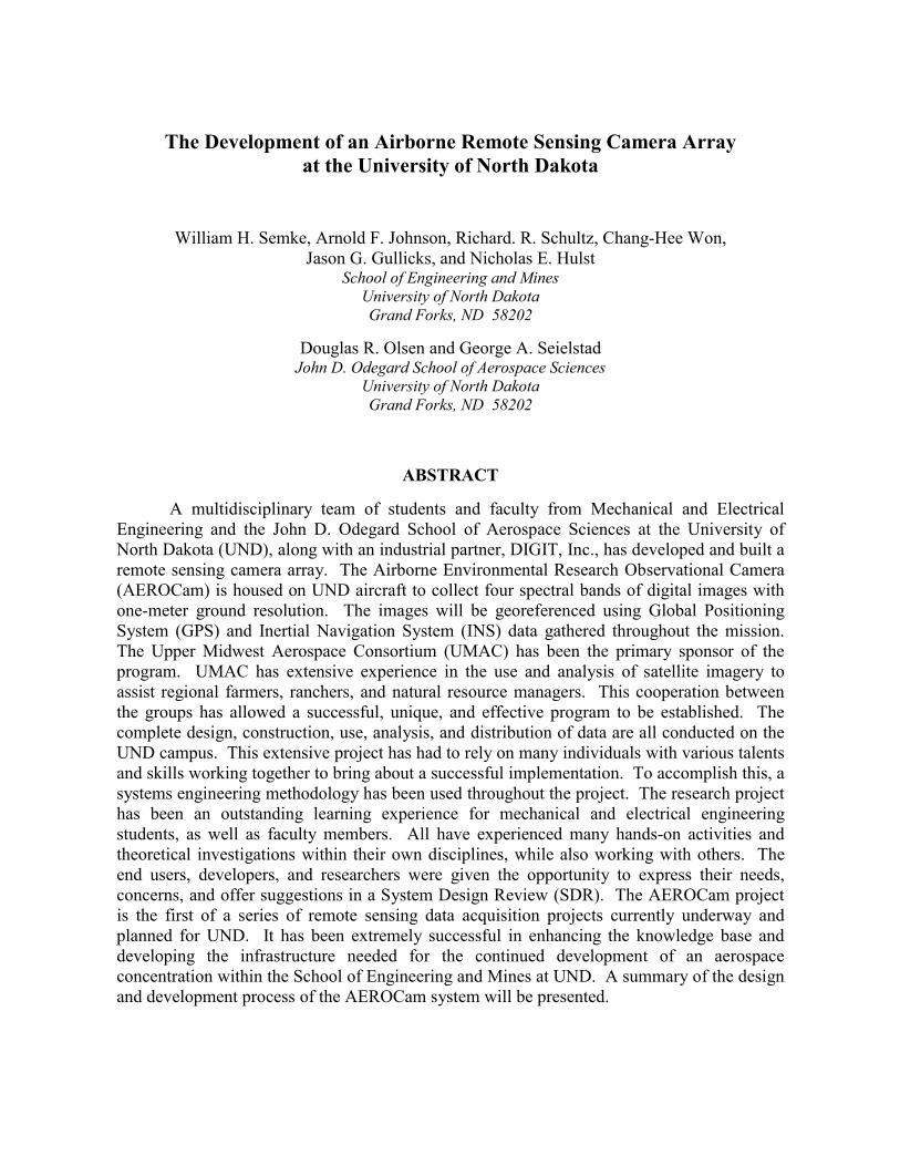
The AEROCam system is flown in UND Piper Arrow aircraft, as seen in Fig. 1. Using sound engineering practice and meeting Federal Aviation Agency (FAA) requirements, all systems are designed to provide the maximum amount of safety for the aircraft and operator. The current system is built to adhere or exceed all FAA regulations regarding the modification of UND Aerospace aircraft, which consists of a fleet of over 100 aircraft. The use of FAA Designated Engineering Representatives (DER) for restricted certification was utilized to “streamline” the FAA certification process. Complete documentation of the design including computer aided drafting (CAD) drawings, analytical calculations, finite element models and simulations, and test results is required. This is to ensure adequate weight and balance for the aircraft along with the ability of all components to survive a 9-g crash without detachment. These efforts will be in cooperation and assistance from the UND Aerospace Director of Maintenance and Quality Assurance Manager.
(a) (b)
Fig. 1. The AEROCam system (a) on its way out for take-off and (b) installed in the hanger.
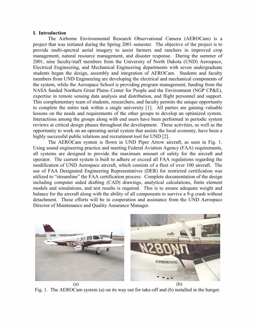
The primary objective for the project is to provide useful information on crop management for regional farmers and ranchers in a timely manner. To achieve this several objectives had to be met. The first is a high spatial resolution of under 5-meters to provide users sufficiently detailed data to be used in contemporary farming practices. The second is the selection of the appropriate spectral bands to be used, including the visible red, green, and blue along with near-infrared. The third is flexible data acquisition time so that critical periods during the crop’s maturation can be monitored. Lastly, the processed data must be made available to the end users in a timely manner. This means the data will be available within 24 hours from the time the raw images are acquired. By adhering to these objectives a system that is not available by any other current means will be made accessible. An example of processed data is shown in Fig. 2(a). The image illustrates an example of a Normalized Difference Vegetative Index (NDVI) map that is commonly used in agriculture remote sensing. Mapping such as this can then delineate zones within fields, allowing the application rates to be varied as needed, as seen in Fig. 2(b).
(a) (b)
Fig. 2. (a) An example of an NDVI image collected by an aerial remote sensing device. (b) An example of a contour map indicating application rates.
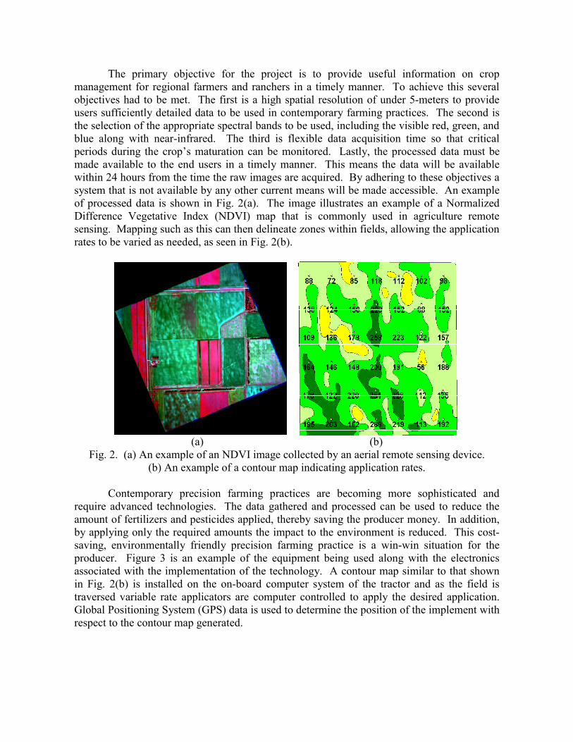
Contemporary precision farming practices are becoming more sophisticated and require advanced technologies. The data gathered and processed can be used to reduce the amount of fertilizers and pesticides applied, thereby saving the producer money. In addition, by applying only the required amounts the impact to the environment is reduced. This cost-saving, environmentally friendly precision farming practice is a win-win situation for the producer. Figure 3 is an example of the equipment being used along with the electronics associated with the implementation of the technology. A contour map similar to that shown in Fig. 2(b) is installed on the on-board computer system of the tractor and as the field is traversed variable rate applicators are computer controlled to apply the desired application. Global Positioning System (GPS) data is used to determine the position of the implement with respect to the contour map generated.
(a) (b)
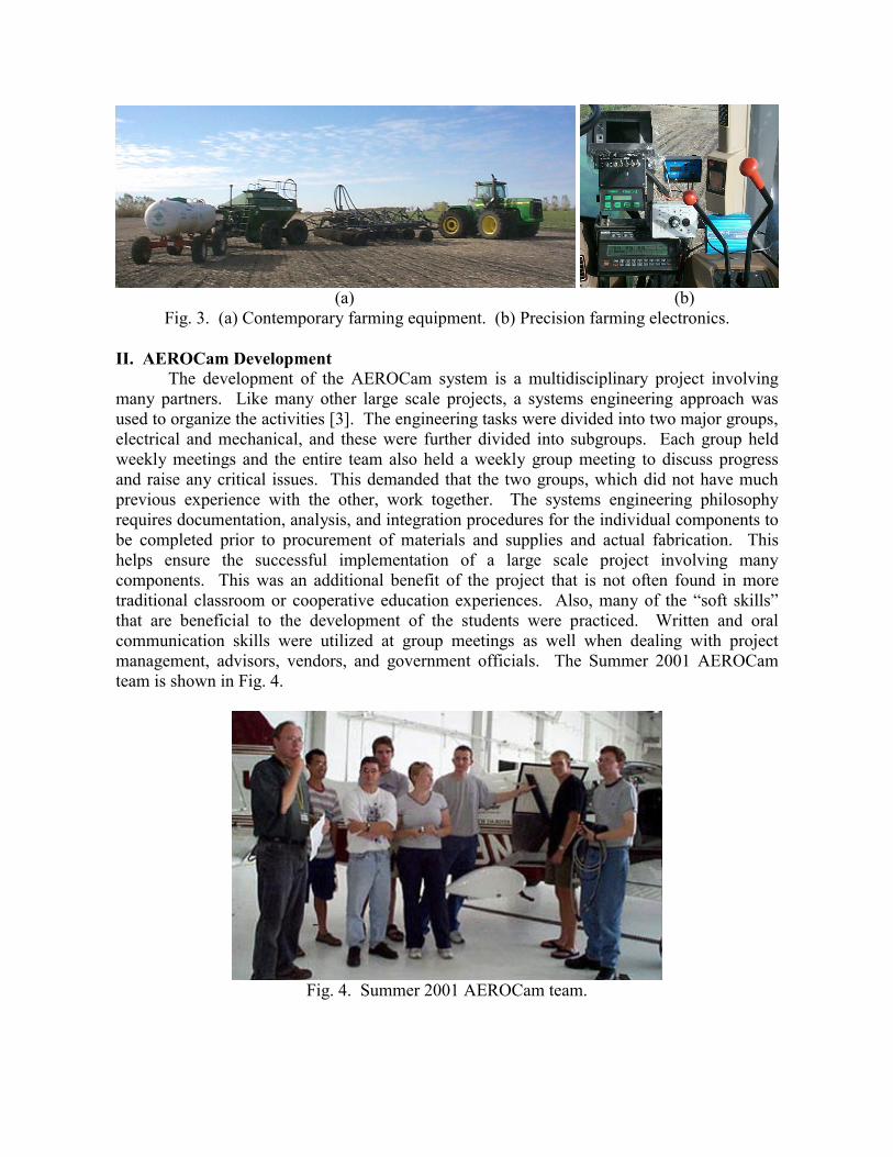
Fig. 3. (a) Contemporary farming equipment. (b) Precision farming electronics. II. AEROCam Development The development of the AEROCam system is a multidisciplinary project involving many partners. Like many other large scale projects, a systems engineering approach was used to organize the activities [3]. The engineering tasks were divided into two major groups, electrical and mechanical, and these were further divided into subgroups. Each group held weekly meetings and the entire team also held a weekly group meeting to discuss progress and raise any critical issues. This demanded that the two groups, which did not have much previous experience with the other, work together. The systems engineering philosophy requires documentation, analysis, and integration procedures for the individual components to be completed prior to procurement of materials and supplies and actual fabrication. This helps ensure the successful implementation of a large scale project involving many components. This was an additional benefit of the project that is not often found in more traditional classroom or cooperative education experiences. Also, many of the “soft skills” that are beneficial to the development of the students were practiced. Written and oral communication skills were utilized at group meetings as well when dealing with project management, advisors, vendors, and government officials. The Summer 2001 AEROCam team is shown in Fig. 4.
Fig. 4. Summer 2001 AEROCam team.
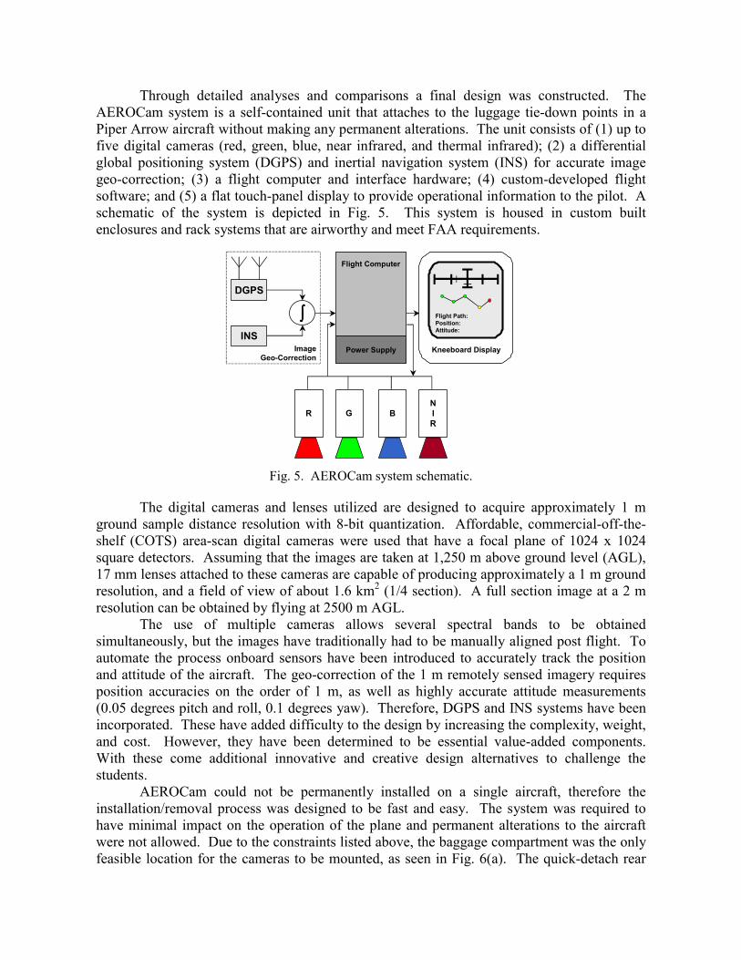
Through detailed analyses and comparisons a final design was constructed. The AEROCam system is a self-contained unit that attaches to the luggage tie-down points in a Piper Arrow aircraft without making any permanent alterations. The unit consists of (1) up to five digital cameras (red, green, blue, near infrared, and thermal infrared); (2) a differential global positioning system (DGPS) and inertial navigation system (INS) for accurate image geo-correction; (3) a flight computer and interface hardware; (4) custom-developed flight software; and (5) a flat touch-panel display to provide operational information to the pilot. A schematic of the system is depicted in Fig. 5. This system is housed in custom built enclosures and rack systems that are airworthy and meet FAA requirements.
NIR
R G B
DGPS
INS
∫∫∫∫
ImageGeo-Correction
Flight Computer
Power Supply Kneeboard Display
Flight Path:Position:Attitude:
Fig. 5. AEROCam system schematic.
The digital cameras and lenses utilized are designed to acquire approximately 1 m
ground sample distance resolution with 8-bit quantization. Affordable, commercial-off-the-shelf (COTS) area-scan digital cameras were used that have a focal plane of 1024 x 1024 square detectors. Assuming that the images are taken at 1,250 m above ground level (AGL), 17 mm lenses attached to these cameras are capable of producing approximately a 1 m ground resolution, and a field of view of about 1.6 km2 (1/4 section). A full section image at a 2 m resolution can be obtained by flying at 2500 m AGL.
The use of multiple cameras allows several spectral bands to be obtained simultaneously, but the images have traditionally had to be manually aligned post flight. To automate the process onboard sensors have been introduced to accurately track the position and attitude of the aircraft. The geo-correction of the 1 m remotely sensed imagery requires position accuracies on the order of 1 m, as well as highly accurate attitude measurements (0.05 degrees pitch and roll, 0.1 degrees yaw). Therefore, DGPS and INS systems have been incorporated. These have added difficulty to the design by increasing the complexity, weight, and cost. However, they have been determined to be essential value-added components. With these come additional innovative and creative design alternatives to challenge the students.
AEROCam could not be permanently installed on a single aircraft, therefore the installation/removal process was designed to be fast and easy. The system was required to have minimal impact on the operation of the plane and permanent alterations to the aircraft were not allowed. Due to the constraints listed above, the baggage compartment was the only feasible location for the cameras to be mounted, as seen in Fig. 6(a). The quick-detach rear
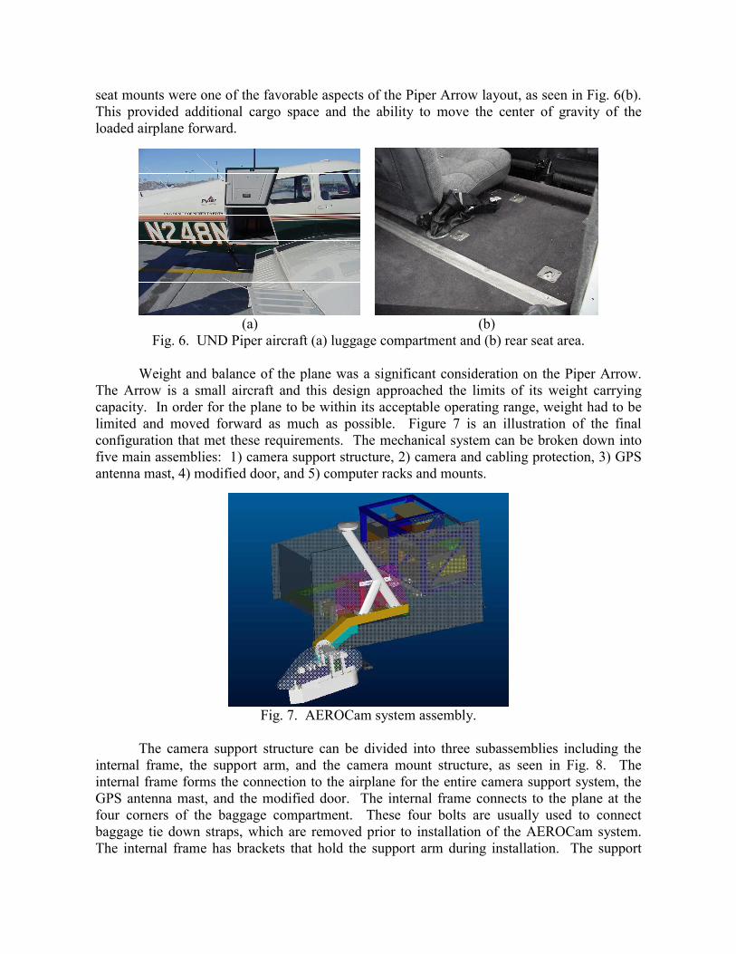
seat mounts were one of the favorable aspects of the Piper Arrow layout, as seen in Fig. 6(b). This provided additional cargo space and the ability to move the center of gravity of the loaded airplane forward.
(a) (b)
Fig. 6. UND Piper aircraft (a) luggage compartment and (b) rear seat area.
Weight and balance of the plane was a significant consideration on the Piper Arrow. The Arrow is a small aircraft and this design approached the limits of its weight carrying capacity. In order for the plane to be within its acceptable operating range, weight had to be limited and moved forward as much as possible. Figure 7 is an illustration of the final configuration that met these requirements. The mechanical system can be broken down into five main assemblies: 1) camera support structure, 2) camera and cabling protection, 3) GPS antenna mast, 4) modified door, and 5) computer racks and mounts.
Fig. 7. AEROCam system assembly.
The camera support structure can be divided into three subassemblies including the
internal frame, the support arm, and the camera mount structure, as seen in Fig. 8. The internal frame forms the connection to the airplane for the entire camera support system, the GPS antenna mast, and the modified door. The internal frame connects to the plane at the four corners of the baggage compartment. These four bolts are usually used to connect baggage tie down straps, which are removed prior to installation of the AEROCam system. The internal frame has brackets that hold the support arm during installation. The support
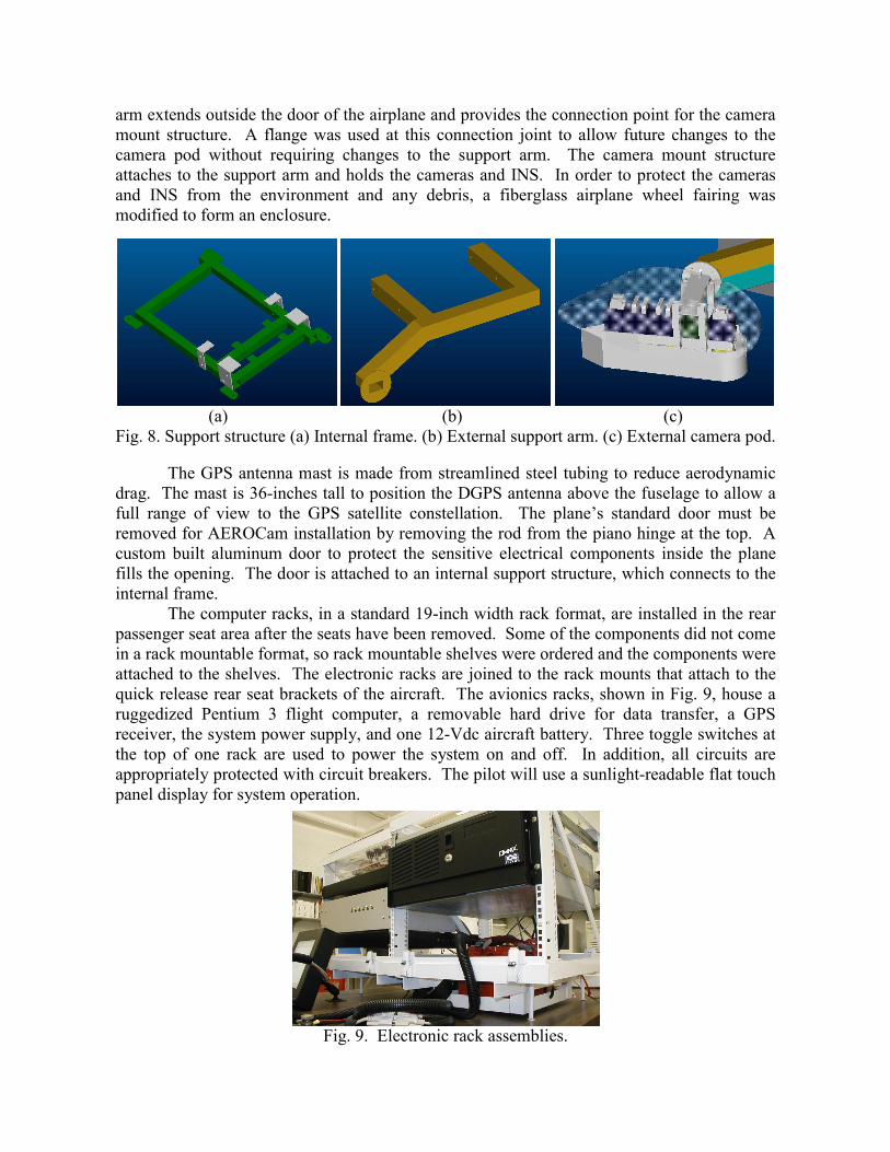
arm extends outside the door of the airplane and provides the connection point for the camera mount structure. A flange was used at this connection joint to allow future changes to the camera pod without requiring changes to the support arm. The camera mount structure attaches to the support arm and holds the cameras and INS. In order to protect the cameras and INS from the environment and any debris, a fiberglass airplane wheel fairing was modified to form an enclosure.
(a) (b) (c)
Fig. 8. Support structure (a) Internal frame. (b) External support arm. (c) External camera pod.
The GPS antenna mast is made from streamlined steel tubing to reduce aerodynamic drag. The mast is 36-inches tall to position the DGPS antenna above the fuselage to allow a full range of view to the GPS satellite constellation. The plane’s standard door must be removed for AEROCam installation by removing the rod from the piano hinge at the top. A custom built aluminum door to protect the sensitive electrical components inside the plane fills the opening. The door is attached to an internal support structure, which connects to the internal frame.
The computer racks, in a standard 19-inch width rack format, are installed in the rear passenger seat area after the seats have been removed. Some of the components did not come in a rack mountable format, so rack mountable shelves were ordered and the components were attached to the shelves. The electronic racks are joined to the rack mounts that attach to the quick release rear seat brackets of the aircraft. The avionics racks, shown in Fig. 9, house a ruggedized Pentium 3 flight computer, a removable hard drive for data transfer, a GPS receiver, the system power supply, and one 12-Vdc aircraft battery. Three toggle switches at the top of one rack are used to power the system on and off. In addition, all circuits are appropriately protected with circuit breakers. The pilot will use a sunlight-readable flat touch panel display for system operation.
Fig. 9. Electronic rack assemblies.
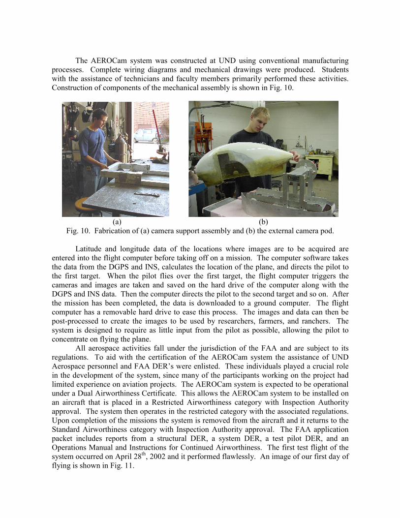
The AEROCam system was constructed at UND using conventional manufacturing processes. Complete wiring diagrams and mechanical drawings were produced. Students with the assistance of technicians and faculty members primarily performed these activities. Construction of components of the mechanical assembly is shown in Fig. 10.
(a) (b)
Fig. 10. Fabrication of (a) camera support assembly and (b) the external camera pod.
Latitude and longitude data of the locations where images are to be acquired are entered into the flight computer before taking off on a mission. The computer software takes the data from the DGPS and INS, calculates the location of the plane, and directs the pilot to the first target. When the pilot flies over the first target, the flight computer triggers the cameras and images are taken and saved on the hard drive of the computer along with the DGPS and INS data. Then the computer directs the pilot to the second target and so on. After the mission has been completed, the data is downloaded to a ground computer. The flight computer has a removable hard drive to ease this process. The images and data can then be post-processed to create the images to be used by researchers, farmers, and ranchers. The system is designed to require as little input from the pilot as possible, allowing the pilot to concentrate on flying the plane. All aerospace activities fall under the jurisdiction of the FAA and are subject to its regulations. To aid with the certification of the AEROCam system the assistance of UND Aerospace personnel and FAA DER’s were enlisted. These individuals played a crucial role in the development of the system, since many of the participants working on the project had limited experience on aviation projects. The AEROCam system is expected to be operational under a Dual Airworthiness Certificate. This allows the AEROCam system to be installed on an aircraft that is placed in a Restricted Airworthiness category with Inspection Authority approval. The system then operates in the restricted category with the associated regulations. Upon completion of the missions the system is removed from the aircraft and it returns to the Standard Airworthiness category with Inspection Authority approval. The FAA application packet includes reports from a structural DER, a system DER, a test pilot DER, and an Operations Manual and Instructions for Continued Airworthiness. The first test flight of the system occurred on April 28th, 2002 and it performed flawlessly. An image of our first day of flying is shown in Fig. 11.
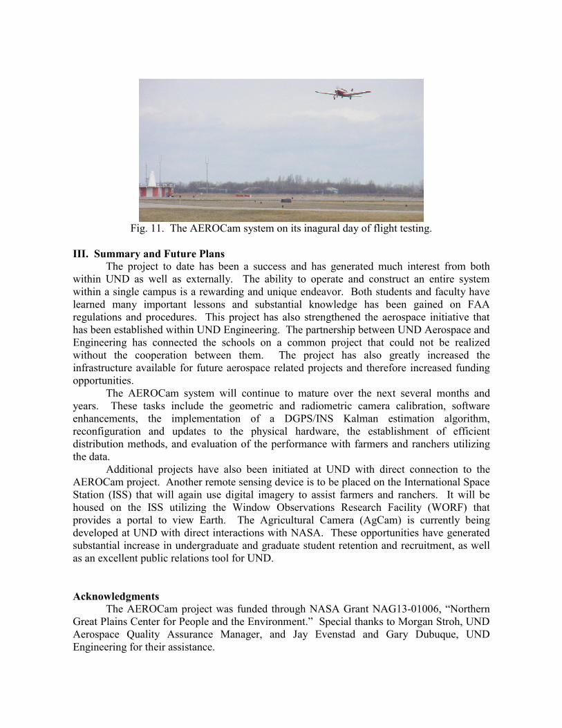
Fig. 11. The AEROCam system on its inagural day of flight testing.
III. Summary and Future Plans The project to date has been a success and has generated much interest from both within UND as well as externally. The ability to operate and construct an entire system within a single campus is a rewarding and unique endeavor. Both students and faculty have learned many important lessons and substantial knowledge has been gained on FAA regulations and procedures. This project has also strengthened the aerospace initiative that has been established within UND Engineering. The partnership between UND Aerospace and Engineering has connected the schools on a common project that could not be realized without the cooperation between them. The project has also greatly increased the infrastructure available for future aerospace related projects and therefore increased funding opportunities. The AEROCam system will continue to mature over the next several months and years. These tasks include the geometric and radiometric camera calibration, software enhancements, the implementation of a DGPS/INS Kalman estimation algorithm, reconfiguration and updates to the physical hardware, the establishment of efficient distribution methods, and evaluation of the performance with farmers and ranchers utilizing the data. Additional projects have also been initiated at UND with direct connection to the AEROCam project. Another remote sensing device is to be placed on the International Space Station (ISS) that will again use digital imagery to assist farmers and ranchers. It will be housed on the ISS utilizing the Window Observations Research Facility (WORF) that provides a portal to view Earth. The Agricultural Camera (AgCam) is currently being developed at UND with direct interactions with NASA. These opportunities have generated substantial increase in undergraduate and graduate student retention and recruitment, as well as an excellent public relations tool for UND. Acknowledgments
The AEROCam project was funded through NASA Grant NAG13-01006, “Northern Great Plains Center for People and the Environment.” Special thanks to Morgan Stroh, UND Aerospace Quality Assurance Manager, and Jay Evenstad and Gary Dubuque, UND Engineering for their assistance.
References [1] Hulst, N., Gullicks, J., Johnson, J., Lauinger, G., Larson, D., Lemcke, S., Johnson, A.,
Schultz, R., Semke, W., Won, C., Geisinger, B., Olsen, D., Osburnsen, P., Seielstad, G., and Wivell, C., “The Airborne Environmental Research Observational Camera (AEROCam): A Multispectral Digital Photography System for Remote Sensing,” Proc. of the National Conference on Undergraduate Research 2002, Whitewater, WI, April 25-27, 2002.
[2] Won, C., Sale, D., Schultz, R., Johnson, A., and Semke, W., “Spacecraft Systems
Engineering – The Initiation of a Multidisciplinary Design Project at the University of North Dakota,” Proc. 2001 American Society for Engineering Education Annual Conference & Exposition, Electrical and Computer Engineering Division, Albuquerque, NM, June 24-27, 2001.
[3] Wertz, J., and Larson, W. (editors), Space Mission Analysis and Design, Third Edition,
Space Technology Library, Torrance, CA, 1999.