Embed Size (px)
Citation preview
White Paper
Copyright © 2016 ARM Limited or its affiliates. All rights reserved. Page 1 of 19
The DSP capabilities of ARM® Cortex®-M4 and Cortex-M7 Processors
DSP feature set and benchmarks
Thomas Lorenser
November 2016
White Paper
Copyright © 2016 ARM Limited or its affiliates. All rights reserved. Page 2 of 19
Table of Contents
Introduction ................................................................................................................................................ 3
Digital Signal Controllers combine MCU and DSP capabilities ........................................................................ 3
Cortex-M4/Cortex-M7 ISA supporting efficient DSP operations .................................................................... 4
Data types ................................................................................................................................................... 5
Instruction set for arithmetic, SIMD and floating-point .................................................................................. 6
DSP techniques used on Cortex-M4 and Cortex-M7 .................................................................................... 8
Fast Fourier Transforms (FFT) ................................................................................................................... 10
FIR Filter ................................................................................................................................................... 13
Understanding the performance differences ................................................................................................ 14
Conclusion ................................................................................................................................................ 14
Appendix .................................................................................................................................................. 15 Arithmetic instructions ......................................................................................................................................... 15 SIMD instructions ................................................................................................................................................. 16 Floating-point instructions ..................................................................................................................................... 17
Trademarks ............................................................................................................................................... 19
White Paper
Copyright © 2016 ARM Limited or its affiliates. All rights reserved. Page 3 of 19
Introduction As we see the spectacular growth in the number of autonomous, intelligent, and connected devices (i.e. smart embedded, the Internet of Things, or IoT), which are required to operate in a low-power environment, manufacturers are increasingly turning to place the ARM Cortex-M4 and Cortex-M7 processors at the heart of these devices. Such applications previously used a simple Microcontroller (MCU) based on Cortex-M0 or Cortex-M3 together with a separate proprietary, dedicated Digital Signal Processor (DSP). More and more OEMs are switching to a single, high-performance, low power MCU with DSP extensions, such as Cortex-M4 or Cortex-M7, to replace the two processor design. This has a number of advantages for OEMs. It can save significantly on the BOM costs of their products, by replacing two processors with one, and a reduction in system-level complexity by removing the need for shared memory, MCU and DSP communication, complex multiprocessor bus architectures and other custom “glue” logic between the MCU and DSP. It also has the advantages of reducing software development costs, as the entire project can be supported using a single compiler/debugger/IDE, and benefits from being programmable in a high-level programming language such as C or C++, rather than the handcrafted assembler often used for a proprietary DSP. ARM’s Digital Signal Controllers, Cortex-M4 and Cortex-M7, address the need for high-performance generic code processing as well as digital signal processing applications. The key feature of the Cortex-M4 and Cortex-M7 processors is the addition of DSP extensions to the Thumb instruction set, as defined in ARM’s architecture ARMv7-M and the optional floating-point unit (FPU). These instructions are designed to help improve the performance of numerical algorithms and provide the opportunity to perform signal processing operations directly on the Cortex-M4 and Cortex-M7. This whitepaper describes the DSP features of ARM’s Digital Signal Controllers, Cortex-M4 and Cortex-M7, explains how they are employed in the CMSIS DSP Library (a free-of-charge library of DSP functions optimized for the Cortex-M4 and Cortex-M7 processors), and presents some benchmark results on well-known DSP algorithms.
Digital Signal Controllers combine MCU and DSP capabilities MCUs are traditionally designed to offer general-purpose computation and efficient control flow, whilst integrating with a variety of low power memory types (such as Flash and SRAM), and providing very rapid reaction to external interrupt sources. Such an MCU may include a wide variety of peripherals built-in such as USB, Ethernet, Analog-to-Digital convertors, UARTs, SPI interfaces, timers and so on. As MCUs can be used in a wide variety of applications, and sell in the billions of units, they are also supported by a large number of RTOSes, compilers, debuggers, IDEs and middleware.
DSPs, on the other hand, are traditionally designed with multiple memory buses, allowing computation and memory accesses to be performed in parallel. This supports the rapid throughput of data, with typical operations such as multiplication and accumulate (commonly known as multiply-accumulate, or MAC) to be performed efficiently on that data with minimal overhead. This is further helped by providing such features as:
• Zero overhead loops • Single-cycle MACs • Circular memory addressing • Accumulators with guard bits • Fractional and saturating arithmetic
These features allow a DSP to execute numerically-intensive algorithms in real time, which is why they were originally deployed in military radar and sonar processing, and later started to be used in a wide variety of consumer devices that demanded efficient signal processing, such as audio, voice recognition and image enhancement.
White Paper
Copyright © 2016 ARM Limited or its affiliates. All rights reserved. Page 4 of 19
ARM’s Cortex-M4 and Cortex-M7 processors are Digital Signal Controllers (DSC), providing a blend of traditional MCU and DSP functionality in a single instruction set working in the same bank of general-purpose 32-bit registers. The important feature to note is that the DSP functionality is built right into the ISA, rather than being implemented via a co-processor interface. Both of these processors also have an optional floating-point unit that fully supports the IEEE-754 standard, with the Cortex-M4 offering single-precision floating point support and the Cortex-M7 supporting single-precision and double-precision floating-point. Hence Cortex-M4 and Cortex-M7 offer efficient processing of signal processing algorithms.
Cortex-M4/Cortex-M7 ISA supporting efficient DSP operations This section provides a brief overview of the instructions implemented by Cortex-M4 and Cortex-M7, which accelerate DSP algorithms. The goal is not to include all such instructions (which can be found in the Generic User Guides for Cortex-M4 at https://developer.arm.com/docs/dui0553/b and Cortex-M7 at https://developer.arm.com/docs/dui0646/a), but to highlight which instructions are most often used in practice.
While Cortex-M4 and Cortex-M7 can be used in DSP applications for both fixed-point and floating-point operations, the DSP extension is optimized for fixed-point applications. Floating-point operations are accelerated using the optional floating-point unit.
As the Cortex-M4 and Cortex-M7 processor have instructions that are carefully designed to support high-level languages, C compilers are able to choose the most efficient instructions without additional help. In some cases, we use idioms - sections of C code which are recognized by a compiler as mapping directly to underlying assembly instructions. Finally, in some cases – particularly with Single Instruction Multiple Data (SIMD) instructions - the compilers are not always able to efficiently utilize the instruction set when compiling C code. In this case, we have to provide the compiler with explicit guidance using intrinsics.
General purpose and special registers
The Cortex-M4 and Cortex-M7 processors have a core register bank consisting of 16 32-bit registers. The lower 13 registers, R0-R12, are general purpose and can hold intermediate variables, pointers, function arguments, and return results. The upper 3 registers are reserved by the architecture and given a particular role.
R0 to R12 – General purpose R13 – Stack pointer [reserved] R14 – Link register [reserved] R15 – Program counter [reserved]
When compiling code, the compiler will try to allocate the available registers efficiently to local variables and function arguments, but if it runs out of general-purpose registers, it will need to spill intermediate values onto the stack, causing a slowdown in performance. This can be mitigated for most DSP functions using the CMSIS DSP library (described on page 11), which has been carefully designed to take care of register usage.
Registers using the optional floating-point unit
The optional floating-point unit (FPU) on the Cortex-M4 and Cortex-M7 has its own bank of registers consisting of 32 32-bit registers that can be accessed as single-precision FPU registers (labelled S0 to S31), or accessed as a pair of double-precision registers (labelled as d0 to d15). The integer registers R0 to R12 are still available to hold integer variables, giving a total of 45 registers that can be used by the C compiler. It is expected that C compilers only use R0 to R12 for non-floating point data processing. Typically floating-point operations use more processor cycles than their
White Paper
Copyright © 2016 ARM Limited or its affiliates. All rights reserved. Page 5 of 19
integer equivalents, but are much faster than emulating floating point via integer operations. Sometimes a smart compiler is able to use the floating-point registers as data storage to accelerate algorithms that are running out of integer registers, but this can come as a cost of impact to interrupt latency. Additionally, compilers can natively create code by leveraging the float instructions without using intrinsics.
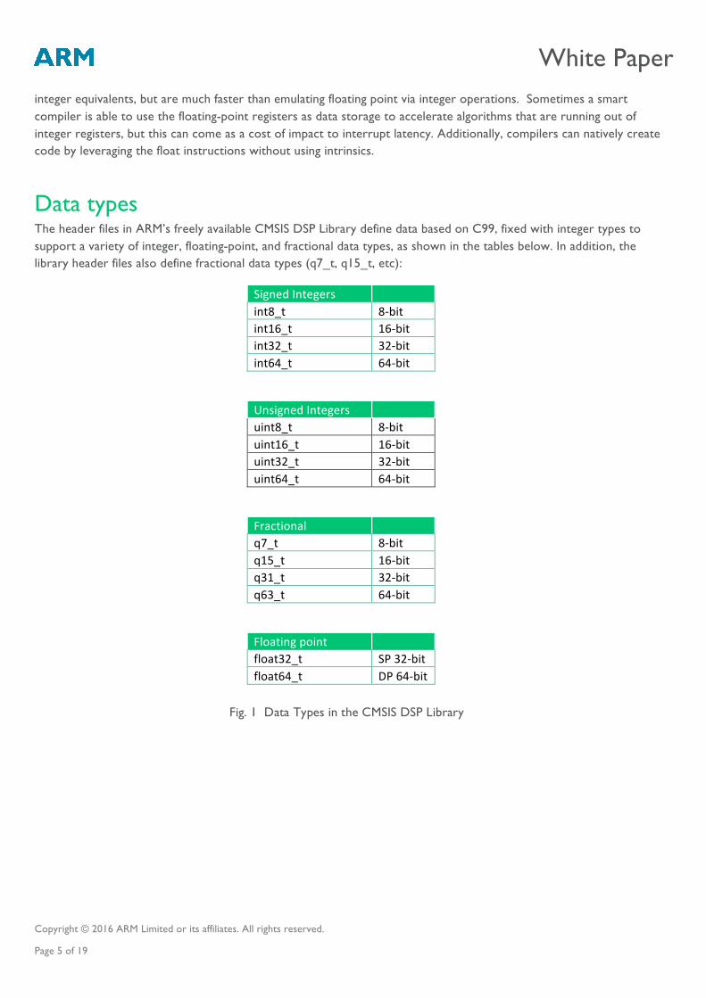
Data types The header files in ARM’s freely available CMSIS DSP Library define data based on C99, fixed with integer types to support a variety of integer, floating-point, and fractional data types, as shown in the tables below. In addition, the library header files also define fractional data types (q7_t, q15_t, etc):
Signed Integers int8_t 8-‐bit int16_t 16-‐bit int32_t 32-‐bit int64_t 64-‐bit
Unsigned Integers uint8_t 8-‐bit uint16_t 16-‐bit uint32_t 32-‐bit uint64_t 64-‐bit
Fractional q7_t 8-‐bit q15_t 16-‐bit q31_t 32-‐bit q63_t 64-‐bit
Floating point float32_t SP 32-‐bit float64_t DP 64-‐bit
Fig. 1 Data Types in the CMSIS DSP Library
White Paper
Copyright © 2016 ARM Limited or its affiliates. All rights reserved. Page 6 of 19
Instruction set for arithmetic, SIMD and floating-point Arithmetic instructions
There are a number of arithmetic instructions for integer and fractional datatypes supported by the Cortex-M4 and Cortex-M7 which are most frequently used in DSP algorithms.
The instructions vary on how they are emitted by a C compiler. In some cases, the compiler determines the correct instruction to use based on standard C code. For example, fractional addition is performed using:
z = x + y;
In other cases, the compiler recognizes a number of standard “idioms”, which are C expressions commonly used in DSP algorithms, and maps them to the appropriate instruction. For example, to swap bytes 0 and 1, and 2 and 3 of a 32-bit word, use the idiom
(((x&0xff)<<8)¦((x&0xff00)>>8)¦((x&0xff000000)>>8)¦((x&0x00ff0000)<<8));
The compiler recognizes this and maps it to a single REV16 instruction.
And finally, in some cases there is no C construct that maps to the underlying instruction and the instruction can only be invoked via an intrinsic. For example, to do a saturating 32-bit addition use
z = __QADD(x, y);
Check your compiler documentation to see which idioms are supported and how they map to Cortex-M instructions.
The appendix gives a more detailed description of some of the arithmetic instructions provided in the Cortex-M4 and Cortex-M7 processors that are used to optimize well-known DSP algorithms. The instructions use either signed or unsigned integer format, the data representation using fractional dataypes may require some additional bit shift operations. Please visit the Devices Generic User Guide for Cortex-M4 and Cortex-M7 for a full list of arithmetic instructions.
All of the instructions are single-cycle on Cortex-M4 (except hardware divide), and may well be dual-issued in parallel with other instructions on Cortex-M7, thus further reducing the cycle count for DSP inner loops and other performance critical code.
SIMD instructions
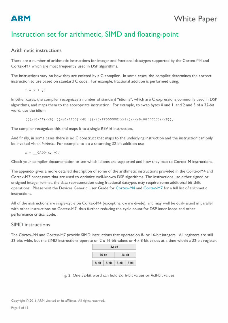
The Cortex-M4 and Cortex-M7 provide SIMD instructions that operate on 8- or 16-bit integers. All registers are still 32-bits wide, but the SIMD instructions operate on 2 x 16-bit values or 4 x 8-bit values at a time within a 32-bit register.
8-bit 8-bit 8-bit 8-bit
16-bit 16-bit
32-bit
Fig. 2 One 32-bit word can hold 2x16-bit values or 4x8-bit values
White Paper
Copyright © 2016 ARM Limited or its affiliates. All rights reserved. Page 7 of 19
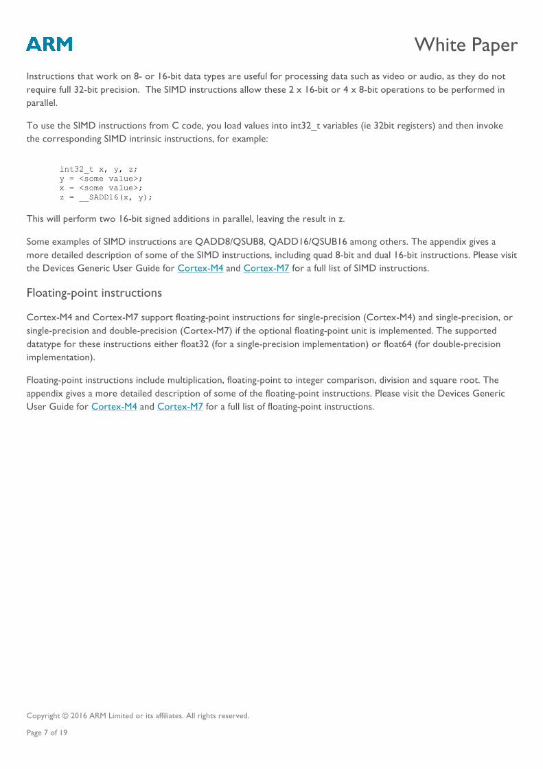
Instructions that work on 8- or 16-bit data types are useful for processing data such as video or audio, as they do not require full 32-bit precision. The SIMD instructions allow these 2 x 16-bit or 4 x 8-bit operations to be performed in parallel.
To use the SIMD instructions from C code, you load values into int32_t variables (ie 32bit registers) and then invoke the corresponding SIMD intrinsic instructions, for example:
int32_t x, y, z; y = <some value>; x = <some value>; z = __SADD16(x, y);
This will perform two 16-bit signed additions in parallel, leaving the result in z.
Some examples of SIMD instructions are QADD8/QSUB8, QADD16/QSUB16 among others. The appendix gives a more detailed description of some of the SIMD instructions, including quad 8-bit and dual 16-bit instructions. Please visit the Devices Generic User Guide for Cortex-M4 and Cortex-M7 for a full list of SIMD instructions.
Floating-point instructions
Cortex-M4 and Cortex-M7 support floating-point instructions for single-precision (Cortex-M4) and single-precision, or single-precision and double-precision (Cortex-M7) if the optional floating-point unit is implemented. The supported datatype for these instructions either float32 (for a single-precision implementation) or float64 (for double-precision implementation).
Floating-point instructions include multiplication, floating-point to integer comparison, division and square root. The appendix gives a more detailed description of some of the floating-point instructions. Please visit the Devices Generic User Guide for Cortex-M4 and Cortex-M7 for a full list of floating-point instructions.
White Paper
Copyright © 2016 ARM Limited or its affiliates. All rights reserved. Page 8 of 19
CMSIS DSP library
The CMSIS-DSP library is a suite of common signal processing and mathematical functions that have been optimized for the Cortex-M4 and Cortex-M7 processors. The library is freely available as part of the CMSIS release from ARM and includes all source code. The functions in the library are divided into several categories:
1. Basic math functions 2. Fast math functions 3. Complex math functions 4. Filters 5. Matrix functions 6. Transforms 7. Motor control functions 8. Statistical functions 9. Support functions 10. Interpolation functions
The library has separate functions for operating on 8-bit integers, 16-bit integers, 32-bit integers, and 32-bit floating-point values.
The library has been optimized to take advantage of the DSP extensions found in the Cortex-M4 and Cortex-M7 processors. The CMSIS DSP Library can also be used on the Cortex-M3 processor although it doesn’t provide the additional extensions to accelerate DSP algorithms. In the results presented later in this paper, we show the significant performance difference between the same DSP algorithms when run on the Cortex-M3, Cortex-M4 and Cortex-M7 processors.
DSP techniques used on Cortex-M4 and Cortex-M7 Some features of a traditional DSP are not present on the Cortex-M4 and Cortex-M7 processors, so in the CMSIS DSP Library we use programming techniques to best use the available features of the Cortex-M architecture.
One example of this is the use of circular addressing when processing buffers of input and output data. Most DSPs have a memory architecture which automatically wraps around at the end of a buffer. The Cortex-M4 and Cortex-M7 processors address memory as a flat linear address space, so in the CMSIS DSP library we use a FIFO and shift the data in the FIFO once per block of data. This reduces the data movement overhead by a factor of the input sample size. It also means that we do not incur the overhead of checking the index value every time round an inner processing loop.
White Paper
Copyright © 2016 ARM Limited or its affiliates. All rights reserved. Page 9 of 19
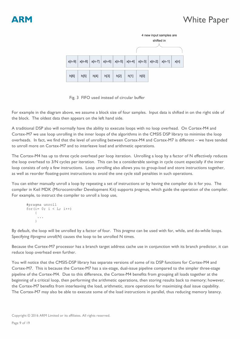
h[0]h[1]h[2]h[3]h[4]h[5]h[6]
x[n]x[n-1]x[n-2]x[n-3]x[n-4]x[n-5]x[n-6]x[n-7]x[n-8]x[n-9]
4 new input samples are shifted in
For example in the diagram above, we assume a block size of four samples. Input data is shifted in on the right side of the block. The oldest data then appears on the left hand side.
A traditional DSP also will normally have the ability to execute loops with no loop overhead. On Cortex-M4 and Cortex-M7 we use loop unrolling in the inner loops of the algorithms in the CMSIS DSP library to minimise the loop overheads. In fact, we find that the level of unrolling between Cortex-M4 and Cortex-M7 is different – we have tended to unroll more on Cortex-M7 and to interleave load and arithmetic operations.
The Cortex-M4 has up to three cycle overhead per loop iteration. Unrolling a loop by a factor of N effectively reduces the loop overhead to 3/N cycles per iteration. This can be a considerable savings in cycle count especially if the inner loop consists of only a few instructions. Loop unrolling also allows you to group-load and store instructions together, as well as reorder floating-point instructions to avoid the one cycle stall penalties in such operations.
You can either manually unroll a loop by repeating a set of instructions or by having the compiler do it for you. The compiler in Keil MDK (Microcontroller Development Kit) supports pragmas, which guide the operation of the compiler. For example, to instruct the compiler to unroll a loop use,
#pragma unroll for(i= 0; i < L; i++) { ... }
By default, the loop will be unrolled by a factor of four. This pragma can be used with for, while, and do-while loops. Specifying #pragma unroll(N) causes the loop to be unrolled N times.
Because the Cortex-M7 processor has a branch target address cache use in conjunction with its branch predictor, it can reduce loop overhead even further.
You will notice that the CMSIS-DSP library has separate versions of some of its DSP functions for Cortex-M4 and Cortex-M7. This is because the Cortex-M7 has a six-stage, dual-issue pipeline compared to the simpler three-stage pipeline of the Cortex-M4. Due to this difference, the Cortex-M4 benefits from grouping all loads together at the beginning of a critical loop, then performing the arithmetic operations, then storing results back to memory; however, the Cortex-M7 benefits from interleaving the load, arithmetic, store operations for maximizing dual issue capability. The Cortex-M7 may also be able to execute some of the load instructions in parallel, thus reducing memory latency.
Fig. 3 FIFO used instead of circular buffer
White Paper
Copyright © 2016 ARM Limited or its affiliates. All rights reserved. Page 10 of 19
Fast Fourier Transforms (FFT) Within the CMSIS-DSP Library, there are a number of optimised functions for computing the FFT of an input sample using a variety of data types such as Q7, Q15, Q31, F32.
Fundamentally, the FFT is a fast way of calculating the discrete Fourier transform of an input stream of length N, given by the equation:
𝑋 𝑘 = 𝑥 𝑛 𝑊!!"
!!!
!!!
, 𝑘 = 0, 1, 2,… ,𝑁 − 1
where 𝑊!! is a complex value representing the 𝑘!! root of unity:
𝑊!! = 𝑒!!!!"/! = cos 2𝜋𝑘/𝑁 − 𝑗 sin 2𝜋𝑘/𝑁 .
The CMSIS DSP library uses a variant of a decimation-in-frequency algorithm, which is implemented by a series of “butterfly” calculations, where each butterfly includes a complex addition, subtraction and multiplication – all of which can be performed in place in memory. The result of all such algorithms is that the output becomes bit-reversed, and the CMSIS DSP Library functions provide an option for the output to be reordered back into sequential order.
Implementations of FFT algorithms normally use either radix-2 or radix-4 techniques to operate on either two or four complex values at a time, depending on the size of the input sample. In the latest version of the CMSIS DSP Library, the FFT functions will automatically choose the appropriate technique given the input sample size, without the user being expected to make that choice.
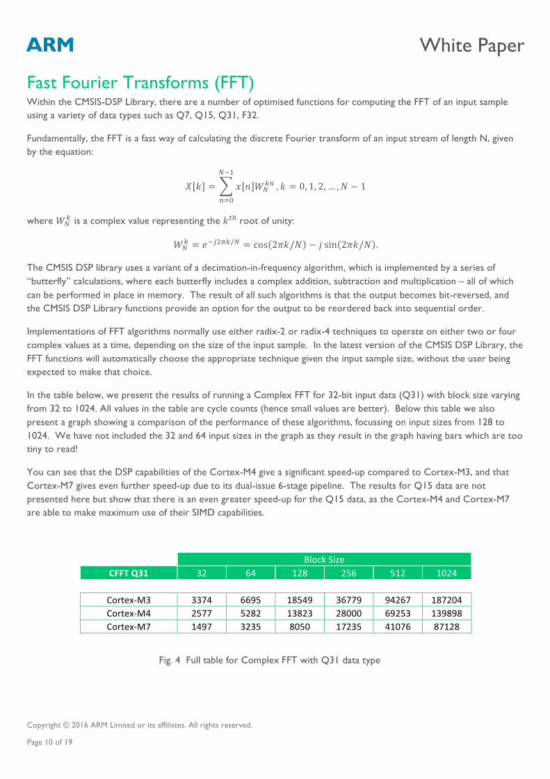
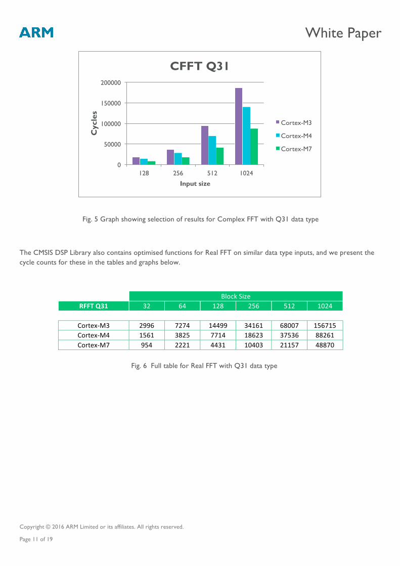
In the table below, we present the results of running a Complex FFT for 32-bit input data (Q31) with block size varying from 32 to 1024. All values in the table are cycle counts (hence small values are better). Below this table we also present a graph showing a comparison of the performance of these algorithms, focussing on input sizes from 128 to 1024. We have not included the 32 and 64 input sizes in the graph as they result in the graph having bars which are too tiny to read!
You can see that the DSP capabilities of the Cortex-M4 give a significant speed-up compared to Cortex-M3, and that Cortex-M7 gives even further speed-up due to its dual-issue 6-stage pipeline. The results for Q15 data are not presented here but show that there is an even greater speed-up for the Q15 data, as the Cortex-M4 and Cortex-M7 are able to make maximum use of their SIMD capabilities.
Block Size
CFFT Q31 32 64 128 256 512 1024
Cortex-‐M3 3374 6695 18549 36779 94267 187204 Cortex-‐M4 2577 5282 13823 28000 69253 139898 Cortex-‐M7 1497 3235 8050 17235 41076 87128
Fig. 4 Full table for Complex FFT with Q31 data type
White Paper
Copyright © 2016 ARM Limited or its affiliates. All rights reserved. Page 11 of 19
Fig. 5 Graph showing selection of results for Complex FFT with Q31 data type
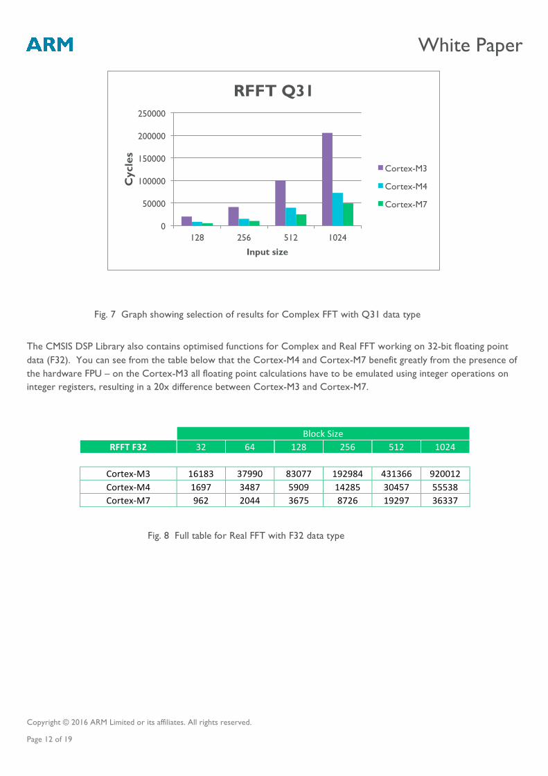
The CMSIS DSP Library also contains optimised functions for Real FFT on similar data type inputs, and we present the cycle counts for these in the tables and graphs below.
Block Size RFFT Q31 32 64 128 256 512 1024
Cortex-‐M3 2996 7274 14499 34161 68007 156715 Cortex-‐M4 1561 3825 7714 18623 37536 88261 Cortex-‐M7 954 2221 4431 10403 21157 48870
Fig. 6 Full table for Real FFT with Q31 data type
0
50000
100000
150000
200000
128 256 512 1024
Cyc
les
Input size
CFFT Q31
Cortex-M3
Cortex-M4
Cortex-M7
White Paper
Copyright © 2016 ARM Limited or its affiliates. All rights reserved. Page 12 of 19
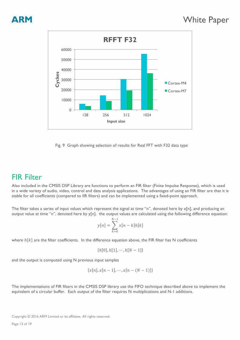
The CMSIS DSP Library also contains optimised functions for Complex and Real FFT working on 32-bit floating point data (F32). You can see from the table below that the Cortex-M4 and Cortex-M7 benefit greatly from the presence of the hardware FPU – on the Cortex-M3 all floating point calculations have to be emulated using integer operations on integer registers, resulting in a 20x difference between Cortex-M3 and Cortex-M7.
Block Size
RFFT F32 32 64 128 256 512 1024
Cortex-‐M3 16183 37990 83077 192984 431366 920012 Cortex-‐M4 1697 3487 5909 14285 30457 55538 Cortex-‐M7 962 2044 3675 8726 19297 36337
Fig. 7 Graph showing selection of results for Complex FFT with Q31 data type
Fig. 8 Full table for Real FFT with F32 data type
0
50000
100000
150000
200000
250000
128 256 512 1024
Cyc
les
Input size
RFFT Q31
Cortex-M3
Cortex-M4
Cortex-M7
White Paper
Copyright © 2016 ARM Limited or its affiliates. All rights reserved. Page 13 of 19
FIR Filter Also included in the CMSIS DSP Library are functions to perform an FIR filter (Finite Impulse Response), which is used in a wide variety of audio, video, control and data analysis applications. The advantages of using an FIR filter are that it is stable for all coefficients (compared to IIR filters) and can be implemented using a fixed-point approach. The filter takes a series of input values which represent the signal at time “n”, denoted here by x[n], and producing an output value at time “n”, denoted here by y[n]. the output values are calculated using the following difference equation:
𝑦 𝑛 = 𝑥 𝑛 − 𝑘 ℎ 𝑘!!!
!!!
where ℎ 𝑘 are the filter coefficients. In the difference equation above, the FIR filter has N coefficients
ℎ 0 , ℎ 1 ,⋯ , ℎ 𝑁 − 1
and the output is computed using N previous input samples
𝑥 𝑛 , 𝑥 𝑛 − 1 ,⋯ , 𝑥 𝑛 − (𝑁 − 1)
The implementations of FIR filters in the CMSIS DSP library use the FIFO technique described above to implement the equivalent of a circular buffer. Each output of the filter requires N multiplications and N-1 additions.
Fig. 9 Graph showing selection of results for Real FFT with F32 data type
0
10000
20000
30000
40000
50000
60000
128 256 512 1024
Cyc
kes
Input size
RFFT F32
Cortex-M4
Cortex-M7
White Paper
Copyright © 2016 ARM Limited or its affiliates. All rights reserved. Page 14 of 19
For FIR filters we talk of the number of TAPs applied to the filter. The number of TAPs simply means the number of coefficient/input pairs; the greater the number of TAPs, the more attenuation and the “narrower” the filter, and the more computation that needs to be performed.
Understanding the performance differences From the results, we can see that the DSP support instructions in Cortex-M4 and Cortex-M7 bring considerable performance advantages compared to the Cortex-M3, which is a small processor focused on a range of generic data processor and control applications. The support of a floating point unit in Cortex-M4 and Cortex-M7 also brings a significant increase in performance in a range of DSP applications that need floating point data processing.
Comparing Cortex-M4 and Cortex-M7 processors, it is also noticeable that the Cortex-M7 processor has even more performance. This is due to a number of factors:
- Cortex-M7 can execute up to two instruction per clock cycle (dual issue capability) - Cortex-M7 has dynamic branch predication - The floating point unit in Cortex-M7 is designed to support higher floating point processing capability
As a result, the Digital Signal Controller Cortex-M7 can deliver both high performance for generic control code as well as high DSP performance in a range of DSP applications, allowing chip designers to replace a range of dual core designs (generic processor + DSP) with a single processor.
Conclusion This paper covered the DSP features of the Cortex-M4 and Cortex-M7, and has shown how they can be applied to DSP algorithms. They can use the DSP extensions to the Thumb instruction set and programming techniques to match features found in a traditional DSP.
We have presented some tables of benchmark results that show how the DSP extensions of Cortex-M4 accelerate the performance of DSP algorithms compared to Cortex-M3, and how the dual-issue capabilities of Cortex-M7 deliver even higher performance on these algorithms.
As markets move more towards streaming, connectivity, and interactive user interfaces, there will be an increasing demand for performance in low power, embedded devices. Using a single microcontroller with DSP capabilities, rather than a lower performance microcontroller with separate DSP, reduces BOM cost, system-level complexity and software development costs and timescales.
We expect that an ever-increasing number of consumer devices will benefit from the high performance, low power and low-latency response of the Cortex-M4 and Cortex-M7 processors, and future processors from the Cortex-M family.
White Paper
Copyright © 2016 ARM Limited or its affiliates. All rights reserved. Page 15 of 19
Appendix
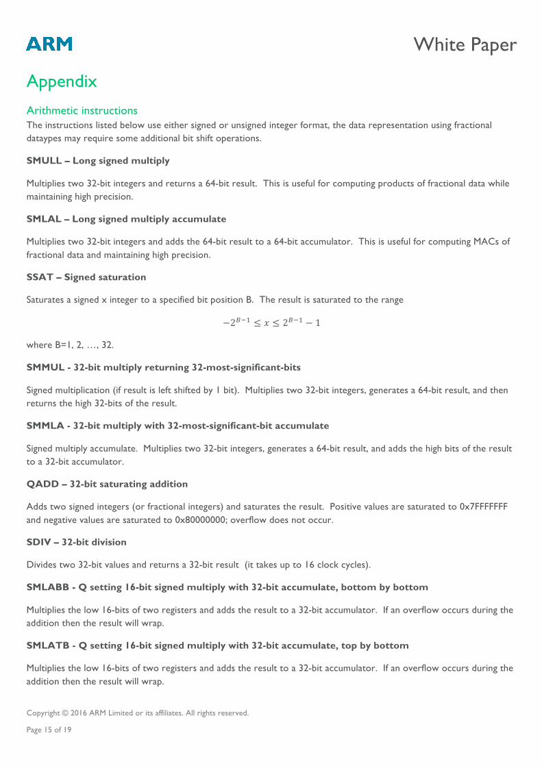
Arithmetic instructions The instructions listed below use either signed or unsigned integer format, the data representation using fractional dataypes may require some additional bit shift operations.
SMULL – Long signed multiply
Multiplies two 32-bit integers and returns a 64-bit result. This is useful for computing products of fractional data while maintaining high precision.
SMLAL – Long signed multiply accumulate
Multiplies two 32-bit integers and adds the 64-bit result to a 64-bit accumulator. This is useful for computing MACs of fractional data and maintaining high precision.
SSAT – Signed saturation
Saturates a signed x integer to a specified bit position B. The result is saturated to the range
−2!!! ≤ 𝑥 ≤ 2!!! − 1
where B=1, 2, …, 32.
SMMUL - 32-bit multiply returning 32-most-significant-bits
Signed multiplication (if result is left shifted by 1 bit). Multiplies two 32-bit integers, generates a 64-bit result, and then returns the high 32-bits of the result.
SMMLA - 32-bit multiply with 32-most-significant-bit accumulate
Signed multiply accumulate. Multiplies two 32-bit integers, generates a 64-bit result, and adds the high bits of the result to a 32-bit accumulator.
QADD – 32-bit saturating addition
Adds two signed integers (or fractional integers) and saturates the result. Positive values are saturated to 0x7FFFFFFF and negative values are saturated to 0x80000000; overflow does not occur.
SDIV – 32-bit division
Divides two 32-bit values and returns a 32-bit result (it takes up to 16 clock cycles).
SMLABB - Q setting 16-bit signed multiply with 32-bit accumulate, bottom by bottom
Multiplies the low 16-bits of two registers and adds the result to a 32-bit accumulator. If an overflow occurs during the addition then the result will wrap.
SMLATB - Q setting 16-bit signed multiply with 32-bit accumulate, top by bottom
Multiplies the low 16-bits of two registers and adds the result to a 32-bit accumulator. If an overflow occurs during the addition then the result will wrap.
White Paper
Copyright © 2016 ARM Limited or its affiliates. All rights reserved. Page 16 of 19
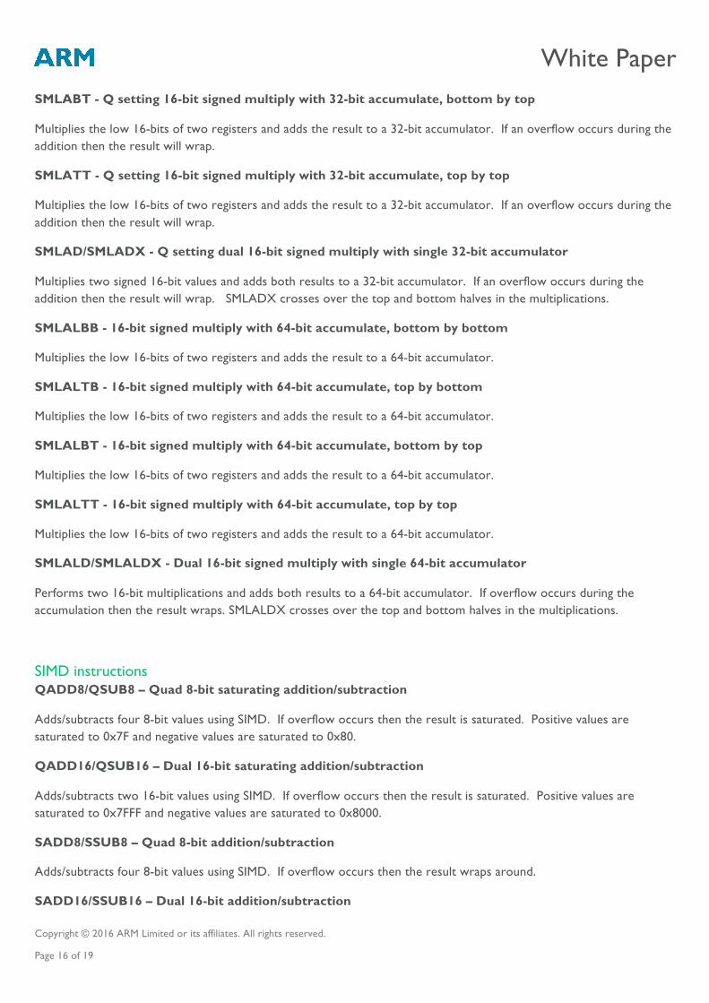
SMLABT - Q setting 16-bit signed multiply with 32-bit accumulate, bottom by top
Multiplies the low 16-bits of two registers and adds the result to a 32-bit accumulator. If an overflow occurs during the addition then the result will wrap.
SMLATT - Q setting 16-bit signed multiply with 32-bit accumulate, top by top
Multiplies the low 16-bits of two registers and adds the result to a 32-bit accumulator. If an overflow occurs during the addition then the result will wrap.
SMLAD/SMLADX - Q setting dual 16-bit signed multiply with single 32-bit accumulator
Multiplies two signed 16-bit values and adds both results to a 32-bit accumulator. If an overflow occurs during the addition then the result will wrap. SMLADX crosses over the top and bottom halves in the multiplications.
SMLALBB - 16-bit signed multiply with 64-bit accumulate, bottom by bottom
Multiplies the low 16-bits of two registers and adds the result to a 64-bit accumulator.
SMLALTB - 16-bit signed multiply with 64-bit accumulate, top by bottom
Multiplies the low 16-bits of two registers and adds the result to a 64-bit accumulator.
SMLALBT - 16-bit signed multiply with 64-bit accumulate, bottom by top
Multiplies the low 16-bits of two registers and adds the result to a 64-bit accumulator.
SMLALTT - 16-bit signed multiply with 64-bit accumulate, top by top
Multiplies the low 16-bits of two registers and adds the result to a 64-bit accumulator.
SMLALD/SMLALDX - Dual 16-bit signed multiply with single 64-bit accumulator
Performs two 16-bit multiplications and adds both results to a 64-bit accumulator. If overflow occurs during the accumulation then the result wraps. SMLALDX crosses over the top and bottom halves in the multiplications.
SIMD instructions QADD8/QSUB8 – Quad 8-bit saturating addition/subtraction
Adds/subtracts four 8-bit values using SIMD. If overflow occurs then the result is saturated. Positive values are saturated to 0x7F and negative values are saturated to 0x80.
QADD16/QSUB16 – Dual 16-bit saturating addition/subtraction
Adds/subtracts two 16-bit values using SIMD. If overflow occurs then the result is saturated. Positive values are saturated to 0x7FFF and negative values are saturated to 0x8000.
SADD8/SSUB8 – Quad 8-bit addition/subtraction
Adds/subtracts four 8-bit values using SIMD. If overflow occurs then the result wraps around.
SADD16/SSUB16 – Dual 16-bit addition/subtraction
White Paper
Copyright © 2016 ARM Limited or its affiliates. All rights reserved. Page 17 of 19
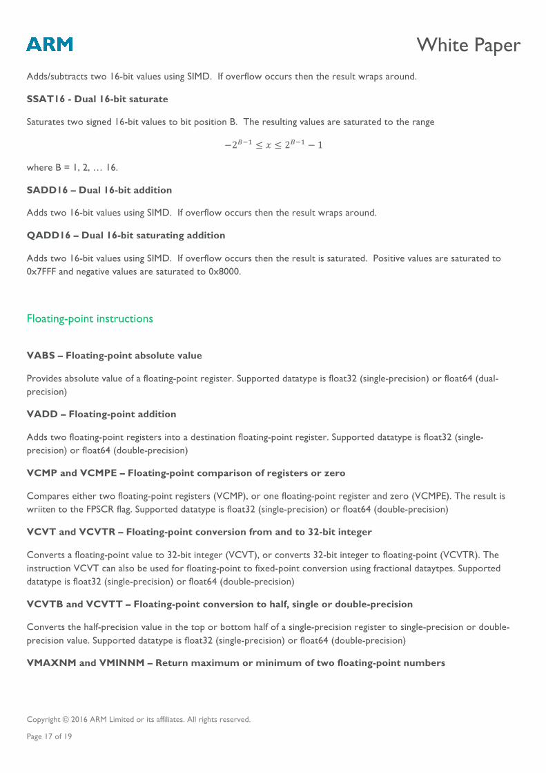
Adds/subtracts two 16-bit values using SIMD. If overflow occurs then the result wraps around.
SSAT16 - Dual 16-bit saturate
Saturates two signed 16-bit values to bit position B. The resulting values are saturated to the range
−2!!! ≤ 𝑥 ≤ 2!!! − 1
where B = 1, 2, … 16.
SADD16 – Dual 16-bit addition
Adds two 16-bit values using SIMD. If overflow occurs then the result wraps around.
QADD16 – Dual 16-bit saturating addition
Adds two 16-bit values using SIMD. If overflow occurs then the result is saturated. Positive values are saturated to 0x7FFF and negative values are saturated to 0x8000.
Floating-point instructions
VABS – Floating-point absolute value
Provides absolute value of a floating-point register. Supported datatype is float32 (single-precision) or float64 (dual-precision)
VADD – Floating-point addition
Adds two floating-point registers into a destination floating-point register. Supported datatype is float32 (single-precision) or float64 (double-precision)
VCMP and VCMPE – Floating-point comparison of registers or zero
Compares either two floating-point registers (VCMP), or one floating-point register and zero (VCMPE). The result is wriiten to the FPSCR flag. Supported datatype is float32 (single-precision) or float64 (double-precision)
VCVT and VCVTR – Floating-point conversion from and to 32-bit integer
Converts a floating-point value to 32-bit integer (VCVT), or converts 32-bit integer to floating-point (VCVTR). The instruction VCVT can also be used for floating-point to fixed-point conversion using fractional dataytpes. Supported datatype is float32 (single-precision) or float64 (double-precision)
VCVTB and VCVTT – Floating-point conversion to half, single or double-precision
Converts the half-precision value in the top or bottom half of a single-precision register to single-precision or double-precision value. Supported datatype is float32 (single-precision) or float64 (double-precision)
VMAXNM and VMINNM – Return maximum or minimum of two floating-point numbers
White Paper
Copyright © 2016 ARM Limited or its affiliates. All rights reserved. Page 18 of 19
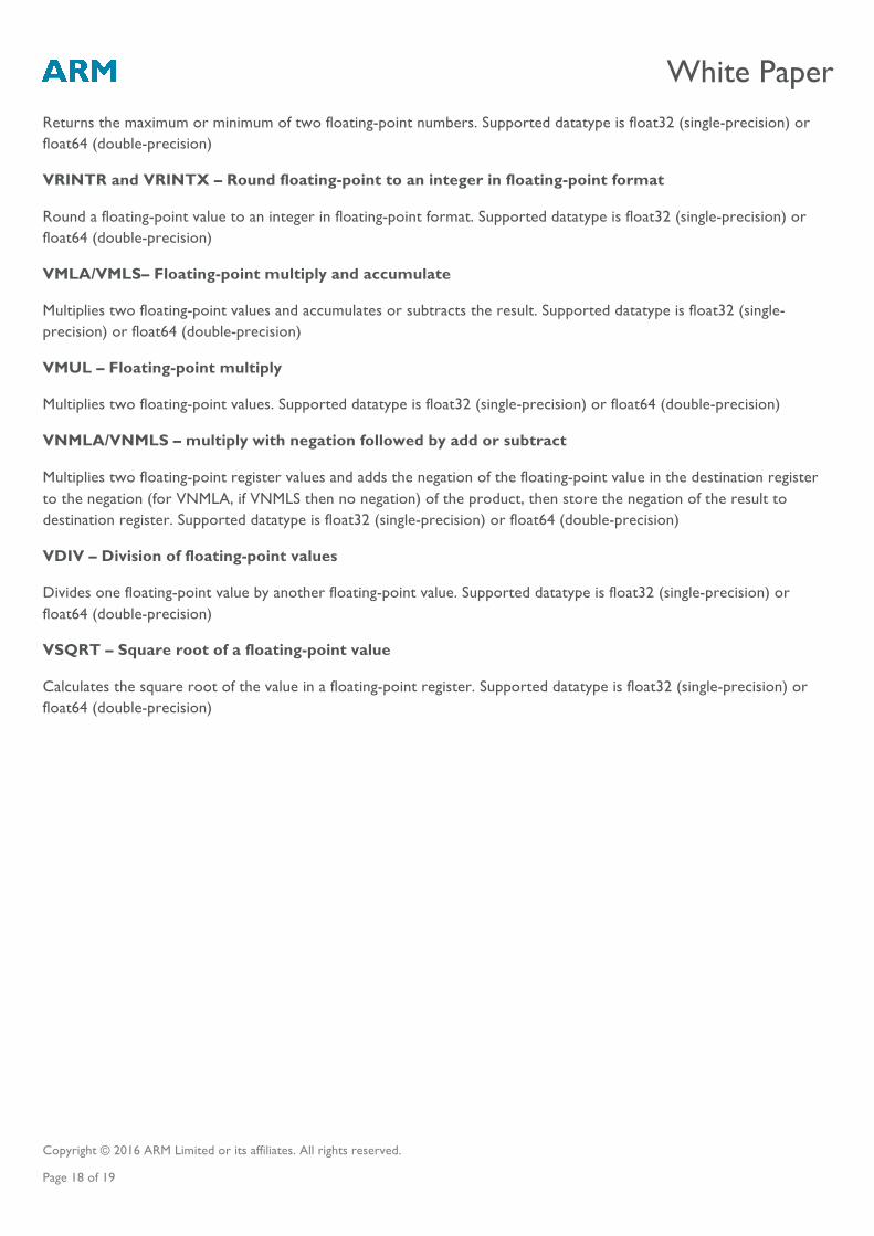
Returns the maximum or minimum of two floating-point numbers. Supported datatype is float32 (single-precision) or float64 (double-precision)
VRINTR and VRINTX – Round floating-point to an integer in floating-point format
Round a floating-point value to an integer in floating-point format. Supported datatype is float32 (single-precision) or float64 (double-precision)
VMLA/VMLS– Floating-point multiply and accumulate
Multiplies two floating-point values and accumulates or subtracts the result. Supported datatype is float32 (single-precision) or float64 (double-precision)
VMUL – Floating-point multiply
Multiplies two floating-point values. Supported datatype is float32 (single-precision) or float64 (double-precision)
VNMLA/VNMLS – multiply with negation followed by add or subtract
Multiplies two floating-point register values and adds the negation of the floating-point value in the destination register to the negation (for VNMLA, if VNMLS then no negation) of the product, then store the negation of the result to destination register. Supported datatype is float32 (single-precision) or float64 (double-precision)
VDIV – Division of floating-point values
Divides one floating-point value by another floating-point value. Supported datatype is float32 (single-precision) or float64 (double-precision)
VSQRT – Square root of a floating-point value
Calculates the square root of the value in a floating-point register. Supported datatype is float32 (single-precision) or float64 (double-precision)
White Paper
Copyright © 2016 ARM Limited or its affiliates. All rights reserved. Page 19 of 19
Trademarks The trademarks featured in this document are registered and/or unregistered trademarks of ARM Limited (or its subsidiaries) in the EU and/or elsewhere. All rights reserved. All other marks featured may be trademarks of their respective owners. For more information, visit arm.com/about/trademarks.