Embed Size (px)
Citation preview
The Essential Guide to Technical Product Specification:
Engineering Drawing
Colin Simmons and
Neil Phelps
First published in the UK in 2009 by
BSI389 Chiswick High RoadLondon W4 4AL
© British Standards Institution 2009
All rights reserved. Except as permitted under the Copyright, Designs and Patents Act 1988, no part of this publication may be reproduced, stored in a retrieval system or transmitted in any form or by any means – electronic, photocopying, recording or otherwise – without prior permission in writing from the publisher.
Whilst every care has been taken in developing and compiling this publication, BSI accepts no liability for any loss or damage caused, arising directly or indirectly in connection with reliance on its contents except to the extent that such liability may not be excluded in law.
While every effort has been made to trace all copyright holders, anyone claiming copyright should get in touch with the BSI at the above address.
BSI has no responsibility for the persistence or accuracy of URLs for external or third-party internet websites referred to in this book, and does not guarantee that any content on such websites is, or will remain, accurate or appropriate.
The right of Colin Simmons and Neil Phelps to be identified as the authors of this Work has been asserted by them in accordance with sections 77 and 78 of the Copyright, Designs and Patents Act 1988.
Typeset in Optima and Gill Sans by Monolith – http://www.monolith.uk.comPrinted in Great Britain by Berforts Group, Stevenage
British Library Cataloguing in Publication DataA catalogue record for this book is available from the British Library
ISBN 978 0 580 62673 9
v
Contents
Introduction viiDimensioning and tolerancing of size 1
1.1 Introduction 11.2 General principles 11.3 Types of dimension 21.4 Dimensioning conventions 31.5 Arrangement of dimensions 41.6 Methods for dimensioning common features 91.7 Dimensioning screw threads and threaded parts 121.8 Dimensioning chamfers and countersinks 131.9 Equally spaced repeated features 141.10 Dimensioning of curved profiles 161.11 Dimensioning of keyways 171.12 Tolerancing 181.13 Interpretations of limits of size for a feature-of-size 191.14 Datum surfaces and functional requirements 211.15 Relevant standards 21
Geometric tolerancing datums and datum systems 232.1 Introduction 232.2 Terms and definitions 232.3 Basic concepts 262.4 Symbols 272.5 Tolerance frame 292.6 Toleranced features 292.7 Tolerance zones 322.8 Datums and datum systems 372.9 Supplementary indications 452.10 Examples of geometrical tolerancing 642.11 Relevant standards 114
Graphical symbols for the indication of surface texture 1153.1 Introduction 1153.2 The basic graphical symbol 1153.3 Expanded graphical symbols 1153.4 Mandatory positions for the indication of surface texture requirements 1163.5 Surface texture parameters 1173.6 Indication of special surface texture characteristics 1183.7 Indications on drawings 1203.8 Relevant standards 123
vi The Essential Guide to Technical Product Specification: Engineering Drawing
Welding, brazed and soldered joints – Symbolic representation 1254.1 Introduction 1254.2 Relevant standards 133
Limits and fits 1355.1 Introduction 1355.2 Selected ISO fits – Hole basis 1355.3 Selected ISO fits – Shaft basis 1385.4 Methods of specifying required fits 1405.5 Relevant standards 140
Metric screw threads 1416.1 Introduction 1416.2 Thread designation 1416.3 Relevant standards 168
Illustrated index to BS 8888 169Normative references 169
vii
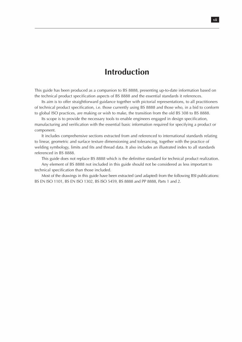
Introduction
This guide has been produced as a companion to BS 8888, presenting up-to-date information based on the technical product specification aspects of BS 8888 and the essential standards it references.
Its aim is to offer straightforward guidance together with pictorial representations, to all practitioners of technical product specification, i.e. those currently using BS 8888 and those who, in a bid to conform to global ISO practices, are making or wish to make, the transition from the old BS 308 to BS 8888.
Its scope is to provide the necessary tools to enable engineers engaged in design specification, manufacturing and verification with the essential basic information required for specifying a product or component.
It includes comprehensive sections extracted from and referenced to international standards relating to linear, geometric and surface texture dimensioning and tolerancing, together with the practice of welding symbology, limits and fits and thread data. It also includes an illustrated index to all standards referenced in BS 8888.
This guide does not replace BS 8888 which is the definitive standard for technical product realization.Any element of BS 8888 not included in this guide should not be considered as less important to
technical specification than those included.Most of the drawings in this guide have been extracted (and adapted) from the following BSI publications:
BS EN ISO 1101, BS EN ISO 1302, BS ISO 5459, BS 8888 and PP 8888, Parts 1 and 2.
1
Chapter 1
Dimensioning and tolerancing of size
1.1 Introduction
Dimensioning is the process of applying measurements to a technical drawing. It is crucial to the whole process by which the designer will communicate the information required for the manufacture and verification of products.
1.2 General principles
Dimensions shall be applied to the drawing accurately, clearly and unambiguously. The following points shall be regarded as general dimensioning principles to be applied to all technical drawings.
• Each dimension necessary for the definition of the finished product shall be shown once only.• Never calculate a dimension from the other dimensions shown on the drawing, nor scale the drawing.• There shall be no more dimensions than are necessary to completely define the product.• Preferred sizes shall be used whenever possible (see notes).• Linear dimensions shall be expressed in millimetres (unit symbol ‘mm’). If this information is stated
on the drawing, the unit symbol ‘mm’ may be omitted. If other units are used, the symbols shall be shown with their respective values.
• Dimensions shall be expressed to the least number of significant figures, e.g. 45 not 45,0.• The decimal marker shall be a bold comma, given a full letter space and placed on the baseline.• Where four or more numerals are to the left or right of the decimal marker, a full space shall divide
each group of three numerals, counting from the position of the decimal marker, e.g. 400 or 100 but 12 500 (see notes).
• A zero shall precede a decimal of less than one, e.g. 0,5.• An angular dimension shall be expressed in degrees and minutes, e.g. 20° and 22° 30’ or,
alternatively, as a decimal, e.g. 30,5°.• A full space shall be left between the degree symbol and the minute numeral.• When an angle is less than one degree, it shall be preceded by a zero, e.g. 0° 30’.
NOTES: Preferred sizes are those referring to standard material stock sizes and standard components such as nuts, bolts, studs and screws.
Decimal marker points or commas are not used to separate groups of numerals. This causes ambiguity since the decimal marker is denoted by a comma.
2 The Essential Guide to Technical Product Specification: Engineering Drawing
1.3 Types of dimension
For the purposes of this section, the following definitions apply.
dimensionnumerical value expressed in appropriate units of measurement and indicated graphically on technical drawings with lines, symbols and notes
Dimensions are classified according to the following types.
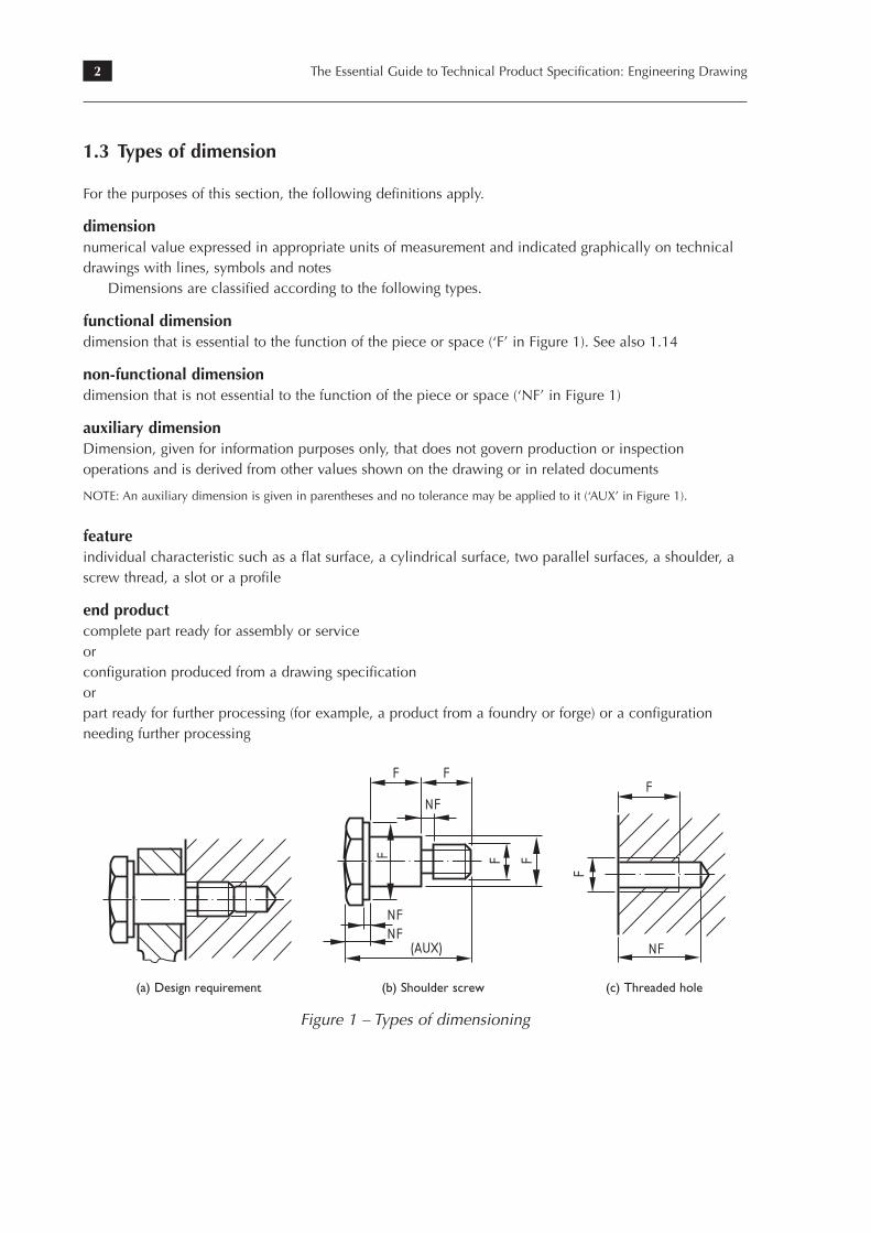
functional dimensiondimension that is essential to the function of the piece or space (‘F’ in Figure 1). See also 1.14
non-functional dimensiondimension that is not essential to the function of the piece or space (‘NF’ in Figure 1)
auxiliary dimensionDimension, given for information purposes only, that does not govern production or inspection operations and is derived from other values shown on the drawing or in related documents
NOTE: An auxiliary dimension is given in parentheses and no tolerance may be applied to it (‘AUX’ in Figure 1).
featureindividual characteristic such as a flat surface, a cylindrical surface, two parallel surfaces, a shoulder, a screw thread, a slot or a profile
end productcomplete part ready for assembly or serviceorconfiguration produced from a drawing specificationorpart ready for further processing (for example, a product from a foundry or forge) or a configuration needing further processing
6. Dimensioning of technical drawings
Endproduct: complete part ready for assembly or service, or a configuration produced
from a drawing specification. An end product may also be a part ready for further
processing (for example, a product from a foundry or forge) or a configuration needing
further processing.
67
Figure 57: Types of
dimensioning
(a) Design requirement
F F
FF F
NF
NFNF
(AUX)
(b) Shoulder screw
F
F
NF
(c) Threaded hole
6. Dimensioning of technical drawings
Endproduct: complete part ready for assembly or service, or a configuration produced
from a drawing specification. An end product may also be a part ready for further
processing (for example, a product from a foundry or forge) or a configuration needing
further processing.
67
Figure 57: Types of
dimensioning
(a) Design requirement
F F
FF F
NF
NFNF
(AUX)
(b) Shoulder screw
F
F
NF
(c) Threaded hole (a) Design requirement (b) Shoulder screw (c) Threaded hole
Figure 1 – Types of dimensioning
3Dimensioning and tolerancing of size
1.4 Dimensioning conventions
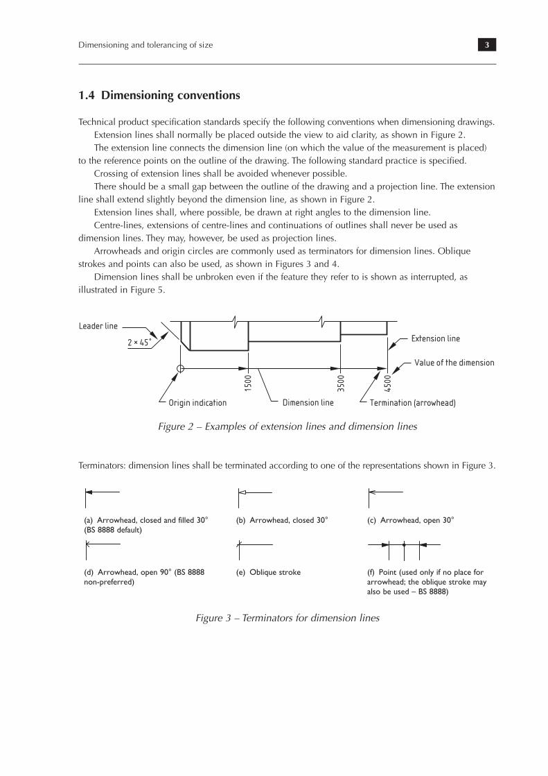
Technical product specification standards specify the following conventions when dimensioning drawings.Extension lines shall normally be placed outside the view to aid clarity, as shown in Figure 2.The extension line connects the dimension line (on which the value of the measurement is placed)
to the reference points on the outline of the drawing. The following standard practice is specified.Crossing of extension lines shall be avoided whenever possible.There should be a small gap between the outline of the drawing and a projection line. The extension
line shall extend slightly beyond the dimension line, as shown in Figure 2.Extension lines shall, where possible, be drawn at right angles to the dimension line.Centre-lines, extensions of centre-lines and continuations of outlines shall never be used as
dimension lines. They may, however, be used as projection lines.Arrowheads and origin circles are commonly used as terminators for dimension lines. Oblique
strokes and points can also be used, as shown in Figures 3 and 4.Dimension lines shall be unbroken even if the feature they refer to is shown as interrupted, as
illustrated in Figure 5.
68
6.4 Dimensioning conventions
6.4.1 General
Technical product specification standards recommend the following conventions
when dimensioning drawings.
6.4.2 Extension lines and dimension lines
The extension line connects the dimension line (on which the value of the measure-
ment is placed) to the reference points on the outline of the drawing. The following
standard practice is recommended.
] Extension lines (continuous narrow line type 01.1.3, see Table 1) should normally
be placed outside of the view to aid clarity, as shown in Figure 58.
] Crossing of extension lines should be avoided whenever possible.
] There should be a small gap between the outline of the drawing and a projection
line. The extension line should extend slightly beyond the dimension line, as shown
in Figure 58.
] Extension lines should normally be drawn at right angles to the dimension line.
] Centre-lines, extensions of centre-lines and continuations of outlines are never to
be used as dimension lines. They may, however, be used as projection lines.
] Arrowheads and common origin circles are used as terminators for dimension
lines, as shown in Figures 59 and 60.
] Dimension lines should be unbroken even if the feature they refer to is shown as
interrupted, as illustrated in Figure 61.
Drawing practice
Leader line
2 × 45
Origin indication Termination (arrowhead)
Extension line
Value of the dimension
1500
3500
4500
Dimension line
Figure 58: Examples of extension lines and dimension linesFigure 2 – Examples of extension lines and dimension lines
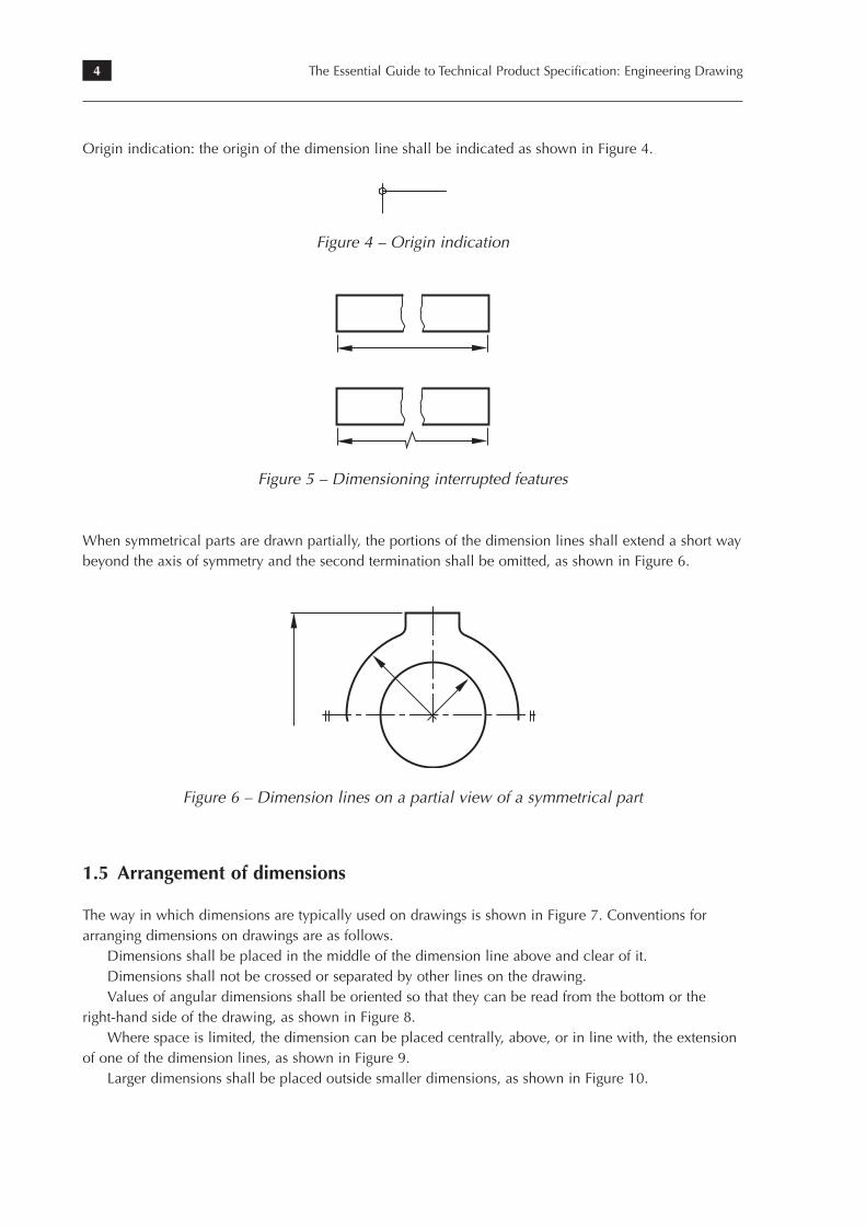
Terminators: dimension lines shall be terminated according to one of the representations shown in Figure 3.
6. Dimensioning of technical drawings
] When symmetrical parts are drawn partially, the portions of the dimension lines
extend a short way beyond the axis of symmetry and the second termination is
omitted, as shown in Figure 62.
69
Figure 60: Origin
indication
Figure 59: Terminators for
dimension lines
(a) Arrowhead, closed
and filled 30° (BS 8888
default)
(f) Point (used only if no
place for arrowhead; the
oblique stroke may also
be used – BS 8888)
(e) Oblique stroke(d) Arrowhead, open 90°
(BS 8888 non-preferred)
(b) Arrowhead, closed
30°
(c) Arrowhead, open 30°
Figure 61: Dimensioning
interrupted features
Figure 62: Dimension lines
on a partial view of a
symmetrical part
(a) Arrowhead, closed and filled 30° (BS 8888 default)
(b) Arrowhead, closed 30° (c) Arrowhead, open 30°
6. Dimensioning of technical drawings
] When symmetrical parts are drawn partially, the portions of the dimension lines
extend a short way beyond the axis of symmetry and the second termination is
omitted, as shown in Figure 62.
69
Figure 60: Origin
indication
Figure 59: Terminators for
dimension lines
(a) Arrowhead, closed
and filled 30° (BS 8888
default)
(f) Point (used only if no
place for arrowhead; the
oblique stroke may also
be used – BS 8888)
(e) Oblique stroke(d) Arrowhead, open 90°
(BS 8888 non-preferred)
(b) Arrowhead, closed
30°
(c) Arrowhead, open 30°
Figure 61: Dimensioning
interrupted features
Figure 62: Dimension lines
on a partial view of a
symmetrical part
(d) Arrowhead, open 90° (BS 8888 non-preferred)
(e) Oblique stroke (f) Point (used only if no place for arrowhead; the oblique stroke may also be used – BS 8888)
Figure 3 – Terminators for dimension lines
4 The Essential Guide to Technical Product Specification: Engineering Drawing
Origin indication: the origin of the dimension line shall be indicated as shown in Figure 4.
6. Dimensioning of technical drawings
] When symmetrical parts are drawn partially, the portions of the dimension lines
extend a short way beyond the axis of symmetry and the second termination is
omitted, as shown in Figure 62.
69
Figure 60: Origin
indication
Figure 59: Terminators for
dimension lines
(a) Arrowhead, closed
and filled 30° (BS 8888
default)
(f) Point (used only if no
place for arrowhead; the
oblique stroke may also
be used – BS 8888)
(e) Oblique stroke(d) Arrowhead, open 90°
(BS 8888 non-preferred)
(b) Arrowhead, closed
30°
(c) Arrowhead, open 30°
Figure 61: Dimensioning
interrupted features
Figure 62: Dimension lines
on a partial view of a
symmetrical part
Figure 4 – Origin indication
6. Dimensioning of technical drawings
] When symmetrical parts are drawn partially, the portions of the dimension lines
extend a short way beyond the axis of symmetry and the second termination is
omitted, as shown in Figure 62.
69
Figure 60: Origin
indication
Figure 59: Terminators for
dimension lines
(a) Arrowhead, closed
and filled 30° (BS 8888
default)
(f) Point (used only if no
place for arrowhead; the
oblique stroke may also
be used – BS 8888)
(e) Oblique stroke(d) Arrowhead, open 90°
(BS 8888 non-preferred)
(b) Arrowhead, closed
30°
(c) Arrowhead, open 30°
Figure 61: Dimensioning
interrupted features
Figure 62: Dimension lines
on a partial view of a
symmetrical part
Figure 5 – Dimensioning interrupted features
When symmetrical parts are drawn partially, the portions of the dimension lines shall extend a short way beyond the axis of symmetry and the second termination shall be omitted, as shown in Figure 6.
6. Dimensioning of technical drawings
] When symmetrical parts are drawn partially, the portions of the dimension lines
extend a short way beyond the axis of symmetry and the second termination is
omitted, as shown in Figure 62.
69
Figure 60: Origin
indication
Figure 59: Terminators for
dimension lines
(a) Arrowhead, closed
and filled 30° (BS 8888
default)
(f) Point (used only if no
place for arrowhead; the
oblique stroke may also
be used – BS 8888)
(e) Oblique stroke(d) Arrowhead, open 90°
(BS 8888 non-preferred)
(b) Arrowhead, closed
30°
(c) Arrowhead, open 30°
Figure 61: Dimensioning
interrupted features
Figure 62: Dimension lines
on a partial view of a
symmetrical part
Figure 6 – Dimension lines on a partial view of a symmetrical part
1.5 Arrangement of dimensions
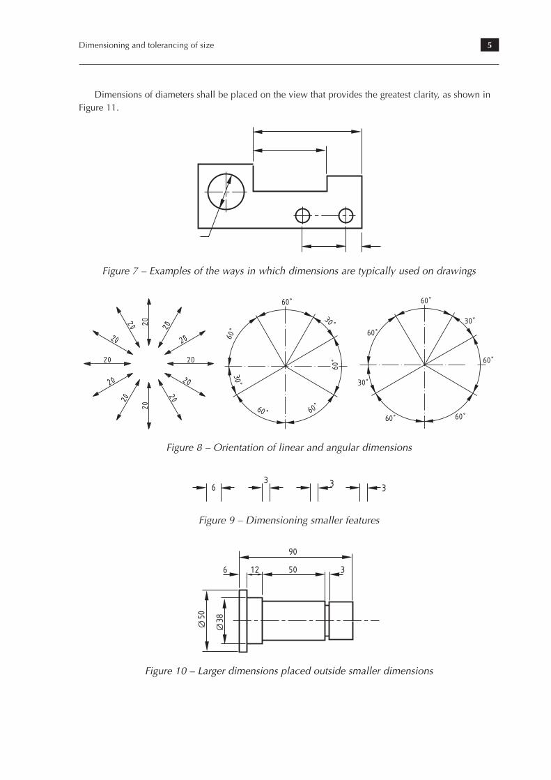
The way in which dimensions are typically used on drawings is shown in Figure 7. Conventions for arranging dimensions on drawings are as follows.
Dimensions shall be placed in the middle of the dimension line above and clear of it.Dimensions shall not be crossed or separated by other lines on the drawing.Values of angular dimensions shall be oriented so that they can be read from the bottom or the
right-hand side of the drawing, as shown in Figure 8.Where space is limited, the dimension can be placed centrally, above, or in line with, the extension
of one of the dimension lines, as shown in Figure 9.Larger dimensions shall be placed outside smaller dimensions, as shown in Figure 10.
5Dimensioning and tolerancing of size
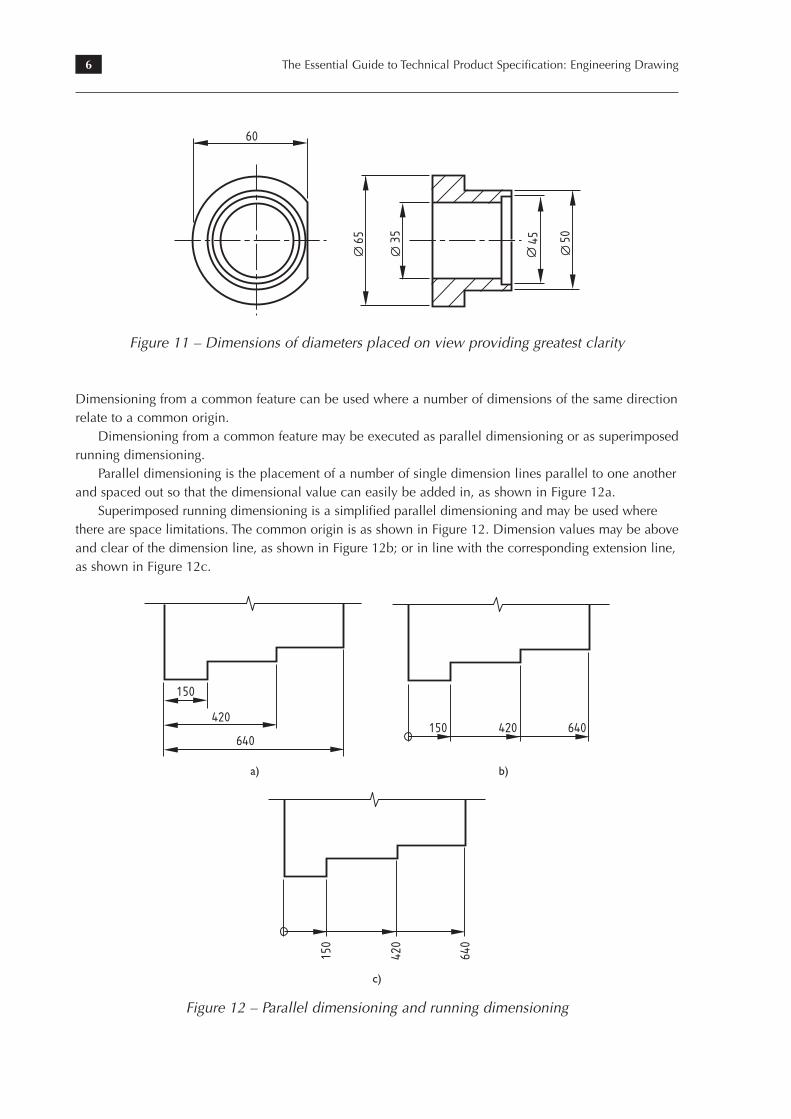
Dimensions of diameters shall be placed on the view that provides the greatest clarity, as shown in Figure 11.
70
6.4.3 Dimension line terminator and origin indication
Terminators: dimension lines are terminated according to one of the representations
shown in Figure 59.
Origin indication: the origin of the dimension line is indicated as shown in Figure 60.
6.5 Arrangement of dimensions
The way in which dimensions are typically used on drawings is shown in Figure 63.
Conventions for arranging dimensions on drawings are as follows.
] Dimensions should be placed in the middle of the dimension line above and clear
of it.
] Dimensions should not be crossed or separated by other lines on the drawing.
] Values of angular dimensions are to be oriented so that they can be read from the
bottom or the right-hand side of the drawing (see Figures 64, 65, 67 and 70).
] Where space is limited, the dimension can be placed centrally, above, or in line
with, the extension of one of the dimension lines (see Figure 66).
] Larger dimensions are placed outside smaller dimensions (see Figure 67).
] Dimensions of diameters should be placed on the view that provides the greatest
clarity (see Figure 68).
Drawing practice
Figure 63: Examples of the
ways in which dimensions
are typically used on
drawings
Figure 7 – Examples of the ways in which dimensions are typically used on drawings
6. Dimensioning of technical drawings
71
Figure 64: Orientation of
linear dimensions
60
30
60
60 60
30
60
Figure 65: Orientation of
angular dimensions
60
30
60
60 60
60
30
(a)
(b)
6. Dimensioning of technical drawings
71
Figure 64: Orientation of
linear dimensions
60
30
60
60 60
30
60
Figure 65: Orientation of
angular dimensions
60
30
60
60 60
60
30
(a)
(b)
6. Dimensioning of technical drawings
71
Figure 64: Orientation of
linear dimensions
60
30
60
60 60
30
60
Figure 65: Orientation of
angular dimensions
60
30
60
60 60
60
30
(a)
(b)
Figure 8 – Orientation of linear and angular dimensions
72
6.6 Examples of dimensioning methods
Dimensioning from a common feature is used where a number of dimensions of the
same direction relate to a common origin.
Dimensioning from a common feature may be executed as parallel dimensioning or as
superimposed running dimensioning.
Parallel dimensioning is the placement of a number of single dimension lines parallel
to one another and spaced out so that the dimensional value can easily be added in
(see Figure 69).
Drawing practice
63 3 3
Figure 66: Dimensioning
smaller features
90
6 12 50 3
50 38
Figure 67: Larger
dimensions placed outside
smaller dimensions
65 35 45 50
60Figure 68: Dimensions of
diameters placed on view
providing the greatest
clarity
Figure 9 – Dimensioning smaller features
72
6.6 Examples of dimensioning methods
Dimensioning from a common feature is used where a number of dimensions of the
same direction relate to a common origin.
Dimensioning from a common feature may be executed as parallel dimensioning or as
superimposed running dimensioning.
Parallel dimensioning is the placement of a number of single dimension lines parallel
to one another and spaced out so that the dimensional value can easily be added in
(see Figure 69).
Drawing practice
63 3 3
Figure 66: Dimensioning
smaller features
90
6 12 50 3
50 38
Figure 67: Larger
dimensions placed outside
smaller dimensions
65 35 45 50
60Figure 68: Dimensions of
diameters placed on view
providing the greatest
clarity
Figure 10 – Larger dimensions placed outside smaller dimensions
6 The Essential Guide to Technical Product Specification: Engineering Drawing
72
6.6 Examples of dimensioning methods
Dimensioning from a common feature is used where a number of dimensions of the
same direction relate to a common origin.
Dimensioning from a common feature may be executed as parallel dimensioning or as
superimposed running dimensioning.
Parallel dimensioning is the placement of a number of single dimension lines parallel
to one another and spaced out so that the dimensional value can easily be added in
(see Figure 69).
Drawing practice
63 3 3
Figure 66: Dimensioning
smaller features
90
6 12 50 3
50 38
Figure 67: Larger
dimensions placed outside
smaller dimensions
65 35 45 50
60Figure 68: Dimensions of
diameters placed on view
providing the greatest
clarity
Figure 11 – Dimensions of diameters placed on view providing greatest clarity
Dimensioning from a common feature can be used where a number of dimensions of the same direction relate to a common origin.
Dimensioning from a common feature may be executed as parallel dimensioning or as superimposed running dimensioning.
Parallel dimensioning is the placement of a number of single dimension lines parallel to one another and spaced out so that the dimensional value can easily be added in, as shown in Figure 12a.
Superimposed running dimensioning is a simplified parallel dimensioning and may be used where there are space limitations. The common origin is as shown in Figure 12. Dimension values may be above and clear of the dimension line, as shown in Figure 12b; or in line with the corresponding extension line, as shown in Figure 12c.
6. Dimensioning of technical drawings
Superimposed running dimensioning is a simplified parallel dimensioning and may
be used where there are space limitations. The common origin is shown as in Figure 70.
Dimension values may be:
] above and clear of the dimension line (see Figure 70a); or
] in line with the corresponding extension line (see Figure 70b).
73
150
420
640
Figure 69: Parallel
dimensioning
Figure 70: Examples of
running dimensioning
150 420 640
(a)
150
420
640
(b)
a) b)
6. Dimensioning of technical drawings
Superimposed running dimensioning is a simplified parallel dimensioning and may
be used where there are space limitations. The common origin is shown as in Figure 70.
Dimension values may be:
] above and clear of the dimension line (see Figure 70a); or
] in line with the corresponding extension line (see Figure 70b).
73
150
420
640
Figure 69: Parallel
dimensioning
Figure 70: Examples of
running dimensioning
150 420 640
(a)
150
420
640
(b) c)
Figure 12 – Parallel dimensioning and running dimensioning
7Dimensioning and tolerancing of size
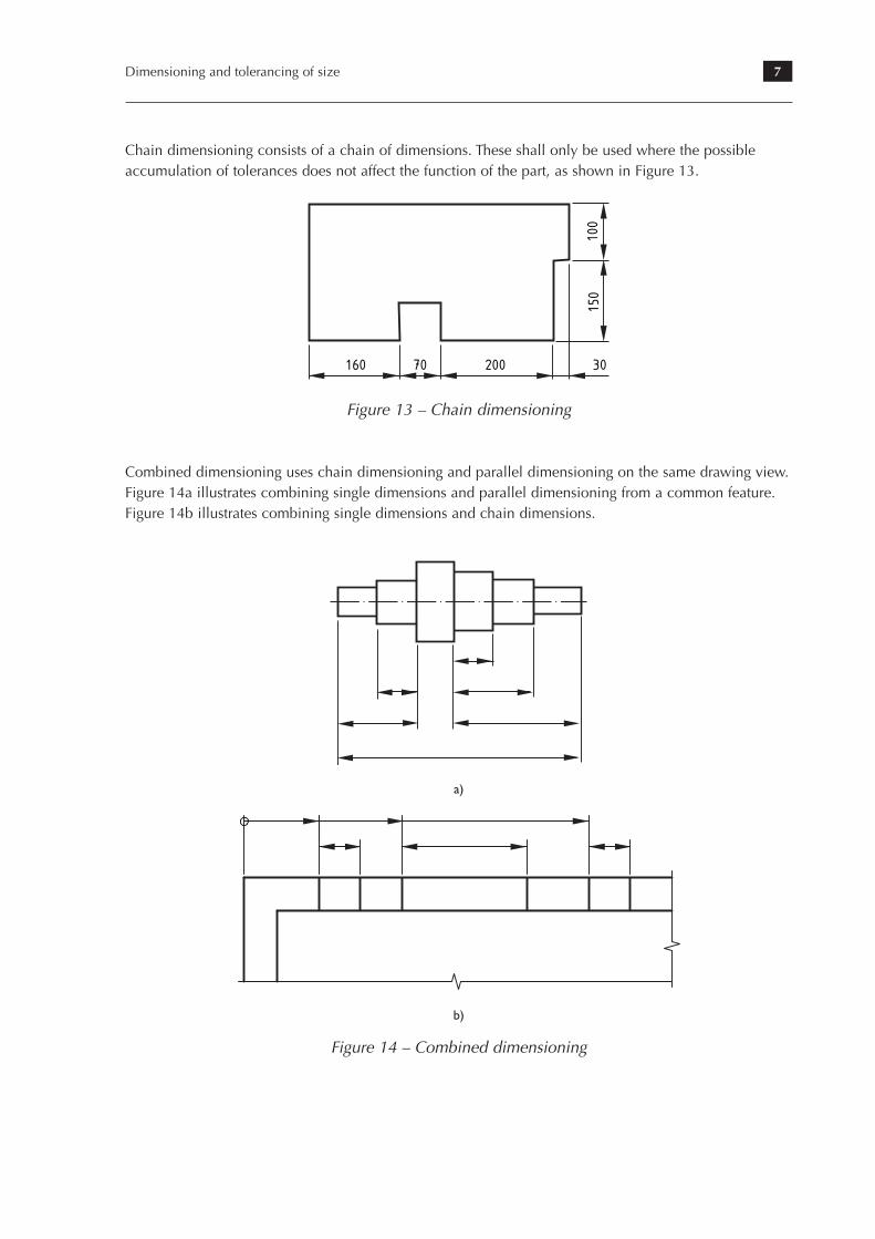
Chain dimensioning consists of a chain of dimensions. These shall only be used where the possible accumulation of tolerances does not affect the function of the part, as shown in Figure 13.
74
Chain dimensioning consists of a chain of dimensions. These should only be used
where the possible accumulation of tolerances does not affect the function of the part
(see Figure 71).
Combined dimensioning uses chain dimensioning and parallel dimensioning on the
same drawing (see Figure 72).
Drawing practice
160 70 200 30
150
100
Figure 71: Chain
dimensioning
Figure 72: Examples of
combined dimensioning
(a) Combining single dimensions and parallel
dimensioning from a common feature
(b) Combining single dimensions and chain dimensions
Figure 13 – Chain dimensioning
Combined dimensioning uses chain dimensioning and parallel dimensioning on the same drawing view. Figure 14a illustrates combining single dimensions and parallel dimensioning from a common feature. Figure 14b illustrates combining single dimensions and chain dimensions.
74
Chain dimensioning consists of a chain of dimensions. These should only be used
where the possible accumulation of tolerances does not affect the function of the part
(see Figure 71).
Combined dimensioning uses chain dimensioning and parallel dimensioning on the
same drawing (see Figure 72).
Drawing practice
160 70 200 30
150
100
Figure 71: Chain
dimensioning
Figure 72: Examples of
combined dimensioning
(a) Combining single dimensions and parallel
dimensioning from a common feature
(b) Combining single dimensions and chain dimensions
a)
74
Chain dimensioning consists of a chain of dimensions. These should only be used
where the possible accumulation of tolerances does not affect the function of the part
(see Figure 71).
Combined dimensioning uses chain dimensioning and parallel dimensioning on the
same drawing (see Figure 72).
Drawing practice
160 70 200 30
150
100
Figure 71: Chain
dimensioning
Figure 72: Examples of
combined dimensioning
(a) Combining single dimensions and parallel
dimensioning from a common feature
(b) Combining single dimensions and chain dimensionsb)
Figure 14 – Combined dimensioning
8 The Essential Guide to Technical Product Specification: Engineering Drawing
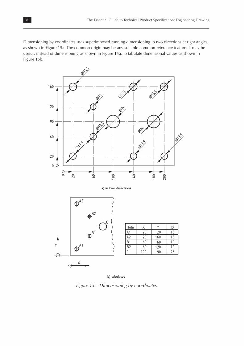
Dimensioning by coordinates uses superimposed running dimensioning in two directions at right angles, as shown in Figure 15a. The common origin may be any suitable common reference feature. It may be useful, instead of dimensioning as shown in Figure 15a, to tabulate dimensional values as shown in Figure 15b.
6. Dimensioning of technical drawings
Dimensioningbycoordinatesuses superimposed running dimensioning in two direc-
tions at right angles, as shown in Figure 73. The common origin may be any suitable
common reference feature. It may be useful, instead of dimensioning as shown in
Figure 73, to tabulate dimensional values as shown in Figure 74.
75
∆15,5
∆15,5
∆26
∆26
∆11 ∆15,5
∆13,5
∆13,5∆13,5 ∆13,5
160
120
90
60
20
0
0 20 60 100
140
180
200
Figure 73: Dimensioning
by coordinates (two
directions)
Y
X
A1
A2
B1
C
B2
∆
16060
12090
Figure 74: Dimensioning
by coordinates (tabulated)
a) in two directions
6. Dimensioning of technical drawings
Dimensioningbycoordinatesuses superimposed running dimensioning in two direc-
tions at right angles, as shown in Figure 73. The common origin may be any suitable
common reference feature. It may be useful, instead of dimensioning as shown in
Figure 73, to tabulate dimensional values as shown in Figure 74.
75
∆15,5
∆15,5
∆26
∆26
∆11 ∆15,5
∆13,5
∆13,5∆13,5 ∆13,5
160
120
90
60
20
0
0 20 60 100
140
180
200
Figure 73: Dimensioning
by coordinates (two
directions)
Y
X
A1
A2
B1
C
B2
∆
16060
12090
Figure 74: Dimensioning
by coordinates (tabulated)
b) tabulated
Figure 15 – Dimensioning by coordinates
9Dimensioning and tolerancing of size
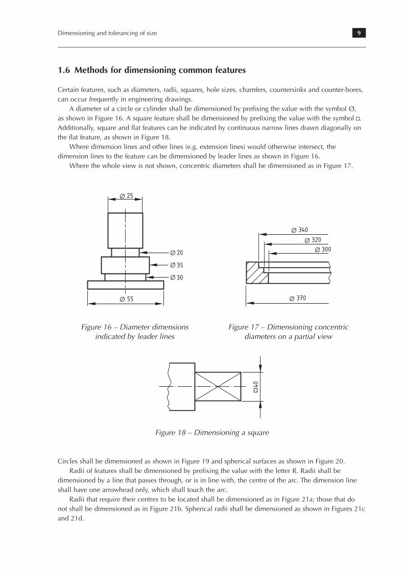
1.6 Methods for dimensioning common features
Certain features, such as diameters, radii, squares, hole sizes, chamfers, countersinks and counter-bores, can occur frequently in engineering drawings.
A diameter of a circle or cylinder shall be dimensioned by prefixing the value with the symbol Ø, as shown in Figure 16. A square feature shall be dimensioned by prefixing the value with the symbol . Additionally, square and flat features can be indicated by continuous narrow lines drawn diagonally on the flat feature, as shown in Figure 18.
Where dimension lines and other lines (e.g. extension lines) would otherwise intersect, the dimension lines to the feature can be dimensioned by leader lines as shown in Figure 16.
Where the whole view is not shown, concentric diameters shall be dimensioned as in Figure 17.
76
6.7 Methods for dimensioning commonfeatures
6.7.1 General
Certain features, such as diameters, radii, hole sizes, chamfers, countersinks and
counter-bores, can occur frequently in engineering drawings and students should be
aware of how to dimension them to BS 8888:2006.
6.7.2 Diameters
A diameter of a circle or cylinder is dimensioned by prefixing the value with the symbol
Ø. This symbol should be as large as the following numerals and the slanting line
should be about 30° clockwise from the vertical, in the direction in which it is to be read
(see Figure 68). It has already been pointed out (see Figure 68) that the dimensions
should be placed on the view that most clearly shows the information.
Where dimension lines and other lines (e.g. extension lines) would otherwise intersect,
the dimension lines to the feature can be dimensioned by leader lines as shown
in Figure 75. Where the whole view is not shown, concentric diameters can be
dimensioned as in Figure 76.
Circles are to be dimensioned as shown in Figure 77 and spherical surfaces as shown in
Figure 78.
Drawing practice
25
55
20
35
30
Figure 75: Diameter
dimensions indicated by
leader lines
6. Dimensioning of technical drawings
Holes are to be dimensioned as shown in Figure 79. The depth of the drilled hole when
given in note form refers to the depth of the cylindrical portion of the hole and not to
the extremity made by the point of the drill, unless otherwise specified.
77
340
320300
370
Figure 76: Dimensioning
concentric diameters on
partial views
1010
20
40
NOTE. Leader line shouldbe in line with centreof circle
Figure 77: Dimensioning a
circle
Figure 78: Dimensioning
spherical diameters
S 20
(a)
S∆50
(b)
Figure 16 – Diameter dimensions indicated by leader lines
Figure 17 – Dimensioning concentric diameters on a partial view
12. Dimensioning
75
R10R15
Figure 78: Radial values
S∆50 Figure 81: Spherical
diameter values
SR12
SR60
Figure 80: Spherical radius
values
40
Figure 79: Square values
101
Figure 18 – Dimensioning a square
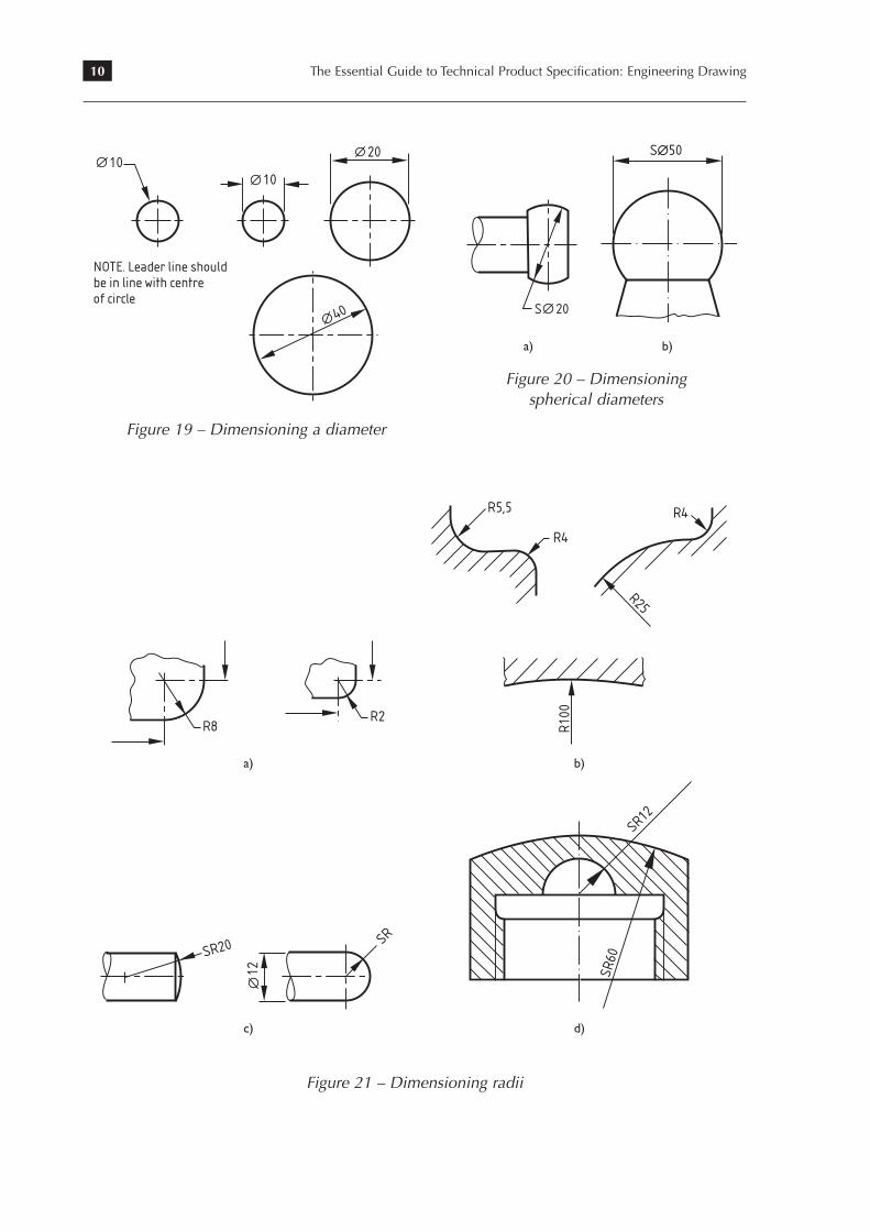
Circles shall be dimensioned as shown in Figure 19 and spherical surfaces as shown in Figure 20.Radii of features shall be dimensioned by prefixing the value with the letter R. Radii shall be
dimensioned by a line that passes through, or is in line with, the centre of the arc. The dimension line shall have one arrowhead only, which shall touch the arc.
Radii that require their centres to be located shall be dimensioned as in Figure 21a; those that do not shall be dimensioned as in Figure 21b. Spherical radii shall be dimensioned as shown in Figures 21c and 21d.
10 The Essential Guide to Technical Product Specification: Engineering Drawing
6. Dimensioning of technical drawings
Holes are to be dimensioned as shown in Figure 79. The depth of the drilled hole when
given in note form refers to the depth of the cylindrical portion of the hole and not to
the extremity made by the point of the drill, unless otherwise specified.
77
340
320300
370
Figure 76: Dimensioning
concentric diameters on
partial views
1010
20
40
NOTE. Leader line shouldbe in line with centreof circle
Figure 77: Dimensioning a
circle
Figure 78: Dimensioning
spherical diameters
S 20
(a)
S∆50
(b)
6. Dimensioning of technical drawings
Holes are to be dimensioned as shown in Figure 79. The depth of the drilled hole when
given in note form refers to the depth of the cylindrical portion of the hole and not to
the extremity made by the point of the drill, unless otherwise specified.
77
340
320300
370
Figure 76: Dimensioning
concentric diameters on
partial views
1010
20
40
NOTE. Leader line shouldbe in line with centreof circle
Figure 77: Dimensioning a
circle
Figure 78: Dimensioning
spherical diameters
S 20
(a)
S∆50
(b) a) b)
Figure 20 – Dimensioning spherical diameters
Figure 19 – Dimensioning a diameter
78
6.7.3 Radii
Radii of features are dimensioned by prefixing the value with the letter R. Radii should
be dimensioned by a line that passes through, or is in line with, the centre of the arc.
The dimension line should have one arrowhead only, which should touch the arc.
Radii that require their centres to be located should be dimensioned as in Figure 79a;
those that do not are dimensioned as in Figure 79b. Spherical radii are dimensioned as
shown in Figures 79c and 79d.
Drawing practice
Figure 79: Dimensioning radii
SR20 SR
12
(c)
SR12
SR60
(d)
R8R2
(a)
R5,5
R4
R4
R25
R10
0
(b)
78
6.7.3 Radii
Radii of features are dimensioned by prefixing the value with the letter R. Radii should
be dimensioned by a line that passes through, or is in line with, the centre of the arc.
The dimension line should have one arrowhead only, which should touch the arc.
Radii that require their centres to be located should be dimensioned as in Figure 79a;
those that do not are dimensioned as in Figure 79b. Spherical radii are dimensioned as
shown in Figures 79c and 79d.
Drawing practice
Figure 79: Dimensioning radii
SR20 SR
12
(c)
SR12
SR60
(d)
R8R2
(a)
R5,5
R4
R4
R25
R10
0
(b)a) b)
78
6.7.3 Radii
Radii of features are dimensioned by prefixing the value with the letter R. Radii should
be dimensioned by a line that passes through, or is in line with, the centre of the arc.
The dimension line should have one arrowhead only, which should touch the arc.
Radii that require their centres to be located should be dimensioned as in Figure 79a;
those that do not are dimensioned as in Figure 79b. Spherical radii are dimensioned as
shown in Figures 79c and 79d.
Drawing practice
Figure 79: Dimensioning radii
SR20 SR
12
(c)
SR12
SR60
(d)
R8R2
(a)
R5,5
R4
R4
R25
R10
0
(b)
78
6.7.3 Radii
Radii of features are dimensioned by prefixing the value with the letter R. Radii should
be dimensioned by a line that passes through, or is in line with, the centre of the arc.
The dimension line should have one arrowhead only, which should touch the arc.
Radii that require their centres to be located should be dimensioned as in Figure 79a;
those that do not are dimensioned as in Figure 79b. Spherical radii are dimensioned as
shown in Figures 79c and 79d.
Drawing practice
Figure 79: Dimensioning radii
SR20 SR
12
(c)
SR12
SR60
(d)
R8R2
(a)
R5,5
R4
R4
R25
R10
0
(b)
c) d)
Figure 21 – Dimensioning radii
11Dimensioning and tolerancing of size
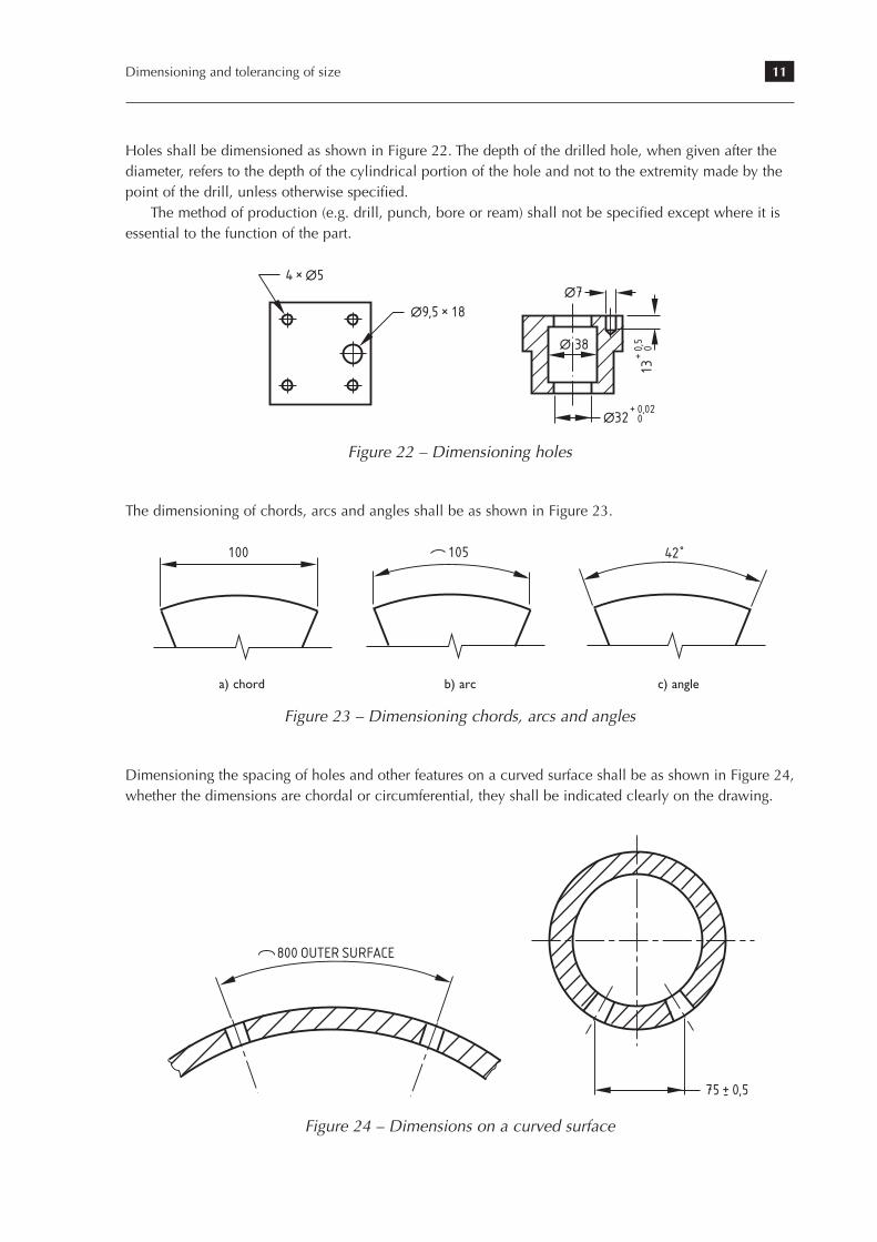
Holes shall be dimensioned as shown in Figure 22. The depth of the drilled hole, when given after the diameter, refers to the depth of the cylindrical portion of the hole and not to the extremity made by the point of the drill, unless otherwise specified.
The method of production (e.g. drill, punch, bore or ream) shall not be specified except where it is essential to the function of the part.
6. Dimensioning of technical drawings
6.7.4 Holes
Holes are dimensioned as shown in Figure 80. The depth of the drilled hole, when
given after the diameter, refers to the depth of the cylindrical portion of the hole and
not to the extremity made by the point of the drill, unless otherwise specified.
6.7.5 Chords, arcs and angles
The dimensioning of chords, arcs and angles should be as shown in Figure 81.
79
∆32 0
38
+ 0,02
13
0+
0,5
∆9,5 × 18
4 × ∆5∆7
∆
Figure 80: Dimensioning
holes
Teacher’s note: the method of production (e.g. drill, punch, bore or ream) should
not be specified except where it is essential to the function of the drawing.
100 105
42
(a) Chord (b) Arc
(c) Angle
Figure 81: Dimensioning
chords, arcs and angles
Figure 22 – Dimensioning holes
The dimensioning of chords, arcs and angles shall be as shown in Figure 23.
6. Dimensioning of technical drawings
6.7.4 Holes
Holes are dimensioned as shown in Figure 80. The depth of the drilled hole, when
given after the diameter, refers to the depth of the cylindrical portion of the hole and
not to the extremity made by the point of the drill, unless otherwise specified.
6.7.5 Chords, arcs and angles
The dimensioning of chords, arcs and angles should be as shown in Figure 81.
79
∆32 0
38
+ 0,02
13
0+
0,5
∆9,5 × 18
4 × ∆5∆7
∆
Figure 80: Dimensioning
holes
Teacher’s note: the method of production (e.g. drill, punch, bore or ream) should
not be specified except where it is essential to the function of the drawing.
100 105
42
(a) Chord (b) Arc
(c) Angle
Figure 81: Dimensioning
chords, arcs and angles
a) chord b) arc c) angle
Figure 23 – Dimensioning chords, arcs and angles
Dimensioning the spacing of holes and other features on a curved surface shall be as shown in Figure 24, whether the dimensions are chordal or circumferential, they shall be indicated clearly on the drawing.
80
6.7.6 Curved surfaces
When dimensioning the spacing of holes and other features on a curved surface,
whether the dimensions are chordal or circumferential, they are to be indicated clearly
on the drawing, as shown in Figure 82.
6.8 Dimensioning screw threads and threadedparts
6.8.1 Designation of ISO metric screw threads
ISO metric screw threads are designated in accordance with BS EN ISO 6410-1, which
specifies that the designation should indicate the thread system, nominal diameter
and the thread tolerance class. If necessary, the pitch should also be indicated;
however, when designating metric coarse threads, the pitch is generally omitted.
Drawing practice
800 OUTER SURFACE
75 + 0,5-
Figure 82: Dimensions on
a curved surface
Figure 24 – Dimensions on a curved surface
12 The Essential Guide to Technical Product Specification: Engineering Drawing
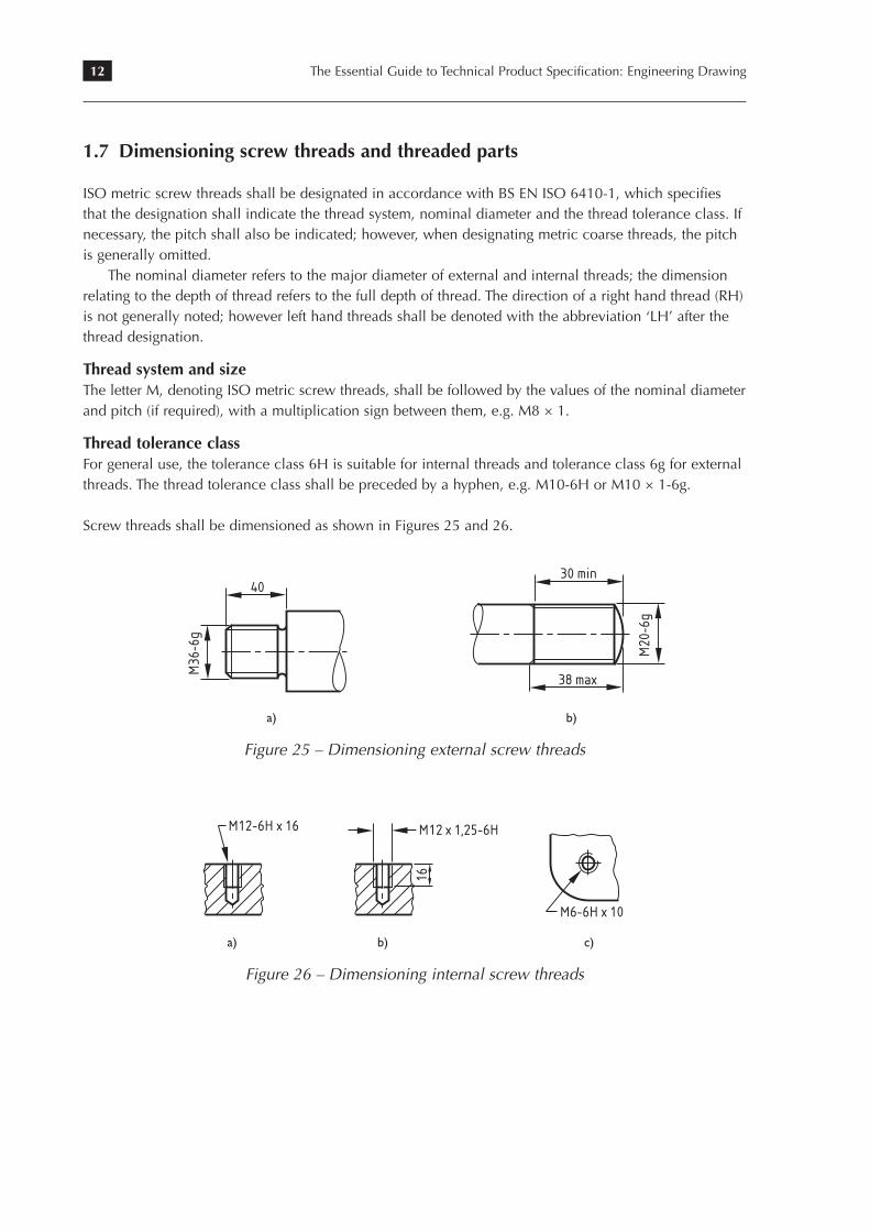
1.7 Dimensioning screw threads and threaded parts
ISO metric screw threads shall be designated in accordance with BS EN ISO 6410-1, which specifies that the designation shall indicate the thread system, nominal diameter and the thread tolerance class. If necessary, the pitch shall also be indicated; however, when designating metric coarse threads, the pitch is generally omitted.
The nominal diameter refers to the major diameter of external and internal threads; the dimension relating to the depth of thread refers to the full depth of thread. The direction of a right hand thread (RH) is not generally noted; however left hand threads shall be denoted with the abbreviation ‘LH’ after the thread designation.
Thread system and sizeThe letter M, denoting ISO metric screw threads, shall be followed by the values of the nominal diameter and pitch (if required), with a multiplication sign between them, e.g. M8 × 1.
Thread tolerance classFor general use, the tolerance class 6H is suitable for internal threads and tolerance class 6g for external threads. The thread tolerance class shall be preceded by a hyphen, e.g. M10-6H or M10 × 1-6g.
Screw threads shall be dimensioned as shown in Figures 25 and 26.
6. Dimensioning of technical drawings
6.8.2 Thread system and size
The letter M, denoting ISO metric screw threads, is followed by the values of the
nominal diameter and pitch (if required), with a multiplication sign between them,
e.g. M8 × 1.
6.8.3 Thread tolerance class
For general use, the tolerance class 6H is suitable for internal threads and tolerance
class 6g for external threads. The thread tolerance class is preceded by a hyphen, e.g.
M10-6H or M10 × 1-6g.
Screw threads are dimensioned as shown in Figures 83 and 84.
81
40
M36
-6g
(a)(b)
30 minfull thread
38 max
M20
-6g
Figure 83: Dimensioning
external screw threads
(a) (b)
(c)
M12-6H x 1615 minfull thread
M12 x 1,25-6H
16
M6-6H x 1020 min full thread28 max including run-out
Figure 84: Dimensioning
internal screw threads
a) b)
Figure 25 – Dimensioning external screw threads
6. Dimensioning of technical drawings
6.8.2 Thread system and size
The letter M, denoting ISO metric screw threads, is followed by the values of the
nominal diameter and pitch (if required), with a multiplication sign between them,
e.g. M8 × 1.
6.8.3 Thread tolerance class
For general use, the tolerance class 6H is suitable for internal threads and tolerance
class 6g for external threads. The thread tolerance class is preceded by a hyphen, e.g.
M10-6H or M10 × 1-6g.
Screw threads are dimensioned as shown in Figures 83 and 84.
81
40
M36
-6g
(a)(b)
30 minfull thread
38 max
M20
-6g
Figure 83: Dimensioning
external screw threads
(a) (b)
(c)
M12-6H x 1615 minfull thread
M12 x 1,25-6H
16
M6-6H x 1020 min full thread28 max including run-out
Figure 84: Dimensioning
internal screw threads
a) b) c)
Figure 26 – Dimensioning internal screw threads
6. Dimensioning of technical drawings
6.8.2 Thread system and size
The letter M, denoting ISO metric screw threads, is followed by the values of the
nominal diameter and pitch (if required), with a multiplication sign between them,
e.g. M8 × 1.
6.8.3 Thread tolerance class
For general use, the tolerance class 6H is suitable for internal threads and tolerance
class 6g for external threads. The thread tolerance class is preceded by a hyphen, e.g.
M10-6H or M10 × 1-6g.
Screw threads are dimensioned as shown in Figures 83 and 84.
81
40
M36
-6g
(a)(b)
30 minfull thread
38 max
M20
-6g
Figure 83: Dimensioning
external screw threads
(a) (b)
(c)
M12-6H x 1615 minfull thread
M12 x 1,25-6H
16
M6-6H x 1020 min full thread28 max including run-out
Figure 84: Dimensioning
internal screw threads
13Dimensioning and tolerancing of size
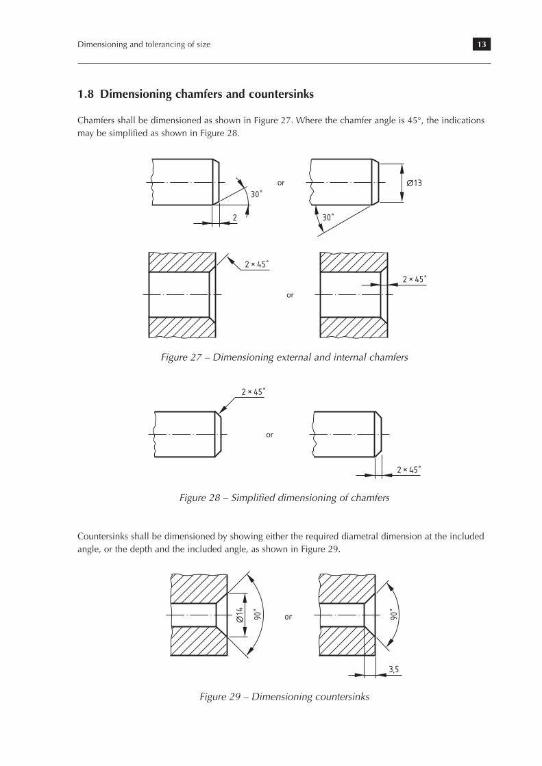
1.8 Dimensioning chamfers and countersinks
Chamfers shall be dimensioned as shown in Figure 27. Where the chamfer angle is 45°, the indications may be simplified as shown in Figure 28.
13. Dimensioning from a common feature
Note. Methods of production (e.g. ‘drill’, ‘punch’, ‘bore’, ‘ream’) should not be
specified, except where they are essential to the function.
13.7 Chamfers and countersinks
Chamfers should be dimensioned as shown in Figure 103. Where the chamfer angle is
45°, the indications may be simplified as shown in Figures 104 and 105.
87
∆32 0
38
+ 0,02
13
0+
0,5
∆9,5 × 18
4 × ∆5∆7
∆
Figure 102: Hole
dimensioning
2
30 ˚
30 ˚
∆13or
Figure 103: Chamfer
dimensioning
2 × 45 ˚
2 × 45 ˚
or
Figure 104: 45° chamfers
simplified
2 × 45 ˚
2 × 45 ˚
or
Figure 105: Dimensioning
internal chamfers
113
Figure 27 – Dimensioning external and internal chamfers
13. Dimensioning from a common feature
Note. Methods of production (e.g. ‘drill’, ‘punch’, ‘bore’, ‘ream’) should not be
specified, except where they are essential to the function.
13.7 Chamfers and countersinks
Chamfers should be dimensioned as shown in Figure 103. Where the chamfer angle is
45°, the indications may be simplified as shown in Figures 104 and 105.
87
∆32 0
38
+ 0,02
13
0+
0,5
∆9,5 × 18
4 × ∆5∆7
∆
Figure 102: Hole
dimensioning
2
30 ˚
30 ˚
∆13or
Figure 103: Chamfer
dimensioning
2 × 45 ˚
2 × 45 ˚
or
Figure 104: 45° chamfers
simplified
2 × 45 ˚
2 × 45 ˚
or
Figure 105: Dimensioning
internal chamfers
113
Figure 28 – Simplified dimensioning of chamfers
Countersinks shall be dimensioned by showing either the required diametral dimension at the included angle, or the depth and the included angle, as shown in Figure 29.
88
Countersinks are dimensioned by showing either the required diametral dimension at
the included angle, or the depth and the included angle (see Figure 106).
13.8 Other indications
The use of reference letters in conjunction with an explanatory note or table can also be
used as a simplified method of dimensioning. This method avoids the use of long
leader lines and the need to repeat common data (see Figure 107).
Dimensioning of symmetrical parts using partial views is another simplified method of
presentation, as illustrated in Figure 108. The dimension lines that need to cross the
axis of symmetry are shown slightly extended beyond the axis of symmetry.
Where there is a need for more than one part to be drawn in close proximity, such as in
an assembly, the relative dimensions of each part should be presented as separately as
possible to aid clarity (see Figure 109).
Engineering drawing practice
3,5
∆14 90
˚
or 90 ˚
Figure 106: Dimensioning
countersinks
A
B
AB
A
B
A = 3 × ∆12B = 3 × ∆10
Figure 107: Dimensioning
with reference letters
114
Figure 29 – Dimensioning countersinks
14 The Essential Guide to Technical Product Specification: Engineering Drawing
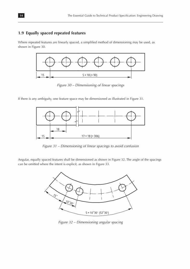
1.9 Equally spaced repeated features
Where repeated features are linearly spaced, a simplified method of dimensioning may be used, as shown in Figure 30.
84
13.5 Equally spaced repeated features
Where repeated features are linearly spaced, a simplified method of dimensioning may
be used, as illustrated in Figure 95.
If there is any ambiguity, one feature space may be dimensioned as illustrated in
Figure 96.
Angular, equally spaced features may be dimensioned as illustrated in Figure 97.
The angles of the spacings may be omitted when the intent is evident, as shown in
Figure 98.
Circular spaced features may be dimensioned indirectly by specifying the number of
common features, as illustrated in Figure 99.
Engineering drawing practice
50
16
R
Figure 94: Indicating a
radius where its value has
been derived from other
dimensions
15 5 × 18 (= 90)
Figure 95: Dimensioning
of linear spacings
15 17 × 18 (= 306)
18
Figure 96: Dimensioning
of linear spacings to avoid
confusion
110
Figure 30 – Dimensioning of linear spacings
If there is any ambiguity, one feature space may be dimensioned as illustrated in Figure 31.
84
13.5 Equally spaced repeated features
Where repeated features are linearly spaced, a simplified method of dimensioning may
be used, as illustrated in Figure 95.
If there is any ambiguity, one feature space may be dimensioned as illustrated in
Figure 96.
Angular, equally spaced features may be dimensioned as illustrated in Figure 97.
The angles of the spacings may be omitted when the intent is evident, as shown in
Figure 98.
Circular spaced features may be dimensioned indirectly by specifying the number of
common features, as illustrated in Figure 99.
Engineering drawing practice
50
16
R
Figure 94: Indicating a
radius where its value has
been derived from other
dimensions
15 5 × 18 (= 90)
Figure 95: Dimensioning
of linear spacings
15 17 × 18 (= 306)
18
Figure 96: Dimensioning
of linear spacings to avoid
confusion
110
Figure 31 – Dimensioning of linear spacings to avoid confusion
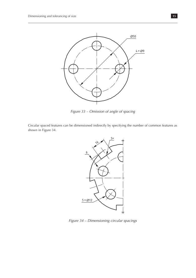
Angular, equally spaced features shall be dimensioned as shown in Figure 32. The angle of the spacings can be omitted where the intent is explicit, as shown in Figure 33.
13. Dimensioning from a common feature
85
5 × 10 ˚ 30' (52 ˚ 30')
10 ˚ 30'
15 ˚
Figure 97: Dimensioning
of angular spacings
∆50
4 × ∆9
Figure 98: The omission of
angles of spacings to avoid
confusion
5 × ∆12
5×
16
6
Figure 99: Dimensioning
circular spacings
111
Figure 32 – Dimensioning angular spacing
15Dimensioning and tolerancing of size
13. Dimensioning from a common feature
85
5 × 10 ˚ 30' (52 ˚ 30')
10 ˚ 30'
15 ˚
Figure 97: Dimensioning
of angular spacings
∆50
4 × ∆9
Figure 98: The omission of
angles of spacings to avoid
confusion
5 × ∆12
5×
16
6
Figure 99: Dimensioning
circular spacings
111
Figure 33 – Omission of angle of spacing
Circular spaced features can be dimensioned indirectly by specifying the number of common features as shown in Figure 34.
13. Dimensioning from a common feature
85
5 × 10 ˚ 30' (52 ˚ 30')
10 ˚ 30'
15 ˚
Figure 97: Dimensioning
of angular spacings
∆50
4 × ∆9
Figure 98: The omission of
angles of spacings to avoid
confusion
5 × ∆12
5×
16
6
Figure 99: Dimensioning
circular spacings
111
Figure 34 – Dimensioning circular spacings
16 The Essential Guide to Technical Product Specification: Engineering Drawing
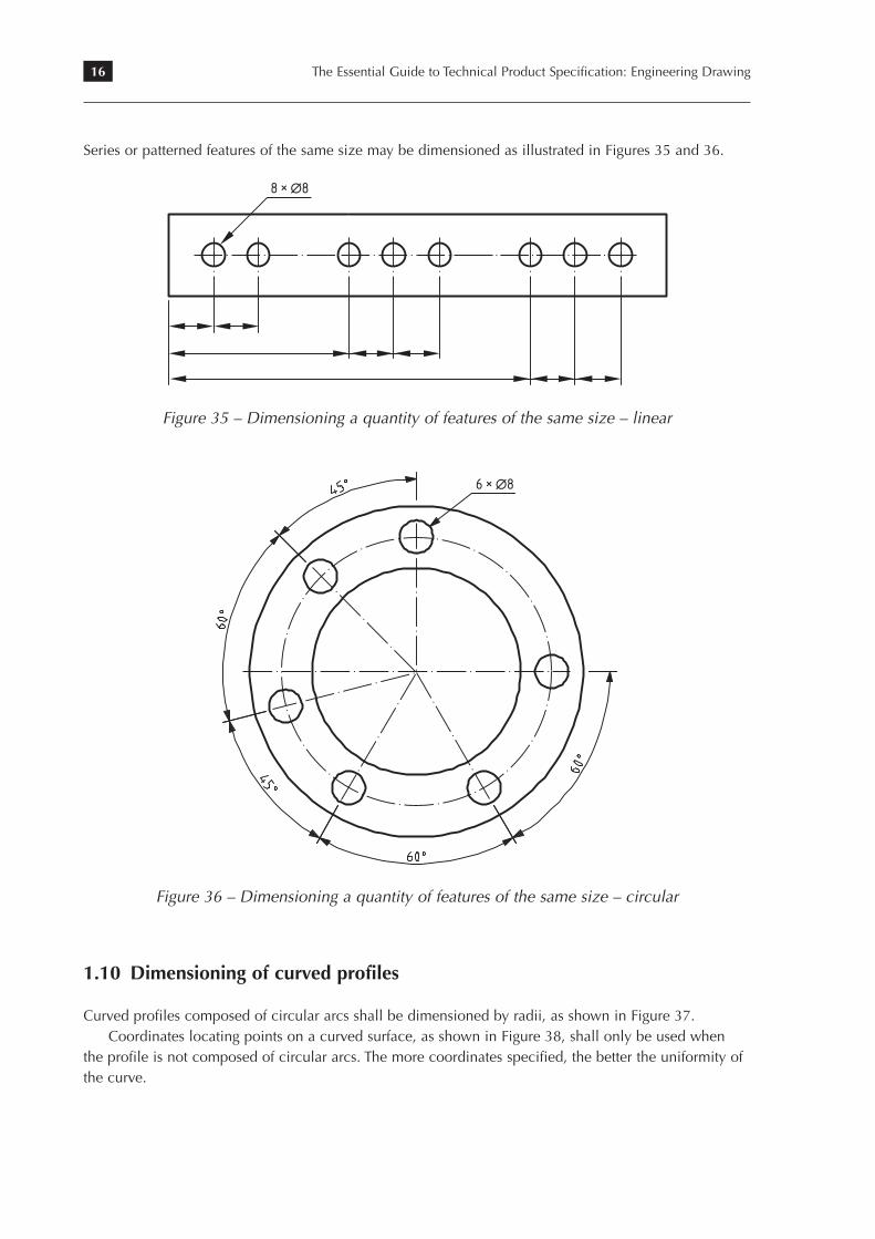
Series or patterned features of the same size may be dimensioned as illustrated in Figures 35 and 36.
86
Series or patterned features of the same size may be dimensioned as illustrated in
Figures 100 and 101.
13.6 Holes
Holes are dimensioned as shown in Figure 102. The depth of the drilled hole, when
given after the diameter, shall refer to the depth of the cylindrical portion of the hole
and not to the extremity made by the point of the drill, unless otherwise specified.
Engineering drawing practice
8 × ∆8Figure 100: Defining a
quantity of elements of the
same size: linear
6 × ∆8Figure 101: Defining a
quantity of elements of the
same size: circular
112
Figure 35 – Dimensioning a quantity of features of the same size – linear
86
Series or patterned features of the same size may be dimensioned as illustrated in
Figures 100 and 101.
13.6 Holes
Holes are dimensioned as shown in Figure 102. The depth of the drilled hole, when
given after the diameter, shall refer to the depth of the cylindrical portion of the hole
and not to the extremity made by the point of the drill, unless otherwise specified.
Engineering drawing practice
8 × ∆8Figure 100: Defining a
quantity of elements of the
same size: linear
6 × ∆8Figure 101: Defining a
quantity of elements of the
same size: circular
112
Figure 36 – Dimensioning a quantity of features of the same size – circular
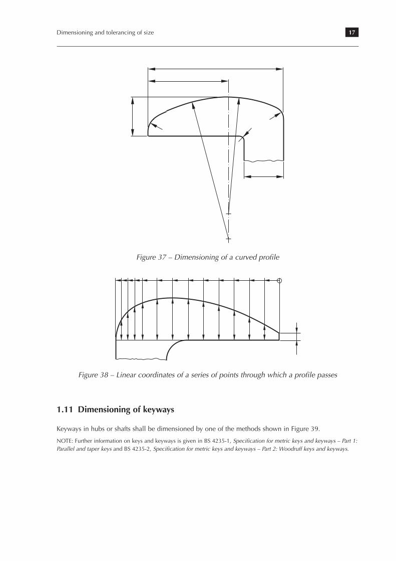
1.10 Dimensioning of curved profiles
Curved profiles composed of circular arcs shall be dimensioned by radii, as shown in Figure 37.Coordinates locating points on a curved surface, as shown in Figure 38, shall only be used when
the profile is not composed of circular arcs. The more coordinates specified, the better the uniformity of the curve.
17Dimensioning and tolerancing of size
13. Dimensioning from a common feature
Levels for contour lines should be located on the upper side of the contour line and
should be given as follows:
Elevation datums to be used when setting out dimensions should be shown as follows:
13.13 Dimensioning of curved profiles
Profiles may be dimensioned by either of the methods described in Sections 12.8 and
12.9.
Curved profiles composed of circular arcs should be dimensioned by radii, as illustrated
in Figure 118.
93
Contour line
Original ground level no longer valid
49,000
FIX +0,000
Figure 118: The
dimensioning of a curved
profile
119
Figure 37 – Dimensioning of a curved profile
94
Coordinates locating points on a curved surface, as illustrated in Figure 119, should
only be used when the profile is not composed of circular arcs. The more coordinates
specified, the better the uniformity of the curve.
Figure 120 illustrates a method of specifying a cam profile in association with a
follower. The follower is indicated by a long-dashed double-dotted narrow line type
05.1.1 (see Table 1).
Engineering drawing practice
Figure 119: Linear
coordinates of a series of
points through which a
profile passes
a
0 ˚
25 Follower
b
ba
0 ˚
50 ˚
20 ˚
52,5 ˚
40 ˚
57 ˚
60 ˚
63,5 ˚
80 ˚
70 ˚
100 ˚
74,5 ˚
230 ˚
75 ˚
260 ˚
70 ˚
280 ˚
65 ˚
300 ˚
59,5 ˚
320 ˚
55 ˚
340 ˚
52˚
120 ˚ to 210 ˚
76 ˚
Figure 120: Specifying
dimensions in association
with a follower
120
Figure 38 – Linear coordinates of a series of points through which a profile passes
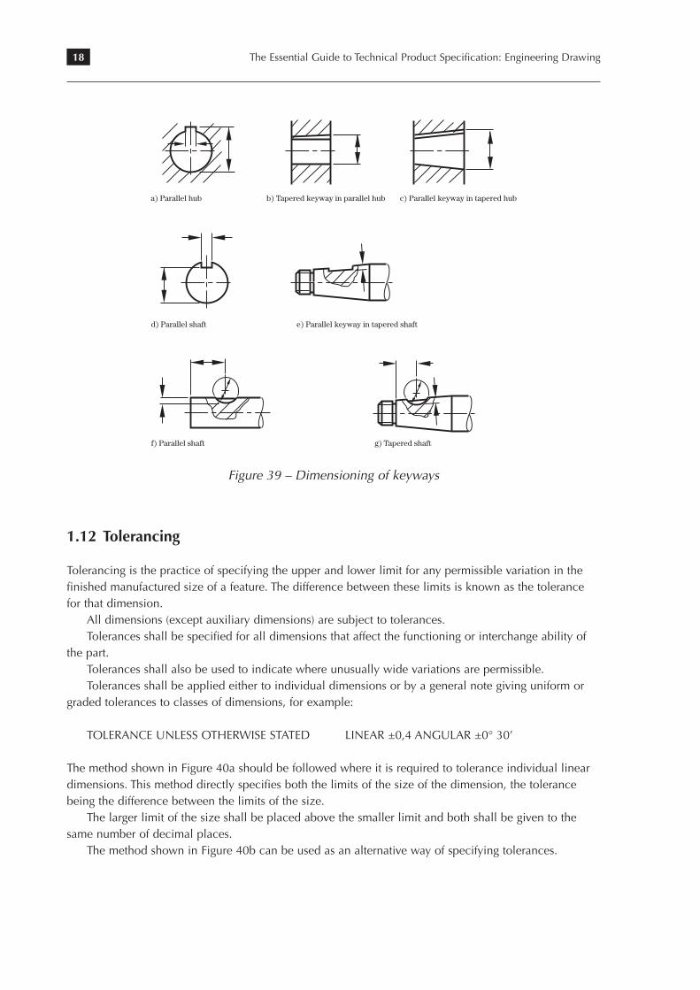
1.11 Dimensioning of keyways
Keyways in hubs or shafts shall be dimensioned by one of the methods shown in Figure 39.
NOTE: Further information on keys and keyways is given in BS 4235-1, Specification for metric keys and keyways – Part 1: Parallel and taper keys and BS 4235-2, Specification for metric keys and keyways – Part 2: Woodruff keys and keyways.
18 The Essential Guide to Technical Product Specification: Engineering Drawing
© BSI 2006 • 21
BS 8888:2006
16.3 Presentation of decimals
16.3.1 Decimal marker
The decimal marker shall be a comma.
16.3.2 Non-indicated decimals in tolerances
Non-indicated decimals in a tolerance indication shall be taken as zeros e.g. 0,2 is the same as 0,20000000000….
COMMENTARY AND RECOMMENDATIONS ON 16.3
It is recommended that each group of three digits, counting from the decimal marker to the left and to the right, be separated from other digits by a small space (e.g. 12 345,067 8). In view of the requirement of 16.3.1, the use of a comma or a point for this purpose is deprecated, i.e. it is further recommended that separation of items in lists be effected by the use of a semi-colon. (See BS ISO 31-0, Specification for quantities, units and symbols – Part 0: General principles.)
16.4 KeywaysKeyways in hubs or shafts shall be dimensioned by one of the methods shown in Figure 5.
NOTE Further information on keys and keyways is given in BS 4235-1, Specification for metric keys and keyways – Part 1: Parallel and taper keys, and BS 4235-2, Specification for metric keys and keyways – Part 2: Woodruff keys and keyways.
Figure 5 Dimensioning of keyways
a) Parallel hub b) Tapered keyway in parallel hub
d) Parallel shaft
f) Parallel shaft g) Tapered shaft
e) Parallel keyway in tapered shaft
c) Parallel keyway in tapered hub
Lice
nsed
Cop
y: J
enny
Cra
nwel
l, B
ritis
h S
tand
ards
Inst
itutio
n, 3
1/07
/200
9 17
:12,
Unc
ontr
olle
d C
opy,
(c)
BS
I
Figure 39 – Dimensioning of keyways
1.12 Tolerancing
Tolerancing is the practice of specifying the upper and lower limit for any permissible variation in the finished manufactured size of a feature. The difference between these limits is known as the tolerance for that dimension.
All dimensions (except auxiliary dimensions) are subject to tolerances.Tolerances shall be specified for all dimensions that affect the functioning or interchange ability of
the part.Tolerances shall also be used to indicate where unusually wide variations are permissible.Tolerances shall be applied either to individual dimensions or by a general note giving uniform or
graded tolerances to classes of dimensions, for example:
TOLERANCE UNLESS OTHERWISE STATED LINEAR ±0,4 ANGULAR ±0° 30’
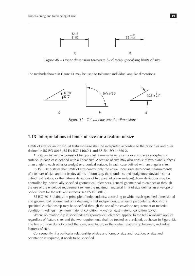
The method shown in Figure 40a should be followed where it is required to tolerance individual linear dimensions. This method directly specifies both the limits of the size of the dimension, the tolerance being the difference between the limits of the size.
The larger limit of the size shall be placed above the smaller limit and both shall be given to the same number of decimal places.
The method shown in Figure 40b can be used as an alternative way of specifying tolerances.
19Dimensioning and tolerancing of size
82
6.9 Tolerancing
6.9.1 General
Tolerancing is the practice of specifying the upper and lower limit for any permissible
variations in the finished manufactured size of a feature. The difference between these
limits is known as the tolerance for that dimension. All dimensions (except auxiliary
dimensions) are subject to tolerances. Tolerances should be specified for all dimensions
that affect the functioning or interchange ability of the part. Tolerances should also be
used to indicate where unusually wide variations are permissible.
6.9.2 Application of tolerances
Tolerances should be applied either to individual dimensions or by a general note
giving uniform or graded tolerances to classes of dimensions, for example:
TOLERANCE UNLESS OTHERWISE STATED
LINEAR ±0,4 ANGULAR ±0° 30¢
6.9.3 Tolerancing of individual linear dimensions
The method shown in Figure 85 is recommended where it is required to tolerance indi-
vidual linear dimensions. This method directly specifies both the limits of the size of the
dimension, the tolerance being the difference between the limits of the size.
Drawing practice
Teacher’s note: it is unlikely that most students will need to dimension threaded
parts to the degree of detail shown here. However, as a teaching point it is worth
explaining to students the fine details (e.g. tolerancing values, maximum and
minimum thread lengths) that are invariably required in engineering drawings
supplied by the designer to the manufacturer.
32,1531,80
Figure 85: Linear
dimension tolerance by
specifying limits of size
directly
32+0,15-0,20
Dat
e:
15/0
6/20
09B
SI/P
M:
Jen
ny C
ranw
ell
Mod
ific
atio
ns:
Appr
oval
of i
ssue
Oper
ator
: Nor
a D
awso
n (7
769)
Dep
artm
ent:
Mod
ific
atio
ns:
Dat
e:Si
gnat
ure:
File name: 2008-01133_40b.epsBIP 2155
a) b)
Figure 40 – Linear dimension tolerance by directly specifying limits of size
The methods shown in Figure 41 may be used to tolerance individual angular dimensions.
6. Dimensioning of technical drawings
The larger limit of the size is placed above the smaller limit, and both are given to the
same number of decimal places.
6.9.4 Tolerancing of individual angular dimensions
The methods shown in Figure 86 may be used to tolerance individual angular dimensions.
6.10 Summary
This chapter has covered those parts of the standards that deal with dimensioning and
tolerancing which are likely to be of use to Design and Technology teachers and their
students in schools and colleges. The key points are as follows.
] The general principles of dimensioning as set out in BS 8888:2006 should always
be followed if effective communication between the designer, manufacturer and
end user is to be established and maintained.
] Functional dimensions are those that directly affect the function of the product.
] All dimensions except auxiliary dimensions are subject to tolerancing.
] The decimal marker is represented by a comma not a point.
] Groups of numerals to the left and right of the decimal marker should be divided
up into groups of three, counting from the decimal marker, and a full space, not a
comma, left between them.
83
Figure 86: Tolerancing
angular dimensions30 30'30 0'
90 ± 0 30' 30,5 ± 0,1
0
Relevant standards Title
BS EN ISO 1660 Technical drawings — Dimensioning and
tolerancing of profiles
BS ISO 129-1 Technical drawings — Indication of dimensions
and tolerances — Part 1: General principles
(a) (b) (c) a) b) c)
Figure 41 – Tolerancing angular dimensions
1.13 Interpretations of limits of size for a feature-of-size
Limits of size for an individual feature-of-size shall be interpreted according to the principles and rules defined in BS ISO 8015, BS EN ISO 14660-1 and BS EN ISO 14660-2.
A feature-of-size may consist of two parallel plane surfaces, a cylindrical surface or a spherical surface, in each case defined with a linear size. A feature-of-size may also consist of two plane surfaces at an angle to each other (a wedge) or a conical surface, in each case defined with an angular size.
BS ISO 8015 states that limits of size control only the actual local sizes (two-point measurements) of a feature-of-size and not its deviations of form (e.g. the roundness and straightness deviations of a cylindrical feature, or the flatness deviations of two parallel plane surfaces). Form deviations may be controlled by individually specified geometrical tolerances, general geometrical tolerances or through the use of the envelope requirement (where the maximum material limit of size defines an envelope of perfect form for the relevant surfaces; see BS ISO 8015).
BS ISO 8015 defines the principle of independency, according to which each specified dimensional and geometrical requirement on a drawing is met independently, unless a particular relationship is specified. A relationship may be specified through the use of the envelope requirement or material condition modifiers maximum material condition (MMC) or least material condition (LMC).
Where no relationship is specified, any geometrical tolerance applied to the feature-of-size applies regardless of feature size, and the two requirements shall be treated as unrelated, as shown in Figure 42. The limits of size do not control the form, orientation, or the spatial relationship between, individual features-of-size.
Consequently, if a particular relationship of size and form, or size and location, or size and orientation is required, it needs to be specified.
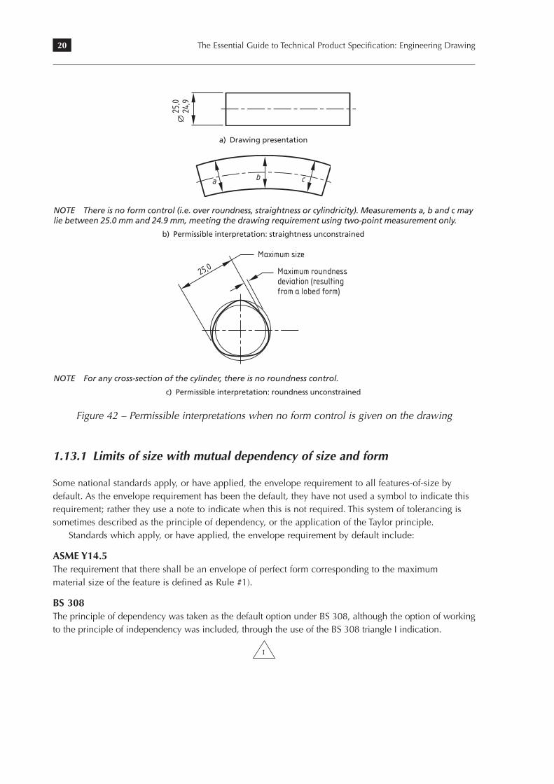
20 The Essential Guide to Technical Product Specification: Engineering DrawingBS 8888:2008
16 • © BSI 2008
BritiSh Standard
Figure 3 Permissible interpretations when no form control is given on the drawing
25,0
24,9
a) drawing presentation
a b c
NOTE There is no form control (i.e. over roundness, straightness or cylindricity). Measurements a, b and c may lie between 25.0 mm and 24.9 mm, meeting the drawing requirement using two-point measurement only.
b) Permissible interpretation: straightness unconstrained
25,0
Maximum size
Maximum roundness deviation (resultingfrom a lobed form)
NOTE For any cross-section of the cylinder, there is no roundness control.
c) Permissible interpretation: roundness unconstrained
15.1.2 Limits of size with mutual dependency of size and formCOMMENTARY AND RECOMMENDATIONS ON 15.1.2
Some national standards apply, or have applied, the Envelope Requirement to all features-of-size by default. As the Envelope Requirement has been the default, they have not used a symbol to indicate this requirement; rather they use a note to indicate when this is not required. This system of tolerancing is sometimes described as the Principle of Dependency, or the application of the Taylor Principle.
Standards which apply, or have applied, the Envelope Requirement by default include:
ASME Y14.5 (the requirement that there is an envelope of perfect form corresponding to the Maximum Material Size of the feature is defined as Rule #1).
BS 308 (the Principle of Dependency was taken as the default option under BS 308, although the option of working to the Principle of Independency was included, through the use of the BS 308 triangle I indication):
BS 8888 I
BS 8888 prior to the 2004 revision (the Principle of Dependency was taken as the default option under BS 8888:2000 and BS 8888:2002, although the option of working to the Principle of Independency was included, through the use of the BS 8888 triangle I indication).
Figure 42 – Permissible interpretations when no form control is given on the drawing
1.13.1 Limits of size with mutual dependency of size and form
Some national standards apply, or have applied, the envelope requirement to all features-of-size by default. As the envelope requirement has been the default, they have not used a symbol to indicate this requirement; rather they use a note to indicate when this is not required. This system of tolerancing is sometimes described as the principle of dependency, or the application of the Taylor principle.
Standards which apply, or have applied, the envelope requirement by default include:
ASME Y14.5The requirement that there shall be an envelope of perfect form corresponding to the maximummaterial size of the feature is defined as Rule #1).
BS 308The principle of dependency was taken as the default option under BS 308, although the option of working to the principle of independency was included, through the use of the BS 308 triangle I indication.
BS 8888 I
21Dimensioning and tolerancing of size
BS 8888Prior to the 2004 revision; the principle of dependency was taken as the default option under BS 8888:2000 and BS 8888:2002, although the option of working to the principle of independency was included, through the use of the BS 8888 triangle I indication.
BS 8888:2004 and BS 8888:2006the principle of dependency could be explicitly invoked through the use of the BS 8888 triangle D indication.
BS 8888 D
As the interaction between the envelope requirement and individual geometrical tolerances is not always fully defined within the ISO system, and as the application of the envelope requirement by default to all features-of-size is not formally supported within the ISO system, the use of the principle of dependency is no longer recommended.
1.14 Datum surfaces and functional requirements
Functional dimensions shall be expressed directly on the drawing, as shown in Figure 1. The application of this principle will result in the selection of reference features on the basis of the function of the product and the method of locating it in any assembly of which it may form a part.
If any reference feature other than one based on the function of the product is used, finer tolerances will be necessary to meet the functional requirement, which in turn will increase the cost of producing the product, as shown in Figure 43 on page 22.
1.15 Relevant standards
BS EN ISO 1660, Technical drawings — Dimensioning and tolerancing of profilesBS ISO 129-1, Technical drawings — Indication of dimensions and tolerances — Part 1:
General principlesBS ISO 3040, Technical drawings — Dimensioning and tolerancing — ConesBS ISO 10579, Technical drawings — Dimensioning and tolerancing — Non-rigid partsBS ISO 406, Technical drawings — Tolerancing of linear and angular dimensionsBS EN 22768-1, General tolerances — Part 1: Tolerances for linear and angular dimensions without
individual tolerance indicationsBS 4235-1, Specification for metric keys and keyways — Part 1: Parallel and taper keysBS 4235-2, Specification for metric keys and keyways — Part 2: Woodruff keys and keywaysBS ISO 8015, Technical drawings — Fundamental tolerancing principleBS EN ISO 14660-1, Geometrical Product Specifications (GPS) — Geometrical features — Part 1:
General terms and definitionsBS EN ISO 14660-2, Geometrical Product Specifications (GPS) — Geometrical features — Part 2:
Extracted median line of a cylinder and a cone, extracted median surface, local size of an extracted feature
PP 8888-2, Engineering drawing practice: a guide for further and higher education to BS 8888:2006, Technical product specification (TPS)
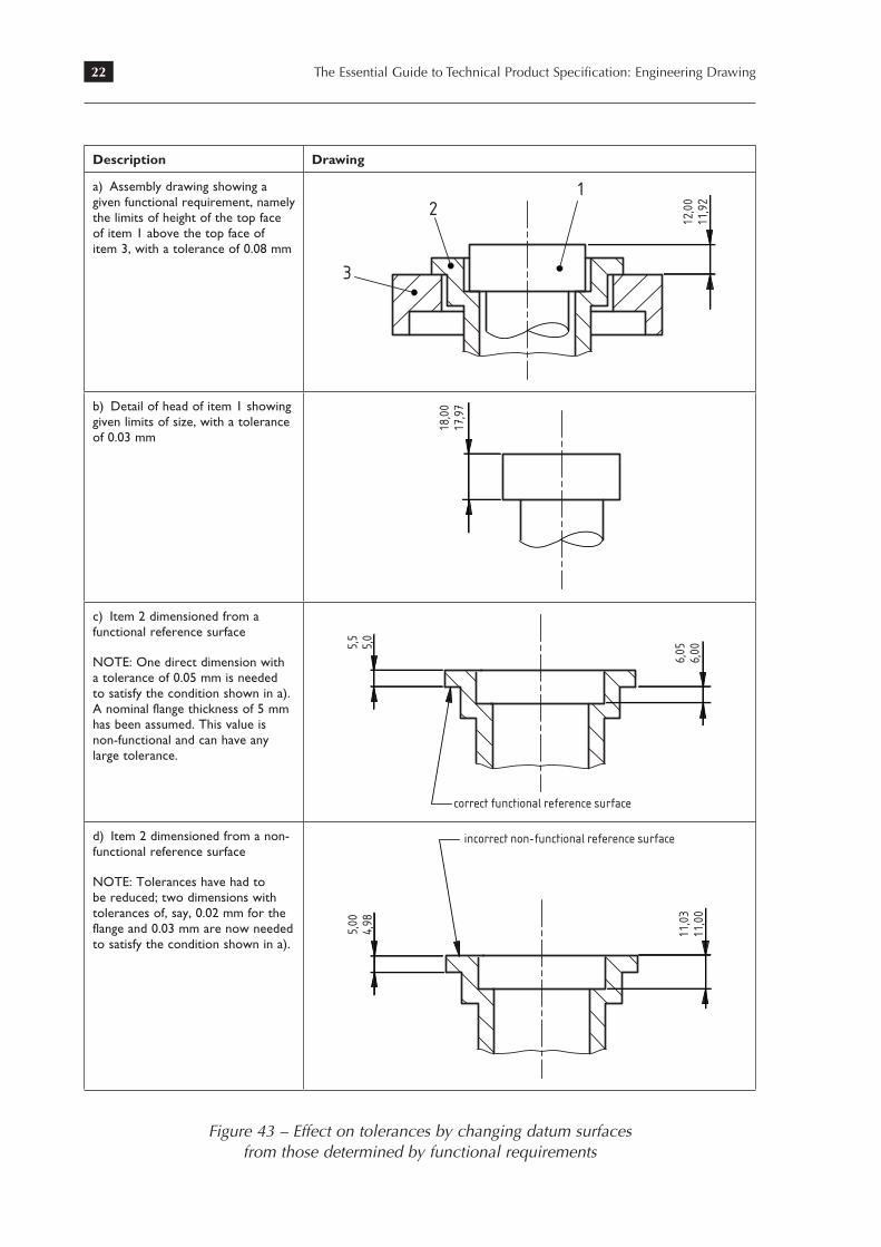
22 The Essential Guide to Technical Product Specification: Engineering Drawing
Description Drawing
a) Assembly drawing showing a given functional requirement, namely the limits of height of the top face of item 1 above the top face of item 3, with a tolerance of 0.08 mm
3
21
12,0
011
,92
Dat
e:
15/0
6/20
09B
SI/P
M:
Jen
ny C
ranw
ell
Mod
ific
atio
ns:
Appr
oval
of i
ssue
Oper
ator
: Nor
a D
awso
n (7
769)
Dep
artm
ent:
Mod
ific
atio
ns:
Dat
e:Si
gnat
ure:
File name: 2008-01133_43a.epsBIP 2155
b) Detail of head of item 1 showing given limits of size, with a tolerance of 0.03 mm
18,0
017
,97
Dat
e:
15/0
6/20
09B
SI/P
M:
Jen
ny C
ranw
ell
Mod
ific
atio
ns:
Appr
oval
of i
ssue
Oper
ator
: Nor
a D
awso
n (7
769)
Dep
artm
ent:
Mod
ific
atio
ns:
Dat
e:Si
gnat
ure:
File name: 2008-01133_43b.epsBIP 2155
c) Item 2 dimensioned from a functional reference surface
NOTE: One direct dimension with a tolerance of 0.05 mm is needed to satisfy the condition shown in a). A nominal flange thickness of 5 mm has been assumed. This value is non-functional and can have any large tolerance.
6,05
6,005,
55,
0
correct functional reference surface
Dat
e:
15/0
6/20
09B
SI/P
M:
Jen
ny C
ranw
ell
Mod
ific
atio
ns:
Appr
oval
of i
ssue
Oper
ator
: Nor
a D
awso
n (7
769)
Dep
artm
ent:
Mod
ific
atio
ns:
Dat
e:Si
gnat
ure:
File name: 2008-01133_43c.epsBIP 2155
d) Item 2 dimensioned from a non-functional reference surface
NOTE: Tolerances have had to be reduced; two dimensions with tolerances of, say, 0.02 mm for the flange and 0.03 mm are now needed to satisfy the condition shown in a).
11,0
311
,00
5,00
4,98
incorrect non-functional reference surface
Dat
e:
15/0
6/20
09B
SI/P
M:
Jen
ny C
ranw
ell
Mod
ific
atio
ns:
Appr
oval
of i
ssue
Oper
ator
: Nor
a D
awso
n (7
769)
Dep
artm
ent:
Mod
ific
atio
ns:
Dat
e:Si
gnat
ure:
File name: 2008-01133_43d.epsBIP 2155
Figure 43 – Effect on tolerances by changing datum surfaces from those determined by functional requirements