Embed Size (px)
Citation preview
Abstract—facility layout problems (FLPs) are common
problem in several manufacturing industries because FLPs have a great impact on production operations. Efficient manufacturing facility layout design could lead to lower manufacturing costs. Therefore, many sub problems should be addressed and considered from design stage. This research proposes a new framework for mix-model assembly line (MAL) manufacturing facility design. Four key objectives to evaluate layout performance and synchronize designs’ evaluation processes in order to create optimized manufacturing facility layout are also discussed.
Index Terms— facility layout design, material supply design, automotive, shop design, material flow path design
I. INTRODUCTION ANUFACTURING planning is one of the key processes to determine how companies would
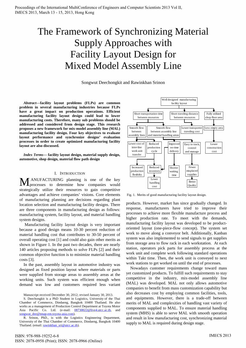
strategically utilize their resources to gain competitive advantages and achieve companies’ visions. Core elements of manufacturing planning are decisions regarding plant location selection and manufacturing facility designs. There are three components in manufacturing design as follows: manufacturing system, facility layout, and material handling system designs. Manufacturing facility layout design is very important because a good design means 10-30 percent reduction of material handling cost that contributes to 30-50 percent of overall operating cost [1] and could also gain other merits as shown in Figure 1. In the past two decades, there are nearly 140 articles proposing methods to solve FLPs [2] and their common objective function is to minimize material handling costs [3]. In the past, assembly layout in automotive industry was designed as fixed position layout where materials or parts were supplied from storage areas to assembly areas at the working units. Such system was efficient enough when demand was low and customers required less variant
Manuscript received December 30, 2012; revised January 30, 2013. S. Deechongkit is a PhD Student in Logistics, University of the Thai
Chamber of Commerce, Dindaeng, Bangkok 10400 Thailand. He also works as a management of Production Control Department at Toyota Motor Asia Pacific Co. Ltd. (e-mail: [email protected], and [email protected]).
R. Srinon, PhD., is with the Logistics Engineering Department, University of the Thai Chamber of Commerce, Dindaeng, Bangkok 10400 Thailand. (email: [email protected]).
products. However, market has since gradually changed. In response, manufacturers have tried to improve their processes to achieve more flexible manufacture process and higher production rate. To meet with the demands, manufacturing facility layout was developed to be product-oriented layout (one-piece-flow concept). The system set work to move along a conveyor belt. Additionally, Kanban system was also implemented to send signals to get supplies from storage area to flow rack in each workstation. At each station, operators pick parts for assembly process at the work unit and complete work following standard operations within Takt time. Then, the work unit is conveyed to next work stations to get worked on until the end of processes.
Nowadays customer requirements change toward mass yet customized products. To fulfill such requirements to stay competitive in the industry, mix-model assembly line (MAL) was developed. MAL not only allows automotive companies to benefit from mass customization capability but also decreases cost by employing common facilities, tools, and equipments. However, there is a trade-off between merits of MAL and complexities of handling vast variety of components supplied to MAL. To ensure material handling system (MHS) is able to serve MAL with smooth operation and result in low manufacturing cost, synchronizing material supply to MAL is required during design stage.
The Framework of Synchronizing Material Supply Approaches with
Facility Layout Design for Mixed Model Assembly Line
Songwut Deechongkit and Rawinkhan Srinon
M
Fig. 1. Merits of good manufacturing facility layout design.
Well designed manufacturing facility layout
Short transportation timebetween resources
Smooth flow between
assembly lines
Smooth flow between assembly line
and material handling areas
Fully utilizedshop floor area
Less empty area
Lower construction
cost
Lower cost of inter-line work unittransfer
Reduced production
cycle
Increasedproduction
flexibilty
Reduced inventory
Lower handling
cost
Easy to track, control
and manage
Improved on-time delivery
Shorter waiting
time
Fewermisplacedsupplies
BetterQuality
Short traveling distancebetween resources
Lower transportertraveling cost
Proceedings of the International MultiConference of Engineers and Computer Scientists 2013 Vol II, IMECS 2013, March 13 - 15, 2013, Hong Kong
ISBN: 978-988-19252-6-8 ISSN: 2078-0958 (Print); ISSN: 2078-0966 (Online)
IMECS 2013
This paper presents new framework that explains how to design and arrange material/part handling area and MAL on the shop floor layout and how to evaluate layout performance with chief objectives to ensure optimized layout is achieved. Related literatures are reviewed in section 2. Then, framework for automotive manufacturing facility layout design with consideration of workshop characteristics is proposed. Next, result of the study is presented and discussed in Section 4. Finally, results are concluded and future research is suggested in Section 5.
II. LITERATURE REVIEW
A. Facility Planning Objectives of facility planning are to effectively utilizing
resources such as man, machine, material, space and energy, with minimum investment and operating cost in order to achieve high safety condition, ease of maintenance and support towards organization’s vision while improving material handling [4].
To achieve optimum outputs, facility planner must consider workshop characteristics which impact on the layout as product variety and volume, material handling systems, and facility shapes [5].
B. Product Variety and Volume Product variety and volume are key factors used to select
one out of 4 types of the following manufacturing layouts; 1. Fixed product layout: Resources are moved to
assemble the product. This type of layout is found in airplane or ship assembling.
2. Process layout (Job shop): Similar function facilities are grouped together. The layout is suitable for manufacturing of wide variety products or service business such as hospital, garage, supermarket, and so on.
3. Product layout: Facilities are sequentially located along the flow line of the work units. It suits production of same product with large volume.
4. Cellular layout (MAL layout): It combines the merits of both process layout and product layout. It is designed for manufacturing of various models of a common base product in intermixed sequences.
C. Material Handling System Design Material handling can be defined as the art and science of
moving, storing, protecting and controlling materials. Effective material handling means providing material of the right amount with the right specifications, in the correct conditions, and to the right place, also in a timely manner with low cost and suitable method.
Inefficient material flow could result in increase in production cost by 13-30 percent. MHS design is one of the key success factors for reducing cost, preventing damage, increasing resources utilization (i.e. area, tools, throughput and productivity) and improving working conditions. [6]
MHS design considers unit load, unit size, physical characteristics of carrier and transporter, weight, dimension, aisle alignment, cost of supply and maintenance, and so on.
A system, Automated Guided Vehicle Systems (AGVS), was proposed to improve material supply [7]. The first AGVS was invented by Berrett Electronics in 1953. To
attain more efficient material flow design in the light of simplifying flow to reduce congestion, Bozer and Srinivasan proposed tandem network (one vehicle per one loop) operating under zoning control [8]. The main control for each loop was designed with shortest distance and least duplicated paths to avoid congestion.
D. Facility Shapes There are two types of facility shapes; regular and
irregular shape [9]. Regular facility shape is square block shape. While irregular facility shape is polygons block. Each facility shape will be considered when locate them on the shop floor. Normally, both cells/departments of MAL and material handling area (MHA) in automotive industry have regular shape as rigid block shape with fixed width and length.
E. Facility Layout Design Objectives Facility layout is an arrangement of manufacturing
cells/departments for producing goods or services. Model framework for integrating layout and material supply flow network design was used to generate net layout where placement of input/output resources, material handling flow paths and physical aisle system are determined. There are two steps in the framework as follows; (1) design skeleton of adjacency relation among cells/departments, and (2) determination of material handling flow paths to optimize transportation costs and hence minimize total traveling distance during both loaded and unloaded trips [10].
To solve FLPs, various objectives were set by researchers and the most common objective is minimization of material handling cost [11]. In addition, other major objectives in solving FLPs are as follows:
- Minimizing empty area. - Minimizing traveling distance in material flow path. - Minimizing rearranged layout cost. - Maximizing utilization of area - Maximizing adjacency score/efficiency. - Maximizing closeness rating score - Optimizing fixed and variable cost of manufacturing.
F. FLP Methodology/Modeling Techniques FLP is considered as one type of NP-hard problems with
a set of numerous solutions. Many researchers have been trying to come up with many algorithms and models to solve FLPs. Muther [12] introduced a well-known methodology in 1973 – Systematic Layout Planning (SLP) – which is a basic framework for an analytical approach. Subsequently, many new algorithms became well known as methodologies to solve FLPs. For example, multi-objectives approach with meta-heuristics based procedures such as Simulation Annealing was used [13] to imitate physical annealing of solid to find solution of combinatorial optimization problems. Among those new algorithms, Tabu Searching [14] has also been used to solve combinatorial optimization problems by seeking neighborhood point in search space for improving solution. Ant system [15] uses searching algorithm based on behavior of ants finding the shortest path to reach their food source and leaving pheromone on the paths. Additionally, Genetic Algorithms is widely used for solving FLPs based on concept of chromosome mutation for next improved iteration until satisfy objective function.
Proceedings of the International MultiConference of Engineers and Computer Scientists 2013 Vol II, IMECS 2013, March 13 - 15, 2013, Hong Kong
ISBN: 978-988-19252-6-8 ISSN: 2078-0958 (Print); ISSN: 2078-0966 (Online)
IMECS 2013
Furthermore, conventional Modeling techniques used to solve FLPs are as follows: Quadratic Assignment Problem (QAP) is used to minimize total weight of distance among resources/departments/cells [17], Computerized Relationship Layout Planning (CORELAP) generates a layout based on total closeness rating (TCR) for each department [18], Computerized Relative Allocation of Facilities Technique (CRAFT) improves the layout by interchanging pairs of department iteratively to get lower transportation cost [19], Mixed Integer Programming (MIP) is used to minimize rectilinear distance between centroid of departments, and so on. Since computer technology has greatly advanced, simulation technique is also being used to solve FLPs [20]. More complicated flow among block layout of cells/departments can be created to simulate the results and evaluate layout performance. The result comparison leads to optimized layout.
III. METHODOLOGY
A. Problem Domain In the research to solve FLPs, production shop of
automotive being modeled has the following characteristic: - Manufacturing system: MAL layout where work units
are placed along workstations on conveyor system. - Facility layout shapes: Rectangular shape with
predefined dimensions of workstations in MAL and MHA. - Layout configurations: single floor. - Material/part handling system: Kanban system is
employed as the part inquiry signal. The parts supplied from MHA to MAL are located at fixed addresses assigned follow cycle of Kanban as shown in Figure 2. The operators at each workstation would assemble same part type sequentially following standardized work. For example, workstation no.3 in MAL is set for wheel installation on the work unit; every type of wheels will be stored in associated location for part supplied to workstation no.3 in MHA.
B. Layout Design Objectives There are a variety of quantitative and qualitative layout
design objectives. This paper proposes to explore four key objectives relating to evaluating layout performance and synchronize designs’ evaluation processes in order to create optimized manufacturing facility layout:
- Minimizing cost of inter-line work unit transfer: Normally there are many workstations in a MAL. If every workstation is connected in straight line, there will be no cost of the expensive inter-line work unit transfer equipments. However, the aforementioned assembly line will be extremely long which causes difficulty in production process control. Moreover, it is hard and possibly more costly to find a land to fit single line MAL. Hence, designer
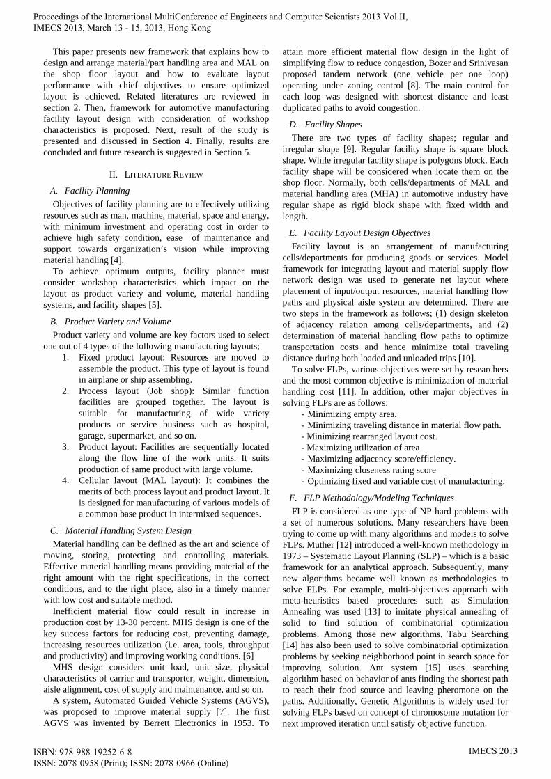
needs to cut the whole production process into a number of assembly lines. After cutting, the lines are connected using additional expensive inter-line work unit transfer equipments. Work units are moved along conveyor system from last workstation of assembly line N to the first workstation of assembly line N+1 via the installed equipments. Furthermore, it also increases unnecessary work-in-process to be the buffer of line-to-line transfer to ensure steadiness of throughputs. For example, there are 58 workstations in the MAL and each workstation’s dimension is 5x13 meters, the dimension of single line MAL is 13x290 meters. However, if the line is cut into three connected lines, the dimension of plant building changes dramatically. Only two inter-line work unit transfer equipments are needed as shown in Figure 3.
- Minimizing cost of empty area: This objective is to ensure that area utilization is maximized in given conditions. It could be achieved when MAL and MHA on the shop floor are effectively placed. - Maximizing adjacency efficiency: This objective is to ensure high work flows of inter-relative cells/departments are adjacently placed. - Minimizing cost of traveling distance: This cost is calculated based on activities relating to supplying parts along material flow path between resources and transporter routing. Efficient design leads to smooth and simplified flow of supply which can improve on-time supply.
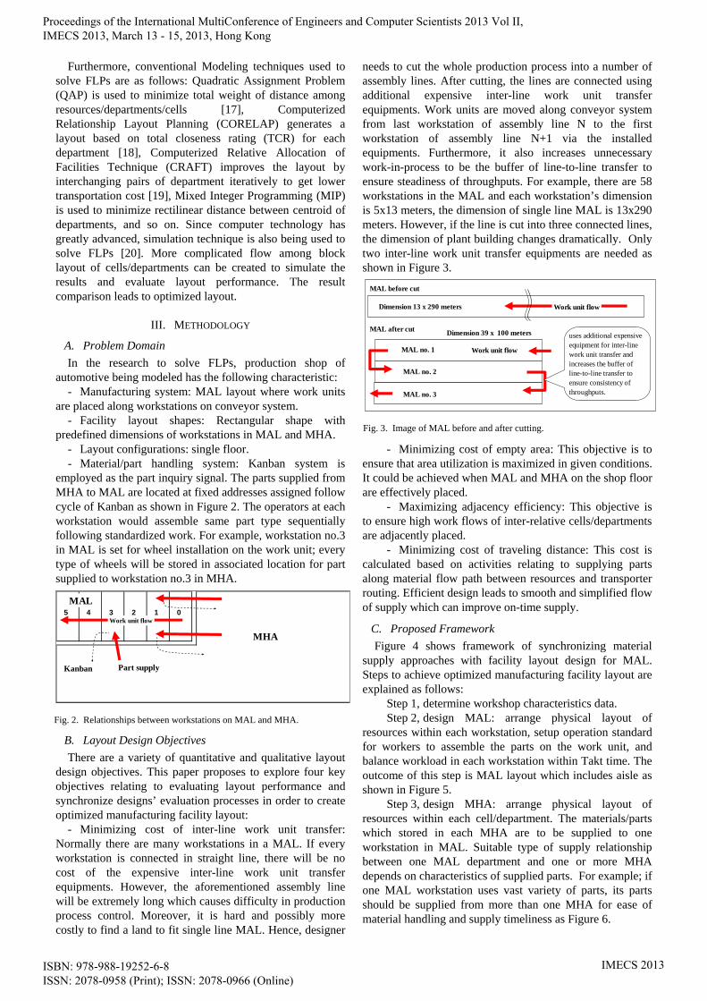
C. Proposed Framework Figure 4 shows framework of synchronizing material
supply approaches with facility layout design for MAL. Steps to achieve optimized manufacturing facility layout are explained as follows: Step 1, determine workshop characteristics data. Step 2, design MAL: arrange physical layout of resources within each workstation, setup operation standard for workers to assemble the parts on the work unit, and balance workload in each workstation within Takt time. The outcome of this step is MAL layout which includes aisle as shown in Figure 5. Step 3, design MHA: arrange physical layout of resources within each cell/department. The materials/parts which stored in each MHA are to be supplied to one workstation in MAL. Suitable type of supply relationship between one MAL department and one or more MHA depends on characteristics of supplied parts. For example; if one MAL workstation uses vast variety of parts, its parts should be supplied from more than one MHA for ease of material handling and supply timeliness as Figure 6.
Fig. 2. Relationships between workstations on MAL and MHA.
345 2 1 0MAL
MHA
Work unit flow
Kanban Part supply
Fig. 3. Image of MAL before and after cutting.
MAL before cut
Work unit flowDimension 13 x 290 meters
Work unit flow
MAL after cut
MAL no. 1
MAL no. 2
MAL no. 3
uses additional expensive equipment for inter-line work unit transfer and increases the buffer of line-to-line transfer to ensure consistency of throughputs.
Dimension 39 x 100 meters
Proceedings of the International MultiConference of Engineers and Computer Scientists 2013 Vol II, IMECS 2013, March 13 - 15, 2013, Hong Kong
ISBN: 978-988-19252-6-8 ISSN: 2078-0958 (Print); ISSN: 2078-0966 (Online)
IMECS 2013
Step 4, cut MAL and MHA: cutting MAL into various
line then cutting MHA with respect to parts to supply to assembly process as shown in table I. In this step, cost of inter-line work unit transfer incurs every time the assembly line is cut in to smaller lines. This cost is one of four proposed objectives for evaluating layout performance.
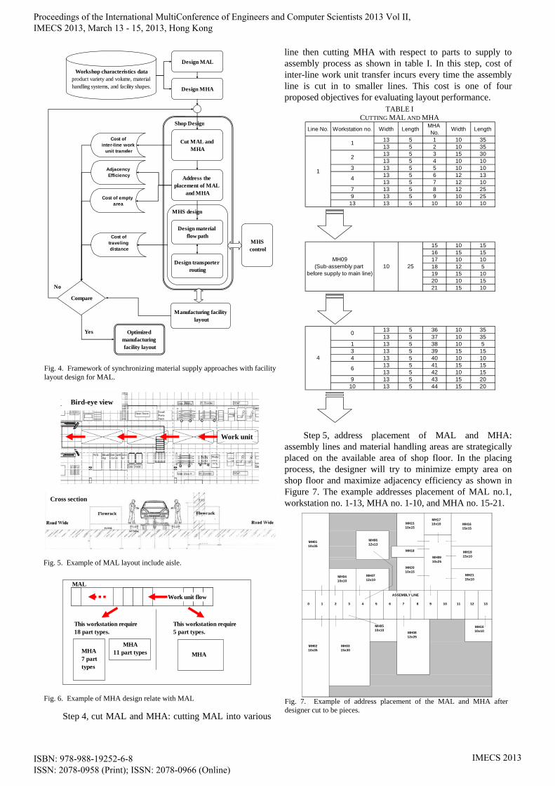
Step 5, address placement of MAL and MHA: assembly lines and material handling areas are strategically placed on the available area of shop floor. In the placing process, the designer will try to minimize empty area on shop floor and maximize adjacency efficiency as shown in Figure 7. The example addresses placement of MAL no.1, workstation no. 1-13, MHA no. 1-10, and MHA no. 15-21.
Fig. 4. Framework of synchronizing material supply approaches with facilitylayout design for MAL.
Workshop characteristics dataproduct variety and volume, material handling systems, and facility shapes.
Design MAL
Compare
Design MHA
Cost of inter-line work
unit transfer
Cost of empty area
Design material flow path
Design transporter routing
Shop Design
MHS design
MHS control
Manufacturing facility layout
Cut MAL and MHA
Yes
No
Optimized manufacturing facility layout
Address the placement of MAL
and MHA
Adjacency Efficiency
Cost of traveling distance
Fig. 5. Example of MAL layout include aisle.
Work unit
Bird-eye view
Cross section
TABLE I CUTTING MAL AND MHA
Line No. Workstation no. Width Length MHA No. Width Length
13 5 1 10 3513 5 2 10 3513 5 3 15 3013 5 4 10 10
3 13 5 5 10 1013 5 6 12 1313 5 7 12 10
7 13 5 8 12 259 13 5 9 10 25
13 13 5 10 10 10
15 10 1516 15 1517 10 1018 12 519 15 1020 10 1521 15 10
13 5 36 10 3513 5 37 10 35
1 13 5 38 10 53 13 5 39 15 154 13 5 40 10 10
13 5 41 15 1513 5 42 10 15
9 13 5 43 15 2010 13 5 44 15 20
1
1
2
4
MH09(Sub-assembly part
before supply to main line)10 25
4
0
6
Fig. 6. Example of MHA design relate with MAL
Work unit flow
This workstation require18 part types.
This workstation require5 part types.
MAL
MHA7 parttypes
MHA11 part types MHA
Fig. 7. Example of address placement of the MAL and MHA afterdesigner cut to be pieces.
0 1 2 3 4 5 6 7 8 9 10 11 12 13
MH0110x35
MH0210x35
MH0410x10
MH0315x30
MH0712x10
MH0510x10
MH0612x13
MH0812x25
MH0910x25
MH1010x10
ASSEMBLY LINE
MH1510x15
MH1615x15
MH1710x10
MH18 MH1915x10
MH2010x15
MH2115x10
Proceedings of the International MultiConference of Engineers and Computer Scientists 2013 Vol II, IMECS 2013, March 13 - 15, 2013, Hong Kong
ISBN: 978-988-19252-6-8 ISSN: 2078-0958 (Print); ISSN: 2078-0966 (Online)
IMECS 2013
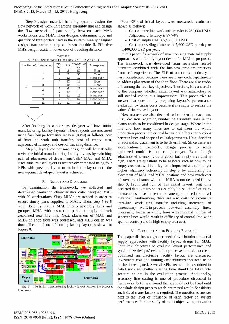
Step 6, design material handling system: design the flow network of work unit among assembly line and design the flow network of part supply between each MAL workstations and MHA. Then designer determines type and quantity of transporters used in the system. Finally designer assigns transporter routing as shown in table II. Effective MHS design results in lower cost of traveling distance.
After finishing these six steps, designer will have initial manufacturing facility layouts. These layouts are measured using four key performance indexes (KPIs) as follows: cost of inter-line work unit transfer, cost of empty area, adjacency efficiency, and cost of traveling distance. Step 7, layout comparison: designer will heuristically revise the initial manufacturing facility layouts by switching pair of placement of departments/cells’ MAL and MHA. Each time, revised layout is recursively compared using four KPIs with previous layout to attain better layout until the near-optimal developed layout is achieved.
IV. RESULT AND DISCUSSION To examination the framework, we collected and
determined workshop characteristics data, designed MAL with 69 workstations. Sixty MHAs are needed in order to ensure timely parts supplied to MALs. Then, step 4 to 6 were done by cutting MAL into 5 assembly lines and grouped MHA with respect to parts to supply to each associated assembly line. Next, placement of MAL and MHA on shop floor was addressed, and MHS design was done. The initial manufacturing facility layout is shown in Figure 8.
Four KPIs of initial layout were measured, results are shown as follows:
- Cost of inter-line work unit transfer is 750,000 USD. - Adjacency efficiency is 87.74%. - Cost of empty area is 5,450,000 USD. - Cost of traveling distance is 5,600 USD per day or
1,400,000 USD per year. In this paper, framework of synchronizing material supply
approaches with facility layout design for MAL is proposed. The framework was developed from reviewing related literature combined with the business problem practices from real experience. The FLP of automotive industry is very complicated because there are many cells/departments to address placement of the shop floor. There are also trade-offs among the four key objectives. Therefore, it is uncertain to the company whether initial layout was satisfactory or still needed continuous improvement. This paper tries to answer that question by proposing layout’s performance evaluation by using costs because it is simple to realize the value of the revised layout.
New matters are also deemed to be taken into account. First, decision regarding number of assembly lines in the plants needs to be considered in design stage. Where in the line and how many lines are to cut from the whole production process are critical because it affects connections between lines and shape of cells/departments. Next, decision of addressing placement is to be determined. Since there are aforementioned trade-offs, design process to reach optimized model is not complete yet. Even though adjacency efficiency is quite good, but empty area cost is high. There are questions to be answers such as how much empty area cost will be if layout is improved with aim to get higher adjacency efficiency in step 5 by addressing the placement of MAL and MHA locations and how much cost of traveling distance will be if MHA is not designed follow step 3. From trial run of this initial layout, wait time occurred due to many short assembly lines – therefore many intersections – as a result of attempts to reduce travel distance. Furthermore, there are also costs of expensive inter-line work unit transfer including increment of unnecessary work-in-process between assembly lines. Contrarily, longer assembly lines with minimal number of separate lines would result in difficulty of control (too wide span of control) and in high empty area cost.
V. CONCLUSION AND FURTHER RESEARCH This paper discloses a greater need of synchronized material supply approaches with facility layout design for MAL. Four key objectives to evaluate layout performance and synchronize designs’ evaluation processes in order to create optimized manufacturing facility layout are discussed. Investment cost and running cost minimization need to be further investigated. Several KPIs needs to be examined in detail such as whether waiting time should be taken into account or not in the evaluation process. Additionally, assembly line cutting is one of procedure discussed in framework, but it was found that it should not be fixed until the whole design process reach optimized result. Sensitivity analysis of many factors is required. The question to answer next is the level of influence of each factor on system performance. Further study of multi-objective optimization
Fig. 8. The initial manufacturing facility layout follows the proposedframework
Empty area
Empty area
Empty area
MAL
MHA
TABLE II MHS DESIGN LOT SIZE, FREQUENCY, AND TRANSPORTER
Line No. Workstation no. MHA No. Lot Frequency/
shift Transporter
1 3 50 E-car2 3 50 E-car3 12 13 Hand push4 12 13 E-car
3 5 12 13 E-car6 6 25 Hand push7 12 13 Hand push
7 8 12 13 Hand push9 9 1 148 Hand push13 10 12 13 E-car
1
1
2
4
Proceedings of the International MultiConference of Engineers and Computer Scientists 2013 Vol II, IMECS 2013, March 13 - 15, 2013, Hong Kong
ISBN: 978-988-19252-6-8 ISSN: 2078-0958 (Print); ISSN: 2078-0966 (Online)
IMECS 2013
methodology to optimize more than three objective functions is also required if all four objectives are equally important.
REFERENCES [1] G. Aiello, M. Enea, and G. Galante, “An integrated approach to the
facilities and material handling system design,” International Journal of Production Research, vol. 40, no. 15, pp. 4007–4017, 2002.
[2] S. P. Singh and R. R. K. Sharma, “A review of different approaches to the facility layout problems,” International Journal of Advanced Manufacturing Technology, vol. 30, pp. 425-433, 2006.
[3] A. S. Ramkumar, S. G. Ponnambalam, and N. Jawahar, “A new iterated fast local search heuristic for solving QAP formulation in facility layout design, ” Robotics and Computer-Integrated Manufacturing, vol. 25, pp. 620-629, 2009.
[4] J. A. White, “SFP-Strategic Facilities Planning,” Modern Materials Handling, pp. 23–25, 1978.
[5] A. Drira, H. Pierreval, and S. Hajri-Gabouj, “Facility layout problems: A survey,” Annual Reviews in Control, vol. 31, pp. 255–267, 2007.
[6] G. Aiello, M. Enea, and G. Galante, “An integrated approach to the facilities and material handling system design,” International Journal of Production Research, vol. 40, no. 15, pp. 4007–4017, 2002.
[7] L. Qiu, W. J. Hsu, S. Y. Huang, and H. Wang, “Scheduling and routing algorithms for AGVs: A survey,” International Journal of Production Research, vol. 40, no. 3, pp. 745–760, 2002.
[8] Y. A. Bozer, and M. M. Srinivasan, “Tandem configurations for automated guided vehicle systems and the analysis of single vehicle loops,” IIE Transactions, vol. 23, no. 1, pp. 23–27, 1991.
[9] G. C. Lee, and Y. D. Kim, “Algorithms for adjusting shapes of departments in block layouts on the grid-based plane,” Omega, vol. 28, no. 1, pp. 111-122, 2000.
[10] G. Ioannou, and I. Minis, “An integrated approach to the design of manufacturing facilities,” Institute for Systems Research, University of Maryland, College Park, MD., 1995.
[11] A. Kundu, and P. K. Dan, “The scope of genetic algorithms in dealing with facility layout problems,” South African Journal of Industrial Engineering, vol. 21, no. 2, pp. 39-49, 2010.
[12] R. Muther, Systematic layout planning, CBI Publishing Company Inc., 1973.
[13] R. Sahin, “A simulated annealing algorithm for solving the bi-objective facility layout problem,” Expert Systems with Applications, Elsevier, vol. 38, pp. 4460-4465, 2011.
[14] A. R. Mckendell, and A. Hakobyan, “Heuristic for the dynamic facility layout problem with unequal, area departments,” European Journal of Operations Research, vol. 201, pp. 171-182, 2010.
[15] Komarudin, and K. Y. Wong, “Solving facility layout problems using flexible bay structure representation and ant system algorithm,” Expert System with Applications, vol. 37, pp. 5523-5527, 2010.
[16] M. J. A. Diego, S. M. C. Santamarina, M. J. Alcaide, and B. V. A. Cloquell, “Solving facility layout problems with strict geometric constraints using a two phase genetic algorithm,” International Journal of Production Research, vol. 6, no. 15, pp. 1679-1693, 2009.
[17] A. S. Ramkumar, S. G. Ponnambalam, and N. Jawahar, “A new iterated fast local search heuristic for solving QAP formulation in facility layout design,” Robotics and Computer-Integrated Manufacturing, vol. 25, pp. 620-629, 2009.
[18] R. Lee, and J. M. Moore, “CORELAP – Computerized relationship layout planning,” Journal of Industrial Engineering, vol. 18, no. 3, pp. 195–200, 1967.
[19] G. C. Armour, and E. S. Buffa, “A heuristic algorithm and simulation approach to the relative location of facilities,” Management Science, vol. 9, no. 1, pp. 294–309, 1963.
[20] J. Zhenyuan, L. Xiaohong, W. Wei, J. Defeng, and W. Lijun, “Design and implementation of lean facility layout system of a production line,” International Journal of Industrial Engineering, vol. 18, no. 5, pp. 260-269, 2011.
Proceedings of the International MultiConference of Engineers and Computer Scientists 2013 Vol II, IMECS 2013, March 13 - 15, 2013, Hong Kong
ISBN: 978-988-19252-6-8 ISSN: 2078-0958 (Print); ISSN: 2078-0966 (Online)
IMECS 2013