Embed Size (px)
Citation preview
THE GIANT-VAC
‘WHISPER JET’ BLOWER MODELS 60-BWJ – 85-KWJ – 85-KWJT – 90-HWJ –
10-BWJ - 11-BWJ – 12-KWJ - 16-BWJ
OPERATOR’S MANUAL Congratulations! You have just purchased one of the finest pieces of outdoor power equipment on the market today. If properly cared for, your Giant-Vac Whisper Jet Blower will provide years of dependable service. Please read and follow this instruction manual carefully in order to get the most out of your new equipment. As you unpack your Whisper Jet, you will find the following parts: 1 - Whisper Jet power unit 1 - Handle assembly in three parts 1 - Bag containing front wheel assembly 1 - Package of hardware 1 - Package containing operating manuals and warranty registration Your Giant-Vac Whisper Jet Blower requires very little assembly. Simply follow the instructions contained within this manual to begin enjoying the benefits of your new unit. Each Giant-Vac product leaves our factory in excellent condition; occasionally, however, some damage may occur during shipment. If any such damage is found upon initial inspection, immediately notify the transport carrier who delivered your machine, as they are solely responsible for such damage, as well as any subsequent adjustments necessary.
CALIFORNIA PROPOSITION 65 WARNING
Gasoline and Diesel engine exhaust and some of its constituents are known to the
State of California to cause cancer, birth defects and other reproductive harm.
As an owner of off-road gasoline or diesel engine equipment and/or as an employer, you also may have an obligation under the California Occupational Safety and Health Act or under Proposition 65 to warn persons exposed to gas and diesel
engine exhaust and/or other Proposition 65 chemicals in and around your workplace. See California Health and Safety Code section 25249.5, Title 22 of the
California Code of Regulations at Section 1200 er seq., and Title 8 of the California Code of Regulations Section 5194.
7/01 Revision
SAFETY RULES REGARDING OUTDOOR POWER EQUIPMENT
IMPORTANT! READ THE FOLLOWING SAFETY RULES CAREFULLY BEFORE ASSEMBLING OR OPERATING UNIT: • Regard your Giant-Vac Leaf Blower as a piece of power equipment and teach
this regard to all who will operate this unit. Never allow children or young teenagers to operate the unit.
• Always wear appropriate safety equipment when operating this unit. Proper
eye, ear, and breathing protection is a must. • Be sure you know how to stop both the unit and the engine at a MOMENT’S
NOTICE. Refer to the operation section of this manual, as well as the engine manual.
• Do not operate with any guards or component parts removed from unit. • Unless there is very good artificial light, use only during daylight. • Fill gasoline driven machines outdoors. Avoid spilling gasoline and DO NOT
fill the engine while it is running or while you are smoking. • While in operation, keep all parts of body away from intake and exhaust
sections. Never insert any body part or other foreign object in any opening while the machine is running.
• When operating unit, keep people and pets a safe distance away. Instruct
children to keep away from the area of operation at all times. • Do not use on steep inclines (over 30 degrees), as unit can roll over. • Before making any adjustments or repairs, stop engine and remove spark plug
wire. FAILURE TO FOLLOW THESE RULES CAN RESULT IN CHRONIC HEALTH PROBLEMS, SERIOUS INJURY, OR EVEN DEATH.
1
UNIT ASSEMBLY
1. HANDLE ASSEMBLY: Please refer to Parts list for correct part identification and placement
• Insert Lower handles (Parts List Ref. #14) into Upper handle (#13) until bolt holes are
aligned (use middle set of holes in lower handle, then adjust later for most comfortable height). Fasten with two 5/16 x 1-3/4” hex bolts (#15), lockwashers (#4) and nuts (#16). 16 HP units only: Align holes in rear (forked) end of handle brace (#10) with upper set of holes in upper handle and fasten with same hardware as above. Attach handle brace extension (#10a) to front of brace with 3/8 x 1” bolt, lockwasher & nut (#10b,11,12). Do not tighten these bolts yet.
• Attach lower portion of handle assembly to engine base with four 5/16 x 1-3/4” bolts,
lockwashers, and nuts. 16 HP units only: Slide hole in front end of handle brace extension onto stud in top of blower housing and fasten with 3/8 lockwasher (#11) and nut (#12). Tighten all handle assembly bolts securely.
• Attach Throttle control (#17) to corresponding holes in upper left corner of handle assembly
with two #10 x 1-1/4” machine screws, lockwashers and nuts (#18). Note: Be sure to attach throttle control to outside of handle assembly. Secure throttle cable to handle with two throttle cable clips (#18a), placing one just below where handle brace joins with upper handle, the other 4-5” above bend in lower handle. Note: Be sure to check throttle for smooth operation. If throttle lever binds, or is difficult to operate, adjust cable and clips accordingly.
2. FRONT WHEEL ASSEMBLY: • Attach front wheel assembly to unit by placing Front wheel bracket (#31) against front lower
corner of unit (next to blower discharge door), making sure mounting holes in both parts are aligned. Fasten with three 3/8 x 3/4” hex bolts (#35) and lockwashers (#35a). Leave all bolts finger tight.
• Install Front wheel (#34)* inside bracket with 5/8 x 5” hex bolt (#32), and fasten with 5/8” hex
lock jam nut (#33), tightening just enough to allow wheel to spin freely, but with a minimum amount of play within bracket. * It is advisable to grease front wheel before installation. This will result in longer bearing life.
• Check caster wheel for proper camber, adjust as necessary, then tighten bolts securing
assembly to unit. Assembly of your Giant-Vac Whisper Jet Blower is now complete. Please read carefully the following instructions for safe and effective use of your Whisper Jet.
2
UNIT OPERATION
1. STARTING THE ENGINE IMPORTANT NOTE: The procedures outlined within this section are general guidelines, and are in no way meant to replace or supercede engine manufacturer’s operating instructions. In order to obtain optimum performance from your engine, refer to your engine manual. BEFORE STARTING ENGINE: • Be sure that the unit is completely assembled, all fasteners are tightened securely, and all
safety guards and components are in place. • Be sure to check engine’s oil and gasoline*. (See engine manual for recommended oil and
gasoline specifications.) Never check the engine while it is running or while you are smoking. Check only when engine is cold.
* All machines are shipped without oil or gasoline unless otherwise noted. • Be sure that fuel valve on engine is set to open position (if applicable). TO START ENGINE : • Set throttle control to “ON” position. If engine is cold, set choke (if so equipped). If your
engine has a fuel prime button, depress it firmly three times. • Grasp recoil handle and pull briskly. You may have to pull several times before engine
starts. (If engine fails to start within a reasonable amount of time, discontinue and check engine manual for further instructions.)
• After engine starts, move throttle control down to approximately half, and turn off choke. TO SHUT ENGINE DOWN : • Allow engine to idle for 2-3 minutes before shutting down. • Set throttle control to ‘off’ position. • If engine is not to be started for a prolonged period, turn fuel valve to closed position. IMPORTANT NOTE: If you experience problems with your engine that cannot be satisfactorily resolved by following the instructions contained within the engine manual, contact your local engine dealer, or call the toll-free service number listed in the repair section of the engine manual. All engine service, warranty or otherwise, is required to be performed by a manufacturer-authorized service center. Giant-Vac Mfg., Inc. is neither authorized nor responsible for any type of warranty engine service, nor is it equipped to perform any such service.
3
UNIT OPERATION (Cont.)
2. OPERATING THE BLOWER: DANGER! Do not pass by or stand on the air discharge side of any leaf blower with the engine running. High velocity discharge can easily turn harmless debris into flying projectiles. TO BLOW DEBRIS OUT TOWARD FRONT OF UNIT: • Open the forward air deflector door, mounted on the front of the discharge end of the
blower, by pushing the control lever to the front of the machine. This feature is ideal for such things as blowing debris from a wall or fence. Adjust engine speed to increase or decrease air discharge rate. NEVER INSERT ANY BODY PART OR OTHER FOREIGN OBJECT IN THE OPENING WHILE THE MACHINE IS RUNNING.
TO BLOW DEBRIS OUT TOWARD SIDE OF UNIT: • Close the front air deflector door by pulling the control lever back toward the rear of the
machine, and adjust the side air deflector, mounted on the discharge end of the blower, by means of the 5/16 x 5/8” hex bolts on either end of the deflector. This will permit you to direct the air at the angle you desire for a specific application. Adjust engine speed to increase or decrease air discharge rate. By changing the deflector angle and the engine speed, you can move debris into a neat row easily and rapidly. NEVER INSERT ANY BODY PART OR OTHER FOREIGN OBJECT IN THIS OPENING WHILE THE MACHINE IS RUNNING.
HINTS FOR EFFECTIVE OPERATION: • For operator ease and maneuverability, push down on the upper handle while walking so
that the machine balances on the rear wheels. • When blowing dry debris, set blower discharge to lower rate; when blowing wet or frozen
debris, increase discharge rate.
3
MAINTENANCE AND STORAGE • Follow implicitly the engine manufacturer’s recommendations for maintenance. • Never make any adjustments to the Whisper Jet until the engine is off and the spark plug
wire is disconnected. • If carburetor adjustment is necessary, stand to one side and keep feet and hands in the
clear while making adjustments. • Keep engine free of accumulations of grass, leaves or excessive grease. An accumulation
of these combustible materials may result in a fire. • Store gasoline in a safe and approved container in a cool, dry place. • Keep the Whisper Jet and any fuel containers in locked storage to prevent children from
playing and/or tampering with them. • Do not store gasoline powered equipment or fuel containers in a basement or any closed
area where heating or heat appliances or open pilot lights are present, unless the fuel is completely drained from the power equipment and the fuel containers.
4
GIANT-VAC WARRANTY
GIANT-VAC, INC., here-in-after called Giant-Vac, warrants each new Giant-Vac to the original retail purchaser of the new Giant-Vac equipment to be free from manufacturing defects in normal service for a period of 1 year, unless it is used for rental purposes, which limits the warranty to 30 days. This warranty does not apply to engines, tires or other parts that are purchased and warranted by their manufacturer. Items such as bags, grass catchers, hoses and blades are not warranted, as these are considered expendable items. This warranty does not include equipment failures due to normal wear. Any obligation under this warranty is expressly limited to the replacement or repair, at an authorized servicing Giant-Vac dealer, or at a point designated by us, of such parts as appear to us to have been defective. All defective parts have to be returned freight prepaid before credit will be issued. We shall not be liable for transportation charges in connection with the replacement or repair of defective parts. This warranty does not apply to a Giant-Vac upon which repairs or alterations have been made by others except with our prior written approval. We shall not be liable for consequential damages or contingent liabilities for the fitness of any Giant-Vac for any particular purpose. We make no other express, implied or statutory warranty, nor is anyone authorized to make any in our behalf.
GIANT-VAC, INC. P.O. BOX 195
SOUTH WINDHAM, CT. 06266 PHONE: 860-423-7741 • FAX: 860-423-2654
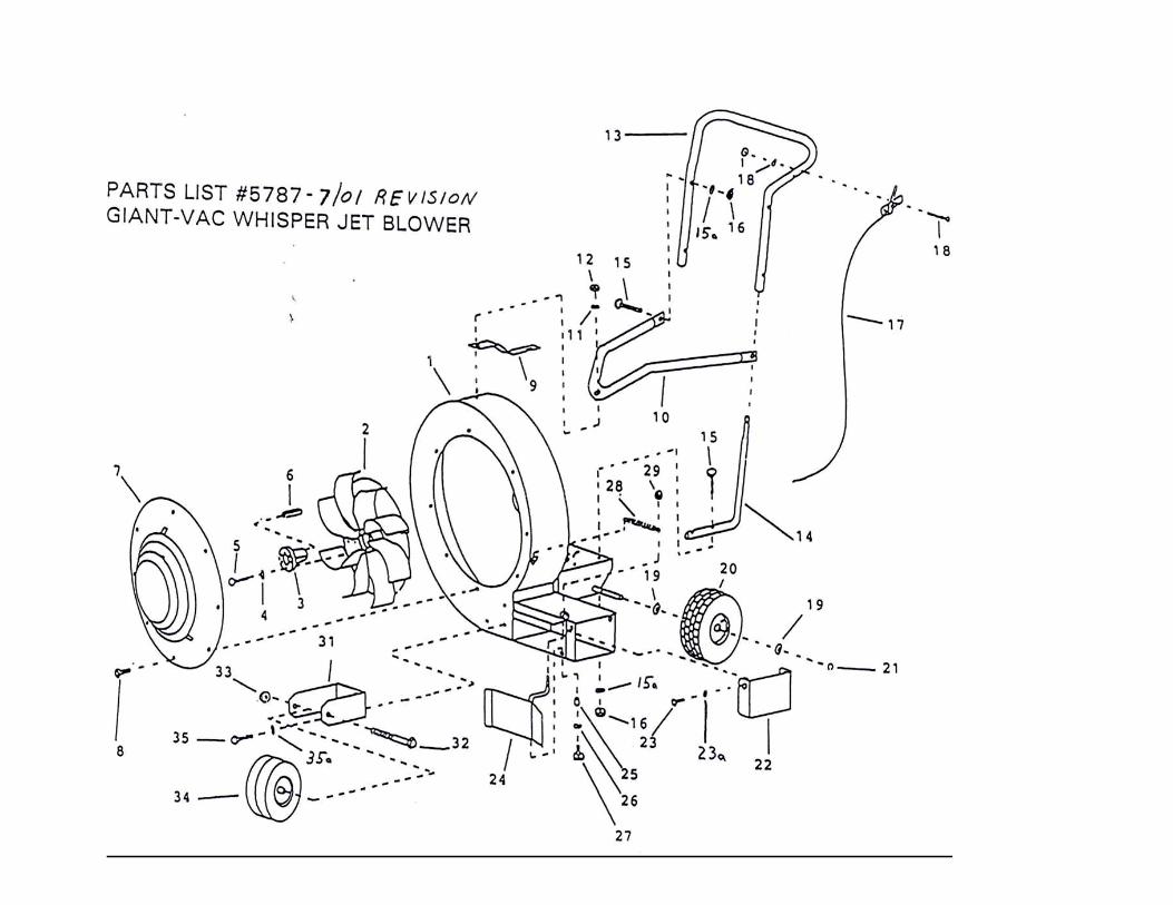
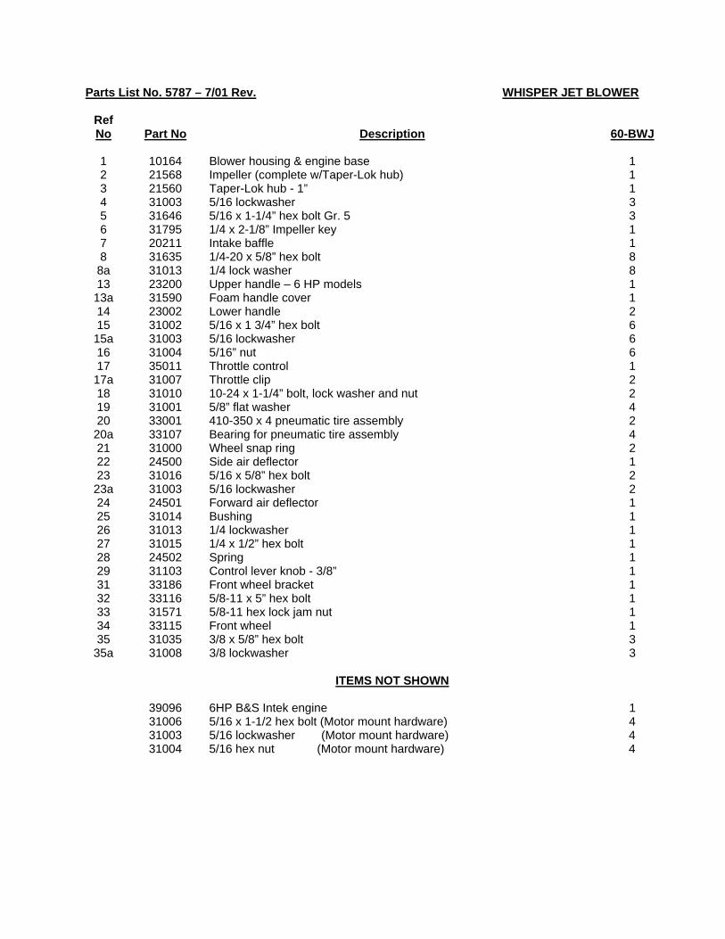
Parts List No. 5787 – 7/01 Rev. WHISPER JET BLOWER
Ref No
Part No
Description
60-BWJ
1 10164 Blower housing & engine base 1 2 21568 Impeller (complete w/Taper-Lok hub) 1 3 21560 Taper-Lok hub - 1” 1 4 31003 5/16 lockwasher 3 5 31646 5/16 x 1-1/4” hex bolt Gr. 5 3 6 31795 1/4 x 2-1/8” Impeller key 1 7 20211 Intake baffle 1 8 31635 1/4-20 x 5/8” hex bolt 8 8a 31013 1/4 lock washer 8 13 23200 Upper handle – 6 HP models 1
13a 31590 Foam handle cover 1 14 23002 Lower handle 2 15 31002 5/16 x 1 3/4” hex bolt 6
15a 31003 5/16 lockwasher 6 16 31004 5/16” nut 6 17 35011 Throttle control 1
17a 31007 Throttle clip 2 18 31010 10-24 x 1-1/4” bolt, lock washer and nut 2 19 31001 5/8” flat washer 4 20 33001 410-350 x 4 pneumatic tire assembly 2
20a 33107 Bearing for pneumatic tire assembly 4 21 31000 Wheel snap ring 2 22 24500 Side air deflector 1 23 31016 5/16 x 5/8” hex bolt 2
23a 31003 5/16 lockwasher 2 24 24501 Forward air deflector 1 25 31014 Bushing 1 26 31013 1/4 lockwasher 1 27 31015 1/4 x 1/2” hex bolt 1 28 24502 Spring 1 29 31103 Control lever knob - 3/8” 1 31 33186 Front wheel bracket 1 32 33116 5/8-11 x 5” hex bolt 1 33 31571 5/8-11 hex lock jam nut 1 34 33115 Front wheel 1 35 31035 3/8 x 5/8” hex bolt 3
35a 31008 3/8 lockwasher 3 ITEMS NOT SHOWN 39096 6HP B&S Intek engine 1 31006 5/16 x 1-1/2 hex bolt (Motor mount hardware) 4 31003 5/16 lockwasher (Motor mount hardware) 4 31004 5/16 hex nut (Motor mount hardware) 4
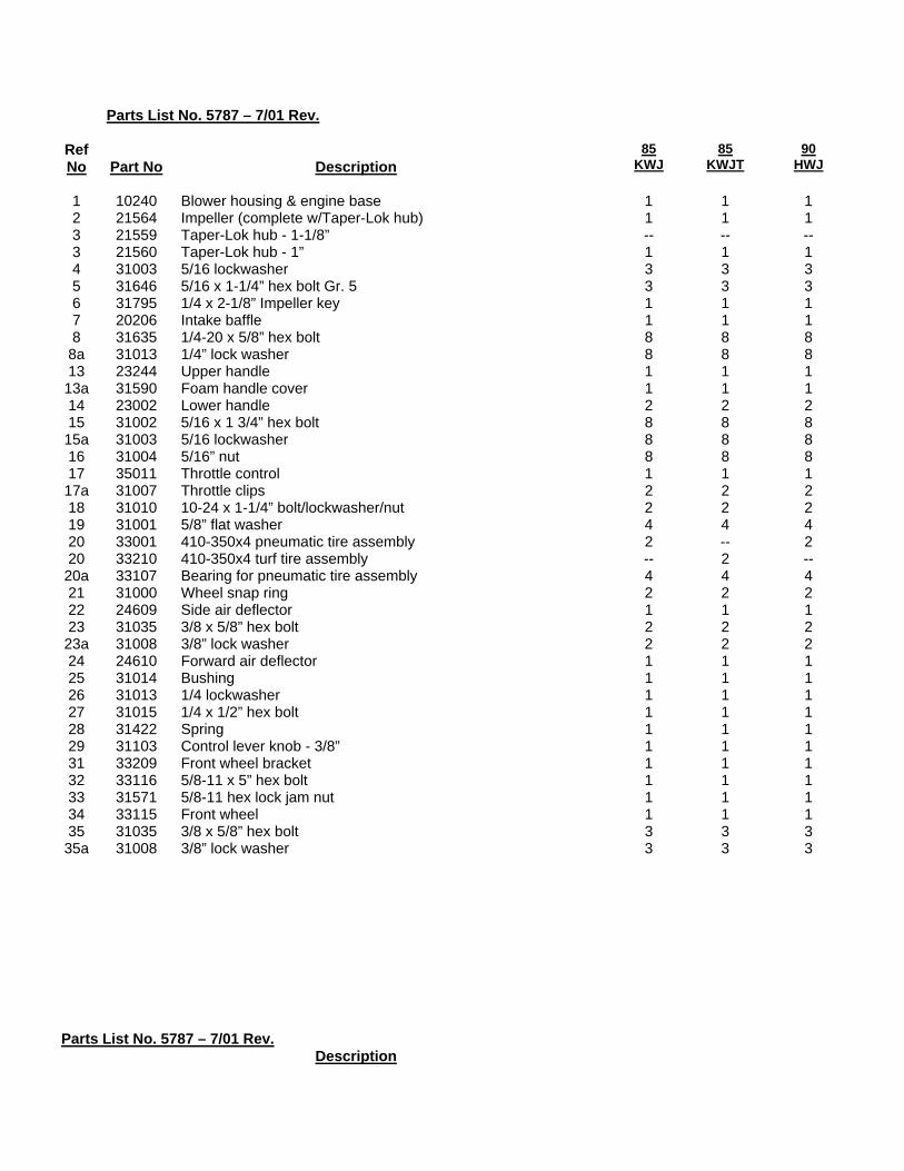
Parts List No. 5787 – 7/01 Rev.
Ref No
Part No
Description
85 KWJ
85 KWJT
90 HWJ
1 10240 Blower housing & engine base 1 1 1 2 21564 Impeller (complete w/Taper-Lok hub) 1 1 1 3 21559 Taper-Lok hub - 1-1/8” -- -- -- 3 21560 Taper-Lok hub - 1” 1 1 1 4 31003 5/16 lockwasher 3 3 3 5 31646 5/16 x 1-1/4” hex bolt Gr. 5 3 3 3 6 31795 1/4 x 2-1/8” Impeller key 1 1 1 7 20206 Intake baffle 1 1 1 8 31635 1/4-20 x 5/8” hex bolt 8 8 8
8a 31013 1/4” lock washer 8 8 8 13 23244 Upper handle 1 1 1 13a 31590 Foam handle cover 1 1 1 14 23002 Lower handle 2 2 2 15 31002 5/16 x 1 3/4” hex bolt 8 8 8 15a 31003 5/16 lockwasher 8 8 8 16 31004 5/16” nut 8 8 8 17 35011 Throttle control 1 1 1 17a 31007 Throttle clips 2 2 2 18 31010 10-24 x 1-1/4” bolt/lockwasher/nut 2 2 2 19 31001 5/8” flat washer 4 4 4 20 33001 410-350x4 pneumatic tire assembly 2 -- 2 20 33210 410-350x4 turf tire assembly -- 2 -- 20a 33107 Bearing for pneumatic tire assembly 4 4 4 21 31000 Wheel snap ring 2 2 2 22 24609 Side air deflector 1 1 1 23 31035 3/8 x 5/8” hex bolt 2 2 2 23a 31008 3/8” lock washer 2 2 2 24 24610 Forward air deflector 1 1 1 25 31014 Bushing 1 1 1 26 31013 1/4 lockwasher 1 1 1 27 31015 1/4 x 1/2” hex bolt 1 1 1 28 31422 Spring 1 1 1 29 31103 Control lever knob - 3/8” 1 1 1 31 33209 Front wheel bracket 1 1 1 32 33116 5/8-11 x 5” hex bolt 1 1 1 33 31571 5/8-11 hex lock jam nut 1 1 1 34 33115 Front wheel 1 1 1 35 31035 3/8 x 5/8” hex bolt 3 3 3 35a 31008 3/8” lock washer 3 3 3
Parts List No. 5787 – 7/01 Rev. Description
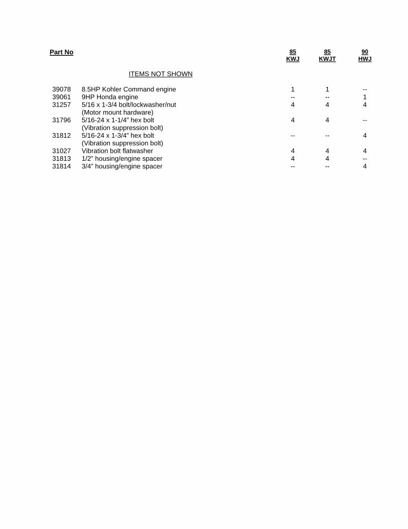
Part No 85 KWJ
85 KWJT
90 HWJ
ITEMS NOT SHOWN 39078 8.5HP Kohler Command engine 1 1 -- 39061 9HP Honda engine -- -- 1 31257 5/16 x 1-3/4 bolt/lockwasher/nut
(Motor mount hardware) 4 4 4
31796 5/16-24 x 1-1/4” hex bolt (Vibration suppression bolt)
4 4 --
31812 5/16-24 x 1-3/4” hex bolt (Vibration suppression bolt)
-- -- 4
31027 Vibration bolt flatwasher 4 4 4 31813 1/2” housing/engine spacer 4 4 -- 31814 3/4” housing/engine spacer -- -- 4
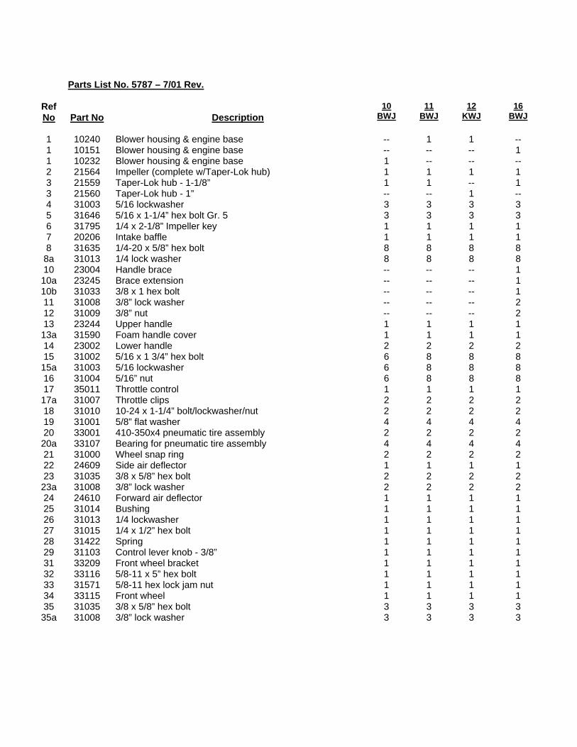
Parts List No. 5787 – 7/01 Rev.
Ref No
Part No
Description
10 BWJ
11 BWJ
12 KWJ
16 BWJ
1 10240 Blower housing & engine base -- 1 1 -- 1 10151 Blower housing & engine base -- -- -- 1 1 10232 Blower housing & engine base 1 -- -- -- 2 21564 Impeller (complete w/Taper-Lok hub) 1 1 1 1 3 21559 Taper-Lok hub - 1-1/8” 1 1 -- 1 3 21560 Taper-Lok hub - 1” -- -- 1 -- 4 31003 5/16 lockwasher 3 3 3 3 5 31646 5/16 x 1-1/4” hex bolt Gr. 5 3 3 3 3 6 31795 1/4 x 2-1/8” Impeller key 1 1 1 1 7 20206 Intake baffle 1 1 1 1 8 31635 1/4-20 x 5/8” hex bolt 8 8 8 8
8a 31013 1/4 lock washer 8 8 8 8 10 23004 Handle brace -- -- -- 1 10a 23245 Brace extension -- -- -- 1 10b 31033 3/8 x 1 hex bolt -- -- -- 1 11 31008 3/8” lock washer -- -- -- 2 12 31009 3/8” nut -- -- -- 2 13 23244 Upper handle 1 1 1 1 13a 31590 Foam handle cover 1 1 1 1 14 23002 Lower handle 2 2 2 2 15 31002 5/16 x 1 3/4” hex bolt 6 8 8 8 15a 31003 5/16 lockwasher 6 8 8 8 16 31004 5/16” nut 6 8 8 8 17 35011 Throttle control 1 1 1 1 17a 31007 Throttle clips 2 2 2 2 18 31010 10-24 x 1-1/4” bolt/lockwasher/nut 2 2 2 2 19 31001 5/8” flat washer 4 4 4 4 20 33001 410-350x4 pneumatic tire assembly 2 2 2 2 20a 33107 Bearing for pneumatic tire assembly 4 4 4 4 21 31000 Wheel snap ring 2 2 2 2 22 24609 Side air deflector 1 1 1 1 23 31035 3/8 x 5/8” hex bolt 2 2 2 2 23a 31008 3/8” lock washer 2 2 2 2 24 24610 Forward air deflector 1 1 1 1 25 31014 Bushing 1 1 1 1 26 31013 1/4 lockwasher 1 1 1 1 27 31015 1/4 x 1/2” hex bolt 1 1 1 1 28 31422 Spring 1 1 1 1 29 31103 Control lever knob - 3/8” 1 1 1 1 31 33209 Front wheel bracket 1 1 1 1 32 33116 5/8-11 x 5” hex bolt 1 1 1 1 33 31571 5/8-11 hex lock jam nut 1 1 1 1 34 33115 Front wheel 1 1 1 1 35 31035 3/8 x 5/8” hex bolt 3 3 3 3 35a 31008 3/8” lock washer 3 3 3 3
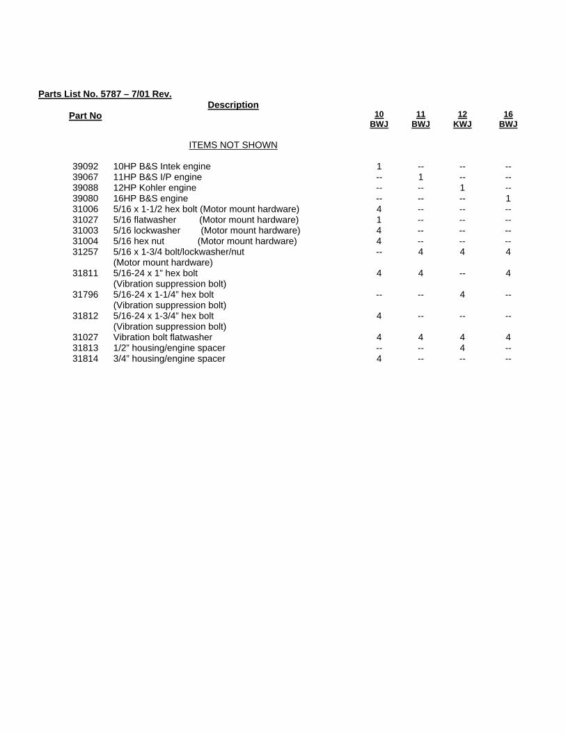
Parts List No. 5787 – 7/01 Rev.
Part No Description
10 BWJ
11
BWJ
12
KWJ
16
BWJ ITEMS NOT SHOWN 39092 10HP B&S Intek engine 1 -- -- -- 39067 11HP B&S I/P engine -- 1 -- -- 39088 12HP Kohler engine -- -- 1 -- 39080 16HP B&S engine -- -- -- 1 31006 5/16 x 1-1/2 hex bolt (Motor mount hardware) 4 -- -- -- 31027 5/16 flatwasher (Motor mount hardware) 1 -- -- -- 31003 5/16 lockwasher (Motor mount hardware) 4 -- -- -- 31004 5/16 hex nut (Motor mount hardware) 4 -- -- -- 31257 5/16 x 1-3/4 bolt/lockwasher/nut
(Motor mount hardware) -- 4 4 4
31811 5/16-24 x 1” hex bolt
(Vibration suppression bolt) 4 4 -- 4
31796 5/16-24 x 1-1/4” hex bolt (Vibration suppression bolt)
-- -- 4 --
31812 5/16-24 x 1-3/4” hex bolt (Vibration suppression bolt)
4 -- -- --
31027 Vibration bolt flatwasher 4 4 4 4 31813 1/2” housing/engine spacer -- -- 4 -- 31814 3/4” housing/engine spacer 4 -- -- --