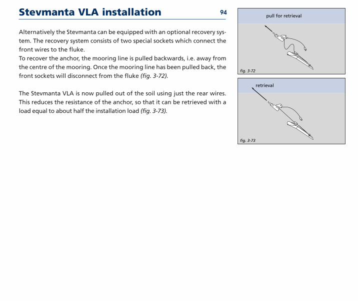
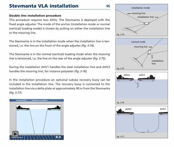
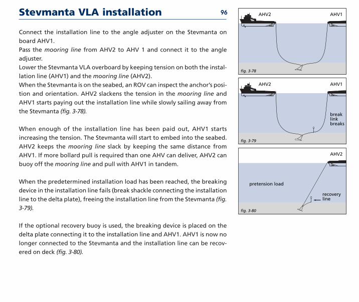
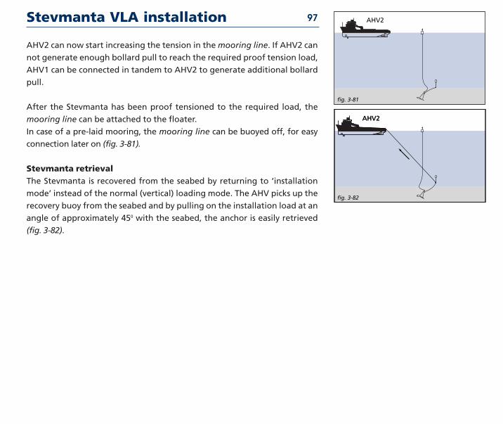
Embed Size (px)
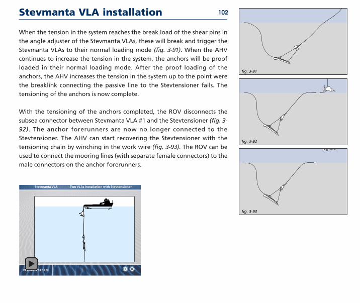
Citation preview
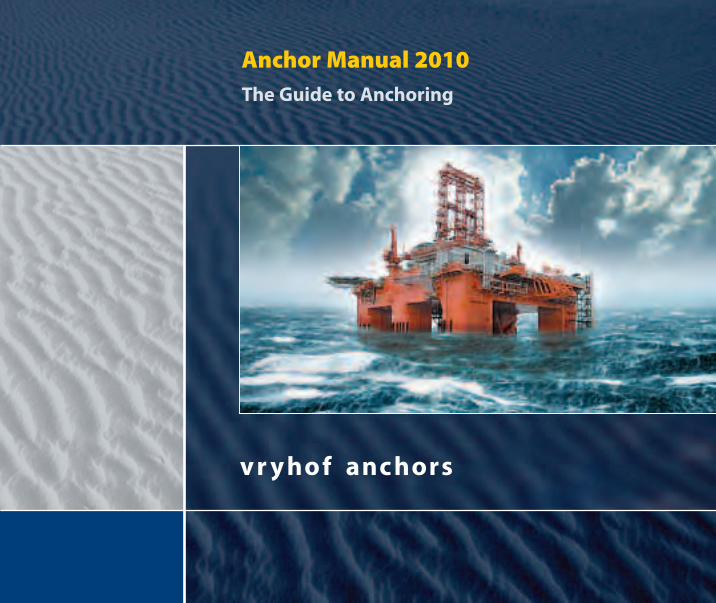
Anchor Manual 2010The Guide to Anchoring
anchor manual 2010
Copyrightcopy Vryhof Anchors BV Capelle ad Yssel The Netherlands 2010No part of this book may be reproduced in any form by print copy or in any other way withoutwritten permission of vryhof
Vryhof Stevin Stevpris Stevshark Stevtensioner and Stevmanta are registered trade marks
Vryhof reserves all intellectual and industrial property rights such as any and all of their patenttrademark design manufacturing reproduction use and sales rights thereto and to any article disclosed therein
All information in this manual is subject to change without prior notice Vryhof Anchors is notliable andor responsible in any way for the information provided in this manual
First edition published 1984 Print run 7500 copiesSecond edition published 1990 Print run 7500 copiesReprint second edition Print run 5000 copiesThird edition published 2000 Print run 2500 copiesReprint third edition print run 1500 copiesSecond reprint third edition print run 1000 copiesFirst print fourth edition published 2006 print run 1000 copiesSecond print fourth edition print run 1000 copiesThird print fourth edition print run 1000 copiesFourth print fourth edition print run 1000 copies
2
Vryh of Anchors BV
PO Box 109 2900 AC Capelle ad Yssel The Neth er lands
wwwvryhofcom vryhofvryhofcom
Since the beginning of exploration of oil amp gas offshore the art of anchoring
has taken a dramatic turn Vryhof Anchors was one of the pioneers and
achieved holding powers up to 25 times an anchors own weight
Consequently the company soon emerged as market leader in anchor
design and manufacturing and with over 7500 units sold its anchors are
the most applied offshore
Vryhof understood that clientsrsquo needs cannot be satisfied by supply of
standard hardware alone With best-in-class sales services it shared technology
to create fit-for-purpose mooring systems it initiated leasepurchase
concepts and introduced an alliance of leading mooring component manu-
facturers in order to more efficiently serve a changing offshore industry in
the 1990s
Exploration in ever deeper waters and more remote locations has encour-
aged the development of more advanced mooring solutions Consequently
Vryhof anchor holding powers now reach beyond 75x their weight Once
again the industry welcomes new ways of cooperation to include supply of
complete mooring systems and lease concepts
This sets the stage for Vryhof who under new private ownership and with
a presence in major offshore arenarsquos will continue to responsibly introduce
quality designs in pace with industrys requirements to explore opportunities
to approach clients in an open sincere professional manner and take its
world class services well into a new era for the benefit and satisfaction of its
clients
Company profile
Introduction
A stone and something that looked like a rope For millennia this was the
typical anchor Over the last 25 years of more recent history vryhof has
brought the art to a more mature status They have grown into a world
leader in engineering and manufacturing of mooring systems for all kinds
of floating structures In doing so the company has secured numerous
anchor and ancillary equipment patents and shared its experience with others
The company understands that the needs of the industry can not be satisfied
by the supply of standard hard-ware only Universal and tailored solutions
rooted in proven engineering should be based on long practical experience
Vryhof has been and will be introducing new and original anchor designs
well into the 21st century With their products advice and this manual it
shares this knowledge with those who are daily faced with complex mooring
situations
This manual is intended as a means of reference for all who purchase use
maintain repair or are in any way involved with anchors Though written
from one anchor manufacturerrsquos standpoint the information contained
herein is applicable to many types of anchors Total objectivity is of course
impossible
It is hoped this manual will contribute to the work and success of all who
work with anchors They are the only fixed reference point for many of the
floating structures on the worldrsquos often turbulent waters
4
General
1
Mooring systems
Mooring systems have been around just as long as man has felt the need for
anchoring a vessel at sea These systems were used and are still used on
ships and consisted of one or more lines connected to the bow or stern of
the ship Generally the ships stayed moored for a short duration of time
(days)
When the exploration and production of oil and gas started offshore a
need for more permanent mooring systems became apparent Numerous
different mooring systems have been developed over the years of which a
short selection is presented here
Semi-submersible drilling rig - generally the semi-submersibles are
moored using an eight point mooring Two mooring lines come together at
each of the columns of the semi-submersible
CALM buoy - generally the buoy will be moored using four or more moor-
ing lines at equally spaced angles The mooring lines generally have a cate-
nary shape The vessel connects to the buoy with a single line and is free to
weathervane around the buoy
SALM buoy - these types of buoys have a mooring that consists of a single
mooring line attached to an anchor point on the seabed underneath the
buoy The anchor point may be gravity based or piled
Turret mooring - this type of mooring is generally used on FPSOs and FSOs
in more harsh environments Multiple mooring lines are used which come
together at the turntable built into the FPSO or FSO The FPSO or FSO is able
to rotate around the turret to obtain an optimal orientation relative to the
prevailing weather conditions
13semi-sub mooring
13
typical turret mooring
6
fig 1-01
catenary system
fig 1-02
taut leg system
Spread mooring - generally used on FPSOs and FSOs in milder environ-
ments The mooring lines are directly connected to the FPSO or FSO at both
the stern and bow of the vessel
When oil and gas exploration and production was conducted in shallow to
deep water the most common mooring line configuration was the catenary
mooring line consisting of chain or wire rope For exploration and produc-
tion in deep to ultra-deep water the weight of the mooring line starts to
become a limiting factor in the design of the floater To over-
come this problem new solutions were developed consisting of synthetic
ropes in the mooring line (less weight) andor a taut leg mooring system
(fig 1-01 and fig 1-02)
The major difference between a catenary mooring and a taut leg mooring
is that where the catenary mooring arrives at the seabed horizontally the
taut leg mooring arrives at the seabed at an angle This means that in a taut
leg mooring the anchor point has to be capable of resisting both horizontal
and vertical forces while in a catenary mooring the anchor point is only sub-
jected to horizontal forces In a catenary mooring most of the restoring
forces are generated by the weight of the mooring line In a taut leg
mooring the restoring forces are generated by the elasticity of the mooring
line
An advantage of a taut leg mooring over the catenary mooring is that the
footprint of the taut leg mooring is smaller than the footprint of the cate-
nary mooring ie the mooring radius of the taut leg mooring will be small-
er than the mooring radius of a catenary mooring for a similar application
Mooring systems 7
fig 1-03
fig 1-04
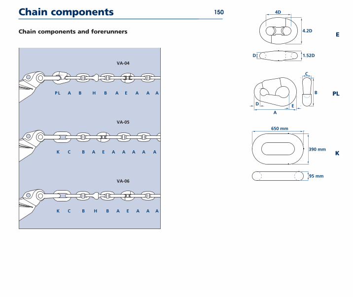
Mooring components
A typical mooring system can be divided in three different components the
mooring line the connectors and the anchor point
Mooring line
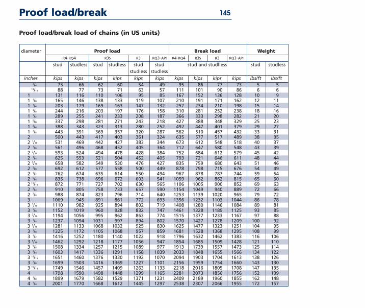
ChainThe most common product used for mooring lines is chain which is available
in different diameters and grades Two different designs of chain are used
frequently studlink and studless chain The studlink chain is most common-
ly used for moorings that have to be reset numerous times during their life-
time for instance semi-submersibles while studless link chain is often used
for permanent moorings (FPSOs buoys FSOs) A chain mooring line can be
terminated in either a common link or an end link (fig 1-03)
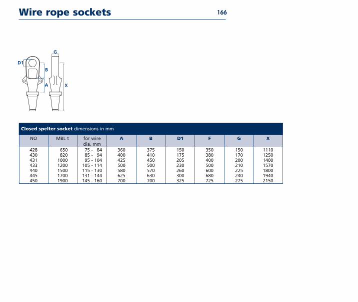
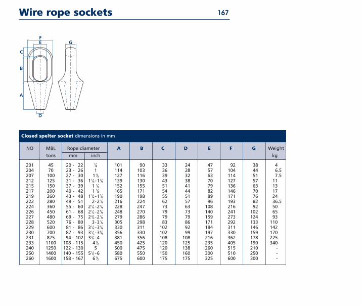
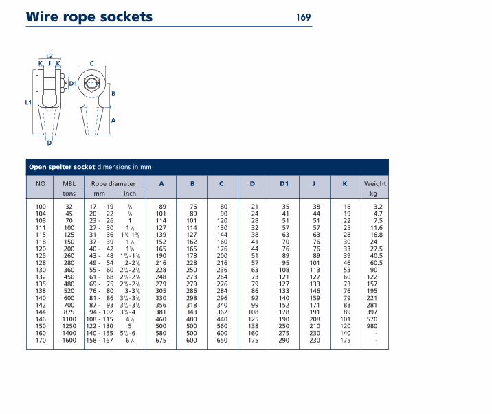
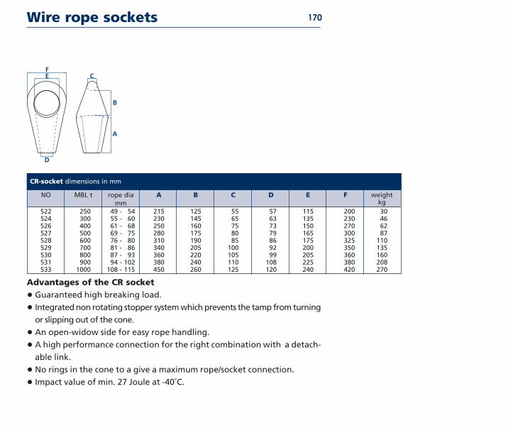
Wire ropeWhen compared to chain wire rope has a lower weight than chain for the
same breaking load and a higher elasticity Common wire ropes used in off-
shore mooring lines are six strand and spiral strand The wire rope is termi-
nated with a socket (for instance open spelter closed spelter CR) for con-
nection to the other components in the mooring system Generally wire
rope is more prone to damage and corrosion than chain (fig 1-04)
Synthetic fibre ropeA recent development is the use of synthetic fibre ropes as mooring line
Typical materials that can be used are polyester and high modulus polyeth-
ylene (Dyneema) The major advantage of synthetic fibre ropes is the light
weight of the material and the high elasticity The synthetic fibre rope is
generally terminated with a special spool and shackle for connection to the
other components in the mooring system
8
Mooring components
fig 1-05
fig 1-06
fig 1-07
fig 1-08
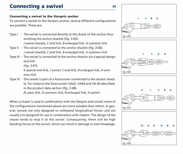
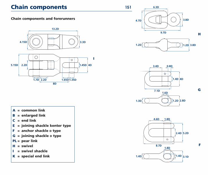
Connectors
ShacklesThe shackle is a connector that is very common in the offshore industry It
consists of a bow which is closed by a pin Many different types of shackles
are available depending on the application The shackle can be used in
both temporary and permanent moorings (fig 1-05)
Connecting link kenter typeThe connecting link kenter type is most commonly used for the connection
of two pieces of chain mooring line where the terminations of the two
pieces have the same dimensions The connecting link kenter type has the
same outside length as a chain link of the same diameter Generally
connecting links kenter type are not used in permanent mooring
systems as they have a shorter fatigue life than the chain (fig 1-06)
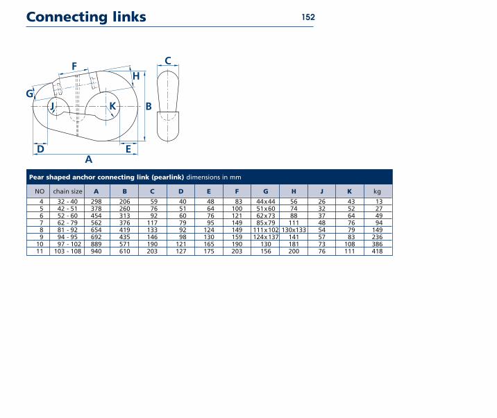
Connecting link pear shapedThe pear shaped connecting link is similar to the connecting link kenter
type except that it is used for the connection of two pieces of mooring line
with terminations that have different dimensions Like the connecting link
kenter type the pear shaped connecting links are not used in permanent
mooring systems (fig 1-07)
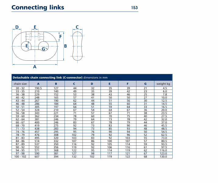
Connecting link c typeLike the connecting link kenter type the connecting link c type is used for
the connection of two pieces of mooring line with terminations that have
the same dimensions The major difference between the kenter type and
the c type is the way that the connector is opened and closed This connec-
tor is generally not used in permanent moorings (fig 1-08)
9
Mooring components
SwivelsA swivel is used in a mooring system generally of a temporary type to
relieve the twist and torque that builds up in the mooring line The swivel is
often placed a few links from the anchor point although it can also be
placed between a section of chain and a section of wire rope There are
many different types of swivels available although a disadvantage of most
common swivels is that they may not function while under load which is
caused by high friction inside the turning mechanism A new development is
swivels that are capable of swivelling under load due to special bearing sur-
faces inside the mechanism (fig 1-09)
Anchoring point
Dead weightThe dead weight is probably the oldest anchor in existence The holding
capacity is generated by the weight of the material used and partly by the
friction between the dead weight and the seabed Common materials in use
today for dead weights are steel and concrete (fig 1-10)
fig 1-10
13
fig 1-09
13
10
Mooring components
fig 1-12
13
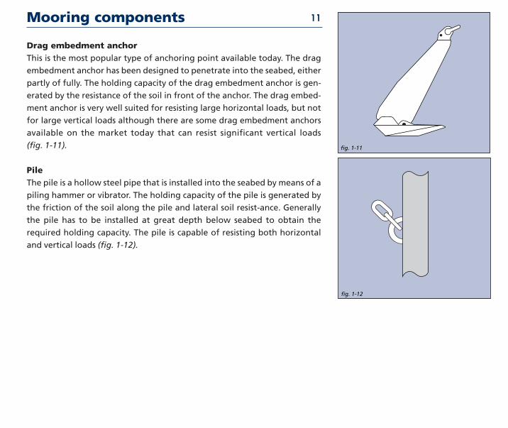
Drag embedment anchorThis is the most popular type of anchoring point available today The drag
embedment anchor has been designed to penetrate into the seabed either
partly of fully The holding capacity of the drag embedment anchor is gen-
erated by the resistance of the soil in front of the anchor The drag embed-
ment anchor is very well suited for resisting large horizontal loads but not
for large vertical loads although there are some drag embedment anchors
available on the market today that can resist significant vertical loads
(fig 1-11)
PileThe pile is a hollow steel pipe that is installed into the seabed by means of a
piling hammer or vibrator The holding capacity of the pile is generated by
the friction of the soil along the pile and lateral soil resist-ance Generally
the pile has to be installed at great depth below seabed to obtain the
required holding capacity The pile is capable of resisting both horizontal
and vertical loads (fig 1-12)
fig 1-11
13
11
Mooring components
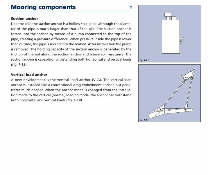
Suction anchorLike the pile the suction anchor is a hollow steel pipe although the diame-
ter of the pipe is much larger than that of the pile The suction anchor is
forced into the seabed by means of a pump connected to the top of the
pipe creating a pressure difference When pressure inside the pipe is lower
than outside the pipe is sucked into the seabed After installation the pump
is removed The holding capacity of the suction anchor is generated by the
friction of the soil along the suction anchor and lateral soil resistance The
suction anchor is capable of withstanding both horizontal and vertical loads
(fig 1-13)
Vertical load anchorA new development is the vertical load anchor (VLA) The vertical load
anchor is installed like a conventional drag embedment anchor but pene-
trates much deeper When the anchor mode is changed from the installa-
tion mode to the vertical (normal) loading mode the anchor can withstand
both horizontal and vertical loads (fig 1-14)
fig 1-13
13
fig 1-14
13
12
History of drag embedment anchorsHistory traces the use of anchors to China as far back as 2000 BC though it is quite probable that they
were used prior to this At that time the general tendency was to use large stones baskets of stones
bags of sand or even logs of wood loaded with lead which were then fastened to lines It was this
weight as well as a certain degree of friction on the bottom which secured a vessel in position
With the introduction of iron into anchor construction teeth or flukes were built on the anchor
allowing penetration into the seabed thus offering additional stability Yet these primitive
anchors were of poor construction and often broke under pressure Curved arms were intro-
duced in 1813 and from 1852 the so-called lsquoAdmiralty Anchorrsquo was used for ships of the Royal
Navy Another refinement in the 19th century was the elimination of the stock the crosspiece at
the top of an anchor which ensured that the positioning of the anchor would allow the flukes to
penetrate the soil A stockless anchor was invented in 1821 and became popular primarily as a
result of the ease of handling and stowing qualities still valued today
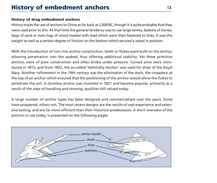
A large number of anchor types has been designed and commercialised over the years Some
have prospered others not The most recent designs are the results of vast experience and exten-
sive testing and are far more efficient than their historical predecessors A short overview of the
anchors in use today is presented on the following pages
History of embedment anchors 13
anchor shackle
shank
fluke
stabilisers
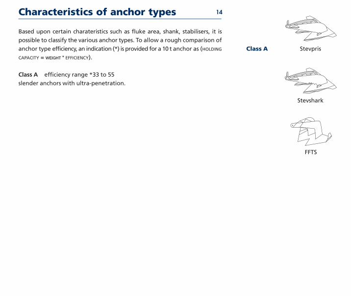
Based upon certain charateristics such as fluke area shank stabilisers it is
possible to classify the various anchor types To allow a rough comparison of
anchor type efficiency an indication () is provided for a 10 t anchor as (HOLDING
CAPACITY = WEIGHT EFFICIENCY)
Class A efficiency range 33 to 55
slender anchors with ultra-penetration
Characteristics of anchor types
StevprisClass A
Stevshark
FFTS
14
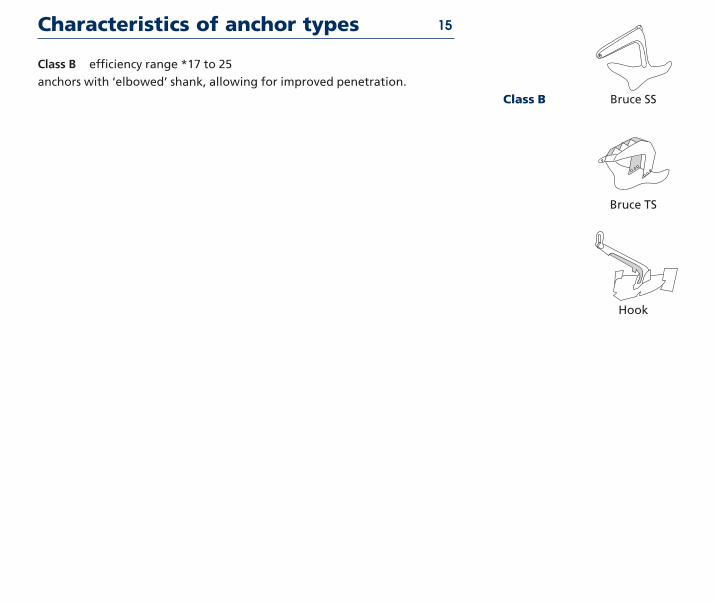
Class B efficiency range 17 to 25
anchors with lsquoelbowedrsquo shank allowing for improved penetration
Characteristics of anchor types
Bruce TS
Hook
Bruce SSClass B
15
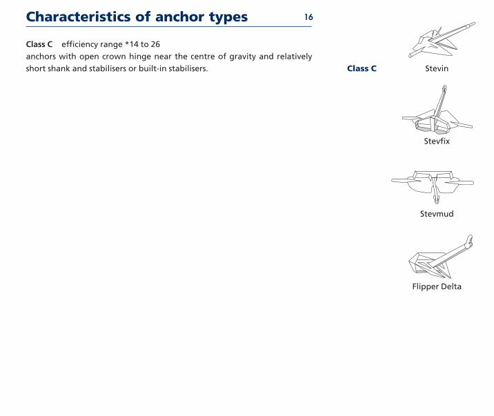
Class C efficiency range 14 to 26
anchors with open crown hinge near the centre of gravity and relatively
short shank and stabilisers or built-in stabilisers
Characteristics of anchor types
Stevfix
Stevmud
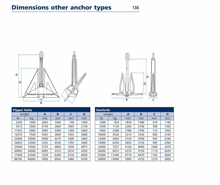
Flipper Delta
StevinClass C
16
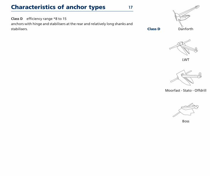
Class D efficiency range 8 to 15
anchors with hinge and stabilisers at the rear and relatively long shanks and
stabilisers
Characteristics of anchor types
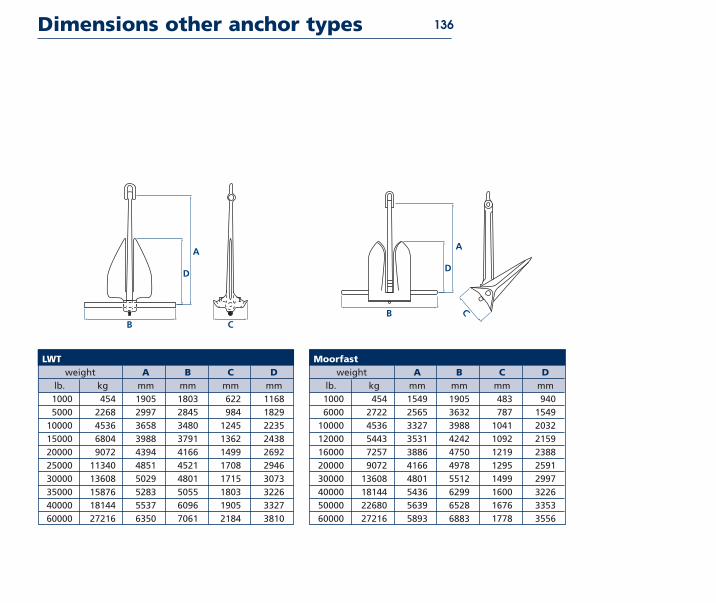
LWT
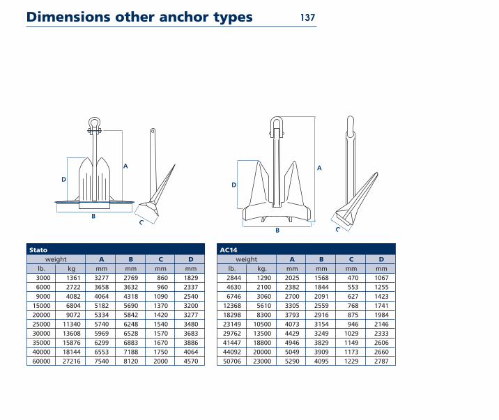
Moorfast - Stato - Offdrill
Boss
DanforthClass D
17
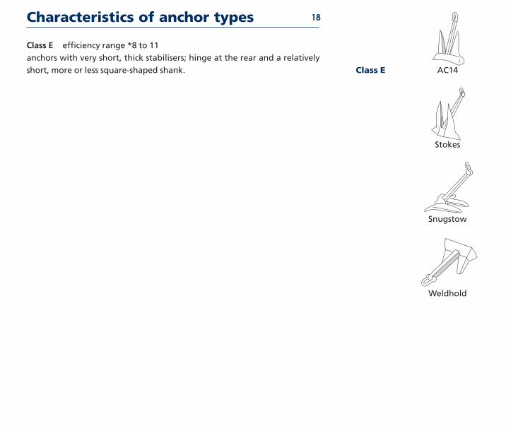
Class E efficiency range 8 to 11
anchors with very short thick stabilisers hinge at the rear and a relatively
short more or less square-shaped shank
Characteristics of anchor types
Stokes
Snugstow
Weldhold
AC14Class E
18
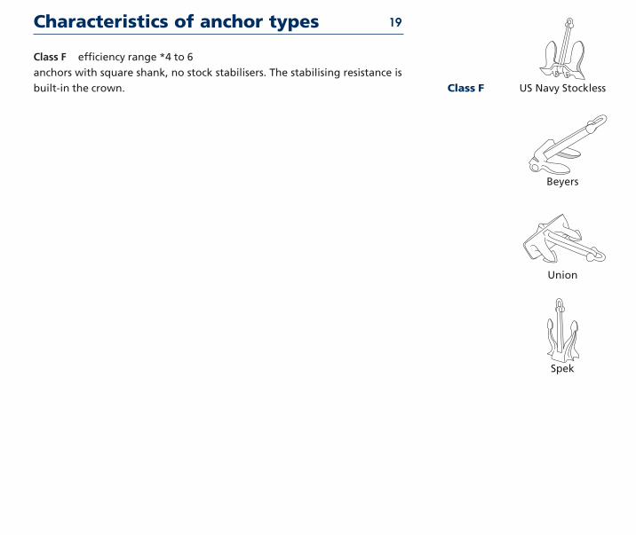
Class F efficiency range 4 to 6
anchors with square shank no stock stabilisers The stabilising resistance is
built-in the crown
Characteristics of anchor types
Beyers
Union
Spek
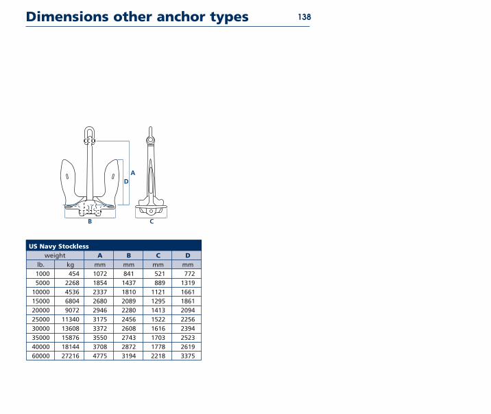
US Navy StocklessClass F
19
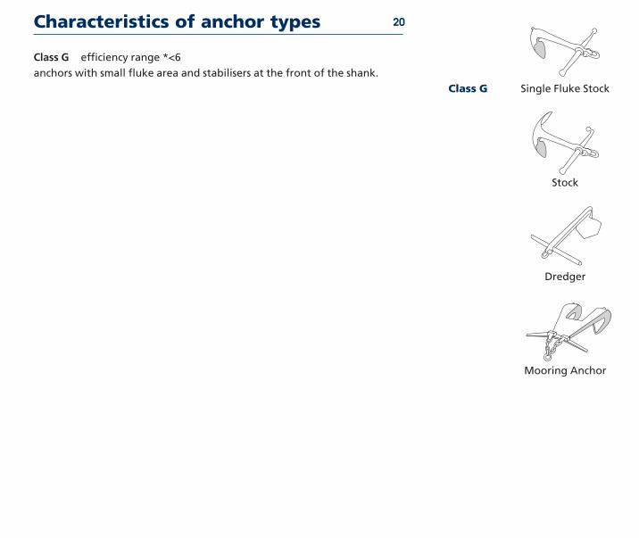
Class G efficiency range lt6
anchors with small fluke area and stabilisers at the front of the shank
Characteristics of anchor types
Stock
Dredger
Mooring Anchor
Single Fluke StockClass G
20
History of vryhof anchor designs
A brief chronological summary of the types of anchors vryhof has designed
for use in the offshore and dredging industries
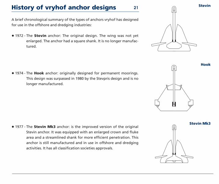
bull 1972 - The Stevin anchor The original design The wing was not yet
enlarged The anchor had a square shank It is no longer manufac-
tured
bull 1974 - The Hook anchor originally designed for permanent moorings
This design was surpassed in 1980 by the Stevpris design and is no
longer manufactured
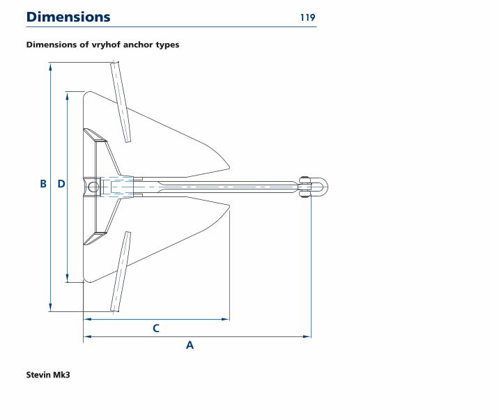
bull 1977 - The Stevin Mk3 anchor is the improved version of the original
Stevin anchor It was equipped with an enlarged crown and fluke
area and a streamlined shank for more efficient penetration This
anchor is still manufactured and in use in offshore and dredging
activities It has all classification societies approvals
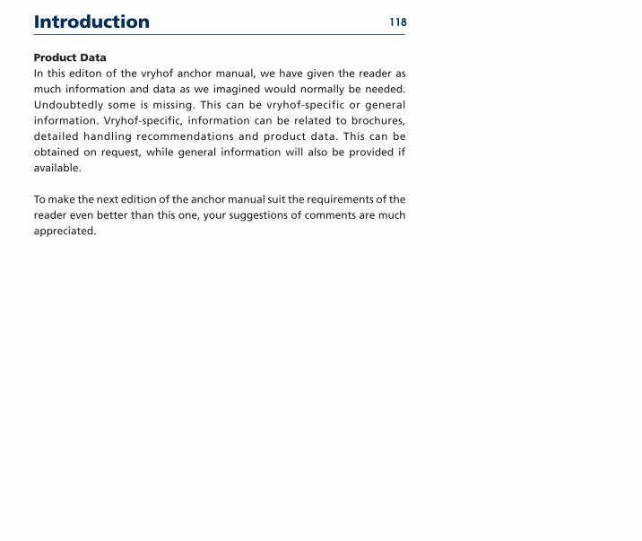
Stevin
Hook
Stevin Mk3
21
History of vryhof anchor designs
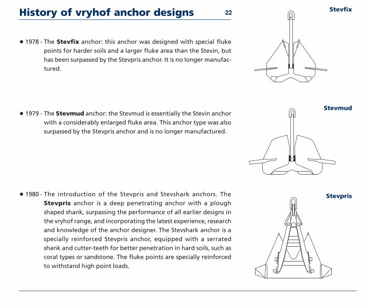
bull 1978 - The Stevfix anchor this anchor was designed with special fluke
points for harder soils and a larger fluke area than the Stevin but
has been surpassed by the Stevpris anchor It is no longer manufac-
tured
bull 1979 - The Stevmud anchor the Stevmud is essentially the Stevin anchor
with a considerably enlarged fluke area This anchor type was also
surpassed by the Stevpris anchor and is no longer manufactured
bull 1980 - The introduction of the Stevpris and Stevshark anchors The
Stevpris anchor is a deep penetrating anchor with a plough
shaped shank surpassing the performance of all earlier designs in
the vryhof range and incorporating the latest experience research
and knowledge of the anchor designer The Stevshark anchor is a
specially reinforced Stevpris anchor equipped with a serrated
shank and cutter-teeth for better penetration in hard soils such as
coral types or sandstone The fluke points are specially reinforced
to withstand high point loads
Stevmud
Stevpris
Stevfix22
History of vryhof anchor designs
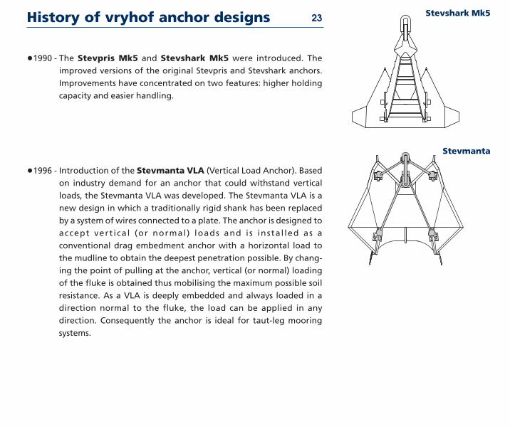
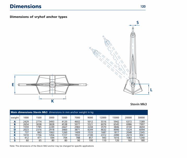
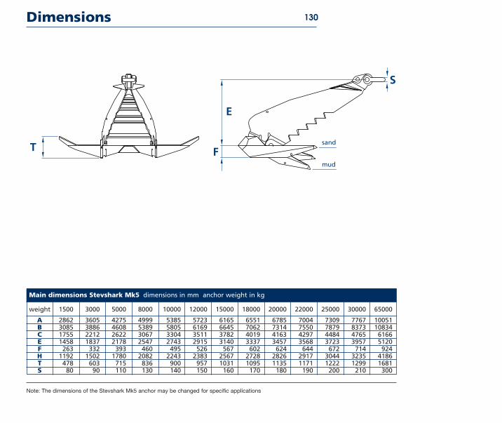
bull1990 - The Stevpris Mk5 and Stevshark Mk5 were introduced The
improved versions of the original Stevpris and Stevshark anchors
Improvements have concentrated on two features higher holding
capacity and easier handling
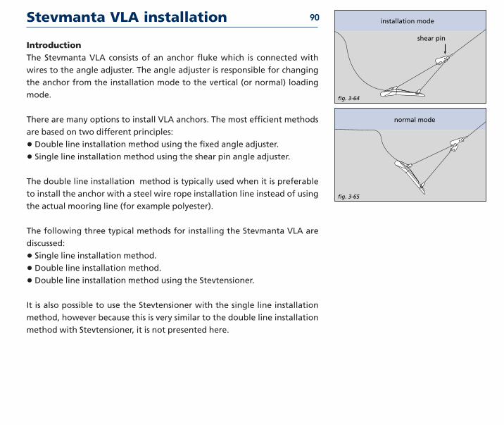
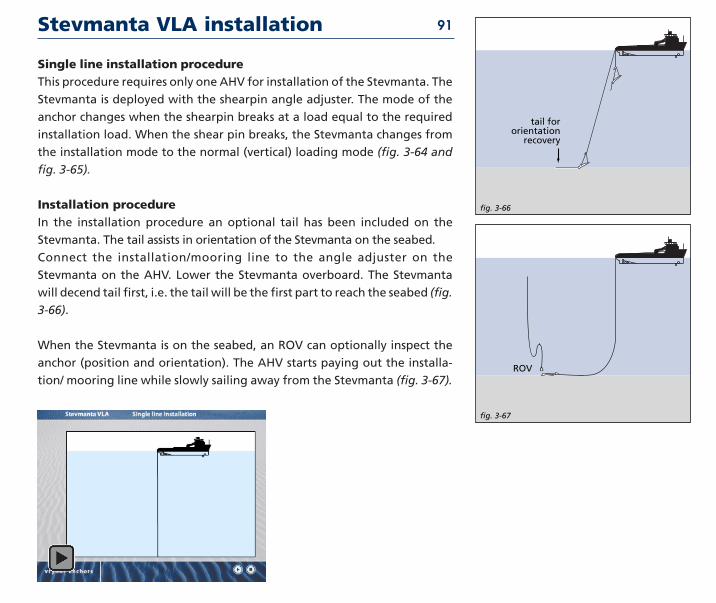
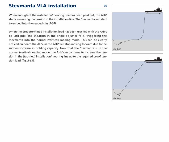
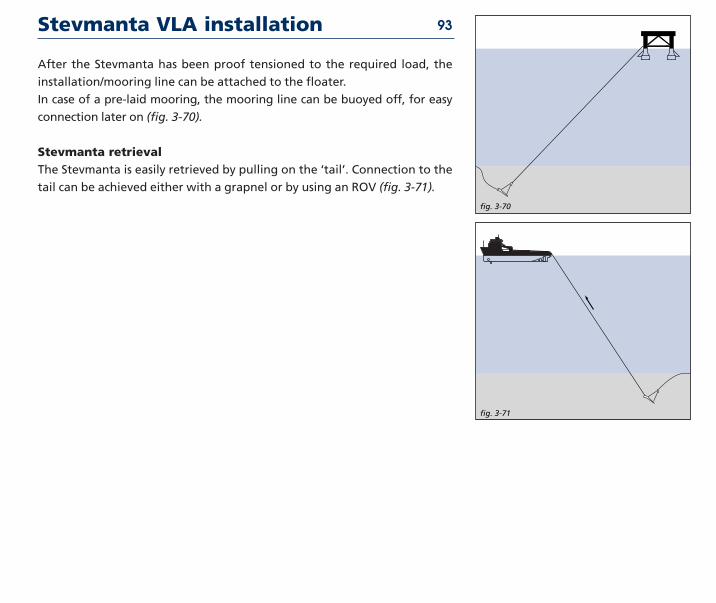
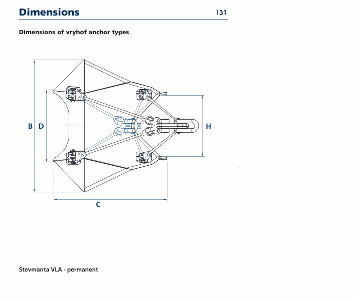
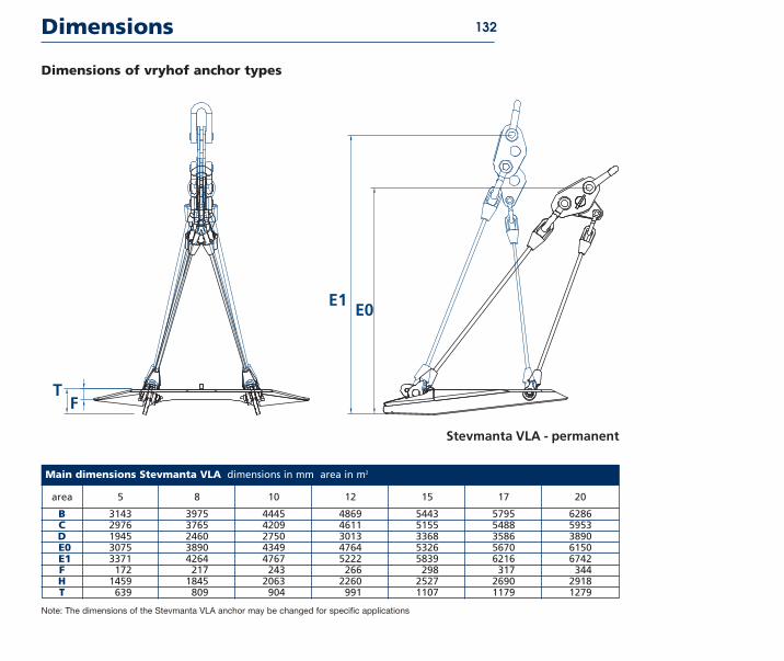
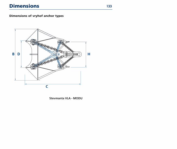
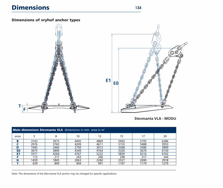
bull1996 - Introduction of the Stevmanta VLA (Vertical Load Anchor) Based
on industry demand for an anchor that could withstand vertical
loads the Stevmanta VLA was developed The Stevmanta VLA is a
new design in which a traditionally rigid shank has been replaced
by a system of wires connected to a plate The anchor is designed to
accept vert ical (or normal) loads and is instal led as a
conventional drag embedment anchor with a horizontal load to
the mudline to obtain the deepest penetration possible By chang-
ing the point of pulling at the anchor vertical (or normal) loading
of the fluke is obtained thus mobilising the maximum possible soil
resistance As a VLA is deeply embedded and always loaded in a
direction normal to the fluke the load can be applied in any
direction Consequently the anchor is ideal for taut-leg mooring
systems
Stevshark Mk5
Stevmanta
23
Theory
2
TheoryAnchor design used to be based on practical experience of the anchor man-
ufacturer only Nowadays science has become a major factor in the design
process complementing the experience of the anchor manufacturer Based
on test results both in the laboratory and in the field a much better under-
standing of anchor behaviour has been achieved
The performance of an anchor is influenced by many different parameters
of which the following are only a few fluke area and design shank design
soil conditions load conditions type of mooring line
This chapter presents a short overview of how these parameters influence
the performance of the anchor It is by no means complete but it will give a
better understanding of how an optimal anchor design can be achieved In
the last part of this chapter a few relevant test results are presented
Introduction 25
Anchor holding capacity 26
fig 2-02
fig 2-01
fig 2-03
fig 2-04
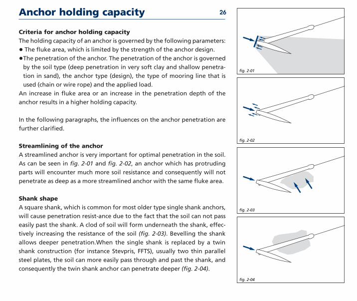
Criteria for anchor holding capacityThe holding capacity of an anchor is governed by the following parameters
bull The fluke area which is limited by the strength of the anchor design
bullThe penetration of the anchor The penetration of the anchor is governedby the soil type (deep penetration in very soft clay and shallow penetra-
tion in sand) the anchor type (design) the type of mooring line that is
used (chain or wire rope) and the applied load
An increase in fluke area or an increase in the penetration depth of the
anchor results in a higher holding capacity
In the following paragraphs the influences on the anchor penetration are
further clarified
Streamlining of the anchorA streamlined anchor is very important for optimal penetration in the soil
As can be seen in fig 2-01 and fig 2-02 an anchor which has protruding
parts will encounter much more soil resistance and consequently will not
penetrate as deep as a more streamlined anchor with the same fluke area
Shank shapeA square shank which is common for most older type single shank anchors
will cause penetration resist-ance due to the fact that the soil can not pass
easily past the shank A clod of soil will form underneath the shank effec-
tively increasing the resistance of the soil (fig 2-03) Bevelling the shank
allows deeper penetrationWhen the single shank is replaced by a twin
shank construction (for instance Stevpris FFTS) usually two thin parallel
steel plates the soil can more easily pass through and past the shank and
consequently the twin shank anchor can penetrate deeper (fig 2-04)
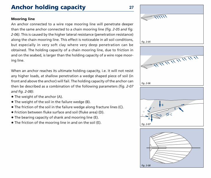
Mooring lineAn anchor connected to a wire rope mooring line will penetrate deeper
than the same anchor connected to a chain mooring line (fig 2-05 and fig
2-06) This is caused by the higher lateral resistance (penetration resistance)
along the chain mooring line This effect is noticeable in all soil conditions
but especially in very soft clay where very deep penetration can be
obtained The holding capacity of a chain mooring line due to friction in
and on the seabed is larger than the holding capacity of a wire rope moor-
ing line
When an anchor reaches its ultimate holding capacity ie it will not resist
any higher loads at shallow penetration a wedge shaped piece of soil (in
front and above the anchor) will fail The holding capacity of the anchor can
then be described as a combination of the following parameters (fig 2-07
and fig 2-08)
bull The weight of the anchor (A)
bull The weight of the soil in the failure wedge (B)
bull The friction of the soil in the failure wedge along fracture lines (C)
bull Friction between fluke surface and soil (fluke area) (D)
bull The bearing capacity of shank and mooring line (E)
bull The friction of the mooring line in and on the soil (E)
Anchor holding capacity 27
fig 2-05
fig 2-06
fig 2-07
A
B
C
E
D
fig 2-08
Criteria for good anchor design
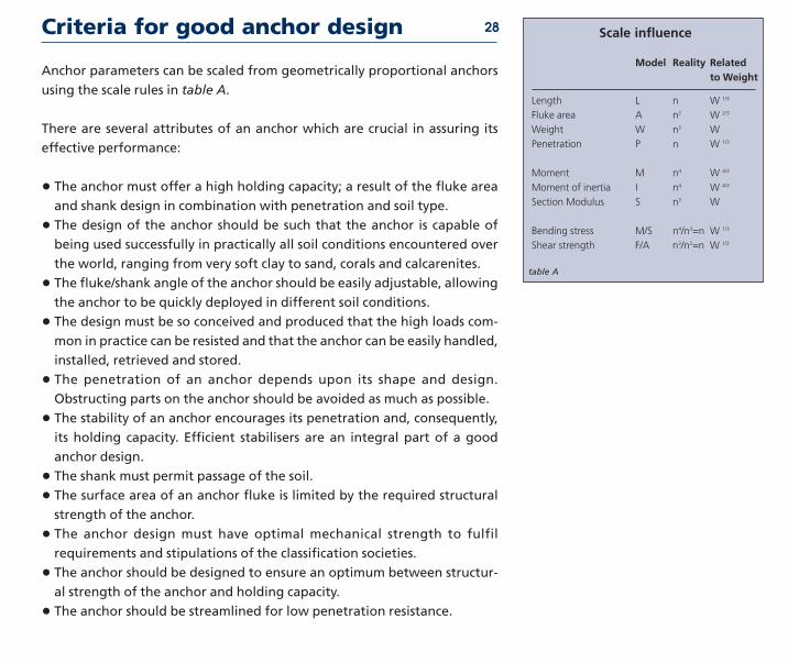
Anchor parameters can be scaled from geometrically proportional anchors
using the scale rules in table A
There are several attributes of an anchor which are crucial in assuring its
effective performance
bull The anchor must offer a high holding capacity a result of the fluke area
and shank design in combination with penetration and soil type
bull The design of the anchor should be such that the anchor is capable of
being used successfully in practically all soil conditions encountered over
the world ranging from very soft clay to sand corals and calcarenites
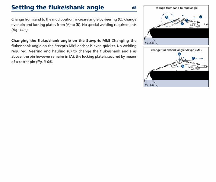
bull The flukeshank angle of the anchor should be easily adjustable allowing
the anchor to be quickly deployed in different soil conditions
bull The design must be so conceived and produced that the high loads com-
mon in practice can be resisted and that the anchor can be easily handled
installed retrieved and stored
bull The penetration of an anchor depends upon its shape and design
Obstructing parts on the anchor should be avoided as much as possible
bull The stability of an anchor encourages its penetration and consequently
its holding capacity Efficient stabilisers are an integral part of a good
anchor design
bull The shank must permit passage of the soil
bull The surface area of an anchor fluke is limited by the required structural
strength of the anchor
bull The anchor design must have optimal mechanical strength to fulfil
requirements and stipulations of the classification societies
bull The anchor should be designed to ensure an optimum between structur-
al strength of the anchor and holding capacity
bull The anchor should be streamlined for low penetration resistance
28
table A
Scale influence
Model Reality Related to Weight
Length L n W 13
Fluke area A n2 W 23
Weight W n3 W
Penetration P n W 13
Moment M n4 W 43
Moment of iner tia I n4 W 43
Section Modulus S n3 W
Bend ing stress MS n4n3=n W 13
Shear strength FA n3n2=n W 13
Aspects of soil in anchor design 29
Aspects of soil mechanics in anchor designUntil the nineteen seventies anchor design was largely an empirical process
There was not much science involved more use of experience It is not easy
for instance to calculate the Ultimate Holding Capacity (UHC) of an anchor
from the commonly known soil mechanics formulas The main problem is
the prediction of the volume of soil mobilised by the anchor To a large
degree it is this volume which determines the UHC Detailed understanding
of soil characteristics and behaviour is essential in the anchor design
process and of increasing benefit in handling at sea It is this understanding
which is the hallmark of a competent anchor designer and builder
For anchor design and installation the availability of good soil data is of
utmost importance as the soil is of great influence on anchor behaviour The
following are influenced by the soil conditions encountered
Anchor type - some anchors are more suited for soft soil conditions (soft
clay) while others are more suited for hard soils (sand and hard clays)
although there are a number of anchor types on the market that are suited
for most soil conditions encountered
Holding capacity - in hard soil like sand and hard clay the maximum
attainable ultimate holding capacity with a certain anchor type and size is
higher than the attainable ultimate holding capacity in very soft clay
Penetration and drag - in very soft clay the anchor will penetrate deeper
than in harder soil like sand As a consequence the drag length of the
anchor will also be longer in very soft clay than in hard soil
Retrieval forces - when an anchor is installed in very soft clay the required
retrieval forces will be higher than in hard soil like sand For example in
very soft clay the required retrieval force of an anchor can be equal to 80-
90 of the installation load while in hard soil (sand) the retrieval force
might only be 20-30 of the installation load
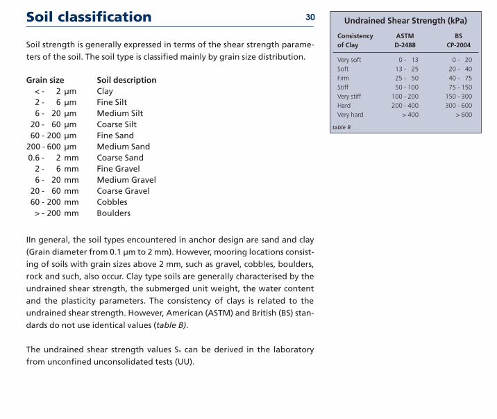
Soil classification 30 Undrained Shear Strength (kPa)
Consistency ASTM BSof Clay D-2488 CP-2004
Very soft 0 - 13 0 - 20
Soft 13 - 25 20 - 40
Firm 25 - 50 40 - 75
Stiff 50 - 100 75 - 150
Very stiff 100 - 200 150 - 300
Hard 200 - 400 300 - 600
Very hard gt 400 gt 600
table B
Soil strength is generally expressed in terms of the shear strength parame-
ters of the soil The soil type is classified mainly by grain size distribution
Grain size Soil descrip tionlt - 2 microm Clay2 - 6 microm Fine Silt6 - 20 microm Medium Silt
20 - 60 microm Coarse Silt60 - 200 microm Fine Sand200 - 600 microm Medium Sand06 - 2 mm Coarse Sand2 - 6 mm Fine Gravel6 - 20 mm Medium Gravel
20 - 60 mm Coarse Gravel60 - 200 mm Cobblesgt - 200 mm Boulders
IIn general the soil types encountered in anchor design are sand and clay
(Grain diameter from 01 microm to 2 mm) However mooring locations consist-
ing of soils with grain sizes above 2 mm such as gravel cobbles boulders
rock and such also occur Clay type soils are generally characterised by the
undrained shear strength the submerged unit weight the water content
and the plasticity parameters The consistency of clays is related to the
undrained shear strength However American (ASTM) and British (BS) stan-
dards do not use identical values (table B)
The undrained shear strength values Su can be derived in the laboratory
from unconfined unconsolidated tests (UU)
Soil classification 31
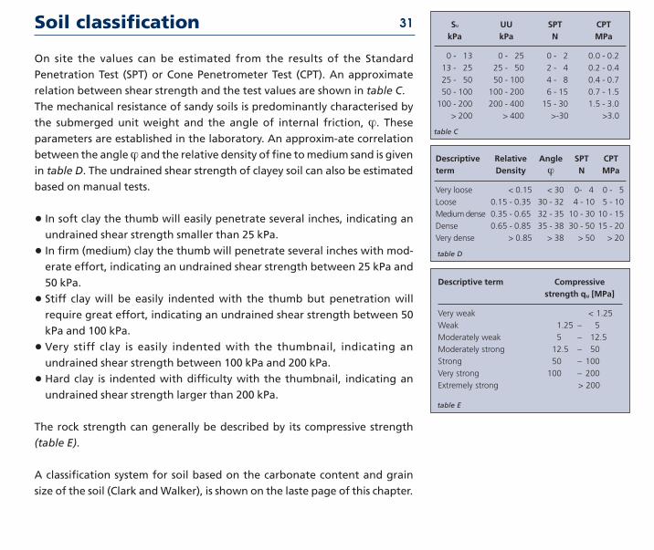
On site the values can be estimated from the results of the Standard
Penetration Test (SPT) or Cone Penetrometer Test (CPT) An approximate
relation between shear strength and the test values are shown in table C
The mechanical resistance of sandy soils is predominantly characterised by
the submerged unit weight and the angle of internal friction ϕ Theseparameters are established in the laboratory An approxim-ate correlation
between the angle ϕ and the relative density of fine to medium sand is given
in table D The undrained shear strength of clayey soil can also be estimated
based on manual tests
bull In soft clay the thumb will easily penetrate several inches indicating an
undrained shear strength smaller than 25 kPa
bull In firm (medium) clay the thumb will penetrate several inches with mod-
erate effort indicating an undrained shear strength between 25 kPa and
50 kPa
bull Stiff clay will be easily indented with the thumb but penetration will
require great effort indicating an undrained shear strength between 50
kPa and 100 kPa
bull Very stiff clay is easily indented with the thumbnail indicating an
undrained shear strength between 100 kPa and 200 kPa
bull Hard clay is indented with difficulty with the thumbnail indicating an
undrained shear strength larger than 200 kPa
The rock strength can generally be described by its compressive strength
(table E)
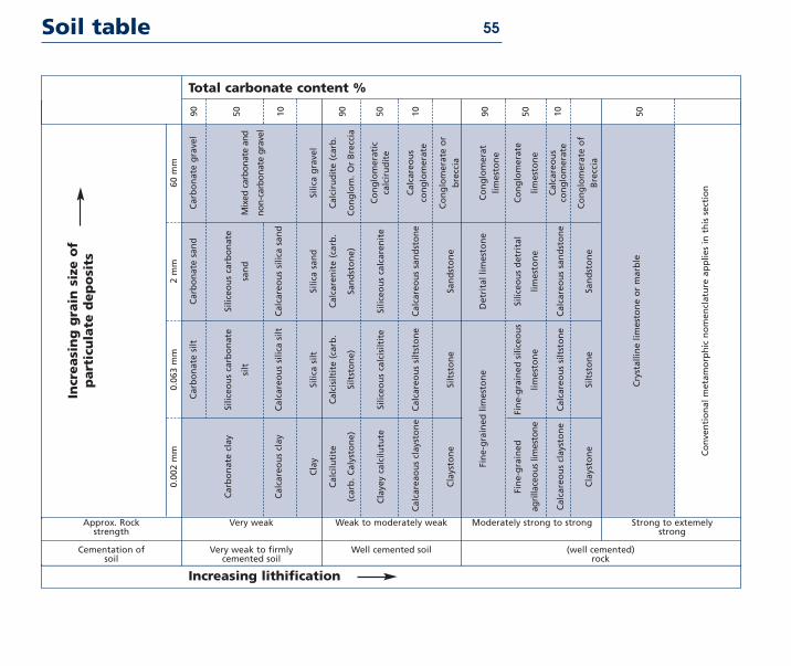
A classification system for soil based on the carbonate content and grain
size of the soil (Clark and Walker) is shown on the laste page of this chapter
Su UU SPT CPTkPa kPa N MPa
0 - 13 0 - 25 0 - 2 00 - 02
13 - 25 25 - 50 2 - 4 02 - 04
25 - 50 50 - 100 4 - 8 04 - 07
50 - 100 100 - 200 6 - 15 07 - 15
100 - 200 200 - 400 15 - 30 15 - 30
gt 200 gt 400 gt-30 gt30
table C
Descriptive Relative Angle SPT CPTterm Density ϕ N MPa
Very loose lt 015 lt 30 0- 4 0 - 5
Loose 015 - 035 30 - 32 4 - 10 5 - 10
Medi um dense 035 - 065 32 - 35 10 - 30 10 - 15
Dense 065 - 085 35 - 38 30 - 50 15 - 20
Very dense gt 085 gt 38 gt 50 gt 20
Descriptive term Compressivestrength qu [MPa]
Very weak lt 125
Weak 125 ndash 5
Moderately weak 5 ndash 125
Moderately strong 125 ndash 50
Strong 50 ndash 100
Very strong 100 ndash 200
Extremely strong gt 200
table D
table E
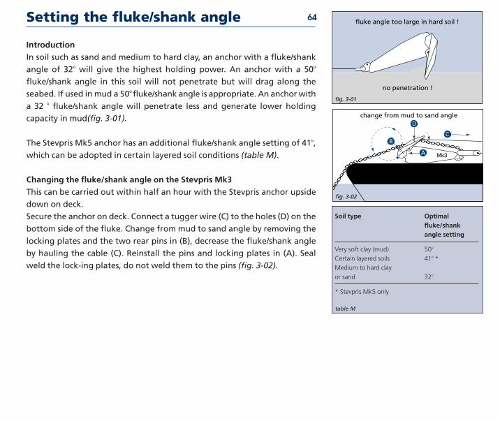
Flukeshank angle
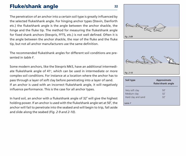
The penetration of an anchor into a certain soil type is greatly influenced by
the selected flukeshank angle For hinging anchor types (Stevin Danforth
etc) the flukeshank angle is the angle between the anchor shackle the
hinge and the fluke tip The method for measuring the flukeshank angle
for fixed shank anchors (Stevpris FFTS etc) is not well defined Often it is
the angle between the anchor shackle the rear of the fluke and the fluke
tip but not all anchor manufacturers use the same definition
The recommended flukeshank angles for different soil conditions are pre-
sented in table F
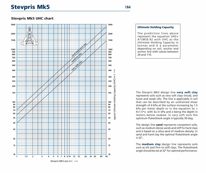
Some modern anchors like the Stevpris Mk5 have an additional intermedi-
ate flukeshank angle of 41o which can be used in intermediate or more
complex soil conditions For instance at a location where the anchor has to
pass through a layer of soft clay before penetrating into a layer of sand
If an anchor is used with an incorrect flukeshank angle it will negatively
influence performance This is the case for all anchor types
In hard soil an anchor with a flukeshank angle of 320 will give the highest
holding power If an anchor is used with the flukeshank angle set at 500 the
anchor will fail to penetrate into the seabed and will begin to trip fall aside
and slide along the seabed (Fig 2-9 and 2-10)
32
fig 2-09
fig 2-10
Soil type Approximateflukeshank angle
Very soft clay 50˚
Medium clay 32˚
Hard clay and sand 32˚
table F
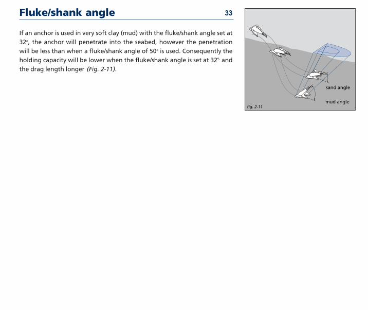
If an anchor is used in very soft clay (mud) with the flukeshank angle set at
32o the anchor will penetrate into the seabed however the penetration
will be less than when a flukeshank angle of 50o is used Consequently the
holding capacity will be lower when the flukeshank angle is set at 32o and
the drag length longer (Fig 2-11)
Flukeshank angle 33
fig 2-11
13
mud angle
sand angle
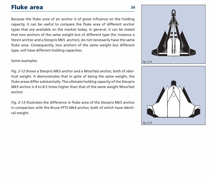
Because the fluke area of an anchor is of great influence on the holding
capacity it can be useful to compare the fluke area of different anchor
types that are available on the market today In general it can be stated
that two anchors of the same weight but of different type (for instance a
Stevin anchor and a Stevpris Mk5 anchor) do not necessarily have the same
fluke area Consequently two anchors of the same weight but different
type will have different holding capacities
Some examples
Fig 2-12 shows a Stevpris Mk5 anchor and a Moorfast anchor both of iden-
tical weight It demonstrates that in spite of being the same weight the
fluke areas differ substantially The ultimate holding capacity of the Stevpris
Mk5 anchor is 4 to 85 times higher than that of the same weight Moorfast
anchor
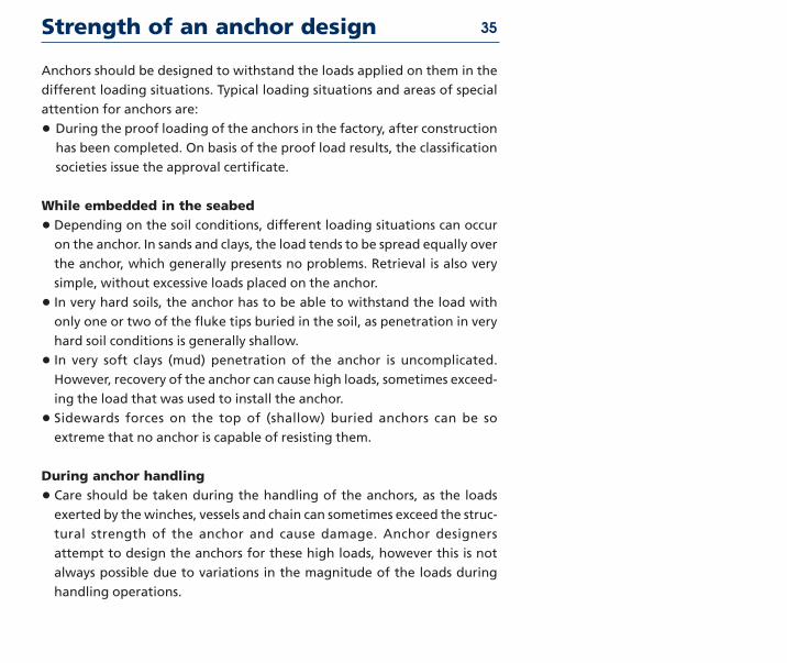
Fig 2-13 illustrates the difference in fluke area of the Stevpris Mk5 anchor
in comparison with the Bruce FFTS Mk4 anchor both of which have identi-
cal weight
Fluke area 34
fig 2-13
13
fig 2-12
13
Strength of an anchor design 35
Anchors should be designed to withstand the loads applied on them in the
different loading situations Typical loading situations and areas of special
attention for anchors are
bull During the proof loading of the anchors in the factory after construction
has been completed On basis of the proof load results the classification
societies issue the approval certificate
While embedded in the seabed
bull Depending on the soil conditions different loading situations can occur
on the anchor In sands and clays the load tends to be spread equally over
the anchor which generally presents no problems Retrieval is also very
simple without excessive loads placed on the anchor
bull In very hard soils the anchor has to be able to withstand the load with
only one or two of the fluke tips buried in the soil as penetration in very
hard soil conditions is generally shallow
bull In very soft clays (mud) penetration of the anchor is uncomplicated
However recovery of the anchor can cause high loads sometimes exceed-
ing the load that was used to install the anchor
bull Sidewards forces on the top of (shallow) buried anchors can be so
extreme that no anchor is capable of resisting them
During anchor handling
bull Care should be taken during the handling of the anchors as the loads
exerted by the winches vessels and chain can sometimes exceed the struc-
tural strength of the anchor and cause damage Anchor designers
attempt to design the anchors for these high loads however this is not
always possible due to variations in the magnitude of the loads during
handling operations
Strength of an anchor design 36
bull Large forces can be exerted on the anchor when high winch power is
used the anchor is caught on the anchor rack or caught behind the stern
roller of the AHV
bull The use of an improper anchorchaser combination When a chaser is used
that is either too small or too large the chaser could jam on the shank of
the anchor and cause damage
The strength of the Stevpris anchor is now more closely examined in the
light of the remarks made before
Strength of the shankThe prismatic shape of the Stevpris anchor not only ensures optimal pene-
tration of the soil but also guarantees maximum strength Although the
Stevpris design also has limitations it is one of the better designs to with-
stand sideward forces on the shank a frequent occurrence in practice
When using an anchor in very soft clay (mud) the bending moment on the
shank is low during the installation and when the anchor is in the soil
However during the breaking out of the anchor high bending moments
could be introduced in the shank due to the high retrieval forces required
in very soft clay In extremely sticky soils the breaking out force of the
anchor can rise to 80 or 90 of applied anchor load in certain instances
it can even exceed 100 To reduce these forces the breaking out proce-
dure is undertaken at low speed to allow time for the anchor to break out
Strength of an anchor design 37
Strength of the flukeThe strength of the fluke and especially the fluke points of an anchor are
very important when working in extremely hard soils such as coral lime-
stone and other rock types It is possible in such instances that the total
holding capacity of the anchor will have to be sustained by the fluke points
alone This means the structure must be strong enough to withstand
extreme bending forces Loading in normal soil conditions is not a problem
due to the fact that the load is equally spread over the fluke
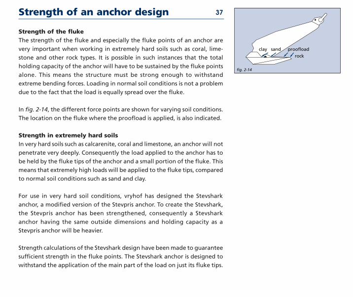
In fig 2-14 the different force points are shown for varying soil conditions
The location on the fluke where the proofload is applied is also indicated
Strength in extremely hard soilsIn very hard soils such as calcarenite coral and limestone an anchor will not
penetrate very deeply Consequently the load applied to the anchor has to
be held by the fluke tips of the anchor and a small portion of the fluke This
means that extremely high loads will be applied to the fluke tips compared
to normal soil conditions such as sand and clay
For use in very hard soil conditions vryhof has designed the Stevshark
anchor a modified version of the Stevpris anchor To create the Stevshark
the Stevpris anchor has been strengthened consequently a Stevshark
anchor having the same outside dimensions and holding capacity as a
Stevpris anchor will be heavier
Strength calculations of the Stevshark design have been made to guarantee
sufficient strength in the fluke points The Stevshark anchor is designed to
withstand the application of the main part of the load on just its fluke tips
fig 2-14
rock
proofloadclay sand
Strength of an anchor design 38
To promote penetration the Stevshark anchor has a serrated shank and can
be provided with cutter points on the fluke tips Ballast weight can also be
added inside the hollow flukes of the anchor up to 35 of the anchor
weight This is important when working in very hard soil where the anchor
weight pressing on the fluke tips promotes penetration ie increased bear-
ing pressure
The loads in a mooring system are caused by the wind waves and current
acting on the floater Depending on the location of the floater in the world
different metocean conditions will prevail In the table below some
extreme metocean conditions are presented for different areas
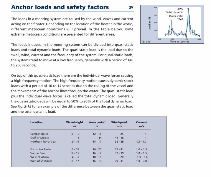
The loads induced in the mooring system can be divided into quasi-static
loads and total dynamic loads The quasi static load is the load due to the
swell wind current and the frequency of the system For quasi-static loads
the systems tend to move at a low frequency generally with a period of 140
to 200 seconds
On top of this quasi-static load there are the individ-ual wave forces causing
a high frequency motion The high frequency motion causes dynamic shock
loads with a period of 10 to 14 seconds due to the rolling of the vessel and
the movements of the anchor lines through the water The quasi-static load
plus the individual wave forces is called the total dynamic load Generally
the quasi-static loads will be equal to 50 to 90 of the total dynamic load
See Fig 2-15 for an example of the difference between the quasi-static load
and the total dynamic load
Anchor loads and safety factors
fig 2-15
4000
3000
2000
1000
08300 8400 8500 8600 8700 8800 9800
389513Total dynamic
Quasi static13234213
13
Load
in k
N
Time in seconds
Location Waveheight Wave period Windspeed Currentm s ms ms
Campos Basin 8 ndash 10 12 - 15 25 1Gulf of Mexico 11 14 44 - 48 1Northern North Sea 15 - 16 15 - 17 38 - 39 09ndash 12
Porcupine Basin 16 - 18 16 - 20 39 - 41 10 ndash 15Vorine Basin 14 - 15 16 - 17 37 - 39 10 ndash 15West of Africa 4 - 6 10 - 16 20 03 ndash 06West of Shetlands 15 - 17 16 - 19 39 - 41 10 ndash 30
39
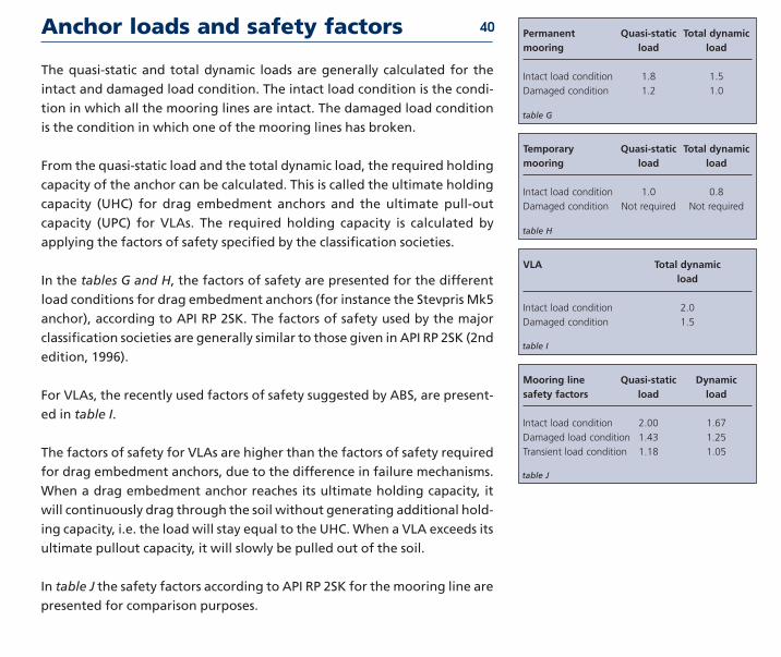
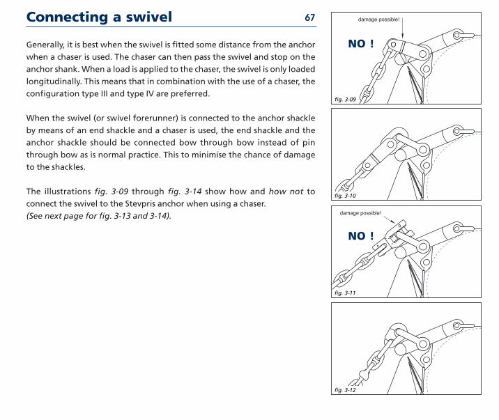
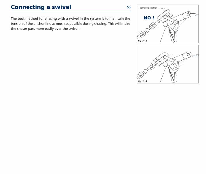
Anchor loads and safety factors
The quasi-static and total dynamic loads are generally calculated for the
intact and damaged load condition The intact load condition is the condi-
tion in which all the mooring lines are intact The damaged load condition
is the condition in which one of the mooring lines has broken
From the quasi-static load and the total dynamic load the required holding
capacity of the anchor can be calculated This is called the ultimate holding
capacity (UHC) for drag embedment anchors and the ultimate pull-out
capacity (UPC) for VLAs The required holding capacity is calculated by
applying the factors of safety specified by the classification societies
In the tables G and H the factors of safety are presented for the different
load conditions for drag embedment anchors (for instance the Stevpris Mk5
anchor) according to API RP 2SK The factors of safety used by the major
classification societies are generally similar to those given in API RP 2SK (2nd
edition 1996)
For VLAs the recently used factors of safety suggested by ABS are present-
ed in table I
The factors of safety for VLAs are higher than the factors of safety required
for drag embedment anchors due to the difference in failure mechanisms
When a drag embedment anchor reaches its ultimate holding capacity it
will continuously drag through the soil without generating additional hold-
ing capacity ie the load will stay equal to the UHC When a VLA exceeds its
ultimate pullout capacity it will slowly be pulled out of the soil
In table J the safety factors according to API RP 2SK for the mooring line are
presented for comparison purposes
40 Permanent Quasi-static Total dynamicmooring load load
Intact load condition 18 15
Damaged condition 12 10
Temporary Quasi-static Total dynamicmooring load load
Intact load condition 10 08
Damaged condition Not required Not required
VLA Total dynamicload
Intact load condition 20
Damaged condition 15
table G
table H
table I
Mooring line Quasi-static Dynamicsafety factors load load
Intact load condition 200 167
Damaged load condition 143 125
Transient load condition 118 105
table J
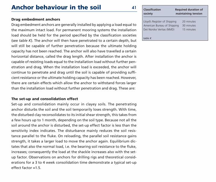
Drag embedment anchorsDrag embedment anchors are generally installed by applying a load equal to
the maximum intact load For permanent mooring systems the installation
load should be held for the period specified by the classification societies
(see table K) The anchor will then have penetrated to a certain depth but
will still be capable of further penetration because the ultimate holding
capacity has not been reached The anchor will also have travelled a certain
horizontal distance called the drag length After installation the anchor is
capable of resisting loads equal to the installation load without further pen-
etration and drag When the installation load is exceeded the anchor will
continue to penetrate and drag until the soil is capable of providing suffi-
cient resistance or the ultimate holding capacity has been reached However
there are certain effects which allow the anchor to withstand forces larger
than the installation load without further penetration and drag These are
The set-up and consolidation effectSet-up and consolidation mainly occur in clayey soils The penetrating
anchor disturbs the soil and the soil temporarily loses strength With time
the disturbed clay reconsolidates to its initial shear strength this takes from
a few hours up to 1 month depending on the soil type Because not all the
soil around the anchor is disturbed the set-up effect factor is less than the
sensitivity index indicates The disturbance mainly reduces the soil resis-
tance parallel to the fluke On reloading the parallel soil resistance gains
strength it takes a larger load to move the anchor again Equilibrium dic-
tates that also the normal load ie the bearing soil resistance to the fluke
increases consequently the load at the shackle increases also with the set-
up factor Observations on anchors for drilling rigs and theoretical consid-
erations for a 3 to 4 week consolidation time demonstrate a typical set-up
effect factor =15
Anchor behaviour in the soil 41 Classification Required duration ofsociety maintaining tension
Lloydrsquos Register of Shipping 20 minutes
American Bureau of Shipping 30 minutes
Det Norske Veritas (NMD) 15 minutes
table K
Anchor behaviour in the soil
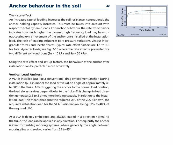
The rate effect An increased rate of loading increases the soil resistance consequently the
anchor holding capacity increases This must be taken into account with
respect to total dynamic loads For anchor behaviour the rate effect factor
indicates how much higher the dynamic high frequency load may be with-
out causing extra movement of the anchor once installed at the installation
load The rate of loading influences pore pressure variations viscous inter-
granular forces and inertia forces Typical rate effect factors are 11 to 13
for total dynamic loads see Fig 2-16 where the rate effect is presented for
two different soil conditions (Su = 10 kPa and Su = 50 kPa)
Using the rate effect and set-up factors the behaviour of the anchor after
installation can be predicted more accurately
Vertical Load AnchorsA VLA is installed just like a conventional drag embedment anchor During
installation (pull-in mode) the load arrives at an angle of approximately 45
to 500 to the fluke After triggering the anchor to the normal load position
the load always arrives perpendicular to the fluke This change in load direc-
tion generates 25 to 3 times more holding capacity in relation to the instal-
lation load This means that once the required UPC of the VLA is known the
required installation load for the VLA is also known being 33 to 40 of
the required UPC
As a VLA is deeply embedded and always loaded in a direction normal to
the fluke the load can be applied in any direction Consequently the anchor
is ideal for taut-leg mooring systems where generally the angle between
mooring line and seabed varies from 25 to 450
42
fig 2-16
0
12
11
1
09
080 200 400 600 800 1000
Time factor St
Rat
e ef
fect
fac
tor
Su=10 kPa Su=50 kPa
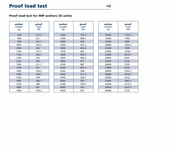
Proof loads anchors
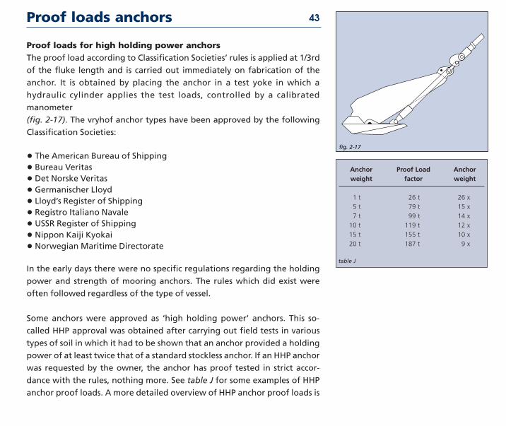
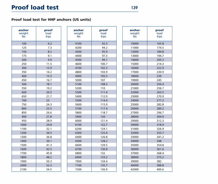
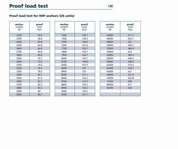
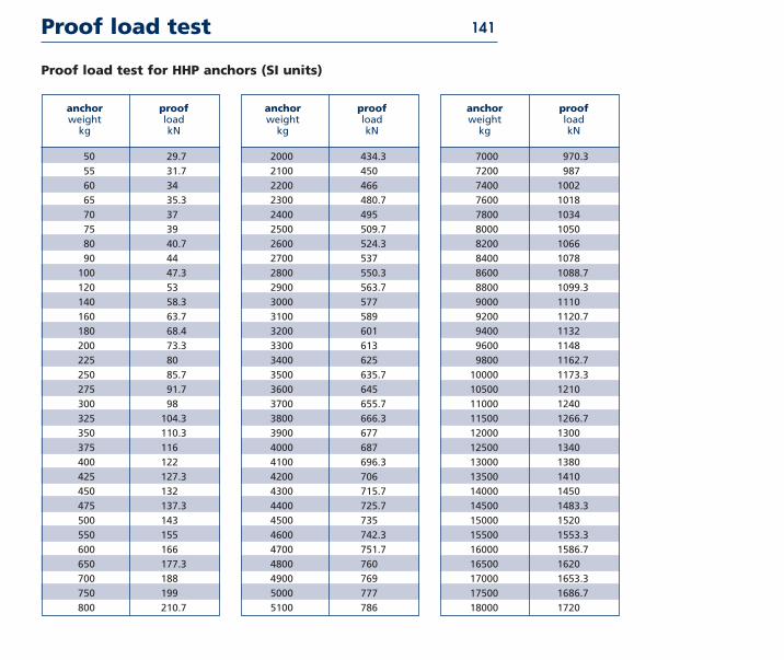
Proof loads for high holding power anchorsThe proof load according to Classification Societiesrsquo rules is applied at 13rd
of the fluke length and is carried out immediately on fabrication of the
anchor It is obtained by placing the anchor in a test yoke in which a
hydraulic cylinder applies the test loads controlled by a calibrated
manometer
(fig 2-17) The vryhof anchor types have been approved by the following
Classification Societies
bull The American Bureau of Shipping
bull Bureau Veritas
bull Det Norske Veritas
bull Germanischer Lloyd
bull Lloydrsquos Register of Shipping
bull Registro Italiano Navale
bull USSR Register of Shipping
bull Nippon Kaiji Kyokai
bull Norwegian Maritime Directorate
In the early days there were no specific regulations regarding the holding
power and strength of mooring anchors The rules which did exist were
often followed regardless of the type of vessel
Some anchors were approved as lsquohigh holding powerrsquo anchors This so-
called HHP approval was obtained after carrying out field tests in various
types of soil in which it had to be shown that an anchor provided a holding
power of at least twice that of a standard stockless anchor If an HHP anchor
was requested by the owner the anchor has proof tested in strict accor-
dance with the rules nothing more See table J for some examples of HHP
anchor proof loads A more detailed overview of HHP anchor proof loads is
fig 2-17
13
Anchor Proof Load Anchorweight fac tor weight
1 t 26 t 26 x
5 t 79 t 15 x
7 t 99 t 14 x
10 t 119 t 12 x
15 t 155 t 10 x
20 t 187 t 9 x
table J
43
Proof loads anchors
given in the product data section
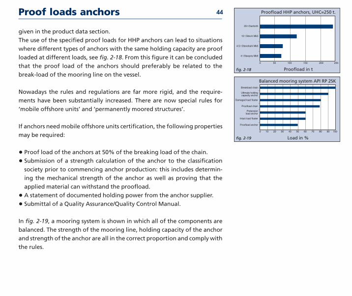
The use of the specified proof loads for HHP anchors can lead to situations
where different types of anchors with the same holding capacity are proof
loaded at different loads see fig 2-18 From this figure it can be concluded
that the proof load of the anchors should preferably be related to the
break-load of the mooring line on the vessel
Nowadays the rules and regulations are far more rigid and the require-
ments have been substantially increased There are now special rules for
lsquomobile offshore unitsrsquo and lsquopermanently moored structuresrsquo
If anchors need mobile offshore units certification the following properties
may be required
bull Proof load of the anchors at 50 of the breaking load of the chain
bull Submission of a strength calculation of the anchor to the classification
society prior to commencing anchor production this includes determin-
ing the mechanical strength of the anchor as well as proving that the
applied material can withstand the proofload
bull A statement of documented holding power from the anchor supplier
bull Submittal of a Quality AssuranceQuality Control Manual
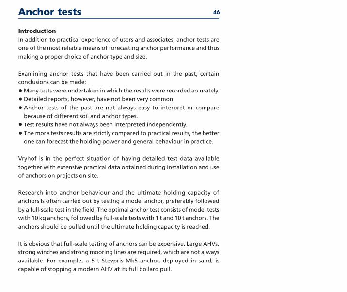
In fig 2-19 a mooring system is shown in which all of the components are
balanced The strength of the mooring line holding capacity of the anchor
and strength of the anchor are all in the correct proportion and comply with
the rules
44
fig 2-18
0 50 100 150 200 250
29 t Danforth
10 t Stevin Mk3
45 t Stevshark Mk5
4 t Stevpris Mk5
Proofload in t
Proofload HHP anchors UHC=250 t1313
fig 2-19
0 10 20 30 40 50 60 70 80 90 100
Breakload chain
Ultimate holdingcapacity anchor
Damaged load floater
Proofload chain
Pretensionload anchor
Intact load floater
Proofload anchor
Balanced mooring system API RP 2SK
Load in
Quality control 45
The application of more advanced and complex technology in anchor
construction has brought about requirements for a systematic approach to
quality Initiated by various authorities they are continuously refined and
followed up by operating companies such as vryhof anchor Like other
companies vryhof has become increasingly aware of the vital importance
of managerial aspects and their influence on the total quality-assurance
and control system
Design and fabrication of anchors for permanent moorings are in
accordance with the quality requirements of the Rules NSISO 9001 as
described in our Quality Assurance Manual Vryhof anchors obtained the
ISO 90012000 certificate No 29389-2008-AQ-NLD-RvA Rev1 issued by Det
Norske Veritas for lsquoDesign Manufacture of anchors and Sales of anchors
and mooring componentsrsquo
Quality control is maintained throughout production A compilation of
certificates is presented to a client upon completion of a project
Anchor tests
IntroductionIn addition to prac ti cal expe ri ence of users and asso ciates anchor tests are
one of the most reli able means of fore cast ing anchor per for mance and thus
mak ing a prop er choice of anchor type and size
Examining anchor tests that have been car ried out in the past cer tain
conclu sions can be made
bullMany tests were under tak en in which the results were record ed accu rate ly
bull Detailed reports how ev er have not been very com mon
bull Anchor tests of the past are not always easy to inter pret or com pare
because of dif fer ent soil and anchor types
bull Test results have not always been inter pret ed inde pen dent ly
bull The more tests results are strict ly com pared to prac ti cal results the bet ter
one can fore cast the hold ing power and gen er al beha vi our in prac tice
Vryhof is in the per fect sit u a tion of hav ing detailed test data avail able
togeth er with exten sive prac ti cal data obtained dur ing instal la tion and use
of anchors on pro jects on site
Research into anchor beha vi our and the ulti mate hold ing capac ity of
anchors is often car ried out by test ing a model anchor pref er ably fol lowed
by a full-scale test in the field The opti mal anchor test con sists of model tests
with 10 kg anchors fol lowed by full-scale tests with 1 t and 10 t anchors The
anchors should be pulled until the ulti mate hold ing capac ity is reached
It is obvi ous that full-scale test ing of anchors can be expen sive Large AHVs
strong winch es and strong moor ing lines are required which are not always
avail able For exam ple a 5 t Stevpris Mk5 anchor deployed in sand is
capable of stop ping a mod ern AHV at its full bol lard pull
46
Anchor tests 47
fig 2-20 Drag
Ho
ldin
g C
apac
ity A G B
C
D
E
F
Testing a 10 t Stevpris Mk5 anchor to its ulti mate hold ing capac ity in sand
would require a hor i zon tal pull ing capac ity of approx i mate ly 600 t
If anchor tests are to be com par able the test ing pro gram should pref er ably
meet as a min i mum the fol low ing cri te ria
bull An accu rate and sophis ti cat ed meas ur ing system should be used
bull The anchors should be test ed up to their ulti mate hold ing capac ity
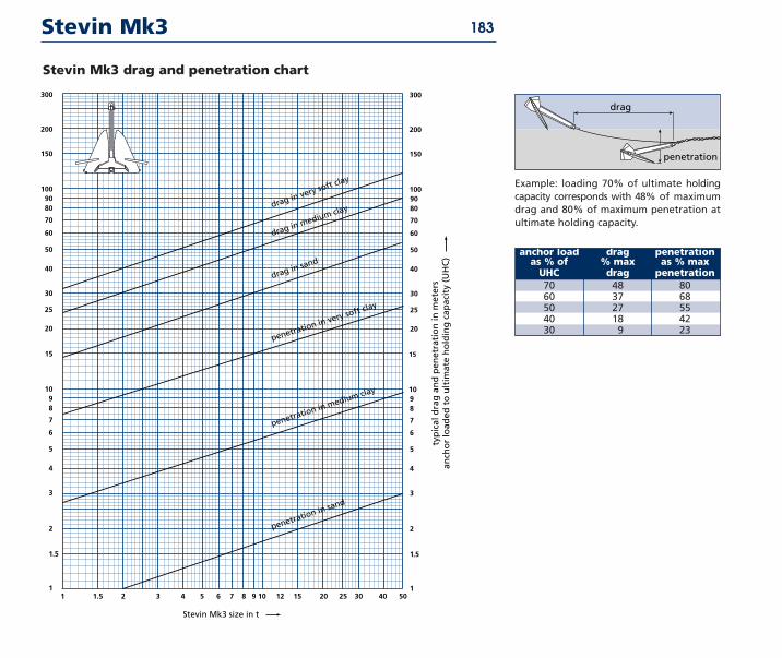
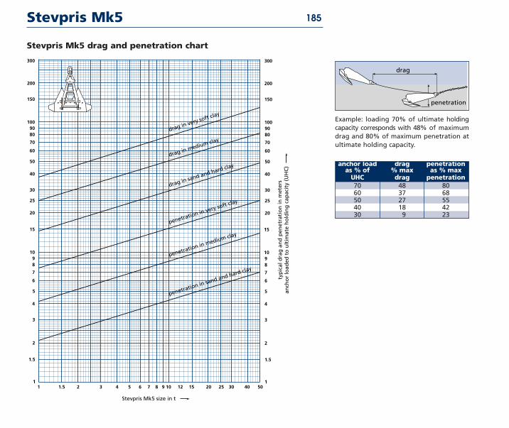
bull Drag and pen e tra tion of the anchor should be record ed dur ing test ing
bull The anchor should be held under ten sion with a blocked winch for 15
min utes to inves ti gate any drop in hold ing capac ity
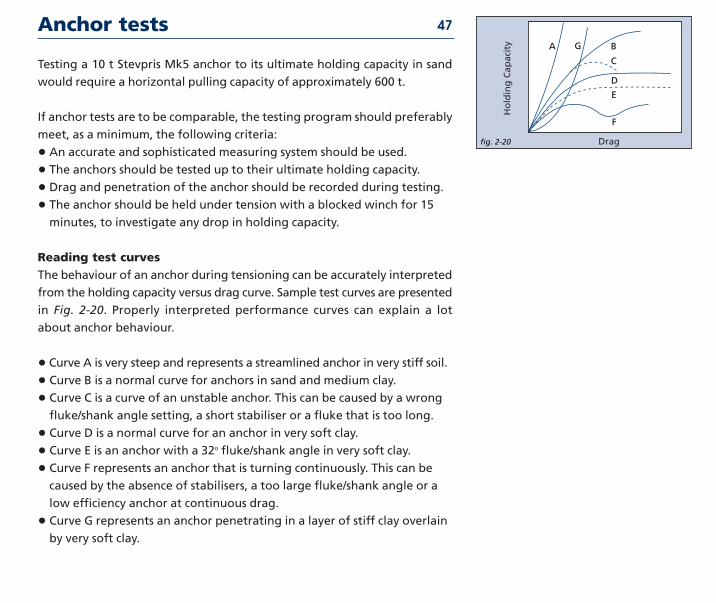
Reading test curvesThe beha vi our of an anchor dur ing ten sion ing can be accu rate ly inter pret ed
from the hold ing capac ity ver sus drag curve Sample test curves are pre sent ed
in Fig 2-20 Properly inter pret ed per for mance curves can explain a lot
about anchor beha vi our
bull Curve A is very steep and rep re sents a stream lined anchor in very stiff soil
bull Curve B is a nor mal curve for anchors in sand and medi um clay
bull Curve C is a curve of an unstable anchor This can be caused by a wrong
flukeshank angle set ting a short stab i lis er or a fluke that is too long
bull Curve D is a nor mal curve for an anchor in very soft clay
bull Curve E is an anchor with a 32o flukeshank angle in very soft clay
bull Curve F rep re sents an anchor that is turn ing con tin u ous ly This can be
caused by the absence of stab il is ers a too large flukeshank angle or a
low effi cien cy anchor at con tin u ous drag
bull Curve G rep re sents an anchor pen e trat ing in a layer of stiff clay over lain
by very soft clay
Anchor tests
Curves A B D E and G show a very stable ris ing line which indi cates that
the anchor builds up its hold ing capac ity con stant ly until the ulti mate hold ing
capac ity has been reached after which the anchor shows con tin u ous drag
The other curves are large ly self-explan a to ry
Test resultsVryhofrsquos exten sive data base of test results with dif fer ent anchor types sizes
and soil con di tions has been fre quent ly used in anchor design Data has
been obtained from prac tice scale mod els and from third par ties The data
has been inter pret ed and after wards incor po rat ed in the ulti mate hold ing
capac ity drag and pen e tra tion graphs of the Stevin Mk3 and Stevpris Mk5
anchor as well as in the ulti mate pull-out capac ity graph of the Stevmanta VLA
Norwegian Contractors (1984)In 1984 Norwegian Contractors car ried out tests at Digernessundet Stord
Norway The pur pose of these tests was to deter mine the cor rect anchor type
and size for the moor ing system of the Gullfaks A plat form dur ing the con struc -
tion of the plat form at Digernessundet Although the con struc tion would took
place at one loca tion it was known that three dif fer ent types of soil con di tions
would be encoun tered sand soft mud and an 8 m mud layer on rock After the
initial trials the Stevpris anchor was select ed for fur ther test ing
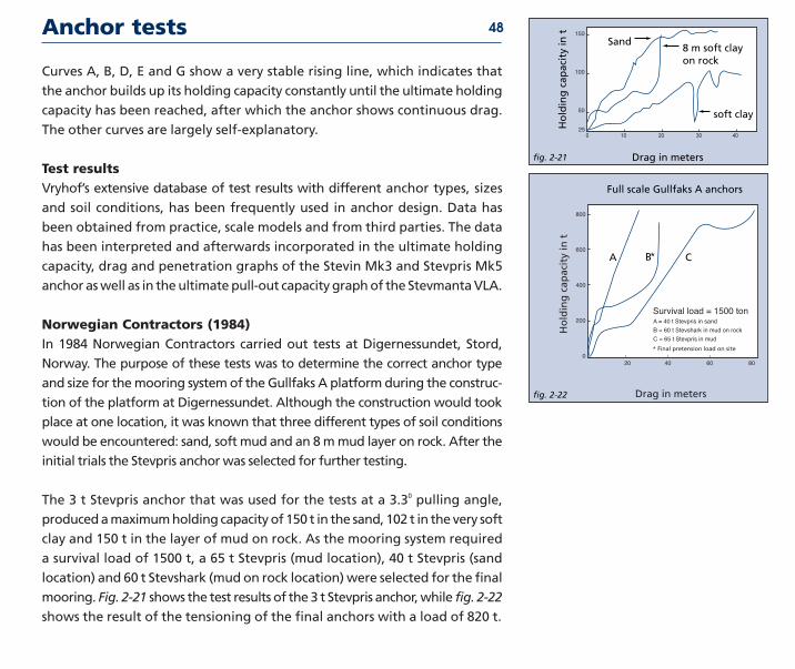
The 3 t Stevpris anchor that was used for the tests at a 330 pull ing angle
pro duced a max i mum hold ing capac ity of 150 t in the sand 102 t in the very soft
clay and 150 t in the layer of mud on rock As the moor ing system required
a sur vi val load of 1500 t a 65 t Stevpris (mud loca tion) 40 t Stevpris (sand
loca tion) and 60 t Stevshark (mud on rock loca tion) were select ed for the final
moor ing Fig 2-21 shows the test results of the 3 t Stevpris anchor while fig 2-22
shows the result of the ten sion ing of the final anchors with a load of 820 t
48
fig 2-21
150
100
50
250 10 20 30 40
Sand8 m soft clay 13on rock1313
Ho
ldin
g c
apac
ity
in t
soft clay1313
Drag in meters
fig 2-22
800
700
600
500
400
300
200
100
0
20 40 60 80
Full scale Gullfaks A anchors
Ho
ldin
g c
apac
ity
in t
Drag in meters
A B C
A = 40 t Stevpris in sand
B = 60 t Stevshark in mud on rock
C = 65 t Stevpris in mud
Survival load = 1500 ton
Final pretension load on site
Anchor tests 49
fig 2-23
700
600
500
400
300
200
100
0 50 100 150 200 250 300 350 400 450 500
Drag distance in feet
7-2
7-3
7-47-1
2-2
2-1
Large scale anchor test jip - 7 amp 2 t
Ho
rizo
nta
l lo
ad in
kip
s
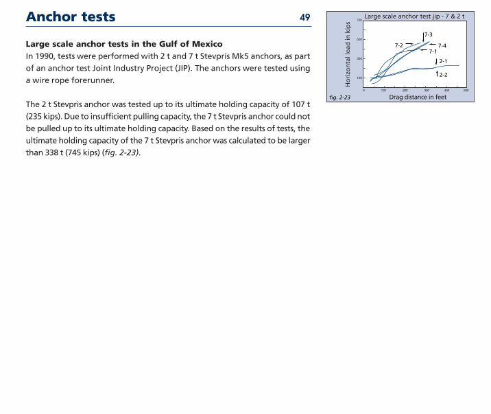
Large scale anchor tests in the Gulf of MexicoIn 1990 tests were per formed with 2 t and 7 t Stevpris Mk5 anchors as part
of an anchor test Joint Industry Project (JIP) The anchors were test ed using
a wire rope fore run ner
The 2 t Stevpris anchor was test ed up to its ulti mate hold ing capac ity of 107 t
(235 kips) Due to insuf fi cient pull ing capac ity the 7 t Stevpris anchor could not
be pulled up to its ulti mate hold ing capac ity Based on the results of tests the
ulti mate hold ing capac ity of the 7 t Stevpris anchor was cal cu lat ed to be larg er
than 338 t (745 kips) (fig 2-23)
Anchor tests
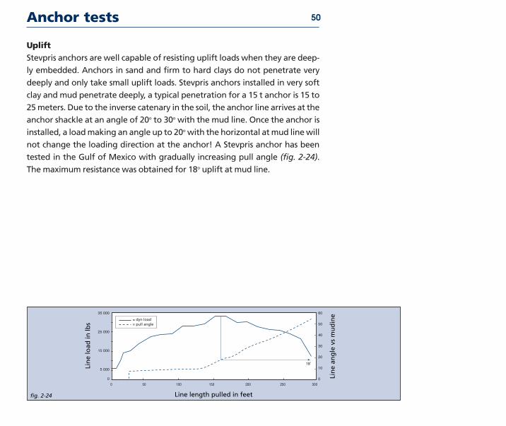
UpliftStevpris anchors are well capable of resist ing uplift loads when they are deep -
ly embed ded Anchors in sand and firm to hard clays do not pen e trate very
deeply and only take small uplift loads Stevpris anchors installed in very soft
clay and mud pen e trate deeply a typ i cal pen e tra tion for a 15 t anchor is 15 to
25 meters Due to the inverse cat en ary in the soil the anchor line arrives at the
anchor shack le at an angle of 20o to 30o with the mud line Once the anchor is
installed a load mak ing an angle up to 20o with the hor i zon tal at mud line will
not change the load ing direc tion at the anchor A Stevpris anchor has been
test ed in the Gulf of Mexico with grad u al ly increas ing pull angle (fig 2-24)
The max i mum resis tance was obtained for 18o uplift at mud line
50
fig 2-24
13
35 000
30 000
25 000
20 000
15 000
10 000
5 000
0
60
50
40
30
20
10
0
0 50 100 150 200 250 300
= dyn load13= pull angle
Lin
e an
gle
vs
mu
din
e
Line length pulled in feet
Lin
e lo
ad in
lbs
18˚13
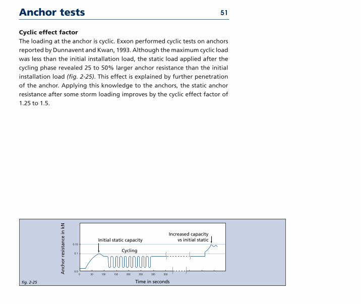
Cyclic effect fac torThe load ing at the anchor is cyclic Exxon per formed cyclic tests on anchors
report ed by Dunnavent and Kwan 1993 Although the max i mum cyclic load
was less than the initial instal la tion load the stat ic load applied after the
cycling phase revealed 25 to 50 larg er anchor resis tance than the initial
instal la tion load (fig 2-25) This effect is explained by fur ther pen e tra tion
of the anchor Applying this knowl edge to the anchors the stat ic anchor
resis tance after some storm load ing improves by the cyclic effect fac tor of
125 to 15
Anchor tests 51
fig 2-25
015
01
000 50 100 150 200 250 300 350
Time in seconds
An
cho
r re
sist
ance
in k
N
Initial static capacity
Cycling
Increased capacity13vs initial static
Anchor tests 52
fig 2-26
200
150
100
50
0
0 5 10 15 20 25 30 35
13
Line length pulled in feet
Block winch
13Change mode13
13
Lin
e lo
ad in
13900 pulling 13angle with 13seabed in 13normal 13loading 13mode
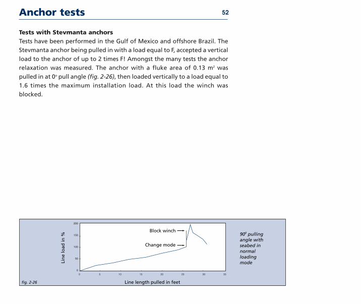
Tests with Stevmanta anchorsTests have been per formed in the Gulf of Mexico and offshore Brazil The
Stevmanta anchor being pulled in with a load equal to F accept ed a ver ti cal
load to the anchor of up to 2 times F Amongst the many tests the anchor
relax a tion was meas ured The anchor with a fluke area of 013 m2 was
pulled in at 0o pull angle (fig 2-26) then load ed ver ti cal ly to a load equal to
16 times the max i mum instal la tion load At this load the winch was
blocked
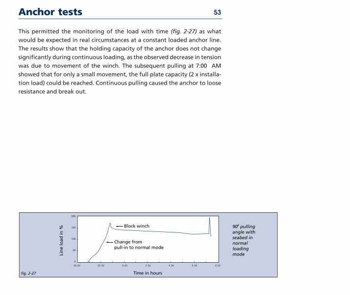
Anchor tests 53
fig 2-27
200
150
100
50
0
2000 2200 0 00 2 00 4 00 6 00 8 00
Time in hours
Lin
e lo
ad in
13Change from 13pull-in to normal mode 1313
13Block winch 1313
13900 pulling 13angle with 13seabed in 13normal 13loading 13mode
This per mit ted the mon i tor ing of the load with time (fig 2-27) as what
would be expect ed in real cir cum stanc es at a con stant load ed anchor line
The results show that the hold ing capac ity of the anchor does not change
sig nif i cant ly dur ing con tin u ous load ing as the observed decrease in ten sion
was due to move ment of the winch The sub se quent pull ing at 700 AM
showed that for only a small move ment the full plate capac ity (2 x instal la -
tion load) could be reached Continuous pull ing caused the anchor to loose
resis tance and break out
Anchor tests
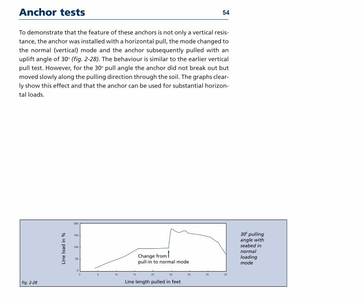
To dem on strate that the fea ture of these anchors is not only a ver ti cal resis -
tance the anchor was installed with a hor i zon tal pull the mode changed to
the nor mal (ver ti cal) mode and the anchor sub se quent ly pulled with an
uplift angle of 30o (fig 2-28) The beha vi our is sim i lar to the ear li er ver ti cal
pull test However for the 30o pull angle the anchor did not break out but
moved slow ly along the pull ing direc tion through the soil The graphs clear -
ly show this effect and that the anchor can be used for sub stan tial hor i zon -
tal loads
54
fig 2-28
13
200
150
100
50
0
0 5 10 15 20 25 30 35 40
Line length pulled in feet
13Change from 13pull-in to normal mode 1313
Lin
e lo
ad in
13300 pulling 13angle with 13seabed in 13normal 13loading 13mode
Soil table
Increasing lithification
Increasing grain size of
particulate deposits
000
2 mm
006
3 mm
2 mm
60 m
m
Carbonate silt
Carbonate sand
Carbonate grave
l
Carbonate clay
Silic
eous ca
rbonate
Silic
eous ca
rbonate
silt
sand
Mixed
carbo
nate and
non-carbonate gravel
Calca
reous clay
Calca
reous silic
a silt
Calca
reous silic
a sand
Clay
Silic
a silt
Silic
a sand
Silic
a grave
l
Calcilutite
Calcisiltite (carb
Calca
renite (carb
Calciru
dite (carb
(carb Calysto
ne)
Siltstone)
Sandstone)
Conglom Or Breccia
Conglomeratic
Claye
y ca
lcilu
tute
Silic
eous ca
lcisiltite
Silic
eous ca
lcaren
ite
calcirudite
Calca
reous
Calcareao
us clay
stone
Calca
reous siltstone
Calca
reous sandstone
conglomerate
Conglomerate or
Claysto
ne
Siltstone
Sandstone
breccia
Fine-grained
lim
esto
ne
Detrital lim
esto
ne
Conglomerat
limesto
ne
Fine-grained
Fine-grained
silice
ous
Silic
eous detrital
Conglomerate
agrilla
ceous lim
estone
limesto
ne
limesto
ne
limesto
ne
Calca
reous
Calcareous clay
stone
Calca
reous siltstone
Calca
reous sandstone
conglomerate
Conglomerate of
Claysto
ne
Siltstone
Sandstone
Breccia
Crystallin
e lim
esto
ne or marble
Conve
ntional m
etam
orp
hic nomen
clature applie
s in this sec
tion
Approx Rock Very weak Weak to moderately weak Moderately strong to strong Strong to extemelystrength strong
Cementation of Very weak to firmly Well cemented soil (well cemented)soil cemented soil rock
Total carbonate content
90 50 10 90 50 10 90 50 10 50
55
Practice
3
PracticeAlthough theoretical knowledge of anchors is essential for good anchor design
and selection the practical issues are just as important The handling of an
anchor and the selection and use of support equipment is of equal importance
Anchor handling is a critically important and often complicated process It is
influenced by such factors as the weight and shape of the anchor the nature
of the soil the depth of the water the weather conditions the available
handling equipment and the type and weight of mooring line It is for these
reasons that anchor handling is a subject which requires careful considera-
tion Without proper anchor handling optimal performance of an anchor is
not possible
In the process of handling anchors various types of support equipment are
necessary or beneficial An anchor manual would be incomplete without
consideration of these auxiliary items the reasons for their use their oper-
ation and the advantages and drawbacks involved
This chapter gives an overview of the recommended procedures that should
be followed for anchor handling and the types and use of the support
equipment during the handling operations The following handling
procedures are by no means complete but they do give some suggestions
which can be applied to each anchor handling procedure and adapted for
specific circumstances and locations
Some of the topics covered in this chapter are
requirements for a soil survey connection of the anchor to the mooring
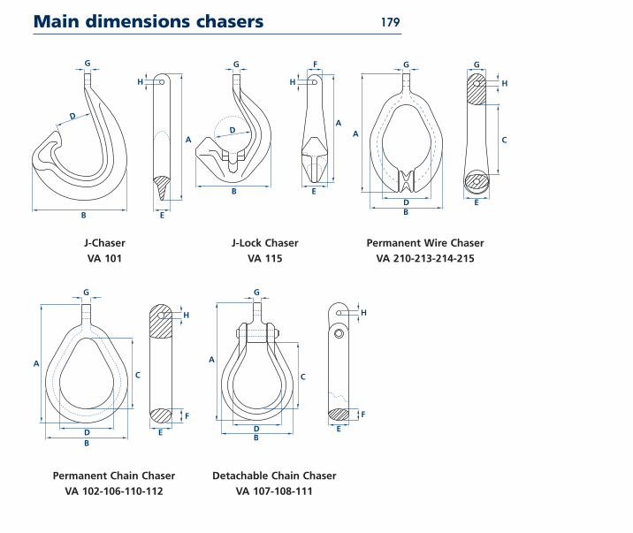
line chasers handling the Stevpris anchor handling the Stevmanta anchor
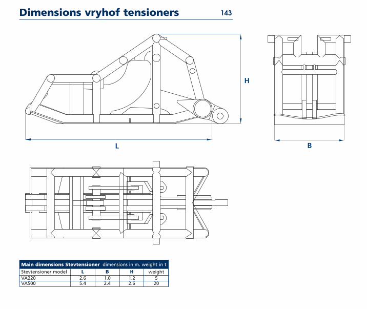
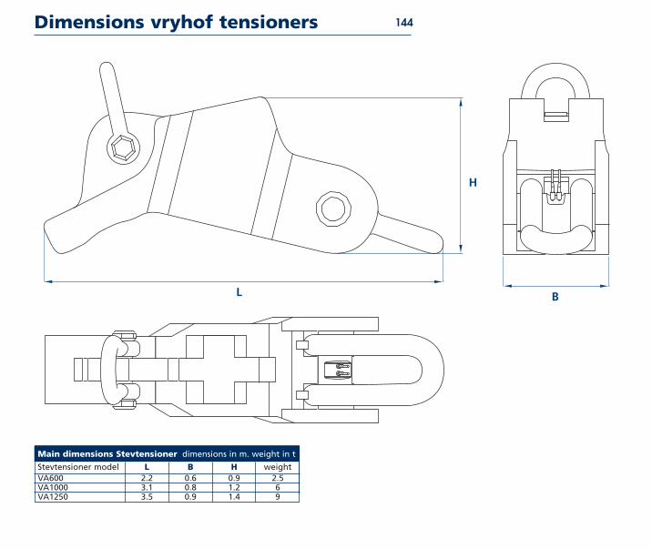
the Stevtensioner anchor handlingsupply vessels
Introduction 57
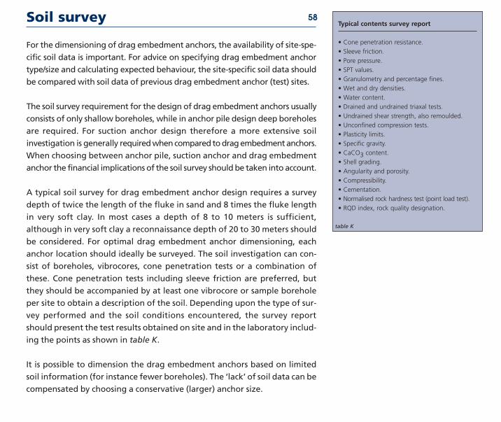
Soil survey 58Typical contents survey report
bull Cone pen e tra tion resis tance
bull Sleeve fric tion
bull Pore pres sure
bull SPT val ues
bull Gra nu lom e try and per cent age fines
bull Wet and dry den sities
bull Water con tent
bull Drained and undrained tri ax al tests
bull Undrained shear strength also remould ed
bull Uncon fined com pres sion tests
bull Plas tic ity lim its
bull Spe cif ic grav ity
bull CaCO3 con tent
bull Shell grad ing
bull Angu lar ity and poros ity
bull Com press ibil ity
bull Cemen ta tion
bull Nor mal ised rock hard ness test (point load test)
bull RQD index rock qual ity des ig na tion
table K
For the dimen sion ing of drag embed ment anchors the avail abil ity of site-spe -
cif ic soil data is impor tant For advice on spec i fy ing drag embed ment anchor
typesize and cal cu lat ing expect ed beha vi our the site-spe cif ic soil data should
be com pared with soil data of pre vi ous drag embed ment anchor (test) sites
The soil sur vey require ment for the design of drag embed ment anchors usu al ly
con sists of only shal low bore holes while in anchor pile design deep bore holes
are required For suc tion anchor design therefore a more exten sive soil
inves ti ga tion is generally required when com pared to drag embed ment anchors
When choos ing between anchor pile suc tion anchor and drag embed ment
anchor the finan cial impli ca tions of the soil sur vey should be taken into account
A typ i cal soil sur vey for drag embed ment anchor design requires a sur vey
depth of twice the length of the fluke in sand and 8 times the fluke length
in very soft clay In most cases a depth of 8 to 10 meters is suf fi cient
although in very soft clay a recon nais sance depth of 20 to 30 meters should
be con sid ered For opti mal drag embed ment anchor dimen sion ing each
anchor loca tion should ideal ly be sur veyed The soil inves ti ga tion can con -
sist of bore holes vib ro cores cone pen e tra tion tests or a com bi na tion of
these Cone pen e tra tion tests includ ing sleeve fric tion are pre ferred but
they should be accom pa nied by at least one vib ro core or sam ple bore hole
per site to obtain a descrip tion of the soil Depending upon the type of sur -
vey per formed and the soil con di tions encoun tered the sur vey report
should present the test results obtained on site and in the labor a to ry includ -
ing the points as shown in table K
It is pos sible to dimen sion the drag embed ment anchors based on lim it ed
soil infor ma tion (for instance fewer bore holes) The lsquolackrsquo of soil data can be
com pen sat ed by choos ing a con ser va tive (larger) anchor size
Pile or anchor 59
The choice between piles and anchors is only pos sible for per ma nent
systems Piles are not a good invest ment when an anchored entity must be
moved But the choice is often made for piles on emo tion al grounds a pile
does not drag However anchors that are prop er ly pre-ten sioned on site
will also not drag
While it is a psy cho log i cal ly load ed sub ject expe ri ence has shown that the
choice between anchor and pile is mere ly a mat ter of eco nom ics The
required pile weight for a system is equal to the required weight of a
Stevpris anchor Piles cost about 40 of equiv a lent capa bil ity anchors
However the instal la tion costs for piles are much high er Piles require a fol -
low er and a pile ham mer The instal la tion spread for piles is much more sig -
nif i cant a crane barge with sup port spread ver sus the two anchor han dling
ves sels The weath er downtime for a spread involv ing a crane ves sel is much
long er than when AHVs are used To allow drag of the anchors dur ing pre -
ten sion ing extra chain length is required Sometimes the pre ten sion load
for piles is much less than for anchors The sur vey work for anchors is gen er -
al ly much sim pler than for piles When aban don ing a field anchor remov al
is much cheap er than remov al of installed piles The choice between piles
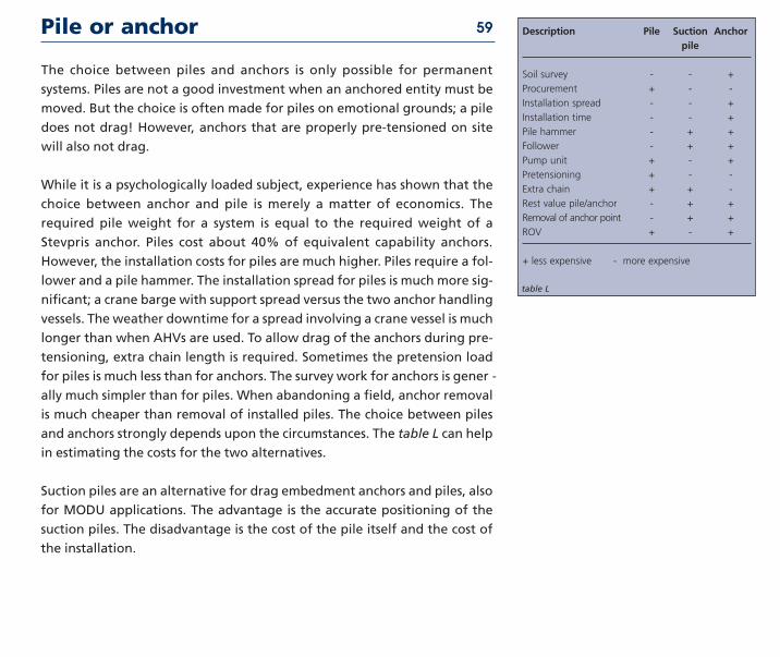
and anchors strong ly depends upon the cir cum stanc es The table L can help
in esti mat ing the costs for the two alter na tives
Suction piles are an alternative for drag embedment anchors and piles also
for MODU applications The advantage is the accurate positioning of the
suction piles The disadvantage is the cost of the pile itself and the cost of
the installation
Description Pile Suction Anchorpile
Soil survey - - +
Procurement + - -
Installation spread - - +
Installation time - - +
Pile hammer - + +
Follower - + +
Pump unit + - +
Pretensioning + - -
Extra chain + + -
Rest value pileanchor - + +
Removal of anchor point - + +
ROV + - +
+ less expensive - more expensive
table L
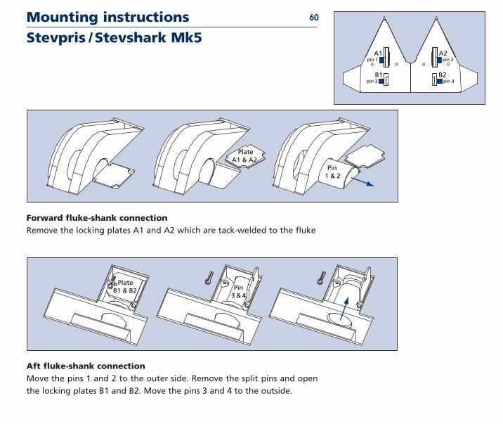
Mounting instructions Stevpris Stevshark Mk5
A1pin 1 pin 2
pin 3 pin 4B1 B2
A2
13
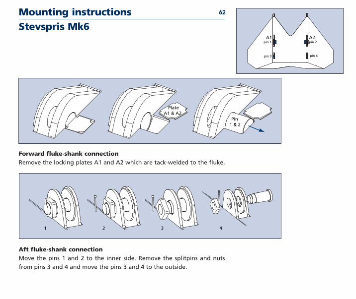
Forward fluke-shank connectionRemove the locking plates A1 and A2 which are tack-welded to the fluke
Aft fluke-shank connectionMove the pins 1 and 2 to the outer side Remove the split pins and open
the locking plates B1 and B2 Move the pins 3 and 4 to the outside
60
Plate A1 amp A2
Pin 1 amp 2
Plate B1 amp B2 Pin
3 amp 4
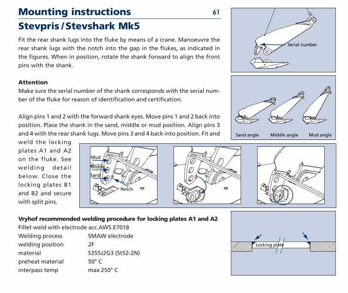
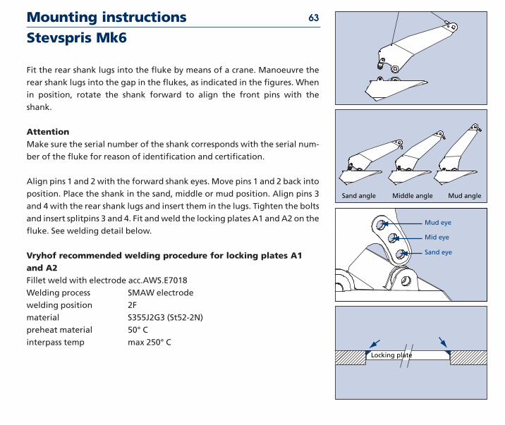
Fit the rear shank lugs into the fluke by means of a crane Manoeuvre the
rear shank lugs with the notch into the gap in the flukes as indicated in
the figures When in position rotate the shank forward to align the front
pins with the shank
AttentionMake sure the serial number of the shank corresponds with the serial num-
ber of the fluke for reason of identification and certification
Align pins 1 and 2 with the forward shank eyes Move pins 1 and 2 back into
position Place the shank in the sand middle or mud position Align pins 3
and 4 with the rear shank lugs Move pins 3 and 4 back into position Fit and
weld the locking
plates A1 and A2
on the fluke See
welding detai l
below Close the
locking plates B1
and B2 and secure
with split pins
Vryhof recommended welding procedure for locking plates A1 and A2Fillet weld with electrode accAWSE7018
Welding process SMAW electrode
welding position 2F
material S355J2G3 (St52-2N)
preheat material 50deg C
interpass temp max 250deg C
Mounting instructions Stevpris Stevshark Mk5
13
Serial number
Sand angle Middle angle Mud angle
Locking plate
61
Mud
Middle
Sand
Notch
Mounting instructions Stevspris Mk6
13
A1pin 1 pin 2
pin 3 pin 4
A2
13
Plate A1 amp A2
Pin 1 amp 2
Forward fluke-shank connectionRemove the locking plates A1 and A2 which are tack-welded to the fluke
Aft fluke-shank connectionMove the pins 1 and 2 to the inner side Remove the splitpins and nuts
from pins 3 and 4 and move the pins 3 and 4 to the outside
62
1 2 3 4
Fit the rear shank lugs into the fluke by means of a crane Manoeuvre the
rear shank lugs into the gap in the flukes as indicated in the figures When
in position rotate the shank forward to align the front pins with the
shank
AttentionMake sure the serial number of the shank corresponds with the serial num-
ber of the fluke for reason of identification and certification
Align pins 1 and 2 with the forward shank eyes Move pins 1 and 2 back into
position Place the shank in the sand middle or mud position Align pins 3
and 4 with the rear shank lugs and insert them in the lugs Tighten the bolts
and insert splitpins 3 and 4 Fit and weld the locking plates A1 and A2 on the
fluke See welding detail below
Vryhof recommended welding procedure for locking plates A1and A2Fillet weld with electrode accAWSE7018
Welding process SMAW electrode
welding position 2F
material S355J2G3 (St52-2N)
preheat material 50deg C
interpass temp max 250deg C
Mounting instructions Stevspris Mk6
13
Sand angle Middle angle Mud angle
Mud eye
13
Mid eye
Sand eye
Locking plate
63
Setting the flukeshank angle
Introduction
In soil such as sand and medium to hard clay an anchor with a flukeshank
angle of 32o will give the highest holding power An anchor with a 50o
flukeshank angle in this soil will not penetrate but will drag along the
seabed If used in mud a 50o flukeshank angle is appropriate An anchor with
a 32 o flukeshank angle will penetrate less and generate lower holding
capacity in mud(fig 3-01)
The Stevpris Mk5 anchor has an additional flukeshank angle setting of 41o
which can be adopted in certain layered soil conditions (table M)
Changing the flukeshank angle on the Stevpris Mk3
This can be carried out within half an hour with the Stevpris anchor upside
down on deck
Secure the anchor on deck Connect a tugger wire (C) to the holes (D) on the
bottom side of the fluke Change from mud to sand angle by removing the
locking plates and the two rear pins in (B) decrease the flukeshank angle
by hauling the cable (C) Reinstall the pins and locking plates in (A) Seal
weld the lock-ing plates do not weld them to the pins (fig 3-02)
64
fig 3-01
no penetration
D
fluke angle too large in hard soil
change from mud to sand angle
fig 3-02
Soil type Optimalflukeshankangle setting
Very soft clay (mud) 500
Certain layered soils 410
Medium to hard clay
or sand 320
Stevpris Mk5 only
table M
Setting the flukeshank angle 65
Change from sand to the mud position increase angle by veering (C) change
over pin and locking plates from (A) to (B) No special welding requirements
(fig 3-03)
Changing the flukeshank angle on the Stevpris Mk5 Changing the
flukeshank angle on the Stevpris Mk5 anchor is even quicker No welding
required Veering and hauling (C) to change the flukeshank angle as
above the pin however remains in (A) the locking plate is secured by means
of a cotter pin (fig 3-04)
change from sand to mud angle
fig 3-03
change flukeshank angle Stevpris Mk5
fig 3-04
Connecting a swivel to the Stevpris anchorTo connect a swivel to the Stevpris anchor several different configurations
are possible These are
Type I - The swivel is connected directly to the shank of the anchor thus
omitting the anchor shackle (fig 3-05)
J swivel shackle C end link B enlarged link A common link
Type II - The swivel is connected to the anchor shackle (fig 3-06)
J swivel shackle C end link B enlarged link A common link
Type III - The swivel is connected to the anchor shackle via a special design
end link
(fig 3-07)
K special end link J swivel C end link B enlarged link A com-
mon link
Type IV - The swivel is part of a forerunner connected to the anchor shack-
le for instance the forerunners VA02 VA04 and VA 06 described
in the product data section (fig 3-08)
PL pear link A common link B enlarged link H swivel
When a chaser is used in combination with the Stevpris and swivel some of
the configurations mentioned above are more suitable than others In gen-
eral swivels are only designed to withstand longitudinal forces and are
usually not designed for use in combination with chasers The design of the
chaser tends to stop it at the swivel Consequently there will be high
bending forces on the swivel which can result in damage or even breakage
Connecting a swivel 66
J C B A
fig 3-05
fig 3-06
J C B A
fig 3-07
K J C B A
fig 3-08
P L A B H B A
Generally it is best when the swivel is fitted some distance from the anchor
when a chaser is used The chaser can then pass the swivel and stop on the
anchor shank When a load is applied to the chaser the swivel is only loaded
longitudinally This means that in combination with the use of a chaser the
configuration type III and type IV are preferred
When the swivel (or swivel forerunner) is connected to the anchor shackle
by means of an end shackle and a chaser is used the end shackle and the
anchor shackle should be connected bow through bow instead of pin
through bow as is normal practice This to minimise the chance of damage
to the shackles
The illustrations fig 3-09 through fig 3-14 show how and how not to
connect the swivel to the Stevpris anchor when using a chaser
(See next page for fig 3-13 and 3-14)
Connecting a swivel 67 damage possible
fig 3-09
NO
fig 3-10
damage possible
fig 3-11
fig 3-12
NO
Connecting a swivel
The best method for chasing with a swivel in the system is to maintain the
tension of the anchor line as much as possible during chasing This will make
the chaser pass more easily over the swivel
68 damage possible
fig 3-13
fig 3-14
NO
Chasers 69
Chasers and their applicationTo facilitate handling pendant wires may be applied to retrieve the anchor
These wires are connected to a pendant eye situated on the anchor and
equipped with a buoy for picking up In deeper water higher anchor
break-out forces are encountered resulting in longer heavier pendant
wires and consequently larger buoys Due to wear caused by the continuous
movement of the buoy by the waves these pendants will break close to the
buoy The buoys would then float free and the anchors are much more
difficult to recover
To overcome this chasers were introduced These were rings lsquochasedrsquo along
the cable towards the anchor and back again to a rig or handling vessel
Their function was to ensure both installation and break-out of the anchor
without having to use a pendant linebuoy The chaser system thus totally
eliminates buoys partly eliminates cables and reduces wear on the system
The cost of a chaser is small when compared to the cost of a mooring line It
is therefore extremely important from an operatorrsquos viewpoint that chasers
do not inflict damage to the mooring lines
Chasers 70
Towing a chaser along mooring lines with at times high interface
pressures must result in wear It is thus essential that such wear is taken by
the chaser and not the mooring line The chasers vryhof recommends are
manufactured in a material that is softer than the steel used for the
mooring line Chaser wear is induced by the application of high interface
pressure between the mooring line and the chaser High interface pressure
can arise from
bull Pulling the chaser along a slack mooring line
bull Maintaining high tension in the chaser workwire when chasing a
tensioned mooring line
Chasing operations are best carried out on mooring lines which are fully
tensioned There is little need for the application of high interface pressure
while chasing the permanent chaser is captive on the mooring line and
unlike the J-chaser will not become disengaged due to a slack work wire
For optimum chasing operations the length of the chaser pendant line
should be at least 15 times the waterdepth
There are many different types of chaser available on the market today
A selection of the different chaser types is described in more detail on the
following pages
Chaser types 71
fig 3-16
fig 3-15
The J-chaserThe J-chaser (fig 3-15) is used on mooring lines where the anchor has to be
recovered and no permanent chaser has been installed or the normal
recovery mechanism has failed In other cases the J-chaser is used simply to
keep a chain free from a pipeline during deployment of the anchors The
chaser is deployed over the stern roller of an AHV at approximately 13 of
the water depth The chaser is towed across the mooring catenary until it
catches the chain It is then towed into contact with the anchor shankfluke
for anchor break-out and retrieval
The permanent chain chaserAs a practical alternative to the buoy and pendant the permanent chain
chaser (fig 3-16) was introduced Originally simple shackles were used
these were followed by special cast oval rings which were attached to a pen-
dant by a lsquobightrsquo of chain and shackle Very soon afterwards the pear-shaped
chaser with shackle eye was introduced The design of these chasers offers
superior sliding and penetration properties
Chaser types 72
fig 3-18
The detachable chain chaserFor rigs in service it is sometimes preferred to equip the mooring with a
chaser which does not require the anchor chain to be broken and re-made
Detachable chain chasers (fig 3-17) were introduced to satisfy this need
The withdrawal and replacement of the single bolt permits easy assembly of
the chaser on the mooring cable
The permanent wire chaserThe permanent wire chaser (fig 3-18) was introduced when rigs moved to
deeper waters and composite wirechain mooring systems became neces-
sary The chaser incorporates a lsquorockerrsquo which is centrally mounted on a
hinge bolt The rocker has two opposing grooves and when the chaser is
engaged with the mooring line the wire slides through one of these
grooves irrespective of the angle which the chaser makes with the mooring
The large radius at the base of the groove assists in reducing wear of the
rocker and avoids severe lsquoopeningrsquo of the lay of the wire if a loop of wire is
pulled during the handling process The material of the rocker is not as hard
as the material of the wire This means that wear is taken by the rocker
without damage to the wire and because the rocker is easily removable
replacement is relatively inexpensive The permanent wire chaser is easily
detachable by removal and re-assembly of the hinge bolt and rocker
Some designs of wire chaser incorporate fully rotating rollers over which
the mooring wire passes To be effective such rollers need to be of a large
diameter and require to be supported by bearings They are consequently
larger heavier and much more costly than the permanent wire chasers dis-
cussed above and because of their size they require more power at the
AHV to penetrate the seabed and reach the anchor
fig 3-17
Chaser types 73
fig 3-19
The J-lock chaserThe J-lock chaser (fig 3-19) has been designed so that it can slide along the
chain in one direction and when the pulling direction is reversed the chas-
er locks on the chain and does not slide any further This means that the
tension in the mooring line can be wholly transferred from the rig to the
chaser The J-shape permits catching the anchor chain after the anchor has
been installed This means that this chaser can be used to assist in unforeseen
circumstances The well-balanced and lsquoguidingrsquo design of the chaser enables
catching the chain when the chaser approaches a mooring at a point where
the catenary angle is as high as 450
When a normal permanent chaser is used under unforeseen conditions
there is the chance that the AHV cannot break out the anchor by means of
the chaser The J-lock chaser can help in such an instance It is released from
a second AHV and slides along the chain towards the anchor The design
prevents the J-lock chaser from sliding back The J-lock chaser is stopped at
the permanent chaser If the winch pull of both tugs is now increased the
J-lock chaser prevents the permanent chaser from sliding away from the
anchor Consequently the forces required do not increase and the anchor
can easily be broken out After this operation the J-lock chaser can be released
again
This chaser can also be used when a very heavy chain has to be installed It
assists during installation by lifting the chain
Stevpris installation 74
fig 3-20
chaser
fig 3-21
always deck anchor with chain between flukes
D
fig 3-22
quickly pass drum
D
fig 3-23
triangular plates on drum
D
Stevpris deployment for MODUs
IntroductionTypical methods for deployment and retrieval of Stevpris anchors with an
anchor handling vessel (AHV) are described focusing on the use of chasers
for handling the anchor (fig 3-20) This is the most common practice on
mobile drilling rigs (MODUs) Handling using permanent pendant lines is
similar
Deployment procedures for the Stevpris anchor will also be given for
permanent moorings where chasers are normally not used
Laying anchorsIt is preferred and by some operators required to deck the anchor before
run out to check the jewellery Run the anchor line out the full distance with
anchor on deck or on roller with the chain between the flukes (fig 3-21)
Boat increases power until anchor line tension rises on rig winch tension
meter When rig gives order to lower the anchor veer pendant till anchor
arrives at roller Allow the anchor some speed to negotiate the bump at the
change-over from the deck on to the roller (fig 3-22)
If anchor is kept on roller keep triangular plates below the main shackle on
the drum for stability of the anchor Alternatively the chaser can be kept on
deckroller In this situation the propeller thrust passes underneath the
anchor and does not influence the fluke (fig 3-23)
Stevpris installation 75
fig 3-24
STOP
fig 3-25
fig 3-26
wait for signal rig
D
Reduce propulsion momentarily when anchor passes the propeller thrust
keep chaser on anchor head for control of anchor orientation and lower
anchor (fig 3-24)
Once below the propeller wash zone reactivate and maintain propeller
thrust to well above 30 tons Keep constant tension in order to ensure
anchor does not fall through chaser ie anchor remains in the chaser and
orientation of the anchor is correct (fig 3-25)
Note In some circumstances AHVs prefer to run the anchor hanging from
the pendant line below the propeller wash approximately 60 to 80 meter
above the seabed This method requires less power on the winch during the
actual laying of the anchor If this method is employed make sure that at all
times the anchor is correctly oriented in the chaser Keep constant tension
in the pendant line to prevent the anchor from falling through the chaser and
possibly turn
Stop lowering when anchor hangs 10 to 15 meter above the bottom and
advise rig Rig now instructs AHV to pay out until pendant line is 14 to 15
times the water depth in shallow water (100m) and 13 to 14 times in deep-
er water AHV increases power till tension is again seen to rise at the rig ie
the load in the line is larger than the chain-soil friction (fig 3-26)
Rig commences to pull in slowly AHV further increases power until tension
rises further at rig winch At this moment rig orders AHV to lay the anchor
AHV immediately stops the propulsion and is consequently pulled back-
wards AHV pays out pendant and maintains paying out pendant after anchor
has landed on the bottom till a wire length of 15 to 2 times the water depth
is out Enough slack wire must be paid out not to disturb the anchor during
buoying off or waiting Stay above or behind the anchor
Stevpris installation 76
fig 3-30
patience in very soft soils
D
fig 3-27
rig hauls AHV slacks
D
fig 3-28
do not pull after landing
D
fig 3-29
wrong keep cable 13under tension
D
Rig continues heaving the cable to a sufficient load equal to the total
chainsoil friction plus 50 t to embed the anchor fully and create confidence
in good setting
This also gives stability to the anchor when the AHV strips the chaser back
or buoys off the pendant Now the AHV can retrieve the chaser and return
to the rig If circumstances allow the rig can tension up to the full preten-
sion load directly (fig 3-27)
No extra pull after landing
It is customary with older anchors such as Danforth Moorfast etc to give
another pull once the anchor is on bottom Do not do this with Stevpris
anchors Once the anchor hits bottom AHV should not pull again Pendant
line must remain slack otherwise anchor could land upside down
(fig 3-28) Suggestion pre-load the anchors to the maximum required
pretension load as soon as the chaser is 100 meter or more ahead of the
anchor ie do not wait If anchor has not been laid correctly a rerun can be
made immediately
Retrieving anchorsThe chaser should be brought to the anchor with a pendant of at least the
length of 15 to 2 times the water depth measured from the stern roller
Chaser should hang freely down from the anchor line till the bottom is
reached ie slack in the pendant line A too short pendant andor too little
tension in the cable results in a situation as sketched (fig 3-29)
While chasing the rig should maintain tension of 60 to 70 of the pre-load
tension No tension in pendant to ensure smooth passing over the chain
When chaser is pulled into contact with anchor shank increase thrust and
keep thrust while heaving especially in rough water (fig 3-30)
Stevpris installation 77
fig 3-31
keep13pullingrig13
hauls
D
fig 3-32
always deck anchor with chain between flukes
D
fig 3-33
keep tension
D
fig 3-34
wrong anchor cannot deck
D
The motion of the vessel itself now helps gradually to break the anchor
loose Sequentially with the vessels motion the pendant is shortened
gradually Anchors in very soft clay can be buried very deep Have patience
take your time and be gentle with the equipment the anchor will come
The rig can help and speed-up the operation by hauling the anchor line at
the same time Once the anchor is off bottom keep the chaser in contact
with the bow shackle by maintaining sufficient thrust (fig 3-31)
Anchor orientationThe anchor flukes are always oriented towards the rig on deck the anchor
lays on its back with shackle towards AHVs bow and cable between the
upwards directed fluke points Check jewelry (fig 3-32)
It is important to control the anchor orientation at all times for easy racking
laying and decking of the anchor ie keep pendant line under tension
while working the anchor If the anchor slides through the chaser the
anchor has to be pulled back to the stern roller and orientation checked
(fig 3-33)
Decking the Stevpris anchorIf anchor is not correctly oriented reduce propulsion and let anchor slide
down through the chaser Rotation is easier while near the rig where all
loads are lower (fig 3-34)
Stevpris installation 78
fig 3-35 turn
fig 3-36
fig 3-37
stop reduce 13propulsion
D
STOP
Turn the anchor with a shot of propeller wash Then pay out pendant make
sure anchor is below the propeller wash away from the propeller influence
zone (fig 3-35)
Increase propulsion moving AHV forward pulling chaser in contact with the
anchor Make sure the stern roller is perpendicular to the chain the chain
directing between the fluke points (fig 3-36)
With sufficient bollard pull haul pendant stopreduce thrust for only a few
seconds when anchor passes the propeller wash onto the drum Pull anchor
on the drum allow the anchor to turn with its back on the roller fluke
points up Then pull further on deck (fig 3-37)
Stevpris installation 79
With little tension in the line the chain hangs steep against the fluke points
and anchor cannot rotate easily (A) Before rotating the anchor pull on the
cable the anchor will be free to turn (B) and (C) (fig 3-38)
With anchor on the stern roller reactivate propulsion For inspection anchor
can be pulled on deck If required change fluke angle to 32 degrees for
hard soil or to 50 degrees for very soft soil Mind every anchor type will be
unstable and drag in hard soil stiff clay or sand with a fluke angle set for
mud (fig 3-39)
fig 3-38
fig 3-39
Stevpris installation 80
What not to doThe anchor is approaching the drum If the AHV maintains thrust the water
flow will push the fluke (fig 3-40)
If the propeller is not stopped the thrust risks turning the anchor around
the cable then acting as a shaft (fig 3-41)
The relative weight of the anchor increased by the thrust force on the fluke
will cause the anchor and the cable to slide down through the chaser and
control of anchor orientation is lost (fig 3-42)
When the thrust is maintained while hauling in the chaser the cable
prevents the anchor to turn on its back at the stern roller Boarding will be
difficult now The anchor could pass the stern roller on its side and get dam-
aged
So stopreduce the thrust just before the anchor passes the propeller wash
(fig 3-43)
fig 3-40
thrust on anchor makes it swing
fig 3-41
and rotate
fig 3-42
anchor slides through chaser
fig 3-43
damage
Stevpris installation 81
Racking the StevprisRig heaves in anchor line pulling AHV towards it AHV keeps sufficient ten-
sion in pendant chaser remains in tight contact with anchor anchor
remains correctly oriented (fig 3-44)
At some distance from the rig AHV pays out winch wire while keeping suf-
ficient bollard pull (at least 15 times anchor weight) to keep chaser on
anchor head Anchor flukes point towards the rig Rig hauls AHV veers
while keeping some tension in the pendant line transferring the anchor to
the bolster The direction of the anchor cable must now be perpendicular to
the rack (fig 3-45)
When anchor arrives at bolster reduce tension to 15 tons As soon as anchor
is resting on bolsters slack pendant wire completely If tension is not suffi-
cient anchor falls out of control of the chaser and might rotate and make
racking difficult If this occurs bring anchor to the stern of the AHV rotate
anchor with fluke points directing outwards and keep chaser tight on the
anchor (fig 3-46)
Deploying Stevpris from the anchor rack AHV receives pendant from rig and connects to AHV winch wire AHV
moves to a position at a good distance but less than the water depth (for
instance 50 meter dependent on weather) from the rig Stop winch and
keep sufficient tension 20 to 30 tons or more as required to maintain the
chaser on the head of the anchor Only now rig pays out cable while AHV
hauls in on the winch The AHV maintains sufficient tension while pulling
the anchor to the stern roller Reduce the power of the propeller as anchor
passes the wash zone and bring anchor on roller for inspection and reacti-
vate thrust (fig 3-47)
fig 3-44
keep tension
D
fig 3-45
keep tension
D
fig 3-46
wrong 13risk losing control 13over anchor orientation
fig 3-47
keep tension
D
Stevpris installation 82
Boarding the anchor in deep waterIn deep water the weight of the anchor line becomes of predominant
importance For line loads larger than 8 times the anchor weight the anchor
could be pulled against the chaser as illustrated it could even position itself
upside down In such cases boarding the anchor is difficult and damage
might occur (fig 3-48)
The best and preferred solution is to pull the anchor from the bottom and
have the rig haul the anchor line allowing the boarding of the anchor near
the rig where loads are smaller
If this is not possible or allowed for some reason another solution is to
reduce the weight that is hanging from the anchor This can be done by
lifting the anchor line using a lock chaser or grapnel handled by a second
vessel (fig 3-49)
It is recommended to board the anchor with the chain between the fluke
The anchor fluke is generally designed to withstand loads up to 8 times the
anchor weight (fig 3-50)
It happens that the anchor is accidentally pulled over the roller on its side
Due to the large forces damage to shank and fluke might occur when the
chain is hanging over the anchor (fig 3-51)
fig 3-48
anchor weighthigh tension
fig 3-49
lock chaser
fig 3-50
8 x anchor weight
fig 3-51
large weight
Stevpris installation 83
fig 3-52
fig 3-53
with ballast in fluke use chain forerunner
D
chain
wire
If boarding the anchor on its side is inevitable make sure that before
boarding the vessel is turned to free the anchor line from the anchor and
haul gently The chain will pass the stern roller next to the anchor However
this situation should be avoided as damage may occur (fig 3-52)
Ballast in flukeUsing a wire rope forerunner and ballast material placed inside the hollow
fluke the anchor may not topple over with the fluke points directed
downwards A wire anchor line might be too light to position the anchor
correctly and the anchor may not topple over the anchor could skid over
the seabed and prevent penetration
When the fluke is ballasted the weight of a chain forerunner will cause the
shackle to nose down and bring the fluke in penetration position (fig 3-53)
Stevpris installation 84
Chaser equilibriumTo control the anchor the chaser collar must always be on the anchor head
The tension in the anchor cable must be equal or larger than 15 times the
weight of the anchor If not the anchor slides through the chaser and the
orientation is not controlled (fig 3-54)
Equilibrium forces determine if chaser is in contact with the anchor Near
bottom the vertical load at the chaser from the anchor line Flv is small
The chaser remains only in contact with the anchor if the bollard pull Fph is
larger than the horizontal line load Flh which in turn must be larger than
the anchor weight W (if not the anchor will slide down) The angle of the
pendant line must be larger than 45deg (fig 3-55)
Recommendation Bollard pull must always be equal or larger than the line
tension ie use a minimum bollard pull of 20 to 30 tons for a 12 to 15 ton
anchor Use a minimum pendant line length of 14 to 15 times the water
depth in shallow water (100m) and 13 to 14 times the depth in deeper
water (fig 3-56)
fig 3-54
pendant line force
anchor line tension
anchor weight
fig 3-55
Fp
Fph
Fpv
Flh
FlFlv
W
fig 3-56
chaser
Deployment for permanent moorings
The simplest deployment procedure for the Stevpris anchor is to lower the
anchor to the seabed using the mooring line When the anchor is nearly on
the seabed the AHV should start moving slowly forward to ensure that the
anchor lands correctly on the seabed (fig 3-57)
Another option for the deployment of the Stevpris anchor is to connect a
temporary installation bridle (wire rope) to the anchor The bridle is
connected to the padeyes situated at the back of the shank of the anchor
The AHV then lowers the anchor overboard while paying out the mooring
line and the bridle simultaneously (fig 3-58)
To recover a Stevpris anchor after it has been installed the AHV should take
the mooring line and pull it in the opposite direction that the anchor was
installed in generally away from the centre of the mooring The AHV
should recover the mooring line till a length of approximately 15 times the
water depth is still overboard
When only 15 times the water depth of mooring line is left overboard the
AHV should block the winch and keep a constant tension on the mooring
line equal to the pre-load tension Once the anchor starts to move in the
soil a lower tension in the mooring line can be used (fig 3-59)
Stevpris installation 85
fig 3-57
fig 3-58
mooring line
temporary bridle
fig 3-59
Piggy-backing
IntroductionPiggy-back is the practice of using two or more anchors in order to obtain
holding power greater than can be achieved with one only Piggy-backing
is used when anchors are employed with insufficient holding capacity
This can be caused by improper design for the particular environment or
insufficient anchor size
In some soil conditions the use of two smaller anchors in piggy-back can
offer an advantage over the use of one larger anchor This can be the case
when the anchor has to hold in a certain layer and holding capacity in the
underlying layer is uncertain
Considerations to remember on piggy-backing
bullInstalling a piggy-back system is more costly than the installation of a sin-
gle anchor
bullIf the mooring line of the second anchor is connected to the rear of the
first anchor the stability penetration and holding capacity of the first
anchor may be less than is the case for a single anchor The force from the
second anchor may tend to pull the fluke of the first anchor closed (hing-
ing type anchors)
bullIf the piggy-back anchor is connected to the first anchor by means of a
chaser the chaser may obstruct penetration of the first anchor
bull Both anchors must be exactly in line with the mooring line load The lead
anchor may become unstable if a lateral load is applied
bullTwo hinging anchors in piggy-back do not provide 2 times but only 1 to 16
times the individual holding capacity of the two anchors for reasons
described in second point above
86
Piggy-back methods 87
fig 3-60
bullIf the first anchor is not influenced by the pull from the second anchor and
the second anchor (fixed flukeshank type anchors) is connected at 3 to 4
shank lengths distance from the first anchor the holding capacity of the 2
anchors may be up to 25 times the holding capacity of the individual
anchors due to the extra penetration of the second anchor
Piggy-backing involving hinging anchorsSince there is little difference between handling one hinging anchor or two
the first method is described with a Stevin anchor (hinging) in combination
with a Stevpris anchor (non-hinging) Here the Stevpris is main anchor and
the Stevin is back-up This is the best solution when using a fixed shank
anchor as the fluke of the Stevpris anchor can not be pulled closed The pendant
line is connected to the padeye near the anchor shackle so performance is
not reduced Note if the piggy-back anchor can not be laid in line with the
mooring load the piggy-back anchor makes the main anchor unstable In
such a case the Stevpris can better be placed as the second anchor
For optimal performance of the combination the pendant line between
the two anchors should be wire rope to promote penetration and obtain
better holding capacity (fig 3-60)
Piggy-back methods
The installation procedure is described as follows
bull Pay out the main anchor as usual
bull Tension the mooring line until the anchor slips
bull Connect the second anchor to the pendant line
bull Bring the anchor to its location
bull Lower the piggy-back anchor and tension the mooring line again
bull Provide the pendant of the second anchor with a buoy for easy retrieval
Piggy-backing with two Stevpris anchorsWhen two Stevpris anchors are used in piggy-back the holding capacity of
the combination may be equal or higher than the sum of the individual
holding capacities of the anchors The installation procedure of two
Stevpris anchors in piggy-back is as follows
bull Pay out the main Stevpris anchor with the mooring line connected to the
anchor shackle and the pendant line (wire rope for optimal performance
and approximately three times the shank length of the first Stevpris
anchor) connected to the padeye behind the anchor shackle
bull Connect the other end of the pendant line to the anchor shackle of the
second Stevpris anchor (fig 3-62)
bull To lower the second Stevpris anchor to the seabed a second pendant line
is connected to the padeye behind the anchor shackle
bull Using the second pendant line the Stevpris anchors are lowered to the
seabed and positioned and buoyed off
bull The Stevpris anchors are then tensioned by pulling on the mooring line
(fig 3-61)
88
fig 3-62
Piggy-back methods 89
fig 3-63
fig 3-61
Piggy-backing by using a chaserSometimes chasers are used to connect the piggy-back anchor to the first
anchor (fig 3-63) although a pendant line connected directly to the padeye
behind the main anchor shackle of the first anchor is prefered
The installation procedure described for two Stevpris anchors is also applic-
able when a chaser is used for the connection
During the deployment of the piggy-back combination care must be taken
that anchors are installed in line with the load
Stevmanta VLA installation
IntroductionThe Stevmanta VLA consists of an anchor fluke which is connected with
wires to the angle adjuster The angle adjuster is responsible for changing
the anchor from the installation mode to the vertical (or normal) loading
mode
There are many options to install VLA anchors The most efficient methods
are based on two different principles
bull Double line installation method using the fixed angle adjuster
bull Single line installation method using the shear pin angle adjuster
The double line installation method is typically used when it is preferable
to install the anchor with a steel wire rope installation line instead of using
the actual mooring line (for example polyester)
The following three typical methods for installing the Stevmanta VLA are
discussed
bull Single line installation method
bull Double line installation method
bull Double line installation method using the Stevtensioner
It is also possible to use the Stevtensioner with the single line installation
method however because this is very similar to the double line installation
method with Stevtensioner it is not presented here
90
fig 3-64
installation mode
shear pin
fig 3-65
normal mode
Single line installation procedureThis procedure requires only one AHV for installation of the Stevmanta The
Stevmanta is deployed with the shearpin angle adjuster The mode of the
anchor changes when the shearpin breaks at a load equal to the required
installation load When the shear pin breaks the Stevmanta changes from
the installation mode to the normal (vertical) loading mode (fig 3-64 and
fig 3-65)
Installation procedureIn the installation procedure an optional tail has been included on the
Stevmanta The tail assists in orientation of the Stevmanta on the seabed
Connect the installationmooring line to the angle adjuster on the
Stevmanta on the AHV Lower the Stevmanta overboard The Stevmanta
will decend tail first ie the tail will be the first part to reach the seabed (fig
3-66)
When the Stevmanta is on the seabed an ROV can optionally inspect the
anchor (position and orientation) The AHV starts paying out the installa-
tion mooring line while slowly sailing away from the Stevmanta (fig 3-67)
Stevmanta VLA installation 91
fig 3-66
tail for13orientation13
recovery
fig 3-67
ROV
anchor manual 2010
Copyrightcopy Vryhof Anchors BV Capelle ad Yssel The Netherlands 2010No part of this book may be reproduced in any form by print copy or in any other way withoutwritten permission of vryhof
Vryhof Stevin Stevpris Stevshark Stevtensioner and Stevmanta are registered trade marks
Vryhof reserves all intellectual and industrial property rights such as any and all of their patenttrademark design manufacturing reproduction use and sales rights thereto and to any article disclosed therein
All information in this manual is subject to change without prior notice Vryhof Anchors is notliable andor responsible in any way for the information provided in this manual
First edition published 1984 Print run 7500 copiesSecond edition published 1990 Print run 7500 copiesReprint second edition Print run 5000 copiesThird edition published 2000 Print run 2500 copiesReprint third edition print run 1500 copiesSecond reprint third edition print run 1000 copiesFirst print fourth edition published 2006 print run 1000 copiesSecond print fourth edition print run 1000 copiesThird print fourth edition print run 1000 copiesFourth print fourth edition print run 1000 copies
2
Vryh of Anchors BV
PO Box 109 2900 AC Capelle ad Yssel The Neth er lands
wwwvryhofcom vryhofvryhofcom
Since the beginning of exploration of oil amp gas offshore the art of anchoring
has taken a dramatic turn Vryhof Anchors was one of the pioneers and
achieved holding powers up to 25 times an anchors own weight
Consequently the company soon emerged as market leader in anchor
design and manufacturing and with over 7500 units sold its anchors are
the most applied offshore
Vryhof understood that clientsrsquo needs cannot be satisfied by supply of
standard hardware alone With best-in-class sales services it shared technology
to create fit-for-purpose mooring systems it initiated leasepurchase
concepts and introduced an alliance of leading mooring component manu-
facturers in order to more efficiently serve a changing offshore industry in
the 1990s
Exploration in ever deeper waters and more remote locations has encour-
aged the development of more advanced mooring solutions Consequently
Vryhof anchor holding powers now reach beyond 75x their weight Once
again the industry welcomes new ways of cooperation to include supply of
complete mooring systems and lease concepts
This sets the stage for Vryhof who under new private ownership and with
a presence in major offshore arenarsquos will continue to responsibly introduce
quality designs in pace with industrys requirements to explore opportunities
to approach clients in an open sincere professional manner and take its
world class services well into a new era for the benefit and satisfaction of its
clients
Company profile
Introduction
A stone and something that looked like a rope For millennia this was the
typical anchor Over the last 25 years of more recent history vryhof has
brought the art to a more mature status They have grown into a world
leader in engineering and manufacturing of mooring systems for all kinds
of floating structures In doing so the company has secured numerous
anchor and ancillary equipment patents and shared its experience with others
The company understands that the needs of the industry can not be satisfied
by the supply of standard hard-ware only Universal and tailored solutions
rooted in proven engineering should be based on long practical experience
Vryhof has been and will be introducing new and original anchor designs
well into the 21st century With their products advice and this manual it
shares this knowledge with those who are daily faced with complex mooring
situations
This manual is intended as a means of reference for all who purchase use
maintain repair or are in any way involved with anchors Though written
from one anchor manufacturerrsquos standpoint the information contained
herein is applicable to many types of anchors Total objectivity is of course
impossible
It is hoped this manual will contribute to the work and success of all who
work with anchors They are the only fixed reference point for many of the
floating structures on the worldrsquos often turbulent waters
4
General
1
Mooring systems
Mooring systems have been around just as long as man has felt the need for
anchoring a vessel at sea These systems were used and are still used on
ships and consisted of one or more lines connected to the bow or stern of
the ship Generally the ships stayed moored for a short duration of time
(days)
When the exploration and production of oil and gas started offshore a
need for more permanent mooring systems became apparent Numerous
different mooring systems have been developed over the years of which a
short selection is presented here
Semi-submersible drilling rig - generally the semi-submersibles are
moored using an eight point mooring Two mooring lines come together at
each of the columns of the semi-submersible
CALM buoy - generally the buoy will be moored using four or more moor-
ing lines at equally spaced angles The mooring lines generally have a cate-
nary shape The vessel connects to the buoy with a single line and is free to
weathervane around the buoy
SALM buoy - these types of buoys have a mooring that consists of a single
mooring line attached to an anchor point on the seabed underneath the
buoy The anchor point may be gravity based or piled
Turret mooring - this type of mooring is generally used on FPSOs and FSOs
in more harsh environments Multiple mooring lines are used which come
together at the turntable built into the FPSO or FSO The FPSO or FSO is able
to rotate around the turret to obtain an optimal orientation relative to the
prevailing weather conditions
13semi-sub mooring
13
typical turret mooring
6
fig 1-01
catenary system
fig 1-02
taut leg system
Spread mooring - generally used on FPSOs and FSOs in milder environ-
ments The mooring lines are directly connected to the FPSO or FSO at both
the stern and bow of the vessel
When oil and gas exploration and production was conducted in shallow to
deep water the most common mooring line configuration was the catenary
mooring line consisting of chain or wire rope For exploration and produc-
tion in deep to ultra-deep water the weight of the mooring line starts to
become a limiting factor in the design of the floater To over-
come this problem new solutions were developed consisting of synthetic
ropes in the mooring line (less weight) andor a taut leg mooring system
(fig 1-01 and fig 1-02)
The major difference between a catenary mooring and a taut leg mooring
is that where the catenary mooring arrives at the seabed horizontally the
taut leg mooring arrives at the seabed at an angle This means that in a taut
leg mooring the anchor point has to be capable of resisting both horizontal
and vertical forces while in a catenary mooring the anchor point is only sub-
jected to horizontal forces In a catenary mooring most of the restoring
forces are generated by the weight of the mooring line In a taut leg
mooring the restoring forces are generated by the elasticity of the mooring
line
An advantage of a taut leg mooring over the catenary mooring is that the
footprint of the taut leg mooring is smaller than the footprint of the cate-
nary mooring ie the mooring radius of the taut leg mooring will be small-
er than the mooring radius of a catenary mooring for a similar application
Mooring systems 7
fig 1-03
fig 1-04
Mooring components
A typical mooring system can be divided in three different components the
mooring line the connectors and the anchor point
Mooring line
ChainThe most common product used for mooring lines is chain which is available
in different diameters and grades Two different designs of chain are used
frequently studlink and studless chain The studlink chain is most common-
ly used for moorings that have to be reset numerous times during their life-
time for instance semi-submersibles while studless link chain is often used
for permanent moorings (FPSOs buoys FSOs) A chain mooring line can be
terminated in either a common link or an end link (fig 1-03)
Wire ropeWhen compared to chain wire rope has a lower weight than chain for the
same breaking load and a higher elasticity Common wire ropes used in off-
shore mooring lines are six strand and spiral strand The wire rope is termi-
nated with a socket (for instance open spelter closed spelter CR) for con-
nection to the other components in the mooring system Generally wire
rope is more prone to damage and corrosion than chain (fig 1-04)
Synthetic fibre ropeA recent development is the use of synthetic fibre ropes as mooring line
Typical materials that can be used are polyester and high modulus polyeth-
ylene (Dyneema) The major advantage of synthetic fibre ropes is the light
weight of the material and the high elasticity The synthetic fibre rope is
generally terminated with a special spool and shackle for connection to the
other components in the mooring system
8
Mooring components
fig 1-05
fig 1-06
fig 1-07
fig 1-08
Connectors
ShacklesThe shackle is a connector that is very common in the offshore industry It
consists of a bow which is closed by a pin Many different types of shackles
are available depending on the application The shackle can be used in
both temporary and permanent moorings (fig 1-05)
Connecting link kenter typeThe connecting link kenter type is most commonly used for the connection
of two pieces of chain mooring line where the terminations of the two
pieces have the same dimensions The connecting link kenter type has the
same outside length as a chain link of the same diameter Generally
connecting links kenter type are not used in permanent mooring
systems as they have a shorter fatigue life than the chain (fig 1-06)
Connecting link pear shapedThe pear shaped connecting link is similar to the connecting link kenter
type except that it is used for the connection of two pieces of mooring line
with terminations that have different dimensions Like the connecting link
kenter type the pear shaped connecting links are not used in permanent
mooring systems (fig 1-07)
Connecting link c typeLike the connecting link kenter type the connecting link c type is used for
the connection of two pieces of mooring line with terminations that have
the same dimensions The major difference between the kenter type and
the c type is the way that the connector is opened and closed This connec-
tor is generally not used in permanent moorings (fig 1-08)
9
Mooring components
SwivelsA swivel is used in a mooring system generally of a temporary type to
relieve the twist and torque that builds up in the mooring line The swivel is
often placed a few links from the anchor point although it can also be
placed between a section of chain and a section of wire rope There are
many different types of swivels available although a disadvantage of most
common swivels is that they may not function while under load which is
caused by high friction inside the turning mechanism A new development is
swivels that are capable of swivelling under load due to special bearing sur-
faces inside the mechanism (fig 1-09)
Anchoring point
Dead weightThe dead weight is probably the oldest anchor in existence The holding
capacity is generated by the weight of the material used and partly by the
friction between the dead weight and the seabed Common materials in use
today for dead weights are steel and concrete (fig 1-10)
fig 1-10
13
fig 1-09
13
10
Mooring components
fig 1-12
13
Drag embedment anchorThis is the most popular type of anchoring point available today The drag
embedment anchor has been designed to penetrate into the seabed either
partly of fully The holding capacity of the drag embedment anchor is gen-
erated by the resistance of the soil in front of the anchor The drag embed-
ment anchor is very well suited for resisting large horizontal loads but not
for large vertical loads although there are some drag embedment anchors
available on the market today that can resist significant vertical loads
(fig 1-11)
PileThe pile is a hollow steel pipe that is installed into the seabed by means of a
piling hammer or vibrator The holding capacity of the pile is generated by
the friction of the soil along the pile and lateral soil resist-ance Generally
the pile has to be installed at great depth below seabed to obtain the
required holding capacity The pile is capable of resisting both horizontal
and vertical loads (fig 1-12)
fig 1-11
13
11
Mooring components
Suction anchorLike the pile the suction anchor is a hollow steel pipe although the diame-
ter of the pipe is much larger than that of the pile The suction anchor is
forced into the seabed by means of a pump connected to the top of the
pipe creating a pressure difference When pressure inside the pipe is lower
than outside the pipe is sucked into the seabed After installation the pump
is removed The holding capacity of the suction anchor is generated by the
friction of the soil along the suction anchor and lateral soil resistance The
suction anchor is capable of withstanding both horizontal and vertical loads
(fig 1-13)
Vertical load anchorA new development is the vertical load anchor (VLA) The vertical load
anchor is installed like a conventional drag embedment anchor but pene-
trates much deeper When the anchor mode is changed from the installa-
tion mode to the vertical (normal) loading mode the anchor can withstand
both horizontal and vertical loads (fig 1-14)
fig 1-13
13
fig 1-14
13
12
History of drag embedment anchorsHistory traces the use of anchors to China as far back as 2000 BC though it is quite probable that they
were used prior to this At that time the general tendency was to use large stones baskets of stones
bags of sand or even logs of wood loaded with lead which were then fastened to lines It was this
weight as well as a certain degree of friction on the bottom which secured a vessel in position
With the introduction of iron into anchor construction teeth or flukes were built on the anchor
allowing penetration into the seabed thus offering additional stability Yet these primitive
anchors were of poor construction and often broke under pressure Curved arms were intro-
duced in 1813 and from 1852 the so-called lsquoAdmiralty Anchorrsquo was used for ships of the Royal
Navy Another refinement in the 19th century was the elimination of the stock the crosspiece at
the top of an anchor which ensured that the positioning of the anchor would allow the flukes to
penetrate the soil A stockless anchor was invented in 1821 and became popular primarily as a
result of the ease of handling and stowing qualities still valued today
A large number of anchor types has been designed and commercialised over the years Some
have prospered others not The most recent designs are the results of vast experience and exten-
sive testing and are far more efficient than their historical predecessors A short overview of the
anchors in use today is presented on the following pages
History of embedment anchors 13
anchor shackle
shank
fluke
stabilisers
Based upon certain charateristics such as fluke area shank stabilisers it is
possible to classify the various anchor types To allow a rough comparison of
anchor type efficiency an indication () is provided for a 10 t anchor as (HOLDING
CAPACITY = WEIGHT EFFICIENCY)
Class A efficiency range 33 to 55
slender anchors with ultra-penetration
Characteristics of anchor types
StevprisClass A
Stevshark
FFTS
14
Class B efficiency range 17 to 25
anchors with lsquoelbowedrsquo shank allowing for improved penetration
Characteristics of anchor types
Bruce TS
Hook
Bruce SSClass B
15
Class C efficiency range 14 to 26
anchors with open crown hinge near the centre of gravity and relatively
short shank and stabilisers or built-in stabilisers
Characteristics of anchor types
Stevfix
Stevmud
Flipper Delta
StevinClass C
16
Class D efficiency range 8 to 15
anchors with hinge and stabilisers at the rear and relatively long shanks and
stabilisers
Characteristics of anchor types
LWT
Moorfast - Stato - Offdrill
Boss
DanforthClass D
17
Class E efficiency range 8 to 11
anchors with very short thick stabilisers hinge at the rear and a relatively
short more or less square-shaped shank
Characteristics of anchor types
Stokes
Snugstow
Weldhold
AC14Class E
18
Class F efficiency range 4 to 6
anchors with square shank no stock stabilisers The stabilising resistance is
built-in the crown
Characteristics of anchor types
Beyers
Union
Spek
US Navy StocklessClass F
19
Class G efficiency range lt6
anchors with small fluke area and stabilisers at the front of the shank
Characteristics of anchor types
Stock
Dredger
Mooring Anchor
Single Fluke StockClass G
20
History of vryhof anchor designs
A brief chronological summary of the types of anchors vryhof has designed
for use in the offshore and dredging industries
bull 1972 - The Stevin anchor The original design The wing was not yet
enlarged The anchor had a square shank It is no longer manufac-
tured
bull 1974 - The Hook anchor originally designed for permanent moorings
This design was surpassed in 1980 by the Stevpris design and is no
longer manufactured
bull 1977 - The Stevin Mk3 anchor is the improved version of the original
Stevin anchor It was equipped with an enlarged crown and fluke
area and a streamlined shank for more efficient penetration This
anchor is still manufactured and in use in offshore and dredging
activities It has all classification societies approvals
Stevin
Hook
Stevin Mk3
21
History of vryhof anchor designs
bull 1978 - The Stevfix anchor this anchor was designed with special fluke
points for harder soils and a larger fluke area than the Stevin but
has been surpassed by the Stevpris anchor It is no longer manufac-
tured
bull 1979 - The Stevmud anchor the Stevmud is essentially the Stevin anchor
with a considerably enlarged fluke area This anchor type was also
surpassed by the Stevpris anchor and is no longer manufactured
bull 1980 - The introduction of the Stevpris and Stevshark anchors The
Stevpris anchor is a deep penetrating anchor with a plough
shaped shank surpassing the performance of all earlier designs in
the vryhof range and incorporating the latest experience research
and knowledge of the anchor designer The Stevshark anchor is a
specially reinforced Stevpris anchor equipped with a serrated
shank and cutter-teeth for better penetration in hard soils such as
coral types or sandstone The fluke points are specially reinforced
to withstand high point loads
Stevmud
Stevpris
Stevfix22
History of vryhof anchor designs
bull1990 - The Stevpris Mk5 and Stevshark Mk5 were introduced The
improved versions of the original Stevpris and Stevshark anchors
Improvements have concentrated on two features higher holding
capacity and easier handling
bull1996 - Introduction of the Stevmanta VLA (Vertical Load Anchor) Based
on industry demand for an anchor that could withstand vertical
loads the Stevmanta VLA was developed The Stevmanta VLA is a
new design in which a traditionally rigid shank has been replaced
by a system of wires connected to a plate The anchor is designed to
accept vert ical (or normal) loads and is instal led as a
conventional drag embedment anchor with a horizontal load to
the mudline to obtain the deepest penetration possible By chang-
ing the point of pulling at the anchor vertical (or normal) loading
of the fluke is obtained thus mobilising the maximum possible soil
resistance As a VLA is deeply embedded and always loaded in a
direction normal to the fluke the load can be applied in any
direction Consequently the anchor is ideal for taut-leg mooring
systems
Stevshark Mk5
Stevmanta
23
Theory
2
TheoryAnchor design used to be based on practical experience of the anchor man-
ufacturer only Nowadays science has become a major factor in the design
process complementing the experience of the anchor manufacturer Based
on test results both in the laboratory and in the field a much better under-
standing of anchor behaviour has been achieved
The performance of an anchor is influenced by many different parameters
of which the following are only a few fluke area and design shank design
soil conditions load conditions type of mooring line
This chapter presents a short overview of how these parameters influence
the performance of the anchor It is by no means complete but it will give a
better understanding of how an optimal anchor design can be achieved In
the last part of this chapter a few relevant test results are presented
Introduction 25
Anchor holding capacity 26
fig 2-02
fig 2-01
fig 2-03
fig 2-04
Criteria for anchor holding capacityThe holding capacity of an anchor is governed by the following parameters
bull The fluke area which is limited by the strength of the anchor design
bullThe penetration of the anchor The penetration of the anchor is governedby the soil type (deep penetration in very soft clay and shallow penetra-
tion in sand) the anchor type (design) the type of mooring line that is
used (chain or wire rope) and the applied load
An increase in fluke area or an increase in the penetration depth of the
anchor results in a higher holding capacity
In the following paragraphs the influences on the anchor penetration are
further clarified
Streamlining of the anchorA streamlined anchor is very important for optimal penetration in the soil
As can be seen in fig 2-01 and fig 2-02 an anchor which has protruding
parts will encounter much more soil resistance and consequently will not
penetrate as deep as a more streamlined anchor with the same fluke area
Shank shapeA square shank which is common for most older type single shank anchors
will cause penetration resist-ance due to the fact that the soil can not pass
easily past the shank A clod of soil will form underneath the shank effec-
tively increasing the resistance of the soil (fig 2-03) Bevelling the shank
allows deeper penetrationWhen the single shank is replaced by a twin
shank construction (for instance Stevpris FFTS) usually two thin parallel
steel plates the soil can more easily pass through and past the shank and
consequently the twin shank anchor can penetrate deeper (fig 2-04)
Mooring lineAn anchor connected to a wire rope mooring line will penetrate deeper
than the same anchor connected to a chain mooring line (fig 2-05 and fig
2-06) This is caused by the higher lateral resistance (penetration resistance)
along the chain mooring line This effect is noticeable in all soil conditions
but especially in very soft clay where very deep penetration can be
obtained The holding capacity of a chain mooring line due to friction in
and on the seabed is larger than the holding capacity of a wire rope moor-
ing line
When an anchor reaches its ultimate holding capacity ie it will not resist
any higher loads at shallow penetration a wedge shaped piece of soil (in
front and above the anchor) will fail The holding capacity of the anchor can
then be described as a combination of the following parameters (fig 2-07
and fig 2-08)
bull The weight of the anchor (A)
bull The weight of the soil in the failure wedge (B)
bull The friction of the soil in the failure wedge along fracture lines (C)
bull Friction between fluke surface and soil (fluke area) (D)
bull The bearing capacity of shank and mooring line (E)
bull The friction of the mooring line in and on the soil (E)
Anchor holding capacity 27
fig 2-05
fig 2-06
fig 2-07
A
B
C
E
D
fig 2-08
Criteria for good anchor design
Anchor parameters can be scaled from geometrically proportional anchors
using the scale rules in table A
There are several attributes of an anchor which are crucial in assuring its
effective performance
bull The anchor must offer a high holding capacity a result of the fluke area
and shank design in combination with penetration and soil type
bull The design of the anchor should be such that the anchor is capable of
being used successfully in practically all soil conditions encountered over
the world ranging from very soft clay to sand corals and calcarenites
bull The flukeshank angle of the anchor should be easily adjustable allowing
the anchor to be quickly deployed in different soil conditions
bull The design must be so conceived and produced that the high loads com-
mon in practice can be resisted and that the anchor can be easily handled
installed retrieved and stored
bull The penetration of an anchor depends upon its shape and design
Obstructing parts on the anchor should be avoided as much as possible
bull The stability of an anchor encourages its penetration and consequently
its holding capacity Efficient stabilisers are an integral part of a good
anchor design
bull The shank must permit passage of the soil
bull The surface area of an anchor fluke is limited by the required structural
strength of the anchor
bull The anchor design must have optimal mechanical strength to fulfil
requirements and stipulations of the classification societies
bull The anchor should be designed to ensure an optimum between structur-
al strength of the anchor and holding capacity
bull The anchor should be streamlined for low penetration resistance
28
table A
Scale influence
Model Reality Related to Weight
Length L n W 13
Fluke area A n2 W 23
Weight W n3 W
Penetration P n W 13
Moment M n4 W 43
Moment of iner tia I n4 W 43
Section Modulus S n3 W
Bend ing stress MS n4n3=n W 13
Shear strength FA n3n2=n W 13
Aspects of soil in anchor design 29
Aspects of soil mechanics in anchor designUntil the nineteen seventies anchor design was largely an empirical process
There was not much science involved more use of experience It is not easy
for instance to calculate the Ultimate Holding Capacity (UHC) of an anchor
from the commonly known soil mechanics formulas The main problem is
the prediction of the volume of soil mobilised by the anchor To a large
degree it is this volume which determines the UHC Detailed understanding
of soil characteristics and behaviour is essential in the anchor design
process and of increasing benefit in handling at sea It is this understanding
which is the hallmark of a competent anchor designer and builder
For anchor design and installation the availability of good soil data is of
utmost importance as the soil is of great influence on anchor behaviour The
following are influenced by the soil conditions encountered
Anchor type - some anchors are more suited for soft soil conditions (soft
clay) while others are more suited for hard soils (sand and hard clays)
although there are a number of anchor types on the market that are suited
for most soil conditions encountered
Holding capacity - in hard soil like sand and hard clay the maximum
attainable ultimate holding capacity with a certain anchor type and size is
higher than the attainable ultimate holding capacity in very soft clay
Penetration and drag - in very soft clay the anchor will penetrate deeper
than in harder soil like sand As a consequence the drag length of the
anchor will also be longer in very soft clay than in hard soil
Retrieval forces - when an anchor is installed in very soft clay the required
retrieval forces will be higher than in hard soil like sand For example in
very soft clay the required retrieval force of an anchor can be equal to 80-
90 of the installation load while in hard soil (sand) the retrieval force
might only be 20-30 of the installation load
Soil classification 30 Undrained Shear Strength (kPa)
Consistency ASTM BSof Clay D-2488 CP-2004
Very soft 0 - 13 0 - 20
Soft 13 - 25 20 - 40
Firm 25 - 50 40 - 75
Stiff 50 - 100 75 - 150
Very stiff 100 - 200 150 - 300
Hard 200 - 400 300 - 600
Very hard gt 400 gt 600
table B
Soil strength is generally expressed in terms of the shear strength parame-
ters of the soil The soil type is classified mainly by grain size distribution
Grain size Soil descrip tionlt - 2 microm Clay2 - 6 microm Fine Silt6 - 20 microm Medium Silt
20 - 60 microm Coarse Silt60 - 200 microm Fine Sand200 - 600 microm Medium Sand06 - 2 mm Coarse Sand2 - 6 mm Fine Gravel6 - 20 mm Medium Gravel
20 - 60 mm Coarse Gravel60 - 200 mm Cobblesgt - 200 mm Boulders
IIn general the soil types encountered in anchor design are sand and clay
(Grain diameter from 01 microm to 2 mm) However mooring locations consist-
ing of soils with grain sizes above 2 mm such as gravel cobbles boulders
rock and such also occur Clay type soils are generally characterised by the
undrained shear strength the submerged unit weight the water content
and the plasticity parameters The consistency of clays is related to the
undrained shear strength However American (ASTM) and British (BS) stan-
dards do not use identical values (table B)
The undrained shear strength values Su can be derived in the laboratory
from unconfined unconsolidated tests (UU)
Soil classification 31
On site the values can be estimated from the results of the Standard
Penetration Test (SPT) or Cone Penetrometer Test (CPT) An approximate
relation between shear strength and the test values are shown in table C
The mechanical resistance of sandy soils is predominantly characterised by
the submerged unit weight and the angle of internal friction ϕ Theseparameters are established in the laboratory An approxim-ate correlation
between the angle ϕ and the relative density of fine to medium sand is given
in table D The undrained shear strength of clayey soil can also be estimated
based on manual tests
bull In soft clay the thumb will easily penetrate several inches indicating an
undrained shear strength smaller than 25 kPa
bull In firm (medium) clay the thumb will penetrate several inches with mod-
erate effort indicating an undrained shear strength between 25 kPa and
50 kPa
bull Stiff clay will be easily indented with the thumb but penetration will
require great effort indicating an undrained shear strength between 50
kPa and 100 kPa
bull Very stiff clay is easily indented with the thumbnail indicating an
undrained shear strength between 100 kPa and 200 kPa
bull Hard clay is indented with difficulty with the thumbnail indicating an
undrained shear strength larger than 200 kPa
The rock strength can generally be described by its compressive strength
(table E)
A classification system for soil based on the carbonate content and grain
size of the soil (Clark and Walker) is shown on the laste page of this chapter
Su UU SPT CPTkPa kPa N MPa
0 - 13 0 - 25 0 - 2 00 - 02
13 - 25 25 - 50 2 - 4 02 - 04
25 - 50 50 - 100 4 - 8 04 - 07
50 - 100 100 - 200 6 - 15 07 - 15
100 - 200 200 - 400 15 - 30 15 - 30
gt 200 gt 400 gt-30 gt30
table C
Descriptive Relative Angle SPT CPTterm Density ϕ N MPa
Very loose lt 015 lt 30 0- 4 0 - 5
Loose 015 - 035 30 - 32 4 - 10 5 - 10
Medi um dense 035 - 065 32 - 35 10 - 30 10 - 15
Dense 065 - 085 35 - 38 30 - 50 15 - 20
Very dense gt 085 gt 38 gt 50 gt 20
Descriptive term Compressivestrength qu [MPa]
Very weak lt 125
Weak 125 ndash 5
Moderately weak 5 ndash 125
Moderately strong 125 ndash 50
Strong 50 ndash 100
Very strong 100 ndash 200
Extremely strong gt 200
table D
table E
Flukeshank angle
The penetration of an anchor into a certain soil type is greatly influenced by
the selected flukeshank angle For hinging anchor types (Stevin Danforth
etc) the flukeshank angle is the angle between the anchor shackle the
hinge and the fluke tip The method for measuring the flukeshank angle
for fixed shank anchors (Stevpris FFTS etc) is not well defined Often it is
the angle between the anchor shackle the rear of the fluke and the fluke
tip but not all anchor manufacturers use the same definition
The recommended flukeshank angles for different soil conditions are pre-
sented in table F
Some modern anchors like the Stevpris Mk5 have an additional intermedi-
ate flukeshank angle of 41o which can be used in intermediate or more
complex soil conditions For instance at a location where the anchor has to
pass through a layer of soft clay before penetrating into a layer of sand
If an anchor is used with an incorrect flukeshank angle it will negatively
influence performance This is the case for all anchor types
In hard soil an anchor with a flukeshank angle of 320 will give the highest
holding power If an anchor is used with the flukeshank angle set at 500 the
anchor will fail to penetrate into the seabed and will begin to trip fall aside
and slide along the seabed (Fig 2-9 and 2-10)
32
fig 2-09
fig 2-10
Soil type Approximateflukeshank angle
Very soft clay 50˚
Medium clay 32˚
Hard clay and sand 32˚
table F
If an anchor is used in very soft clay (mud) with the flukeshank angle set at
32o the anchor will penetrate into the seabed however the penetration
will be less than when a flukeshank angle of 50o is used Consequently the
holding capacity will be lower when the flukeshank angle is set at 32o and
the drag length longer (Fig 2-11)
Flukeshank angle 33
fig 2-11
13
mud angle
sand angle
Because the fluke area of an anchor is of great influence on the holding
capacity it can be useful to compare the fluke area of different anchor
types that are available on the market today In general it can be stated
that two anchors of the same weight but of different type (for instance a
Stevin anchor and a Stevpris Mk5 anchor) do not necessarily have the same
fluke area Consequently two anchors of the same weight but different
type will have different holding capacities
Some examples
Fig 2-12 shows a Stevpris Mk5 anchor and a Moorfast anchor both of iden-
tical weight It demonstrates that in spite of being the same weight the
fluke areas differ substantially The ultimate holding capacity of the Stevpris
Mk5 anchor is 4 to 85 times higher than that of the same weight Moorfast
anchor
Fig 2-13 illustrates the difference in fluke area of the Stevpris Mk5 anchor
in comparison with the Bruce FFTS Mk4 anchor both of which have identi-
cal weight
Fluke area 34
fig 2-13
13
fig 2-12
13
Strength of an anchor design 35
Anchors should be designed to withstand the loads applied on them in the
different loading situations Typical loading situations and areas of special
attention for anchors are
bull During the proof loading of the anchors in the factory after construction
has been completed On basis of the proof load results the classification
societies issue the approval certificate
While embedded in the seabed
bull Depending on the soil conditions different loading situations can occur
on the anchor In sands and clays the load tends to be spread equally over
the anchor which generally presents no problems Retrieval is also very
simple without excessive loads placed on the anchor
bull In very hard soils the anchor has to be able to withstand the load with
only one or two of the fluke tips buried in the soil as penetration in very
hard soil conditions is generally shallow
bull In very soft clays (mud) penetration of the anchor is uncomplicated
However recovery of the anchor can cause high loads sometimes exceed-
ing the load that was used to install the anchor
bull Sidewards forces on the top of (shallow) buried anchors can be so
extreme that no anchor is capable of resisting them
During anchor handling
bull Care should be taken during the handling of the anchors as the loads
exerted by the winches vessels and chain can sometimes exceed the struc-
tural strength of the anchor and cause damage Anchor designers
attempt to design the anchors for these high loads however this is not
always possible due to variations in the magnitude of the loads during
handling operations
Strength of an anchor design 36
bull Large forces can be exerted on the anchor when high winch power is
used the anchor is caught on the anchor rack or caught behind the stern
roller of the AHV
bull The use of an improper anchorchaser combination When a chaser is used
that is either too small or too large the chaser could jam on the shank of
the anchor and cause damage
The strength of the Stevpris anchor is now more closely examined in the
light of the remarks made before
Strength of the shankThe prismatic shape of the Stevpris anchor not only ensures optimal pene-
tration of the soil but also guarantees maximum strength Although the
Stevpris design also has limitations it is one of the better designs to with-
stand sideward forces on the shank a frequent occurrence in practice
When using an anchor in very soft clay (mud) the bending moment on the
shank is low during the installation and when the anchor is in the soil
However during the breaking out of the anchor high bending moments
could be introduced in the shank due to the high retrieval forces required
in very soft clay In extremely sticky soils the breaking out force of the
anchor can rise to 80 or 90 of applied anchor load in certain instances
it can even exceed 100 To reduce these forces the breaking out proce-
dure is undertaken at low speed to allow time for the anchor to break out
Strength of an anchor design 37
Strength of the flukeThe strength of the fluke and especially the fluke points of an anchor are
very important when working in extremely hard soils such as coral lime-
stone and other rock types It is possible in such instances that the total
holding capacity of the anchor will have to be sustained by the fluke points
alone This means the structure must be strong enough to withstand
extreme bending forces Loading in normal soil conditions is not a problem
due to the fact that the load is equally spread over the fluke
In fig 2-14 the different force points are shown for varying soil conditions
The location on the fluke where the proofload is applied is also indicated
Strength in extremely hard soilsIn very hard soils such as calcarenite coral and limestone an anchor will not
penetrate very deeply Consequently the load applied to the anchor has to
be held by the fluke tips of the anchor and a small portion of the fluke This
means that extremely high loads will be applied to the fluke tips compared
to normal soil conditions such as sand and clay
For use in very hard soil conditions vryhof has designed the Stevshark
anchor a modified version of the Stevpris anchor To create the Stevshark
the Stevpris anchor has been strengthened consequently a Stevshark
anchor having the same outside dimensions and holding capacity as a
Stevpris anchor will be heavier
Strength calculations of the Stevshark design have been made to guarantee
sufficient strength in the fluke points The Stevshark anchor is designed to
withstand the application of the main part of the load on just its fluke tips
fig 2-14
rock
proofloadclay sand
Strength of an anchor design 38
To promote penetration the Stevshark anchor has a serrated shank and can
be provided with cutter points on the fluke tips Ballast weight can also be
added inside the hollow flukes of the anchor up to 35 of the anchor
weight This is important when working in very hard soil where the anchor
weight pressing on the fluke tips promotes penetration ie increased bear-
ing pressure
The loads in a mooring system are caused by the wind waves and current
acting on the floater Depending on the location of the floater in the world
different metocean conditions will prevail In the table below some
extreme metocean conditions are presented for different areas
The loads induced in the mooring system can be divided into quasi-static
loads and total dynamic loads The quasi static load is the load due to the
swell wind current and the frequency of the system For quasi-static loads
the systems tend to move at a low frequency generally with a period of 140
to 200 seconds
On top of this quasi-static load there are the individ-ual wave forces causing
a high frequency motion The high frequency motion causes dynamic shock
loads with a period of 10 to 14 seconds due to the rolling of the vessel and
the movements of the anchor lines through the water The quasi-static load
plus the individual wave forces is called the total dynamic load Generally
the quasi-static loads will be equal to 50 to 90 of the total dynamic load
See Fig 2-15 for an example of the difference between the quasi-static load
and the total dynamic load
Anchor loads and safety factors
fig 2-15
4000
3000
2000
1000
08300 8400 8500 8600 8700 8800 9800
389513Total dynamic
Quasi static13234213
13
Load
in k
N
Time in seconds
Location Waveheight Wave period Windspeed Currentm s ms ms
Campos Basin 8 ndash 10 12 - 15 25 1Gulf of Mexico 11 14 44 - 48 1Northern North Sea 15 - 16 15 - 17 38 - 39 09ndash 12
Porcupine Basin 16 - 18 16 - 20 39 - 41 10 ndash 15Vorine Basin 14 - 15 16 - 17 37 - 39 10 ndash 15West of Africa 4 - 6 10 - 16 20 03 ndash 06West of Shetlands 15 - 17 16 - 19 39 - 41 10 ndash 30
39
Anchor loads and safety factors
The quasi-static and total dynamic loads are generally calculated for the
intact and damaged load condition The intact load condition is the condi-
tion in which all the mooring lines are intact The damaged load condition
is the condition in which one of the mooring lines has broken
From the quasi-static load and the total dynamic load the required holding
capacity of the anchor can be calculated This is called the ultimate holding
capacity (UHC) for drag embedment anchors and the ultimate pull-out
capacity (UPC) for VLAs The required holding capacity is calculated by
applying the factors of safety specified by the classification societies
In the tables G and H the factors of safety are presented for the different
load conditions for drag embedment anchors (for instance the Stevpris Mk5
anchor) according to API RP 2SK The factors of safety used by the major
classification societies are generally similar to those given in API RP 2SK (2nd
edition 1996)
For VLAs the recently used factors of safety suggested by ABS are present-
ed in table I
The factors of safety for VLAs are higher than the factors of safety required
for drag embedment anchors due to the difference in failure mechanisms
When a drag embedment anchor reaches its ultimate holding capacity it
will continuously drag through the soil without generating additional hold-
ing capacity ie the load will stay equal to the UHC When a VLA exceeds its
ultimate pullout capacity it will slowly be pulled out of the soil
In table J the safety factors according to API RP 2SK for the mooring line are
presented for comparison purposes
40 Permanent Quasi-static Total dynamicmooring load load
Intact load condition 18 15
Damaged condition 12 10
Temporary Quasi-static Total dynamicmooring load load
Intact load condition 10 08
Damaged condition Not required Not required
VLA Total dynamicload
Intact load condition 20
Damaged condition 15
table G
table H
table I
Mooring line Quasi-static Dynamicsafety factors load load
Intact load condition 200 167
Damaged load condition 143 125
Transient load condition 118 105
table J
Drag embedment anchorsDrag embedment anchors are generally installed by applying a load equal to
the maximum intact load For permanent mooring systems the installation
load should be held for the period specified by the classification societies
(see table K) The anchor will then have penetrated to a certain depth but
will still be capable of further penetration because the ultimate holding
capacity has not been reached The anchor will also have travelled a certain
horizontal distance called the drag length After installation the anchor is
capable of resisting loads equal to the installation load without further pen-
etration and drag When the installation load is exceeded the anchor will
continue to penetrate and drag until the soil is capable of providing suffi-
cient resistance or the ultimate holding capacity has been reached However
there are certain effects which allow the anchor to withstand forces larger
than the installation load without further penetration and drag These are
The set-up and consolidation effectSet-up and consolidation mainly occur in clayey soils The penetrating
anchor disturbs the soil and the soil temporarily loses strength With time
the disturbed clay reconsolidates to its initial shear strength this takes from
a few hours up to 1 month depending on the soil type Because not all the
soil around the anchor is disturbed the set-up effect factor is less than the
sensitivity index indicates The disturbance mainly reduces the soil resis-
tance parallel to the fluke On reloading the parallel soil resistance gains
strength it takes a larger load to move the anchor again Equilibrium dic-
tates that also the normal load ie the bearing soil resistance to the fluke
increases consequently the load at the shackle increases also with the set-
up factor Observations on anchors for drilling rigs and theoretical consid-
erations for a 3 to 4 week consolidation time demonstrate a typical set-up
effect factor =15
Anchor behaviour in the soil 41 Classification Required duration ofsociety maintaining tension
Lloydrsquos Register of Shipping 20 minutes
American Bureau of Shipping 30 minutes
Det Norske Veritas (NMD) 15 minutes
table K
Anchor behaviour in the soil
The rate effect An increased rate of loading increases the soil resistance consequently the
anchor holding capacity increases This must be taken into account with
respect to total dynamic loads For anchor behaviour the rate effect factor
indicates how much higher the dynamic high frequency load may be with-
out causing extra movement of the anchor once installed at the installation
load The rate of loading influences pore pressure variations viscous inter-
granular forces and inertia forces Typical rate effect factors are 11 to 13
for total dynamic loads see Fig 2-16 where the rate effect is presented for
two different soil conditions (Su = 10 kPa and Su = 50 kPa)
Using the rate effect and set-up factors the behaviour of the anchor after
installation can be predicted more accurately
Vertical Load AnchorsA VLA is installed just like a conventional drag embedment anchor During
installation (pull-in mode) the load arrives at an angle of approximately 45
to 500 to the fluke After triggering the anchor to the normal load position
the load always arrives perpendicular to the fluke This change in load direc-
tion generates 25 to 3 times more holding capacity in relation to the instal-
lation load This means that once the required UPC of the VLA is known the
required installation load for the VLA is also known being 33 to 40 of
the required UPC
As a VLA is deeply embedded and always loaded in a direction normal to
the fluke the load can be applied in any direction Consequently the anchor
is ideal for taut-leg mooring systems where generally the angle between
mooring line and seabed varies from 25 to 450
42
fig 2-16
0
12
11
1
09
080 200 400 600 800 1000
Time factor St
Rat
e ef
fect
fac
tor
Su=10 kPa Su=50 kPa
Proof loads anchors
Proof loads for high holding power anchorsThe proof load according to Classification Societiesrsquo rules is applied at 13rd
of the fluke length and is carried out immediately on fabrication of the
anchor It is obtained by placing the anchor in a test yoke in which a
hydraulic cylinder applies the test loads controlled by a calibrated
manometer
(fig 2-17) The vryhof anchor types have been approved by the following
Classification Societies
bull The American Bureau of Shipping
bull Bureau Veritas
bull Det Norske Veritas
bull Germanischer Lloyd
bull Lloydrsquos Register of Shipping
bull Registro Italiano Navale
bull USSR Register of Shipping
bull Nippon Kaiji Kyokai
bull Norwegian Maritime Directorate
In the early days there were no specific regulations regarding the holding
power and strength of mooring anchors The rules which did exist were
often followed regardless of the type of vessel
Some anchors were approved as lsquohigh holding powerrsquo anchors This so-
called HHP approval was obtained after carrying out field tests in various
types of soil in which it had to be shown that an anchor provided a holding
power of at least twice that of a standard stockless anchor If an HHP anchor
was requested by the owner the anchor has proof tested in strict accor-
dance with the rules nothing more See table J for some examples of HHP
anchor proof loads A more detailed overview of HHP anchor proof loads is
fig 2-17
13
Anchor Proof Load Anchorweight fac tor weight
1 t 26 t 26 x
5 t 79 t 15 x
7 t 99 t 14 x
10 t 119 t 12 x
15 t 155 t 10 x
20 t 187 t 9 x
table J
43
Proof loads anchors
given in the product data section
The use of the specified proof loads for HHP anchors can lead to situations
where different types of anchors with the same holding capacity are proof
loaded at different loads see fig 2-18 From this figure it can be concluded
that the proof load of the anchors should preferably be related to the
break-load of the mooring line on the vessel
Nowadays the rules and regulations are far more rigid and the require-
ments have been substantially increased There are now special rules for
lsquomobile offshore unitsrsquo and lsquopermanently moored structuresrsquo
If anchors need mobile offshore units certification the following properties
may be required
bull Proof load of the anchors at 50 of the breaking load of the chain
bull Submission of a strength calculation of the anchor to the classification
society prior to commencing anchor production this includes determin-
ing the mechanical strength of the anchor as well as proving that the
applied material can withstand the proofload
bull A statement of documented holding power from the anchor supplier
bull Submittal of a Quality AssuranceQuality Control Manual
In fig 2-19 a mooring system is shown in which all of the components are
balanced The strength of the mooring line holding capacity of the anchor
and strength of the anchor are all in the correct proportion and comply with
the rules
44
fig 2-18
0 50 100 150 200 250
29 t Danforth
10 t Stevin Mk3
45 t Stevshark Mk5
4 t Stevpris Mk5
Proofload in t
Proofload HHP anchors UHC=250 t1313
fig 2-19
0 10 20 30 40 50 60 70 80 90 100
Breakload chain
Ultimate holdingcapacity anchor
Damaged load floater
Proofload chain
Pretensionload anchor
Intact load floater
Proofload anchor
Balanced mooring system API RP 2SK
Load in
Quality control 45
The application of more advanced and complex technology in anchor
construction has brought about requirements for a systematic approach to
quality Initiated by various authorities they are continuously refined and
followed up by operating companies such as vryhof anchor Like other
companies vryhof has become increasingly aware of the vital importance
of managerial aspects and their influence on the total quality-assurance
and control system
Design and fabrication of anchors for permanent moorings are in
accordance with the quality requirements of the Rules NSISO 9001 as
described in our Quality Assurance Manual Vryhof anchors obtained the
ISO 90012000 certificate No 29389-2008-AQ-NLD-RvA Rev1 issued by Det
Norske Veritas for lsquoDesign Manufacture of anchors and Sales of anchors
and mooring componentsrsquo
Quality control is maintained throughout production A compilation of
certificates is presented to a client upon completion of a project
Anchor tests
IntroductionIn addition to prac ti cal expe ri ence of users and asso ciates anchor tests are
one of the most reli able means of fore cast ing anchor per for mance and thus
mak ing a prop er choice of anchor type and size
Examining anchor tests that have been car ried out in the past cer tain
conclu sions can be made
bullMany tests were under tak en in which the results were record ed accu rate ly
bull Detailed reports how ev er have not been very com mon
bull Anchor tests of the past are not always easy to inter pret or com pare
because of dif fer ent soil and anchor types
bull Test results have not always been inter pret ed inde pen dent ly
bull The more tests results are strict ly com pared to prac ti cal results the bet ter
one can fore cast the hold ing power and gen er al beha vi our in prac tice
Vryhof is in the per fect sit u a tion of hav ing detailed test data avail able
togeth er with exten sive prac ti cal data obtained dur ing instal la tion and use
of anchors on pro jects on site
Research into anchor beha vi our and the ulti mate hold ing capac ity of
anchors is often car ried out by test ing a model anchor pref er ably fol lowed
by a full-scale test in the field The opti mal anchor test con sists of model tests
with 10 kg anchors fol lowed by full-scale tests with 1 t and 10 t anchors The
anchors should be pulled until the ulti mate hold ing capac ity is reached
It is obvi ous that full-scale test ing of anchors can be expen sive Large AHVs
strong winch es and strong moor ing lines are required which are not always
avail able For exam ple a 5 t Stevpris Mk5 anchor deployed in sand is
capable of stop ping a mod ern AHV at its full bol lard pull
46
Anchor tests 47
fig 2-20 Drag
Ho
ldin
g C
apac
ity A G B
C
D
E
F
Testing a 10 t Stevpris Mk5 anchor to its ulti mate hold ing capac ity in sand
would require a hor i zon tal pull ing capac ity of approx i mate ly 600 t
If anchor tests are to be com par able the test ing pro gram should pref er ably
meet as a min i mum the fol low ing cri te ria
bull An accu rate and sophis ti cat ed meas ur ing system should be used
bull The anchors should be test ed up to their ulti mate hold ing capac ity
bull Drag and pen e tra tion of the anchor should be record ed dur ing test ing
bull The anchor should be held under ten sion with a blocked winch for 15
min utes to inves ti gate any drop in hold ing capac ity
Reading test curvesThe beha vi our of an anchor dur ing ten sion ing can be accu rate ly inter pret ed
from the hold ing capac ity ver sus drag curve Sample test curves are pre sent ed
in Fig 2-20 Properly inter pret ed per for mance curves can explain a lot
about anchor beha vi our
bull Curve A is very steep and rep re sents a stream lined anchor in very stiff soil
bull Curve B is a nor mal curve for anchors in sand and medi um clay
bull Curve C is a curve of an unstable anchor This can be caused by a wrong
flukeshank angle set ting a short stab i lis er or a fluke that is too long
bull Curve D is a nor mal curve for an anchor in very soft clay
bull Curve E is an anchor with a 32o flukeshank angle in very soft clay
bull Curve F rep re sents an anchor that is turn ing con tin u ous ly This can be
caused by the absence of stab il is ers a too large flukeshank angle or a
low effi cien cy anchor at con tin u ous drag
bull Curve G rep re sents an anchor pen e trat ing in a layer of stiff clay over lain
by very soft clay
Anchor tests
Curves A B D E and G show a very stable ris ing line which indi cates that
the anchor builds up its hold ing capac ity con stant ly until the ulti mate hold ing
capac ity has been reached after which the anchor shows con tin u ous drag
The other curves are large ly self-explan a to ry
Test resultsVryhofrsquos exten sive data base of test results with dif fer ent anchor types sizes
and soil con di tions has been fre quent ly used in anchor design Data has
been obtained from prac tice scale mod els and from third par ties The data
has been inter pret ed and after wards incor po rat ed in the ulti mate hold ing
capac ity drag and pen e tra tion graphs of the Stevin Mk3 and Stevpris Mk5
anchor as well as in the ulti mate pull-out capac ity graph of the Stevmanta VLA
Norwegian Contractors (1984)In 1984 Norwegian Contractors car ried out tests at Digernessundet Stord
Norway The pur pose of these tests was to deter mine the cor rect anchor type
and size for the moor ing system of the Gullfaks A plat form dur ing the con struc -
tion of the plat form at Digernessundet Although the con struc tion would took
place at one loca tion it was known that three dif fer ent types of soil con di tions
would be encoun tered sand soft mud and an 8 m mud layer on rock After the
initial trials the Stevpris anchor was select ed for fur ther test ing
The 3 t Stevpris anchor that was used for the tests at a 330 pull ing angle
pro duced a max i mum hold ing capac ity of 150 t in the sand 102 t in the very soft
clay and 150 t in the layer of mud on rock As the moor ing system required
a sur vi val load of 1500 t a 65 t Stevpris (mud loca tion) 40 t Stevpris (sand
loca tion) and 60 t Stevshark (mud on rock loca tion) were select ed for the final
moor ing Fig 2-21 shows the test results of the 3 t Stevpris anchor while fig 2-22
shows the result of the ten sion ing of the final anchors with a load of 820 t
48
fig 2-21
150
100
50
250 10 20 30 40
Sand8 m soft clay 13on rock1313
Ho
ldin
g c
apac
ity
in t
soft clay1313
Drag in meters
fig 2-22
800
700
600
500
400
300
200
100
0
20 40 60 80
Full scale Gullfaks A anchors
Ho
ldin
g c
apac
ity
in t
Drag in meters
A B C
A = 40 t Stevpris in sand
B = 60 t Stevshark in mud on rock
C = 65 t Stevpris in mud
Survival load = 1500 ton
Final pretension load on site
Anchor tests 49
fig 2-23
700
600
500
400
300
200
100
0 50 100 150 200 250 300 350 400 450 500
Drag distance in feet
7-2
7-3
7-47-1
2-2
2-1
Large scale anchor test jip - 7 amp 2 t
Ho
rizo
nta
l lo
ad in
kip
s
Large scale anchor tests in the Gulf of MexicoIn 1990 tests were per formed with 2 t and 7 t Stevpris Mk5 anchors as part
of an anchor test Joint Industry Project (JIP) The anchors were test ed using
a wire rope fore run ner
The 2 t Stevpris anchor was test ed up to its ulti mate hold ing capac ity of 107 t
(235 kips) Due to insuf fi cient pull ing capac ity the 7 t Stevpris anchor could not
be pulled up to its ulti mate hold ing capac ity Based on the results of tests the
ulti mate hold ing capac ity of the 7 t Stevpris anchor was cal cu lat ed to be larg er
than 338 t (745 kips) (fig 2-23)
Anchor tests
UpliftStevpris anchors are well capable of resist ing uplift loads when they are deep -
ly embed ded Anchors in sand and firm to hard clays do not pen e trate very
deeply and only take small uplift loads Stevpris anchors installed in very soft
clay and mud pen e trate deeply a typ i cal pen e tra tion for a 15 t anchor is 15 to
25 meters Due to the inverse cat en ary in the soil the anchor line arrives at the
anchor shack le at an angle of 20o to 30o with the mud line Once the anchor is
installed a load mak ing an angle up to 20o with the hor i zon tal at mud line will
not change the load ing direc tion at the anchor A Stevpris anchor has been
test ed in the Gulf of Mexico with grad u al ly increas ing pull angle (fig 2-24)
The max i mum resis tance was obtained for 18o uplift at mud line
50
fig 2-24
13
35 000
30 000
25 000
20 000
15 000
10 000
5 000
0
60
50
40
30
20
10
0
0 50 100 150 200 250 300
= dyn load13= pull angle
Lin
e an
gle
vs
mu
din
e
Line length pulled in feet
Lin
e lo
ad in
lbs
18˚13
Cyclic effect fac torThe load ing at the anchor is cyclic Exxon per formed cyclic tests on anchors
report ed by Dunnavent and Kwan 1993 Although the max i mum cyclic load
was less than the initial instal la tion load the stat ic load applied after the
cycling phase revealed 25 to 50 larg er anchor resis tance than the initial
instal la tion load (fig 2-25) This effect is explained by fur ther pen e tra tion
of the anchor Applying this knowl edge to the anchors the stat ic anchor
resis tance after some storm load ing improves by the cyclic effect fac tor of
125 to 15
Anchor tests 51
fig 2-25
015
01
000 50 100 150 200 250 300 350
Time in seconds
An
cho
r re
sist
ance
in k
N
Initial static capacity
Cycling
Increased capacity13vs initial static
Anchor tests 52
fig 2-26
200
150
100
50
0
0 5 10 15 20 25 30 35
13
Line length pulled in feet
Block winch
13Change mode13
13
Lin
e lo
ad in
13900 pulling 13angle with 13seabed in 13normal 13loading 13mode
Tests with Stevmanta anchorsTests have been per formed in the Gulf of Mexico and offshore Brazil The
Stevmanta anchor being pulled in with a load equal to F accept ed a ver ti cal
load to the anchor of up to 2 times F Amongst the many tests the anchor
relax a tion was meas ured The anchor with a fluke area of 013 m2 was
pulled in at 0o pull angle (fig 2-26) then load ed ver ti cal ly to a load equal to
16 times the max i mum instal la tion load At this load the winch was
blocked
Anchor tests 53
fig 2-27
200
150
100
50
0
2000 2200 0 00 2 00 4 00 6 00 8 00
Time in hours
Lin
e lo
ad in
13Change from 13pull-in to normal mode 1313
13Block winch 1313
13900 pulling 13angle with 13seabed in 13normal 13loading 13mode
This per mit ted the mon i tor ing of the load with time (fig 2-27) as what
would be expect ed in real cir cum stanc es at a con stant load ed anchor line
The results show that the hold ing capac ity of the anchor does not change
sig nif i cant ly dur ing con tin u ous load ing as the observed decrease in ten sion
was due to move ment of the winch The sub se quent pull ing at 700 AM
showed that for only a small move ment the full plate capac ity (2 x instal la -
tion load) could be reached Continuous pull ing caused the anchor to loose
resis tance and break out
Anchor tests
To dem on strate that the fea ture of these anchors is not only a ver ti cal resis -
tance the anchor was installed with a hor i zon tal pull the mode changed to
the nor mal (ver ti cal) mode and the anchor sub se quent ly pulled with an
uplift angle of 30o (fig 2-28) The beha vi our is sim i lar to the ear li er ver ti cal
pull test However for the 30o pull angle the anchor did not break out but
moved slow ly along the pull ing direc tion through the soil The graphs clear -
ly show this effect and that the anchor can be used for sub stan tial hor i zon -
tal loads
54
fig 2-28
13
200
150
100
50
0
0 5 10 15 20 25 30 35 40
Line length pulled in feet
13Change from 13pull-in to normal mode 1313
Lin
e lo
ad in
13300 pulling 13angle with 13seabed in 13normal 13loading 13mode
Soil table
Increasing lithification
Increasing grain size of
particulate deposits
000
2 mm
006
3 mm
2 mm
60 m
m
Carbonate silt
Carbonate sand
Carbonate grave
l
Carbonate clay
Silic
eous ca
rbonate
Silic
eous ca
rbonate
silt
sand
Mixed
carbo
nate and
non-carbonate gravel
Calca
reous clay
Calca
reous silic
a silt
Calca
reous silic
a sand
Clay
Silic
a silt
Silic
a sand
Silic
a grave
l
Calcilutite
Calcisiltite (carb
Calca
renite (carb
Calciru
dite (carb
(carb Calysto
ne)
Siltstone)
Sandstone)
Conglom Or Breccia
Conglomeratic
Claye
y ca
lcilu
tute
Silic
eous ca
lcisiltite
Silic
eous ca
lcaren
ite
calcirudite
Calca
reous
Calcareao
us clay
stone
Calca
reous siltstone
Calca
reous sandstone
conglomerate
Conglomerate or
Claysto
ne
Siltstone
Sandstone
breccia
Fine-grained
lim
esto
ne
Detrital lim
esto
ne
Conglomerat
limesto
ne
Fine-grained
Fine-grained
silice
ous
Silic
eous detrital
Conglomerate
agrilla
ceous lim
estone
limesto
ne
limesto
ne
limesto
ne
Calca
reous
Calcareous clay
stone
Calca
reous siltstone
Calca
reous sandstone
conglomerate
Conglomerate of
Claysto
ne
Siltstone
Sandstone
Breccia
Crystallin
e lim
esto
ne or marble
Conve
ntional m
etam
orp
hic nomen
clature applie
s in this sec
tion
Approx Rock Very weak Weak to moderately weak Moderately strong to strong Strong to extemelystrength strong
Cementation of Very weak to firmly Well cemented soil (well cemented)soil cemented soil rock
Total carbonate content
90 50 10 90 50 10 90 50 10 50
55
Practice
3
PracticeAlthough theoretical knowledge of anchors is essential for good anchor design
and selection the practical issues are just as important The handling of an
anchor and the selection and use of support equipment is of equal importance
Anchor handling is a critically important and often complicated process It is
influenced by such factors as the weight and shape of the anchor the nature
of the soil the depth of the water the weather conditions the available
handling equipment and the type and weight of mooring line It is for these
reasons that anchor handling is a subject which requires careful considera-
tion Without proper anchor handling optimal performance of an anchor is
not possible
In the process of handling anchors various types of support equipment are
necessary or beneficial An anchor manual would be incomplete without
consideration of these auxiliary items the reasons for their use their oper-
ation and the advantages and drawbacks involved
This chapter gives an overview of the recommended procedures that should
be followed for anchor handling and the types and use of the support
equipment during the handling operations The following handling
procedures are by no means complete but they do give some suggestions
which can be applied to each anchor handling procedure and adapted for
specific circumstances and locations
Some of the topics covered in this chapter are
requirements for a soil survey connection of the anchor to the mooring
line chasers handling the Stevpris anchor handling the Stevmanta anchor
the Stevtensioner anchor handlingsupply vessels
Introduction 57
Soil survey 58Typical contents survey report
bull Cone pen e tra tion resis tance
bull Sleeve fric tion
bull Pore pres sure
bull SPT val ues
bull Gra nu lom e try and per cent age fines
bull Wet and dry den sities
bull Water con tent
bull Drained and undrained tri ax al tests
bull Undrained shear strength also remould ed
bull Uncon fined com pres sion tests
bull Plas tic ity lim its
bull Spe cif ic grav ity
bull CaCO3 con tent
bull Shell grad ing
bull Angu lar ity and poros ity
bull Com press ibil ity
bull Cemen ta tion
bull Nor mal ised rock hard ness test (point load test)
bull RQD index rock qual ity des ig na tion
table K
For the dimen sion ing of drag embed ment anchors the avail abil ity of site-spe -
cif ic soil data is impor tant For advice on spec i fy ing drag embed ment anchor
typesize and cal cu lat ing expect ed beha vi our the site-spe cif ic soil data should
be com pared with soil data of pre vi ous drag embed ment anchor (test) sites
The soil sur vey require ment for the design of drag embed ment anchors usu al ly
con sists of only shal low bore holes while in anchor pile design deep bore holes
are required For suc tion anchor design therefore a more exten sive soil
inves ti ga tion is generally required when com pared to drag embed ment anchors
When choos ing between anchor pile suc tion anchor and drag embed ment
anchor the finan cial impli ca tions of the soil sur vey should be taken into account
A typ i cal soil sur vey for drag embed ment anchor design requires a sur vey
depth of twice the length of the fluke in sand and 8 times the fluke length
in very soft clay In most cases a depth of 8 to 10 meters is suf fi cient
although in very soft clay a recon nais sance depth of 20 to 30 meters should
be con sid ered For opti mal drag embed ment anchor dimen sion ing each
anchor loca tion should ideal ly be sur veyed The soil inves ti ga tion can con -
sist of bore holes vib ro cores cone pen e tra tion tests or a com bi na tion of
these Cone pen e tra tion tests includ ing sleeve fric tion are pre ferred but
they should be accom pa nied by at least one vib ro core or sam ple bore hole
per site to obtain a descrip tion of the soil Depending upon the type of sur -
vey per formed and the soil con di tions encoun tered the sur vey report
should present the test results obtained on site and in the labor a to ry includ -
ing the points as shown in table K
It is pos sible to dimen sion the drag embed ment anchors based on lim it ed
soil infor ma tion (for instance fewer bore holes) The lsquolackrsquo of soil data can be
com pen sat ed by choos ing a con ser va tive (larger) anchor size
Pile or anchor 59
The choice between piles and anchors is only pos sible for per ma nent
systems Piles are not a good invest ment when an anchored entity must be
moved But the choice is often made for piles on emo tion al grounds a pile
does not drag However anchors that are prop er ly pre-ten sioned on site
will also not drag
While it is a psy cho log i cal ly load ed sub ject expe ri ence has shown that the
choice between anchor and pile is mere ly a mat ter of eco nom ics The
required pile weight for a system is equal to the required weight of a
Stevpris anchor Piles cost about 40 of equiv a lent capa bil ity anchors
However the instal la tion costs for piles are much high er Piles require a fol -
low er and a pile ham mer The instal la tion spread for piles is much more sig -
nif i cant a crane barge with sup port spread ver sus the two anchor han dling
ves sels The weath er downtime for a spread involv ing a crane ves sel is much
long er than when AHVs are used To allow drag of the anchors dur ing pre -
ten sion ing extra chain length is required Sometimes the pre ten sion load
for piles is much less than for anchors The sur vey work for anchors is gen er -
al ly much sim pler than for piles When aban don ing a field anchor remov al
is much cheap er than remov al of installed piles The choice between piles
and anchors strong ly depends upon the cir cum stanc es The table L can help
in esti mat ing the costs for the two alter na tives
Suction piles are an alternative for drag embedment anchors and piles also
for MODU applications The advantage is the accurate positioning of the
suction piles The disadvantage is the cost of the pile itself and the cost of
the installation
Description Pile Suction Anchorpile
Soil survey - - +
Procurement + - -
Installation spread - - +
Installation time - - +
Pile hammer - + +
Follower - + +
Pump unit + - +
Pretensioning + - -
Extra chain + + -
Rest value pileanchor - + +
Removal of anchor point - + +
ROV + - +
+ less expensive - more expensive
table L
Mounting instructions Stevpris Stevshark Mk5
A1pin 1 pin 2
pin 3 pin 4B1 B2
A2
13
Forward fluke-shank connectionRemove the locking plates A1 and A2 which are tack-welded to the fluke
Aft fluke-shank connectionMove the pins 1 and 2 to the outer side Remove the split pins and open
the locking plates B1 and B2 Move the pins 3 and 4 to the outside
60
Plate A1 amp A2
Pin 1 amp 2
Plate B1 amp B2 Pin
3 amp 4
Fit the rear shank lugs into the fluke by means of a crane Manoeuvre the
rear shank lugs with the notch into the gap in the flukes as indicated in
the figures When in position rotate the shank forward to align the front
pins with the shank
AttentionMake sure the serial number of the shank corresponds with the serial num-
ber of the fluke for reason of identification and certification
Align pins 1 and 2 with the forward shank eyes Move pins 1 and 2 back into
position Place the shank in the sand middle or mud position Align pins 3
and 4 with the rear shank lugs Move pins 3 and 4 back into position Fit and
weld the locking
plates A1 and A2
on the fluke See
welding detai l
below Close the
locking plates B1
and B2 and secure
with split pins
Vryhof recommended welding procedure for locking plates A1 and A2Fillet weld with electrode accAWSE7018
Welding process SMAW electrode
welding position 2F
material S355J2G3 (St52-2N)
preheat material 50deg C
interpass temp max 250deg C
Mounting instructions Stevpris Stevshark Mk5
13
Serial number
Sand angle Middle angle Mud angle
Locking plate
61
Mud
Middle
Sand
Notch
Mounting instructions Stevspris Mk6
13
A1pin 1 pin 2
pin 3 pin 4
A2
13
Plate A1 amp A2
Pin 1 amp 2
Forward fluke-shank connectionRemove the locking plates A1 and A2 which are tack-welded to the fluke
Aft fluke-shank connectionMove the pins 1 and 2 to the inner side Remove the splitpins and nuts
from pins 3 and 4 and move the pins 3 and 4 to the outside
62
1 2 3 4
Fit the rear shank lugs into the fluke by means of a crane Manoeuvre the
rear shank lugs into the gap in the flukes as indicated in the figures When
in position rotate the shank forward to align the front pins with the
shank
AttentionMake sure the serial number of the shank corresponds with the serial num-
ber of the fluke for reason of identification and certification
Align pins 1 and 2 with the forward shank eyes Move pins 1 and 2 back into
position Place the shank in the sand middle or mud position Align pins 3
and 4 with the rear shank lugs and insert them in the lugs Tighten the bolts
and insert splitpins 3 and 4 Fit and weld the locking plates A1 and A2 on the
fluke See welding detail below
Vryhof recommended welding procedure for locking plates A1and A2Fillet weld with electrode accAWSE7018
Welding process SMAW electrode
welding position 2F
material S355J2G3 (St52-2N)
preheat material 50deg C
interpass temp max 250deg C
Mounting instructions Stevspris Mk6
13
Sand angle Middle angle Mud angle
Mud eye
13
Mid eye
Sand eye
Locking plate
63
Setting the flukeshank angle
Introduction
In soil such as sand and medium to hard clay an anchor with a flukeshank
angle of 32o will give the highest holding power An anchor with a 50o
flukeshank angle in this soil will not penetrate but will drag along the
seabed If used in mud a 50o flukeshank angle is appropriate An anchor with
a 32 o flukeshank angle will penetrate less and generate lower holding
capacity in mud(fig 3-01)
The Stevpris Mk5 anchor has an additional flukeshank angle setting of 41o
which can be adopted in certain layered soil conditions (table M)
Changing the flukeshank angle on the Stevpris Mk3
This can be carried out within half an hour with the Stevpris anchor upside
down on deck
Secure the anchor on deck Connect a tugger wire (C) to the holes (D) on the
bottom side of the fluke Change from mud to sand angle by removing the
locking plates and the two rear pins in (B) decrease the flukeshank angle
by hauling the cable (C) Reinstall the pins and locking plates in (A) Seal
weld the lock-ing plates do not weld them to the pins (fig 3-02)
64
fig 3-01
no penetration
D
fluke angle too large in hard soil
change from mud to sand angle
fig 3-02
Soil type Optimalflukeshankangle setting
Very soft clay (mud) 500
Certain layered soils 410
Medium to hard clay
or sand 320
Stevpris Mk5 only
table M
Setting the flukeshank angle 65
Change from sand to the mud position increase angle by veering (C) change
over pin and locking plates from (A) to (B) No special welding requirements
(fig 3-03)
Changing the flukeshank angle on the Stevpris Mk5 Changing the
flukeshank angle on the Stevpris Mk5 anchor is even quicker No welding
required Veering and hauling (C) to change the flukeshank angle as
above the pin however remains in (A) the locking plate is secured by means
of a cotter pin (fig 3-04)
change from sand to mud angle
fig 3-03
change flukeshank angle Stevpris Mk5
fig 3-04
Connecting a swivel to the Stevpris anchorTo connect a swivel to the Stevpris anchor several different configurations
are possible These are
Type I - The swivel is connected directly to the shank of the anchor thus
omitting the anchor shackle (fig 3-05)
J swivel shackle C end link B enlarged link A common link
Type II - The swivel is connected to the anchor shackle (fig 3-06)
J swivel shackle C end link B enlarged link A common link
Type III - The swivel is connected to the anchor shackle via a special design
end link
(fig 3-07)
K special end link J swivel C end link B enlarged link A com-
mon link
Type IV - The swivel is part of a forerunner connected to the anchor shack-
le for instance the forerunners VA02 VA04 and VA 06 described
in the product data section (fig 3-08)
PL pear link A common link B enlarged link H swivel
When a chaser is used in combination with the Stevpris and swivel some of
the configurations mentioned above are more suitable than others In gen-
eral swivels are only designed to withstand longitudinal forces and are
usually not designed for use in combination with chasers The design of the
chaser tends to stop it at the swivel Consequently there will be high
bending forces on the swivel which can result in damage or even breakage
Connecting a swivel 66
J C B A
fig 3-05
fig 3-06
J C B A
fig 3-07
K J C B A
fig 3-08
P L A B H B A
Generally it is best when the swivel is fitted some distance from the anchor
when a chaser is used The chaser can then pass the swivel and stop on the
anchor shank When a load is applied to the chaser the swivel is only loaded
longitudinally This means that in combination with the use of a chaser the
configuration type III and type IV are preferred
When the swivel (or swivel forerunner) is connected to the anchor shackle
by means of an end shackle and a chaser is used the end shackle and the
anchor shackle should be connected bow through bow instead of pin
through bow as is normal practice This to minimise the chance of damage
to the shackles
The illustrations fig 3-09 through fig 3-14 show how and how not to
connect the swivel to the Stevpris anchor when using a chaser
(See next page for fig 3-13 and 3-14)
Connecting a swivel 67 damage possible
fig 3-09
NO
fig 3-10
damage possible
fig 3-11
fig 3-12
NO
Connecting a swivel
The best method for chasing with a swivel in the system is to maintain the
tension of the anchor line as much as possible during chasing This will make
the chaser pass more easily over the swivel
68 damage possible
fig 3-13
fig 3-14
NO
Chasers 69
Chasers and their applicationTo facilitate handling pendant wires may be applied to retrieve the anchor
These wires are connected to a pendant eye situated on the anchor and
equipped with a buoy for picking up In deeper water higher anchor
break-out forces are encountered resulting in longer heavier pendant
wires and consequently larger buoys Due to wear caused by the continuous
movement of the buoy by the waves these pendants will break close to the
buoy The buoys would then float free and the anchors are much more
difficult to recover
To overcome this chasers were introduced These were rings lsquochasedrsquo along
the cable towards the anchor and back again to a rig or handling vessel
Their function was to ensure both installation and break-out of the anchor
without having to use a pendant linebuoy The chaser system thus totally
eliminates buoys partly eliminates cables and reduces wear on the system
The cost of a chaser is small when compared to the cost of a mooring line It
is therefore extremely important from an operatorrsquos viewpoint that chasers
do not inflict damage to the mooring lines
Chasers 70
Towing a chaser along mooring lines with at times high interface
pressures must result in wear It is thus essential that such wear is taken by
the chaser and not the mooring line The chasers vryhof recommends are
manufactured in a material that is softer than the steel used for the
mooring line Chaser wear is induced by the application of high interface
pressure between the mooring line and the chaser High interface pressure
can arise from
bull Pulling the chaser along a slack mooring line
bull Maintaining high tension in the chaser workwire when chasing a
tensioned mooring line
Chasing operations are best carried out on mooring lines which are fully
tensioned There is little need for the application of high interface pressure
while chasing the permanent chaser is captive on the mooring line and
unlike the J-chaser will not become disengaged due to a slack work wire
For optimum chasing operations the length of the chaser pendant line
should be at least 15 times the waterdepth
There are many different types of chaser available on the market today
A selection of the different chaser types is described in more detail on the
following pages
Chaser types 71
fig 3-16
fig 3-15
The J-chaserThe J-chaser (fig 3-15) is used on mooring lines where the anchor has to be
recovered and no permanent chaser has been installed or the normal
recovery mechanism has failed In other cases the J-chaser is used simply to
keep a chain free from a pipeline during deployment of the anchors The
chaser is deployed over the stern roller of an AHV at approximately 13 of
the water depth The chaser is towed across the mooring catenary until it
catches the chain It is then towed into contact with the anchor shankfluke
for anchor break-out and retrieval
The permanent chain chaserAs a practical alternative to the buoy and pendant the permanent chain
chaser (fig 3-16) was introduced Originally simple shackles were used
these were followed by special cast oval rings which were attached to a pen-
dant by a lsquobightrsquo of chain and shackle Very soon afterwards the pear-shaped
chaser with shackle eye was introduced The design of these chasers offers
superior sliding and penetration properties
Chaser types 72
fig 3-18
The detachable chain chaserFor rigs in service it is sometimes preferred to equip the mooring with a
chaser which does not require the anchor chain to be broken and re-made
Detachable chain chasers (fig 3-17) were introduced to satisfy this need
The withdrawal and replacement of the single bolt permits easy assembly of
the chaser on the mooring cable
The permanent wire chaserThe permanent wire chaser (fig 3-18) was introduced when rigs moved to
deeper waters and composite wirechain mooring systems became neces-
sary The chaser incorporates a lsquorockerrsquo which is centrally mounted on a
hinge bolt The rocker has two opposing grooves and when the chaser is
engaged with the mooring line the wire slides through one of these
grooves irrespective of the angle which the chaser makes with the mooring
The large radius at the base of the groove assists in reducing wear of the
rocker and avoids severe lsquoopeningrsquo of the lay of the wire if a loop of wire is
pulled during the handling process The material of the rocker is not as hard
as the material of the wire This means that wear is taken by the rocker
without damage to the wire and because the rocker is easily removable
replacement is relatively inexpensive The permanent wire chaser is easily
detachable by removal and re-assembly of the hinge bolt and rocker
Some designs of wire chaser incorporate fully rotating rollers over which
the mooring wire passes To be effective such rollers need to be of a large
diameter and require to be supported by bearings They are consequently
larger heavier and much more costly than the permanent wire chasers dis-
cussed above and because of their size they require more power at the
AHV to penetrate the seabed and reach the anchor
fig 3-17
Chaser types 73
fig 3-19
The J-lock chaserThe J-lock chaser (fig 3-19) has been designed so that it can slide along the
chain in one direction and when the pulling direction is reversed the chas-
er locks on the chain and does not slide any further This means that the
tension in the mooring line can be wholly transferred from the rig to the
chaser The J-shape permits catching the anchor chain after the anchor has
been installed This means that this chaser can be used to assist in unforeseen
circumstances The well-balanced and lsquoguidingrsquo design of the chaser enables
catching the chain when the chaser approaches a mooring at a point where
the catenary angle is as high as 450
When a normal permanent chaser is used under unforeseen conditions
there is the chance that the AHV cannot break out the anchor by means of
the chaser The J-lock chaser can help in such an instance It is released from
a second AHV and slides along the chain towards the anchor The design
prevents the J-lock chaser from sliding back The J-lock chaser is stopped at
the permanent chaser If the winch pull of both tugs is now increased the
J-lock chaser prevents the permanent chaser from sliding away from the
anchor Consequently the forces required do not increase and the anchor
can easily be broken out After this operation the J-lock chaser can be released
again
This chaser can also be used when a very heavy chain has to be installed It
assists during installation by lifting the chain
Stevpris installation 74
fig 3-20
chaser
fig 3-21
always deck anchor with chain between flukes
D
fig 3-22
quickly pass drum
D
fig 3-23
triangular plates on drum
D
Stevpris deployment for MODUs
IntroductionTypical methods for deployment and retrieval of Stevpris anchors with an
anchor handling vessel (AHV) are described focusing on the use of chasers
for handling the anchor (fig 3-20) This is the most common practice on
mobile drilling rigs (MODUs) Handling using permanent pendant lines is
similar
Deployment procedures for the Stevpris anchor will also be given for
permanent moorings where chasers are normally not used
Laying anchorsIt is preferred and by some operators required to deck the anchor before
run out to check the jewellery Run the anchor line out the full distance with
anchor on deck or on roller with the chain between the flukes (fig 3-21)
Boat increases power until anchor line tension rises on rig winch tension
meter When rig gives order to lower the anchor veer pendant till anchor
arrives at roller Allow the anchor some speed to negotiate the bump at the
change-over from the deck on to the roller (fig 3-22)
If anchor is kept on roller keep triangular plates below the main shackle on
the drum for stability of the anchor Alternatively the chaser can be kept on
deckroller In this situation the propeller thrust passes underneath the
anchor and does not influence the fluke (fig 3-23)
Stevpris installation 75
fig 3-24
STOP
fig 3-25
fig 3-26
wait for signal rig
D
Reduce propulsion momentarily when anchor passes the propeller thrust
keep chaser on anchor head for control of anchor orientation and lower
anchor (fig 3-24)
Once below the propeller wash zone reactivate and maintain propeller
thrust to well above 30 tons Keep constant tension in order to ensure
anchor does not fall through chaser ie anchor remains in the chaser and
orientation of the anchor is correct (fig 3-25)
Note In some circumstances AHVs prefer to run the anchor hanging from
the pendant line below the propeller wash approximately 60 to 80 meter
above the seabed This method requires less power on the winch during the
actual laying of the anchor If this method is employed make sure that at all
times the anchor is correctly oriented in the chaser Keep constant tension
in the pendant line to prevent the anchor from falling through the chaser and
possibly turn
Stop lowering when anchor hangs 10 to 15 meter above the bottom and
advise rig Rig now instructs AHV to pay out until pendant line is 14 to 15
times the water depth in shallow water (100m) and 13 to 14 times in deep-
er water AHV increases power till tension is again seen to rise at the rig ie
the load in the line is larger than the chain-soil friction (fig 3-26)
Rig commences to pull in slowly AHV further increases power until tension
rises further at rig winch At this moment rig orders AHV to lay the anchor
AHV immediately stops the propulsion and is consequently pulled back-
wards AHV pays out pendant and maintains paying out pendant after anchor
has landed on the bottom till a wire length of 15 to 2 times the water depth
is out Enough slack wire must be paid out not to disturb the anchor during
buoying off or waiting Stay above or behind the anchor
Stevpris installation 76
fig 3-30
patience in very soft soils
D
fig 3-27
rig hauls AHV slacks
D
fig 3-28
do not pull after landing
D
fig 3-29
wrong keep cable 13under tension
D
Rig continues heaving the cable to a sufficient load equal to the total
chainsoil friction plus 50 t to embed the anchor fully and create confidence
in good setting
This also gives stability to the anchor when the AHV strips the chaser back
or buoys off the pendant Now the AHV can retrieve the chaser and return
to the rig If circumstances allow the rig can tension up to the full preten-
sion load directly (fig 3-27)
No extra pull after landing
It is customary with older anchors such as Danforth Moorfast etc to give
another pull once the anchor is on bottom Do not do this with Stevpris
anchors Once the anchor hits bottom AHV should not pull again Pendant
line must remain slack otherwise anchor could land upside down
(fig 3-28) Suggestion pre-load the anchors to the maximum required
pretension load as soon as the chaser is 100 meter or more ahead of the
anchor ie do not wait If anchor has not been laid correctly a rerun can be
made immediately
Retrieving anchorsThe chaser should be brought to the anchor with a pendant of at least the
length of 15 to 2 times the water depth measured from the stern roller
Chaser should hang freely down from the anchor line till the bottom is
reached ie slack in the pendant line A too short pendant andor too little
tension in the cable results in a situation as sketched (fig 3-29)
While chasing the rig should maintain tension of 60 to 70 of the pre-load
tension No tension in pendant to ensure smooth passing over the chain
When chaser is pulled into contact with anchor shank increase thrust and
keep thrust while heaving especially in rough water (fig 3-30)
Stevpris installation 77
fig 3-31
keep13pullingrig13
hauls
D
fig 3-32
always deck anchor with chain between flukes
D
fig 3-33
keep tension
D
fig 3-34
wrong anchor cannot deck
D
The motion of the vessel itself now helps gradually to break the anchor
loose Sequentially with the vessels motion the pendant is shortened
gradually Anchors in very soft clay can be buried very deep Have patience
take your time and be gentle with the equipment the anchor will come
The rig can help and speed-up the operation by hauling the anchor line at
the same time Once the anchor is off bottom keep the chaser in contact
with the bow shackle by maintaining sufficient thrust (fig 3-31)
Anchor orientationThe anchor flukes are always oriented towards the rig on deck the anchor
lays on its back with shackle towards AHVs bow and cable between the
upwards directed fluke points Check jewelry (fig 3-32)
It is important to control the anchor orientation at all times for easy racking
laying and decking of the anchor ie keep pendant line under tension
while working the anchor If the anchor slides through the chaser the
anchor has to be pulled back to the stern roller and orientation checked
(fig 3-33)
Decking the Stevpris anchorIf anchor is not correctly oriented reduce propulsion and let anchor slide
down through the chaser Rotation is easier while near the rig where all
loads are lower (fig 3-34)
Stevpris installation 78
fig 3-35 turn
fig 3-36
fig 3-37
stop reduce 13propulsion
D
STOP
Turn the anchor with a shot of propeller wash Then pay out pendant make
sure anchor is below the propeller wash away from the propeller influence
zone (fig 3-35)
Increase propulsion moving AHV forward pulling chaser in contact with the
anchor Make sure the stern roller is perpendicular to the chain the chain
directing between the fluke points (fig 3-36)
With sufficient bollard pull haul pendant stopreduce thrust for only a few
seconds when anchor passes the propeller wash onto the drum Pull anchor
on the drum allow the anchor to turn with its back on the roller fluke
points up Then pull further on deck (fig 3-37)
Stevpris installation 79
With little tension in the line the chain hangs steep against the fluke points
and anchor cannot rotate easily (A) Before rotating the anchor pull on the
cable the anchor will be free to turn (B) and (C) (fig 3-38)
With anchor on the stern roller reactivate propulsion For inspection anchor
can be pulled on deck If required change fluke angle to 32 degrees for
hard soil or to 50 degrees for very soft soil Mind every anchor type will be
unstable and drag in hard soil stiff clay or sand with a fluke angle set for
mud (fig 3-39)
fig 3-38
fig 3-39
Stevpris installation 80
What not to doThe anchor is approaching the drum If the AHV maintains thrust the water
flow will push the fluke (fig 3-40)
If the propeller is not stopped the thrust risks turning the anchor around
the cable then acting as a shaft (fig 3-41)
The relative weight of the anchor increased by the thrust force on the fluke
will cause the anchor and the cable to slide down through the chaser and
control of anchor orientation is lost (fig 3-42)
When the thrust is maintained while hauling in the chaser the cable
prevents the anchor to turn on its back at the stern roller Boarding will be
difficult now The anchor could pass the stern roller on its side and get dam-
aged
So stopreduce the thrust just before the anchor passes the propeller wash
(fig 3-43)
fig 3-40
thrust on anchor makes it swing
fig 3-41
and rotate
fig 3-42
anchor slides through chaser
fig 3-43
damage
Stevpris installation 81
Racking the StevprisRig heaves in anchor line pulling AHV towards it AHV keeps sufficient ten-
sion in pendant chaser remains in tight contact with anchor anchor
remains correctly oriented (fig 3-44)
At some distance from the rig AHV pays out winch wire while keeping suf-
ficient bollard pull (at least 15 times anchor weight) to keep chaser on
anchor head Anchor flukes point towards the rig Rig hauls AHV veers
while keeping some tension in the pendant line transferring the anchor to
the bolster The direction of the anchor cable must now be perpendicular to
the rack (fig 3-45)
When anchor arrives at bolster reduce tension to 15 tons As soon as anchor
is resting on bolsters slack pendant wire completely If tension is not suffi-
cient anchor falls out of control of the chaser and might rotate and make
racking difficult If this occurs bring anchor to the stern of the AHV rotate
anchor with fluke points directing outwards and keep chaser tight on the
anchor (fig 3-46)
Deploying Stevpris from the anchor rack AHV receives pendant from rig and connects to AHV winch wire AHV
moves to a position at a good distance but less than the water depth (for
instance 50 meter dependent on weather) from the rig Stop winch and
keep sufficient tension 20 to 30 tons or more as required to maintain the
chaser on the head of the anchor Only now rig pays out cable while AHV
hauls in on the winch The AHV maintains sufficient tension while pulling
the anchor to the stern roller Reduce the power of the propeller as anchor
passes the wash zone and bring anchor on roller for inspection and reacti-
vate thrust (fig 3-47)
fig 3-44
keep tension
D
fig 3-45
keep tension
D
fig 3-46
wrong 13risk losing control 13over anchor orientation
fig 3-47
keep tension
D
Stevpris installation 82
Boarding the anchor in deep waterIn deep water the weight of the anchor line becomes of predominant
importance For line loads larger than 8 times the anchor weight the anchor
could be pulled against the chaser as illustrated it could even position itself
upside down In such cases boarding the anchor is difficult and damage
might occur (fig 3-48)
The best and preferred solution is to pull the anchor from the bottom and
have the rig haul the anchor line allowing the boarding of the anchor near
the rig where loads are smaller
If this is not possible or allowed for some reason another solution is to
reduce the weight that is hanging from the anchor This can be done by
lifting the anchor line using a lock chaser or grapnel handled by a second
vessel (fig 3-49)
It is recommended to board the anchor with the chain between the fluke
The anchor fluke is generally designed to withstand loads up to 8 times the
anchor weight (fig 3-50)
It happens that the anchor is accidentally pulled over the roller on its side
Due to the large forces damage to shank and fluke might occur when the
chain is hanging over the anchor (fig 3-51)
fig 3-48
anchor weighthigh tension
fig 3-49
lock chaser
fig 3-50
8 x anchor weight
fig 3-51
large weight
Stevpris installation 83
fig 3-52
fig 3-53
with ballast in fluke use chain forerunner
D
chain
wire
If boarding the anchor on its side is inevitable make sure that before
boarding the vessel is turned to free the anchor line from the anchor and
haul gently The chain will pass the stern roller next to the anchor However
this situation should be avoided as damage may occur (fig 3-52)
Ballast in flukeUsing a wire rope forerunner and ballast material placed inside the hollow
fluke the anchor may not topple over with the fluke points directed
downwards A wire anchor line might be too light to position the anchor
correctly and the anchor may not topple over the anchor could skid over
the seabed and prevent penetration
When the fluke is ballasted the weight of a chain forerunner will cause the
shackle to nose down and bring the fluke in penetration position (fig 3-53)
Stevpris installation 84
Chaser equilibriumTo control the anchor the chaser collar must always be on the anchor head
The tension in the anchor cable must be equal or larger than 15 times the
weight of the anchor If not the anchor slides through the chaser and the
orientation is not controlled (fig 3-54)
Equilibrium forces determine if chaser is in contact with the anchor Near
bottom the vertical load at the chaser from the anchor line Flv is small
The chaser remains only in contact with the anchor if the bollard pull Fph is
larger than the horizontal line load Flh which in turn must be larger than
the anchor weight W (if not the anchor will slide down) The angle of the
pendant line must be larger than 45deg (fig 3-55)
Recommendation Bollard pull must always be equal or larger than the line
tension ie use a minimum bollard pull of 20 to 30 tons for a 12 to 15 ton
anchor Use a minimum pendant line length of 14 to 15 times the water
depth in shallow water (100m) and 13 to 14 times the depth in deeper
water (fig 3-56)
fig 3-54
pendant line force
anchor line tension
anchor weight
fig 3-55
Fp
Fph
Fpv
Flh
FlFlv
W
fig 3-56
chaser
Deployment for permanent moorings
The simplest deployment procedure for the Stevpris anchor is to lower the
anchor to the seabed using the mooring line When the anchor is nearly on
the seabed the AHV should start moving slowly forward to ensure that the
anchor lands correctly on the seabed (fig 3-57)
Another option for the deployment of the Stevpris anchor is to connect a
temporary installation bridle (wire rope) to the anchor The bridle is
connected to the padeyes situated at the back of the shank of the anchor
The AHV then lowers the anchor overboard while paying out the mooring
line and the bridle simultaneously (fig 3-58)
To recover a Stevpris anchor after it has been installed the AHV should take
the mooring line and pull it in the opposite direction that the anchor was
installed in generally away from the centre of the mooring The AHV
should recover the mooring line till a length of approximately 15 times the
water depth is still overboard
When only 15 times the water depth of mooring line is left overboard the
AHV should block the winch and keep a constant tension on the mooring
line equal to the pre-load tension Once the anchor starts to move in the
soil a lower tension in the mooring line can be used (fig 3-59)
Stevpris installation 85
fig 3-57
fig 3-58
mooring line
temporary bridle
fig 3-59
Piggy-backing
IntroductionPiggy-back is the practice of using two or more anchors in order to obtain
holding power greater than can be achieved with one only Piggy-backing
is used when anchors are employed with insufficient holding capacity
This can be caused by improper design for the particular environment or
insufficient anchor size
In some soil conditions the use of two smaller anchors in piggy-back can
offer an advantage over the use of one larger anchor This can be the case
when the anchor has to hold in a certain layer and holding capacity in the
underlying layer is uncertain
Considerations to remember on piggy-backing
bullInstalling a piggy-back system is more costly than the installation of a sin-
gle anchor
bullIf the mooring line of the second anchor is connected to the rear of the
first anchor the stability penetration and holding capacity of the first
anchor may be less than is the case for a single anchor The force from the
second anchor may tend to pull the fluke of the first anchor closed (hing-
ing type anchors)
bullIf the piggy-back anchor is connected to the first anchor by means of a
chaser the chaser may obstruct penetration of the first anchor
bull Both anchors must be exactly in line with the mooring line load The lead
anchor may become unstable if a lateral load is applied
bullTwo hinging anchors in piggy-back do not provide 2 times but only 1 to 16
times the individual holding capacity of the two anchors for reasons
described in second point above
86
Piggy-back methods 87
fig 3-60
bullIf the first anchor is not influenced by the pull from the second anchor and
the second anchor (fixed flukeshank type anchors) is connected at 3 to 4
shank lengths distance from the first anchor the holding capacity of the 2
anchors may be up to 25 times the holding capacity of the individual
anchors due to the extra penetration of the second anchor
Piggy-backing involving hinging anchorsSince there is little difference between handling one hinging anchor or two
the first method is described with a Stevin anchor (hinging) in combination
with a Stevpris anchor (non-hinging) Here the Stevpris is main anchor and
the Stevin is back-up This is the best solution when using a fixed shank
anchor as the fluke of the Stevpris anchor can not be pulled closed The pendant
line is connected to the padeye near the anchor shackle so performance is
not reduced Note if the piggy-back anchor can not be laid in line with the
mooring load the piggy-back anchor makes the main anchor unstable In
such a case the Stevpris can better be placed as the second anchor
For optimal performance of the combination the pendant line between
the two anchors should be wire rope to promote penetration and obtain
better holding capacity (fig 3-60)
Piggy-back methods
The installation procedure is described as follows
bull Pay out the main anchor as usual
bull Tension the mooring line until the anchor slips
bull Connect the second anchor to the pendant line
bull Bring the anchor to its location
bull Lower the piggy-back anchor and tension the mooring line again
bull Provide the pendant of the second anchor with a buoy for easy retrieval
Piggy-backing with two Stevpris anchorsWhen two Stevpris anchors are used in piggy-back the holding capacity of
the combination may be equal or higher than the sum of the individual
holding capacities of the anchors The installation procedure of two
Stevpris anchors in piggy-back is as follows
bull Pay out the main Stevpris anchor with the mooring line connected to the
anchor shackle and the pendant line (wire rope for optimal performance
and approximately three times the shank length of the first Stevpris
anchor) connected to the padeye behind the anchor shackle
bull Connect the other end of the pendant line to the anchor shackle of the
second Stevpris anchor (fig 3-62)
bull To lower the second Stevpris anchor to the seabed a second pendant line
is connected to the padeye behind the anchor shackle
bull Using the second pendant line the Stevpris anchors are lowered to the
seabed and positioned and buoyed off
bull The Stevpris anchors are then tensioned by pulling on the mooring line
(fig 3-61)
88
fig 3-62
Piggy-back methods 89
fig 3-63
fig 3-61
Piggy-backing by using a chaserSometimes chasers are used to connect the piggy-back anchor to the first
anchor (fig 3-63) although a pendant line connected directly to the padeye
behind the main anchor shackle of the first anchor is prefered
The installation procedure described for two Stevpris anchors is also applic-
able when a chaser is used for the connection
During the deployment of the piggy-back combination care must be taken
that anchors are installed in line with the load
Stevmanta VLA installation
IntroductionThe Stevmanta VLA consists of an anchor fluke which is connected with
wires to the angle adjuster The angle adjuster is responsible for changing
the anchor from the installation mode to the vertical (or normal) loading
mode
There are many options to install VLA anchors The most efficient methods
are based on two different principles
bull Double line installation method using the fixed angle adjuster
bull Single line installation method using the shear pin angle adjuster
The double line installation method is typically used when it is preferable
to install the anchor with a steel wire rope installation line instead of using
the actual mooring line (for example polyester)
The following three typical methods for installing the Stevmanta VLA are
discussed
bull Single line installation method
bull Double line installation method
bull Double line installation method using the Stevtensioner
It is also possible to use the Stevtensioner with the single line installation
method however because this is very similar to the double line installation
method with Stevtensioner it is not presented here
90
fig 3-64
installation mode
shear pin
fig 3-65
normal mode
Single line installation procedureThis procedure requires only one AHV for installation of the Stevmanta The
Stevmanta is deployed with the shearpin angle adjuster The mode of the
anchor changes when the shearpin breaks at a load equal to the required
installation load When the shear pin breaks the Stevmanta changes from
the installation mode to the normal (vertical) loading mode (fig 3-64 and
fig 3-65)
Installation procedureIn the installation procedure an optional tail has been included on the
Stevmanta The tail assists in orientation of the Stevmanta on the seabed
Connect the installationmooring line to the angle adjuster on the
Stevmanta on the AHV Lower the Stevmanta overboard The Stevmanta
will decend tail first ie the tail will be the first part to reach the seabed (fig
3-66)
When the Stevmanta is on the seabed an ROV can optionally inspect the
anchor (position and orientation) The AHV starts paying out the installa-
tion mooring line while slowly sailing away from the Stevmanta (fig 3-67)
Stevmanta VLA installation 91
fig 3-66
tail for13orientation13
recovery
fig 3-67
ROV
Introduction
A stone and something that looked like a rope For millennia this was the
typical anchor Over the last 25 years of more recent history vryhof has
brought the art to a more mature status They have grown into a world
leader in engineering and manufacturing of mooring systems for all kinds
of floating structures In doing so the company has secured numerous
anchor and ancillary equipment patents and shared its experience with others
The company understands that the needs of the industry can not be satisfied
by the supply of standard hard-ware only Universal and tailored solutions
rooted in proven engineering should be based on long practical experience
Vryhof has been and will be introducing new and original anchor designs
well into the 21st century With their products advice and this manual it
shares this knowledge with those who are daily faced with complex mooring
situations
This manual is intended as a means of reference for all who purchase use
maintain repair or are in any way involved with anchors Though written
from one anchor manufacturerrsquos standpoint the information contained
herein is applicable to many types of anchors Total objectivity is of course
impossible
It is hoped this manual will contribute to the work and success of all who
work with anchors They are the only fixed reference point for many of the
floating structures on the worldrsquos often turbulent waters
4
General
1
Mooring systems
Mooring systems have been around just as long as man has felt the need for
anchoring a vessel at sea These systems were used and are still used on
ships and consisted of one or more lines connected to the bow or stern of
the ship Generally the ships stayed moored for a short duration of time
(days)
When the exploration and production of oil and gas started offshore a
need for more permanent mooring systems became apparent Numerous
different mooring systems have been developed over the years of which a
short selection is presented here
Semi-submersible drilling rig - generally the semi-submersibles are
moored using an eight point mooring Two mooring lines come together at
each of the columns of the semi-submersible
CALM buoy - generally the buoy will be moored using four or more moor-
ing lines at equally spaced angles The mooring lines generally have a cate-
nary shape The vessel connects to the buoy with a single line and is free to
weathervane around the buoy
SALM buoy - these types of buoys have a mooring that consists of a single
mooring line attached to an anchor point on the seabed underneath the
buoy The anchor point may be gravity based or piled
Turret mooring - this type of mooring is generally used on FPSOs and FSOs
in more harsh environments Multiple mooring lines are used which come
together at the turntable built into the FPSO or FSO The FPSO or FSO is able
to rotate around the turret to obtain an optimal orientation relative to the
prevailing weather conditions
13semi-sub mooring
13
typical turret mooring
6
fig 1-01
catenary system
fig 1-02
taut leg system
Spread mooring - generally used on FPSOs and FSOs in milder environ-
ments The mooring lines are directly connected to the FPSO or FSO at both
the stern and bow of the vessel
When oil and gas exploration and production was conducted in shallow to
deep water the most common mooring line configuration was the catenary
mooring line consisting of chain or wire rope For exploration and produc-
tion in deep to ultra-deep water the weight of the mooring line starts to
become a limiting factor in the design of the floater To over-
come this problem new solutions were developed consisting of synthetic
ropes in the mooring line (less weight) andor a taut leg mooring system
(fig 1-01 and fig 1-02)
The major difference between a catenary mooring and a taut leg mooring
is that where the catenary mooring arrives at the seabed horizontally the
taut leg mooring arrives at the seabed at an angle This means that in a taut
leg mooring the anchor point has to be capable of resisting both horizontal
and vertical forces while in a catenary mooring the anchor point is only sub-
jected to horizontal forces In a catenary mooring most of the restoring
forces are generated by the weight of the mooring line In a taut leg
mooring the restoring forces are generated by the elasticity of the mooring
line
An advantage of a taut leg mooring over the catenary mooring is that the
footprint of the taut leg mooring is smaller than the footprint of the cate-
nary mooring ie the mooring radius of the taut leg mooring will be small-
er than the mooring radius of a catenary mooring for a similar application
Mooring systems 7
fig 1-03
fig 1-04
Mooring components
A typical mooring system can be divided in three different components the
mooring line the connectors and the anchor point
Mooring line
ChainThe most common product used for mooring lines is chain which is available
in different diameters and grades Two different designs of chain are used
frequently studlink and studless chain The studlink chain is most common-
ly used for moorings that have to be reset numerous times during their life-
time for instance semi-submersibles while studless link chain is often used
for permanent moorings (FPSOs buoys FSOs) A chain mooring line can be
terminated in either a common link or an end link (fig 1-03)
Wire ropeWhen compared to chain wire rope has a lower weight than chain for the
same breaking load and a higher elasticity Common wire ropes used in off-
shore mooring lines are six strand and spiral strand The wire rope is termi-
nated with a socket (for instance open spelter closed spelter CR) for con-
nection to the other components in the mooring system Generally wire
rope is more prone to damage and corrosion than chain (fig 1-04)
Synthetic fibre ropeA recent development is the use of synthetic fibre ropes as mooring line
Typical materials that can be used are polyester and high modulus polyeth-
ylene (Dyneema) The major advantage of synthetic fibre ropes is the light
weight of the material and the high elasticity The synthetic fibre rope is
generally terminated with a special spool and shackle for connection to the
other components in the mooring system
8
Mooring components
fig 1-05
fig 1-06
fig 1-07
fig 1-08
Connectors
ShacklesThe shackle is a connector that is very common in the offshore industry It
consists of a bow which is closed by a pin Many different types of shackles
are available depending on the application The shackle can be used in
both temporary and permanent moorings (fig 1-05)
Connecting link kenter typeThe connecting link kenter type is most commonly used for the connection
of two pieces of chain mooring line where the terminations of the two
pieces have the same dimensions The connecting link kenter type has the
same outside length as a chain link of the same diameter Generally
connecting links kenter type are not used in permanent mooring
systems as they have a shorter fatigue life than the chain (fig 1-06)
Connecting link pear shapedThe pear shaped connecting link is similar to the connecting link kenter
type except that it is used for the connection of two pieces of mooring line
with terminations that have different dimensions Like the connecting link
kenter type the pear shaped connecting links are not used in permanent
mooring systems (fig 1-07)
Connecting link c typeLike the connecting link kenter type the connecting link c type is used for
the connection of two pieces of mooring line with terminations that have
the same dimensions The major difference between the kenter type and
the c type is the way that the connector is opened and closed This connec-
tor is generally not used in permanent moorings (fig 1-08)
9
Mooring components
SwivelsA swivel is used in a mooring system generally of a temporary type to
relieve the twist and torque that builds up in the mooring line The swivel is
often placed a few links from the anchor point although it can also be
placed between a section of chain and a section of wire rope There are
many different types of swivels available although a disadvantage of most
common swivels is that they may not function while under load which is
caused by high friction inside the turning mechanism A new development is
swivels that are capable of swivelling under load due to special bearing sur-
faces inside the mechanism (fig 1-09)
Anchoring point
Dead weightThe dead weight is probably the oldest anchor in existence The holding
capacity is generated by the weight of the material used and partly by the
friction between the dead weight and the seabed Common materials in use
today for dead weights are steel and concrete (fig 1-10)
fig 1-10
13
fig 1-09
13
10
Mooring components
fig 1-12
13
Drag embedment anchorThis is the most popular type of anchoring point available today The drag
embedment anchor has been designed to penetrate into the seabed either
partly of fully The holding capacity of the drag embedment anchor is gen-
erated by the resistance of the soil in front of the anchor The drag embed-
ment anchor is very well suited for resisting large horizontal loads but not
for large vertical loads although there are some drag embedment anchors
available on the market today that can resist significant vertical loads
(fig 1-11)
PileThe pile is a hollow steel pipe that is installed into the seabed by means of a
piling hammer or vibrator The holding capacity of the pile is generated by
the friction of the soil along the pile and lateral soil resist-ance Generally
the pile has to be installed at great depth below seabed to obtain the
required holding capacity The pile is capable of resisting both horizontal
and vertical loads (fig 1-12)
fig 1-11
13
11
Mooring components
Suction anchorLike the pile the suction anchor is a hollow steel pipe although the diame-
ter of the pipe is much larger than that of the pile The suction anchor is
forced into the seabed by means of a pump connected to the top of the
pipe creating a pressure difference When pressure inside the pipe is lower
than outside the pipe is sucked into the seabed After installation the pump
is removed The holding capacity of the suction anchor is generated by the
friction of the soil along the suction anchor and lateral soil resistance The
suction anchor is capable of withstanding both horizontal and vertical loads
(fig 1-13)
Vertical load anchorA new development is the vertical load anchor (VLA) The vertical load
anchor is installed like a conventional drag embedment anchor but pene-
trates much deeper When the anchor mode is changed from the installa-
tion mode to the vertical (normal) loading mode the anchor can withstand
both horizontal and vertical loads (fig 1-14)
fig 1-13
13
fig 1-14
13
12
History of drag embedment anchorsHistory traces the use of anchors to China as far back as 2000 BC though it is quite probable that they
were used prior to this At that time the general tendency was to use large stones baskets of stones
bags of sand or even logs of wood loaded with lead which were then fastened to lines It was this
weight as well as a certain degree of friction on the bottom which secured a vessel in position
With the introduction of iron into anchor construction teeth or flukes were built on the anchor
allowing penetration into the seabed thus offering additional stability Yet these primitive
anchors were of poor construction and often broke under pressure Curved arms were intro-
duced in 1813 and from 1852 the so-called lsquoAdmiralty Anchorrsquo was used for ships of the Royal
Navy Another refinement in the 19th century was the elimination of the stock the crosspiece at
the top of an anchor which ensured that the positioning of the anchor would allow the flukes to
penetrate the soil A stockless anchor was invented in 1821 and became popular primarily as a
result of the ease of handling and stowing qualities still valued today
A large number of anchor types has been designed and commercialised over the years Some
have prospered others not The most recent designs are the results of vast experience and exten-
sive testing and are far more efficient than their historical predecessors A short overview of the
anchors in use today is presented on the following pages
History of embedment anchors 13
anchor shackle
shank
fluke
stabilisers
Based upon certain charateristics such as fluke area shank stabilisers it is
possible to classify the various anchor types To allow a rough comparison of
anchor type efficiency an indication () is provided for a 10 t anchor as (HOLDING
CAPACITY = WEIGHT EFFICIENCY)
Class A efficiency range 33 to 55
slender anchors with ultra-penetration
Characteristics of anchor types
StevprisClass A
Stevshark
FFTS
14
Class B efficiency range 17 to 25
anchors with lsquoelbowedrsquo shank allowing for improved penetration
Characteristics of anchor types
Bruce TS
Hook
Bruce SSClass B
15
Class C efficiency range 14 to 26
anchors with open crown hinge near the centre of gravity and relatively
short shank and stabilisers or built-in stabilisers
Characteristics of anchor types
Stevfix
Stevmud
Flipper Delta
StevinClass C
16
Class D efficiency range 8 to 15
anchors with hinge and stabilisers at the rear and relatively long shanks and
stabilisers
Characteristics of anchor types
LWT
Moorfast - Stato - Offdrill
Boss
DanforthClass D
17
Class E efficiency range 8 to 11
anchors with very short thick stabilisers hinge at the rear and a relatively
short more or less square-shaped shank
Characteristics of anchor types
Stokes
Snugstow
Weldhold
AC14Class E
18
Class F efficiency range 4 to 6
anchors with square shank no stock stabilisers The stabilising resistance is
built-in the crown
Characteristics of anchor types
Beyers
Union
Spek
US Navy StocklessClass F
19
Class G efficiency range lt6
anchors with small fluke area and stabilisers at the front of the shank
Characteristics of anchor types
Stock
Dredger
Mooring Anchor
Single Fluke StockClass G
20
History of vryhof anchor designs
A brief chronological summary of the types of anchors vryhof has designed
for use in the offshore and dredging industries
bull 1972 - The Stevin anchor The original design The wing was not yet
enlarged The anchor had a square shank It is no longer manufac-
tured
bull 1974 - The Hook anchor originally designed for permanent moorings
This design was surpassed in 1980 by the Stevpris design and is no
longer manufactured
bull 1977 - The Stevin Mk3 anchor is the improved version of the original
Stevin anchor It was equipped with an enlarged crown and fluke
area and a streamlined shank for more efficient penetration This
anchor is still manufactured and in use in offshore and dredging
activities It has all classification societies approvals
Stevin
Hook
Stevin Mk3
21
History of vryhof anchor designs
bull 1978 - The Stevfix anchor this anchor was designed with special fluke
points for harder soils and a larger fluke area than the Stevin but
has been surpassed by the Stevpris anchor It is no longer manufac-
tured
bull 1979 - The Stevmud anchor the Stevmud is essentially the Stevin anchor
with a considerably enlarged fluke area This anchor type was also
surpassed by the Stevpris anchor and is no longer manufactured
bull 1980 - The introduction of the Stevpris and Stevshark anchors The
Stevpris anchor is a deep penetrating anchor with a plough
shaped shank surpassing the performance of all earlier designs in
the vryhof range and incorporating the latest experience research
and knowledge of the anchor designer The Stevshark anchor is a
specially reinforced Stevpris anchor equipped with a serrated
shank and cutter-teeth for better penetration in hard soils such as
coral types or sandstone The fluke points are specially reinforced
to withstand high point loads
Stevmud
Stevpris
Stevfix22
History of vryhof anchor designs
bull1990 - The Stevpris Mk5 and Stevshark Mk5 were introduced The
improved versions of the original Stevpris and Stevshark anchors
Improvements have concentrated on two features higher holding
capacity and easier handling
bull1996 - Introduction of the Stevmanta VLA (Vertical Load Anchor) Based
on industry demand for an anchor that could withstand vertical
loads the Stevmanta VLA was developed The Stevmanta VLA is a
new design in which a traditionally rigid shank has been replaced
by a system of wires connected to a plate The anchor is designed to
accept vert ical (or normal) loads and is instal led as a
conventional drag embedment anchor with a horizontal load to
the mudline to obtain the deepest penetration possible By chang-
ing the point of pulling at the anchor vertical (or normal) loading
of the fluke is obtained thus mobilising the maximum possible soil
resistance As a VLA is deeply embedded and always loaded in a
direction normal to the fluke the load can be applied in any
direction Consequently the anchor is ideal for taut-leg mooring
systems
Stevshark Mk5
Stevmanta
23
Theory
2
TheoryAnchor design used to be based on practical experience of the anchor man-
ufacturer only Nowadays science has become a major factor in the design
process complementing the experience of the anchor manufacturer Based
on test results both in the laboratory and in the field a much better under-
standing of anchor behaviour has been achieved
The performance of an anchor is influenced by many different parameters
of which the following are only a few fluke area and design shank design
soil conditions load conditions type of mooring line
This chapter presents a short overview of how these parameters influence
the performance of the anchor It is by no means complete but it will give a
better understanding of how an optimal anchor design can be achieved In
the last part of this chapter a few relevant test results are presented
Introduction 25
Anchor holding capacity 26
fig 2-02
fig 2-01
fig 2-03
fig 2-04
Criteria for anchor holding capacityThe holding capacity of an anchor is governed by the following parameters
bull The fluke area which is limited by the strength of the anchor design
bullThe penetration of the anchor The penetration of the anchor is governedby the soil type (deep penetration in very soft clay and shallow penetra-
tion in sand) the anchor type (design) the type of mooring line that is
used (chain or wire rope) and the applied load
An increase in fluke area or an increase in the penetration depth of the
anchor results in a higher holding capacity
In the following paragraphs the influences on the anchor penetration are
further clarified
Streamlining of the anchorA streamlined anchor is very important for optimal penetration in the soil
As can be seen in fig 2-01 and fig 2-02 an anchor which has protruding
parts will encounter much more soil resistance and consequently will not
penetrate as deep as a more streamlined anchor with the same fluke area
Shank shapeA square shank which is common for most older type single shank anchors
will cause penetration resist-ance due to the fact that the soil can not pass
easily past the shank A clod of soil will form underneath the shank effec-
tively increasing the resistance of the soil (fig 2-03) Bevelling the shank
allows deeper penetrationWhen the single shank is replaced by a twin
shank construction (for instance Stevpris FFTS) usually two thin parallel
steel plates the soil can more easily pass through and past the shank and
consequently the twin shank anchor can penetrate deeper (fig 2-04)
Mooring lineAn anchor connected to a wire rope mooring line will penetrate deeper
than the same anchor connected to a chain mooring line (fig 2-05 and fig
2-06) This is caused by the higher lateral resistance (penetration resistance)
along the chain mooring line This effect is noticeable in all soil conditions
but especially in very soft clay where very deep penetration can be
obtained The holding capacity of a chain mooring line due to friction in
and on the seabed is larger than the holding capacity of a wire rope moor-
ing line
When an anchor reaches its ultimate holding capacity ie it will not resist
any higher loads at shallow penetration a wedge shaped piece of soil (in
front and above the anchor) will fail The holding capacity of the anchor can
then be described as a combination of the following parameters (fig 2-07
and fig 2-08)
bull The weight of the anchor (A)
bull The weight of the soil in the failure wedge (B)
bull The friction of the soil in the failure wedge along fracture lines (C)
bull Friction between fluke surface and soil (fluke area) (D)
bull The bearing capacity of shank and mooring line (E)
bull The friction of the mooring line in and on the soil (E)
Anchor holding capacity 27
fig 2-05
fig 2-06
fig 2-07
A
B
C
E
D
fig 2-08
Criteria for good anchor design
Anchor parameters can be scaled from geometrically proportional anchors
using the scale rules in table A
There are several attributes of an anchor which are crucial in assuring its
effective performance
bull The anchor must offer a high holding capacity a result of the fluke area
and shank design in combination with penetration and soil type
bull The design of the anchor should be such that the anchor is capable of
being used successfully in practically all soil conditions encountered over
the world ranging from very soft clay to sand corals and calcarenites
bull The flukeshank angle of the anchor should be easily adjustable allowing
the anchor to be quickly deployed in different soil conditions
bull The design must be so conceived and produced that the high loads com-
mon in practice can be resisted and that the anchor can be easily handled
installed retrieved and stored
bull The penetration of an anchor depends upon its shape and design
Obstructing parts on the anchor should be avoided as much as possible
bull The stability of an anchor encourages its penetration and consequently
its holding capacity Efficient stabilisers are an integral part of a good
anchor design
bull The shank must permit passage of the soil
bull The surface area of an anchor fluke is limited by the required structural
strength of the anchor
bull The anchor design must have optimal mechanical strength to fulfil
requirements and stipulations of the classification societies
bull The anchor should be designed to ensure an optimum between structur-
al strength of the anchor and holding capacity
bull The anchor should be streamlined for low penetration resistance
28
table A
Scale influence
Model Reality Related to Weight
Length L n W 13
Fluke area A n2 W 23
Weight W n3 W
Penetration P n W 13
Moment M n4 W 43
Moment of iner tia I n4 W 43
Section Modulus S n3 W
Bend ing stress MS n4n3=n W 13
Shear strength FA n3n2=n W 13
Aspects of soil in anchor design 29
Aspects of soil mechanics in anchor designUntil the nineteen seventies anchor design was largely an empirical process
There was not much science involved more use of experience It is not easy
for instance to calculate the Ultimate Holding Capacity (UHC) of an anchor
from the commonly known soil mechanics formulas The main problem is
the prediction of the volume of soil mobilised by the anchor To a large
degree it is this volume which determines the UHC Detailed understanding
of soil characteristics and behaviour is essential in the anchor design
process and of increasing benefit in handling at sea It is this understanding
which is the hallmark of a competent anchor designer and builder
For anchor design and installation the availability of good soil data is of
utmost importance as the soil is of great influence on anchor behaviour The
following are influenced by the soil conditions encountered
Anchor type - some anchors are more suited for soft soil conditions (soft
clay) while others are more suited for hard soils (sand and hard clays)
although there are a number of anchor types on the market that are suited
for most soil conditions encountered
Holding capacity - in hard soil like sand and hard clay the maximum
attainable ultimate holding capacity with a certain anchor type and size is
higher than the attainable ultimate holding capacity in very soft clay
Penetration and drag - in very soft clay the anchor will penetrate deeper
than in harder soil like sand As a consequence the drag length of the
anchor will also be longer in very soft clay than in hard soil
Retrieval forces - when an anchor is installed in very soft clay the required
retrieval forces will be higher than in hard soil like sand For example in
very soft clay the required retrieval force of an anchor can be equal to 80-
90 of the installation load while in hard soil (sand) the retrieval force
might only be 20-30 of the installation load
Soil classification 30 Undrained Shear Strength (kPa)
Consistency ASTM BSof Clay D-2488 CP-2004
Very soft 0 - 13 0 - 20
Soft 13 - 25 20 - 40
Firm 25 - 50 40 - 75
Stiff 50 - 100 75 - 150
Very stiff 100 - 200 150 - 300
Hard 200 - 400 300 - 600
Very hard gt 400 gt 600
table B
Soil strength is generally expressed in terms of the shear strength parame-
ters of the soil The soil type is classified mainly by grain size distribution
Grain size Soil descrip tionlt - 2 microm Clay2 - 6 microm Fine Silt6 - 20 microm Medium Silt
20 - 60 microm Coarse Silt60 - 200 microm Fine Sand200 - 600 microm Medium Sand06 - 2 mm Coarse Sand2 - 6 mm Fine Gravel6 - 20 mm Medium Gravel
20 - 60 mm Coarse Gravel60 - 200 mm Cobblesgt - 200 mm Boulders
IIn general the soil types encountered in anchor design are sand and clay
(Grain diameter from 01 microm to 2 mm) However mooring locations consist-
ing of soils with grain sizes above 2 mm such as gravel cobbles boulders
rock and such also occur Clay type soils are generally characterised by the
undrained shear strength the submerged unit weight the water content
and the plasticity parameters The consistency of clays is related to the
undrained shear strength However American (ASTM) and British (BS) stan-
dards do not use identical values (table B)
The undrained shear strength values Su can be derived in the laboratory
from unconfined unconsolidated tests (UU)
Soil classification 31
On site the values can be estimated from the results of the Standard
Penetration Test (SPT) or Cone Penetrometer Test (CPT) An approximate
relation between shear strength and the test values are shown in table C
The mechanical resistance of sandy soils is predominantly characterised by
the submerged unit weight and the angle of internal friction ϕ Theseparameters are established in the laboratory An approxim-ate correlation
between the angle ϕ and the relative density of fine to medium sand is given
in table D The undrained shear strength of clayey soil can also be estimated
based on manual tests
bull In soft clay the thumb will easily penetrate several inches indicating an
undrained shear strength smaller than 25 kPa
bull In firm (medium) clay the thumb will penetrate several inches with mod-
erate effort indicating an undrained shear strength between 25 kPa and
50 kPa
bull Stiff clay will be easily indented with the thumb but penetration will
require great effort indicating an undrained shear strength between 50
kPa and 100 kPa
bull Very stiff clay is easily indented with the thumbnail indicating an
undrained shear strength between 100 kPa and 200 kPa
bull Hard clay is indented with difficulty with the thumbnail indicating an
undrained shear strength larger than 200 kPa
The rock strength can generally be described by its compressive strength
(table E)
A classification system for soil based on the carbonate content and grain
size of the soil (Clark and Walker) is shown on the laste page of this chapter
Su UU SPT CPTkPa kPa N MPa
0 - 13 0 - 25 0 - 2 00 - 02
13 - 25 25 - 50 2 - 4 02 - 04
25 - 50 50 - 100 4 - 8 04 - 07
50 - 100 100 - 200 6 - 15 07 - 15
100 - 200 200 - 400 15 - 30 15 - 30
gt 200 gt 400 gt-30 gt30
table C
Descriptive Relative Angle SPT CPTterm Density ϕ N MPa
Very loose lt 015 lt 30 0- 4 0 - 5
Loose 015 - 035 30 - 32 4 - 10 5 - 10
Medi um dense 035 - 065 32 - 35 10 - 30 10 - 15
Dense 065 - 085 35 - 38 30 - 50 15 - 20
Very dense gt 085 gt 38 gt 50 gt 20
Descriptive term Compressivestrength qu [MPa]
Very weak lt 125
Weak 125 ndash 5
Moderately weak 5 ndash 125
Moderately strong 125 ndash 50
Strong 50 ndash 100
Very strong 100 ndash 200
Extremely strong gt 200
table D
table E
Flukeshank angle
The penetration of an anchor into a certain soil type is greatly influenced by
the selected flukeshank angle For hinging anchor types (Stevin Danforth
etc) the flukeshank angle is the angle between the anchor shackle the
hinge and the fluke tip The method for measuring the flukeshank angle
for fixed shank anchors (Stevpris FFTS etc) is not well defined Often it is
the angle between the anchor shackle the rear of the fluke and the fluke
tip but not all anchor manufacturers use the same definition
The recommended flukeshank angles for different soil conditions are pre-
sented in table F
Some modern anchors like the Stevpris Mk5 have an additional intermedi-
ate flukeshank angle of 41o which can be used in intermediate or more
complex soil conditions For instance at a location where the anchor has to
pass through a layer of soft clay before penetrating into a layer of sand
If an anchor is used with an incorrect flukeshank angle it will negatively
influence performance This is the case for all anchor types
In hard soil an anchor with a flukeshank angle of 320 will give the highest
holding power If an anchor is used with the flukeshank angle set at 500 the
anchor will fail to penetrate into the seabed and will begin to trip fall aside
and slide along the seabed (Fig 2-9 and 2-10)
32
fig 2-09
fig 2-10
Soil type Approximateflukeshank angle
Very soft clay 50˚
Medium clay 32˚
Hard clay and sand 32˚
table F
If an anchor is used in very soft clay (mud) with the flukeshank angle set at
32o the anchor will penetrate into the seabed however the penetration
will be less than when a flukeshank angle of 50o is used Consequently the
holding capacity will be lower when the flukeshank angle is set at 32o and
the drag length longer (Fig 2-11)
Flukeshank angle 33
fig 2-11
13
mud angle
sand angle
Because the fluke area of an anchor is of great influence on the holding
capacity it can be useful to compare the fluke area of different anchor
types that are available on the market today In general it can be stated
that two anchors of the same weight but of different type (for instance a
Stevin anchor and a Stevpris Mk5 anchor) do not necessarily have the same
fluke area Consequently two anchors of the same weight but different
type will have different holding capacities
Some examples
Fig 2-12 shows a Stevpris Mk5 anchor and a Moorfast anchor both of iden-
tical weight It demonstrates that in spite of being the same weight the
fluke areas differ substantially The ultimate holding capacity of the Stevpris
Mk5 anchor is 4 to 85 times higher than that of the same weight Moorfast
anchor
Fig 2-13 illustrates the difference in fluke area of the Stevpris Mk5 anchor
in comparison with the Bruce FFTS Mk4 anchor both of which have identi-
cal weight
Fluke area 34
fig 2-13
13
fig 2-12
13
Strength of an anchor design 35
Anchors should be designed to withstand the loads applied on them in the
different loading situations Typical loading situations and areas of special
attention for anchors are
bull During the proof loading of the anchors in the factory after construction
has been completed On basis of the proof load results the classification
societies issue the approval certificate
While embedded in the seabed
bull Depending on the soil conditions different loading situations can occur
on the anchor In sands and clays the load tends to be spread equally over
the anchor which generally presents no problems Retrieval is also very
simple without excessive loads placed on the anchor
bull In very hard soils the anchor has to be able to withstand the load with
only one or two of the fluke tips buried in the soil as penetration in very
hard soil conditions is generally shallow
bull In very soft clays (mud) penetration of the anchor is uncomplicated
However recovery of the anchor can cause high loads sometimes exceed-
ing the load that was used to install the anchor
bull Sidewards forces on the top of (shallow) buried anchors can be so
extreme that no anchor is capable of resisting them
During anchor handling
bull Care should be taken during the handling of the anchors as the loads
exerted by the winches vessels and chain can sometimes exceed the struc-
tural strength of the anchor and cause damage Anchor designers
attempt to design the anchors for these high loads however this is not
always possible due to variations in the magnitude of the loads during
handling operations
Strength of an anchor design 36
bull Large forces can be exerted on the anchor when high winch power is
used the anchor is caught on the anchor rack or caught behind the stern
roller of the AHV
bull The use of an improper anchorchaser combination When a chaser is used
that is either too small or too large the chaser could jam on the shank of
the anchor and cause damage
The strength of the Stevpris anchor is now more closely examined in the
light of the remarks made before
Strength of the shankThe prismatic shape of the Stevpris anchor not only ensures optimal pene-
tration of the soil but also guarantees maximum strength Although the
Stevpris design also has limitations it is one of the better designs to with-
stand sideward forces on the shank a frequent occurrence in practice
When using an anchor in very soft clay (mud) the bending moment on the
shank is low during the installation and when the anchor is in the soil
However during the breaking out of the anchor high bending moments
could be introduced in the shank due to the high retrieval forces required
in very soft clay In extremely sticky soils the breaking out force of the
anchor can rise to 80 or 90 of applied anchor load in certain instances
it can even exceed 100 To reduce these forces the breaking out proce-
dure is undertaken at low speed to allow time for the anchor to break out
Strength of an anchor design 37
Strength of the flukeThe strength of the fluke and especially the fluke points of an anchor are
very important when working in extremely hard soils such as coral lime-
stone and other rock types It is possible in such instances that the total
holding capacity of the anchor will have to be sustained by the fluke points
alone This means the structure must be strong enough to withstand
extreme bending forces Loading in normal soil conditions is not a problem
due to the fact that the load is equally spread over the fluke
In fig 2-14 the different force points are shown for varying soil conditions
The location on the fluke where the proofload is applied is also indicated
Strength in extremely hard soilsIn very hard soils such as calcarenite coral and limestone an anchor will not
penetrate very deeply Consequently the load applied to the anchor has to
be held by the fluke tips of the anchor and a small portion of the fluke This
means that extremely high loads will be applied to the fluke tips compared
to normal soil conditions such as sand and clay
For use in very hard soil conditions vryhof has designed the Stevshark
anchor a modified version of the Stevpris anchor To create the Stevshark
the Stevpris anchor has been strengthened consequently a Stevshark
anchor having the same outside dimensions and holding capacity as a
Stevpris anchor will be heavier
Strength calculations of the Stevshark design have been made to guarantee
sufficient strength in the fluke points The Stevshark anchor is designed to
withstand the application of the main part of the load on just its fluke tips
fig 2-14
rock
proofloadclay sand
Strength of an anchor design 38
To promote penetration the Stevshark anchor has a serrated shank and can
be provided with cutter points on the fluke tips Ballast weight can also be
added inside the hollow flukes of the anchor up to 35 of the anchor
weight This is important when working in very hard soil where the anchor
weight pressing on the fluke tips promotes penetration ie increased bear-
ing pressure
The loads in a mooring system are caused by the wind waves and current
acting on the floater Depending on the location of the floater in the world
different metocean conditions will prevail In the table below some
extreme metocean conditions are presented for different areas
The loads induced in the mooring system can be divided into quasi-static
loads and total dynamic loads The quasi static load is the load due to the
swell wind current and the frequency of the system For quasi-static loads
the systems tend to move at a low frequency generally with a period of 140
to 200 seconds
On top of this quasi-static load there are the individ-ual wave forces causing
a high frequency motion The high frequency motion causes dynamic shock
loads with a period of 10 to 14 seconds due to the rolling of the vessel and
the movements of the anchor lines through the water The quasi-static load
plus the individual wave forces is called the total dynamic load Generally
the quasi-static loads will be equal to 50 to 90 of the total dynamic load
See Fig 2-15 for an example of the difference between the quasi-static load
and the total dynamic load
Anchor loads and safety factors
fig 2-15
4000
3000
2000
1000
08300 8400 8500 8600 8700 8800 9800
389513Total dynamic
Quasi static13234213
13
Load
in k
N
Time in seconds
Location Waveheight Wave period Windspeed Currentm s ms ms
Campos Basin 8 ndash 10 12 - 15 25 1Gulf of Mexico 11 14 44 - 48 1Northern North Sea 15 - 16 15 - 17 38 - 39 09ndash 12
Porcupine Basin 16 - 18 16 - 20 39 - 41 10 ndash 15Vorine Basin 14 - 15 16 - 17 37 - 39 10 ndash 15West of Africa 4 - 6 10 - 16 20 03 ndash 06West of Shetlands 15 - 17 16 - 19 39 - 41 10 ndash 30
39
Anchor loads and safety factors
The quasi-static and total dynamic loads are generally calculated for the
intact and damaged load condition The intact load condition is the condi-
tion in which all the mooring lines are intact The damaged load condition
is the condition in which one of the mooring lines has broken
From the quasi-static load and the total dynamic load the required holding
capacity of the anchor can be calculated This is called the ultimate holding
capacity (UHC) for drag embedment anchors and the ultimate pull-out
capacity (UPC) for VLAs The required holding capacity is calculated by
applying the factors of safety specified by the classification societies
In the tables G and H the factors of safety are presented for the different
load conditions for drag embedment anchors (for instance the Stevpris Mk5
anchor) according to API RP 2SK The factors of safety used by the major
classification societies are generally similar to those given in API RP 2SK (2nd
edition 1996)
For VLAs the recently used factors of safety suggested by ABS are present-
ed in table I
The factors of safety for VLAs are higher than the factors of safety required
for drag embedment anchors due to the difference in failure mechanisms
When a drag embedment anchor reaches its ultimate holding capacity it
will continuously drag through the soil without generating additional hold-
ing capacity ie the load will stay equal to the UHC When a VLA exceeds its
ultimate pullout capacity it will slowly be pulled out of the soil
In table J the safety factors according to API RP 2SK for the mooring line are
presented for comparison purposes
40 Permanent Quasi-static Total dynamicmooring load load
Intact load condition 18 15
Damaged condition 12 10
Temporary Quasi-static Total dynamicmooring load load
Intact load condition 10 08
Damaged condition Not required Not required
VLA Total dynamicload
Intact load condition 20
Damaged condition 15
table G
table H
table I
Mooring line Quasi-static Dynamicsafety factors load load
Intact load condition 200 167
Damaged load condition 143 125
Transient load condition 118 105
table J
Drag embedment anchorsDrag embedment anchors are generally installed by applying a load equal to
the maximum intact load For permanent mooring systems the installation
load should be held for the period specified by the classification societies
(see table K) The anchor will then have penetrated to a certain depth but
will still be capable of further penetration because the ultimate holding
capacity has not been reached The anchor will also have travelled a certain
horizontal distance called the drag length After installation the anchor is
capable of resisting loads equal to the installation load without further pen-
etration and drag When the installation load is exceeded the anchor will
continue to penetrate and drag until the soil is capable of providing suffi-
cient resistance or the ultimate holding capacity has been reached However
there are certain effects which allow the anchor to withstand forces larger
than the installation load without further penetration and drag These are
The set-up and consolidation effectSet-up and consolidation mainly occur in clayey soils The penetrating
anchor disturbs the soil and the soil temporarily loses strength With time
the disturbed clay reconsolidates to its initial shear strength this takes from
a few hours up to 1 month depending on the soil type Because not all the
soil around the anchor is disturbed the set-up effect factor is less than the
sensitivity index indicates The disturbance mainly reduces the soil resis-
tance parallel to the fluke On reloading the parallel soil resistance gains
strength it takes a larger load to move the anchor again Equilibrium dic-
tates that also the normal load ie the bearing soil resistance to the fluke
increases consequently the load at the shackle increases also with the set-
up factor Observations on anchors for drilling rigs and theoretical consid-
erations for a 3 to 4 week consolidation time demonstrate a typical set-up
effect factor =15
Anchor behaviour in the soil 41 Classification Required duration ofsociety maintaining tension
Lloydrsquos Register of Shipping 20 minutes
American Bureau of Shipping 30 minutes
Det Norske Veritas (NMD) 15 minutes
table K
Anchor behaviour in the soil
The rate effect An increased rate of loading increases the soil resistance consequently the
anchor holding capacity increases This must be taken into account with
respect to total dynamic loads For anchor behaviour the rate effect factor
indicates how much higher the dynamic high frequency load may be with-
out causing extra movement of the anchor once installed at the installation
load The rate of loading influences pore pressure variations viscous inter-
granular forces and inertia forces Typical rate effect factors are 11 to 13
for total dynamic loads see Fig 2-16 where the rate effect is presented for
two different soil conditions (Su = 10 kPa and Su = 50 kPa)
Using the rate effect and set-up factors the behaviour of the anchor after
installation can be predicted more accurately
Vertical Load AnchorsA VLA is installed just like a conventional drag embedment anchor During
installation (pull-in mode) the load arrives at an angle of approximately 45
to 500 to the fluke After triggering the anchor to the normal load position
the load always arrives perpendicular to the fluke This change in load direc-
tion generates 25 to 3 times more holding capacity in relation to the instal-
lation load This means that once the required UPC of the VLA is known the
required installation load for the VLA is also known being 33 to 40 of
the required UPC
As a VLA is deeply embedded and always loaded in a direction normal to
the fluke the load can be applied in any direction Consequently the anchor
is ideal for taut-leg mooring systems where generally the angle between
mooring line and seabed varies from 25 to 450
42
fig 2-16
0
12
11
1
09
080 200 400 600 800 1000
Time factor St
Rat
e ef
fect
fac
tor
Su=10 kPa Su=50 kPa
Proof loads anchors
Proof loads for high holding power anchorsThe proof load according to Classification Societiesrsquo rules is applied at 13rd
of the fluke length and is carried out immediately on fabrication of the
anchor It is obtained by placing the anchor in a test yoke in which a
hydraulic cylinder applies the test loads controlled by a calibrated
manometer
(fig 2-17) The vryhof anchor types have been approved by the following
Classification Societies
bull The American Bureau of Shipping
bull Bureau Veritas
bull Det Norske Veritas
bull Germanischer Lloyd
bull Lloydrsquos Register of Shipping
bull Registro Italiano Navale
bull USSR Register of Shipping
bull Nippon Kaiji Kyokai
bull Norwegian Maritime Directorate
In the early days there were no specific regulations regarding the holding
power and strength of mooring anchors The rules which did exist were
often followed regardless of the type of vessel
Some anchors were approved as lsquohigh holding powerrsquo anchors This so-
called HHP approval was obtained after carrying out field tests in various
types of soil in which it had to be shown that an anchor provided a holding
power of at least twice that of a standard stockless anchor If an HHP anchor
was requested by the owner the anchor has proof tested in strict accor-
dance with the rules nothing more See table J for some examples of HHP
anchor proof loads A more detailed overview of HHP anchor proof loads is
fig 2-17
13
Anchor Proof Load Anchorweight fac tor weight
1 t 26 t 26 x
5 t 79 t 15 x
7 t 99 t 14 x
10 t 119 t 12 x
15 t 155 t 10 x
20 t 187 t 9 x
table J
43
Proof loads anchors
given in the product data section
The use of the specified proof loads for HHP anchors can lead to situations
where different types of anchors with the same holding capacity are proof
loaded at different loads see fig 2-18 From this figure it can be concluded
that the proof load of the anchors should preferably be related to the
break-load of the mooring line on the vessel
Nowadays the rules and regulations are far more rigid and the require-
ments have been substantially increased There are now special rules for
lsquomobile offshore unitsrsquo and lsquopermanently moored structuresrsquo
If anchors need mobile offshore units certification the following properties
may be required
bull Proof load of the anchors at 50 of the breaking load of the chain
bull Submission of a strength calculation of the anchor to the classification
society prior to commencing anchor production this includes determin-
ing the mechanical strength of the anchor as well as proving that the
applied material can withstand the proofload
bull A statement of documented holding power from the anchor supplier
bull Submittal of a Quality AssuranceQuality Control Manual
In fig 2-19 a mooring system is shown in which all of the components are
balanced The strength of the mooring line holding capacity of the anchor
and strength of the anchor are all in the correct proportion and comply with
the rules
44
fig 2-18
0 50 100 150 200 250
29 t Danforth
10 t Stevin Mk3
45 t Stevshark Mk5
4 t Stevpris Mk5
Proofload in t
Proofload HHP anchors UHC=250 t1313
fig 2-19
0 10 20 30 40 50 60 70 80 90 100
Breakload chain
Ultimate holdingcapacity anchor
Damaged load floater
Proofload chain
Pretensionload anchor
Intact load floater
Proofload anchor
Balanced mooring system API RP 2SK
Load in
Quality control 45
The application of more advanced and complex technology in anchor
construction has brought about requirements for a systematic approach to
quality Initiated by various authorities they are continuously refined and
followed up by operating companies such as vryhof anchor Like other
companies vryhof has become increasingly aware of the vital importance
of managerial aspects and their influence on the total quality-assurance
and control system
Design and fabrication of anchors for permanent moorings are in
accordance with the quality requirements of the Rules NSISO 9001 as
described in our Quality Assurance Manual Vryhof anchors obtained the
ISO 90012000 certificate No 29389-2008-AQ-NLD-RvA Rev1 issued by Det
Norske Veritas for lsquoDesign Manufacture of anchors and Sales of anchors
and mooring componentsrsquo
Quality control is maintained throughout production A compilation of
certificates is presented to a client upon completion of a project
Anchor tests
IntroductionIn addition to prac ti cal expe ri ence of users and asso ciates anchor tests are
one of the most reli able means of fore cast ing anchor per for mance and thus
mak ing a prop er choice of anchor type and size
Examining anchor tests that have been car ried out in the past cer tain
conclu sions can be made
bullMany tests were under tak en in which the results were record ed accu rate ly
bull Detailed reports how ev er have not been very com mon
bull Anchor tests of the past are not always easy to inter pret or com pare
because of dif fer ent soil and anchor types
bull Test results have not always been inter pret ed inde pen dent ly
bull The more tests results are strict ly com pared to prac ti cal results the bet ter
one can fore cast the hold ing power and gen er al beha vi our in prac tice
Vryhof is in the per fect sit u a tion of hav ing detailed test data avail able
togeth er with exten sive prac ti cal data obtained dur ing instal la tion and use
of anchors on pro jects on site
Research into anchor beha vi our and the ulti mate hold ing capac ity of
anchors is often car ried out by test ing a model anchor pref er ably fol lowed
by a full-scale test in the field The opti mal anchor test con sists of model tests
with 10 kg anchors fol lowed by full-scale tests with 1 t and 10 t anchors The
anchors should be pulled until the ulti mate hold ing capac ity is reached
It is obvi ous that full-scale test ing of anchors can be expen sive Large AHVs
strong winch es and strong moor ing lines are required which are not always
avail able For exam ple a 5 t Stevpris Mk5 anchor deployed in sand is
capable of stop ping a mod ern AHV at its full bol lard pull
46
Anchor tests 47
fig 2-20 Drag
Ho
ldin
g C
apac
ity A G B
C
D
E
F
Testing a 10 t Stevpris Mk5 anchor to its ulti mate hold ing capac ity in sand
would require a hor i zon tal pull ing capac ity of approx i mate ly 600 t
If anchor tests are to be com par able the test ing pro gram should pref er ably
meet as a min i mum the fol low ing cri te ria
bull An accu rate and sophis ti cat ed meas ur ing system should be used
bull The anchors should be test ed up to their ulti mate hold ing capac ity
bull Drag and pen e tra tion of the anchor should be record ed dur ing test ing
bull The anchor should be held under ten sion with a blocked winch for 15
min utes to inves ti gate any drop in hold ing capac ity
Reading test curvesThe beha vi our of an anchor dur ing ten sion ing can be accu rate ly inter pret ed
from the hold ing capac ity ver sus drag curve Sample test curves are pre sent ed
in Fig 2-20 Properly inter pret ed per for mance curves can explain a lot
about anchor beha vi our
bull Curve A is very steep and rep re sents a stream lined anchor in very stiff soil
bull Curve B is a nor mal curve for anchors in sand and medi um clay
bull Curve C is a curve of an unstable anchor This can be caused by a wrong
flukeshank angle set ting a short stab i lis er or a fluke that is too long
bull Curve D is a nor mal curve for an anchor in very soft clay
bull Curve E is an anchor with a 32o flukeshank angle in very soft clay
bull Curve F rep re sents an anchor that is turn ing con tin u ous ly This can be
caused by the absence of stab il is ers a too large flukeshank angle or a
low effi cien cy anchor at con tin u ous drag
bull Curve G rep re sents an anchor pen e trat ing in a layer of stiff clay over lain
by very soft clay
Anchor tests
Curves A B D E and G show a very stable ris ing line which indi cates that
the anchor builds up its hold ing capac ity con stant ly until the ulti mate hold ing
capac ity has been reached after which the anchor shows con tin u ous drag
The other curves are large ly self-explan a to ry
Test resultsVryhofrsquos exten sive data base of test results with dif fer ent anchor types sizes
and soil con di tions has been fre quent ly used in anchor design Data has
been obtained from prac tice scale mod els and from third par ties The data
has been inter pret ed and after wards incor po rat ed in the ulti mate hold ing
capac ity drag and pen e tra tion graphs of the Stevin Mk3 and Stevpris Mk5
anchor as well as in the ulti mate pull-out capac ity graph of the Stevmanta VLA
Norwegian Contractors (1984)In 1984 Norwegian Contractors car ried out tests at Digernessundet Stord
Norway The pur pose of these tests was to deter mine the cor rect anchor type
and size for the moor ing system of the Gullfaks A plat form dur ing the con struc -
tion of the plat form at Digernessundet Although the con struc tion would took
place at one loca tion it was known that three dif fer ent types of soil con di tions
would be encoun tered sand soft mud and an 8 m mud layer on rock After the
initial trials the Stevpris anchor was select ed for fur ther test ing
The 3 t Stevpris anchor that was used for the tests at a 330 pull ing angle
pro duced a max i mum hold ing capac ity of 150 t in the sand 102 t in the very soft
clay and 150 t in the layer of mud on rock As the moor ing system required
a sur vi val load of 1500 t a 65 t Stevpris (mud loca tion) 40 t Stevpris (sand
loca tion) and 60 t Stevshark (mud on rock loca tion) were select ed for the final
moor ing Fig 2-21 shows the test results of the 3 t Stevpris anchor while fig 2-22
shows the result of the ten sion ing of the final anchors with a load of 820 t
48
fig 2-21
150
100
50
250 10 20 30 40
Sand8 m soft clay 13on rock1313
Ho
ldin
g c
apac
ity
in t
soft clay1313
Drag in meters
fig 2-22
800
700
600
500
400
300
200
100
0
20 40 60 80
Full scale Gullfaks A anchors
Ho
ldin
g c
apac
ity
in t
Drag in meters
A B C
A = 40 t Stevpris in sand
B = 60 t Stevshark in mud on rock
C = 65 t Stevpris in mud
Survival load = 1500 ton
Final pretension load on site
Anchor tests 49
fig 2-23
700
600
500
400
300
200
100
0 50 100 150 200 250 300 350 400 450 500
Drag distance in feet
7-2
7-3
7-47-1
2-2
2-1
Large scale anchor test jip - 7 amp 2 t
Ho
rizo
nta
l lo
ad in
kip
s
Large scale anchor tests in the Gulf of MexicoIn 1990 tests were per formed with 2 t and 7 t Stevpris Mk5 anchors as part
of an anchor test Joint Industry Project (JIP) The anchors were test ed using
a wire rope fore run ner
The 2 t Stevpris anchor was test ed up to its ulti mate hold ing capac ity of 107 t
(235 kips) Due to insuf fi cient pull ing capac ity the 7 t Stevpris anchor could not
be pulled up to its ulti mate hold ing capac ity Based on the results of tests the
ulti mate hold ing capac ity of the 7 t Stevpris anchor was cal cu lat ed to be larg er
than 338 t (745 kips) (fig 2-23)
Anchor tests
UpliftStevpris anchors are well capable of resist ing uplift loads when they are deep -
ly embed ded Anchors in sand and firm to hard clays do not pen e trate very
deeply and only take small uplift loads Stevpris anchors installed in very soft
clay and mud pen e trate deeply a typ i cal pen e tra tion for a 15 t anchor is 15 to
25 meters Due to the inverse cat en ary in the soil the anchor line arrives at the
anchor shack le at an angle of 20o to 30o with the mud line Once the anchor is
installed a load mak ing an angle up to 20o with the hor i zon tal at mud line will
not change the load ing direc tion at the anchor A Stevpris anchor has been
test ed in the Gulf of Mexico with grad u al ly increas ing pull angle (fig 2-24)
The max i mum resis tance was obtained for 18o uplift at mud line
50
fig 2-24
13
35 000
30 000
25 000
20 000
15 000
10 000
5 000
0
60
50
40
30
20
10
0
0 50 100 150 200 250 300
= dyn load13= pull angle
Lin
e an
gle
vs
mu
din
e
Line length pulled in feet
Lin
e lo
ad in
lbs
18˚13
Cyclic effect fac torThe load ing at the anchor is cyclic Exxon per formed cyclic tests on anchors
report ed by Dunnavent and Kwan 1993 Although the max i mum cyclic load
was less than the initial instal la tion load the stat ic load applied after the
cycling phase revealed 25 to 50 larg er anchor resis tance than the initial
instal la tion load (fig 2-25) This effect is explained by fur ther pen e tra tion
of the anchor Applying this knowl edge to the anchors the stat ic anchor
resis tance after some storm load ing improves by the cyclic effect fac tor of
125 to 15
Anchor tests 51
fig 2-25
015
01
000 50 100 150 200 250 300 350
Time in seconds
An
cho
r re
sist
ance
in k
N
Initial static capacity
Cycling
Increased capacity13vs initial static
Anchor tests 52
fig 2-26
200
150
100
50
0
0 5 10 15 20 25 30 35
13
Line length pulled in feet
Block winch
13Change mode13
13
Lin
e lo
ad in
13900 pulling 13angle with 13seabed in 13normal 13loading 13mode
Tests with Stevmanta anchorsTests have been per formed in the Gulf of Mexico and offshore Brazil The
Stevmanta anchor being pulled in with a load equal to F accept ed a ver ti cal
load to the anchor of up to 2 times F Amongst the many tests the anchor
relax a tion was meas ured The anchor with a fluke area of 013 m2 was
pulled in at 0o pull angle (fig 2-26) then load ed ver ti cal ly to a load equal to
16 times the max i mum instal la tion load At this load the winch was
blocked
Anchor tests 53
fig 2-27
200
150
100
50
0
2000 2200 0 00 2 00 4 00 6 00 8 00
Time in hours
Lin
e lo
ad in
13Change from 13pull-in to normal mode 1313
13Block winch 1313
13900 pulling 13angle with 13seabed in 13normal 13loading 13mode
This per mit ted the mon i tor ing of the load with time (fig 2-27) as what
would be expect ed in real cir cum stanc es at a con stant load ed anchor line
The results show that the hold ing capac ity of the anchor does not change
sig nif i cant ly dur ing con tin u ous load ing as the observed decrease in ten sion
was due to move ment of the winch The sub se quent pull ing at 700 AM
showed that for only a small move ment the full plate capac ity (2 x instal la -
tion load) could be reached Continuous pull ing caused the anchor to loose
resis tance and break out
Anchor tests
To dem on strate that the fea ture of these anchors is not only a ver ti cal resis -
tance the anchor was installed with a hor i zon tal pull the mode changed to
the nor mal (ver ti cal) mode and the anchor sub se quent ly pulled with an
uplift angle of 30o (fig 2-28) The beha vi our is sim i lar to the ear li er ver ti cal
pull test However for the 30o pull angle the anchor did not break out but
moved slow ly along the pull ing direc tion through the soil The graphs clear -
ly show this effect and that the anchor can be used for sub stan tial hor i zon -
tal loads
54
fig 2-28
13
200
150
100
50
0
0 5 10 15 20 25 30 35 40
Line length pulled in feet
13Change from 13pull-in to normal mode 1313
Lin
e lo
ad in
13300 pulling 13angle with 13seabed in 13normal 13loading 13mode
Soil table
Increasing lithification
Increasing grain size of
particulate deposits
000
2 mm
006
3 mm
2 mm
60 m
m
Carbonate silt
Carbonate sand
Carbonate grave
l
Carbonate clay
Silic
eous ca
rbonate
Silic
eous ca
rbonate
silt
sand
Mixed
carbo
nate and
non-carbonate gravel
Calca
reous clay
Calca
reous silic
a silt
Calca
reous silic
a sand
Clay
Silic
a silt
Silic
a sand
Silic
a grave
l
Calcilutite
Calcisiltite (carb
Calca
renite (carb
Calciru
dite (carb
(carb Calysto
ne)
Siltstone)
Sandstone)
Conglom Or Breccia
Conglomeratic
Claye
y ca
lcilu
tute
Silic
eous ca
lcisiltite
Silic
eous ca
lcaren
ite
calcirudite
Calca
reous
Calcareao
us clay
stone
Calca
reous siltstone
Calca
reous sandstone
conglomerate
Conglomerate or
Claysto
ne
Siltstone
Sandstone
breccia
Fine-grained
lim
esto
ne
Detrital lim
esto
ne
Conglomerat
limesto
ne
Fine-grained
Fine-grained
silice
ous
Silic
eous detrital
Conglomerate
agrilla
ceous lim
estone
limesto
ne
limesto
ne
limesto
ne
Calca
reous
Calcareous clay
stone
Calca
reous siltstone
Calca
reous sandstone
conglomerate
Conglomerate of
Claysto
ne
Siltstone
Sandstone
Breccia
Crystallin
e lim
esto
ne or marble
Conve
ntional m
etam
orp
hic nomen
clature applie
s in this sec
tion
Approx Rock Very weak Weak to moderately weak Moderately strong to strong Strong to extemelystrength strong
Cementation of Very weak to firmly Well cemented soil (well cemented)soil cemented soil rock
Total carbonate content
90 50 10 90 50 10 90 50 10 50
55
Practice
3
PracticeAlthough theoretical knowledge of anchors is essential for good anchor design
and selection the practical issues are just as important The handling of an
anchor and the selection and use of support equipment is of equal importance
Anchor handling is a critically important and often complicated process It is
influenced by such factors as the weight and shape of the anchor the nature
of the soil the depth of the water the weather conditions the available
handling equipment and the type and weight of mooring line It is for these
reasons that anchor handling is a subject which requires careful considera-
tion Without proper anchor handling optimal performance of an anchor is
not possible
In the process of handling anchors various types of support equipment are
necessary or beneficial An anchor manual would be incomplete without
consideration of these auxiliary items the reasons for their use their oper-
ation and the advantages and drawbacks involved
This chapter gives an overview of the recommended procedures that should
be followed for anchor handling and the types and use of the support
equipment during the handling operations The following handling
procedures are by no means complete but they do give some suggestions
which can be applied to each anchor handling procedure and adapted for
specific circumstances and locations
Some of the topics covered in this chapter are
requirements for a soil survey connection of the anchor to the mooring
line chasers handling the Stevpris anchor handling the Stevmanta anchor
the Stevtensioner anchor handlingsupply vessels
Introduction 57
Soil survey 58Typical contents survey report
bull Cone pen e tra tion resis tance
bull Sleeve fric tion
bull Pore pres sure
bull SPT val ues
bull Gra nu lom e try and per cent age fines
bull Wet and dry den sities
bull Water con tent
bull Drained and undrained tri ax al tests
bull Undrained shear strength also remould ed
bull Uncon fined com pres sion tests
bull Plas tic ity lim its
bull Spe cif ic grav ity
bull CaCO3 con tent
bull Shell grad ing
bull Angu lar ity and poros ity
bull Com press ibil ity
bull Cemen ta tion
bull Nor mal ised rock hard ness test (point load test)
bull RQD index rock qual ity des ig na tion
table K
For the dimen sion ing of drag embed ment anchors the avail abil ity of site-spe -
cif ic soil data is impor tant For advice on spec i fy ing drag embed ment anchor
typesize and cal cu lat ing expect ed beha vi our the site-spe cif ic soil data should
be com pared with soil data of pre vi ous drag embed ment anchor (test) sites
The soil sur vey require ment for the design of drag embed ment anchors usu al ly
con sists of only shal low bore holes while in anchor pile design deep bore holes
are required For suc tion anchor design therefore a more exten sive soil
inves ti ga tion is generally required when com pared to drag embed ment anchors
When choos ing between anchor pile suc tion anchor and drag embed ment
anchor the finan cial impli ca tions of the soil sur vey should be taken into account
A typ i cal soil sur vey for drag embed ment anchor design requires a sur vey
depth of twice the length of the fluke in sand and 8 times the fluke length
in very soft clay In most cases a depth of 8 to 10 meters is suf fi cient
although in very soft clay a recon nais sance depth of 20 to 30 meters should
be con sid ered For opti mal drag embed ment anchor dimen sion ing each
anchor loca tion should ideal ly be sur veyed The soil inves ti ga tion can con -
sist of bore holes vib ro cores cone pen e tra tion tests or a com bi na tion of
these Cone pen e tra tion tests includ ing sleeve fric tion are pre ferred but
they should be accom pa nied by at least one vib ro core or sam ple bore hole
per site to obtain a descrip tion of the soil Depending upon the type of sur -
vey per formed and the soil con di tions encoun tered the sur vey report
should present the test results obtained on site and in the labor a to ry includ -
ing the points as shown in table K
It is pos sible to dimen sion the drag embed ment anchors based on lim it ed
soil infor ma tion (for instance fewer bore holes) The lsquolackrsquo of soil data can be
com pen sat ed by choos ing a con ser va tive (larger) anchor size
Pile or anchor 59
The choice between piles and anchors is only pos sible for per ma nent
systems Piles are not a good invest ment when an anchored entity must be
moved But the choice is often made for piles on emo tion al grounds a pile
does not drag However anchors that are prop er ly pre-ten sioned on site
will also not drag
While it is a psy cho log i cal ly load ed sub ject expe ri ence has shown that the
choice between anchor and pile is mere ly a mat ter of eco nom ics The
required pile weight for a system is equal to the required weight of a
Stevpris anchor Piles cost about 40 of equiv a lent capa bil ity anchors
However the instal la tion costs for piles are much high er Piles require a fol -
low er and a pile ham mer The instal la tion spread for piles is much more sig -
nif i cant a crane barge with sup port spread ver sus the two anchor han dling
ves sels The weath er downtime for a spread involv ing a crane ves sel is much
long er than when AHVs are used To allow drag of the anchors dur ing pre -
ten sion ing extra chain length is required Sometimes the pre ten sion load
for piles is much less than for anchors The sur vey work for anchors is gen er -
al ly much sim pler than for piles When aban don ing a field anchor remov al
is much cheap er than remov al of installed piles The choice between piles
and anchors strong ly depends upon the cir cum stanc es The table L can help
in esti mat ing the costs for the two alter na tives
Suction piles are an alternative for drag embedment anchors and piles also
for MODU applications The advantage is the accurate positioning of the
suction piles The disadvantage is the cost of the pile itself and the cost of
the installation
Description Pile Suction Anchorpile
Soil survey - - +
Procurement + - -
Installation spread - - +
Installation time - - +
Pile hammer - + +
Follower - + +
Pump unit + - +
Pretensioning + - -
Extra chain + + -
Rest value pileanchor - + +
Removal of anchor point - + +
ROV + - +
+ less expensive - more expensive
table L
Mounting instructions Stevpris Stevshark Mk5
A1pin 1 pin 2
pin 3 pin 4B1 B2
A2
13
Forward fluke-shank connectionRemove the locking plates A1 and A2 which are tack-welded to the fluke
Aft fluke-shank connectionMove the pins 1 and 2 to the outer side Remove the split pins and open
the locking plates B1 and B2 Move the pins 3 and 4 to the outside
60
Plate A1 amp A2
Pin 1 amp 2
Plate B1 amp B2 Pin
3 amp 4
Fit the rear shank lugs into the fluke by means of a crane Manoeuvre the
rear shank lugs with the notch into the gap in the flukes as indicated in
the figures When in position rotate the shank forward to align the front
pins with the shank
AttentionMake sure the serial number of the shank corresponds with the serial num-
ber of the fluke for reason of identification and certification
Align pins 1 and 2 with the forward shank eyes Move pins 1 and 2 back into
position Place the shank in the sand middle or mud position Align pins 3
and 4 with the rear shank lugs Move pins 3 and 4 back into position Fit and
weld the locking
plates A1 and A2
on the fluke See
welding detai l
below Close the
locking plates B1
and B2 and secure
with split pins
Vryhof recommended welding procedure for locking plates A1 and A2Fillet weld with electrode accAWSE7018
Welding process SMAW electrode
welding position 2F
material S355J2G3 (St52-2N)
preheat material 50deg C
interpass temp max 250deg C
Mounting instructions Stevpris Stevshark Mk5
13
Serial number
Sand angle Middle angle Mud angle
Locking plate
61
Mud
Middle
Sand
Notch
Mounting instructions Stevspris Mk6
13
A1pin 1 pin 2
pin 3 pin 4
A2
13
Plate A1 amp A2
Pin 1 amp 2
Forward fluke-shank connectionRemove the locking plates A1 and A2 which are tack-welded to the fluke
Aft fluke-shank connectionMove the pins 1 and 2 to the inner side Remove the splitpins and nuts
from pins 3 and 4 and move the pins 3 and 4 to the outside
62
1 2 3 4
Fit the rear shank lugs into the fluke by means of a crane Manoeuvre the
rear shank lugs into the gap in the flukes as indicated in the figures When
in position rotate the shank forward to align the front pins with the
shank
AttentionMake sure the serial number of the shank corresponds with the serial num-
ber of the fluke for reason of identification and certification
Align pins 1 and 2 with the forward shank eyes Move pins 1 and 2 back into
position Place the shank in the sand middle or mud position Align pins 3
and 4 with the rear shank lugs and insert them in the lugs Tighten the bolts
and insert splitpins 3 and 4 Fit and weld the locking plates A1 and A2 on the
fluke See welding detail below
Vryhof recommended welding procedure for locking plates A1and A2Fillet weld with electrode accAWSE7018
Welding process SMAW electrode
welding position 2F
material S355J2G3 (St52-2N)
preheat material 50deg C
interpass temp max 250deg C
Mounting instructions Stevspris Mk6
13
Sand angle Middle angle Mud angle
Mud eye
13
Mid eye
Sand eye
Locking plate
63
Setting the flukeshank angle
Introduction
In soil such as sand and medium to hard clay an anchor with a flukeshank
angle of 32o will give the highest holding power An anchor with a 50o
flukeshank angle in this soil will not penetrate but will drag along the
seabed If used in mud a 50o flukeshank angle is appropriate An anchor with
a 32 o flukeshank angle will penetrate less and generate lower holding
capacity in mud(fig 3-01)
The Stevpris Mk5 anchor has an additional flukeshank angle setting of 41o
which can be adopted in certain layered soil conditions (table M)
Changing the flukeshank angle on the Stevpris Mk3
This can be carried out within half an hour with the Stevpris anchor upside
down on deck
Secure the anchor on deck Connect a tugger wire (C) to the holes (D) on the
bottom side of the fluke Change from mud to sand angle by removing the
locking plates and the two rear pins in (B) decrease the flukeshank angle
by hauling the cable (C) Reinstall the pins and locking plates in (A) Seal
weld the lock-ing plates do not weld them to the pins (fig 3-02)
64
fig 3-01
no penetration
D
fluke angle too large in hard soil
change from mud to sand angle
fig 3-02
Soil type Optimalflukeshankangle setting
Very soft clay (mud) 500
Certain layered soils 410
Medium to hard clay
or sand 320
Stevpris Mk5 only
table M
Setting the flukeshank angle 65
Change from sand to the mud position increase angle by veering (C) change
over pin and locking plates from (A) to (B) No special welding requirements
(fig 3-03)
Changing the flukeshank angle on the Stevpris Mk5 Changing the
flukeshank angle on the Stevpris Mk5 anchor is even quicker No welding
required Veering and hauling (C) to change the flukeshank angle as
above the pin however remains in (A) the locking plate is secured by means
of a cotter pin (fig 3-04)
change from sand to mud angle
fig 3-03
change flukeshank angle Stevpris Mk5
fig 3-04
Connecting a swivel to the Stevpris anchorTo connect a swivel to the Stevpris anchor several different configurations
are possible These are
Type I - The swivel is connected directly to the shank of the anchor thus
omitting the anchor shackle (fig 3-05)
J swivel shackle C end link B enlarged link A common link
Type II - The swivel is connected to the anchor shackle (fig 3-06)
J swivel shackle C end link B enlarged link A common link
Type III - The swivel is connected to the anchor shackle via a special design
end link
(fig 3-07)
K special end link J swivel C end link B enlarged link A com-
mon link
Type IV - The swivel is part of a forerunner connected to the anchor shack-
le for instance the forerunners VA02 VA04 and VA 06 described
in the product data section (fig 3-08)
PL pear link A common link B enlarged link H swivel
When a chaser is used in combination with the Stevpris and swivel some of
the configurations mentioned above are more suitable than others In gen-
eral swivels are only designed to withstand longitudinal forces and are
usually not designed for use in combination with chasers The design of the
chaser tends to stop it at the swivel Consequently there will be high
bending forces on the swivel which can result in damage or even breakage
Connecting a swivel 66
J C B A
fig 3-05
fig 3-06
J C B A
fig 3-07
K J C B A
fig 3-08
P L A B H B A
Generally it is best when the swivel is fitted some distance from the anchor
when a chaser is used The chaser can then pass the swivel and stop on the
anchor shank When a load is applied to the chaser the swivel is only loaded
longitudinally This means that in combination with the use of a chaser the
configuration type III and type IV are preferred
When the swivel (or swivel forerunner) is connected to the anchor shackle
by means of an end shackle and a chaser is used the end shackle and the
anchor shackle should be connected bow through bow instead of pin
through bow as is normal practice This to minimise the chance of damage
to the shackles
The illustrations fig 3-09 through fig 3-14 show how and how not to
connect the swivel to the Stevpris anchor when using a chaser
(See next page for fig 3-13 and 3-14)
Connecting a swivel 67 damage possible
fig 3-09
NO
fig 3-10
damage possible
fig 3-11
fig 3-12
NO
Connecting a swivel
The best method for chasing with a swivel in the system is to maintain the
tension of the anchor line as much as possible during chasing This will make
the chaser pass more easily over the swivel
68 damage possible
fig 3-13
fig 3-14
NO
Chasers 69
Chasers and their applicationTo facilitate handling pendant wires may be applied to retrieve the anchor
These wires are connected to a pendant eye situated on the anchor and
equipped with a buoy for picking up In deeper water higher anchor
break-out forces are encountered resulting in longer heavier pendant
wires and consequently larger buoys Due to wear caused by the continuous
movement of the buoy by the waves these pendants will break close to the
buoy The buoys would then float free and the anchors are much more
difficult to recover
To overcome this chasers were introduced These were rings lsquochasedrsquo along
the cable towards the anchor and back again to a rig or handling vessel
Their function was to ensure both installation and break-out of the anchor
without having to use a pendant linebuoy The chaser system thus totally
eliminates buoys partly eliminates cables and reduces wear on the system
The cost of a chaser is small when compared to the cost of a mooring line It
is therefore extremely important from an operatorrsquos viewpoint that chasers
do not inflict damage to the mooring lines
Chasers 70
Towing a chaser along mooring lines with at times high interface
pressures must result in wear It is thus essential that such wear is taken by
the chaser and not the mooring line The chasers vryhof recommends are
manufactured in a material that is softer than the steel used for the
mooring line Chaser wear is induced by the application of high interface
pressure between the mooring line and the chaser High interface pressure
can arise from
bull Pulling the chaser along a slack mooring line
bull Maintaining high tension in the chaser workwire when chasing a
tensioned mooring line
Chasing operations are best carried out on mooring lines which are fully
tensioned There is little need for the application of high interface pressure
while chasing the permanent chaser is captive on the mooring line and
unlike the J-chaser will not become disengaged due to a slack work wire
For optimum chasing operations the length of the chaser pendant line
should be at least 15 times the waterdepth
There are many different types of chaser available on the market today
A selection of the different chaser types is described in more detail on the
following pages
Chaser types 71
fig 3-16
fig 3-15
The J-chaserThe J-chaser (fig 3-15) is used on mooring lines where the anchor has to be
recovered and no permanent chaser has been installed or the normal
recovery mechanism has failed In other cases the J-chaser is used simply to
keep a chain free from a pipeline during deployment of the anchors The
chaser is deployed over the stern roller of an AHV at approximately 13 of
the water depth The chaser is towed across the mooring catenary until it
catches the chain It is then towed into contact with the anchor shankfluke
for anchor break-out and retrieval
The permanent chain chaserAs a practical alternative to the buoy and pendant the permanent chain
chaser (fig 3-16) was introduced Originally simple shackles were used
these were followed by special cast oval rings which were attached to a pen-
dant by a lsquobightrsquo of chain and shackle Very soon afterwards the pear-shaped
chaser with shackle eye was introduced The design of these chasers offers
superior sliding and penetration properties
Chaser types 72
fig 3-18
The detachable chain chaserFor rigs in service it is sometimes preferred to equip the mooring with a
chaser which does not require the anchor chain to be broken and re-made
Detachable chain chasers (fig 3-17) were introduced to satisfy this need
The withdrawal and replacement of the single bolt permits easy assembly of
the chaser on the mooring cable
The permanent wire chaserThe permanent wire chaser (fig 3-18) was introduced when rigs moved to
deeper waters and composite wirechain mooring systems became neces-
sary The chaser incorporates a lsquorockerrsquo which is centrally mounted on a
hinge bolt The rocker has two opposing grooves and when the chaser is
engaged with the mooring line the wire slides through one of these
grooves irrespective of the angle which the chaser makes with the mooring
The large radius at the base of the groove assists in reducing wear of the
rocker and avoids severe lsquoopeningrsquo of the lay of the wire if a loop of wire is
pulled during the handling process The material of the rocker is not as hard
as the material of the wire This means that wear is taken by the rocker
without damage to the wire and because the rocker is easily removable
replacement is relatively inexpensive The permanent wire chaser is easily
detachable by removal and re-assembly of the hinge bolt and rocker
Some designs of wire chaser incorporate fully rotating rollers over which
the mooring wire passes To be effective such rollers need to be of a large
diameter and require to be supported by bearings They are consequently
larger heavier and much more costly than the permanent wire chasers dis-
cussed above and because of their size they require more power at the
AHV to penetrate the seabed and reach the anchor
fig 3-17
Chaser types 73
fig 3-19
The J-lock chaserThe J-lock chaser (fig 3-19) has been designed so that it can slide along the
chain in one direction and when the pulling direction is reversed the chas-
er locks on the chain and does not slide any further This means that the
tension in the mooring line can be wholly transferred from the rig to the
chaser The J-shape permits catching the anchor chain after the anchor has
been installed This means that this chaser can be used to assist in unforeseen
circumstances The well-balanced and lsquoguidingrsquo design of the chaser enables
catching the chain when the chaser approaches a mooring at a point where
the catenary angle is as high as 450
When a normal permanent chaser is used under unforeseen conditions
there is the chance that the AHV cannot break out the anchor by means of
the chaser The J-lock chaser can help in such an instance It is released from
a second AHV and slides along the chain towards the anchor The design
prevents the J-lock chaser from sliding back The J-lock chaser is stopped at
the permanent chaser If the winch pull of both tugs is now increased the
J-lock chaser prevents the permanent chaser from sliding away from the
anchor Consequently the forces required do not increase and the anchor
can easily be broken out After this operation the J-lock chaser can be released
again
This chaser can also be used when a very heavy chain has to be installed It
assists during installation by lifting the chain
Stevpris installation 74
fig 3-20
chaser
fig 3-21
always deck anchor with chain between flukes
D
fig 3-22
quickly pass drum
D
fig 3-23
triangular plates on drum
D
Stevpris deployment for MODUs
IntroductionTypical methods for deployment and retrieval of Stevpris anchors with an
anchor handling vessel (AHV) are described focusing on the use of chasers
for handling the anchor (fig 3-20) This is the most common practice on
mobile drilling rigs (MODUs) Handling using permanent pendant lines is
similar
Deployment procedures for the Stevpris anchor will also be given for
permanent moorings where chasers are normally not used
Laying anchorsIt is preferred and by some operators required to deck the anchor before
run out to check the jewellery Run the anchor line out the full distance with
anchor on deck or on roller with the chain between the flukes (fig 3-21)
Boat increases power until anchor line tension rises on rig winch tension
meter When rig gives order to lower the anchor veer pendant till anchor
arrives at roller Allow the anchor some speed to negotiate the bump at the
change-over from the deck on to the roller (fig 3-22)
If anchor is kept on roller keep triangular plates below the main shackle on
the drum for stability of the anchor Alternatively the chaser can be kept on
deckroller In this situation the propeller thrust passes underneath the
anchor and does not influence the fluke (fig 3-23)
Stevpris installation 75
fig 3-24
STOP
fig 3-25
fig 3-26
wait for signal rig
D
Reduce propulsion momentarily when anchor passes the propeller thrust
keep chaser on anchor head for control of anchor orientation and lower
anchor (fig 3-24)
Once below the propeller wash zone reactivate and maintain propeller
thrust to well above 30 tons Keep constant tension in order to ensure
anchor does not fall through chaser ie anchor remains in the chaser and
orientation of the anchor is correct (fig 3-25)
Note In some circumstances AHVs prefer to run the anchor hanging from
the pendant line below the propeller wash approximately 60 to 80 meter
above the seabed This method requires less power on the winch during the
actual laying of the anchor If this method is employed make sure that at all
times the anchor is correctly oriented in the chaser Keep constant tension
in the pendant line to prevent the anchor from falling through the chaser and
possibly turn
Stop lowering when anchor hangs 10 to 15 meter above the bottom and
advise rig Rig now instructs AHV to pay out until pendant line is 14 to 15
times the water depth in shallow water (100m) and 13 to 14 times in deep-
er water AHV increases power till tension is again seen to rise at the rig ie
the load in the line is larger than the chain-soil friction (fig 3-26)
Rig commences to pull in slowly AHV further increases power until tension
rises further at rig winch At this moment rig orders AHV to lay the anchor
AHV immediately stops the propulsion and is consequently pulled back-
wards AHV pays out pendant and maintains paying out pendant after anchor
has landed on the bottom till a wire length of 15 to 2 times the water depth
is out Enough slack wire must be paid out not to disturb the anchor during
buoying off or waiting Stay above or behind the anchor
Stevpris installation 76
fig 3-30
patience in very soft soils
D
fig 3-27
rig hauls AHV slacks
D
fig 3-28
do not pull after landing
D
fig 3-29
wrong keep cable 13under tension
D
Rig continues heaving the cable to a sufficient load equal to the total
chainsoil friction plus 50 t to embed the anchor fully and create confidence
in good setting
This also gives stability to the anchor when the AHV strips the chaser back
or buoys off the pendant Now the AHV can retrieve the chaser and return
to the rig If circumstances allow the rig can tension up to the full preten-
sion load directly (fig 3-27)
No extra pull after landing
It is customary with older anchors such as Danforth Moorfast etc to give
another pull once the anchor is on bottom Do not do this with Stevpris
anchors Once the anchor hits bottom AHV should not pull again Pendant
line must remain slack otherwise anchor could land upside down
(fig 3-28) Suggestion pre-load the anchors to the maximum required
pretension load as soon as the chaser is 100 meter or more ahead of the
anchor ie do not wait If anchor has not been laid correctly a rerun can be
made immediately
Retrieving anchorsThe chaser should be brought to the anchor with a pendant of at least the
length of 15 to 2 times the water depth measured from the stern roller
Chaser should hang freely down from the anchor line till the bottom is
reached ie slack in the pendant line A too short pendant andor too little
tension in the cable results in a situation as sketched (fig 3-29)
While chasing the rig should maintain tension of 60 to 70 of the pre-load
tension No tension in pendant to ensure smooth passing over the chain
When chaser is pulled into contact with anchor shank increase thrust and
keep thrust while heaving especially in rough water (fig 3-30)
Stevpris installation 77
fig 3-31
keep13pullingrig13
hauls
D
fig 3-32
always deck anchor with chain between flukes
D
fig 3-33
keep tension
D
fig 3-34
wrong anchor cannot deck
D
The motion of the vessel itself now helps gradually to break the anchor
loose Sequentially with the vessels motion the pendant is shortened
gradually Anchors in very soft clay can be buried very deep Have patience
take your time and be gentle with the equipment the anchor will come
The rig can help and speed-up the operation by hauling the anchor line at
the same time Once the anchor is off bottom keep the chaser in contact
with the bow shackle by maintaining sufficient thrust (fig 3-31)
Anchor orientationThe anchor flukes are always oriented towards the rig on deck the anchor
lays on its back with shackle towards AHVs bow and cable between the
upwards directed fluke points Check jewelry (fig 3-32)
It is important to control the anchor orientation at all times for easy racking
laying and decking of the anchor ie keep pendant line under tension
while working the anchor If the anchor slides through the chaser the
anchor has to be pulled back to the stern roller and orientation checked
(fig 3-33)
Decking the Stevpris anchorIf anchor is not correctly oriented reduce propulsion and let anchor slide
down through the chaser Rotation is easier while near the rig where all
loads are lower (fig 3-34)
Stevpris installation 78
fig 3-35 turn
fig 3-36
fig 3-37
stop reduce 13propulsion
D
STOP
Turn the anchor with a shot of propeller wash Then pay out pendant make
sure anchor is below the propeller wash away from the propeller influence
zone (fig 3-35)
Increase propulsion moving AHV forward pulling chaser in contact with the
anchor Make sure the stern roller is perpendicular to the chain the chain
directing between the fluke points (fig 3-36)
With sufficient bollard pull haul pendant stopreduce thrust for only a few
seconds when anchor passes the propeller wash onto the drum Pull anchor
on the drum allow the anchor to turn with its back on the roller fluke
points up Then pull further on deck (fig 3-37)
Stevpris installation 79
With little tension in the line the chain hangs steep against the fluke points
and anchor cannot rotate easily (A) Before rotating the anchor pull on the
cable the anchor will be free to turn (B) and (C) (fig 3-38)
With anchor on the stern roller reactivate propulsion For inspection anchor
can be pulled on deck If required change fluke angle to 32 degrees for
hard soil or to 50 degrees for very soft soil Mind every anchor type will be
unstable and drag in hard soil stiff clay or sand with a fluke angle set for
mud (fig 3-39)
fig 3-38
fig 3-39
Stevpris installation 80
What not to doThe anchor is approaching the drum If the AHV maintains thrust the water
flow will push the fluke (fig 3-40)
If the propeller is not stopped the thrust risks turning the anchor around
the cable then acting as a shaft (fig 3-41)
The relative weight of the anchor increased by the thrust force on the fluke
will cause the anchor and the cable to slide down through the chaser and
control of anchor orientation is lost (fig 3-42)
When the thrust is maintained while hauling in the chaser the cable
prevents the anchor to turn on its back at the stern roller Boarding will be
difficult now The anchor could pass the stern roller on its side and get dam-
aged
So stopreduce the thrust just before the anchor passes the propeller wash
(fig 3-43)
fig 3-40
thrust on anchor makes it swing
fig 3-41
and rotate
fig 3-42
anchor slides through chaser
fig 3-43
damage
Stevpris installation 81
Racking the StevprisRig heaves in anchor line pulling AHV towards it AHV keeps sufficient ten-
sion in pendant chaser remains in tight contact with anchor anchor
remains correctly oriented (fig 3-44)
At some distance from the rig AHV pays out winch wire while keeping suf-
ficient bollard pull (at least 15 times anchor weight) to keep chaser on
anchor head Anchor flukes point towards the rig Rig hauls AHV veers
while keeping some tension in the pendant line transferring the anchor to
the bolster The direction of the anchor cable must now be perpendicular to
the rack (fig 3-45)
When anchor arrives at bolster reduce tension to 15 tons As soon as anchor
is resting on bolsters slack pendant wire completely If tension is not suffi-
cient anchor falls out of control of the chaser and might rotate and make
racking difficult If this occurs bring anchor to the stern of the AHV rotate
anchor with fluke points directing outwards and keep chaser tight on the
anchor (fig 3-46)
Deploying Stevpris from the anchor rack AHV receives pendant from rig and connects to AHV winch wire AHV
moves to a position at a good distance but less than the water depth (for
instance 50 meter dependent on weather) from the rig Stop winch and
keep sufficient tension 20 to 30 tons or more as required to maintain the
chaser on the head of the anchor Only now rig pays out cable while AHV
hauls in on the winch The AHV maintains sufficient tension while pulling
the anchor to the stern roller Reduce the power of the propeller as anchor
passes the wash zone and bring anchor on roller for inspection and reacti-
vate thrust (fig 3-47)
fig 3-44
keep tension
D
fig 3-45
keep tension
D
fig 3-46
wrong 13risk losing control 13over anchor orientation
fig 3-47
keep tension
D
Stevpris installation 82
Boarding the anchor in deep waterIn deep water the weight of the anchor line becomes of predominant
importance For line loads larger than 8 times the anchor weight the anchor
could be pulled against the chaser as illustrated it could even position itself
upside down In such cases boarding the anchor is difficult and damage
might occur (fig 3-48)
The best and preferred solution is to pull the anchor from the bottom and
have the rig haul the anchor line allowing the boarding of the anchor near
the rig where loads are smaller
If this is not possible or allowed for some reason another solution is to
reduce the weight that is hanging from the anchor This can be done by
lifting the anchor line using a lock chaser or grapnel handled by a second
vessel (fig 3-49)
It is recommended to board the anchor with the chain between the fluke
The anchor fluke is generally designed to withstand loads up to 8 times the
anchor weight (fig 3-50)
It happens that the anchor is accidentally pulled over the roller on its side
Due to the large forces damage to shank and fluke might occur when the
chain is hanging over the anchor (fig 3-51)
fig 3-48
anchor weighthigh tension
fig 3-49
lock chaser
fig 3-50
8 x anchor weight
fig 3-51
large weight
Stevpris installation 83
fig 3-52
fig 3-53
with ballast in fluke use chain forerunner
D
chain
wire
If boarding the anchor on its side is inevitable make sure that before
boarding the vessel is turned to free the anchor line from the anchor and
haul gently The chain will pass the stern roller next to the anchor However
this situation should be avoided as damage may occur (fig 3-52)
Ballast in flukeUsing a wire rope forerunner and ballast material placed inside the hollow
fluke the anchor may not topple over with the fluke points directed
downwards A wire anchor line might be too light to position the anchor
correctly and the anchor may not topple over the anchor could skid over
the seabed and prevent penetration
When the fluke is ballasted the weight of a chain forerunner will cause the
shackle to nose down and bring the fluke in penetration position (fig 3-53)
Stevpris installation 84
Chaser equilibriumTo control the anchor the chaser collar must always be on the anchor head
The tension in the anchor cable must be equal or larger than 15 times the
weight of the anchor If not the anchor slides through the chaser and the
orientation is not controlled (fig 3-54)
Equilibrium forces determine if chaser is in contact with the anchor Near
bottom the vertical load at the chaser from the anchor line Flv is small
The chaser remains only in contact with the anchor if the bollard pull Fph is
larger than the horizontal line load Flh which in turn must be larger than
the anchor weight W (if not the anchor will slide down) The angle of the
pendant line must be larger than 45deg (fig 3-55)
Recommendation Bollard pull must always be equal or larger than the line
tension ie use a minimum bollard pull of 20 to 30 tons for a 12 to 15 ton
anchor Use a minimum pendant line length of 14 to 15 times the water
depth in shallow water (100m) and 13 to 14 times the depth in deeper
water (fig 3-56)
fig 3-54
pendant line force
anchor line tension
anchor weight
fig 3-55
Fp
Fph
Fpv
Flh
FlFlv
W
fig 3-56
chaser
Deployment for permanent moorings
The simplest deployment procedure for the Stevpris anchor is to lower the
anchor to the seabed using the mooring line When the anchor is nearly on
the seabed the AHV should start moving slowly forward to ensure that the
anchor lands correctly on the seabed (fig 3-57)
Another option for the deployment of the Stevpris anchor is to connect a
temporary installation bridle (wire rope) to the anchor The bridle is
connected to the padeyes situated at the back of the shank of the anchor
The AHV then lowers the anchor overboard while paying out the mooring
line and the bridle simultaneously (fig 3-58)
To recover a Stevpris anchor after it has been installed the AHV should take
the mooring line and pull it in the opposite direction that the anchor was
installed in generally away from the centre of the mooring The AHV
should recover the mooring line till a length of approximately 15 times the
water depth is still overboard
When only 15 times the water depth of mooring line is left overboard the
AHV should block the winch and keep a constant tension on the mooring
line equal to the pre-load tension Once the anchor starts to move in the
soil a lower tension in the mooring line can be used (fig 3-59)
Stevpris installation 85
fig 3-57
fig 3-58
mooring line
temporary bridle
fig 3-59
Piggy-backing
IntroductionPiggy-back is the practice of using two or more anchors in order to obtain
holding power greater than can be achieved with one only Piggy-backing
is used when anchors are employed with insufficient holding capacity
This can be caused by improper design for the particular environment or
insufficient anchor size
In some soil conditions the use of two smaller anchors in piggy-back can
offer an advantage over the use of one larger anchor This can be the case
when the anchor has to hold in a certain layer and holding capacity in the
underlying layer is uncertain
Considerations to remember on piggy-backing
bullInstalling a piggy-back system is more costly than the installation of a sin-
gle anchor
bullIf the mooring line of the second anchor is connected to the rear of the
first anchor the stability penetration and holding capacity of the first
anchor may be less than is the case for a single anchor The force from the
second anchor may tend to pull the fluke of the first anchor closed (hing-
ing type anchors)
bullIf the piggy-back anchor is connected to the first anchor by means of a
chaser the chaser may obstruct penetration of the first anchor
bull Both anchors must be exactly in line with the mooring line load The lead
anchor may become unstable if a lateral load is applied
bullTwo hinging anchors in piggy-back do not provide 2 times but only 1 to 16
times the individual holding capacity of the two anchors for reasons
described in second point above
86
Piggy-back methods 87
fig 3-60
bullIf the first anchor is not influenced by the pull from the second anchor and
the second anchor (fixed flukeshank type anchors) is connected at 3 to 4
shank lengths distance from the first anchor the holding capacity of the 2
anchors may be up to 25 times the holding capacity of the individual
anchors due to the extra penetration of the second anchor
Piggy-backing involving hinging anchorsSince there is little difference between handling one hinging anchor or two
the first method is described with a Stevin anchor (hinging) in combination
with a Stevpris anchor (non-hinging) Here the Stevpris is main anchor and
the Stevin is back-up This is the best solution when using a fixed shank
anchor as the fluke of the Stevpris anchor can not be pulled closed The pendant
line is connected to the padeye near the anchor shackle so performance is
not reduced Note if the piggy-back anchor can not be laid in line with the
mooring load the piggy-back anchor makes the main anchor unstable In
such a case the Stevpris can better be placed as the second anchor
For optimal performance of the combination the pendant line between
the two anchors should be wire rope to promote penetration and obtain
better holding capacity (fig 3-60)
Piggy-back methods
The installation procedure is described as follows
bull Pay out the main anchor as usual
bull Tension the mooring line until the anchor slips
bull Connect the second anchor to the pendant line
bull Bring the anchor to its location
bull Lower the piggy-back anchor and tension the mooring line again
bull Provide the pendant of the second anchor with a buoy for easy retrieval
Piggy-backing with two Stevpris anchorsWhen two Stevpris anchors are used in piggy-back the holding capacity of
the combination may be equal or higher than the sum of the individual
holding capacities of the anchors The installation procedure of two
Stevpris anchors in piggy-back is as follows
bull Pay out the main Stevpris anchor with the mooring line connected to the
anchor shackle and the pendant line (wire rope for optimal performance
and approximately three times the shank length of the first Stevpris
anchor) connected to the padeye behind the anchor shackle
bull Connect the other end of the pendant line to the anchor shackle of the
second Stevpris anchor (fig 3-62)
bull To lower the second Stevpris anchor to the seabed a second pendant line
is connected to the padeye behind the anchor shackle
bull Using the second pendant line the Stevpris anchors are lowered to the
seabed and positioned and buoyed off
bull The Stevpris anchors are then tensioned by pulling on the mooring line
(fig 3-61)
88
fig 3-62
Piggy-back methods 89
fig 3-63
fig 3-61
Piggy-backing by using a chaserSometimes chasers are used to connect the piggy-back anchor to the first
anchor (fig 3-63) although a pendant line connected directly to the padeye
behind the main anchor shackle of the first anchor is prefered
The installation procedure described for two Stevpris anchors is also applic-
able when a chaser is used for the connection
During the deployment of the piggy-back combination care must be taken
that anchors are installed in line with the load
Stevmanta VLA installation
IntroductionThe Stevmanta VLA consists of an anchor fluke which is connected with
wires to the angle adjuster The angle adjuster is responsible for changing
the anchor from the installation mode to the vertical (or normal) loading
mode
There are many options to install VLA anchors The most efficient methods
are based on two different principles
bull Double line installation method using the fixed angle adjuster
bull Single line installation method using the shear pin angle adjuster
The double line installation method is typically used when it is preferable
to install the anchor with a steel wire rope installation line instead of using
the actual mooring line (for example polyester)
The following three typical methods for installing the Stevmanta VLA are
discussed
bull Single line installation method
bull Double line installation method
bull Double line installation method using the Stevtensioner
It is also possible to use the Stevtensioner with the single line installation
method however because this is very similar to the double line installation
method with Stevtensioner it is not presented here
90
fig 3-64
installation mode
shear pin
fig 3-65
normal mode
Single line installation procedureThis procedure requires only one AHV for installation of the Stevmanta The
Stevmanta is deployed with the shearpin angle adjuster The mode of the
anchor changes when the shearpin breaks at a load equal to the required
installation load When the shear pin breaks the Stevmanta changes from
the installation mode to the normal (vertical) loading mode (fig 3-64 and
fig 3-65)
Installation procedureIn the installation procedure an optional tail has been included on the
Stevmanta The tail assists in orientation of the Stevmanta on the seabed
Connect the installationmooring line to the angle adjuster on the
Stevmanta on the AHV Lower the Stevmanta overboard The Stevmanta
will decend tail first ie the tail will be the first part to reach the seabed (fig
3-66)
When the Stevmanta is on the seabed an ROV can optionally inspect the
anchor (position and orientation) The AHV starts paying out the installa-
tion mooring line while slowly sailing away from the Stevmanta (fig 3-67)
Stevmanta VLA installation 91
fig 3-66
tail for13orientation13
recovery
fig 3-67
ROV
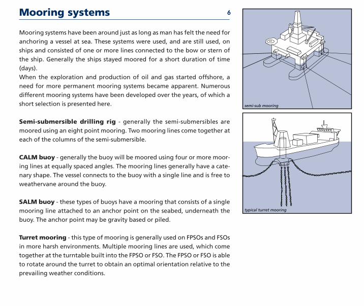
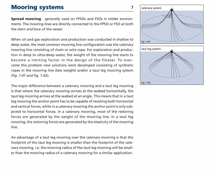
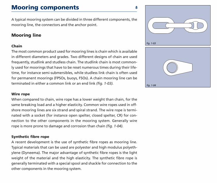
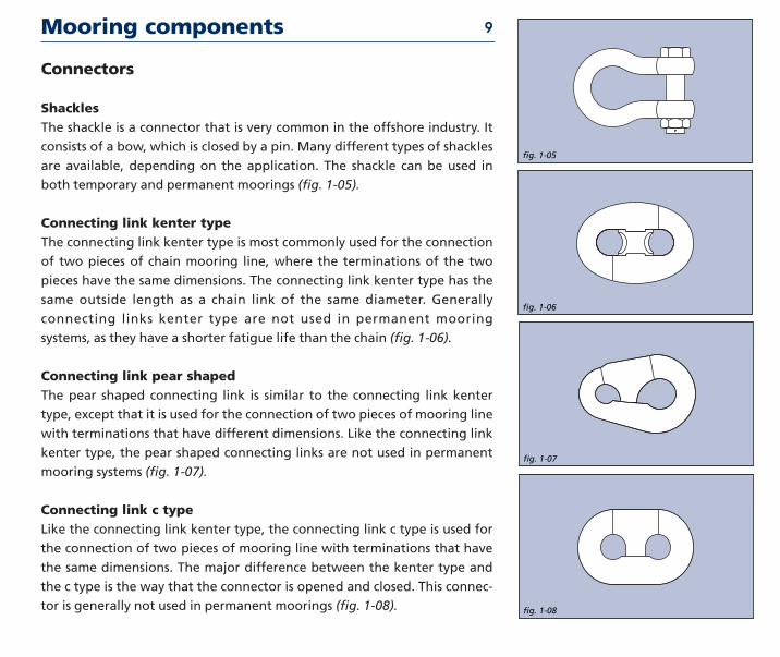
Mooring components
fig 1-05
fig 1-06
fig 1-07
fig 1-08
Connectors
ShacklesThe shackle is a connector that is very common in the offshore industry It
consists of a bow which is closed by a pin Many different types of shackles
are available depending on the application The shackle can be used in
both temporary and permanent moorings (fig 1-05)
Connecting link kenter typeThe connecting link kenter type is most commonly used for the connection
of two pieces of chain mooring line where the terminations of the two
pieces have the same dimensions The connecting link kenter type has the
same outside length as a chain link of the same diameter Generally
connecting links kenter type are not used in permanent mooring
systems as they have a shorter fatigue life than the chain (fig 1-06)
Connecting link pear shapedThe pear shaped connecting link is similar to the connecting link kenter
type except that it is used for the connection of two pieces of mooring line
with terminations that have different dimensions Like the connecting link
kenter type the pear shaped connecting links are not used in permanent
mooring systems (fig 1-07)
Connecting link c typeLike the connecting link kenter type the connecting link c type is used for
the connection of two pieces of mooring line with terminations that have
the same dimensions The major difference between the kenter type and
the c type is the way that the connector is opened and closed This connec-
tor is generally not used in permanent moorings (fig 1-08)
9
Mooring components
SwivelsA swivel is used in a mooring system generally of a temporary type to
relieve the twist and torque that builds up in the mooring line The swivel is
often placed a few links from the anchor point although it can also be
placed between a section of chain and a section of wire rope There are
many different types of swivels available although a disadvantage of most
common swivels is that they may not function while under load which is
caused by high friction inside the turning mechanism A new development is
swivels that are capable of swivelling under load due to special bearing sur-
faces inside the mechanism (fig 1-09)
Anchoring point
Dead weightThe dead weight is probably the oldest anchor in existence The holding
capacity is generated by the weight of the material used and partly by the
friction between the dead weight and the seabed Common materials in use
today for dead weights are steel and concrete (fig 1-10)
fig 1-10
13
fig 1-09
13
10
Mooring components
fig 1-12
13
Drag embedment anchorThis is the most popular type of anchoring point available today The drag
embedment anchor has been designed to penetrate into the seabed either
partly of fully The holding capacity of the drag embedment anchor is gen-
erated by the resistance of the soil in front of the anchor The drag embed-
ment anchor is very well suited for resisting large horizontal loads but not
for large vertical loads although there are some drag embedment anchors
available on the market today that can resist significant vertical loads
(fig 1-11)
PileThe pile is a hollow steel pipe that is installed into the seabed by means of a
piling hammer or vibrator The holding capacity of the pile is generated by
the friction of the soil along the pile and lateral soil resist-ance Generally
the pile has to be installed at great depth below seabed to obtain the
required holding capacity The pile is capable of resisting both horizontal
and vertical loads (fig 1-12)
fig 1-11
13
11
Mooring components
Suction anchorLike the pile the suction anchor is a hollow steel pipe although the diame-
ter of the pipe is much larger than that of the pile The suction anchor is
forced into the seabed by means of a pump connected to the top of the
pipe creating a pressure difference When pressure inside the pipe is lower
than outside the pipe is sucked into the seabed After installation the pump
is removed The holding capacity of the suction anchor is generated by the
friction of the soil along the suction anchor and lateral soil resistance The
suction anchor is capable of withstanding both horizontal and vertical loads
(fig 1-13)
Vertical load anchorA new development is the vertical load anchor (VLA) The vertical load
anchor is installed like a conventional drag embedment anchor but pene-
trates much deeper When the anchor mode is changed from the installa-
tion mode to the vertical (normal) loading mode the anchor can withstand
both horizontal and vertical loads (fig 1-14)
fig 1-13
13
fig 1-14
13
12
History of drag embedment anchorsHistory traces the use of anchors to China as far back as 2000 BC though it is quite probable that they
were used prior to this At that time the general tendency was to use large stones baskets of stones
bags of sand or even logs of wood loaded with lead which were then fastened to lines It was this
weight as well as a certain degree of friction on the bottom which secured a vessel in position
With the introduction of iron into anchor construction teeth or flukes were built on the anchor
allowing penetration into the seabed thus offering additional stability Yet these primitive
anchors were of poor construction and often broke under pressure Curved arms were intro-
duced in 1813 and from 1852 the so-called lsquoAdmiralty Anchorrsquo was used for ships of the Royal
Navy Another refinement in the 19th century was the elimination of the stock the crosspiece at
the top of an anchor which ensured that the positioning of the anchor would allow the flukes to
penetrate the soil A stockless anchor was invented in 1821 and became popular primarily as a
result of the ease of handling and stowing qualities still valued today
A large number of anchor types has been designed and commercialised over the years Some
have prospered others not The most recent designs are the results of vast experience and exten-
sive testing and are far more efficient than their historical predecessors A short overview of the
anchors in use today is presented on the following pages
History of embedment anchors 13
anchor shackle
shank
fluke
stabilisers
Based upon certain charateristics such as fluke area shank stabilisers it is
possible to classify the various anchor types To allow a rough comparison of
anchor type efficiency an indication () is provided for a 10 t anchor as (HOLDING
CAPACITY = WEIGHT EFFICIENCY)
Class A efficiency range 33 to 55
slender anchors with ultra-penetration
Characteristics of anchor types
StevprisClass A
Stevshark
FFTS
14
Class B efficiency range 17 to 25
anchors with lsquoelbowedrsquo shank allowing for improved penetration
Characteristics of anchor types
Bruce TS
Hook
Bruce SSClass B
15
Class C efficiency range 14 to 26
anchors with open crown hinge near the centre of gravity and relatively
short shank and stabilisers or built-in stabilisers
Characteristics of anchor types
Stevfix
Stevmud
Flipper Delta
StevinClass C
16
Class D efficiency range 8 to 15
anchors with hinge and stabilisers at the rear and relatively long shanks and
stabilisers
Characteristics of anchor types
LWT
Moorfast - Stato - Offdrill
Boss
DanforthClass D
17
Class E efficiency range 8 to 11
anchors with very short thick stabilisers hinge at the rear and a relatively
short more or less square-shaped shank
Characteristics of anchor types
Stokes
Snugstow
Weldhold
AC14Class E
18
Class F efficiency range 4 to 6
anchors with square shank no stock stabilisers The stabilising resistance is
built-in the crown
Characteristics of anchor types
Beyers
Union
Spek
US Navy StocklessClass F
19
Class G efficiency range lt6
anchors with small fluke area and stabilisers at the front of the shank
Characteristics of anchor types
Stock
Dredger
Mooring Anchor
Single Fluke StockClass G
20
History of vryhof anchor designs
A brief chronological summary of the types of anchors vryhof has designed
for use in the offshore and dredging industries
bull 1972 - The Stevin anchor The original design The wing was not yet
enlarged The anchor had a square shank It is no longer manufac-
tured
bull 1974 - The Hook anchor originally designed for permanent moorings
This design was surpassed in 1980 by the Stevpris design and is no
longer manufactured
bull 1977 - The Stevin Mk3 anchor is the improved version of the original
Stevin anchor It was equipped with an enlarged crown and fluke
area and a streamlined shank for more efficient penetration This
anchor is still manufactured and in use in offshore and dredging
activities It has all classification societies approvals
Stevin
Hook
Stevin Mk3
21
History of vryhof anchor designs
bull 1978 - The Stevfix anchor this anchor was designed with special fluke
points for harder soils and a larger fluke area than the Stevin but
has been surpassed by the Stevpris anchor It is no longer manufac-
tured
bull 1979 - The Stevmud anchor the Stevmud is essentially the Stevin anchor
with a considerably enlarged fluke area This anchor type was also
surpassed by the Stevpris anchor and is no longer manufactured
bull 1980 - The introduction of the Stevpris and Stevshark anchors The
Stevpris anchor is a deep penetrating anchor with a plough
shaped shank surpassing the performance of all earlier designs in
the vryhof range and incorporating the latest experience research
and knowledge of the anchor designer The Stevshark anchor is a
specially reinforced Stevpris anchor equipped with a serrated
shank and cutter-teeth for better penetration in hard soils such as
coral types or sandstone The fluke points are specially reinforced
to withstand high point loads
Stevmud
Stevpris
Stevfix22
History of vryhof anchor designs
bull1990 - The Stevpris Mk5 and Stevshark Mk5 were introduced The
improved versions of the original Stevpris and Stevshark anchors
Improvements have concentrated on two features higher holding
capacity and easier handling
bull1996 - Introduction of the Stevmanta VLA (Vertical Load Anchor) Based
on industry demand for an anchor that could withstand vertical
loads the Stevmanta VLA was developed The Stevmanta VLA is a
new design in which a traditionally rigid shank has been replaced
by a system of wires connected to a plate The anchor is designed to
accept vert ical (or normal) loads and is instal led as a
conventional drag embedment anchor with a horizontal load to
the mudline to obtain the deepest penetration possible By chang-
ing the point of pulling at the anchor vertical (or normal) loading
of the fluke is obtained thus mobilising the maximum possible soil
resistance As a VLA is deeply embedded and always loaded in a
direction normal to the fluke the load can be applied in any
direction Consequently the anchor is ideal for taut-leg mooring
systems
Stevshark Mk5
Stevmanta
23
Theory
2
TheoryAnchor design used to be based on practical experience of the anchor man-
ufacturer only Nowadays science has become a major factor in the design
process complementing the experience of the anchor manufacturer Based
on test results both in the laboratory and in the field a much better under-
standing of anchor behaviour has been achieved
The performance of an anchor is influenced by many different parameters
of which the following are only a few fluke area and design shank design
soil conditions load conditions type of mooring line
This chapter presents a short overview of how these parameters influence
the performance of the anchor It is by no means complete but it will give a
better understanding of how an optimal anchor design can be achieved In
the last part of this chapter a few relevant test results are presented
Introduction 25
Anchor holding capacity 26
fig 2-02
fig 2-01
fig 2-03
fig 2-04
Criteria for anchor holding capacityThe holding capacity of an anchor is governed by the following parameters
bull The fluke area which is limited by the strength of the anchor design
bullThe penetration of the anchor The penetration of the anchor is governedby the soil type (deep penetration in very soft clay and shallow penetra-
tion in sand) the anchor type (design) the type of mooring line that is
used (chain or wire rope) and the applied load
An increase in fluke area or an increase in the penetration depth of the
anchor results in a higher holding capacity
In the following paragraphs the influences on the anchor penetration are
further clarified
Streamlining of the anchorA streamlined anchor is very important for optimal penetration in the soil
As can be seen in fig 2-01 and fig 2-02 an anchor which has protruding
parts will encounter much more soil resistance and consequently will not
penetrate as deep as a more streamlined anchor with the same fluke area
Shank shapeA square shank which is common for most older type single shank anchors
will cause penetration resist-ance due to the fact that the soil can not pass
easily past the shank A clod of soil will form underneath the shank effec-
tively increasing the resistance of the soil (fig 2-03) Bevelling the shank
allows deeper penetrationWhen the single shank is replaced by a twin
shank construction (for instance Stevpris FFTS) usually two thin parallel
steel plates the soil can more easily pass through and past the shank and
consequently the twin shank anchor can penetrate deeper (fig 2-04)
Mooring lineAn anchor connected to a wire rope mooring line will penetrate deeper
than the same anchor connected to a chain mooring line (fig 2-05 and fig
2-06) This is caused by the higher lateral resistance (penetration resistance)
along the chain mooring line This effect is noticeable in all soil conditions
but especially in very soft clay where very deep penetration can be
obtained The holding capacity of a chain mooring line due to friction in
and on the seabed is larger than the holding capacity of a wire rope moor-
ing line
When an anchor reaches its ultimate holding capacity ie it will not resist
any higher loads at shallow penetration a wedge shaped piece of soil (in
front and above the anchor) will fail The holding capacity of the anchor can
then be described as a combination of the following parameters (fig 2-07
and fig 2-08)
bull The weight of the anchor (A)
bull The weight of the soil in the failure wedge (B)
bull The friction of the soil in the failure wedge along fracture lines (C)
bull Friction between fluke surface and soil (fluke area) (D)
bull The bearing capacity of shank and mooring line (E)
bull The friction of the mooring line in and on the soil (E)
Anchor holding capacity 27
fig 2-05
fig 2-06
fig 2-07
A
B
C
E
D
fig 2-08
Criteria for good anchor design
Anchor parameters can be scaled from geometrically proportional anchors
using the scale rules in table A
There are several attributes of an anchor which are crucial in assuring its
effective performance
bull The anchor must offer a high holding capacity a result of the fluke area
and shank design in combination with penetration and soil type
bull The design of the anchor should be such that the anchor is capable of
being used successfully in practically all soil conditions encountered over
the world ranging from very soft clay to sand corals and calcarenites
bull The flukeshank angle of the anchor should be easily adjustable allowing
the anchor to be quickly deployed in different soil conditions
bull The design must be so conceived and produced that the high loads com-
mon in practice can be resisted and that the anchor can be easily handled
installed retrieved and stored
bull The penetration of an anchor depends upon its shape and design
Obstructing parts on the anchor should be avoided as much as possible
bull The stability of an anchor encourages its penetration and consequently
its holding capacity Efficient stabilisers are an integral part of a good
anchor design
bull The shank must permit passage of the soil
bull The surface area of an anchor fluke is limited by the required structural
strength of the anchor
bull The anchor design must have optimal mechanical strength to fulfil
requirements and stipulations of the classification societies
bull The anchor should be designed to ensure an optimum between structur-
al strength of the anchor and holding capacity
bull The anchor should be streamlined for low penetration resistance
28
table A
Scale influence
Model Reality Related to Weight
Length L n W 13
Fluke area A n2 W 23
Weight W n3 W
Penetration P n W 13
Moment M n4 W 43
Moment of iner tia I n4 W 43
Section Modulus S n3 W
Bend ing stress MS n4n3=n W 13
Shear strength FA n3n2=n W 13
Aspects of soil in anchor design 29
Aspects of soil mechanics in anchor designUntil the nineteen seventies anchor design was largely an empirical process
There was not much science involved more use of experience It is not easy
for instance to calculate the Ultimate Holding Capacity (UHC) of an anchor
from the commonly known soil mechanics formulas The main problem is
the prediction of the volume of soil mobilised by the anchor To a large
degree it is this volume which determines the UHC Detailed understanding
of soil characteristics and behaviour is essential in the anchor design
process and of increasing benefit in handling at sea It is this understanding
which is the hallmark of a competent anchor designer and builder
For anchor design and installation the availability of good soil data is of
utmost importance as the soil is of great influence on anchor behaviour The
following are influenced by the soil conditions encountered
Anchor type - some anchors are more suited for soft soil conditions (soft
clay) while others are more suited for hard soils (sand and hard clays)
although there are a number of anchor types on the market that are suited
for most soil conditions encountered
Holding capacity - in hard soil like sand and hard clay the maximum
attainable ultimate holding capacity with a certain anchor type and size is
higher than the attainable ultimate holding capacity in very soft clay
Penetration and drag - in very soft clay the anchor will penetrate deeper
than in harder soil like sand As a consequence the drag length of the
anchor will also be longer in very soft clay than in hard soil
Retrieval forces - when an anchor is installed in very soft clay the required
retrieval forces will be higher than in hard soil like sand For example in
very soft clay the required retrieval force of an anchor can be equal to 80-
90 of the installation load while in hard soil (sand) the retrieval force
might only be 20-30 of the installation load
Soil classification 30 Undrained Shear Strength (kPa)
Consistency ASTM BSof Clay D-2488 CP-2004
Very soft 0 - 13 0 - 20
Soft 13 - 25 20 - 40
Firm 25 - 50 40 - 75
Stiff 50 - 100 75 - 150
Very stiff 100 - 200 150 - 300
Hard 200 - 400 300 - 600
Very hard gt 400 gt 600
table B
Soil strength is generally expressed in terms of the shear strength parame-
ters of the soil The soil type is classified mainly by grain size distribution
Grain size Soil descrip tionlt - 2 microm Clay2 - 6 microm Fine Silt6 - 20 microm Medium Silt
20 - 60 microm Coarse Silt60 - 200 microm Fine Sand200 - 600 microm Medium Sand06 - 2 mm Coarse Sand2 - 6 mm Fine Gravel6 - 20 mm Medium Gravel
20 - 60 mm Coarse Gravel60 - 200 mm Cobblesgt - 200 mm Boulders
IIn general the soil types encountered in anchor design are sand and clay
(Grain diameter from 01 microm to 2 mm) However mooring locations consist-
ing of soils with grain sizes above 2 mm such as gravel cobbles boulders
rock and such also occur Clay type soils are generally characterised by the
undrained shear strength the submerged unit weight the water content
and the plasticity parameters The consistency of clays is related to the
undrained shear strength However American (ASTM) and British (BS) stan-
dards do not use identical values (table B)
The undrained shear strength values Su can be derived in the laboratory
from unconfined unconsolidated tests (UU)
Soil classification 31
On site the values can be estimated from the results of the Standard
Penetration Test (SPT) or Cone Penetrometer Test (CPT) An approximate
relation between shear strength and the test values are shown in table C
The mechanical resistance of sandy soils is predominantly characterised by
the submerged unit weight and the angle of internal friction ϕ Theseparameters are established in the laboratory An approxim-ate correlation
between the angle ϕ and the relative density of fine to medium sand is given
in table D The undrained shear strength of clayey soil can also be estimated
based on manual tests
bull In soft clay the thumb will easily penetrate several inches indicating an
undrained shear strength smaller than 25 kPa
bull In firm (medium) clay the thumb will penetrate several inches with mod-
erate effort indicating an undrained shear strength between 25 kPa and
50 kPa
bull Stiff clay will be easily indented with the thumb but penetration will
require great effort indicating an undrained shear strength between 50
kPa and 100 kPa
bull Very stiff clay is easily indented with the thumbnail indicating an
undrained shear strength between 100 kPa and 200 kPa
bull Hard clay is indented with difficulty with the thumbnail indicating an
undrained shear strength larger than 200 kPa
The rock strength can generally be described by its compressive strength
(table E)
A classification system for soil based on the carbonate content and grain
size of the soil (Clark and Walker) is shown on the laste page of this chapter
Su UU SPT CPTkPa kPa N MPa
0 - 13 0 - 25 0 - 2 00 - 02
13 - 25 25 - 50 2 - 4 02 - 04
25 - 50 50 - 100 4 - 8 04 - 07
50 - 100 100 - 200 6 - 15 07 - 15
100 - 200 200 - 400 15 - 30 15 - 30
gt 200 gt 400 gt-30 gt30
table C
Descriptive Relative Angle SPT CPTterm Density ϕ N MPa
Very loose lt 015 lt 30 0- 4 0 - 5
Loose 015 - 035 30 - 32 4 - 10 5 - 10
Medi um dense 035 - 065 32 - 35 10 - 30 10 - 15
Dense 065 - 085 35 - 38 30 - 50 15 - 20
Very dense gt 085 gt 38 gt 50 gt 20
Descriptive term Compressivestrength qu [MPa]
Very weak lt 125
Weak 125 ndash 5
Moderately weak 5 ndash 125
Moderately strong 125 ndash 50
Strong 50 ndash 100
Very strong 100 ndash 200
Extremely strong gt 200
table D
table E
Flukeshank angle
The penetration of an anchor into a certain soil type is greatly influenced by
the selected flukeshank angle For hinging anchor types (Stevin Danforth
etc) the flukeshank angle is the angle between the anchor shackle the
hinge and the fluke tip The method for measuring the flukeshank angle
for fixed shank anchors (Stevpris FFTS etc) is not well defined Often it is
the angle between the anchor shackle the rear of the fluke and the fluke
tip but not all anchor manufacturers use the same definition
The recommended flukeshank angles for different soil conditions are pre-
sented in table F
Some modern anchors like the Stevpris Mk5 have an additional intermedi-
ate flukeshank angle of 41o which can be used in intermediate or more
complex soil conditions For instance at a location where the anchor has to
pass through a layer of soft clay before penetrating into a layer of sand
If an anchor is used with an incorrect flukeshank angle it will negatively
influence performance This is the case for all anchor types
In hard soil an anchor with a flukeshank angle of 320 will give the highest
holding power If an anchor is used with the flukeshank angle set at 500 the
anchor will fail to penetrate into the seabed and will begin to trip fall aside
and slide along the seabed (Fig 2-9 and 2-10)
32
fig 2-09
fig 2-10
Soil type Approximateflukeshank angle
Very soft clay 50˚
Medium clay 32˚
Hard clay and sand 32˚
table F
If an anchor is used in very soft clay (mud) with the flukeshank angle set at
32o the anchor will penetrate into the seabed however the penetration
will be less than when a flukeshank angle of 50o is used Consequently the
holding capacity will be lower when the flukeshank angle is set at 32o and
the drag length longer (Fig 2-11)
Flukeshank angle 33
fig 2-11
13
mud angle
sand angle
Because the fluke area of an anchor is of great influence on the holding
capacity it can be useful to compare the fluke area of different anchor
types that are available on the market today In general it can be stated
that two anchors of the same weight but of different type (for instance a
Stevin anchor and a Stevpris Mk5 anchor) do not necessarily have the same
fluke area Consequently two anchors of the same weight but different
type will have different holding capacities
Some examples
Fig 2-12 shows a Stevpris Mk5 anchor and a Moorfast anchor both of iden-
tical weight It demonstrates that in spite of being the same weight the
fluke areas differ substantially The ultimate holding capacity of the Stevpris
Mk5 anchor is 4 to 85 times higher than that of the same weight Moorfast
anchor
Fig 2-13 illustrates the difference in fluke area of the Stevpris Mk5 anchor
in comparison with the Bruce FFTS Mk4 anchor both of which have identi-
cal weight
Fluke area 34
fig 2-13
13
fig 2-12
13
Strength of an anchor design 35
Anchors should be designed to withstand the loads applied on them in the
different loading situations Typical loading situations and areas of special
attention for anchors are
bull During the proof loading of the anchors in the factory after construction
has been completed On basis of the proof load results the classification
societies issue the approval certificate
While embedded in the seabed
bull Depending on the soil conditions different loading situations can occur
on the anchor In sands and clays the load tends to be spread equally over
the anchor which generally presents no problems Retrieval is also very
simple without excessive loads placed on the anchor
bull In very hard soils the anchor has to be able to withstand the load with
only one or two of the fluke tips buried in the soil as penetration in very
hard soil conditions is generally shallow
bull In very soft clays (mud) penetration of the anchor is uncomplicated
However recovery of the anchor can cause high loads sometimes exceed-
ing the load that was used to install the anchor
bull Sidewards forces on the top of (shallow) buried anchors can be so
extreme that no anchor is capable of resisting them
During anchor handling
bull Care should be taken during the handling of the anchors as the loads
exerted by the winches vessels and chain can sometimes exceed the struc-
tural strength of the anchor and cause damage Anchor designers
attempt to design the anchors for these high loads however this is not
always possible due to variations in the magnitude of the loads during
handling operations
Strength of an anchor design 36
bull Large forces can be exerted on the anchor when high winch power is
used the anchor is caught on the anchor rack or caught behind the stern
roller of the AHV
bull The use of an improper anchorchaser combination When a chaser is used
that is either too small or too large the chaser could jam on the shank of
the anchor and cause damage
The strength of the Stevpris anchor is now more closely examined in the
light of the remarks made before
Strength of the shankThe prismatic shape of the Stevpris anchor not only ensures optimal pene-
tration of the soil but also guarantees maximum strength Although the
Stevpris design also has limitations it is one of the better designs to with-
stand sideward forces on the shank a frequent occurrence in practice
When using an anchor in very soft clay (mud) the bending moment on the
shank is low during the installation and when the anchor is in the soil
However during the breaking out of the anchor high bending moments
could be introduced in the shank due to the high retrieval forces required
in very soft clay In extremely sticky soils the breaking out force of the
anchor can rise to 80 or 90 of applied anchor load in certain instances
it can even exceed 100 To reduce these forces the breaking out proce-
dure is undertaken at low speed to allow time for the anchor to break out
Strength of an anchor design 37
Strength of the flukeThe strength of the fluke and especially the fluke points of an anchor are
very important when working in extremely hard soils such as coral lime-
stone and other rock types It is possible in such instances that the total
holding capacity of the anchor will have to be sustained by the fluke points
alone This means the structure must be strong enough to withstand
extreme bending forces Loading in normal soil conditions is not a problem
due to the fact that the load is equally spread over the fluke
In fig 2-14 the different force points are shown for varying soil conditions
The location on the fluke where the proofload is applied is also indicated
Strength in extremely hard soilsIn very hard soils such as calcarenite coral and limestone an anchor will not
penetrate very deeply Consequently the load applied to the anchor has to
be held by the fluke tips of the anchor and a small portion of the fluke This
means that extremely high loads will be applied to the fluke tips compared
to normal soil conditions such as sand and clay
For use in very hard soil conditions vryhof has designed the Stevshark
anchor a modified version of the Stevpris anchor To create the Stevshark
the Stevpris anchor has been strengthened consequently a Stevshark
anchor having the same outside dimensions and holding capacity as a
Stevpris anchor will be heavier
Strength calculations of the Stevshark design have been made to guarantee
sufficient strength in the fluke points The Stevshark anchor is designed to
withstand the application of the main part of the load on just its fluke tips
fig 2-14
rock
proofloadclay sand
Strength of an anchor design 38
To promote penetration the Stevshark anchor has a serrated shank and can
be provided with cutter points on the fluke tips Ballast weight can also be
added inside the hollow flukes of the anchor up to 35 of the anchor
weight This is important when working in very hard soil where the anchor
weight pressing on the fluke tips promotes penetration ie increased bear-
ing pressure
The loads in a mooring system are caused by the wind waves and current
acting on the floater Depending on the location of the floater in the world
different metocean conditions will prevail In the table below some
extreme metocean conditions are presented for different areas
The loads induced in the mooring system can be divided into quasi-static
loads and total dynamic loads The quasi static load is the load due to the
swell wind current and the frequency of the system For quasi-static loads
the systems tend to move at a low frequency generally with a period of 140
to 200 seconds
On top of this quasi-static load there are the individ-ual wave forces causing
a high frequency motion The high frequency motion causes dynamic shock
loads with a period of 10 to 14 seconds due to the rolling of the vessel and
the movements of the anchor lines through the water The quasi-static load
plus the individual wave forces is called the total dynamic load Generally
the quasi-static loads will be equal to 50 to 90 of the total dynamic load
See Fig 2-15 for an example of the difference between the quasi-static load
and the total dynamic load
Anchor loads and safety factors
fig 2-15
4000
3000
2000
1000
08300 8400 8500 8600 8700 8800 9800
389513Total dynamic
Quasi static13234213
13
Load
in k
N
Time in seconds
Location Waveheight Wave period Windspeed Currentm s ms ms
Campos Basin 8 ndash 10 12 - 15 25 1Gulf of Mexico 11 14 44 - 48 1Northern North Sea 15 - 16 15 - 17 38 - 39 09ndash 12
Porcupine Basin 16 - 18 16 - 20 39 - 41 10 ndash 15Vorine Basin 14 - 15 16 - 17 37 - 39 10 ndash 15West of Africa 4 - 6 10 - 16 20 03 ndash 06West of Shetlands 15 - 17 16 - 19 39 - 41 10 ndash 30
39
Anchor loads and safety factors
The quasi-static and total dynamic loads are generally calculated for the
intact and damaged load condition The intact load condition is the condi-
tion in which all the mooring lines are intact The damaged load condition
is the condition in which one of the mooring lines has broken
From the quasi-static load and the total dynamic load the required holding
capacity of the anchor can be calculated This is called the ultimate holding
capacity (UHC) for drag embedment anchors and the ultimate pull-out
capacity (UPC) for VLAs The required holding capacity is calculated by
applying the factors of safety specified by the classification societies
In the tables G and H the factors of safety are presented for the different
load conditions for drag embedment anchors (for instance the Stevpris Mk5
anchor) according to API RP 2SK The factors of safety used by the major
classification societies are generally similar to those given in API RP 2SK (2nd
edition 1996)
For VLAs the recently used factors of safety suggested by ABS are present-
ed in table I
The factors of safety for VLAs are higher than the factors of safety required
for drag embedment anchors due to the difference in failure mechanisms
When a drag embedment anchor reaches its ultimate holding capacity it
will continuously drag through the soil without generating additional hold-
ing capacity ie the load will stay equal to the UHC When a VLA exceeds its
ultimate pullout capacity it will slowly be pulled out of the soil
In table J the safety factors according to API RP 2SK for the mooring line are
presented for comparison purposes
40 Permanent Quasi-static Total dynamicmooring load load
Intact load condition 18 15
Damaged condition 12 10
Temporary Quasi-static Total dynamicmooring load load
Intact load condition 10 08
Damaged condition Not required Not required
VLA Total dynamicload
Intact load condition 20
Damaged condition 15
table G
table H
table I
Mooring line Quasi-static Dynamicsafety factors load load
Intact load condition 200 167
Damaged load condition 143 125
Transient load condition 118 105
table J
Drag embedment anchorsDrag embedment anchors are generally installed by applying a load equal to
the maximum intact load For permanent mooring systems the installation
load should be held for the period specified by the classification societies
(see table K) The anchor will then have penetrated to a certain depth but
will still be capable of further penetration because the ultimate holding
capacity has not been reached The anchor will also have travelled a certain
horizontal distance called the drag length After installation the anchor is
capable of resisting loads equal to the installation load without further pen-
etration and drag When the installation load is exceeded the anchor will
continue to penetrate and drag until the soil is capable of providing suffi-
cient resistance or the ultimate holding capacity has been reached However
there are certain effects which allow the anchor to withstand forces larger
than the installation load without further penetration and drag These are
The set-up and consolidation effectSet-up and consolidation mainly occur in clayey soils The penetrating
anchor disturbs the soil and the soil temporarily loses strength With time
the disturbed clay reconsolidates to its initial shear strength this takes from
a few hours up to 1 month depending on the soil type Because not all the
soil around the anchor is disturbed the set-up effect factor is less than the
sensitivity index indicates The disturbance mainly reduces the soil resis-
tance parallel to the fluke On reloading the parallel soil resistance gains
strength it takes a larger load to move the anchor again Equilibrium dic-
tates that also the normal load ie the bearing soil resistance to the fluke
increases consequently the load at the shackle increases also with the set-
up factor Observations on anchors for drilling rigs and theoretical consid-
erations for a 3 to 4 week consolidation time demonstrate a typical set-up
effect factor =15
Anchor behaviour in the soil 41 Classification Required duration ofsociety maintaining tension
Lloydrsquos Register of Shipping 20 minutes
American Bureau of Shipping 30 minutes
Det Norske Veritas (NMD) 15 minutes
table K
Anchor behaviour in the soil
The rate effect An increased rate of loading increases the soil resistance consequently the
anchor holding capacity increases This must be taken into account with
respect to total dynamic loads For anchor behaviour the rate effect factor
indicates how much higher the dynamic high frequency load may be with-
out causing extra movement of the anchor once installed at the installation
load The rate of loading influences pore pressure variations viscous inter-
granular forces and inertia forces Typical rate effect factors are 11 to 13
for total dynamic loads see Fig 2-16 where the rate effect is presented for
two different soil conditions (Su = 10 kPa and Su = 50 kPa)
Using the rate effect and set-up factors the behaviour of the anchor after
installation can be predicted more accurately
Vertical Load AnchorsA VLA is installed just like a conventional drag embedment anchor During
installation (pull-in mode) the load arrives at an angle of approximately 45
to 500 to the fluke After triggering the anchor to the normal load position
the load always arrives perpendicular to the fluke This change in load direc-
tion generates 25 to 3 times more holding capacity in relation to the instal-
lation load This means that once the required UPC of the VLA is known the
required installation load for the VLA is also known being 33 to 40 of
the required UPC
As a VLA is deeply embedded and always loaded in a direction normal to
the fluke the load can be applied in any direction Consequently the anchor
is ideal for taut-leg mooring systems where generally the angle between
mooring line and seabed varies from 25 to 450
42
fig 2-16
0
12
11
1
09
080 200 400 600 800 1000
Time factor St
Rat
e ef
fect
fac
tor
Su=10 kPa Su=50 kPa
Proof loads anchors
Proof loads for high holding power anchorsThe proof load according to Classification Societiesrsquo rules is applied at 13rd
of the fluke length and is carried out immediately on fabrication of the
anchor It is obtained by placing the anchor in a test yoke in which a
hydraulic cylinder applies the test loads controlled by a calibrated
manometer
(fig 2-17) The vryhof anchor types have been approved by the following
Classification Societies
bull The American Bureau of Shipping
bull Bureau Veritas
bull Det Norske Veritas
bull Germanischer Lloyd
bull Lloydrsquos Register of Shipping
bull Registro Italiano Navale
bull USSR Register of Shipping
bull Nippon Kaiji Kyokai
bull Norwegian Maritime Directorate
In the early days there were no specific regulations regarding the holding
power and strength of mooring anchors The rules which did exist were
often followed regardless of the type of vessel
Some anchors were approved as lsquohigh holding powerrsquo anchors This so-
called HHP approval was obtained after carrying out field tests in various
types of soil in which it had to be shown that an anchor provided a holding
power of at least twice that of a standard stockless anchor If an HHP anchor
was requested by the owner the anchor has proof tested in strict accor-
dance with the rules nothing more See table J for some examples of HHP
anchor proof loads A more detailed overview of HHP anchor proof loads is
fig 2-17
13
Anchor Proof Load Anchorweight fac tor weight
1 t 26 t 26 x
5 t 79 t 15 x
7 t 99 t 14 x
10 t 119 t 12 x
15 t 155 t 10 x
20 t 187 t 9 x
table J
43
Proof loads anchors
given in the product data section
The use of the specified proof loads for HHP anchors can lead to situations
where different types of anchors with the same holding capacity are proof
loaded at different loads see fig 2-18 From this figure it can be concluded
that the proof load of the anchors should preferably be related to the
break-load of the mooring line on the vessel
Nowadays the rules and regulations are far more rigid and the require-
ments have been substantially increased There are now special rules for
lsquomobile offshore unitsrsquo and lsquopermanently moored structuresrsquo
If anchors need mobile offshore units certification the following properties
may be required
bull Proof load of the anchors at 50 of the breaking load of the chain
bull Submission of a strength calculation of the anchor to the classification
society prior to commencing anchor production this includes determin-
ing the mechanical strength of the anchor as well as proving that the
applied material can withstand the proofload
bull A statement of documented holding power from the anchor supplier
bull Submittal of a Quality AssuranceQuality Control Manual
In fig 2-19 a mooring system is shown in which all of the components are
balanced The strength of the mooring line holding capacity of the anchor
and strength of the anchor are all in the correct proportion and comply with
the rules
44
fig 2-18
0 50 100 150 200 250
29 t Danforth
10 t Stevin Mk3
45 t Stevshark Mk5
4 t Stevpris Mk5
Proofload in t
Proofload HHP anchors UHC=250 t1313
fig 2-19
0 10 20 30 40 50 60 70 80 90 100
Breakload chain
Ultimate holdingcapacity anchor
Damaged load floater
Proofload chain
Pretensionload anchor
Intact load floater
Proofload anchor
Balanced mooring system API RP 2SK
Load in
Quality control 45
The application of more advanced and complex technology in anchor
construction has brought about requirements for a systematic approach to
quality Initiated by various authorities they are continuously refined and
followed up by operating companies such as vryhof anchor Like other
companies vryhof has become increasingly aware of the vital importance
of managerial aspects and their influence on the total quality-assurance
and control system
Design and fabrication of anchors for permanent moorings are in
accordance with the quality requirements of the Rules NSISO 9001 as
described in our Quality Assurance Manual Vryhof anchors obtained the
ISO 90012000 certificate No 29389-2008-AQ-NLD-RvA Rev1 issued by Det
Norske Veritas for lsquoDesign Manufacture of anchors and Sales of anchors
and mooring componentsrsquo
Quality control is maintained throughout production A compilation of
certificates is presented to a client upon completion of a project
Anchor tests
IntroductionIn addition to prac ti cal expe ri ence of users and asso ciates anchor tests are
one of the most reli able means of fore cast ing anchor per for mance and thus
mak ing a prop er choice of anchor type and size
Examining anchor tests that have been car ried out in the past cer tain
conclu sions can be made
bullMany tests were under tak en in which the results were record ed accu rate ly
bull Detailed reports how ev er have not been very com mon
bull Anchor tests of the past are not always easy to inter pret or com pare
because of dif fer ent soil and anchor types
bull Test results have not always been inter pret ed inde pen dent ly
bull The more tests results are strict ly com pared to prac ti cal results the bet ter
one can fore cast the hold ing power and gen er al beha vi our in prac tice
Vryhof is in the per fect sit u a tion of hav ing detailed test data avail able
togeth er with exten sive prac ti cal data obtained dur ing instal la tion and use
of anchors on pro jects on site
Research into anchor beha vi our and the ulti mate hold ing capac ity of
anchors is often car ried out by test ing a model anchor pref er ably fol lowed
by a full-scale test in the field The opti mal anchor test con sists of model tests
with 10 kg anchors fol lowed by full-scale tests with 1 t and 10 t anchors The
anchors should be pulled until the ulti mate hold ing capac ity is reached
It is obvi ous that full-scale test ing of anchors can be expen sive Large AHVs
strong winch es and strong moor ing lines are required which are not always
avail able For exam ple a 5 t Stevpris Mk5 anchor deployed in sand is
capable of stop ping a mod ern AHV at its full bol lard pull
46
Anchor tests 47
fig 2-20 Drag
Ho
ldin
g C
apac
ity A G B
C
D
E
F
Testing a 10 t Stevpris Mk5 anchor to its ulti mate hold ing capac ity in sand
would require a hor i zon tal pull ing capac ity of approx i mate ly 600 t
If anchor tests are to be com par able the test ing pro gram should pref er ably
meet as a min i mum the fol low ing cri te ria
bull An accu rate and sophis ti cat ed meas ur ing system should be used
bull The anchors should be test ed up to their ulti mate hold ing capac ity
bull Drag and pen e tra tion of the anchor should be record ed dur ing test ing
bull The anchor should be held under ten sion with a blocked winch for 15
min utes to inves ti gate any drop in hold ing capac ity
Reading test curvesThe beha vi our of an anchor dur ing ten sion ing can be accu rate ly inter pret ed
from the hold ing capac ity ver sus drag curve Sample test curves are pre sent ed
in Fig 2-20 Properly inter pret ed per for mance curves can explain a lot
about anchor beha vi our
bull Curve A is very steep and rep re sents a stream lined anchor in very stiff soil
bull Curve B is a nor mal curve for anchors in sand and medi um clay
bull Curve C is a curve of an unstable anchor This can be caused by a wrong
flukeshank angle set ting a short stab i lis er or a fluke that is too long
bull Curve D is a nor mal curve for an anchor in very soft clay
bull Curve E is an anchor with a 32o flukeshank angle in very soft clay
bull Curve F rep re sents an anchor that is turn ing con tin u ous ly This can be
caused by the absence of stab il is ers a too large flukeshank angle or a
low effi cien cy anchor at con tin u ous drag
bull Curve G rep re sents an anchor pen e trat ing in a layer of stiff clay over lain
by very soft clay
Anchor tests
Curves A B D E and G show a very stable ris ing line which indi cates that
the anchor builds up its hold ing capac ity con stant ly until the ulti mate hold ing
capac ity has been reached after which the anchor shows con tin u ous drag
The other curves are large ly self-explan a to ry
Test resultsVryhofrsquos exten sive data base of test results with dif fer ent anchor types sizes
and soil con di tions has been fre quent ly used in anchor design Data has
been obtained from prac tice scale mod els and from third par ties The data
has been inter pret ed and after wards incor po rat ed in the ulti mate hold ing
capac ity drag and pen e tra tion graphs of the Stevin Mk3 and Stevpris Mk5
anchor as well as in the ulti mate pull-out capac ity graph of the Stevmanta VLA
Norwegian Contractors (1984)In 1984 Norwegian Contractors car ried out tests at Digernessundet Stord
Norway The pur pose of these tests was to deter mine the cor rect anchor type
and size for the moor ing system of the Gullfaks A plat form dur ing the con struc -
tion of the plat form at Digernessundet Although the con struc tion would took
place at one loca tion it was known that three dif fer ent types of soil con di tions
would be encoun tered sand soft mud and an 8 m mud layer on rock After the
initial trials the Stevpris anchor was select ed for fur ther test ing
The 3 t Stevpris anchor that was used for the tests at a 330 pull ing angle
pro duced a max i mum hold ing capac ity of 150 t in the sand 102 t in the very soft
clay and 150 t in the layer of mud on rock As the moor ing system required
a sur vi val load of 1500 t a 65 t Stevpris (mud loca tion) 40 t Stevpris (sand
loca tion) and 60 t Stevshark (mud on rock loca tion) were select ed for the final
moor ing Fig 2-21 shows the test results of the 3 t Stevpris anchor while fig 2-22
shows the result of the ten sion ing of the final anchors with a load of 820 t
48
fig 2-21
150
100
50
250 10 20 30 40
Sand8 m soft clay 13on rock1313
Ho
ldin
g c
apac
ity
in t
soft clay1313
Drag in meters
fig 2-22
800
700
600
500
400
300
200
100
0
20 40 60 80
Full scale Gullfaks A anchors
Ho
ldin
g c
apac
ity
in t
Drag in meters
A B C
A = 40 t Stevpris in sand
B = 60 t Stevshark in mud on rock
C = 65 t Stevpris in mud
Survival load = 1500 ton
Final pretension load on site
Anchor tests 49
fig 2-23
700
600
500
400
300
200
100
0 50 100 150 200 250 300 350 400 450 500
Drag distance in feet
7-2
7-3
7-47-1
2-2
2-1
Large scale anchor test jip - 7 amp 2 t
Ho
rizo
nta
l lo
ad in
kip
s
Large scale anchor tests in the Gulf of MexicoIn 1990 tests were per formed with 2 t and 7 t Stevpris Mk5 anchors as part
of an anchor test Joint Industry Project (JIP) The anchors were test ed using
a wire rope fore run ner
The 2 t Stevpris anchor was test ed up to its ulti mate hold ing capac ity of 107 t
(235 kips) Due to insuf fi cient pull ing capac ity the 7 t Stevpris anchor could not
be pulled up to its ulti mate hold ing capac ity Based on the results of tests the
ulti mate hold ing capac ity of the 7 t Stevpris anchor was cal cu lat ed to be larg er
than 338 t (745 kips) (fig 2-23)
Anchor tests
UpliftStevpris anchors are well capable of resist ing uplift loads when they are deep -
ly embed ded Anchors in sand and firm to hard clays do not pen e trate very
deeply and only take small uplift loads Stevpris anchors installed in very soft
clay and mud pen e trate deeply a typ i cal pen e tra tion for a 15 t anchor is 15 to
25 meters Due to the inverse cat en ary in the soil the anchor line arrives at the
anchor shack le at an angle of 20o to 30o with the mud line Once the anchor is
installed a load mak ing an angle up to 20o with the hor i zon tal at mud line will
not change the load ing direc tion at the anchor A Stevpris anchor has been
test ed in the Gulf of Mexico with grad u al ly increas ing pull angle (fig 2-24)
The max i mum resis tance was obtained for 18o uplift at mud line
50
fig 2-24
13
35 000
30 000
25 000
20 000
15 000
10 000
5 000
0
60
50
40
30
20
10
0
0 50 100 150 200 250 300
= dyn load13= pull angle
Lin
e an
gle
vs
mu
din
e
Line length pulled in feet
Lin
e lo
ad in
lbs
18˚13
Cyclic effect fac torThe load ing at the anchor is cyclic Exxon per formed cyclic tests on anchors
report ed by Dunnavent and Kwan 1993 Although the max i mum cyclic load
was less than the initial instal la tion load the stat ic load applied after the
cycling phase revealed 25 to 50 larg er anchor resis tance than the initial
instal la tion load (fig 2-25) This effect is explained by fur ther pen e tra tion
of the anchor Applying this knowl edge to the anchors the stat ic anchor
resis tance after some storm load ing improves by the cyclic effect fac tor of
125 to 15
Anchor tests 51
fig 2-25
015
01
000 50 100 150 200 250 300 350
Time in seconds
An
cho
r re
sist
ance
in k
N
Initial static capacity
Cycling
Increased capacity13vs initial static
Anchor tests 52
fig 2-26
200
150
100
50
0
0 5 10 15 20 25 30 35
13
Line length pulled in feet
Block winch
13Change mode13
13
Lin
e lo
ad in
13900 pulling 13angle with 13seabed in 13normal 13loading 13mode
Tests with Stevmanta anchorsTests have been per formed in the Gulf of Mexico and offshore Brazil The
Stevmanta anchor being pulled in with a load equal to F accept ed a ver ti cal
load to the anchor of up to 2 times F Amongst the many tests the anchor
relax a tion was meas ured The anchor with a fluke area of 013 m2 was
pulled in at 0o pull angle (fig 2-26) then load ed ver ti cal ly to a load equal to
16 times the max i mum instal la tion load At this load the winch was
blocked
Anchor tests 53
fig 2-27
200
150
100
50
0
2000 2200 0 00 2 00 4 00 6 00 8 00
Time in hours
Lin
e lo
ad in
13Change from 13pull-in to normal mode 1313
13Block winch 1313
13900 pulling 13angle with 13seabed in 13normal 13loading 13mode
This per mit ted the mon i tor ing of the load with time (fig 2-27) as what
would be expect ed in real cir cum stanc es at a con stant load ed anchor line
The results show that the hold ing capac ity of the anchor does not change
sig nif i cant ly dur ing con tin u ous load ing as the observed decrease in ten sion
was due to move ment of the winch The sub se quent pull ing at 700 AM
showed that for only a small move ment the full plate capac ity (2 x instal la -
tion load) could be reached Continuous pull ing caused the anchor to loose
resis tance and break out
Anchor tests
To dem on strate that the fea ture of these anchors is not only a ver ti cal resis -
tance the anchor was installed with a hor i zon tal pull the mode changed to
the nor mal (ver ti cal) mode and the anchor sub se quent ly pulled with an
uplift angle of 30o (fig 2-28) The beha vi our is sim i lar to the ear li er ver ti cal
pull test However for the 30o pull angle the anchor did not break out but
moved slow ly along the pull ing direc tion through the soil The graphs clear -
ly show this effect and that the anchor can be used for sub stan tial hor i zon -
tal loads
54
fig 2-28
13
200
150
100
50
0
0 5 10 15 20 25 30 35 40
Line length pulled in feet
13Change from 13pull-in to normal mode 1313
Lin
e lo
ad in
13300 pulling 13angle with 13seabed in 13normal 13loading 13mode
Soil table
Increasing lithification
Increasing grain size of
particulate deposits
000
2 mm
006
3 mm
2 mm
60 m
m
Carbonate silt
Carbonate sand
Carbonate grave
l
Carbonate clay
Silic
eous ca
rbonate
Silic
eous ca
rbonate
silt
sand
Mixed
carbo
nate and
non-carbonate gravel
Calca
reous clay
Calca
reous silic
a silt
Calca
reous silic
a sand
Clay
Silic
a silt
Silic
a sand
Silic
a grave
l
Calcilutite
Calcisiltite (carb
Calca
renite (carb
Calciru
dite (carb
(carb Calysto
ne)
Siltstone)
Sandstone)
Conglom Or Breccia
Conglomeratic
Claye
y ca
lcilu
tute
Silic
eous ca
lcisiltite
Silic
eous ca
lcaren
ite
calcirudite
Calca
reous
Calcareao
us clay
stone
Calca
reous siltstone
Calca
reous sandstone
conglomerate
Conglomerate or
Claysto
ne
Siltstone
Sandstone
breccia
Fine-grained
lim
esto
ne
Detrital lim
esto
ne
Conglomerat
limesto
ne
Fine-grained
Fine-grained
silice
ous
Silic
eous detrital
Conglomerate
agrilla
ceous lim
estone
limesto
ne
limesto
ne
limesto
ne
Calca
reous
Calcareous clay
stone
Calca
reous siltstone
Calca
reous sandstone
conglomerate
Conglomerate of
Claysto
ne
Siltstone
Sandstone
Breccia
Crystallin
e lim
esto
ne or marble
Conve
ntional m
etam
orp
hic nomen
clature applie
s in this sec
tion
Approx Rock Very weak Weak to moderately weak Moderately strong to strong Strong to extemelystrength strong
Cementation of Very weak to firmly Well cemented soil (well cemented)soil cemented soil rock
Total carbonate content
90 50 10 90 50 10 90 50 10 50
55
Practice
3
PracticeAlthough theoretical knowledge of anchors is essential for good anchor design
and selection the practical issues are just as important The handling of an
anchor and the selection and use of support equipment is of equal importance
Anchor handling is a critically important and often complicated process It is
influenced by such factors as the weight and shape of the anchor the nature
of the soil the depth of the water the weather conditions the available
handling equipment and the type and weight of mooring line It is for these
reasons that anchor handling is a subject which requires careful considera-
tion Without proper anchor handling optimal performance of an anchor is
not possible
In the process of handling anchors various types of support equipment are
necessary or beneficial An anchor manual would be incomplete without
consideration of these auxiliary items the reasons for their use their oper-
ation and the advantages and drawbacks involved
This chapter gives an overview of the recommended procedures that should
be followed for anchor handling and the types and use of the support
equipment during the handling operations The following handling
procedures are by no means complete but they do give some suggestions
which can be applied to each anchor handling procedure and adapted for
specific circumstances and locations
Some of the topics covered in this chapter are
requirements for a soil survey connection of the anchor to the mooring
line chasers handling the Stevpris anchor handling the Stevmanta anchor
the Stevtensioner anchor handlingsupply vessels
Introduction 57
Soil survey 58Typical contents survey report
bull Cone pen e tra tion resis tance
bull Sleeve fric tion
bull Pore pres sure
bull SPT val ues
bull Gra nu lom e try and per cent age fines
bull Wet and dry den sities
bull Water con tent
bull Drained and undrained tri ax al tests
bull Undrained shear strength also remould ed
bull Uncon fined com pres sion tests
bull Plas tic ity lim its
bull Spe cif ic grav ity
bull CaCO3 con tent
bull Shell grad ing
bull Angu lar ity and poros ity
bull Com press ibil ity
bull Cemen ta tion
bull Nor mal ised rock hard ness test (point load test)
bull RQD index rock qual ity des ig na tion
table K
For the dimen sion ing of drag embed ment anchors the avail abil ity of site-spe -
cif ic soil data is impor tant For advice on spec i fy ing drag embed ment anchor
typesize and cal cu lat ing expect ed beha vi our the site-spe cif ic soil data should
be com pared with soil data of pre vi ous drag embed ment anchor (test) sites
The soil sur vey require ment for the design of drag embed ment anchors usu al ly
con sists of only shal low bore holes while in anchor pile design deep bore holes
are required For suc tion anchor design therefore a more exten sive soil
inves ti ga tion is generally required when com pared to drag embed ment anchors
When choos ing between anchor pile suc tion anchor and drag embed ment
anchor the finan cial impli ca tions of the soil sur vey should be taken into account
A typ i cal soil sur vey for drag embed ment anchor design requires a sur vey
depth of twice the length of the fluke in sand and 8 times the fluke length
in very soft clay In most cases a depth of 8 to 10 meters is suf fi cient
although in very soft clay a recon nais sance depth of 20 to 30 meters should
be con sid ered For opti mal drag embed ment anchor dimen sion ing each
anchor loca tion should ideal ly be sur veyed The soil inves ti ga tion can con -
sist of bore holes vib ro cores cone pen e tra tion tests or a com bi na tion of
these Cone pen e tra tion tests includ ing sleeve fric tion are pre ferred but
they should be accom pa nied by at least one vib ro core or sam ple bore hole
per site to obtain a descrip tion of the soil Depending upon the type of sur -
vey per formed and the soil con di tions encoun tered the sur vey report
should present the test results obtained on site and in the labor a to ry includ -
ing the points as shown in table K
It is pos sible to dimen sion the drag embed ment anchors based on lim it ed
soil infor ma tion (for instance fewer bore holes) The lsquolackrsquo of soil data can be
com pen sat ed by choos ing a con ser va tive (larger) anchor size
Pile or anchor 59
The choice between piles and anchors is only pos sible for per ma nent
systems Piles are not a good invest ment when an anchored entity must be
moved But the choice is often made for piles on emo tion al grounds a pile
does not drag However anchors that are prop er ly pre-ten sioned on site
will also not drag
While it is a psy cho log i cal ly load ed sub ject expe ri ence has shown that the
choice between anchor and pile is mere ly a mat ter of eco nom ics The
required pile weight for a system is equal to the required weight of a
Stevpris anchor Piles cost about 40 of equiv a lent capa bil ity anchors
However the instal la tion costs for piles are much high er Piles require a fol -
low er and a pile ham mer The instal la tion spread for piles is much more sig -
nif i cant a crane barge with sup port spread ver sus the two anchor han dling
ves sels The weath er downtime for a spread involv ing a crane ves sel is much
long er than when AHVs are used To allow drag of the anchors dur ing pre -
ten sion ing extra chain length is required Sometimes the pre ten sion load
for piles is much less than for anchors The sur vey work for anchors is gen er -
al ly much sim pler than for piles When aban don ing a field anchor remov al
is much cheap er than remov al of installed piles The choice between piles
and anchors strong ly depends upon the cir cum stanc es The table L can help
in esti mat ing the costs for the two alter na tives
Suction piles are an alternative for drag embedment anchors and piles also
for MODU applications The advantage is the accurate positioning of the
suction piles The disadvantage is the cost of the pile itself and the cost of
the installation
Description Pile Suction Anchorpile
Soil survey - - +
Procurement + - -
Installation spread - - +
Installation time - - +
Pile hammer - + +
Follower - + +
Pump unit + - +
Pretensioning + - -
Extra chain + + -
Rest value pileanchor - + +
Removal of anchor point - + +
ROV + - +
+ less expensive - more expensive
table L
Mounting instructions Stevpris Stevshark Mk5
A1pin 1 pin 2
pin 3 pin 4B1 B2
A2
13
Forward fluke-shank connectionRemove the locking plates A1 and A2 which are tack-welded to the fluke
Aft fluke-shank connectionMove the pins 1 and 2 to the outer side Remove the split pins and open
the locking plates B1 and B2 Move the pins 3 and 4 to the outside
60
Plate A1 amp A2
Pin 1 amp 2
Plate B1 amp B2 Pin
3 amp 4
Fit the rear shank lugs into the fluke by means of a crane Manoeuvre the
rear shank lugs with the notch into the gap in the flukes as indicated in
the figures When in position rotate the shank forward to align the front
pins with the shank
AttentionMake sure the serial number of the shank corresponds with the serial num-
ber of the fluke for reason of identification and certification
Align pins 1 and 2 with the forward shank eyes Move pins 1 and 2 back into
position Place the shank in the sand middle or mud position Align pins 3
and 4 with the rear shank lugs Move pins 3 and 4 back into position Fit and
weld the locking
plates A1 and A2
on the fluke See
welding detai l
below Close the
locking plates B1
and B2 and secure
with split pins
Vryhof recommended welding procedure for locking plates A1 and A2Fillet weld with electrode accAWSE7018
Welding process SMAW electrode
welding position 2F
material S355J2G3 (St52-2N)
preheat material 50deg C
interpass temp max 250deg C
Mounting instructions Stevpris Stevshark Mk5
13
Serial number
Sand angle Middle angle Mud angle
Locking plate
61
Mud
Middle
Sand
Notch
Mounting instructions Stevspris Mk6
13
A1pin 1 pin 2
pin 3 pin 4
A2
13
Plate A1 amp A2
Pin 1 amp 2
Forward fluke-shank connectionRemove the locking plates A1 and A2 which are tack-welded to the fluke
Aft fluke-shank connectionMove the pins 1 and 2 to the inner side Remove the splitpins and nuts
from pins 3 and 4 and move the pins 3 and 4 to the outside
62
1 2 3 4
Fit the rear shank lugs into the fluke by means of a crane Manoeuvre the
rear shank lugs into the gap in the flukes as indicated in the figures When
in position rotate the shank forward to align the front pins with the
shank
AttentionMake sure the serial number of the shank corresponds with the serial num-
ber of the fluke for reason of identification and certification
Align pins 1 and 2 with the forward shank eyes Move pins 1 and 2 back into
position Place the shank in the sand middle or mud position Align pins 3
and 4 with the rear shank lugs and insert them in the lugs Tighten the bolts
and insert splitpins 3 and 4 Fit and weld the locking plates A1 and A2 on the
fluke See welding detail below
Vryhof recommended welding procedure for locking plates A1and A2Fillet weld with electrode accAWSE7018
Welding process SMAW electrode
welding position 2F
material S355J2G3 (St52-2N)
preheat material 50deg C
interpass temp max 250deg C
Mounting instructions Stevspris Mk6
13
Sand angle Middle angle Mud angle
Mud eye
13
Mid eye
Sand eye
Locking plate
63
Setting the flukeshank angle
Introduction
In soil such as sand and medium to hard clay an anchor with a flukeshank
angle of 32o will give the highest holding power An anchor with a 50o
flukeshank angle in this soil will not penetrate but will drag along the
seabed If used in mud a 50o flukeshank angle is appropriate An anchor with
a 32 o flukeshank angle will penetrate less and generate lower holding
capacity in mud(fig 3-01)
The Stevpris Mk5 anchor has an additional flukeshank angle setting of 41o
which can be adopted in certain layered soil conditions (table M)
Changing the flukeshank angle on the Stevpris Mk3
This can be carried out within half an hour with the Stevpris anchor upside
down on deck
Secure the anchor on deck Connect a tugger wire (C) to the holes (D) on the
bottom side of the fluke Change from mud to sand angle by removing the
locking plates and the two rear pins in (B) decrease the flukeshank angle
by hauling the cable (C) Reinstall the pins and locking plates in (A) Seal
weld the lock-ing plates do not weld them to the pins (fig 3-02)
64
fig 3-01
no penetration
D
fluke angle too large in hard soil
change from mud to sand angle
fig 3-02
Soil type Optimalflukeshankangle setting
Very soft clay (mud) 500
Certain layered soils 410
Medium to hard clay
or sand 320
Stevpris Mk5 only
table M
Setting the flukeshank angle 65
Change from sand to the mud position increase angle by veering (C) change
over pin and locking plates from (A) to (B) No special welding requirements
(fig 3-03)
Changing the flukeshank angle on the Stevpris Mk5 Changing the
flukeshank angle on the Stevpris Mk5 anchor is even quicker No welding
required Veering and hauling (C) to change the flukeshank angle as
above the pin however remains in (A) the locking plate is secured by means
of a cotter pin (fig 3-04)
change from sand to mud angle
fig 3-03
change flukeshank angle Stevpris Mk5
fig 3-04
Connecting a swivel to the Stevpris anchorTo connect a swivel to the Stevpris anchor several different configurations
are possible These are
Type I - The swivel is connected directly to the shank of the anchor thus
omitting the anchor shackle (fig 3-05)
J swivel shackle C end link B enlarged link A common link
Type II - The swivel is connected to the anchor shackle (fig 3-06)
J swivel shackle C end link B enlarged link A common link
Type III - The swivel is connected to the anchor shackle via a special design
end link
(fig 3-07)
K special end link J swivel C end link B enlarged link A com-
mon link
Type IV - The swivel is part of a forerunner connected to the anchor shack-
le for instance the forerunners VA02 VA04 and VA 06 described
in the product data section (fig 3-08)
PL pear link A common link B enlarged link H swivel
When a chaser is used in combination with the Stevpris and swivel some of
the configurations mentioned above are more suitable than others In gen-
eral swivels are only designed to withstand longitudinal forces and are
usually not designed for use in combination with chasers The design of the
chaser tends to stop it at the swivel Consequently there will be high
bending forces on the swivel which can result in damage or even breakage
Connecting a swivel 66
J C B A
fig 3-05
fig 3-06
J C B A
fig 3-07
K J C B A
fig 3-08
P L A B H B A
Generally it is best when the swivel is fitted some distance from the anchor
when a chaser is used The chaser can then pass the swivel and stop on the
anchor shank When a load is applied to the chaser the swivel is only loaded
longitudinally This means that in combination with the use of a chaser the
configuration type III and type IV are preferred
When the swivel (or swivel forerunner) is connected to the anchor shackle
by means of an end shackle and a chaser is used the end shackle and the
anchor shackle should be connected bow through bow instead of pin
through bow as is normal practice This to minimise the chance of damage
to the shackles
The illustrations fig 3-09 through fig 3-14 show how and how not to
connect the swivel to the Stevpris anchor when using a chaser
(See next page for fig 3-13 and 3-14)
Connecting a swivel 67 damage possible
fig 3-09
NO
fig 3-10
damage possible
fig 3-11
fig 3-12
NO
Connecting a swivel
The best method for chasing with a swivel in the system is to maintain the
tension of the anchor line as much as possible during chasing This will make
the chaser pass more easily over the swivel
68 damage possible
fig 3-13
fig 3-14
NO
Chasers 69
Chasers and their applicationTo facilitate handling pendant wires may be applied to retrieve the anchor
These wires are connected to a pendant eye situated on the anchor and
equipped with a buoy for picking up In deeper water higher anchor
break-out forces are encountered resulting in longer heavier pendant
wires and consequently larger buoys Due to wear caused by the continuous
movement of the buoy by the waves these pendants will break close to the
buoy The buoys would then float free and the anchors are much more
difficult to recover
To overcome this chasers were introduced These were rings lsquochasedrsquo along
the cable towards the anchor and back again to a rig or handling vessel
Their function was to ensure both installation and break-out of the anchor
without having to use a pendant linebuoy The chaser system thus totally
eliminates buoys partly eliminates cables and reduces wear on the system
The cost of a chaser is small when compared to the cost of a mooring line It
is therefore extremely important from an operatorrsquos viewpoint that chasers
do not inflict damage to the mooring lines
Chasers 70
Towing a chaser along mooring lines with at times high interface
pressures must result in wear It is thus essential that such wear is taken by
the chaser and not the mooring line The chasers vryhof recommends are
manufactured in a material that is softer than the steel used for the
mooring line Chaser wear is induced by the application of high interface
pressure between the mooring line and the chaser High interface pressure
can arise from
bull Pulling the chaser along a slack mooring line
bull Maintaining high tension in the chaser workwire when chasing a
tensioned mooring line
Chasing operations are best carried out on mooring lines which are fully
tensioned There is little need for the application of high interface pressure
while chasing the permanent chaser is captive on the mooring line and
unlike the J-chaser will not become disengaged due to a slack work wire
For optimum chasing operations the length of the chaser pendant line
should be at least 15 times the waterdepth
There are many different types of chaser available on the market today
A selection of the different chaser types is described in more detail on the
following pages
Chaser types 71
fig 3-16
fig 3-15
The J-chaserThe J-chaser (fig 3-15) is used on mooring lines where the anchor has to be
recovered and no permanent chaser has been installed or the normal
recovery mechanism has failed In other cases the J-chaser is used simply to
keep a chain free from a pipeline during deployment of the anchors The
chaser is deployed over the stern roller of an AHV at approximately 13 of
the water depth The chaser is towed across the mooring catenary until it
catches the chain It is then towed into contact with the anchor shankfluke
for anchor break-out and retrieval
The permanent chain chaserAs a practical alternative to the buoy and pendant the permanent chain
chaser (fig 3-16) was introduced Originally simple shackles were used
these were followed by special cast oval rings which were attached to a pen-
dant by a lsquobightrsquo of chain and shackle Very soon afterwards the pear-shaped
chaser with shackle eye was introduced The design of these chasers offers
superior sliding and penetration properties
Chaser types 72
fig 3-18
The detachable chain chaserFor rigs in service it is sometimes preferred to equip the mooring with a
chaser which does not require the anchor chain to be broken and re-made
Detachable chain chasers (fig 3-17) were introduced to satisfy this need
The withdrawal and replacement of the single bolt permits easy assembly of
the chaser on the mooring cable
The permanent wire chaserThe permanent wire chaser (fig 3-18) was introduced when rigs moved to
deeper waters and composite wirechain mooring systems became neces-
sary The chaser incorporates a lsquorockerrsquo which is centrally mounted on a
hinge bolt The rocker has two opposing grooves and when the chaser is
engaged with the mooring line the wire slides through one of these
grooves irrespective of the angle which the chaser makes with the mooring
The large radius at the base of the groove assists in reducing wear of the
rocker and avoids severe lsquoopeningrsquo of the lay of the wire if a loop of wire is
pulled during the handling process The material of the rocker is not as hard
as the material of the wire This means that wear is taken by the rocker
without damage to the wire and because the rocker is easily removable
replacement is relatively inexpensive The permanent wire chaser is easily
detachable by removal and re-assembly of the hinge bolt and rocker
Some designs of wire chaser incorporate fully rotating rollers over which
the mooring wire passes To be effective such rollers need to be of a large
diameter and require to be supported by bearings They are consequently
larger heavier and much more costly than the permanent wire chasers dis-
cussed above and because of their size they require more power at the
AHV to penetrate the seabed and reach the anchor
fig 3-17
Chaser types 73
fig 3-19
The J-lock chaserThe J-lock chaser (fig 3-19) has been designed so that it can slide along the
chain in one direction and when the pulling direction is reversed the chas-
er locks on the chain and does not slide any further This means that the
tension in the mooring line can be wholly transferred from the rig to the
chaser The J-shape permits catching the anchor chain after the anchor has
been installed This means that this chaser can be used to assist in unforeseen
circumstances The well-balanced and lsquoguidingrsquo design of the chaser enables
catching the chain when the chaser approaches a mooring at a point where
the catenary angle is as high as 450
When a normal permanent chaser is used under unforeseen conditions
there is the chance that the AHV cannot break out the anchor by means of
the chaser The J-lock chaser can help in such an instance It is released from
a second AHV and slides along the chain towards the anchor The design
prevents the J-lock chaser from sliding back The J-lock chaser is stopped at
the permanent chaser If the winch pull of both tugs is now increased the
J-lock chaser prevents the permanent chaser from sliding away from the
anchor Consequently the forces required do not increase and the anchor
can easily be broken out After this operation the J-lock chaser can be released
again
This chaser can also be used when a very heavy chain has to be installed It
assists during installation by lifting the chain
Stevpris installation 74
fig 3-20
chaser
fig 3-21
always deck anchor with chain between flukes
D
fig 3-22
quickly pass drum
D
fig 3-23
triangular plates on drum
D
Stevpris deployment for MODUs
IntroductionTypical methods for deployment and retrieval of Stevpris anchors with an
anchor handling vessel (AHV) are described focusing on the use of chasers
for handling the anchor (fig 3-20) This is the most common practice on
mobile drilling rigs (MODUs) Handling using permanent pendant lines is
similar
Deployment procedures for the Stevpris anchor will also be given for
permanent moorings where chasers are normally not used
Laying anchorsIt is preferred and by some operators required to deck the anchor before
run out to check the jewellery Run the anchor line out the full distance with
anchor on deck or on roller with the chain between the flukes (fig 3-21)
Boat increases power until anchor line tension rises on rig winch tension
meter When rig gives order to lower the anchor veer pendant till anchor
arrives at roller Allow the anchor some speed to negotiate the bump at the
change-over from the deck on to the roller (fig 3-22)
If anchor is kept on roller keep triangular plates below the main shackle on
the drum for stability of the anchor Alternatively the chaser can be kept on
deckroller In this situation the propeller thrust passes underneath the
anchor and does not influence the fluke (fig 3-23)
Stevpris installation 75
fig 3-24
STOP
fig 3-25
fig 3-26
wait for signal rig
D
Reduce propulsion momentarily when anchor passes the propeller thrust
keep chaser on anchor head for control of anchor orientation and lower
anchor (fig 3-24)
Once below the propeller wash zone reactivate and maintain propeller
thrust to well above 30 tons Keep constant tension in order to ensure
anchor does not fall through chaser ie anchor remains in the chaser and
orientation of the anchor is correct (fig 3-25)
Note In some circumstances AHVs prefer to run the anchor hanging from
the pendant line below the propeller wash approximately 60 to 80 meter
above the seabed This method requires less power on the winch during the
actual laying of the anchor If this method is employed make sure that at all
times the anchor is correctly oriented in the chaser Keep constant tension
in the pendant line to prevent the anchor from falling through the chaser and
possibly turn
Stop lowering when anchor hangs 10 to 15 meter above the bottom and
advise rig Rig now instructs AHV to pay out until pendant line is 14 to 15
times the water depth in shallow water (100m) and 13 to 14 times in deep-
er water AHV increases power till tension is again seen to rise at the rig ie
the load in the line is larger than the chain-soil friction (fig 3-26)
Rig commences to pull in slowly AHV further increases power until tension
rises further at rig winch At this moment rig orders AHV to lay the anchor
AHV immediately stops the propulsion and is consequently pulled back-
wards AHV pays out pendant and maintains paying out pendant after anchor
has landed on the bottom till a wire length of 15 to 2 times the water depth
is out Enough slack wire must be paid out not to disturb the anchor during
buoying off or waiting Stay above or behind the anchor
Stevpris installation 76
fig 3-30
patience in very soft soils
D
fig 3-27
rig hauls AHV slacks
D
fig 3-28
do not pull after landing
D
fig 3-29
wrong keep cable 13under tension
D
Rig continues heaving the cable to a sufficient load equal to the total
chainsoil friction plus 50 t to embed the anchor fully and create confidence
in good setting
This also gives stability to the anchor when the AHV strips the chaser back
or buoys off the pendant Now the AHV can retrieve the chaser and return
to the rig If circumstances allow the rig can tension up to the full preten-
sion load directly (fig 3-27)
No extra pull after landing
It is customary with older anchors such as Danforth Moorfast etc to give
another pull once the anchor is on bottom Do not do this with Stevpris
anchors Once the anchor hits bottom AHV should not pull again Pendant
line must remain slack otherwise anchor could land upside down
(fig 3-28) Suggestion pre-load the anchors to the maximum required
pretension load as soon as the chaser is 100 meter or more ahead of the
anchor ie do not wait If anchor has not been laid correctly a rerun can be
made immediately
Retrieving anchorsThe chaser should be brought to the anchor with a pendant of at least the
length of 15 to 2 times the water depth measured from the stern roller
Chaser should hang freely down from the anchor line till the bottom is
reached ie slack in the pendant line A too short pendant andor too little
tension in the cable results in a situation as sketched (fig 3-29)
While chasing the rig should maintain tension of 60 to 70 of the pre-load
tension No tension in pendant to ensure smooth passing over the chain
When chaser is pulled into contact with anchor shank increase thrust and
keep thrust while heaving especially in rough water (fig 3-30)
Stevpris installation 77
fig 3-31
keep13pullingrig13
hauls
D
fig 3-32
always deck anchor with chain between flukes
D
fig 3-33
keep tension
D
fig 3-34
wrong anchor cannot deck
D
The motion of the vessel itself now helps gradually to break the anchor
loose Sequentially with the vessels motion the pendant is shortened
gradually Anchors in very soft clay can be buried very deep Have patience
take your time and be gentle with the equipment the anchor will come
The rig can help and speed-up the operation by hauling the anchor line at
the same time Once the anchor is off bottom keep the chaser in contact
with the bow shackle by maintaining sufficient thrust (fig 3-31)
Anchor orientationThe anchor flukes are always oriented towards the rig on deck the anchor
lays on its back with shackle towards AHVs bow and cable between the
upwards directed fluke points Check jewelry (fig 3-32)
It is important to control the anchor orientation at all times for easy racking
laying and decking of the anchor ie keep pendant line under tension
while working the anchor If the anchor slides through the chaser the
anchor has to be pulled back to the stern roller and orientation checked
(fig 3-33)
Decking the Stevpris anchorIf anchor is not correctly oriented reduce propulsion and let anchor slide
down through the chaser Rotation is easier while near the rig where all
loads are lower (fig 3-34)
Stevpris installation 78
fig 3-35 turn
fig 3-36
fig 3-37
stop reduce 13propulsion
D
STOP
Turn the anchor with a shot of propeller wash Then pay out pendant make
sure anchor is below the propeller wash away from the propeller influence
zone (fig 3-35)
Increase propulsion moving AHV forward pulling chaser in contact with the
anchor Make sure the stern roller is perpendicular to the chain the chain
directing between the fluke points (fig 3-36)
With sufficient bollard pull haul pendant stopreduce thrust for only a few
seconds when anchor passes the propeller wash onto the drum Pull anchor
on the drum allow the anchor to turn with its back on the roller fluke
points up Then pull further on deck (fig 3-37)
Stevpris installation 79
With little tension in the line the chain hangs steep against the fluke points
and anchor cannot rotate easily (A) Before rotating the anchor pull on the
cable the anchor will be free to turn (B) and (C) (fig 3-38)
With anchor on the stern roller reactivate propulsion For inspection anchor
can be pulled on deck If required change fluke angle to 32 degrees for
hard soil or to 50 degrees for very soft soil Mind every anchor type will be
unstable and drag in hard soil stiff clay or sand with a fluke angle set for
mud (fig 3-39)
fig 3-38
fig 3-39
Stevpris installation 80
What not to doThe anchor is approaching the drum If the AHV maintains thrust the water
flow will push the fluke (fig 3-40)
If the propeller is not stopped the thrust risks turning the anchor around
the cable then acting as a shaft (fig 3-41)
The relative weight of the anchor increased by the thrust force on the fluke
will cause the anchor and the cable to slide down through the chaser and
control of anchor orientation is lost (fig 3-42)
When the thrust is maintained while hauling in the chaser the cable
prevents the anchor to turn on its back at the stern roller Boarding will be
difficult now The anchor could pass the stern roller on its side and get dam-
aged
So stopreduce the thrust just before the anchor passes the propeller wash
(fig 3-43)
fig 3-40
thrust on anchor makes it swing
fig 3-41
and rotate
fig 3-42
anchor slides through chaser
fig 3-43
damage
Stevpris installation 81
Racking the StevprisRig heaves in anchor line pulling AHV towards it AHV keeps sufficient ten-
sion in pendant chaser remains in tight contact with anchor anchor
remains correctly oriented (fig 3-44)
At some distance from the rig AHV pays out winch wire while keeping suf-
ficient bollard pull (at least 15 times anchor weight) to keep chaser on
anchor head Anchor flukes point towards the rig Rig hauls AHV veers
while keeping some tension in the pendant line transferring the anchor to
the bolster The direction of the anchor cable must now be perpendicular to
the rack (fig 3-45)
When anchor arrives at bolster reduce tension to 15 tons As soon as anchor
is resting on bolsters slack pendant wire completely If tension is not suffi-
cient anchor falls out of control of the chaser and might rotate and make
racking difficult If this occurs bring anchor to the stern of the AHV rotate
anchor with fluke points directing outwards and keep chaser tight on the
anchor (fig 3-46)
Deploying Stevpris from the anchor rack AHV receives pendant from rig and connects to AHV winch wire AHV
moves to a position at a good distance but less than the water depth (for
instance 50 meter dependent on weather) from the rig Stop winch and
keep sufficient tension 20 to 30 tons or more as required to maintain the
chaser on the head of the anchor Only now rig pays out cable while AHV
hauls in on the winch The AHV maintains sufficient tension while pulling
the anchor to the stern roller Reduce the power of the propeller as anchor
passes the wash zone and bring anchor on roller for inspection and reacti-
vate thrust (fig 3-47)
fig 3-44
keep tension
D
fig 3-45
keep tension
D
fig 3-46
wrong 13risk losing control 13over anchor orientation
fig 3-47
keep tension
D
Stevpris installation 82
Boarding the anchor in deep waterIn deep water the weight of the anchor line becomes of predominant
importance For line loads larger than 8 times the anchor weight the anchor
could be pulled against the chaser as illustrated it could even position itself
upside down In such cases boarding the anchor is difficult and damage
might occur (fig 3-48)
The best and preferred solution is to pull the anchor from the bottom and
have the rig haul the anchor line allowing the boarding of the anchor near
the rig where loads are smaller
If this is not possible or allowed for some reason another solution is to
reduce the weight that is hanging from the anchor This can be done by
lifting the anchor line using a lock chaser or grapnel handled by a second
vessel (fig 3-49)
It is recommended to board the anchor with the chain between the fluke
The anchor fluke is generally designed to withstand loads up to 8 times the
anchor weight (fig 3-50)
It happens that the anchor is accidentally pulled over the roller on its side
Due to the large forces damage to shank and fluke might occur when the
chain is hanging over the anchor (fig 3-51)
fig 3-48
anchor weighthigh tension
fig 3-49
lock chaser
fig 3-50
8 x anchor weight
fig 3-51
large weight
Stevpris installation 83
fig 3-52
fig 3-53
with ballast in fluke use chain forerunner
D
chain
wire
If boarding the anchor on its side is inevitable make sure that before
boarding the vessel is turned to free the anchor line from the anchor and
haul gently The chain will pass the stern roller next to the anchor However
this situation should be avoided as damage may occur (fig 3-52)
Ballast in flukeUsing a wire rope forerunner and ballast material placed inside the hollow
fluke the anchor may not topple over with the fluke points directed
downwards A wire anchor line might be too light to position the anchor
correctly and the anchor may not topple over the anchor could skid over
the seabed and prevent penetration
When the fluke is ballasted the weight of a chain forerunner will cause the
shackle to nose down and bring the fluke in penetration position (fig 3-53)
Stevpris installation 84
Chaser equilibriumTo control the anchor the chaser collar must always be on the anchor head
The tension in the anchor cable must be equal or larger than 15 times the
weight of the anchor If not the anchor slides through the chaser and the
orientation is not controlled (fig 3-54)
Equilibrium forces determine if chaser is in contact with the anchor Near
bottom the vertical load at the chaser from the anchor line Flv is small
The chaser remains only in contact with the anchor if the bollard pull Fph is
larger than the horizontal line load Flh which in turn must be larger than
the anchor weight W (if not the anchor will slide down) The angle of the
pendant line must be larger than 45deg (fig 3-55)
Recommendation Bollard pull must always be equal or larger than the line
tension ie use a minimum bollard pull of 20 to 30 tons for a 12 to 15 ton
anchor Use a minimum pendant line length of 14 to 15 times the water
depth in shallow water (100m) and 13 to 14 times the depth in deeper
water (fig 3-56)
fig 3-54
pendant line force
anchor line tension
anchor weight
fig 3-55
Fp
Fph
Fpv
Flh
FlFlv
W
fig 3-56
chaser
Deployment for permanent moorings
The simplest deployment procedure for the Stevpris anchor is to lower the
anchor to the seabed using the mooring line When the anchor is nearly on
the seabed the AHV should start moving slowly forward to ensure that the
anchor lands correctly on the seabed (fig 3-57)
Another option for the deployment of the Stevpris anchor is to connect a
temporary installation bridle (wire rope) to the anchor The bridle is
connected to the padeyes situated at the back of the shank of the anchor
The AHV then lowers the anchor overboard while paying out the mooring
line and the bridle simultaneously (fig 3-58)
To recover a Stevpris anchor after it has been installed the AHV should take
the mooring line and pull it in the opposite direction that the anchor was
installed in generally away from the centre of the mooring The AHV
should recover the mooring line till a length of approximately 15 times the
water depth is still overboard
When only 15 times the water depth of mooring line is left overboard the
AHV should block the winch and keep a constant tension on the mooring
line equal to the pre-load tension Once the anchor starts to move in the
soil a lower tension in the mooring line can be used (fig 3-59)
Stevpris installation 85
fig 3-57
fig 3-58
mooring line
temporary bridle
fig 3-59
Piggy-backing
IntroductionPiggy-back is the practice of using two or more anchors in order to obtain
holding power greater than can be achieved with one only Piggy-backing
is used when anchors are employed with insufficient holding capacity
This can be caused by improper design for the particular environment or
insufficient anchor size
In some soil conditions the use of two smaller anchors in piggy-back can
offer an advantage over the use of one larger anchor This can be the case
when the anchor has to hold in a certain layer and holding capacity in the
underlying layer is uncertain
Considerations to remember on piggy-backing
bullInstalling a piggy-back system is more costly than the installation of a sin-
gle anchor
bullIf the mooring line of the second anchor is connected to the rear of the
first anchor the stability penetration and holding capacity of the first
anchor may be less than is the case for a single anchor The force from the
second anchor may tend to pull the fluke of the first anchor closed (hing-
ing type anchors)
bullIf the piggy-back anchor is connected to the first anchor by means of a
chaser the chaser may obstruct penetration of the first anchor
bull Both anchors must be exactly in line with the mooring line load The lead
anchor may become unstable if a lateral load is applied
bullTwo hinging anchors in piggy-back do not provide 2 times but only 1 to 16
times the individual holding capacity of the two anchors for reasons
described in second point above
86
Piggy-back methods 87
fig 3-60
bullIf the first anchor is not influenced by the pull from the second anchor and
the second anchor (fixed flukeshank type anchors) is connected at 3 to 4
shank lengths distance from the first anchor the holding capacity of the 2
anchors may be up to 25 times the holding capacity of the individual
anchors due to the extra penetration of the second anchor
Piggy-backing involving hinging anchorsSince there is little difference between handling one hinging anchor or two
the first method is described with a Stevin anchor (hinging) in combination
with a Stevpris anchor (non-hinging) Here the Stevpris is main anchor and
the Stevin is back-up This is the best solution when using a fixed shank
anchor as the fluke of the Stevpris anchor can not be pulled closed The pendant
line is connected to the padeye near the anchor shackle so performance is
not reduced Note if the piggy-back anchor can not be laid in line with the
mooring load the piggy-back anchor makes the main anchor unstable In
such a case the Stevpris can better be placed as the second anchor
For optimal performance of the combination the pendant line between
the two anchors should be wire rope to promote penetration and obtain
better holding capacity (fig 3-60)
Piggy-back methods
The installation procedure is described as follows
bull Pay out the main anchor as usual
bull Tension the mooring line until the anchor slips
bull Connect the second anchor to the pendant line
bull Bring the anchor to its location
bull Lower the piggy-back anchor and tension the mooring line again
bull Provide the pendant of the second anchor with a buoy for easy retrieval
Piggy-backing with two Stevpris anchorsWhen two Stevpris anchors are used in piggy-back the holding capacity of
the combination may be equal or higher than the sum of the individual
holding capacities of the anchors The installation procedure of two
Stevpris anchors in piggy-back is as follows
bull Pay out the main Stevpris anchor with the mooring line connected to the
anchor shackle and the pendant line (wire rope for optimal performance
and approximately three times the shank length of the first Stevpris
anchor) connected to the padeye behind the anchor shackle
bull Connect the other end of the pendant line to the anchor shackle of the
second Stevpris anchor (fig 3-62)
bull To lower the second Stevpris anchor to the seabed a second pendant line
is connected to the padeye behind the anchor shackle
bull Using the second pendant line the Stevpris anchors are lowered to the
seabed and positioned and buoyed off
bull The Stevpris anchors are then tensioned by pulling on the mooring line
(fig 3-61)
88
fig 3-62
Piggy-back methods 89
fig 3-63
fig 3-61
Piggy-backing by using a chaserSometimes chasers are used to connect the piggy-back anchor to the first
anchor (fig 3-63) although a pendant line connected directly to the padeye
behind the main anchor shackle of the first anchor is prefered
The installation procedure described for two Stevpris anchors is also applic-
able when a chaser is used for the connection
During the deployment of the piggy-back combination care must be taken
that anchors are installed in line with the load
Stevmanta VLA installation
IntroductionThe Stevmanta VLA consists of an anchor fluke which is connected with
wires to the angle adjuster The angle adjuster is responsible for changing
the anchor from the installation mode to the vertical (or normal) loading
mode
There are many options to install VLA anchors The most efficient methods
are based on two different principles
bull Double line installation method using the fixed angle adjuster
bull Single line installation method using the shear pin angle adjuster
The double line installation method is typically used when it is preferable
to install the anchor with a steel wire rope installation line instead of using
the actual mooring line (for example polyester)
The following three typical methods for installing the Stevmanta VLA are
discussed
bull Single line installation method
bull Double line installation method
bull Double line installation method using the Stevtensioner
It is also possible to use the Stevtensioner with the single line installation
method however because this is very similar to the double line installation
method with Stevtensioner it is not presented here
90
fig 3-64
installation mode
shear pin
fig 3-65
normal mode
Single line installation procedureThis procedure requires only one AHV for installation of the Stevmanta The
Stevmanta is deployed with the shearpin angle adjuster The mode of the
anchor changes when the shearpin breaks at a load equal to the required
installation load When the shear pin breaks the Stevmanta changes from
the installation mode to the normal (vertical) loading mode (fig 3-64 and
fig 3-65)
Installation procedureIn the installation procedure an optional tail has been included on the
Stevmanta The tail assists in orientation of the Stevmanta on the seabed
Connect the installationmooring line to the angle adjuster on the
Stevmanta on the AHV Lower the Stevmanta overboard The Stevmanta
will decend tail first ie the tail will be the first part to reach the seabed (fig
3-66)
When the Stevmanta is on the seabed an ROV can optionally inspect the
anchor (position and orientation) The AHV starts paying out the installa-
tion mooring line while slowly sailing away from the Stevmanta (fig 3-67)
Stevmanta VLA installation 91
fig 3-66
tail for13orientation13
recovery
fig 3-67
ROV
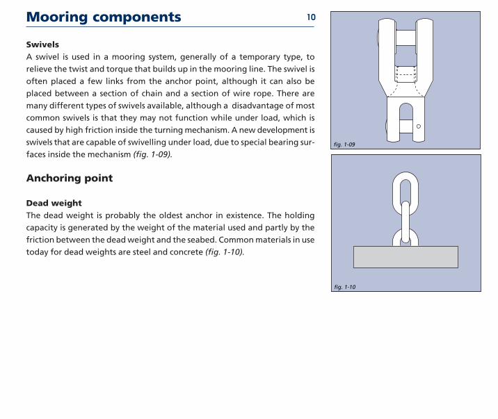
Mooring components
SwivelsA swivel is used in a mooring system generally of a temporary type to
relieve the twist and torque that builds up in the mooring line The swivel is
often placed a few links from the anchor point although it can also be
placed between a section of chain and a section of wire rope There are
many different types of swivels available although a disadvantage of most
common swivels is that they may not function while under load which is
caused by high friction inside the turning mechanism A new development is
swivels that are capable of swivelling under load due to special bearing sur-
faces inside the mechanism (fig 1-09)
Anchoring point
Dead weightThe dead weight is probably the oldest anchor in existence The holding
capacity is generated by the weight of the material used and partly by the
friction between the dead weight and the seabed Common materials in use
today for dead weights are steel and concrete (fig 1-10)
fig 1-10
13
fig 1-09
13
10
Mooring components
fig 1-12
13
Drag embedment anchorThis is the most popular type of anchoring point available today The drag
embedment anchor has been designed to penetrate into the seabed either
partly of fully The holding capacity of the drag embedment anchor is gen-
erated by the resistance of the soil in front of the anchor The drag embed-
ment anchor is very well suited for resisting large horizontal loads but not
for large vertical loads although there are some drag embedment anchors
available on the market today that can resist significant vertical loads
(fig 1-11)
PileThe pile is a hollow steel pipe that is installed into the seabed by means of a
piling hammer or vibrator The holding capacity of the pile is generated by
the friction of the soil along the pile and lateral soil resist-ance Generally
the pile has to be installed at great depth below seabed to obtain the
required holding capacity The pile is capable of resisting both horizontal
and vertical loads (fig 1-12)
fig 1-11
13
11
Mooring components
Suction anchorLike the pile the suction anchor is a hollow steel pipe although the diame-
ter of the pipe is much larger than that of the pile The suction anchor is
forced into the seabed by means of a pump connected to the top of the
pipe creating a pressure difference When pressure inside the pipe is lower
than outside the pipe is sucked into the seabed After installation the pump
is removed The holding capacity of the suction anchor is generated by the
friction of the soil along the suction anchor and lateral soil resistance The
suction anchor is capable of withstanding both horizontal and vertical loads
(fig 1-13)
Vertical load anchorA new development is the vertical load anchor (VLA) The vertical load
anchor is installed like a conventional drag embedment anchor but pene-
trates much deeper When the anchor mode is changed from the installa-
tion mode to the vertical (normal) loading mode the anchor can withstand
both horizontal and vertical loads (fig 1-14)
fig 1-13
13
fig 1-14
13
12
History of drag embedment anchorsHistory traces the use of anchors to China as far back as 2000 BC though it is quite probable that they
were used prior to this At that time the general tendency was to use large stones baskets of stones
bags of sand or even logs of wood loaded with lead which were then fastened to lines It was this
weight as well as a certain degree of friction on the bottom which secured a vessel in position
With the introduction of iron into anchor construction teeth or flukes were built on the anchor
allowing penetration into the seabed thus offering additional stability Yet these primitive
anchors were of poor construction and often broke under pressure Curved arms were intro-
duced in 1813 and from 1852 the so-called lsquoAdmiralty Anchorrsquo was used for ships of the Royal
Navy Another refinement in the 19th century was the elimination of the stock the crosspiece at
the top of an anchor which ensured that the positioning of the anchor would allow the flukes to
penetrate the soil A stockless anchor was invented in 1821 and became popular primarily as a
result of the ease of handling and stowing qualities still valued today
A large number of anchor types has been designed and commercialised over the years Some
have prospered others not The most recent designs are the results of vast experience and exten-
sive testing and are far more efficient than their historical predecessors A short overview of the
anchors in use today is presented on the following pages
History of embedment anchors 13
anchor shackle
shank
fluke
stabilisers
Based upon certain charateristics such as fluke area shank stabilisers it is
possible to classify the various anchor types To allow a rough comparison of
anchor type efficiency an indication () is provided for a 10 t anchor as (HOLDING
CAPACITY = WEIGHT EFFICIENCY)
Class A efficiency range 33 to 55
slender anchors with ultra-penetration
Characteristics of anchor types
StevprisClass A
Stevshark
FFTS
14
Class B efficiency range 17 to 25
anchors with lsquoelbowedrsquo shank allowing for improved penetration
Characteristics of anchor types
Bruce TS
Hook
Bruce SSClass B
15
Class C efficiency range 14 to 26
anchors with open crown hinge near the centre of gravity and relatively
short shank and stabilisers or built-in stabilisers
Characteristics of anchor types
Stevfix
Stevmud
Flipper Delta
StevinClass C
16
Class D efficiency range 8 to 15
anchors with hinge and stabilisers at the rear and relatively long shanks and
stabilisers
Characteristics of anchor types
LWT
Moorfast - Stato - Offdrill
Boss
DanforthClass D
17
Class E efficiency range 8 to 11
anchors with very short thick stabilisers hinge at the rear and a relatively
short more or less square-shaped shank
Characteristics of anchor types
Stokes
Snugstow
Weldhold
AC14Class E
18
Class F efficiency range 4 to 6
anchors with square shank no stock stabilisers The stabilising resistance is
built-in the crown
Characteristics of anchor types
Beyers
Union
Spek
US Navy StocklessClass F
19
Class G efficiency range lt6
anchors with small fluke area and stabilisers at the front of the shank
Characteristics of anchor types
Stock
Dredger
Mooring Anchor
Single Fluke StockClass G
20
History of vryhof anchor designs
A brief chronological summary of the types of anchors vryhof has designed
for use in the offshore and dredging industries
bull 1972 - The Stevin anchor The original design The wing was not yet
enlarged The anchor had a square shank It is no longer manufac-
tured
bull 1974 - The Hook anchor originally designed for permanent moorings
This design was surpassed in 1980 by the Stevpris design and is no
longer manufactured
bull 1977 - The Stevin Mk3 anchor is the improved version of the original
Stevin anchor It was equipped with an enlarged crown and fluke
area and a streamlined shank for more efficient penetration This
anchor is still manufactured and in use in offshore and dredging
activities It has all classification societies approvals
Stevin
Hook
Stevin Mk3
21
History of vryhof anchor designs
bull 1978 - The Stevfix anchor this anchor was designed with special fluke
points for harder soils and a larger fluke area than the Stevin but
has been surpassed by the Stevpris anchor It is no longer manufac-
tured
bull 1979 - The Stevmud anchor the Stevmud is essentially the Stevin anchor
with a considerably enlarged fluke area This anchor type was also
surpassed by the Stevpris anchor and is no longer manufactured
bull 1980 - The introduction of the Stevpris and Stevshark anchors The
Stevpris anchor is a deep penetrating anchor with a plough
shaped shank surpassing the performance of all earlier designs in
the vryhof range and incorporating the latest experience research
and knowledge of the anchor designer The Stevshark anchor is a
specially reinforced Stevpris anchor equipped with a serrated
shank and cutter-teeth for better penetration in hard soils such as
coral types or sandstone The fluke points are specially reinforced
to withstand high point loads
Stevmud
Stevpris
Stevfix22
History of vryhof anchor designs
bull1990 - The Stevpris Mk5 and Stevshark Mk5 were introduced The
improved versions of the original Stevpris and Stevshark anchors
Improvements have concentrated on two features higher holding
capacity and easier handling
bull1996 - Introduction of the Stevmanta VLA (Vertical Load Anchor) Based
on industry demand for an anchor that could withstand vertical
loads the Stevmanta VLA was developed The Stevmanta VLA is a
new design in which a traditionally rigid shank has been replaced
by a system of wires connected to a plate The anchor is designed to
accept vert ical (or normal) loads and is instal led as a
conventional drag embedment anchor with a horizontal load to
the mudline to obtain the deepest penetration possible By chang-
ing the point of pulling at the anchor vertical (or normal) loading
of the fluke is obtained thus mobilising the maximum possible soil
resistance As a VLA is deeply embedded and always loaded in a
direction normal to the fluke the load can be applied in any
direction Consequently the anchor is ideal for taut-leg mooring
systems
Stevshark Mk5
Stevmanta
23
Theory
2
TheoryAnchor design used to be based on practical experience of the anchor man-
ufacturer only Nowadays science has become a major factor in the design
process complementing the experience of the anchor manufacturer Based
on test results both in the laboratory and in the field a much better under-
standing of anchor behaviour has been achieved
The performance of an anchor is influenced by many different parameters
of which the following are only a few fluke area and design shank design
soil conditions load conditions type of mooring line
This chapter presents a short overview of how these parameters influence
the performance of the anchor It is by no means complete but it will give a
better understanding of how an optimal anchor design can be achieved In
the last part of this chapter a few relevant test results are presented
Introduction 25
Anchor holding capacity 26
fig 2-02
fig 2-01
fig 2-03
fig 2-04
Criteria for anchor holding capacityThe holding capacity of an anchor is governed by the following parameters
bull The fluke area which is limited by the strength of the anchor design
bullThe penetration of the anchor The penetration of the anchor is governedby the soil type (deep penetration in very soft clay and shallow penetra-
tion in sand) the anchor type (design) the type of mooring line that is
used (chain or wire rope) and the applied load
An increase in fluke area or an increase in the penetration depth of the
anchor results in a higher holding capacity
In the following paragraphs the influences on the anchor penetration are
further clarified
Streamlining of the anchorA streamlined anchor is very important for optimal penetration in the soil
As can be seen in fig 2-01 and fig 2-02 an anchor which has protruding
parts will encounter much more soil resistance and consequently will not
penetrate as deep as a more streamlined anchor with the same fluke area
Shank shapeA square shank which is common for most older type single shank anchors
will cause penetration resist-ance due to the fact that the soil can not pass
easily past the shank A clod of soil will form underneath the shank effec-
tively increasing the resistance of the soil (fig 2-03) Bevelling the shank
allows deeper penetrationWhen the single shank is replaced by a twin
shank construction (for instance Stevpris FFTS) usually two thin parallel
steel plates the soil can more easily pass through and past the shank and
consequently the twin shank anchor can penetrate deeper (fig 2-04)
Mooring lineAn anchor connected to a wire rope mooring line will penetrate deeper
than the same anchor connected to a chain mooring line (fig 2-05 and fig
2-06) This is caused by the higher lateral resistance (penetration resistance)
along the chain mooring line This effect is noticeable in all soil conditions
but especially in very soft clay where very deep penetration can be
obtained The holding capacity of a chain mooring line due to friction in
and on the seabed is larger than the holding capacity of a wire rope moor-
ing line
When an anchor reaches its ultimate holding capacity ie it will not resist
any higher loads at shallow penetration a wedge shaped piece of soil (in
front and above the anchor) will fail The holding capacity of the anchor can
then be described as a combination of the following parameters (fig 2-07
and fig 2-08)
bull The weight of the anchor (A)
bull The weight of the soil in the failure wedge (B)
bull The friction of the soil in the failure wedge along fracture lines (C)
bull Friction between fluke surface and soil (fluke area) (D)
bull The bearing capacity of shank and mooring line (E)
bull The friction of the mooring line in and on the soil (E)
Anchor holding capacity 27
fig 2-05
fig 2-06
fig 2-07
A
B
C
E
D
fig 2-08
Criteria for good anchor design
Anchor parameters can be scaled from geometrically proportional anchors
using the scale rules in table A
There are several attributes of an anchor which are crucial in assuring its
effective performance
bull The anchor must offer a high holding capacity a result of the fluke area
and shank design in combination with penetration and soil type
bull The design of the anchor should be such that the anchor is capable of
being used successfully in practically all soil conditions encountered over
the world ranging from very soft clay to sand corals and calcarenites
bull The flukeshank angle of the anchor should be easily adjustable allowing
the anchor to be quickly deployed in different soil conditions
bull The design must be so conceived and produced that the high loads com-
mon in practice can be resisted and that the anchor can be easily handled
installed retrieved and stored
bull The penetration of an anchor depends upon its shape and design
Obstructing parts on the anchor should be avoided as much as possible
bull The stability of an anchor encourages its penetration and consequently
its holding capacity Efficient stabilisers are an integral part of a good
anchor design
bull The shank must permit passage of the soil
bull The surface area of an anchor fluke is limited by the required structural
strength of the anchor
bull The anchor design must have optimal mechanical strength to fulfil
requirements and stipulations of the classification societies
bull The anchor should be designed to ensure an optimum between structur-
al strength of the anchor and holding capacity
bull The anchor should be streamlined for low penetration resistance
28
table A
Scale influence
Model Reality Related to Weight
Length L n W 13
Fluke area A n2 W 23
Weight W n3 W
Penetration P n W 13
Moment M n4 W 43
Moment of iner tia I n4 W 43
Section Modulus S n3 W
Bend ing stress MS n4n3=n W 13
Shear strength FA n3n2=n W 13
Aspects of soil in anchor design 29
Aspects of soil mechanics in anchor designUntil the nineteen seventies anchor design was largely an empirical process
There was not much science involved more use of experience It is not easy
for instance to calculate the Ultimate Holding Capacity (UHC) of an anchor
from the commonly known soil mechanics formulas The main problem is
the prediction of the volume of soil mobilised by the anchor To a large
degree it is this volume which determines the UHC Detailed understanding
of soil characteristics and behaviour is essential in the anchor design
process and of increasing benefit in handling at sea It is this understanding
which is the hallmark of a competent anchor designer and builder
For anchor design and installation the availability of good soil data is of
utmost importance as the soil is of great influence on anchor behaviour The
following are influenced by the soil conditions encountered
Anchor type - some anchors are more suited for soft soil conditions (soft
clay) while others are more suited for hard soils (sand and hard clays)
although there are a number of anchor types on the market that are suited
for most soil conditions encountered
Holding capacity - in hard soil like sand and hard clay the maximum
attainable ultimate holding capacity with a certain anchor type and size is
higher than the attainable ultimate holding capacity in very soft clay
Penetration and drag - in very soft clay the anchor will penetrate deeper
than in harder soil like sand As a consequence the drag length of the
anchor will also be longer in very soft clay than in hard soil
Retrieval forces - when an anchor is installed in very soft clay the required
retrieval forces will be higher than in hard soil like sand For example in
very soft clay the required retrieval force of an anchor can be equal to 80-
90 of the installation load while in hard soil (sand) the retrieval force
might only be 20-30 of the installation load
Soil classification 30 Undrained Shear Strength (kPa)
Consistency ASTM BSof Clay D-2488 CP-2004
Very soft 0 - 13 0 - 20
Soft 13 - 25 20 - 40
Firm 25 - 50 40 - 75
Stiff 50 - 100 75 - 150
Very stiff 100 - 200 150 - 300
Hard 200 - 400 300 - 600
Very hard gt 400 gt 600
table B
Soil strength is generally expressed in terms of the shear strength parame-
ters of the soil The soil type is classified mainly by grain size distribution
Grain size Soil descrip tionlt - 2 microm Clay2 - 6 microm Fine Silt6 - 20 microm Medium Silt
20 - 60 microm Coarse Silt60 - 200 microm Fine Sand200 - 600 microm Medium Sand06 - 2 mm Coarse Sand2 - 6 mm Fine Gravel6 - 20 mm Medium Gravel
20 - 60 mm Coarse Gravel60 - 200 mm Cobblesgt - 200 mm Boulders
IIn general the soil types encountered in anchor design are sand and clay
(Grain diameter from 01 microm to 2 mm) However mooring locations consist-
ing of soils with grain sizes above 2 mm such as gravel cobbles boulders
rock and such also occur Clay type soils are generally characterised by the
undrained shear strength the submerged unit weight the water content
and the plasticity parameters The consistency of clays is related to the
undrained shear strength However American (ASTM) and British (BS) stan-
dards do not use identical values (table B)
The undrained shear strength values Su can be derived in the laboratory
from unconfined unconsolidated tests (UU)
Soil classification 31
On site the values can be estimated from the results of the Standard
Penetration Test (SPT) or Cone Penetrometer Test (CPT) An approximate
relation between shear strength and the test values are shown in table C
The mechanical resistance of sandy soils is predominantly characterised by
the submerged unit weight and the angle of internal friction ϕ Theseparameters are established in the laboratory An approxim-ate correlation
between the angle ϕ and the relative density of fine to medium sand is given
in table D The undrained shear strength of clayey soil can also be estimated
based on manual tests
bull In soft clay the thumb will easily penetrate several inches indicating an
undrained shear strength smaller than 25 kPa
bull In firm (medium) clay the thumb will penetrate several inches with mod-
erate effort indicating an undrained shear strength between 25 kPa and
50 kPa
bull Stiff clay will be easily indented with the thumb but penetration will
require great effort indicating an undrained shear strength between 50
kPa and 100 kPa
bull Very stiff clay is easily indented with the thumbnail indicating an
undrained shear strength between 100 kPa and 200 kPa
bull Hard clay is indented with difficulty with the thumbnail indicating an
undrained shear strength larger than 200 kPa
The rock strength can generally be described by its compressive strength
(table E)
A classification system for soil based on the carbonate content and grain
size of the soil (Clark and Walker) is shown on the laste page of this chapter
Su UU SPT CPTkPa kPa N MPa
0 - 13 0 - 25 0 - 2 00 - 02
13 - 25 25 - 50 2 - 4 02 - 04
25 - 50 50 - 100 4 - 8 04 - 07
50 - 100 100 - 200 6 - 15 07 - 15
100 - 200 200 - 400 15 - 30 15 - 30
gt 200 gt 400 gt-30 gt30
table C
Descriptive Relative Angle SPT CPTterm Density ϕ N MPa
Very loose lt 015 lt 30 0- 4 0 - 5
Loose 015 - 035 30 - 32 4 - 10 5 - 10
Medi um dense 035 - 065 32 - 35 10 - 30 10 - 15
Dense 065 - 085 35 - 38 30 - 50 15 - 20
Very dense gt 085 gt 38 gt 50 gt 20
Descriptive term Compressivestrength qu [MPa]
Very weak lt 125
Weak 125 ndash 5
Moderately weak 5 ndash 125
Moderately strong 125 ndash 50
Strong 50 ndash 100
Very strong 100 ndash 200
Extremely strong gt 200
table D
table E
Flukeshank angle
The penetration of an anchor into a certain soil type is greatly influenced by
the selected flukeshank angle For hinging anchor types (Stevin Danforth
etc) the flukeshank angle is the angle between the anchor shackle the
hinge and the fluke tip The method for measuring the flukeshank angle
for fixed shank anchors (Stevpris FFTS etc) is not well defined Often it is
the angle between the anchor shackle the rear of the fluke and the fluke
tip but not all anchor manufacturers use the same definition
The recommended flukeshank angles for different soil conditions are pre-
sented in table F
Some modern anchors like the Stevpris Mk5 have an additional intermedi-
ate flukeshank angle of 41o which can be used in intermediate or more
complex soil conditions For instance at a location where the anchor has to
pass through a layer of soft clay before penetrating into a layer of sand
If an anchor is used with an incorrect flukeshank angle it will negatively
influence performance This is the case for all anchor types
In hard soil an anchor with a flukeshank angle of 320 will give the highest
holding power If an anchor is used with the flukeshank angle set at 500 the
anchor will fail to penetrate into the seabed and will begin to trip fall aside
and slide along the seabed (Fig 2-9 and 2-10)
32
fig 2-09
fig 2-10
Soil type Approximateflukeshank angle
Very soft clay 50˚
Medium clay 32˚
Hard clay and sand 32˚
table F
If an anchor is used in very soft clay (mud) with the flukeshank angle set at
32o the anchor will penetrate into the seabed however the penetration
will be less than when a flukeshank angle of 50o is used Consequently the
holding capacity will be lower when the flukeshank angle is set at 32o and
the drag length longer (Fig 2-11)
Flukeshank angle 33
fig 2-11
13
mud angle
sand angle
Because the fluke area of an anchor is of great influence on the holding
capacity it can be useful to compare the fluke area of different anchor
types that are available on the market today In general it can be stated
that two anchors of the same weight but of different type (for instance a
Stevin anchor and a Stevpris Mk5 anchor) do not necessarily have the same
fluke area Consequently two anchors of the same weight but different
type will have different holding capacities
Some examples
Fig 2-12 shows a Stevpris Mk5 anchor and a Moorfast anchor both of iden-
tical weight It demonstrates that in spite of being the same weight the
fluke areas differ substantially The ultimate holding capacity of the Stevpris
Mk5 anchor is 4 to 85 times higher than that of the same weight Moorfast
anchor
Fig 2-13 illustrates the difference in fluke area of the Stevpris Mk5 anchor
in comparison with the Bruce FFTS Mk4 anchor both of which have identi-
cal weight
Fluke area 34
fig 2-13
13
fig 2-12
13
Strength of an anchor design 35
Anchors should be designed to withstand the loads applied on them in the
different loading situations Typical loading situations and areas of special
attention for anchors are
bull During the proof loading of the anchors in the factory after construction
has been completed On basis of the proof load results the classification
societies issue the approval certificate
While embedded in the seabed
bull Depending on the soil conditions different loading situations can occur
on the anchor In sands and clays the load tends to be spread equally over
the anchor which generally presents no problems Retrieval is also very
simple without excessive loads placed on the anchor
bull In very hard soils the anchor has to be able to withstand the load with
only one or two of the fluke tips buried in the soil as penetration in very
hard soil conditions is generally shallow
bull In very soft clays (mud) penetration of the anchor is uncomplicated
However recovery of the anchor can cause high loads sometimes exceed-
ing the load that was used to install the anchor
bull Sidewards forces on the top of (shallow) buried anchors can be so
extreme that no anchor is capable of resisting them
During anchor handling
bull Care should be taken during the handling of the anchors as the loads
exerted by the winches vessels and chain can sometimes exceed the struc-
tural strength of the anchor and cause damage Anchor designers
attempt to design the anchors for these high loads however this is not
always possible due to variations in the magnitude of the loads during
handling operations
Strength of an anchor design 36
bull Large forces can be exerted on the anchor when high winch power is
used the anchor is caught on the anchor rack or caught behind the stern
roller of the AHV
bull The use of an improper anchorchaser combination When a chaser is used
that is either too small or too large the chaser could jam on the shank of
the anchor and cause damage
The strength of the Stevpris anchor is now more closely examined in the
light of the remarks made before
Strength of the shankThe prismatic shape of the Stevpris anchor not only ensures optimal pene-
tration of the soil but also guarantees maximum strength Although the
Stevpris design also has limitations it is one of the better designs to with-
stand sideward forces on the shank a frequent occurrence in practice
When using an anchor in very soft clay (mud) the bending moment on the
shank is low during the installation and when the anchor is in the soil
However during the breaking out of the anchor high bending moments
could be introduced in the shank due to the high retrieval forces required
in very soft clay In extremely sticky soils the breaking out force of the
anchor can rise to 80 or 90 of applied anchor load in certain instances
it can even exceed 100 To reduce these forces the breaking out proce-
dure is undertaken at low speed to allow time for the anchor to break out
Strength of an anchor design 37
Strength of the flukeThe strength of the fluke and especially the fluke points of an anchor are
very important when working in extremely hard soils such as coral lime-
stone and other rock types It is possible in such instances that the total
holding capacity of the anchor will have to be sustained by the fluke points
alone This means the structure must be strong enough to withstand
extreme bending forces Loading in normal soil conditions is not a problem
due to the fact that the load is equally spread over the fluke
In fig 2-14 the different force points are shown for varying soil conditions
The location on the fluke where the proofload is applied is also indicated
Strength in extremely hard soilsIn very hard soils such as calcarenite coral and limestone an anchor will not
penetrate very deeply Consequently the load applied to the anchor has to
be held by the fluke tips of the anchor and a small portion of the fluke This
means that extremely high loads will be applied to the fluke tips compared
to normal soil conditions such as sand and clay
For use in very hard soil conditions vryhof has designed the Stevshark
anchor a modified version of the Stevpris anchor To create the Stevshark
the Stevpris anchor has been strengthened consequently a Stevshark
anchor having the same outside dimensions and holding capacity as a
Stevpris anchor will be heavier
Strength calculations of the Stevshark design have been made to guarantee
sufficient strength in the fluke points The Stevshark anchor is designed to
withstand the application of the main part of the load on just its fluke tips
fig 2-14
rock
proofloadclay sand
Strength of an anchor design 38
To promote penetration the Stevshark anchor has a serrated shank and can
be provided with cutter points on the fluke tips Ballast weight can also be
added inside the hollow flukes of the anchor up to 35 of the anchor
weight This is important when working in very hard soil where the anchor
weight pressing on the fluke tips promotes penetration ie increased bear-
ing pressure
The loads in a mooring system are caused by the wind waves and current
acting on the floater Depending on the location of the floater in the world
different metocean conditions will prevail In the table below some
extreme metocean conditions are presented for different areas
The loads induced in the mooring system can be divided into quasi-static
loads and total dynamic loads The quasi static load is the load due to the
swell wind current and the frequency of the system For quasi-static loads
the systems tend to move at a low frequency generally with a period of 140
to 200 seconds
On top of this quasi-static load there are the individ-ual wave forces causing
a high frequency motion The high frequency motion causes dynamic shock
loads with a period of 10 to 14 seconds due to the rolling of the vessel and
the movements of the anchor lines through the water The quasi-static load
plus the individual wave forces is called the total dynamic load Generally
the quasi-static loads will be equal to 50 to 90 of the total dynamic load
See Fig 2-15 for an example of the difference between the quasi-static load
and the total dynamic load
Anchor loads and safety factors
fig 2-15
4000
3000
2000
1000
08300 8400 8500 8600 8700 8800 9800
389513Total dynamic
Quasi static13234213
13
Load
in k
N
Time in seconds
Location Waveheight Wave period Windspeed Currentm s ms ms
Campos Basin 8 ndash 10 12 - 15 25 1Gulf of Mexico 11 14 44 - 48 1Northern North Sea 15 - 16 15 - 17 38 - 39 09ndash 12
Porcupine Basin 16 - 18 16 - 20 39 - 41 10 ndash 15Vorine Basin 14 - 15 16 - 17 37 - 39 10 ndash 15West of Africa 4 - 6 10 - 16 20 03 ndash 06West of Shetlands 15 - 17 16 - 19 39 - 41 10 ndash 30
39
Anchor loads and safety factors
The quasi-static and total dynamic loads are generally calculated for the
intact and damaged load condition The intact load condition is the condi-
tion in which all the mooring lines are intact The damaged load condition
is the condition in which one of the mooring lines has broken
From the quasi-static load and the total dynamic load the required holding
capacity of the anchor can be calculated This is called the ultimate holding
capacity (UHC) for drag embedment anchors and the ultimate pull-out
capacity (UPC) for VLAs The required holding capacity is calculated by
applying the factors of safety specified by the classification societies
In the tables G and H the factors of safety are presented for the different
load conditions for drag embedment anchors (for instance the Stevpris Mk5
anchor) according to API RP 2SK The factors of safety used by the major
classification societies are generally similar to those given in API RP 2SK (2nd
edition 1996)
For VLAs the recently used factors of safety suggested by ABS are present-
ed in table I
The factors of safety for VLAs are higher than the factors of safety required
for drag embedment anchors due to the difference in failure mechanisms
When a drag embedment anchor reaches its ultimate holding capacity it
will continuously drag through the soil without generating additional hold-
ing capacity ie the load will stay equal to the UHC When a VLA exceeds its
ultimate pullout capacity it will slowly be pulled out of the soil
In table J the safety factors according to API RP 2SK for the mooring line are
presented for comparison purposes
40 Permanent Quasi-static Total dynamicmooring load load
Intact load condition 18 15
Damaged condition 12 10
Temporary Quasi-static Total dynamicmooring load load
Intact load condition 10 08
Damaged condition Not required Not required
VLA Total dynamicload
Intact load condition 20
Damaged condition 15
table G
table H
table I
Mooring line Quasi-static Dynamicsafety factors load load
Intact load condition 200 167
Damaged load condition 143 125
Transient load condition 118 105
table J
Drag embedment anchorsDrag embedment anchors are generally installed by applying a load equal to
the maximum intact load For permanent mooring systems the installation
load should be held for the period specified by the classification societies
(see table K) The anchor will then have penetrated to a certain depth but
will still be capable of further penetration because the ultimate holding
capacity has not been reached The anchor will also have travelled a certain
horizontal distance called the drag length After installation the anchor is
capable of resisting loads equal to the installation load without further pen-
etration and drag When the installation load is exceeded the anchor will
continue to penetrate and drag until the soil is capable of providing suffi-
cient resistance or the ultimate holding capacity has been reached However
there are certain effects which allow the anchor to withstand forces larger
than the installation load without further penetration and drag These are
The set-up and consolidation effectSet-up and consolidation mainly occur in clayey soils The penetrating
anchor disturbs the soil and the soil temporarily loses strength With time
the disturbed clay reconsolidates to its initial shear strength this takes from
a few hours up to 1 month depending on the soil type Because not all the
soil around the anchor is disturbed the set-up effect factor is less than the
sensitivity index indicates The disturbance mainly reduces the soil resis-
tance parallel to the fluke On reloading the parallel soil resistance gains
strength it takes a larger load to move the anchor again Equilibrium dic-
tates that also the normal load ie the bearing soil resistance to the fluke
increases consequently the load at the shackle increases also with the set-
up factor Observations on anchors for drilling rigs and theoretical consid-
erations for a 3 to 4 week consolidation time demonstrate a typical set-up
effect factor =15
Anchor behaviour in the soil 41 Classification Required duration ofsociety maintaining tension
Lloydrsquos Register of Shipping 20 minutes
American Bureau of Shipping 30 minutes
Det Norske Veritas (NMD) 15 minutes
table K
Anchor behaviour in the soil
The rate effect An increased rate of loading increases the soil resistance consequently the
anchor holding capacity increases This must be taken into account with
respect to total dynamic loads For anchor behaviour the rate effect factor
indicates how much higher the dynamic high frequency load may be with-
out causing extra movement of the anchor once installed at the installation
load The rate of loading influences pore pressure variations viscous inter-
granular forces and inertia forces Typical rate effect factors are 11 to 13
for total dynamic loads see Fig 2-16 where the rate effect is presented for
two different soil conditions (Su = 10 kPa and Su = 50 kPa)
Using the rate effect and set-up factors the behaviour of the anchor after
installation can be predicted more accurately
Vertical Load AnchorsA VLA is installed just like a conventional drag embedment anchor During
installation (pull-in mode) the load arrives at an angle of approximately 45
to 500 to the fluke After triggering the anchor to the normal load position
the load always arrives perpendicular to the fluke This change in load direc-
tion generates 25 to 3 times more holding capacity in relation to the instal-
lation load This means that once the required UPC of the VLA is known the
required installation load for the VLA is also known being 33 to 40 of
the required UPC
As a VLA is deeply embedded and always loaded in a direction normal to
the fluke the load can be applied in any direction Consequently the anchor
is ideal for taut-leg mooring systems where generally the angle between
mooring line and seabed varies from 25 to 450
42
fig 2-16
0
12
11
1
09
080 200 400 600 800 1000
Time factor St
Rat
e ef
fect
fac
tor
Su=10 kPa Su=50 kPa
Proof loads anchors
Proof loads for high holding power anchorsThe proof load according to Classification Societiesrsquo rules is applied at 13rd
of the fluke length and is carried out immediately on fabrication of the
anchor It is obtained by placing the anchor in a test yoke in which a
hydraulic cylinder applies the test loads controlled by a calibrated
manometer
(fig 2-17) The vryhof anchor types have been approved by the following
Classification Societies
bull The American Bureau of Shipping
bull Bureau Veritas
bull Det Norske Veritas
bull Germanischer Lloyd
bull Lloydrsquos Register of Shipping
bull Registro Italiano Navale
bull USSR Register of Shipping
bull Nippon Kaiji Kyokai
bull Norwegian Maritime Directorate
In the early days there were no specific regulations regarding the holding
power and strength of mooring anchors The rules which did exist were
often followed regardless of the type of vessel
Some anchors were approved as lsquohigh holding powerrsquo anchors This so-
called HHP approval was obtained after carrying out field tests in various
types of soil in which it had to be shown that an anchor provided a holding
power of at least twice that of a standard stockless anchor If an HHP anchor
was requested by the owner the anchor has proof tested in strict accor-
dance with the rules nothing more See table J for some examples of HHP
anchor proof loads A more detailed overview of HHP anchor proof loads is
fig 2-17
13
Anchor Proof Load Anchorweight fac tor weight
1 t 26 t 26 x
5 t 79 t 15 x
7 t 99 t 14 x
10 t 119 t 12 x
15 t 155 t 10 x
20 t 187 t 9 x
table J
43
Proof loads anchors
given in the product data section
The use of the specified proof loads for HHP anchors can lead to situations
where different types of anchors with the same holding capacity are proof
loaded at different loads see fig 2-18 From this figure it can be concluded
that the proof load of the anchors should preferably be related to the
break-load of the mooring line on the vessel
Nowadays the rules and regulations are far more rigid and the require-
ments have been substantially increased There are now special rules for
lsquomobile offshore unitsrsquo and lsquopermanently moored structuresrsquo
If anchors need mobile offshore units certification the following properties
may be required
bull Proof load of the anchors at 50 of the breaking load of the chain
bull Submission of a strength calculation of the anchor to the classification
society prior to commencing anchor production this includes determin-
ing the mechanical strength of the anchor as well as proving that the
applied material can withstand the proofload
bull A statement of documented holding power from the anchor supplier
bull Submittal of a Quality AssuranceQuality Control Manual
In fig 2-19 a mooring system is shown in which all of the components are
balanced The strength of the mooring line holding capacity of the anchor
and strength of the anchor are all in the correct proportion and comply with
the rules
44
fig 2-18
0 50 100 150 200 250
29 t Danforth
10 t Stevin Mk3
45 t Stevshark Mk5
4 t Stevpris Mk5
Proofload in t
Proofload HHP anchors UHC=250 t1313
fig 2-19
0 10 20 30 40 50 60 70 80 90 100
Breakload chain
Ultimate holdingcapacity anchor
Damaged load floater
Proofload chain
Pretensionload anchor
Intact load floater
Proofload anchor
Balanced mooring system API RP 2SK
Load in
Quality control 45
The application of more advanced and complex technology in anchor
construction has brought about requirements for a systematic approach to
quality Initiated by various authorities they are continuously refined and
followed up by operating companies such as vryhof anchor Like other
companies vryhof has become increasingly aware of the vital importance
of managerial aspects and their influence on the total quality-assurance
and control system
Design and fabrication of anchors for permanent moorings are in
accordance with the quality requirements of the Rules NSISO 9001 as
described in our Quality Assurance Manual Vryhof anchors obtained the
ISO 90012000 certificate No 29389-2008-AQ-NLD-RvA Rev1 issued by Det
Norske Veritas for lsquoDesign Manufacture of anchors and Sales of anchors
and mooring componentsrsquo
Quality control is maintained throughout production A compilation of
certificates is presented to a client upon completion of a project
Anchor tests
IntroductionIn addition to prac ti cal expe ri ence of users and asso ciates anchor tests are
one of the most reli able means of fore cast ing anchor per for mance and thus
mak ing a prop er choice of anchor type and size
Examining anchor tests that have been car ried out in the past cer tain
conclu sions can be made
bullMany tests were under tak en in which the results were record ed accu rate ly
bull Detailed reports how ev er have not been very com mon
bull Anchor tests of the past are not always easy to inter pret or com pare
because of dif fer ent soil and anchor types
bull Test results have not always been inter pret ed inde pen dent ly
bull The more tests results are strict ly com pared to prac ti cal results the bet ter
one can fore cast the hold ing power and gen er al beha vi our in prac tice
Vryhof is in the per fect sit u a tion of hav ing detailed test data avail able
togeth er with exten sive prac ti cal data obtained dur ing instal la tion and use
of anchors on pro jects on site
Research into anchor beha vi our and the ulti mate hold ing capac ity of
anchors is often car ried out by test ing a model anchor pref er ably fol lowed
by a full-scale test in the field The opti mal anchor test con sists of model tests
with 10 kg anchors fol lowed by full-scale tests with 1 t and 10 t anchors The
anchors should be pulled until the ulti mate hold ing capac ity is reached
It is obvi ous that full-scale test ing of anchors can be expen sive Large AHVs
strong winch es and strong moor ing lines are required which are not always
avail able For exam ple a 5 t Stevpris Mk5 anchor deployed in sand is
capable of stop ping a mod ern AHV at its full bol lard pull
46
Anchor tests 47
fig 2-20 Drag
Ho
ldin
g C
apac
ity A G B
C
D
E
F
Testing a 10 t Stevpris Mk5 anchor to its ulti mate hold ing capac ity in sand
would require a hor i zon tal pull ing capac ity of approx i mate ly 600 t
If anchor tests are to be com par able the test ing pro gram should pref er ably
meet as a min i mum the fol low ing cri te ria
bull An accu rate and sophis ti cat ed meas ur ing system should be used
bull The anchors should be test ed up to their ulti mate hold ing capac ity
bull Drag and pen e tra tion of the anchor should be record ed dur ing test ing
bull The anchor should be held under ten sion with a blocked winch for 15
min utes to inves ti gate any drop in hold ing capac ity
Reading test curvesThe beha vi our of an anchor dur ing ten sion ing can be accu rate ly inter pret ed
from the hold ing capac ity ver sus drag curve Sample test curves are pre sent ed
in Fig 2-20 Properly inter pret ed per for mance curves can explain a lot
about anchor beha vi our
bull Curve A is very steep and rep re sents a stream lined anchor in very stiff soil
bull Curve B is a nor mal curve for anchors in sand and medi um clay
bull Curve C is a curve of an unstable anchor This can be caused by a wrong
flukeshank angle set ting a short stab i lis er or a fluke that is too long
bull Curve D is a nor mal curve for an anchor in very soft clay
bull Curve E is an anchor with a 32o flukeshank angle in very soft clay
bull Curve F rep re sents an anchor that is turn ing con tin u ous ly This can be
caused by the absence of stab il is ers a too large flukeshank angle or a
low effi cien cy anchor at con tin u ous drag
bull Curve G rep re sents an anchor pen e trat ing in a layer of stiff clay over lain
by very soft clay
Anchor tests
Curves A B D E and G show a very stable ris ing line which indi cates that
the anchor builds up its hold ing capac ity con stant ly until the ulti mate hold ing
capac ity has been reached after which the anchor shows con tin u ous drag
The other curves are large ly self-explan a to ry
Test resultsVryhofrsquos exten sive data base of test results with dif fer ent anchor types sizes
and soil con di tions has been fre quent ly used in anchor design Data has
been obtained from prac tice scale mod els and from third par ties The data
has been inter pret ed and after wards incor po rat ed in the ulti mate hold ing
capac ity drag and pen e tra tion graphs of the Stevin Mk3 and Stevpris Mk5
anchor as well as in the ulti mate pull-out capac ity graph of the Stevmanta VLA
Norwegian Contractors (1984)In 1984 Norwegian Contractors car ried out tests at Digernessundet Stord
Norway The pur pose of these tests was to deter mine the cor rect anchor type
and size for the moor ing system of the Gullfaks A plat form dur ing the con struc -
tion of the plat form at Digernessundet Although the con struc tion would took
place at one loca tion it was known that three dif fer ent types of soil con di tions
would be encoun tered sand soft mud and an 8 m mud layer on rock After the
initial trials the Stevpris anchor was select ed for fur ther test ing
The 3 t Stevpris anchor that was used for the tests at a 330 pull ing angle
pro duced a max i mum hold ing capac ity of 150 t in the sand 102 t in the very soft
clay and 150 t in the layer of mud on rock As the moor ing system required
a sur vi val load of 1500 t a 65 t Stevpris (mud loca tion) 40 t Stevpris (sand
loca tion) and 60 t Stevshark (mud on rock loca tion) were select ed for the final
moor ing Fig 2-21 shows the test results of the 3 t Stevpris anchor while fig 2-22
shows the result of the ten sion ing of the final anchors with a load of 820 t
48
fig 2-21
150
100
50
250 10 20 30 40
Sand8 m soft clay 13on rock1313
Ho
ldin
g c
apac
ity
in t
soft clay1313
Drag in meters
fig 2-22
800
700
600
500
400
300
200
100
0
20 40 60 80
Full scale Gullfaks A anchors
Ho
ldin
g c
apac
ity
in t
Drag in meters
A B C
A = 40 t Stevpris in sand
B = 60 t Stevshark in mud on rock
C = 65 t Stevpris in mud
Survival load = 1500 ton
Final pretension load on site
Anchor tests 49
fig 2-23
700
600
500
400
300
200
100
0 50 100 150 200 250 300 350 400 450 500
Drag distance in feet
7-2
7-3
7-47-1
2-2
2-1
Large scale anchor test jip - 7 amp 2 t
Ho
rizo
nta
l lo
ad in
kip
s
Large scale anchor tests in the Gulf of MexicoIn 1990 tests were per formed with 2 t and 7 t Stevpris Mk5 anchors as part
of an anchor test Joint Industry Project (JIP) The anchors were test ed using
a wire rope fore run ner
The 2 t Stevpris anchor was test ed up to its ulti mate hold ing capac ity of 107 t
(235 kips) Due to insuf fi cient pull ing capac ity the 7 t Stevpris anchor could not
be pulled up to its ulti mate hold ing capac ity Based on the results of tests the
ulti mate hold ing capac ity of the 7 t Stevpris anchor was cal cu lat ed to be larg er
than 338 t (745 kips) (fig 2-23)
Anchor tests
UpliftStevpris anchors are well capable of resist ing uplift loads when they are deep -
ly embed ded Anchors in sand and firm to hard clays do not pen e trate very
deeply and only take small uplift loads Stevpris anchors installed in very soft
clay and mud pen e trate deeply a typ i cal pen e tra tion for a 15 t anchor is 15 to
25 meters Due to the inverse cat en ary in the soil the anchor line arrives at the
anchor shack le at an angle of 20o to 30o with the mud line Once the anchor is
installed a load mak ing an angle up to 20o with the hor i zon tal at mud line will
not change the load ing direc tion at the anchor A Stevpris anchor has been
test ed in the Gulf of Mexico with grad u al ly increas ing pull angle (fig 2-24)
The max i mum resis tance was obtained for 18o uplift at mud line
50
fig 2-24
13
35 000
30 000
25 000
20 000
15 000
10 000
5 000
0
60
50
40
30
20
10
0
0 50 100 150 200 250 300
= dyn load13= pull angle
Lin
e an
gle
vs
mu
din
e
Line length pulled in feet
Lin
e lo
ad in
lbs
18˚13
Cyclic effect fac torThe load ing at the anchor is cyclic Exxon per formed cyclic tests on anchors
report ed by Dunnavent and Kwan 1993 Although the max i mum cyclic load
was less than the initial instal la tion load the stat ic load applied after the
cycling phase revealed 25 to 50 larg er anchor resis tance than the initial
instal la tion load (fig 2-25) This effect is explained by fur ther pen e tra tion
of the anchor Applying this knowl edge to the anchors the stat ic anchor
resis tance after some storm load ing improves by the cyclic effect fac tor of
125 to 15
Anchor tests 51
fig 2-25
015
01
000 50 100 150 200 250 300 350
Time in seconds
An
cho
r re
sist
ance
in k
N
Initial static capacity
Cycling
Increased capacity13vs initial static
Anchor tests 52
fig 2-26
200
150
100
50
0
0 5 10 15 20 25 30 35
13
Line length pulled in feet
Block winch
13Change mode13
13
Lin
e lo
ad in
13900 pulling 13angle with 13seabed in 13normal 13loading 13mode
Tests with Stevmanta anchorsTests have been per formed in the Gulf of Mexico and offshore Brazil The
Stevmanta anchor being pulled in with a load equal to F accept ed a ver ti cal
load to the anchor of up to 2 times F Amongst the many tests the anchor
relax a tion was meas ured The anchor with a fluke area of 013 m2 was
pulled in at 0o pull angle (fig 2-26) then load ed ver ti cal ly to a load equal to
16 times the max i mum instal la tion load At this load the winch was
blocked
Anchor tests 53
fig 2-27
200
150
100
50
0
2000 2200 0 00 2 00 4 00 6 00 8 00
Time in hours
Lin
e lo
ad in
13Change from 13pull-in to normal mode 1313
13Block winch 1313
13900 pulling 13angle with 13seabed in 13normal 13loading 13mode
This per mit ted the mon i tor ing of the load with time (fig 2-27) as what
would be expect ed in real cir cum stanc es at a con stant load ed anchor line
The results show that the hold ing capac ity of the anchor does not change
sig nif i cant ly dur ing con tin u ous load ing as the observed decrease in ten sion
was due to move ment of the winch The sub se quent pull ing at 700 AM
showed that for only a small move ment the full plate capac ity (2 x instal la -
tion load) could be reached Continuous pull ing caused the anchor to loose
resis tance and break out
Anchor tests
To dem on strate that the fea ture of these anchors is not only a ver ti cal resis -
tance the anchor was installed with a hor i zon tal pull the mode changed to
the nor mal (ver ti cal) mode and the anchor sub se quent ly pulled with an
uplift angle of 30o (fig 2-28) The beha vi our is sim i lar to the ear li er ver ti cal
pull test However for the 30o pull angle the anchor did not break out but
moved slow ly along the pull ing direc tion through the soil The graphs clear -
ly show this effect and that the anchor can be used for sub stan tial hor i zon -
tal loads
54
fig 2-28
13
200
150
100
50
0
0 5 10 15 20 25 30 35 40
Line length pulled in feet
13Change from 13pull-in to normal mode 1313
Lin
e lo
ad in
13300 pulling 13angle with 13seabed in 13normal 13loading 13mode
Soil table
Increasing lithification
Increasing grain size of
particulate deposits
000
2 mm
006
3 mm
2 mm
60 m
m
Carbonate silt
Carbonate sand
Carbonate grave
l
Carbonate clay
Silic
eous ca
rbonate
Silic
eous ca
rbonate
silt
sand
Mixed
carbo
nate and
non-carbonate gravel
Calca
reous clay
Calca
reous silic
a silt
Calca
reous silic
a sand
Clay
Silic
a silt
Silic
a sand
Silic
a grave
l
Calcilutite
Calcisiltite (carb
Calca
renite (carb
Calciru
dite (carb
(carb Calysto
ne)
Siltstone)
Sandstone)
Conglom Or Breccia
Conglomeratic
Claye
y ca
lcilu
tute
Silic
eous ca
lcisiltite
Silic
eous ca
lcaren
ite
calcirudite
Calca
reous
Calcareao
us clay
stone
Calca
reous siltstone
Calca
reous sandstone
conglomerate
Conglomerate or
Claysto
ne
Siltstone
Sandstone
breccia
Fine-grained
lim
esto
ne
Detrital lim
esto
ne
Conglomerat
limesto
ne
Fine-grained
Fine-grained
silice
ous
Silic
eous detrital
Conglomerate
agrilla
ceous lim
estone
limesto
ne
limesto
ne
limesto
ne
Calca
reous
Calcareous clay
stone
Calca
reous siltstone
Calca
reous sandstone
conglomerate
Conglomerate of
Claysto
ne
Siltstone
Sandstone
Breccia
Crystallin
e lim
esto
ne or marble
Conve
ntional m
etam
orp
hic nomen
clature applie
s in this sec
tion
Approx Rock Very weak Weak to moderately weak Moderately strong to strong Strong to extemelystrength strong
Cementation of Very weak to firmly Well cemented soil (well cemented)soil cemented soil rock
Total carbonate content
90 50 10 90 50 10 90 50 10 50
55
Practice
3
PracticeAlthough theoretical knowledge of anchors is essential for good anchor design
and selection the practical issues are just as important The handling of an
anchor and the selection and use of support equipment is of equal importance
Anchor handling is a critically important and often complicated process It is
influenced by such factors as the weight and shape of the anchor the nature
of the soil the depth of the water the weather conditions the available
handling equipment and the type and weight of mooring line It is for these
reasons that anchor handling is a subject which requires careful considera-
tion Without proper anchor handling optimal performance of an anchor is
not possible
In the process of handling anchors various types of support equipment are
necessary or beneficial An anchor manual would be incomplete without
consideration of these auxiliary items the reasons for their use their oper-
ation and the advantages and drawbacks involved
This chapter gives an overview of the recommended procedures that should
be followed for anchor handling and the types and use of the support
equipment during the handling operations The following handling
procedures are by no means complete but they do give some suggestions
which can be applied to each anchor handling procedure and adapted for
specific circumstances and locations
Some of the topics covered in this chapter are
requirements for a soil survey connection of the anchor to the mooring
line chasers handling the Stevpris anchor handling the Stevmanta anchor
the Stevtensioner anchor handlingsupply vessels
Introduction 57
Soil survey 58Typical contents survey report
bull Cone pen e tra tion resis tance
bull Sleeve fric tion
bull Pore pres sure
bull SPT val ues
bull Gra nu lom e try and per cent age fines
bull Wet and dry den sities
bull Water con tent
bull Drained and undrained tri ax al tests
bull Undrained shear strength also remould ed
bull Uncon fined com pres sion tests
bull Plas tic ity lim its
bull Spe cif ic grav ity
bull CaCO3 con tent
bull Shell grad ing
bull Angu lar ity and poros ity
bull Com press ibil ity
bull Cemen ta tion
bull Nor mal ised rock hard ness test (point load test)
bull RQD index rock qual ity des ig na tion
table K
For the dimen sion ing of drag embed ment anchors the avail abil ity of site-spe -
cif ic soil data is impor tant For advice on spec i fy ing drag embed ment anchor
typesize and cal cu lat ing expect ed beha vi our the site-spe cif ic soil data should
be com pared with soil data of pre vi ous drag embed ment anchor (test) sites
The soil sur vey require ment for the design of drag embed ment anchors usu al ly
con sists of only shal low bore holes while in anchor pile design deep bore holes
are required For suc tion anchor design therefore a more exten sive soil
inves ti ga tion is generally required when com pared to drag embed ment anchors
When choos ing between anchor pile suc tion anchor and drag embed ment
anchor the finan cial impli ca tions of the soil sur vey should be taken into account
A typ i cal soil sur vey for drag embed ment anchor design requires a sur vey
depth of twice the length of the fluke in sand and 8 times the fluke length
in very soft clay In most cases a depth of 8 to 10 meters is suf fi cient
although in very soft clay a recon nais sance depth of 20 to 30 meters should
be con sid ered For opti mal drag embed ment anchor dimen sion ing each
anchor loca tion should ideal ly be sur veyed The soil inves ti ga tion can con -
sist of bore holes vib ro cores cone pen e tra tion tests or a com bi na tion of
these Cone pen e tra tion tests includ ing sleeve fric tion are pre ferred but
they should be accom pa nied by at least one vib ro core or sam ple bore hole
per site to obtain a descrip tion of the soil Depending upon the type of sur -
vey per formed and the soil con di tions encoun tered the sur vey report
should present the test results obtained on site and in the labor a to ry includ -
ing the points as shown in table K
It is pos sible to dimen sion the drag embed ment anchors based on lim it ed
soil infor ma tion (for instance fewer bore holes) The lsquolackrsquo of soil data can be
com pen sat ed by choos ing a con ser va tive (larger) anchor size
Pile or anchor 59
The choice between piles and anchors is only pos sible for per ma nent
systems Piles are not a good invest ment when an anchored entity must be
moved But the choice is often made for piles on emo tion al grounds a pile
does not drag However anchors that are prop er ly pre-ten sioned on site
will also not drag
While it is a psy cho log i cal ly load ed sub ject expe ri ence has shown that the
choice between anchor and pile is mere ly a mat ter of eco nom ics The
required pile weight for a system is equal to the required weight of a
Stevpris anchor Piles cost about 40 of equiv a lent capa bil ity anchors
However the instal la tion costs for piles are much high er Piles require a fol -
low er and a pile ham mer The instal la tion spread for piles is much more sig -
nif i cant a crane barge with sup port spread ver sus the two anchor han dling
ves sels The weath er downtime for a spread involv ing a crane ves sel is much
long er than when AHVs are used To allow drag of the anchors dur ing pre -
ten sion ing extra chain length is required Sometimes the pre ten sion load
for piles is much less than for anchors The sur vey work for anchors is gen er -
al ly much sim pler than for piles When aban don ing a field anchor remov al
is much cheap er than remov al of installed piles The choice between piles
and anchors strong ly depends upon the cir cum stanc es The table L can help
in esti mat ing the costs for the two alter na tives
Suction piles are an alternative for drag embedment anchors and piles also
for MODU applications The advantage is the accurate positioning of the
suction piles The disadvantage is the cost of the pile itself and the cost of
the installation
Description Pile Suction Anchorpile
Soil survey - - +
Procurement + - -
Installation spread - - +
Installation time - - +
Pile hammer - + +
Follower - + +
Pump unit + - +
Pretensioning + - -
Extra chain + + -
Rest value pileanchor - + +
Removal of anchor point - + +
ROV + - +
+ less expensive - more expensive
table L
Mounting instructions Stevpris Stevshark Mk5
A1pin 1 pin 2
pin 3 pin 4B1 B2
A2
13
Forward fluke-shank connectionRemove the locking plates A1 and A2 which are tack-welded to the fluke
Aft fluke-shank connectionMove the pins 1 and 2 to the outer side Remove the split pins and open
the locking plates B1 and B2 Move the pins 3 and 4 to the outside
60
Plate A1 amp A2
Pin 1 amp 2
Plate B1 amp B2 Pin
3 amp 4
Fit the rear shank lugs into the fluke by means of a crane Manoeuvre the
rear shank lugs with the notch into the gap in the flukes as indicated in
the figures When in position rotate the shank forward to align the front
pins with the shank
AttentionMake sure the serial number of the shank corresponds with the serial num-
ber of the fluke for reason of identification and certification
Align pins 1 and 2 with the forward shank eyes Move pins 1 and 2 back into
position Place the shank in the sand middle or mud position Align pins 3
and 4 with the rear shank lugs Move pins 3 and 4 back into position Fit and
weld the locking
plates A1 and A2
on the fluke See
welding detai l
below Close the
locking plates B1
and B2 and secure
with split pins
Vryhof recommended welding procedure for locking plates A1 and A2Fillet weld with electrode accAWSE7018
Welding process SMAW electrode
welding position 2F
material S355J2G3 (St52-2N)
preheat material 50deg C
interpass temp max 250deg C
Mounting instructions Stevpris Stevshark Mk5
13
Serial number
Sand angle Middle angle Mud angle
Locking plate
61
Mud
Middle
Sand
Notch
Mounting instructions Stevspris Mk6
13
A1pin 1 pin 2
pin 3 pin 4
A2
13
Plate A1 amp A2
Pin 1 amp 2
Forward fluke-shank connectionRemove the locking plates A1 and A2 which are tack-welded to the fluke
Aft fluke-shank connectionMove the pins 1 and 2 to the inner side Remove the splitpins and nuts
from pins 3 and 4 and move the pins 3 and 4 to the outside
62
1 2 3 4
Fit the rear shank lugs into the fluke by means of a crane Manoeuvre the
rear shank lugs into the gap in the flukes as indicated in the figures When
in position rotate the shank forward to align the front pins with the
shank
AttentionMake sure the serial number of the shank corresponds with the serial num-
ber of the fluke for reason of identification and certification
Align pins 1 and 2 with the forward shank eyes Move pins 1 and 2 back into
position Place the shank in the sand middle or mud position Align pins 3
and 4 with the rear shank lugs and insert them in the lugs Tighten the bolts
and insert splitpins 3 and 4 Fit and weld the locking plates A1 and A2 on the
fluke See welding detail below
Vryhof recommended welding procedure for locking plates A1and A2Fillet weld with electrode accAWSE7018
Welding process SMAW electrode
welding position 2F
material S355J2G3 (St52-2N)
preheat material 50deg C
interpass temp max 250deg C
Mounting instructions Stevspris Mk6
13
Sand angle Middle angle Mud angle
Mud eye
13
Mid eye
Sand eye
Locking plate
63
Setting the flukeshank angle
Introduction
In soil such as sand and medium to hard clay an anchor with a flukeshank
angle of 32o will give the highest holding power An anchor with a 50o
flukeshank angle in this soil will not penetrate but will drag along the
seabed If used in mud a 50o flukeshank angle is appropriate An anchor with
a 32 o flukeshank angle will penetrate less and generate lower holding
capacity in mud(fig 3-01)
The Stevpris Mk5 anchor has an additional flukeshank angle setting of 41o
which can be adopted in certain layered soil conditions (table M)
Changing the flukeshank angle on the Stevpris Mk3
This can be carried out within half an hour with the Stevpris anchor upside
down on deck
Secure the anchor on deck Connect a tugger wire (C) to the holes (D) on the
bottom side of the fluke Change from mud to sand angle by removing the
locking plates and the two rear pins in (B) decrease the flukeshank angle
by hauling the cable (C) Reinstall the pins and locking plates in (A) Seal
weld the lock-ing plates do not weld them to the pins (fig 3-02)
64
fig 3-01
no penetration
D
fluke angle too large in hard soil
change from mud to sand angle
fig 3-02
Soil type Optimalflukeshankangle setting
Very soft clay (mud) 500
Certain layered soils 410
Medium to hard clay
or sand 320
Stevpris Mk5 only
table M
Setting the flukeshank angle 65
Change from sand to the mud position increase angle by veering (C) change
over pin and locking plates from (A) to (B) No special welding requirements
(fig 3-03)
Changing the flukeshank angle on the Stevpris Mk5 Changing the
flukeshank angle on the Stevpris Mk5 anchor is even quicker No welding
required Veering and hauling (C) to change the flukeshank angle as
above the pin however remains in (A) the locking plate is secured by means
of a cotter pin (fig 3-04)
change from sand to mud angle
fig 3-03
change flukeshank angle Stevpris Mk5
fig 3-04
Connecting a swivel to the Stevpris anchorTo connect a swivel to the Stevpris anchor several different configurations
are possible These are
Type I - The swivel is connected directly to the shank of the anchor thus
omitting the anchor shackle (fig 3-05)
J swivel shackle C end link B enlarged link A common link
Type II - The swivel is connected to the anchor shackle (fig 3-06)
J swivel shackle C end link B enlarged link A common link
Type III - The swivel is connected to the anchor shackle via a special design
end link
(fig 3-07)
K special end link J swivel C end link B enlarged link A com-
mon link
Type IV - The swivel is part of a forerunner connected to the anchor shack-
le for instance the forerunners VA02 VA04 and VA 06 described
in the product data section (fig 3-08)
PL pear link A common link B enlarged link H swivel
When a chaser is used in combination with the Stevpris and swivel some of
the configurations mentioned above are more suitable than others In gen-
eral swivels are only designed to withstand longitudinal forces and are
usually not designed for use in combination with chasers The design of the
chaser tends to stop it at the swivel Consequently there will be high
bending forces on the swivel which can result in damage or even breakage
Connecting a swivel 66
J C B A
fig 3-05
fig 3-06
J C B A
fig 3-07
K J C B A
fig 3-08
P L A B H B A
Generally it is best when the swivel is fitted some distance from the anchor
when a chaser is used The chaser can then pass the swivel and stop on the
anchor shank When a load is applied to the chaser the swivel is only loaded
longitudinally This means that in combination with the use of a chaser the
configuration type III and type IV are preferred
When the swivel (or swivel forerunner) is connected to the anchor shackle
by means of an end shackle and a chaser is used the end shackle and the
anchor shackle should be connected bow through bow instead of pin
through bow as is normal practice This to minimise the chance of damage
to the shackles
The illustrations fig 3-09 through fig 3-14 show how and how not to
connect the swivel to the Stevpris anchor when using a chaser
(See next page for fig 3-13 and 3-14)
Connecting a swivel 67 damage possible
fig 3-09
NO
fig 3-10
damage possible
fig 3-11
fig 3-12
NO
Connecting a swivel
The best method for chasing with a swivel in the system is to maintain the
tension of the anchor line as much as possible during chasing This will make
the chaser pass more easily over the swivel
68 damage possible
fig 3-13
fig 3-14
NO
Chasers 69
Chasers and their applicationTo facilitate handling pendant wires may be applied to retrieve the anchor
These wires are connected to a pendant eye situated on the anchor and
equipped with a buoy for picking up In deeper water higher anchor
break-out forces are encountered resulting in longer heavier pendant
wires and consequently larger buoys Due to wear caused by the continuous
movement of the buoy by the waves these pendants will break close to the
buoy The buoys would then float free and the anchors are much more
difficult to recover
To overcome this chasers were introduced These were rings lsquochasedrsquo along
the cable towards the anchor and back again to a rig or handling vessel
Their function was to ensure both installation and break-out of the anchor
without having to use a pendant linebuoy The chaser system thus totally
eliminates buoys partly eliminates cables and reduces wear on the system
The cost of a chaser is small when compared to the cost of a mooring line It
is therefore extremely important from an operatorrsquos viewpoint that chasers
do not inflict damage to the mooring lines
Chasers 70
Towing a chaser along mooring lines with at times high interface
pressures must result in wear It is thus essential that such wear is taken by
the chaser and not the mooring line The chasers vryhof recommends are
manufactured in a material that is softer than the steel used for the
mooring line Chaser wear is induced by the application of high interface
pressure between the mooring line and the chaser High interface pressure
can arise from
bull Pulling the chaser along a slack mooring line
bull Maintaining high tension in the chaser workwire when chasing a
tensioned mooring line
Chasing operations are best carried out on mooring lines which are fully
tensioned There is little need for the application of high interface pressure
while chasing the permanent chaser is captive on the mooring line and
unlike the J-chaser will not become disengaged due to a slack work wire
For optimum chasing operations the length of the chaser pendant line
should be at least 15 times the waterdepth
There are many different types of chaser available on the market today
A selection of the different chaser types is described in more detail on the
following pages
Chaser types 71
fig 3-16
fig 3-15
The J-chaserThe J-chaser (fig 3-15) is used on mooring lines where the anchor has to be
recovered and no permanent chaser has been installed or the normal
recovery mechanism has failed In other cases the J-chaser is used simply to
keep a chain free from a pipeline during deployment of the anchors The
chaser is deployed over the stern roller of an AHV at approximately 13 of
the water depth The chaser is towed across the mooring catenary until it
catches the chain It is then towed into contact with the anchor shankfluke
for anchor break-out and retrieval
The permanent chain chaserAs a practical alternative to the buoy and pendant the permanent chain
chaser (fig 3-16) was introduced Originally simple shackles were used
these were followed by special cast oval rings which were attached to a pen-
dant by a lsquobightrsquo of chain and shackle Very soon afterwards the pear-shaped
chaser with shackle eye was introduced The design of these chasers offers
superior sliding and penetration properties
Chaser types 72
fig 3-18
The detachable chain chaserFor rigs in service it is sometimes preferred to equip the mooring with a
chaser which does not require the anchor chain to be broken and re-made
Detachable chain chasers (fig 3-17) were introduced to satisfy this need
The withdrawal and replacement of the single bolt permits easy assembly of
the chaser on the mooring cable
The permanent wire chaserThe permanent wire chaser (fig 3-18) was introduced when rigs moved to
deeper waters and composite wirechain mooring systems became neces-
sary The chaser incorporates a lsquorockerrsquo which is centrally mounted on a
hinge bolt The rocker has two opposing grooves and when the chaser is
engaged with the mooring line the wire slides through one of these
grooves irrespective of the angle which the chaser makes with the mooring
The large radius at the base of the groove assists in reducing wear of the
rocker and avoids severe lsquoopeningrsquo of the lay of the wire if a loop of wire is
pulled during the handling process The material of the rocker is not as hard
as the material of the wire This means that wear is taken by the rocker
without damage to the wire and because the rocker is easily removable
replacement is relatively inexpensive The permanent wire chaser is easily
detachable by removal and re-assembly of the hinge bolt and rocker
Some designs of wire chaser incorporate fully rotating rollers over which
the mooring wire passes To be effective such rollers need to be of a large
diameter and require to be supported by bearings They are consequently
larger heavier and much more costly than the permanent wire chasers dis-
cussed above and because of their size they require more power at the
AHV to penetrate the seabed and reach the anchor
fig 3-17
Chaser types 73
fig 3-19
The J-lock chaserThe J-lock chaser (fig 3-19) has been designed so that it can slide along the
chain in one direction and when the pulling direction is reversed the chas-
er locks on the chain and does not slide any further This means that the
tension in the mooring line can be wholly transferred from the rig to the
chaser The J-shape permits catching the anchor chain after the anchor has
been installed This means that this chaser can be used to assist in unforeseen
circumstances The well-balanced and lsquoguidingrsquo design of the chaser enables
catching the chain when the chaser approaches a mooring at a point where
the catenary angle is as high as 450
When a normal permanent chaser is used under unforeseen conditions
there is the chance that the AHV cannot break out the anchor by means of
the chaser The J-lock chaser can help in such an instance It is released from
a second AHV and slides along the chain towards the anchor The design
prevents the J-lock chaser from sliding back The J-lock chaser is stopped at
the permanent chaser If the winch pull of both tugs is now increased the
J-lock chaser prevents the permanent chaser from sliding away from the
anchor Consequently the forces required do not increase and the anchor
can easily be broken out After this operation the J-lock chaser can be released
again
This chaser can also be used when a very heavy chain has to be installed It
assists during installation by lifting the chain
Stevpris installation 74
fig 3-20
chaser
fig 3-21
always deck anchor with chain between flukes
D
fig 3-22
quickly pass drum
D
fig 3-23
triangular plates on drum
D
Stevpris deployment for MODUs
IntroductionTypical methods for deployment and retrieval of Stevpris anchors with an
anchor handling vessel (AHV) are described focusing on the use of chasers
for handling the anchor (fig 3-20) This is the most common practice on
mobile drilling rigs (MODUs) Handling using permanent pendant lines is
similar
Deployment procedures for the Stevpris anchor will also be given for
permanent moorings where chasers are normally not used
Laying anchorsIt is preferred and by some operators required to deck the anchor before
run out to check the jewellery Run the anchor line out the full distance with
anchor on deck or on roller with the chain between the flukes (fig 3-21)
Boat increases power until anchor line tension rises on rig winch tension
meter When rig gives order to lower the anchor veer pendant till anchor
arrives at roller Allow the anchor some speed to negotiate the bump at the
change-over from the deck on to the roller (fig 3-22)
If anchor is kept on roller keep triangular plates below the main shackle on
the drum for stability of the anchor Alternatively the chaser can be kept on
deckroller In this situation the propeller thrust passes underneath the
anchor and does not influence the fluke (fig 3-23)
Stevpris installation 75
fig 3-24
STOP
fig 3-25
fig 3-26
wait for signal rig
D
Reduce propulsion momentarily when anchor passes the propeller thrust
keep chaser on anchor head for control of anchor orientation and lower
anchor (fig 3-24)
Once below the propeller wash zone reactivate and maintain propeller
thrust to well above 30 tons Keep constant tension in order to ensure
anchor does not fall through chaser ie anchor remains in the chaser and
orientation of the anchor is correct (fig 3-25)
Note In some circumstances AHVs prefer to run the anchor hanging from
the pendant line below the propeller wash approximately 60 to 80 meter
above the seabed This method requires less power on the winch during the
actual laying of the anchor If this method is employed make sure that at all
times the anchor is correctly oriented in the chaser Keep constant tension
in the pendant line to prevent the anchor from falling through the chaser and
possibly turn
Stop lowering when anchor hangs 10 to 15 meter above the bottom and
advise rig Rig now instructs AHV to pay out until pendant line is 14 to 15
times the water depth in shallow water (100m) and 13 to 14 times in deep-
er water AHV increases power till tension is again seen to rise at the rig ie
the load in the line is larger than the chain-soil friction (fig 3-26)
Rig commences to pull in slowly AHV further increases power until tension
rises further at rig winch At this moment rig orders AHV to lay the anchor
AHV immediately stops the propulsion and is consequently pulled back-
wards AHV pays out pendant and maintains paying out pendant after anchor
has landed on the bottom till a wire length of 15 to 2 times the water depth
is out Enough slack wire must be paid out not to disturb the anchor during
buoying off or waiting Stay above or behind the anchor
Stevpris installation 76
fig 3-30
patience in very soft soils
D
fig 3-27
rig hauls AHV slacks
D
fig 3-28
do not pull after landing
D
fig 3-29
wrong keep cable 13under tension
D
Rig continues heaving the cable to a sufficient load equal to the total
chainsoil friction plus 50 t to embed the anchor fully and create confidence
in good setting
This also gives stability to the anchor when the AHV strips the chaser back
or buoys off the pendant Now the AHV can retrieve the chaser and return
to the rig If circumstances allow the rig can tension up to the full preten-
sion load directly (fig 3-27)
No extra pull after landing
It is customary with older anchors such as Danforth Moorfast etc to give
another pull once the anchor is on bottom Do not do this with Stevpris
anchors Once the anchor hits bottom AHV should not pull again Pendant
line must remain slack otherwise anchor could land upside down
(fig 3-28) Suggestion pre-load the anchors to the maximum required
pretension load as soon as the chaser is 100 meter or more ahead of the
anchor ie do not wait If anchor has not been laid correctly a rerun can be
made immediately
Retrieving anchorsThe chaser should be brought to the anchor with a pendant of at least the
length of 15 to 2 times the water depth measured from the stern roller
Chaser should hang freely down from the anchor line till the bottom is
reached ie slack in the pendant line A too short pendant andor too little
tension in the cable results in a situation as sketched (fig 3-29)
While chasing the rig should maintain tension of 60 to 70 of the pre-load
tension No tension in pendant to ensure smooth passing over the chain
When chaser is pulled into contact with anchor shank increase thrust and
keep thrust while heaving especially in rough water (fig 3-30)
Stevpris installation 77
fig 3-31
keep13pullingrig13
hauls
D
fig 3-32
always deck anchor with chain between flukes
D
fig 3-33
keep tension
D
fig 3-34
wrong anchor cannot deck
D
The motion of the vessel itself now helps gradually to break the anchor
loose Sequentially with the vessels motion the pendant is shortened
gradually Anchors in very soft clay can be buried very deep Have patience
take your time and be gentle with the equipment the anchor will come
The rig can help and speed-up the operation by hauling the anchor line at
the same time Once the anchor is off bottom keep the chaser in contact
with the bow shackle by maintaining sufficient thrust (fig 3-31)
Anchor orientationThe anchor flukes are always oriented towards the rig on deck the anchor
lays on its back with shackle towards AHVs bow and cable between the
upwards directed fluke points Check jewelry (fig 3-32)
It is important to control the anchor orientation at all times for easy racking
laying and decking of the anchor ie keep pendant line under tension
while working the anchor If the anchor slides through the chaser the
anchor has to be pulled back to the stern roller and orientation checked
(fig 3-33)
Decking the Stevpris anchorIf anchor is not correctly oriented reduce propulsion and let anchor slide
down through the chaser Rotation is easier while near the rig where all
loads are lower (fig 3-34)
Stevpris installation 78
fig 3-35 turn
fig 3-36
fig 3-37
stop reduce 13propulsion
D
STOP
Turn the anchor with a shot of propeller wash Then pay out pendant make
sure anchor is below the propeller wash away from the propeller influence
zone (fig 3-35)
Increase propulsion moving AHV forward pulling chaser in contact with the
anchor Make sure the stern roller is perpendicular to the chain the chain
directing between the fluke points (fig 3-36)
With sufficient bollard pull haul pendant stopreduce thrust for only a few
seconds when anchor passes the propeller wash onto the drum Pull anchor
on the drum allow the anchor to turn with its back on the roller fluke
points up Then pull further on deck (fig 3-37)
Stevpris installation 79
With little tension in the line the chain hangs steep against the fluke points
and anchor cannot rotate easily (A) Before rotating the anchor pull on the
cable the anchor will be free to turn (B) and (C) (fig 3-38)
With anchor on the stern roller reactivate propulsion For inspection anchor
can be pulled on deck If required change fluke angle to 32 degrees for
hard soil or to 50 degrees for very soft soil Mind every anchor type will be
unstable and drag in hard soil stiff clay or sand with a fluke angle set for
mud (fig 3-39)
fig 3-38
fig 3-39
Stevpris installation 80
What not to doThe anchor is approaching the drum If the AHV maintains thrust the water
flow will push the fluke (fig 3-40)
If the propeller is not stopped the thrust risks turning the anchor around
the cable then acting as a shaft (fig 3-41)
The relative weight of the anchor increased by the thrust force on the fluke
will cause the anchor and the cable to slide down through the chaser and
control of anchor orientation is lost (fig 3-42)
When the thrust is maintained while hauling in the chaser the cable
prevents the anchor to turn on its back at the stern roller Boarding will be
difficult now The anchor could pass the stern roller on its side and get dam-
aged
So stopreduce the thrust just before the anchor passes the propeller wash
(fig 3-43)
fig 3-40
thrust on anchor makes it swing
fig 3-41
and rotate
fig 3-42
anchor slides through chaser
fig 3-43
damage
Stevpris installation 81
Racking the StevprisRig heaves in anchor line pulling AHV towards it AHV keeps sufficient ten-
sion in pendant chaser remains in tight contact with anchor anchor
remains correctly oriented (fig 3-44)
At some distance from the rig AHV pays out winch wire while keeping suf-
ficient bollard pull (at least 15 times anchor weight) to keep chaser on
anchor head Anchor flukes point towards the rig Rig hauls AHV veers
while keeping some tension in the pendant line transferring the anchor to
the bolster The direction of the anchor cable must now be perpendicular to
the rack (fig 3-45)
When anchor arrives at bolster reduce tension to 15 tons As soon as anchor
is resting on bolsters slack pendant wire completely If tension is not suffi-
cient anchor falls out of control of the chaser and might rotate and make
racking difficult If this occurs bring anchor to the stern of the AHV rotate
anchor with fluke points directing outwards and keep chaser tight on the
anchor (fig 3-46)
Deploying Stevpris from the anchor rack AHV receives pendant from rig and connects to AHV winch wire AHV
moves to a position at a good distance but less than the water depth (for
instance 50 meter dependent on weather) from the rig Stop winch and
keep sufficient tension 20 to 30 tons or more as required to maintain the
chaser on the head of the anchor Only now rig pays out cable while AHV
hauls in on the winch The AHV maintains sufficient tension while pulling
the anchor to the stern roller Reduce the power of the propeller as anchor
passes the wash zone and bring anchor on roller for inspection and reacti-
vate thrust (fig 3-47)
fig 3-44
keep tension
D
fig 3-45
keep tension
D
fig 3-46
wrong 13risk losing control 13over anchor orientation
fig 3-47
keep tension
D
Stevpris installation 82
Boarding the anchor in deep waterIn deep water the weight of the anchor line becomes of predominant
importance For line loads larger than 8 times the anchor weight the anchor
could be pulled against the chaser as illustrated it could even position itself
upside down In such cases boarding the anchor is difficult and damage
might occur (fig 3-48)
The best and preferred solution is to pull the anchor from the bottom and
have the rig haul the anchor line allowing the boarding of the anchor near
the rig where loads are smaller
If this is not possible or allowed for some reason another solution is to
reduce the weight that is hanging from the anchor This can be done by
lifting the anchor line using a lock chaser or grapnel handled by a second
vessel (fig 3-49)
It is recommended to board the anchor with the chain between the fluke
The anchor fluke is generally designed to withstand loads up to 8 times the
anchor weight (fig 3-50)
It happens that the anchor is accidentally pulled over the roller on its side
Due to the large forces damage to shank and fluke might occur when the
chain is hanging over the anchor (fig 3-51)
fig 3-48
anchor weighthigh tension
fig 3-49
lock chaser
fig 3-50
8 x anchor weight
fig 3-51
large weight
Stevpris installation 83
fig 3-52
fig 3-53
with ballast in fluke use chain forerunner
D
chain
wire
If boarding the anchor on its side is inevitable make sure that before
boarding the vessel is turned to free the anchor line from the anchor and
haul gently The chain will pass the stern roller next to the anchor However
this situation should be avoided as damage may occur (fig 3-52)
Ballast in flukeUsing a wire rope forerunner and ballast material placed inside the hollow
fluke the anchor may not topple over with the fluke points directed
downwards A wire anchor line might be too light to position the anchor
correctly and the anchor may not topple over the anchor could skid over
the seabed and prevent penetration
When the fluke is ballasted the weight of a chain forerunner will cause the
shackle to nose down and bring the fluke in penetration position (fig 3-53)
Stevpris installation 84
Chaser equilibriumTo control the anchor the chaser collar must always be on the anchor head
The tension in the anchor cable must be equal or larger than 15 times the
weight of the anchor If not the anchor slides through the chaser and the
orientation is not controlled (fig 3-54)
Equilibrium forces determine if chaser is in contact with the anchor Near
bottom the vertical load at the chaser from the anchor line Flv is small
The chaser remains only in contact with the anchor if the bollard pull Fph is
larger than the horizontal line load Flh which in turn must be larger than
the anchor weight W (if not the anchor will slide down) The angle of the
pendant line must be larger than 45deg (fig 3-55)
Recommendation Bollard pull must always be equal or larger than the line
tension ie use a minimum bollard pull of 20 to 30 tons for a 12 to 15 ton
anchor Use a minimum pendant line length of 14 to 15 times the water
depth in shallow water (100m) and 13 to 14 times the depth in deeper
water (fig 3-56)
fig 3-54
pendant line force
anchor line tension
anchor weight
fig 3-55
Fp
Fph
Fpv
Flh
FlFlv
W
fig 3-56
chaser
Deployment for permanent moorings
The simplest deployment procedure for the Stevpris anchor is to lower the
anchor to the seabed using the mooring line When the anchor is nearly on
the seabed the AHV should start moving slowly forward to ensure that the
anchor lands correctly on the seabed (fig 3-57)
Another option for the deployment of the Stevpris anchor is to connect a
temporary installation bridle (wire rope) to the anchor The bridle is
connected to the padeyes situated at the back of the shank of the anchor
The AHV then lowers the anchor overboard while paying out the mooring
line and the bridle simultaneously (fig 3-58)
To recover a Stevpris anchor after it has been installed the AHV should take
the mooring line and pull it in the opposite direction that the anchor was
installed in generally away from the centre of the mooring The AHV
should recover the mooring line till a length of approximately 15 times the
water depth is still overboard
When only 15 times the water depth of mooring line is left overboard the
AHV should block the winch and keep a constant tension on the mooring
line equal to the pre-load tension Once the anchor starts to move in the
soil a lower tension in the mooring line can be used (fig 3-59)
Stevpris installation 85
fig 3-57
fig 3-58
mooring line
temporary bridle
fig 3-59
Piggy-backing
IntroductionPiggy-back is the practice of using two or more anchors in order to obtain
holding power greater than can be achieved with one only Piggy-backing
is used when anchors are employed with insufficient holding capacity
This can be caused by improper design for the particular environment or
insufficient anchor size
In some soil conditions the use of two smaller anchors in piggy-back can
offer an advantage over the use of one larger anchor This can be the case
when the anchor has to hold in a certain layer and holding capacity in the
underlying layer is uncertain
Considerations to remember on piggy-backing
bullInstalling a piggy-back system is more costly than the installation of a sin-
gle anchor
bullIf the mooring line of the second anchor is connected to the rear of the
first anchor the stability penetration and holding capacity of the first
anchor may be less than is the case for a single anchor The force from the
second anchor may tend to pull the fluke of the first anchor closed (hing-
ing type anchors)
bullIf the piggy-back anchor is connected to the first anchor by means of a
chaser the chaser may obstruct penetration of the first anchor
bull Both anchors must be exactly in line with the mooring line load The lead
anchor may become unstable if a lateral load is applied
bullTwo hinging anchors in piggy-back do not provide 2 times but only 1 to 16
times the individual holding capacity of the two anchors for reasons
described in second point above
86
Piggy-back methods 87
fig 3-60
bullIf the first anchor is not influenced by the pull from the second anchor and
the second anchor (fixed flukeshank type anchors) is connected at 3 to 4
shank lengths distance from the first anchor the holding capacity of the 2
anchors may be up to 25 times the holding capacity of the individual
anchors due to the extra penetration of the second anchor
Piggy-backing involving hinging anchorsSince there is little difference between handling one hinging anchor or two
the first method is described with a Stevin anchor (hinging) in combination
with a Stevpris anchor (non-hinging) Here the Stevpris is main anchor and
the Stevin is back-up This is the best solution when using a fixed shank
anchor as the fluke of the Stevpris anchor can not be pulled closed The pendant
line is connected to the padeye near the anchor shackle so performance is
not reduced Note if the piggy-back anchor can not be laid in line with the
mooring load the piggy-back anchor makes the main anchor unstable In
such a case the Stevpris can better be placed as the second anchor
For optimal performance of the combination the pendant line between
the two anchors should be wire rope to promote penetration and obtain
better holding capacity (fig 3-60)
Piggy-back methods
The installation procedure is described as follows
bull Pay out the main anchor as usual
bull Tension the mooring line until the anchor slips
bull Connect the second anchor to the pendant line
bull Bring the anchor to its location
bull Lower the piggy-back anchor and tension the mooring line again
bull Provide the pendant of the second anchor with a buoy for easy retrieval
Piggy-backing with two Stevpris anchorsWhen two Stevpris anchors are used in piggy-back the holding capacity of
the combination may be equal or higher than the sum of the individual
holding capacities of the anchors The installation procedure of two
Stevpris anchors in piggy-back is as follows
bull Pay out the main Stevpris anchor with the mooring line connected to the
anchor shackle and the pendant line (wire rope for optimal performance
and approximately three times the shank length of the first Stevpris
anchor) connected to the padeye behind the anchor shackle
bull Connect the other end of the pendant line to the anchor shackle of the
second Stevpris anchor (fig 3-62)
bull To lower the second Stevpris anchor to the seabed a second pendant line
is connected to the padeye behind the anchor shackle
bull Using the second pendant line the Stevpris anchors are lowered to the
seabed and positioned and buoyed off
bull The Stevpris anchors are then tensioned by pulling on the mooring line
(fig 3-61)
88
fig 3-62
Piggy-back methods 89
fig 3-63
fig 3-61
Piggy-backing by using a chaserSometimes chasers are used to connect the piggy-back anchor to the first
anchor (fig 3-63) although a pendant line connected directly to the padeye
behind the main anchor shackle of the first anchor is prefered
The installation procedure described for two Stevpris anchors is also applic-
able when a chaser is used for the connection
During the deployment of the piggy-back combination care must be taken
that anchors are installed in line with the load
Stevmanta VLA installation
IntroductionThe Stevmanta VLA consists of an anchor fluke which is connected with
wires to the angle adjuster The angle adjuster is responsible for changing
the anchor from the installation mode to the vertical (or normal) loading
mode
There are many options to install VLA anchors The most efficient methods
are based on two different principles
bull Double line installation method using the fixed angle adjuster
bull Single line installation method using the shear pin angle adjuster
The double line installation method is typically used when it is preferable
to install the anchor with a steel wire rope installation line instead of using
the actual mooring line (for example polyester)
The following three typical methods for installing the Stevmanta VLA are
discussed
bull Single line installation method
bull Double line installation method
bull Double line installation method using the Stevtensioner
It is also possible to use the Stevtensioner with the single line installation
method however because this is very similar to the double line installation
method with Stevtensioner it is not presented here
90
fig 3-64
installation mode
shear pin
fig 3-65
normal mode
Single line installation procedureThis procedure requires only one AHV for installation of the Stevmanta The
Stevmanta is deployed with the shearpin angle adjuster The mode of the
anchor changes when the shearpin breaks at a load equal to the required
installation load When the shear pin breaks the Stevmanta changes from
the installation mode to the normal (vertical) loading mode (fig 3-64 and
fig 3-65)
Installation procedureIn the installation procedure an optional tail has been included on the
Stevmanta The tail assists in orientation of the Stevmanta on the seabed
Connect the installationmooring line to the angle adjuster on the
Stevmanta on the AHV Lower the Stevmanta overboard The Stevmanta
will decend tail first ie the tail will be the first part to reach the seabed (fig
3-66)
When the Stevmanta is on the seabed an ROV can optionally inspect the
anchor (position and orientation) The AHV starts paying out the installa-
tion mooring line while slowly sailing away from the Stevmanta (fig 3-67)
Stevmanta VLA installation 91
fig 3-66
tail for13orientation13
recovery
fig 3-67
ROV