Embed Size (px)
Citation preview
The Imaging Magnetograph eXperiment for the SUNRISE balloon Antarctica project
Martínez Pillet*, V., Bonet, J.A., Collados, M., Jochum, L., Mathew, S., Medina Trujillo, J.L., Ruiz
Cobo, B. Instituto de Astrofísica de Canarias, c/ Vía Láctea s/n, La Laguna, E38200, Spain
del Toro Iniesta, J.C., López Jiménez, A.C., Castillo Lorenzo, J., Herranz, M., Jerónimo, J.M.,
Mellado, P., Morales, R., Rodríguez, J. Instituto de Astrofísica de Andalucía (CSIC), P.O. Box 3004, Granada, E18080, Spain
Álvarez-Herrero, A., Belenguer, T., Heredero, R.L., Menéndez, M., Ramos, G., Reina, M., Pastor,
C., Sánchez, A., Villanueva, J. Instituto Nacional de Técnica Aeroespacial, Torrejón de Ardoz, Madrid, E28850, Spain
Domingo,V., Gasent, J.L., Rodríguez, P.
Grupo de Astronomía y Ciencias del Espacio, Univ. Valencia, Paterna, Valencia, E46980, Spain
ABSTRACT The SUNRISE balloon project is a high-resolution mission to study solar magnetic fields able to resolve the critical scale of 100 km in the solar photosphere, or about one photon mean free path. The Imaging Magnetograph eXperiment (IMaX) is one of the three instruments that will fly in the balloon and will receive light from the 1m aperture telescope of the mission. IMaX should take advantage of the 15 days of uninterrupted solar observations and the exceptional resolution to help clarifying our understanding of the small-scale magnetic concentrations that pervade the solar surface. For this, IMaX should act as a diffraction limited imager able to carry out spectroscopic analysis with resolutions in the 50.000-100.000 range and capable to perform polarization measurements. The solutions adopted by the project to achieve all these three demanding goals are explained in this article. They include the use of Liquid Crystal Variable Retarders for the polarization modulation, one LiNbO3 etalon in double pass and two modern CCD detectors that allow for the application of phase diversity techniques by slightly changing the focus of one of the CCDs. Keywords: Polarimetry, Fabry-Perot etalons, magnetographs, balloon borne telescopes, Sun
1. INTRODUCTION Recent observations of the photosphere of the Sun with a resolution of 100 km have revealed what seem to be the building blocks of sunspot penumbrae1. Fundamental to this achievement was the use of a 1m aperture telescope able to obtain near diffraction limited imaging. These observations correspond to imaging in relatively wide bands (10 Å wide) that allow very fast exposure times (about ten milliseconds) with the help of adaptive optics (AO) and, in some cases, postprocessing techniques. But the diagnostic capability of this wide band imaging is very limited. In-depth diagnostic analysis requires the use of spectroscopic and polarimetric techniques. Resolving a spectral line with tens of mÅ and polarimetric techniques reduce the number of photons to dramatic low levels and the exposure times are increased typically to several seconds. Maintaining diffraction limited performance during these longer exposure times is much more demanding on AO systems. State of the art current systems are able to reach diffraction limited performance for 1m size apertures only occasionally while, most of the time, they only improve the final image quality without reaching the desired diffraction limited quality. The only way to secure stable imaging conditions for the periods of time needed *[email protected]; Telephone +34-922-605237
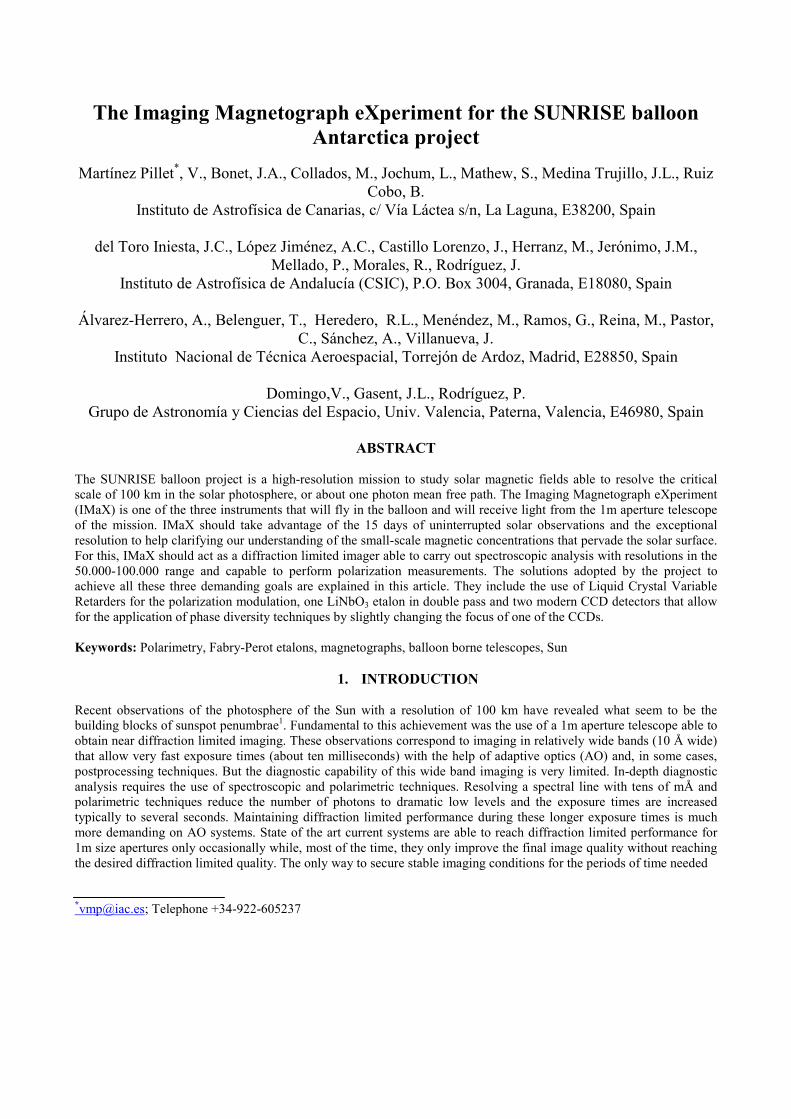
to track solar magnetic fields, from their origin to their eventual disappearance, is from space. The Japanese-led Solar-B (launch in 2006) mission will be a major breakthrough in this direction and will combine magnetic field measurements at high resolution (telescope 0.5mt diameter) with imaging in X-ray and EUV spectroscopy for the study of the hot Solar Corona in X-ray and EUV spectroscopy for the study of the hot Solar Corona and its link with the photospheric magnetic fields. The SUNRISE mission2 is a step in the same direction but with emphasis on even higher spatial resolution (1mt telescope) and UV near-UV spectroscopy and imaging for the study of the chromosphere and transition region. The Imaging Magnetograph eXperiment (IMaX) is a vector magnetograph that will fly with the SUNRISE balloon in Antarctica integrated with other instruments near the end of 2007 (within the NASA Long Duration Balloon program). The one meter telescope3 provides a solar image at F2 that is shared at different wavelengths by the three instruments and by the Correlation tracking and Wavefront sensor instrument4 (CWS) on the instrument platform. The CWS is in charge of stabilizing the image at the focus position of all three instruments to the demanding level of 0.005 arcsec rms in order not to degrade image quality due to the motions of the gondola at fly altitude. IMaX receives the light from a system of light distribution (Image Stabilization and Light Distribution, ISLiD) that includes the tip-tilt mirror and two beamsplitters that select the spectral region of interest for IMaX and sends the light to the entrance IMaX focus position at F4. The portion of the ISLiD relevant to IMaX is shown in Fig. 1. The image plane at F4 is a telecentric image with an F# of 25 and a scale of 8.25 arcsec/mm. This contribution describes the instrument concept for IMaX starting from the F4 image plane and explains the different solutions adopted in its definition.
Figure 1: Optical path of the SUNRISE light distributions system (ISLiD) that feeds IMaX at F4 with a stabilized beam. The two beamsplitters feeding IMaX (one acting as a camera mirror) are shown. IMaX is being developed by a Spanish consortium of 4 institutions: the Instituto de Astrofísica de Canarias (IAC, La Laguna), the Instituto de Astrofísica de Andalucía (IAA, Granada), the Instituto de Técnica Aeroespacial (INTA, Madrid) and the Grupo de Astronomia y Ciencias del Espacio (GACE, University of Valencia). IAC is the PI institution that provides the scientific concept of the instrument, manages the project and handles system engineering and software development of the user interface. IAC also participates in the development and calibration of the LCVRs and etalon subsystems. IAA is in charge of the detector subsystems, data handling and compression and, in general, of electrical subsystems of IMaX. The optical, optomechanical and thermal part of IMaX is being developed by INTA. The assembling, integration and verification of IMaX at system level will be done in the INTA facilities. Finally, GACE provides the structural components for the optomechanical subsystem and for the pressurized enclosures including the main and the proximity electronics of the instrument. IMaX PDR is scheduled for October 2004 and its delivery to the SUNRISE PI institution (MPS, Lindau) will take place in December 2005.
2. SCIENCE REQUIREMENTS AND INSTRUMENT CONCEPT SUNRISE (and IMaX as part of the whole experiment) will study the smallest magnetic scales ever resolved on the solar surface, with the aim of helping to answer key questions like: What are the origin and the properties of the intermittent magnetic structure (flux tube concentrations and more diffuse components)? How is the magnetic field

brought up and removed from the solar surface? IMaX, among all the instruments aboard SUNRISE, will provide the highest temporal resolution (the vector magnetic field will be determined every few tens of seconds) over the whole field of view. This high temporal cadence is needed to study phenomena occurring on the Sun at very short temporal scales (for instance, the formation of kG flux tubes) and the propagation of MHD waves. Also important is the fact that the Sun will be uninterruptedly observed during 12-15 days, under conditions that are far more stable than at the ground. Only after studying these long observational sequences, the natural temporal scales of magnetic field appearance and disappearance will become clear.
Figure 2: Optical and optomechanical concept of IMaX. The light enters in the bottom right mechanical mount with a circular aperture where the prefilter, LCVRs and collimating optics are included (this subsystem is temperature controlled to ± 0.5 degrees). The light is then directed to the LiNbO3 double pass system chamber (controlled to ± 0.05 degrees). Exiting this etalon chamber the beam is folded by a flat mirror and sent to the camera-cube beamsplitter (acting as a linear polarizer) mechanical mount. The light then reaches the two (pressurized) CCD detectors. The CCD parallel to the etalon has a mechanism to include in the optical beam a phase diversity plate for occasional monitoring of the optical performance of the instrument and subsequent correction of residual aberrations. The entrance to the pressurized etalon chamber has two subapertures that also include optical components to perform the collimating re-imaging task. Proximity electronics and harness are not included. The optical bench is in vacuum. To fulfill its role, the science requirements of IMaX are:
• IMaX as a polarimeter: IMaX must be able to measure the 4 Stokes parameters of a Zeeman sensitive solar spectral line (Fe I 5250.6 Å with a Landé factor of 1.5) and provide a S/N of at least 103 (this translates into a sensitivity of 10 G for longitudinal magnetic fields and 100 G for transverse magnetic fields). Vector (I,Q,U,V) and longitudinal (I,V) observing modes must be available.
• IMaX as a spectrometer: IMaX should provide a spectral resolution better than 100 mÅ (current baseline is somewhere between 50-60 mÅ). Modes observing 4 points within the spectral line and a nearby continuum and modes observing only two spectral points (providing faster cadence) must be available.
• IMaX as a diffraction limited imager: IMaX must be diffraction limited (Strehl ratio > 0.8) for a perfect incoming image at the input focal plane.
• All observing modes must be carried out in less than 30 seconds, with some modes (longitudinal magnetograph with only two wavelength points) providing faster cadences of only 5 seconds.
• IMaX should be able to cope with residual image motion at the level of 1 pixel (0.05 arcsec) by using a dual beam polarimeter configuration5.
These top-level science requirements make IMaX a complex instrument to work in autonomous mode for 15 days or so. Still, one of the drivers during the definition of the instrument has been to produce an instrument as simple as possible able to comply with the requirements. In Figure 2, we show the current IMaX optical and optomechanical concept that is explained in some length in the rest of the paper.
3. THE INSTRUMENT AS A POLARIMETER
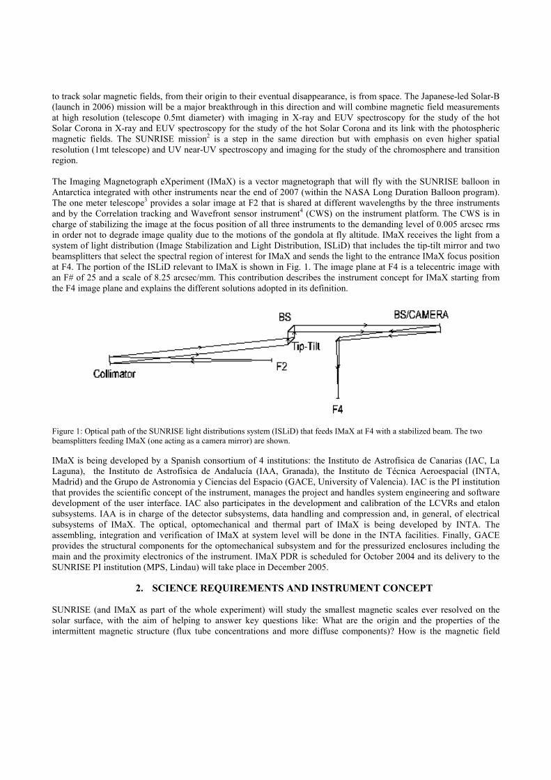
IMaX will modulate the polarization signals using liquid crystal variable retarders (LCVRs). LCVRs are interesting because they require no mechanical motion to produce the desired effect. 2 LCVRs based on nematic liquid crystal material (produced by TECDIS Display Ibérica in collaboration with the IAC6) are able to produce the modulation schemes needed for the vectorial and longitudinal observing modes. Modulation schemes using two LCVRs have been extensively studied in the past7. A very flexible configuration uses one LCVR with its fast axis at 0o (i.e. aligned with the final linear polarizer) and retardance ρ (depending on the input voltage V) and a second LCVR with the fast axis at 45o and retardance σ. The IMaX beamsplitter makes the linear polarization analysis. In this configuration the detected intensity is a linear combination of the Stokes parameters:
ρρσσ
ρρ
σσ
ρσρσσ
sin,cossin,cos
====
−++=
scsc
VcsUssQcII D
LCVR ρ LCVR σ Linear Polarizer This configuration allows easily arranging both vectorial and longitudinal observing modes. For the vector mode, we look for four independent linear combinations [I1, I2, I3, I4] (accumulation states) where all four Stokes parameters are equally weighted. By equating the coefficients that multiply the Stokes parameters one finds that the retardance values needed are ρ=[45,135,225,315] and σ=[54.736,125.264,234.736,305.264]. Using these angles the coefficients multiplying the Stokes parameters in equation (1) are all equal to ±1/√3. The order in which these voltages are applied may have an impact in the switching times of the LCVRs. As large jumps increasing the retardance (decreasing voltage) correspond to long LCVRs switching times, their use should be avoided. We propose to use the following ordering of retardance values that uses only small jumps to increase retardances:
[ρ1, ρ2, ρ3, ρ4]=[315,315,225,225] [σ1, σ2, σ3, σ4]=[305.264, 54.736, 125.264, 234.736],
resulting in four accumulation states (I1, I2, I3, I4) able to provide all four Stokes parameters as
(1)
(2)
VUQII
VUQII
VUQII
VUQII
31
31
31
31
31
31
31
31
31
31
31
31
4
3
2
1
−+−=
+−−=
−−+=
+++=
4321
4321
4321
4321
43
43
43
43
43
43
43
43
43
43
43
43
41
41
41
41
IIIIV
IIIIU
IIIIQ
IIIII
−+−=
+−−=
−−+=
+++=
Using this vector modulation scheme the so-called polarization modulation efficiencies8 attain their maximum values:
[εI, εQ, εU, εV]=[1, 3
1 ,3
1 ,3
1 ]=[1.,0.577,0.577,0.577]
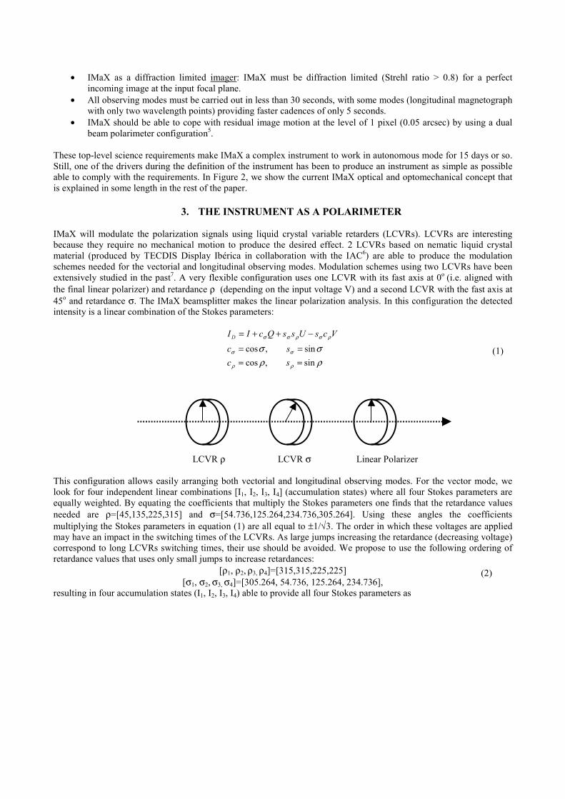
In practice, these efficiencies will only be achieved if the switching times were infinitely small and the applied voltages exactly correspond to the retardances given above. Finite switching times and voltage-retardance misscalibrations will decrease the efficiencies. Extensive laboratory measurements at IAC with the TECDIS-IAC LCVRs have shown, however, that all possible orderings of retardances in (2) show modulation efficiencies that are very insensitive to the actual ordering and with values that are always larger than 0.5, only slightly smaller than the optimum 0.577. If we use an LCVR from TECDIS with a 6 µm gap and liquid crystal of type ZLI-3449-100 (see Figure 3), the voltages needed for the retardances of equation (2) are (in volts):
[V(ρ1), V(ρ2),V( ρ3),V(ρ4)]=[2.444,2.444,3.101,3.101] [V(σ1), V(σ2),V(σ3), V(σ4)]=[2.510,7.630,4.234,3.017]
These voltages will be produced with an electronics that has a 5 mV resolution and an error of ±3 mV. Given the typical calibration curve of an LCVR, these voltage errors produce, in the end, calibration matrices that differ from the expected ones (equation 3) by only a few 10-3.
Figure 3: calibration of one of the LCVRs from TECDIS showing the voltages and retardances values for the longitudinal and vectorial modes (ρ values in solid line; σ values in dotted lines). For the longitudinal mode, the situation becomes simpler. Inspection of equation (1) shows that by zeroing the effect of the first LCVR (i.e. setting ρ to 0o) and making a quarter wave plate of the second LCVR (i.e. setting σ to 90o or to 270o) only the Stokes V parameter is measured, with no contributions from Q and U. In this case only two accumulation states are used with the retardance values:
[ρ1, ρ2]=[360,360] [σ1, σ2]=[90,270]
and one measures the accumulation states:
VIIVII
+=−=
2
1
(3)

that provide I and V in trivial ways.
Figure 4: Optomechanical mount for the LCVRs and the IMaX prefilter used for the vibration tests. Note that for the first LCVR we cannot use 0o as uncompensated LCVRs always produce some residual retardance even at very high voltages. Instead, one sets this LCVR to a retardance of 360o. The voltages that one uses in this longitudinal mode can be seen in Figure 3, whose exact values are (in volts):
[V(ρ1), V(ρ2)]=[2.199,2.199] [V(σ1), V(σ2)]=[5.221,2.750]
Although this set-up easily allows switching from vector mode to longitudinal mode with no effort, we caution that in this longitudinal mode one uses switches for half of the time between 90o→270o. This switching step has proven to have a long response times in the measurements at IAC, with values in the range of 40 ms which represents 20% of a typical exposure time of 200 ms. One way to minimize this effect is by combining this LCVR switching step with the etalon tuning. The flying LCVRs have been identified and others are being used for survivability and environmental tests at INTA facilities. The tests include vibration, gamma9 and UV radiation, vacuum performance, outgassing thermal cycling and landing shock. Figure 4 shows the optomechanical mounting used for the vibration tests of the LCVRs.
4. THE INSTRUMENT AS A SPECTROMETER For the selection of a spectral band of interest, IMaX uses a double pass LiNbO3 etalon (z-cut) configuration that allows reaching a spectral resolution of around 60 mÅ. This type of etalons is available from ACPO/CSIRO (Australian Center for Precision Optics, CSIRO). Multiple pass configurations with non-ideal etalons need careful considerations of their performance as the price to pay for improving the spectral resolution are far less trivial than what one might think. The equations describing the performance of a single pass through a (LiNbO3) etalon are well-known10. The Airy formula describing the intensity distribution of the light passing through the etalon is:
)()(
2
)( :
2sin1
iit IIF
I Γ=+
= τδτ
where )(iI and )(tI represent the incident and transmitted light intensity respectively, τ is the etalon peak transmission. The parameter F is related with the etalon surfaces reflectivity ℜ through the usual equation:
2)1(4
ℜ−ℜ=F .
The phase difference δ is given by:
´cos´4 θλπδ hn= ,
(4)
(5)

with λ representing the wavelength, ´n the refractive index of the etalon, h is the thickness of the etalon (with a nominal value of oh for the reference wavelength
oλ ) and ´θ the propagation angle inside the etalon. For LiNbO3 the refractive index changes with wavelength (dispersion). These changes have been included in the results presented in this work by taking into account the dependence of ´n with wavelength and temperature. For 06.525=oλ nm one has
33.2´≈n . Failing to include dispersion effects actually produces a noticeable change in the predicted performance of this type of etalons. The parameters F and ℜ are related to the so-called reflective finesse by:
2)1(Fππ =
ℜ−ℜ=ℑℜ
The separation between two successive etalon peaks is called the free spectral range (FSR) and is given by:
λλ
λ
ddnnh
FSR ''
12
2
+=
Where the last factor in this formula accounts for the dispersion effects. The resolving power of the etalon is:
ℑ= FSRδλ .
The parameter ℑ is the effective finesse of the etalon. It is a combination of the reflective finesse explained above and the fabrication finesse Fℑ (other terms that contribute to the finesse are here neglected). The fabrication finesse is related to the rms thickness deviations from oh , rmsε (ε is the local fluctuation of the etalon thickness at a point in the etalon surface so that ε+= ohh ), by the equation:
rms
laserF n ε
λ´7
≈ℑ .
Where laserλ is 633 nm. Equations like (6) are normally encountered for other type of etalons with somewhat different numerical factors. From Equation (6) one sees that the demanding fabrication finesse of 30 corresponds to errors with an rms value of 1.3 nm. Polishing of LiNbO3 by CSIRO has been reported to achieve rms values of 1 nm, which would imply a fabrication finesse of 40. For IMaX we have specified 30>ℑF over any 25 mm size subaperture. Once the fabrication and the reflective finesses are known, the effective finesse can be computed by11:
222 −−− ℑ+ℑ=ℑ FR . Equation (4) provides the relative amount of light that travels in the forward direction. But the etalon sends in the backward direction an amount of light that is complementary of the above term )()( )1( ir II Γ−=τ . This backwards directed light becomes important in tandem etalon systems as shown below. These equations apply to one single pass through a LiNbO3 etalon. When a tandem with two etalons is used, the combination is not simply described by the product of the equations like (4) for each etalon. But one needs to consider the multiple reflections that occur between the two. Assume that the first etalon transmits an intensity distribution given by 1Γτ , this light transverses the media between the two etalons and reaches the second etalon. We assume that the transmission of the media between the two etalons is mT . The light then passes through the second etalon with a transmission function 2Γτ . The second etalon sends an amount )1( 2Γ−τ in the backward direction. Different portions of this light keep bouncing back and forth between the two etalons. If the distance between the two passes is large compared to the coherence length of the light, one can model this as an incoherent etalon adding intensities (not amplitudes). Adding all these infinite reflections, the combination of the two etalons is described by:
)(
212
21)(
))1)(1(1(itotal I
xxI
Γ−Γ−−ΓΓ=
with mTx 2τ= 12. Note that 21)( ΓΓ= xI direct corresponds to the light directly transmitted. The denominator corresponds to
the correction needed to account for the incoherent reflections. One way to reduce the amount of stray light is by reducing the factor mTx 2τ= . As the LiNbO3 etalons absorb negligible amounts of light, the only practical way is by reducing the transmission of the media between the two etalons. One elegant way to achieve this is by introducing there
(6)
(7)
the prefilter needed by the system. However, as IMaX uses the etalons near a pupil plane, the optical quality of the prefilter would need to be extremely high. IMaX will be using a double cavity prefilter with a 2 Å FWHM and a transmission of 30 %. The optical quality of this prefilter is λ/10 which is not as high as it would be needed to locate the filter between the two etalon passes. Instead, we foresee to use the prefilter in front of the LCVRs, as the first optical element of IMaX. The double pass mirrors in the etalon mounting will be coated so that they provide a transmission
mT somewhere in the range [0.25,0.40]. In this way, we have estimated that the expected stray light (which probably gives rise to a ghost image) will be at levels at or below 1 %.
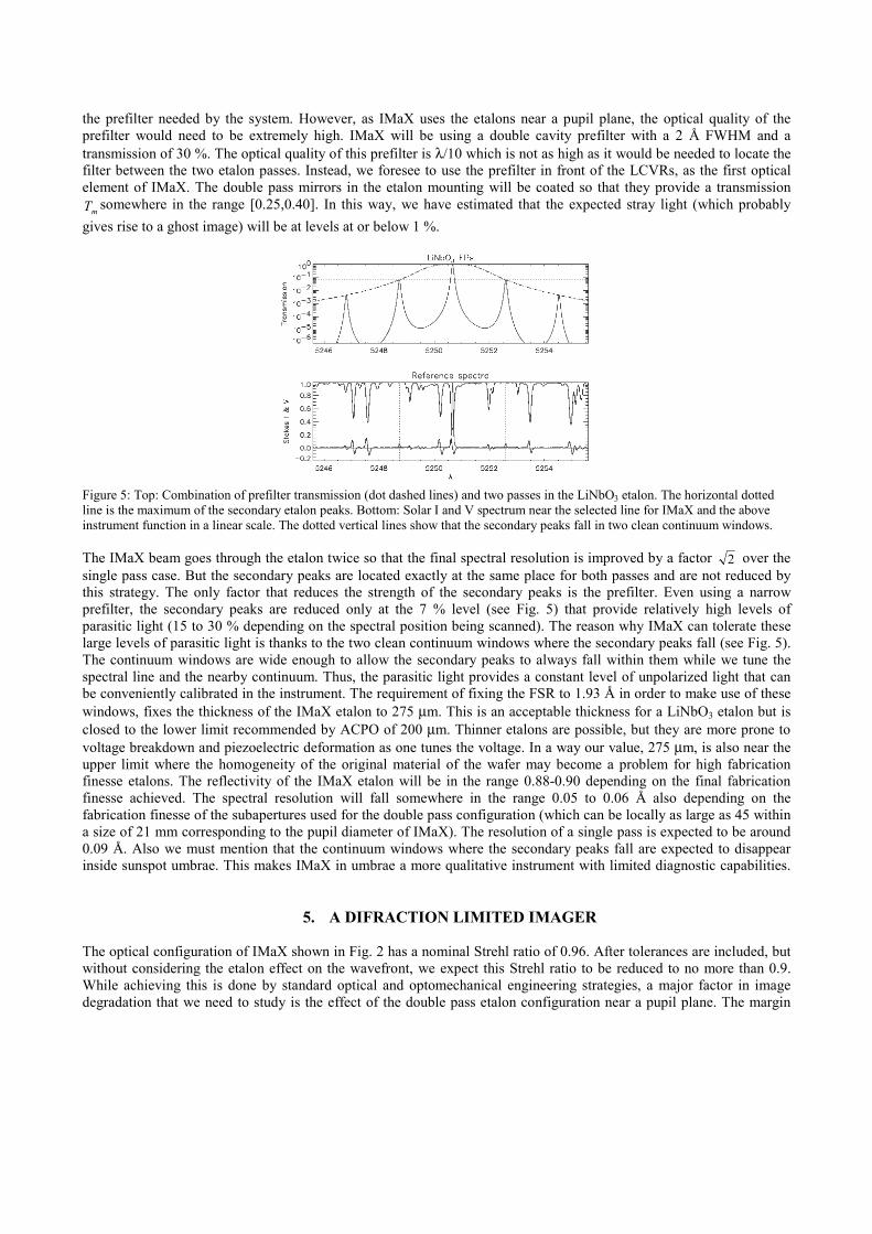
Figure 5: Top: Combination of prefilter transmission (dot dashed lines) and two passes in the LiNbO3 etalon. The horizontal dotted line is the maximum of the secondary etalon peaks. Bottom: Solar I and V spectrum near the selected line for IMaX and the above instrument function in a linear scale. The dotted vertical lines show that the secondary peaks fall in two clean continuum windows. The IMaX beam goes through the etalon twice so that the final spectral resolution is improved by a factor 2 over the single pass case. But the secondary peaks are located exactly at the same place for both passes and are not reduced by this strategy. The only factor that reduces the strength of the secondary peaks is the prefilter. Even using a narrow prefilter, the secondary peaks are reduced only at the 7 % level (see Fig. 5) that provide relatively high levels of parasitic light (15 to 30 % depending on the spectral position being scanned). The reason why IMaX can tolerate these large levels of parasitic light is thanks to the two clean continuum windows where the secondary peaks fall (see Fig. 5). The continuum windows are wide enough to allow the secondary peaks to always fall within them while we tune the spectral line and the nearby continuum. Thus, the parasitic light provides a constant level of unpolarized light that can be conveniently calibrated in the instrument. The requirement of fixing the FSR to 1.93 Å in order to make use of these windows, fixes the thickness of the IMaX etalon to 275 µm. This is an acceptable thickness for a LiNbO3 etalon but is closed to the lower limit recommended by ACPO of 200 µm. Thinner etalons are possible, but they are more prone to voltage breakdown and piezoelectric deformation as one tunes the voltage. In a way our value, 275 µm, is also near the upper limit where the homogeneity of the original material of the wafer may become a problem for high fabrication finesse etalons. The reflectivity of the IMaX etalon will be in the range 0.88-0.90 depending on the final fabrication finesse achieved. The spectral resolution will fall somewhere in the range 0.05 to 0.06 Å also depending on the fabrication finesse of the subapertures used for the double pass configuration (which can be locally as large as 45 within a size of 21 mm corresponding to the pupil diameter of IMaX). The resolution of a single pass is expected to be around 0.09 Å. Also we must mention that the continuum windows where the secondary peaks fall are expected to disappear inside sunspot umbrae. This makes IMaX in umbrae a more qualitative instrument with limited diagnostic capabilities.
5. A DIFRACTION LIMITED IMAGER The optical configuration of IMaX shown in Fig. 2 has a nominal Strehl ratio of 0.96. After tolerances are included, but without considering the etalon effect on the wavefront, we expect this Strehl ratio to be reduced to no more than 0.9. While achieving this is done by standard optical and optomechanical engineering strategies, a major factor in image degradation that we need to study is the effect of the double pass etalon configuration near a pupil plane. The margin
left to achieve an overall IMaX Strehl ratio larger than 0.8 is not very large. In this section we show how the current estimates that we have are capable of guaranteeing such a performance. The absolute phase of the wavefront after passing through an etalon filter, φ , is given by13-14:
hn´2)cos1(
sinarctanλπ
δδφ +
ℜ−ℜ=
where all the factors have been introduced already. For a perfect etalon ohh = and at the reference wavelength oλ one
has that πλπδδ mhn oo
o 2´4 === providing a null contribution to the phase from the first term of the right hand side of
equation (8). The output wavefront has then a uniform value equal to o
oo hn´2
λπφ = . This last term in equation (8) is the
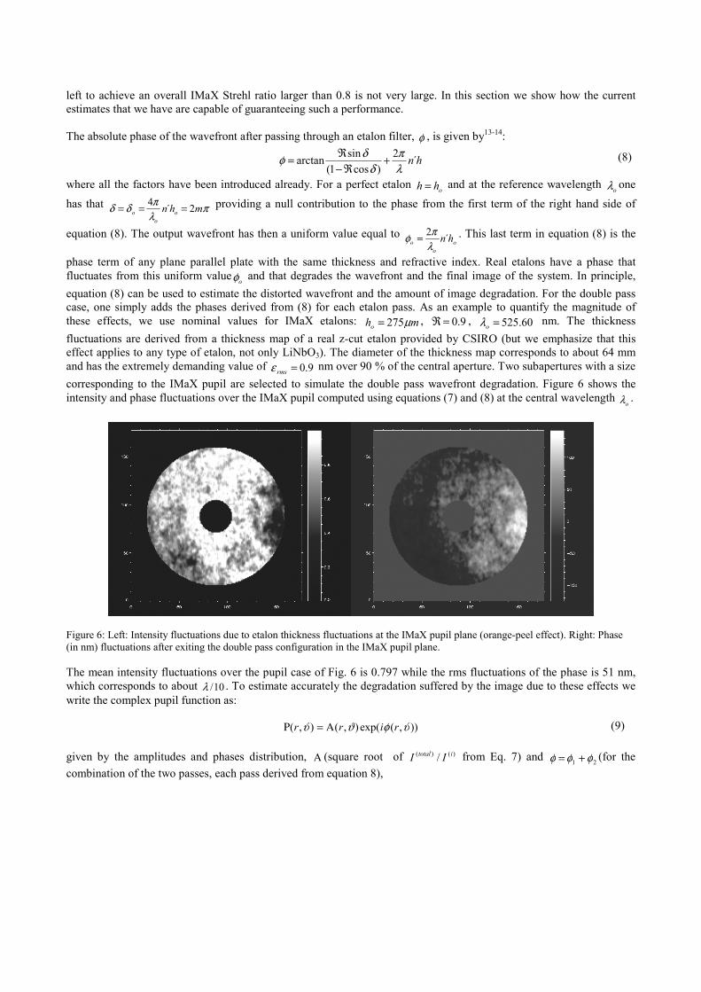
phase term of any plane parallel plate with the same thickness and refractive index. Real etalons have a phase that fluctuates from this uniform value oφ and that degrades the wavefront and the final image of the system. In principle, equation (8) can be used to estimate the distorted wavefront and the amount of image degradation. For the double pass case, one simply adds the phases derived from (8) for each etalon pass. As an example to quantify the magnitude of these effects, we use nominal values for IMaX etalons: mho µ275= , 9.0=ℜ , 60.525=oλ nm. The thickness fluctuations are derived from a thickness map of a real z-cut etalon provided by CSIRO (but we emphasize that this effect applies to any type of etalon, not only LiNbO3). The diameter of the thickness map corresponds to about 64 mm and has the extremely demanding value of 9.0=rmsε nm over 90 % of the central aperture. Two subapertures with a size corresponding to the IMaX pupil are selected to simulate the double pass wavefront degradation. Figure 6 shows the intensity and phase fluctuations over the IMaX pupil computed using equations (7) and (8) at the central wavelength
oλ .
Figure 6: Left: Intensity fluctuations due to etalon thickness fluctuations at the IMaX pupil plane (orange-peel effect). Right: Phase (in nm) fluctuations after exiting the double pass configuration in the IMaX pupil plane. The mean intensity fluctuations over the pupil case of Fig. 6 is 0.797 while the rms fluctuations of the phase is 51 nm, which corresponds to about 10/λ . To estimate accurately the degradation suffered by the image due to these effects we write the complex pupil function as:
)),(exp(),(),( ϑφϑϑ rirr Α=Ρ
given by the amplitudes and phases distribution, Α (square root of )()( / itotal II from Eq. 7) and 21 φφφ += (for the combination of the two passes, each pass derived from equation 8),
(8)
(9)
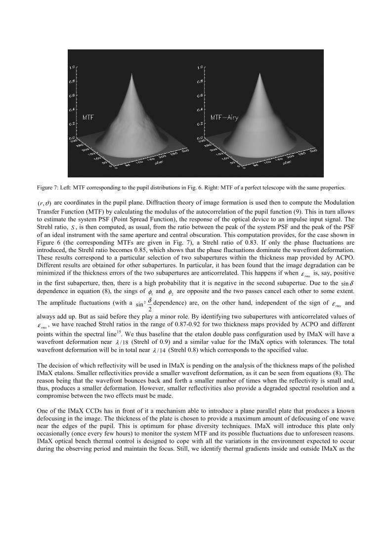
Figure 7: Left: MTF corresponding to the pupil distributions in Fig. 6. Right: MTF of a perfect telescope with the same properties.
),( ϑr are coordinates in the pupil plane. Diffraction theory of image formation is used then to compute the Modulation Transfer Function (MTF) by calculating the modulus of the autocorrelation of the pupil function (9). This in turn allows to estimate the system PSF (Point Spread Function), the response of the optical device to an impulse input signal. The Strehl ratio, S , is then computed, as usual, from the ratio between the peak of the system PSF and the peak of the PSF of an ideal instrument with the same aperture and central obscuration. This computation provides, for the case shown in Figure 6 (the corresponding MTFs are given in Fig. 7), a Strehl ratio of 0.83. If only the phase fluctuations are introduced, the Strehl ratio becomes 0.85, which shows that the phase fluctuations dominate the wavefront deformation. These results correspond to a particular selection of two subapertures within the thickness map provided by ACPO. Different results are obtained for other subapertures. In particular, it has been found that the image degradation can be minimized if the thickness errors of the two subapertures are anticorrelated. This happens if when rmsε is, say, positive in the first subaperture, then, there is a high probability that it is negative in the second subapertue. Due to the δsin dependence in equation (8), the sings of 1φ and 2φ are opposite and the two passes cancel each other to some extent.
The amplitude fluctuations (with a 2
sin 2 δ dependence) are, on the other hand, independent of the sign of rmsε and
always add up. But as said before they play a minor role. By identifying two subapertures with anticorrelated values of rmsε , we have reached Strehl ratios in the range of 0.87-0.92 for two thickness maps provided by ACPO and different
points within the spectral line15. We thus baseline that the etalon double pass configuration used by IMaX will have a wavefront deformation near 18/λ (Strehl of 0.9) and a similar value for the IMaX optics with tolerances. The total wavefront deformation will be in total near 14/λ (Strehl 0.8) which corresponds to the specified value. The decision of which reflectivity will be used in IMaX is pending on the analysis of the thickness maps of the polished IMaX etalons. Smaller reflectivities provide a smaller wavefront deformation, as it can be seen from equations (8). The reason being that the wavefront bounces back and forth a smaller number of times when the reflectivity is small and, thus, produces a smaller deformation. However, smaller reflectivities also provide a degraded spectral resolution and a compromise between the two effects must be made. One of the IMaX CCDs has in front of it a mechanism able to introduce a plane parallel plate that produces a known defocusing in the image. The thickness of the plate is chosen to provide a maximum amount of defocusing of one wave near the edges of the pupil. This is optimum for phase diversity techniques. IMaX will introduce this plate only occasionally (once every few hours) to monitor the system MTF and its possible fluctuations due to unforeseen reasons. IMaX optical bench thermal control is designed to cope with all the variations in the environment expected to occur during the observing period and maintain the focus. Still, we identify thermal gradients inside and outside IMaX as the
most likely source of MTF degradation that recommends the use of phase diversity monitoring. The phase diversity correction will be applied during the data analysis.
6. DATA ACQUISITION AND HANDLING IMaX uses two custom-made CCD detectors by Photonics Science Limited (UK). The CCDs are based on the E2V 47-20 AIMO scientific (grade 1) quality sensor, back illuminated chip. The active area has 1024 x 1024 pixels 13 µm square, run in special low noise AIMO operation with image section clocks adjusted to give extended well depth of 120,000 e-. The storage area comprises1024 x 1033 similar pixels run as NIMO allowing faster transfer from store. Storage area is dithered to stop build up of dark current. The quantum efficiency of the detector is expected to be larger than 90 % for the IMaX wavelengths. They provide 14 bit resolution and allow for operation based on external triggering adequate for synchronization with the LCVRs and the etalons. The cameras are expected to run at 5 frames per second with a transfer time to the storage area of 10.48 ms. A maximum speed of 7 frames per second can be achieved. The cameras run at 0 oC with a readout noise of 45 e- and a dark current level of 21 e-/px/s. The cameras are expected to consume less than 30 W and weight about 2.5 kg. This weight estimate includes the housing that acts as a pressurized vessel. The cameras have a window made of fused silica with 4 mm thickness that allows the light to reach the detector and keep the pressure at 1 atmosphere inside. The cameras thermal control is made by a thermal connection between sensor and heat pipe interface using aluminum conductor. The heat pipe is connected to a radiator on top of the IMaX optical bench cover used for thermal control of all dissipating components. We estimate that a total of 105,000 photons will be available at a rate of 5 frames per second, producing 94,000 e-. This represents almost 80 % of the detector’s well depth. For the expected polarization modulation efficiencies we need to accumulate 5 frames to reach the desired S/N in vectorial mode and 3 in longitudinal mode. The final numbers will depend on the speed of on-board data processing including compression of images. The most demanding observing mode (vectorial with 5 wavelength positions) is expected to take less than 30 seconds.
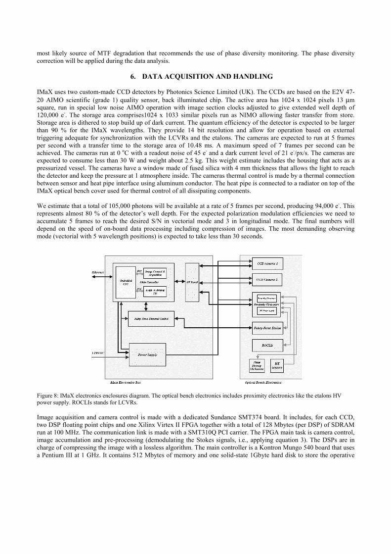
Figure 8: IMaX electronics enclosures diagram. The optical bench electronics includes proximity electronics like the etalons HV power supply. ROCLIs stands for LCVRs. Image acquisition and camera control is made with a dedicated Sundance SMT374 board. It includes, for each CCD, two DSP floating point chips and one Xilinx Virtex II FPGA together with a total of 128 Mbytes (per DSP) of SDRAM run at 100 MHz. The communication link is made with a SMT310Q PCI carrier. The FPGA main task is camera control, image accumulation and pre-processing (demodulating the Stokes signals, i.e., applying equation 3). The DSPs are in charge of compressing the image with a lossless algorithm. The main controller is a Kontron Mungo 540 board that uses a Pentium III at 1 GHz. It contains 512 Mbytes of memory and one solid-state 1Gbyte hard disk to store the operative
system (Windows NT). The main task of this main controller is to establish the synchronism of all subsystems during image acquisition, communication with the Instrument Control Unit (ICU) of the SUNRISE experiment including all housekeeping and image processed data, the control of secondary power supplies and the booting of subsystems. The main controller sends to the ICU all processed data for saving in the mass storage system. The average communication bandwidth is 660 Kbytes/s that is expected to provide for the total duration of the flight 800 Gbytes of data. If IMaX were to observe continuously during the whole flight, these bandwidths are around half the data rates needed. The main controller, the image acquisition board, power supplies and interface boards are part of the pressurized main electronic enclosure located on the side of the SUNRISE gondola. IMaX uses a smaller pressurised enclosure in the optical bench containing proximity electronics that should not be accommodated in the main enclosure. This proximity electronics includes the HV etalon power supply (hence avoiding long distance HV lines in a near vacuum environment) that must be able to supply the voltages needed for the etalon tuning (typically ± 3500 V). The bipolar power supply HP3RZ from Applied Kilovolts has been selected for this task. In the same enclosure and with an electromagnetic shield to avoid noise from the HV power supply, an FPGA is included along with a number of electronic components. Among these, we include the phase diversity actuator, LCVR controllers, housekeeping sensors, A/D and D/A converters and thermal actuators. A non-operative thermostat line (directly provided by SUNRISE) useful during the ascent of the balloon is also included in this enclosure.
7. CONCLUSIONS We have described, at a conceptual level, the current definition of the magnetograph that will fly in SUNRISE. An autonomous operation magnetograph has never been constructed in Europe to our knowledge. We propose here the use of solutions that need of a minimal number of mechanisms like the use of electro-optical devices like LCVRs and LiNbO3 etalons. This combination is actually not new, as it was adopted (in a slightly different way) by the Antarctica experiment Flare Genesis16 magnetograph developed by APL. Although the IMaX concept presented here is very detailed in terms of optical, optomechanical and electronic definition, other aspects are still being developed. Flare Genesis experience clearly recommended a thorough thermal analysis (including using free expansion materials) at instrument and system levels and a careful optical alignment with clear cleanliness requirements and shipment policy. IMaX thermal control and AIV phases are currently undergoing preliminary definition. The software and ground support equipment policy are also starting their definition phases. Our current IMaX concept fulfils the stringent requirements in terms of polarimetric accuracy, spectral resolution and image quality and will allow starting its construction phase for final procurement to the SUNRISE PI institution at the end of 2005. The instrument is being entirely developed and funded by a consortium of four astronomy and space institutions in Spain. It represents an important step in the involvement of our consortium in the development of a similar instrument for the ESA Solar Orbiter mission.
ACKNOWLEDGEMENTS This project is funded by the Spanish Programa Nacional del Espacio under project ESP2003-07735.
REFERENCES 1. Scharmer, G.B., Gudiksen, B., Kiselman, D., Löfdahl, M.G., and Rouppe van der Voort, L.H.M., ``Dark cores in
Sunspot penumbral filaments’’, Nature, 420, pp. 151-153, 2002 2. Gandorfer, A.M., Solanki, S.K., Schüssler, M., Curdt, W., Martínez Pillet, V., Schmidt, W., and Lites, B.W., Title,
A.M., ``SUNRISE: high resolution UV/Vis observations of the Sun from the stratosphere´´, SPIE 5489-57, in press 3. Bittner, H., Erdmann, M., Haberler, P., Härtel, K., Curdt, W., and Barthol, P., ``Baseline design of the SUNRISE
telescope´´, SPIE 5489-126, in press 4. Schmidt, W., Berkefeld, T., Friedlein, R., Heidecke, F., Kentischer, T., Sigwarth, M., and Soltau, D., ``High-
precision wavefront sensor for the SUNRISE telescope´´, SPIE 5489-140, in press

5. Jochum, L., Collados, M., Martínez Pillet, V., Bonet, J. A., del Toro Iniesta, J. C., Lopez, A., Alvarez-Herrero, A., Reina, M., Fabregat, J., and Domingo, V.,`` IMaX: a visible magnetograph for SUNRISE´´, SPIE 4843, pp. 20-29, 2003
6. Jochum, L., Herrero, P., Collados, M., Martínez Pillet, V., Rodríguez, J., and López, M.,``Liquid crystal optical retarders for IMaX to fly with SUNRISE´´, SPIE 4843, pp. 30-38, 2003
7. Sánchez Almeida, J., Collados, M., and Martínez Pillet, V., ``Modulation Schemes for the polarimeter of the SVST´´, IAC internal report, 1994
8. del Toro Iniesta, J.C., and Collados, M., ``Optimum modulation and demodulation matrices for solar polarimetry´´, Appl. Optics, 39, pp 1637-1642, 2000
9. Heredero, R.L., Martínez Pillet, V., López Jiménez, A., Alvarez Herrero, A., ``Gamma Radiation effects on the optical properties of Liquid Cristal Variable Retarders´´, RADEC 2004, submitted
10. Born, M., and Wolf, E., ``Principles of Optics´´, Pergamon Press, 1989 11. Atherton, P.D., Reay, N.K., Ring, J., and Hicks, T.R., Tunable Fabry-Perot filters, Optical Engineering, 20, No 6,
pp. 806-814, 1982 12. Skinner, W.R., Hays, P.B., and Abreu, V.J., Optimisation of a triple etalon interferometer, Appl. Optics, 26, No. 14,
2817-2827, 1987 13. von der Lühe, O., and Kentischer, T., ``High spatial resolution performance of a triple Fabry-Perot filtergraph´´,
Astron. Astrophys. Suppl. Ser., 146, 499-506, 2000 14. Martínez Pillet, V., IMaX Technical Note, ``Rationale for a low reflective finesse for the LiNbO3 etalons for
IMaX´´, SUN-IMaX-TN-IX200-009, 2003 15. Martínez Pillet, V., and Bonet, J.A., IMaX Technical Note, ``Amplitude and phase variations in double pass
LiNbO3 etalons: Simulations from thickness maps´´, SUN-IMaX-TN-IX200-015, 2004 16. Bernasconi, P., Rust, D., Eaton, H., and Murphy, G., ``A balloon-borne telescope for high resolution solar imaging
and polarimetry´´, SPIE, 4014, pp. 214-225, 2000