Embed Size (px)
Citation preview
2
The Internal Flow Investigation of a Centrifugal Pump
by
A. Akhras, M. El Hajem, R. Morel, J.Y. Champagne
Laboratoire de Mécanique des Fluides
Bât 302, 20 av. A. Einstein, 69621 Villeurbanne; France
ABSTRACT
This paper provides the results of a detailed flow investigation within a centrifugal pump equipped with a vaneddiffuser. The measurements made with a laser-Doppler velocimeter were carried out at the impeller design point. In aprevious paper concerning the same machine, El Hajem (1998) found a jet-wake structure developing at the impellerexit. During the actual study, measurements were obtained in the impeller and the diffuser at different measuring planesrelative to the diffuser vanes. Results are presented as animations reconstituting a temporal evolution of the flow at thediffuser inlet.
Unsteady velocity measurements obtained in phase with the impeller angular position gave access to the flow inside theimpeller channels where three sections were explored. For each section, results were obtained as a function of theposition of impeller blades relative to the diffuser vanes. Thus time resolved details of the flow could be examined for abetter understanding of the complex unsteady flow existing between the two interacting blade rows.
The analysis of the impeller flow field indicates the presence of a complex, unsteady and periodic flow. It is organisedin a jet-wake structure. The wake is characterised by low relative velocities and is localised in the suction side/shroudcorner. At this flow rate, it seems that presence of the vanes has only a limited effect on the impeller flow structure,except when the blades suction side are facing the diffuser vanes.
At the impeller discharge, the time-resolved sequences show that the mixing process of the unsteady and periodic flowleaving the impeller is affected by the presence of the diffuser. At the leading edge, at the suction side of diffuser vanes,the flow is rapidly mixed. Whereas, when approaching the diffuser throat, the flow still shows its periodic characterobserved at the impeller outlet. This indicates that the diffuser is subject to unsteady inlet conditions that can alter itsperformances.
3
I INTRODUCTION
During the design of a turbomachine, the flow is considered steady and uniform at the entry of each element. For acentrifugal pump with a vaned diffuser, satisfying this assumption requires a large interface between the rotor and thestator so that the mixing process of the flow leaving the impeller can take place. Otherwise, the unsteady flow thatenters the diffuser represents a source of low efficiency. Furthermore, the internal flow of the impeller can be affectedby asymmetric downstream conditions, which results in extra flow unsteadiness and instabilities. A number of authorshave treated the problem of the interaction of the impeller and its surrounding. Miner [1] used a laser velocimeter tomeasure velocities within the impeller and the volute of a centrifugal pump and found that the relative velocitycomponents distribution varies with the circumferential angle relative to the volute cutwater. Liu (1994) has also usedLDA for the internal flow investigation and found that the asymmetric volute alters the relative flow, the flow rate fromeach impeller passage varied with the volute circumferential position by up to 25 percent at an off-design flow rate.Inoue (1984), Sideris (1987) and Arndt (1989, 1990) have been concerned with the action of the diffuser. For internalflow studies, a large number of the experimental investigations that revealed the presence of a jet-wake structure at thedischarge of centrifugal rotors was concerned with compressors as done by Eckardt (1975, 1976), Johnston (1976),Johnson (1978), and more recently Rohne (1991) and Ubaldi (1993). However, Krain (1988) found a velocity profilethat differed widely from the jet-wake type flow. In a previous study, the authors (El Hajem et al., 1998) found a jet-wake structure developing at the impeller exit During this study, LDA measurements, revealed the presence of a jet-wake flow structure. The location and the extension of the wake seem to be affected by the proximity of the diffuservanes.
II EXPERIMENTAL SETUP
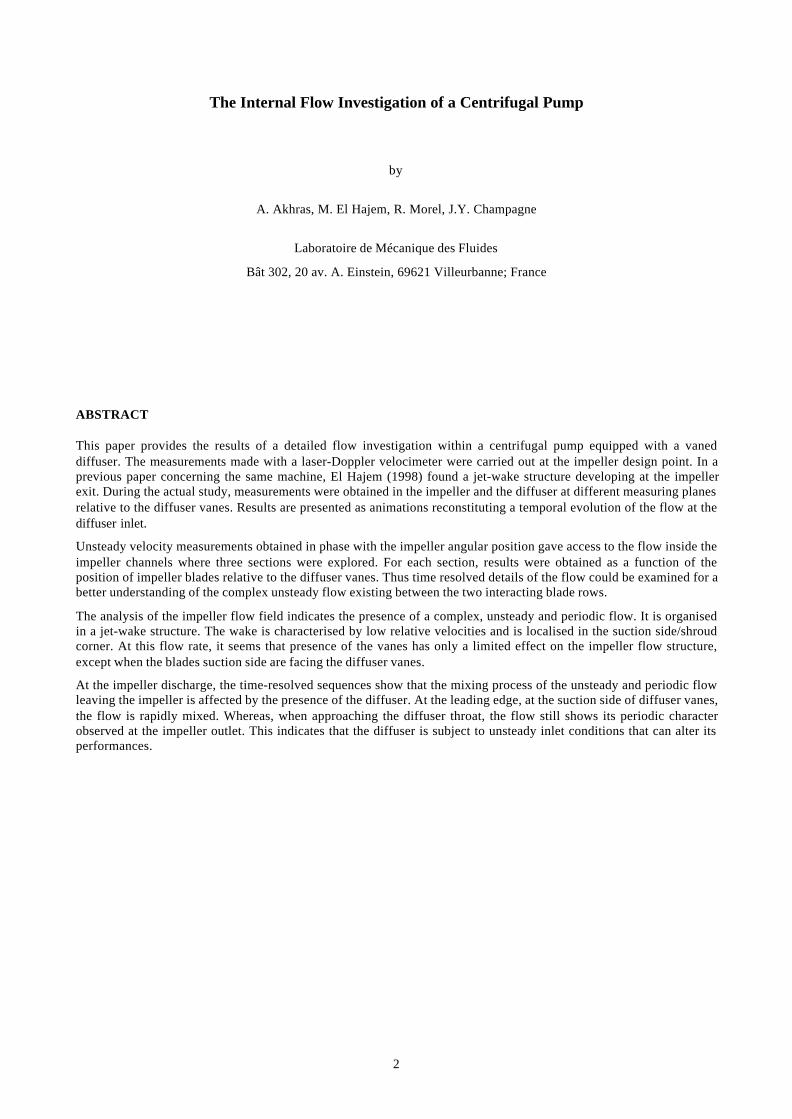
II.1 THE SHF IMPELLERThe test impeller, shown in Figure 1, is a low specific speed (ωs=0.577) shrouded impeller. It has seven backsweptblades with an exit angle of 22.5 degrees relative to the tangential direction. The main geometric data of the impellerand its operating conditions are resumed in table 1. For optic access, the shroud was made out of clear Plexiglas and aclear window was realized on the casing. The impeller was run with a vaned diffuser and a spiral casing of industrialtype. The diffuser is a straight wall constant width with six vanes (Figure 1). The main dimensions of the diffuser arelisted in table 2.
II.2 TEST RIGExperiments were performed on a centrifugal pump test facility (1, figure 2) consisting of a closed rig equipped for theoverall performance characterization of the machine. Water enters the impeller through a straight suction pipe of 1.4 min length. The net flow rate traversing the pump is measured by an electromagnetic flow meter (11, figure 2) with aprecision of 0.2 percent at the actual experimental conditions. The impeller is driven by a variable speed DC motor of45 kW power at 1500 rpm mounted in balance mode for torque measurement (10, figure 2).
Figure 1 : Test impeller and vaned diffuser Figure 2 : Test rig Measuring equipment
4
Table 1 Impeller characteristics
impeller parameter descriptionR1 = 98.25 mm inlet blade radius at the shroudR2 = 177.25 mm impeller exit radiusb = 26.7 mm blade heightZ = 7 blade numberβ2 = 22.5 deg. blade angleQn = 0.0774 m3/s design flow rateN = 1188 Rpm rotational speedφ = 0.118 Design flow coefficientψ = 0.481 Design head coefficientω = 0.577 specific speed
Table 2 Diffuser characteristics
diffuser parameter descriptionR3 = 182 mm diffuser inlet radiusR4 = 199.3 mm Leading edge radiusR5 = 258 mm diffuser exit radiusb3 = 28.1 mm Diffuser widthZ = 6 Vane numberα3 = 12 deg. Vane angle
Table 3 Measuring Sections
Angular positionin the diffuser
pitchα (deg)
r* = r/R2
0.81820.9092In the impeller0.97841.01791.04511.08461.1298
IIIIIIIVVVIVII
0 (or 60)101730435057
In the Diffuser
1.198
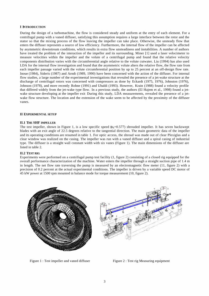
Figure 3 : Research centrifugal pump with LDA optics
Figure 4 : Optic access to the measuring vane
II.3 MEASURING EQUIPMENTMeasurements of velocity distribution at the impeller discharge and in the diffuser were obtained by using an LDAsystem. The light source is a 5 W argon ion laser operating in multiline mode in order to operate with the blue (488 nm)and green (514.5 nm) wavelengths. Modular optics with a 310 mm focusing lens are used to derive a three beamconfiguration. The LDA system was used in a back-scatter mode. The optical components, including the laser and thephotomultipliers, were mounted on a three axis traversing system to place the probe volume at the location of interest(figures 3, 4).To relate the velocity measurement to the angular position of the impeller, an optical encoder is used to synchronizemeasurement with machinery. The encoder fixed on the pump shaft gives the position of the measuring point in theblade-to-blade plane with a resolution of 3600 angular readings for one shaft revolution.For each test point M in the axial direction, an average of 10 000 data points were taken. The sampling rate wasarbitrary and depended on the nature of the LDA signals. The data processing system, consisting of two burst signalanalyzers with built-in synchronization inputs for cyclic phenomena, is connected to a PC. A software uses encoderpulses to phase-sort the velocity samples versus the phase angle. The Data is also phase-averaged to compute the meanvelocity and the turbulence intensity.In order to study the interaction of the impeller and the diffuser, the flow was investigated at 7 radial planes located atdifferent angular positions in the diffuser as given on table 3 and shown on figure 5. For each plane, the flow wasinvestigated at eight radial sections in the impeller and the diffuser (table 3), for each radii, sixteen points wereexplored.
5
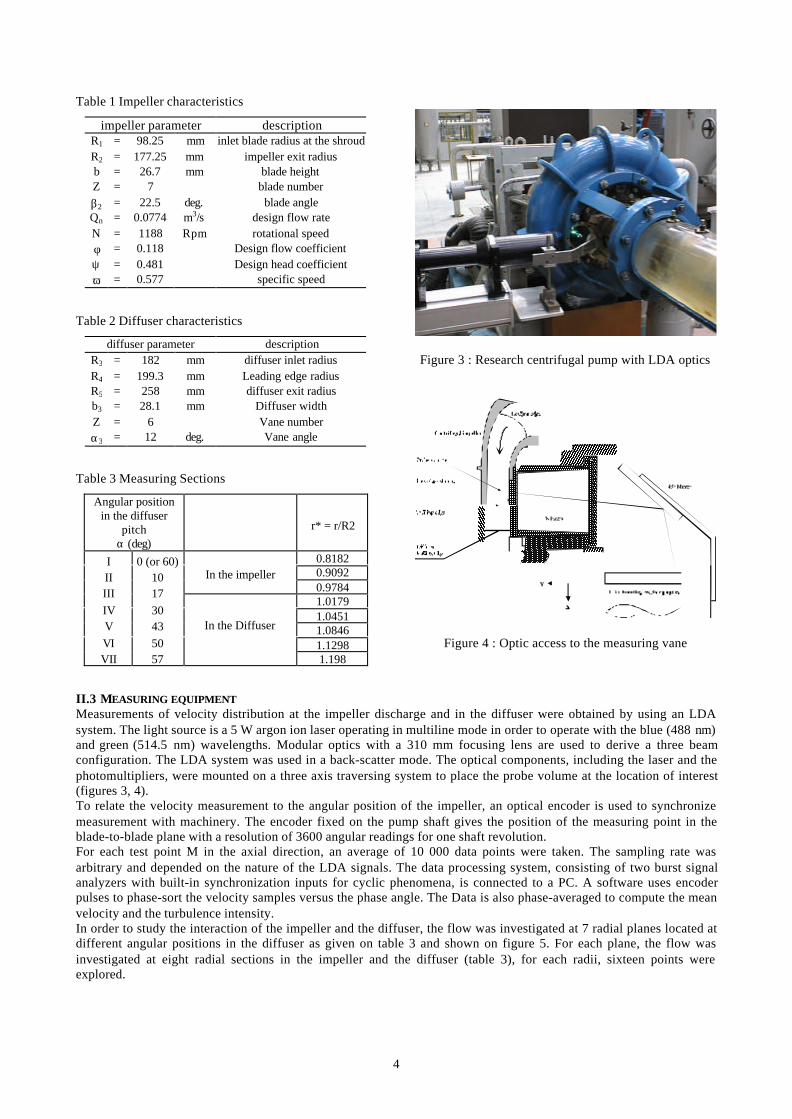
Figure 5 : Locations of the measurement planes within the impeller and the diffuser
0 90 180 270 360Angular position (deg)
0
5
10
15
20
Cr,
Cu
(m/s
)
CrCur/R2 = 0.818
z/b = 0.5
0 90 180 270 360Angular position (deg)
0
5
10
15
20
Cr,
Cu
(m/s
)
CrCur/R2 = 0.909
z/b = 0.5
0 90 180 270 360Angular position (deg)
0
5
10
15
20
Cr,
Cu
(m/s
)
CrCur/R2 = 0.978
z/b = 0.5
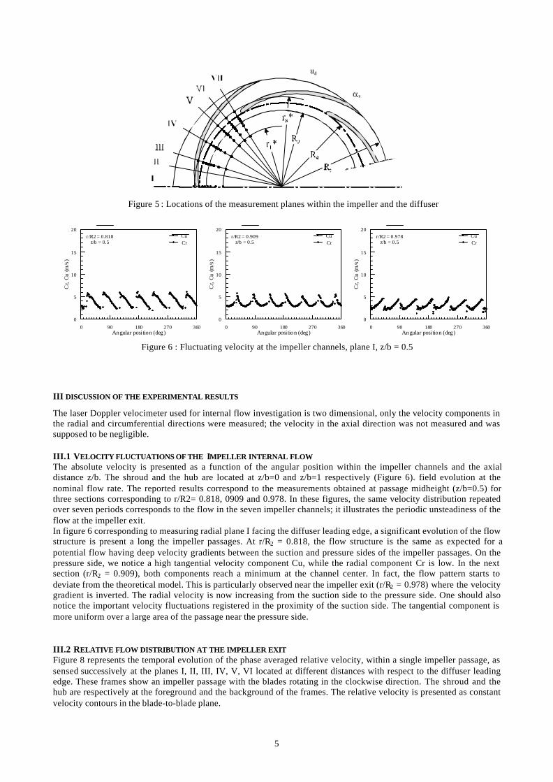
Figure 6 : Fluctuating velocity at the impeller channels, plane I, z/b = 0.5
III DISCUSSION OF THE EXPERIMENTAL RESULTS
The laser Doppler velocimeter used for internal flow investigation is two dimensional, only the velocity components inthe radial and circumferential directions were measured; the velocity in the axial direction was not measured and wassupposed to be negligible.
III.1 VELOCITY FLUCTUATIONS OF THE IMPELLER INTERNAL FLOWThe absolute velocity is presented as a function of the angular position within the impeller channels and the axialdistance z/b. The shroud and the hub are located at z/b=0 and z/b=1 respectively (Figure 6). field evolution at thenominal flow rate. The reported results correspond to the measurements obtained at passage midheight (z/b=0.5) forthree sections corresponding to r/R2= 0.818, 0909 and 0.978. In these figures, the same velocity distribution repeatedover seven periods corresponds to the flow in the seven impeller channels; it illustrates the periodic unsteadiness of theflow at the impeller exit.In figure 6 corresponding to measuring radial plane I facing the diffuser leading edge, a significant evolution of the flowstructure is present a long the impeller passages. At r/R2 = 0.818, the flow structure is the same as expected for apotential flow having deep velocity gradients between the suction and pressure sides of the impeller passages. On thepressure side, we notice a high tangential velocity component Cu, while the radial component Cr is low. In the nextsection (r/R2 = 0.909), both components reach a minimum at the channel center. In fact, the flow pattern starts todeviate from the theoretical model. This is particularly observed near the impeller exit (r/R2 = 0.978) where the velocitygradient is inverted. The radial velocity is now increasing from the suction side to the pressure side. One should alsonotice the important velocity fluctuations registered in the proximity of the suction side. The tangential component ismore uniform over a large area of the passage near the pressure side.
III.2 RELATIVE FLOW DISTRIBUTION AT THE IMPELLER EXITFigure 8 represents the temporal evolution of the phase averaged relative velocity, within a single impeller passage, assensed successively at the planes I, II, III, IV, V, VI located at different distances with respect to the diffuser leadingedge. These frames show an impeller passage with the blades rotating in the clockwise direction. The shroud and thehub are respectively at the foreground and the background of the frames. The relative velocity is presented as constantvelocity contours in the blade-to-blade plane.
6
W (m /s)20
17
13
10
7
3
0
Plane I
W (m /s)20
17
13
10
7
3
0
Plane II
W (m /s)20
17
13
10
7
3
0
Plane IIIW (m /s)
20
17
13
10
7
3
0
Plane IV
W (m /s)20
17
13
10
7
3
0
Plane V
W (m /s)20
17
13
10
7
3
0
Plane VI
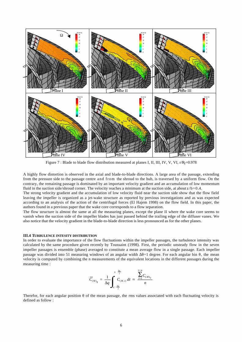
Figure 7 : Blade to blade flow distribution measured at planes I, II, III, IV, V, VI, r/R2=0.978
A highly flow distortion is observed in the axial and blade-to-blade directions. A large area of the passage, extendingfrom the pressure side to the passage centre and f rom the shroud to the hub, is traversed by a uniform flow. On thecontrary, the remaining passage is dominated by an important velocity gradient and an accumulation of low momentumfluid in the suction side/shroud corner. The velocity reaches a minimum at the suction side, at about z/b=0.4.The strong velocity gradient and the accumulation of low velocity fluid near the suction side show that the flow fieldleaving the impeller is organized as a jet-wake structure as reported by previous investigations and as was expectedaccording to an analysis of the action of the centrifugal forces (El Hajem 1998) on the flow field. In this paper, theauthors found in a previous paper that the wake core corresponds to a flow separation.The flow structure is almost the same at all the measuring planes, except the plane II where the wake core seems tovanish when the suction side of the impeller blades has just passed behind the trailing edge of the diffuser vanes. Wealso notice that the velocity gradient in the blade-to-blade direction is less pronounced as for the other planes.
III.4 TURBULENCE INTESITY DISTRIBUTIONIn order to evaluate the importance of the flow fluctuations within the impeller passages, the turbulence intensity wascalculated by the same procedure given recently by Toussaint (1998). First, the periodic unsteady flow in the sevenimpeller passages is ensemble (phase) averaged to constitute a mean average flow in a single passage. Each impellerpassage was divided into 51 measuring windows of an angular width ∆θ=1 degree. For each angular bin θ, the meanvelocity is computed by combining the n measurements of the equivalent locations in the different passages during themeasuring time :
n
CdtCC
M
tMM
ni
i θ
θθ
θθ
θθ
)(
),()(1
2
2
1
=
=Σ
∫∆+
∆−
≈∆
=
Therefor, for each angular position θ of the mean passage, the rms values associated with each fluctuating velocity isdefined as follow :
Ω
7
0 10 20 30 40 50Angular position (deg)
0
20
40
60
80
100T
u (%
)
Tu (Cr)Tu (Cu)
r/R2 = 0.978z/ b = 0.17Plane I
0 10 20 30 40 50Angular position (deg)
0
20
40
60
80
100
Tu
(%)
Tu (Cr)Tu (Cu)
r/R2 = 0.978z/ b = 0.5Plane I
0 10 20 30 40 50Angular position (deg)
0
20
40
60
80
100
Tu
(%)
Tu (Cr)Tu (Cu)
r/R2 = 0.978z/b = 0.85P lane I
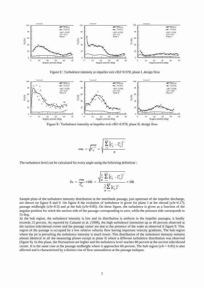
Figure 8 : Turbulence intensity at impeller exit r/R2=0.978, plane I, design flow
0 10 20 30 40 50Angular position (deg)
0
20
40
60
80
100
Tu
(%)
Tu (Cr)Tu (Cu)
r/R2 = 0.978z/ b = 0.17Plane II
0 10 20 30 40 50Angular position (deg)
0
20
40
60
80
100
Tu
(%)
Tu (Cr)Tu (Cu)
r/R2 = 0.978z/ b = 0.5Plane II
0 10 20 30 40 50Angular position (deg)
0
20
40
60
80
100
Tu
(%)
Tu (Cr)Tu (Cu)
r/R2 = 0.978z/ b = 0.85Plane II
Figure 9 : Turbulence intensity at impeller exit r/R2=0.978, plane II, design flow
[ ]n
CCCrms
ni
i
2
12'θθ
θ
−==
=
=Σ
The turbulence level can be calculated for every angle using the following definition :
[ ]
[ ]100
1
1
1002
2
1
1 ×−
=×==
=
=
=
Σ
Σ
θ
θθ
θ Cn
CCn
Crms
Tuni
i
ni
i
Sample plots of the turbulence intensity distribution in the interblade passage, just upstream of the impeller discharge,are shown on figure 8 and 9. On figure 8 the evolution of turbulence is given for plane I at the shroud (z/b=0.17),passage midheight (z/b=0.5) and at the hub (z/b=0.85). On these figure, the turbulence is given as a function of theangular position for witch the suction side of the passage corresponding to zero, while the pressure side corresponds to51 deg.At the hub region, the turbulence intensity is low and its distribution is uniform in the impeller passages, it hardlyexceeds 15 percent. As reported by Cattanei et al. (1998), the high turbulence intensities up to 40 percent observed atthe suction side/shroud corner and the passage center are due to the presence of the wake as observed if figure 9. Thisregion of the passage is occupied by a low relative velocity flow having important velocity gradients. The hub regionwhere the jet is prevailing the turbulence intensity is much lower. This distribution of the turbulence intensity remainsalmost identical in all the measuring planes except at plane II where a different turbulence distribution was observed(figure 9). In this plane, the fluctuations are higher and the turbulence level reaches 80 percent at the suction side/shroudcorner. It is the same case at the passage midheight where it approaches 60 percent. The hub region (z/b = 0.85) is alsoaffected and is characterized by a distinct rise of flow unsteadiness at the passage midspan.
8
C
17.836715.510212.40829.306126.979594.653062.326530
T 1
R 1
R 2
S 2
S 1
I
I II II
IV
V
VI
VII
C
17.836715.510212.40829.306126.979594.653062.326530
T 11
R 1
R 2
S 2
S 1
I
I II II
IV
V
VI
VII
C
17.836715.510212.40829.306126.979594.653062.326530
T 31
R 1
R 2
S 2
S 1
I
I II II
IV
V
VI
VII
C
17.836715.510212.40829.306126.979594.653062.326530
T 41
R 1
R 2
S 2
S 1
I
I II II
IV
V
VI
VII
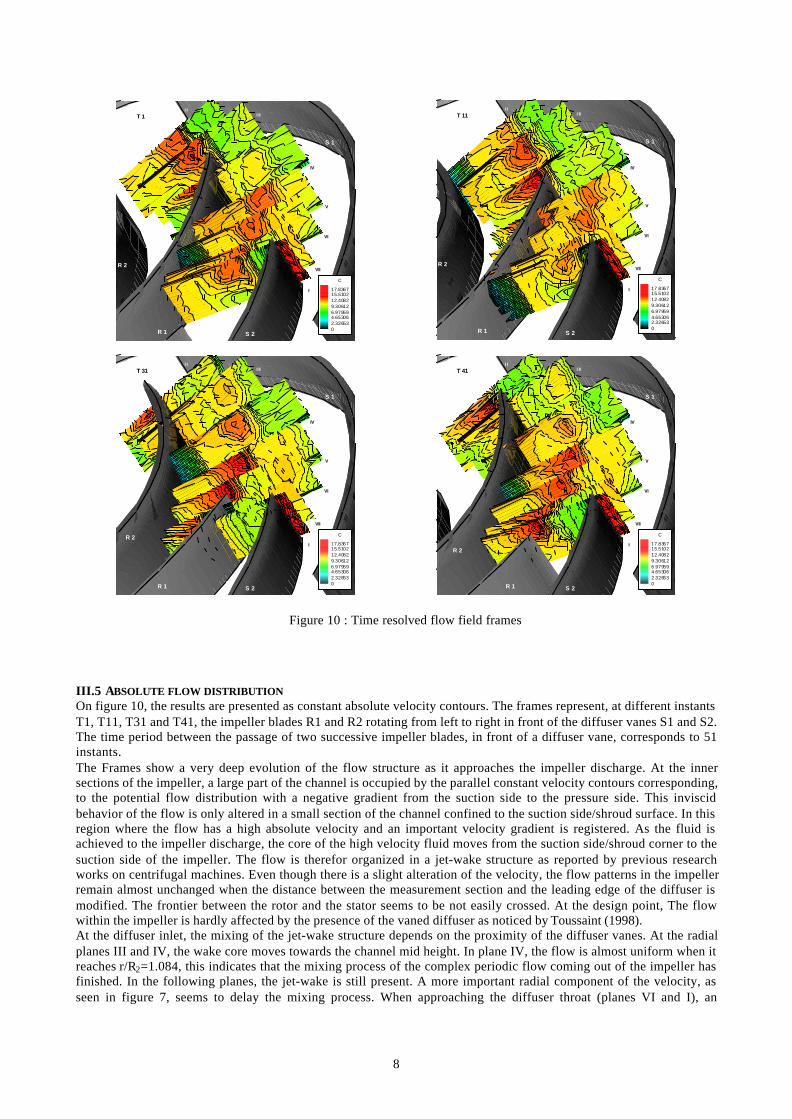
Figure 10 : Time resolved flow field frames
III.5 ABSOLUTE FLOW DISTRIBUTIONOn figure 10, the results are presented as constant absolute velocity contours. The frames represent, at different instantsT1, T11, T31 and T41, the impeller blades R1 and R2 rotating from left to right in front of the diffuser vanes S1 and S2.The time period between the passage of two successive impeller blades, in front of a diffuser vane, corresponds to 51instants.The Frames show a very deep evolution of the flow structure as it approaches the impeller discharge. At the innersections of the impeller, a large part of the channel is occupied by the parallel constant velocity contours corresponding,to the potential flow distribution with a negative gradient from the suction side to the pressure side. This inviscidbehavior of the flow is only altered in a small section of the channel confined to the suction side/shroud surface. In thisregion where the flow has a high absolute velocity and an important velocity gradient is registered. As the fluid isachieved to the impeller discharge, the core of the high velocity fluid moves from the suction side/shroud corner to thesuction side of the impeller. The flow is therefor organized in a jet-wake structure as reported by previous researchworks on centrifugal machines. Even though there is a slight alteration of the velocity, the flow patterns in the impellerremain almost unchanged when the distance between the measurement section and the leading edge of the diffuser ismodified. The frontier between the rotor and the stator seems to be not easily crossed. At the design point, The flowwithin the impeller is hardly affected by the presence of the vaned diffuser as noticed by Toussaint (1998).At the diffuser inlet, the mixing of the jet-wake structure depends on the proximity of the diffuser vanes. At the radialplanes III and IV, the wake core moves towards the channel mid height. In plane IV, the flow is almost uniform when itreaches r/R2=1.084, this indicates that the mixing process of the complex periodic flow coming out of the impeller hasfinished. In the following planes, the jet-wake is still present. A more important radial component of the velocity, asseen in figure 7, seems to delay the mixing process. When approaching the diffuser throat (planes VI and I), an
9
important velocity is registered on the pressure side of the vanes, the flow ruches to enter in the diffuser channels. In thesuction side, a flow slow down prevents the flow structure leaving the impeller to diffuse in the radial direction.
CONCLUSION
This detailed investigation of the internal flow within a centrifugal pump, at its design point, has permitted to study theeffect of a vaned diffuser on the flow inside the impeller. From the actual results, we can conclude that the impeller-diffuser interaction is limited to the impeller exit and it does not have any upstream influence on the flow. The frontierbetween the rotor and the stator seems to be not easily crossed. The mixing process of the flow at the impeller dischargeis affected by the presence of the diffuser vanes. The first half of the diffuser pitch is characterized by an early mixingof the flow. Whereas, in the second half, the flow entering the diffuser channel is still presenting its periodicity due tothe impeller. This results indicates, therefore, that the diffuser performances may be affected by the complex flowcoming out the impeller. Further investigations in the diffuser and at different operating conditions are projected tobetter understand the rotor-stator interaction.
REFERENCES
[1] N. Arndt, A. J. Acosta, C. E. Brennen, T. K. Caughey, Rotor-stator interaction in a diffuser pump, Journal ofTurbomachinery, 1989, Vol. 111, N° 3, p. 213-221.
[2] N. Arndt, A. J. Acosta, C. E. Brennen, T. K. Caughey, Experimental investigation of rotor-stator interaction in acentrifugal pump with several vaned diffusers, Journal of Turbomachinery, 1990, Vol. 112, N° 1, p. 98-108.
[3] A. Cattanei, D. Ottolio, M. Ubaldi, P. Zunino. "Unsteady Boundary Layers on the Blades of a Centrifugal StageDue to Rotor Blade Wake Interaction", 9th Intl. Symp. On Appl. Of Laser techniques to Fluid Mechanics , July 13-16, 1998 Lisbon, Portugal.
[4] D. Eckardt, Instantaneous Measurements in the Jet-Wake Discharge Flow of a Centrifugal Compressor Impeller,Journal of Engineering for Power, July 1975, p. 337-345.
[5] D. Eckardt, Detailed Flow Investigations within a High-Speed Centrifugal Compressor Impeller, Journal of FluidsEngineering, September 1976, p. 390-401.
[6] M. El Hajem, R. Morel, J.Y. Champagne, F. Spettel. "Centrifugal Impeller Flow Investigation", 1998 ASME FluidsEngineering Division Summer Meeting, June 21–25, 1998, Washington, DC.
[7] M. El Hajem, R. Morel, J.Y. Champagne, F. Spettel. " Detailed Measurements of the Internal Flow of a BacksweptCentrifugal Impeller", 9th Intl. Symp. On Appl. Of Laser techniques to Fluid Mechanics , July 13-16, 1998 Lisbon,Portugal.
[8] M. Inoue, N. A. Cumpsty, Experimental Study of Centrifugal Impeller Discharge Flow in Vaneless and VanedDiffusers, Journal of engineering for gas turbines and power, 1984, Vol. 106, N° 2, p. 455-467.
[9] J. P. Johnston, S. A. Eide, Turbulent Boundary Layers on Centrifugal Compressors Blades: Prediction of theEffects of Surface Curvature and Rotation, Journal of Fluids Engineering, September 1976, p. 374-381.
[10] M. W. Johnson, Secondary Flow in Rotating Bends. Journal of Engineering for Power, October 1978, Vol. 100, p.553-560.
[11] H. Krain, Swirling Impeller Flow, Journal of Turbomachinery, January 1988, Vol. 110, p. 122-128.[12] K. H. Rohne, M. Banzhaf, Investigation of the Flow at the exit of Unshrouded Centrifugal Impeller and
Comparison With the classical Jet-Wake Theory, Journal of Turbomachinery, October 1991, Vol. 113, p. 654-659.[13] C. H. Liu, C. Vafidis, J. H., Whitelaw, Flow characteristics of a centrifugal pump, Journal of fluids Engineering,
1994, Vol. 116, N° 2, p. 303-309.[14] S. M. Miner, R. J. Beaudoin, R. D. Flack, Laser velocimetery measurements in a centrifugal flow pump, Journal of
Turbomachinery, 1989, Vol. 111, N°3, p. 205-212.[15] M. Th.Sideris , R. A. Van DEN braembussche, Influence of a circumferential exit pressure distortion on the flow in
an impeller and diffuser, Journal of Turbomachinery, 1987, Vol. 109, N° 1, p. 48-54.[16] M. Toussaint , F. Hureau, J. F. Lapray, Influence des diffuseurs aubés sur le fonctionnement des pompes
centrifuges, La Houille Blanche n° 3/4, 1998, p. 38-44.[17] M. Ubaldi, P. Zunino, A. Cattanei, Relative Flow and Turbulence Measurements Downstream of a Backward
Centrifugal Impeller, Journal of Turbomachinery, July 1993, Vol. 115, p. 543-551.