Embed Size (px)
Citation preview
The Reluctance Motor Springs ForthDan Jones
There are three major types of reluctance motors: all three reluctance motors are non-permanent magnet, brushless motors. They are synchronous motors with a non-linear relationship between torque and current. The variable-reluctance step and switched-reluctance motors utilize the principle of magnetic attraction by inducing magnet poles within the soft-iron rotor, and by energizing a set of coils wound around stator teeth resident in the laminated stator. These two reluctance motors must be sequentially excited to achieve continuous, steady-state rotation. The design of all reluctance motors requires finite element analysis (FEA) software.
HistoryThe first reluctance motor was invented in 1838 to propel a lo-comotive. The mechanical switches used for sequentially en-ergizing the windings available at that time could only ener-gize the motor at very slow speeds. This switched-reluctance motor would have to await fast-switching electronic devices (e.g., transistors, FETs, IGBTs) that would become available in the 1970s to drive these motors.
The 1920s saw the development of variable-reluctance step motors in the U.K. for use in naval gun and navigation indica-tors. The emergence of the computer peripherals (printers, cash registers, and electronic typewriters) provided the ap-plication families for the thousands of variable-reluctance step motors in the 1970s and into the 1980s.
The emergence of the solid state devices at that time pro-vided for the creation and control of the switched reluctance (SR) motor. It possesses the same motor configuration as the variable reluctance step motor, but with a completely differ-ent drive and control electronics strategy. Hewlett-Packard’s draft master plotter was one of the early successes of SR mo-tors in the U.S. Switched Reluctance Drives Ltd (SRDL) — now part of Nidec-Emerson — played a key role in generating in-terest in Europe at that time.
The synchronous reluctance (SynRM) was initially devel-oped in the 1920s by J.K. Kosko. It too was unable to achieve its performance potential until the advent of high-performance power-and-control electronics used in variable speed drives (VSDs). A number of SynRM, axially laminated rotor designs executed in the 1970s coincided with the emergence of these electronic drives.
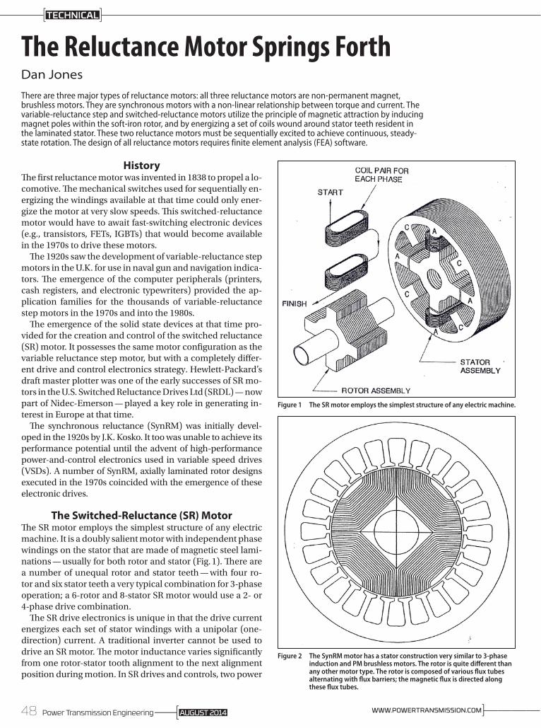
The Switched-Reluctance (SR) MotorThe SR motor employs the simplest structure of any electric machine. It is a doubly salient motor with independent phase windings on the stator that are made of magnetic steel lami-nations — usually for both rotor and stator (Fig. 1). There are a number of unequal rotor and stator teeth — with four ro-tor and six stator teeth a very typical combination for 3-phase operation; a 6-rotor and 8-stator SR motor would use a 2- or 4-phase drive combination.
The SR drive electronics is unique in that the drive current energizes each set of stator windings with a unipolar (one-direction) current. A traditional inverter cannot be used to drive an SR motor. The motor inductance varies significantly from one rotor-stator tooth alignment to the next alignment position during motion. In SR drives and controls, two power
Figure 1 The SR motor employs the simplest structure of any electric machine.
Figure 2 The SynRM motor has a stator construction very similar to 3-phase induction and PM brushless motors. The rotor is quite different than any other motor type. The rotor is composed of various flux tubes alternating with flux barriers; the magnetic flux is directed along these flux tubes.
48 Power Transmission Engineering ]————WWW.POWERTRANSMISSION.COMAUGUST 2014
TECHNICAL
devices per phase must be used to regulate the current mag-nitude and the waveform shape to achieve controlled opera-tion of the SR motor.
The Synchronous Reluctance Motor (SynRM)The emergence of the variable speed drive (VSD) brought the SynRM motor back into the limelight. It has the potential to exhibit a power efficiency higher than equivalent-sized AC induction motors. The various world governments’ em-phasis on higher power efficiency provided motor manufac-turers with a strong stimulus to evaluate this motor type.
The SynRM motor has a stator construction very similar to 3-phase induction and PM brushless motors. The rotor is quite different than any other motor type. The rotor is com-posed of various flux tubes alternating with flux barriers; the magnetic flux is directed along these flux tubes (Fig. 2). A typical number of poles is four or six. There are few rotor losses when the synchronous reluctance motor achieves synchronous speed. It operates on 3-phase sinusoidal voltage similar to an induction motor.
Today’s Application SuccessesThe ever increasing cost of rare earth mag-nets through the first decade of this centu-ry resulted in many motor manufacturers looking toward investigating both reluc-tance motor types for many cost-sensitive applications.
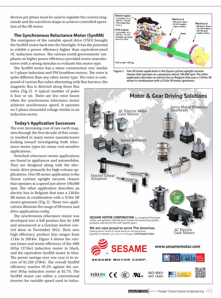
Switched-reluctance motor applications are found in appliances and automobiles. They are designed along with the elec-tronic drive primarily for high-volume ap-plications. One SR motor application is the Dyson cyclone upright vacuum cleaner that operates at a speed just above 100,000 rpm. The other application describes an electric bus in Belgium that uses a 130 Kw SR motor in combination with a 55 Kw SR motor-generator (Fig. 3). These two appli-cations illustrate the range of SR motor and drive applications today.
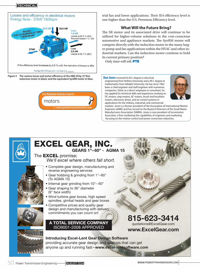
The synchronous reluctance motor was developed into a full product line by ABB and announced at a German motion con-trol show in November 2012. Their new high-efficiency product line ranges from 11 Kw to 200 Kw. Figure 4 shows the vari-ous losses and motor efficiency of the ABB 50 hp (37 Kw) induction motor in black, and the equivalent SynRM motor in blue. The power savings over one year is in ex-cess of $1,250 (Ɛ964). The overall SynRM efficiency reaches 95.3% against the cur-rent 50 hp induction motor at 92.7%. The SynRM motor can utilize a conventional inverter for variable speed used in indus-
GlobalGROUPISO 9001
MANAGEMENTSYSTEMS
U K A S
0039
®
GlobalGROUPISO 14001
MANAGEMENTSYSTEMS
U K A S
0039
®
BOOTH # E-4832
SESAME MOTOR CORPORATION is a leading Taiwanese motor and gearbox manufacturer known for producing quality products and service for over twenty years.
We are now proud to serve The Americas.Seeking North, Central & South American representatives.Qualified candidates can visit us in Chicago at IMTS Booth E-4832
Motor & Gear Driving Solutions
GlobalGROUPISO 9001
MANAGEMENTSYSTEMS
U K A S
0039
®
GlobalGROUPISO 14001
MANAGEMENTSYSTEMS
U K A S
0039
®
GlobalGROUPISO 9001
MANAGEMENTSYSTEMS
U K A S
0039
®
GlobalGROUPISO 14001
MANAGEMENTSYSTEMS
U K A S
0039
®
GlobalGROUPISO 9001
MANAGEMENTSYSTEMS
U K A S
0039
®
GlobalGROUPISO 14001
MANAGEMENTSYSTEMS
U K A S
0039
®
GlobalGROUPISO 9001
MANAGEMENTSYSTEMS
U K A S
0039
®
GlobalGROUPISO 14001
MANAGEMENTSYSTEMS
U K A S
0039
®
GlobalGROUPISO 9001
MANAGEMENTSYSTEMS
U K A S
0039
®
GlobalGROUPISO 14001
MANAGEMENTSYSTEMS
U K A S
0039
®
GlobalGROUPISO 9001
MANAGEMENTSYSTEMS
U K A S
0039
®
GlobalGROUPISO 14001
MANAGEMENTSYSTEMS
U K A S
0039
®
GlobalGROUPISO 9001
MANAGEMENTSYSTEMS
U K A S
0039
®
GlobalGROUPISO 14001
MANAGEMENTSYSTEMS
U K A S
0039
®
AC Electric MotorGear Motors
Speed Reducers
Electric Linear Actuators
Servo Motor Planetary Gearheads
AC Electric Gear Motors
www.sesamemotor.com
GlobalGROUPISO 9001
MANAGEMENTSYSTEMS
U K A S
0039
®
GlobalGROUPISO 14001
MANAGEMENTSYSTEMS
U K A S
0039
®
Figure 3 One SR motor application is the Dyson cyclone upright vacuum cleaner that operates at a speed just above 100,000 rpm. The other application describes an electric bus in Belgium that uses a 130 Kw SR motor in combination with a 55 Kw SR motor-generator.
49Power Transmission EngineeringAUGUST 2014
trial fan and lower applications. Their IE4 efficiency level is one higher than the U.S. Premium Efficiency level.
What Will the Future Bring?The SR motor and its associated drive will continue to be utilized for higher-volume solutions in the cost-conscious automotive and appliance markets. The SynRM motor will compete directly with the induction motor in the many larg-er pump and fan applications within the HVAC and other in-dustrial markets. Can the induction motor continue to hold its current primary position?
Only time will tell.
Figure 4 The various losses and motor efficiency of the ABB 50 hp (37 Kw) induction motor in black; and the equivalent SynRM motor in blue. Dan Jones received his B.S. degree in electrical
engineering from Hofstra University and a M.S. degree in mathematics from Adelphi University. He has since 1962 been a chief engineer and staff engineer with numerous companies. Either as a direct employee or consultant, he has applied his technical skills and experience working on DC motors, step motors, AC motors, brush and brushless motors, electronic drives, and on control systems in applications for the military, industrial, and commercial markets. Jones is a former president of the Association of International Motion Engineers (AIME) and has served on the Board of Directors of the Small Motor Manufacturers Association (SMMA). Jones is now president of Incremotion Associates, a firm combining the capabilities of engineers and marketing focusing on the motion control and power conversion industries.
www.ExcelGear.com
•Completegeardesign,manufacturingandreverseengineeringservices
•Gearhobbing&grindingfrom1"–60"(ToAGMA15)
•Internalgeargrindingfrom10"–60"•Gearshapingto36"diameter(9"facewidth)
•Windturbinegearboxes,highspeedspindles,gimbalheadsandgearboxes
•Competitivepricesandqualitygeardesignandmanufacturingwithdeliverycommitmentsyoucancounton!
EXCEL GEAR, INC.GEARS 1"– 60" - AGMA 15
TheEXCELpromise;We'll excel where others fall short.
Introducing Excel-Lent Gear Design Softwareprovidingaccurategeardesignandanalysisthatcangetanyoneupandrunningfast–www.excel-lentsoftware.com
A TOTAL SERVICE COMPANYISO9001-2008APPROVED
motors
For Related Articles Search
at www.powertransmission.com
50 Power Transmission Engineering ]————WWW.POWERTRANSMISSION.COMAUGUST 2014
TECHNICAL