Embed Size (px)
DESCRIPTION
The Serpentine Pavilion 2005 is a result of combination between the aesthetic of architecture, innovative engineering, and advanced digital technology. Pritzker Prize winners Alvaro Siza and Eduardo Souto de Moura and Cecil Balmond of internationally renowned structural engineering firm Arup, collaborated together in this annual project, which was commissioned by Serpentine Gallery. This paper will discuss how digital architecture and advanced manufacturing technique that were used in the Serpentine Pavilion 2005 realized the architectural intent. It will also look at how the engineering aspect could play an important role during design phase, even in the early design concept.
Citation preview
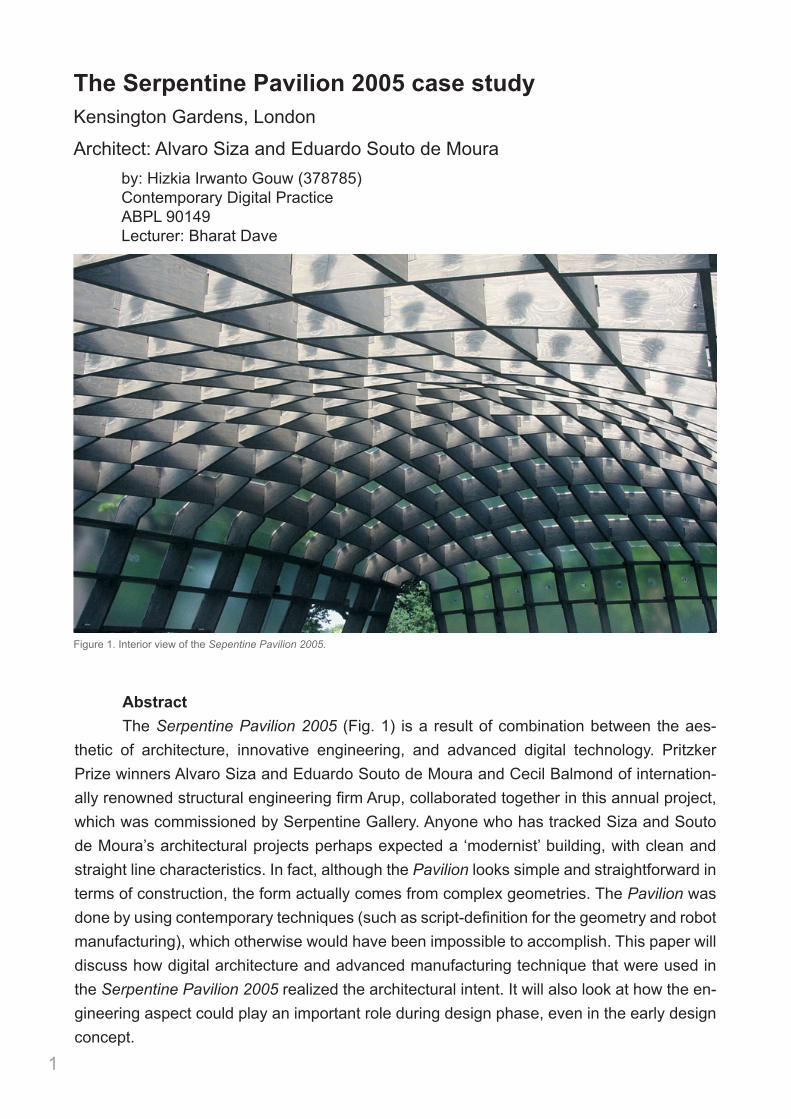
Abstract The Serpentine Pavilion 2005 (Fig. 1) is a result of combination between the aes-thetic of architecture, innovative engineering, and advanced digital technology. Pritzker Prize winners Alvaro Siza and Eduardo Souto de Moura and Cecil Balmond of internation-ally renowned structural engineering firm Arup, collaborated together in this annual project, which was commissioned by Serpentine Gallery. Anyone who has tracked Siza and Souto de Moura’s architectural projects perhaps expected a ‘modernist’ building, with clean and straight line characteristics. In fact, although the Pavilion looks simple and straightforward in terms of construction, the form actually comes from complex geometries. The Pavilion was done by using contemporary techniques (such as script-definition for the geometry and robot manufacturing), which otherwise would have been impossible to accomplish. This paper will discuss how digital architecture and advanced manufacturing technique that were used in the Serpentine Pavilion 2005 realized the architectural intent. It will also look at how the en-gineering aspect could play an important role during design phase, even in the early design concept.
1
The Serpentine Pavilion 2005 case studyKensington Gardens, London
Architect: Alvaro Siza and Eduardo Souto de Moura by: Hizkia Irwanto Gouw (378785) Contemporary Digital Practice ABPL 90149 Lecturer: Bharat Dave
Interior view of the Serpentine Pavilion designed by Álvaro Siza and EduardoSouto de Moura together with Cecil Balmond of Arup and Partners, London, 2005.
geometry of each element was digitally defined by Arup’sAdvanced Geometry Unit and mapped out in a format thatcould directly communicate with Finnforest Merk’s CAD/CAM
engineers. Using robot technology the required 427 uniquetimber beams could be manufactured within two weeks.Starting at one corner and radiating out to the opposite sides,the subsequent assembly process of the lattice also required aspecific protocol defining the only possible erection sequencefor the unique interlocking beams.
Today, with digital production and continuous datasetscomprising a practical approach rather than an idealised aim,the production of geometrically complex buildings andbuilding systems from differentiated components appears atangible, as well as feasible, proposition. Overall, the mostrelevant consideration for now is the relation betweenexisting skills and tools and emerging techniques andtechnologies. The work of the leading manufacturingcompanies suggests that the transfer and integration of CAM inthe field of construction requires the development of newproduction approaches in parallel with an understanding of
traditional means and skills. In fact, CAD/CAM technology maybecome a mechanism through which the potential of existingexpertise and methods is fully realised. The projects andprocesses that have been presented here indicate that thecritical moment of integrating existing and emergingmanufacturing techniques and technologies provides theinroad into an understanding of the yet uncovered potentialof new means of digital production. This moment of synthesisand synergy will be the vehicle for rethinking in the necessaryand latent redefinition of the construction process itself. 4
This article is based on an indepth research into the current possibilities and futureperspectives of fully integrated computer-aided design and manufacturing. As partof this exploration, Achim Menges and Michael Hensel visited specialistmanufacturing companies and their facilities in Germany to investigate anddiscuss the latest computer-controlled fabrication processes. Following this fieldtrip, the Emergence and Design Group organised the symposium entitled‘Manufacturing Diversity’, with representatives of the key companies at theArchitectural Association in February 2005. The article reports on the work andprojects presented by Dirk Emmer (Skyspan, Germany), Benoit Fauchon (Covertex,Germany), Michael Keller (Finnforest Merk, Germany), Thomas Spitzer (Seele,Germany) and Dr Karel Vollers representing Professor Mick Eekhout (Octatube, theNetherlands).
77
AD Morph. 070-077 1/6/06 3:34 pm Page 77
Figure 1. Interior view of the Sepentine Pavilion 2005.
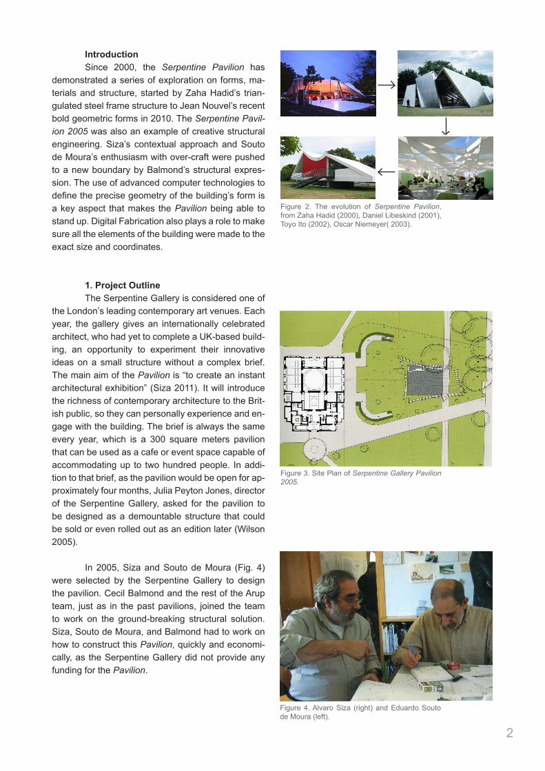
Introduction Since 2000, the Serpentine Pavilion has demonstrated a series of exploration on forms, ma-terials and structure, started by Zaha Hadid’s trian-gulated steel frame structure to Jean Nouvel’s recent bold geometric forms in 2010. The Serpentine Pavil-ion 2005 was also an example of creative structural engineering. Siza’s contextual approach and Souto de Moura’s enthusiasm with over-craft were pushed to a new boundary by Balmond’s structural expres-sion. The use of advanced computer technologies to define the precise geometry of the building’s form is a key aspect that makes the Pavilion being able to stand up. Digital Fabrication also plays a role to make sure all the elements of the building were made to the exact size and coordinates.
1. Project Outline The Serpentine Gallery is considered one of the London’s leading contemporary art venues. Each year, the gallery gives an internationally celebrated architect, who had yet to complete a UK-based build-ing, an opportunity to experiment their innovative ideas on a small structure without a complex brief. The main aim of the Pavilion is “to create an instant architectural exhibition” (Siza 2011). It will introduce the richness of contemporary architecture to the Brit-ish public, so they can personally experience and en-gage with the building. The brief is always the same every year, which is a 300 square meters pavilion that can be used as a cafe or event space capable of accommodating up to two hundred people. In addi-tion to that brief, as the pavilion would be open for ap-proximately four months, Julia Peyton Jones, director of the Serpentine Gallery, asked for the pavilion to be designed as a demountable structure that could be sold or even rolled out as an edition later (Wilson 2005).
In 2005, Siza and Souto de Moura (Fig. 4) were selected by the Serpentine Gallery to design the pavilion. Cecil Balmond and the rest of the Arup team, just as in the past pavilions, joined the team to work on the ground-breaking structural solution. Siza, Souto de Moura, and Balmond had to work on how to construct this Pavilion, quickly and economi-cally, as the Serpentine Gallery did not provide any funding for the Pavilion.
2
Figure 2. The evolution of Serpentine Pavilion, from Zaha Hadid (2000), Daniel Libeskind (2001), Toyo Ito (2002), Oscar Niemeyer( 2003).
Figure 3. Site Plan of Serpentine Gallery Pavilion 2005.
Figure 4. Alvaro Siza (right) and Eduardo Souto de Moura (left).
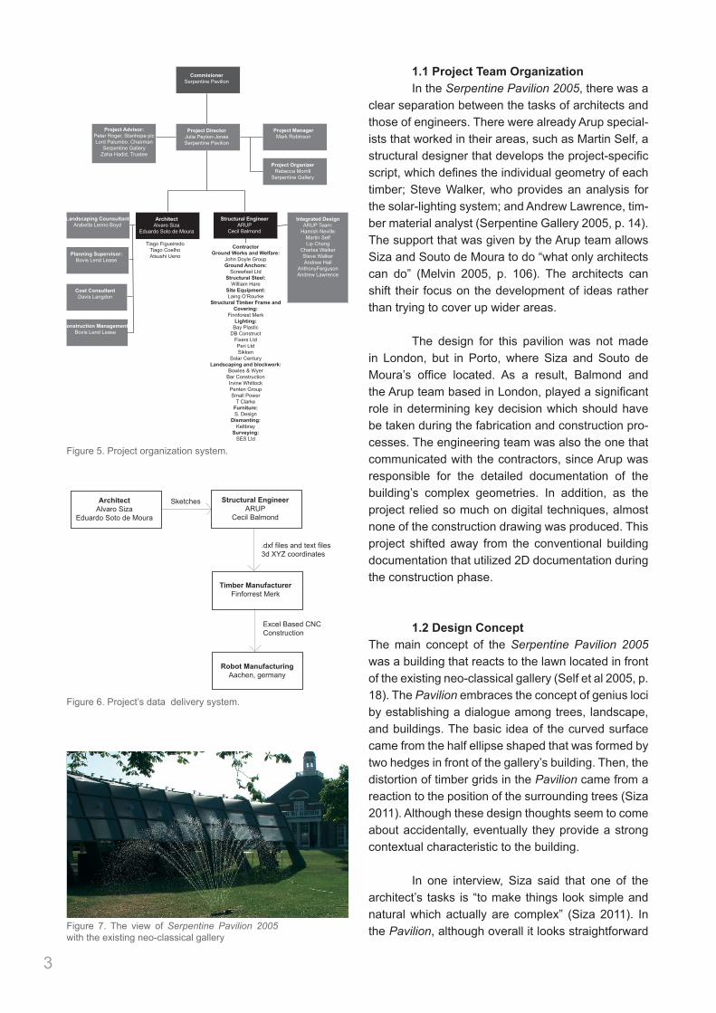
1.1 Project Team Organization In the Serpentine Pavilion 2005, there was a clear separation between the tasks of architects and those of engineers. There were already Arup special-ists that worked in their areas, such as Martin Self, a structural designer that develops the project-specific script, which defines the individual geometry of each timber; Steve Walker, who provides an analysis for the solar-lighting system; and Andrew Lawrence, tim-ber material analyst (Serpentine Gallery 2005, p. 14). The support that was given by the Arup team allows Siza and Souto de Moura to do “what only architects can do” (Melvin 2005, p. 106). The architects can shift their focus on the development of ideas rather than trying to cover up wider areas.
The design for this pavilion was not made in London, but in Porto, where Siza and Souto de Moura’s office located. As a result, Balmond and the Arup team based in London, played a significant role in determining key decision which should have be taken during the fabrication and construction pro-cesses. The engineering team was also the one that communicated with the contractors, since Arup was responsible for the detailed documentation of the building’s complex geometries. In addition, as the project relied so much on digital techniques, almost none of the construction drawing was produced. This project shifted away from the conventional building documentation that utilized 2D documentation during the construction phase.
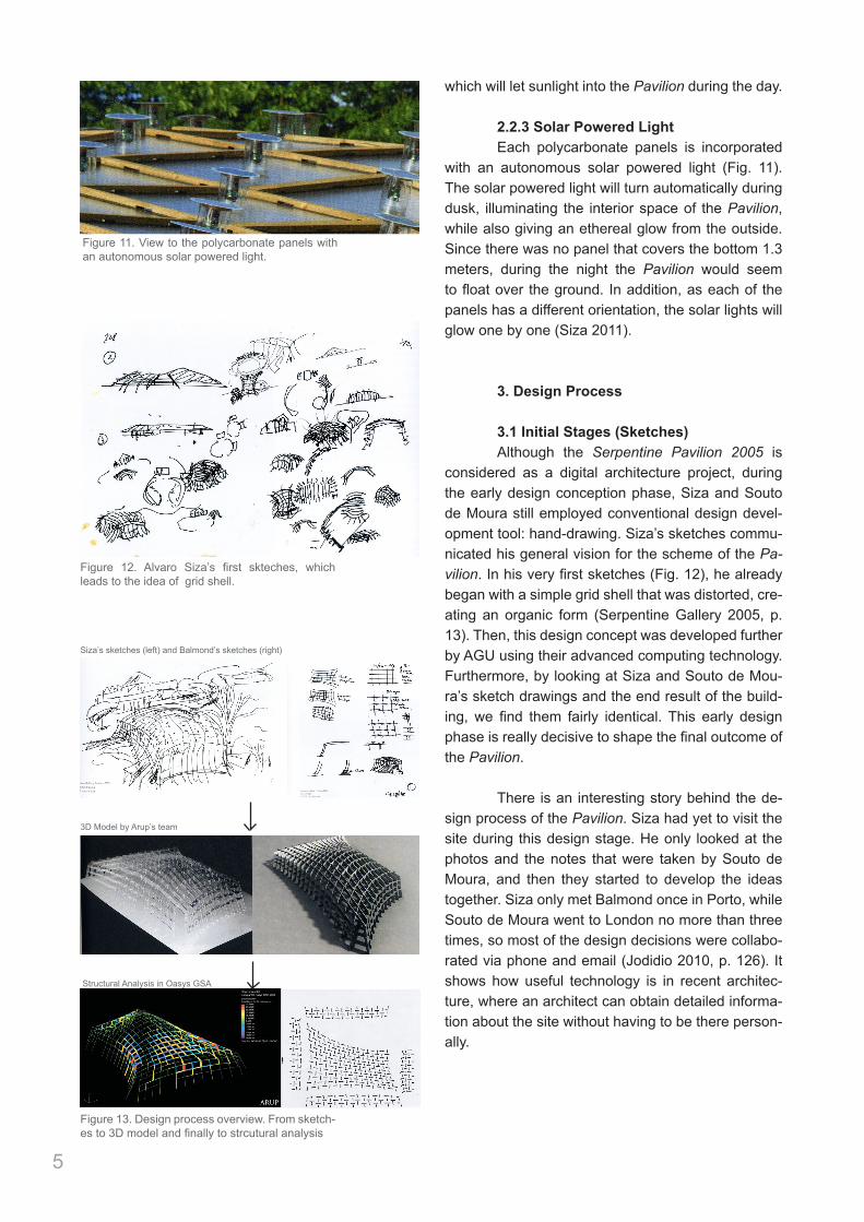
1.2 Design ConceptThe main concept of the Serpentine Pavilion 2005 was a building that reacts to the lawn located in front of the existing neo-classical gallery (Self et al 2005, p. 18). The Pavilion embraces the concept of genius loci by establishing a dialogue among trees, landscape, and buildings. The basic idea of the curved surface came from the half ellipse shaped that was formed by two hedges in front of the gallery’s building. Then, the distortion of timber grids in the Pavilion came from a reaction to the position of the surrounding trees (Siza 2011). Although these design thoughts seem to come about accidentally, eventually they provide a strong contextual characteristic to the building.
In one interview, Siza said that one of the architect’s tasks is “to make things look simple and natural which actually are complex” (Siza 2011). In the Pavilion, although overall it looks straightforward
3
6 September 2005 – The Structural Engineer|21
project: pavilion
ion the shear and moment stresses wereapproximately equally significant andcritical at the mortice and tenon joint.The reciprocal grillage is therefore lessefficient structurally but gives benefits inease of transport, erection and demount-ability.
FoundationsThe foundation system consisted of 18pairs of raked screw-piles arrangedaround the building perimeter, typicallyat every fourth column. To pick up theintermediate columns, a continuousburied steel RHS ground beam spans inbending and torsion between the screw-piles. Outrigger elements of steel channelprofiles connect the ground beam to thetops of the screw piles. The base Kertoelements have a bolted connection tosteel fin plates that are angled to thelocal inclination of the columns and arebolt connected via a baseplate to theground beam.
Fabrication and erectionThe pavilion’s Kerto structural memberswere fabricated at Finnforest Merk’sfacility at Aichach, near Munich. Eachmember was individually cut from largebillets of 69mm thick Kerto-Q, using arobotic arm normally used in car manu-facture. The robot is fully articulate in360º and can cut along 5 axes when usedwith the sliding cutting table. Therefore itwas able to cut each of the members tothe exact geometry required with noadditional cutting or shaping required toform, in particular, the top of the memberor the mortice-and-tenon connections.Each member was then referencelabelled, preservative treated, stainedand packed onto pallets.
The Kerto members were delivered tothe Serpentine site by lorry and palletswere unloaded by tele-handler. Thepallets had been packed in Aichach tosuit the anticipated erection sequenceand each member was labelled with theunique structural grid reference for thatmember. The Kerto elements were passedindividually to two operatives in a scissorlift to locate each member in the struc-
ture. A third operative in a cherry pickerfollowed the erection sequence, locatedand drilled a hole through the mortice-and-tenon and then fixed the single loca-tion bolt that was used at each node tohelp hold the structure in position duringthe erection process.
As these node connections werecompleted a vertical and horizontallyadjustable prop was fixed under the nodepoint to support the temporarily freeunsupported end of the member and holdthe structure in position during erection.Once each ‘arched rib’ of the structurewas complete the node points weresurveyed and the props adjusted for bothheight and alignment to ensure that thestructure was kept within a strict erec-tion tolerance of + or – 5mm at everystage of the erection. Once the structurewas complete the temporary erectionprops were removed.
ConclusionErection was complete by the end of May2005, less than 4 months after the firstmeeting about the structure. Despite thisvery fast programme, all but one of the
427 elements fitted perfectly on site. Thiswould have been impossible withoutusing script-definition for the geometryand direct transfer of digital data to fabri-cator. These contemporary techniquesproduced an innovative structure thatrealised the architectural intent.
• The authors will talk about thePavilion in more detail at a presentationhosted by the wood. for good campaign onthe 15 September at the Pavilion; seewebsite: (www.woodforgood.com/events/bww_events_timetable.html).
se
KERTO is a laminated veneered lumber and is a veryenvironmentally friendly wood product, made from Finnishspruce. It is produced by rotary peeling the spruce logs into3mm thick veneers which are then glued together, using a WBP-type glue, to form a continuous billet up to 2.4m wide by 25mlong in 6mm incremental thicknesses from 21 to 75mm. Thebillet is hot pressed to expedite the gluing process andcompletes the production of the Kerto billet.
Kerto’s excellent structural and dimensional properties made ita very good choice for use as the load-bearing elements of thepavilion structure. It derives these properties from the nature ofthe homogeneous veneered structure, which also keeps theeffects of any defective single veneers down to a minimum. Ittherefore produces a structural timber product that isapproximately 100% more structurally efficient than theequivalent volume of spruce softwood, in effect producing astructural member that would have to be twice as large, if it wasfabricated out of solid spruce softwood.
WHAT IS KERTO?Pavilion underconstruction
The finishedstructure(editorial photo)
CommisionerSerpentine Pavilion
Project DirectorJulia Peyton-JonesSerpentine Pavilion
ArchitectAlvaro Siza
Eduardo Soto de Moura
Structural EngineerARUP
Cecil Balmond
Integrated DesignARUP Team:
Hamish NevilleMartin SelfLip Chong
Charles WalkerSteve WalkerAndrew Hall
AnthonyFergusonAndrew Lawrence
Project ManagerMark Robinson
Landscaping CounsultantArabella Lenno Boyd
ContractorGround Works and Welfare:
John Doyle GroupGround Anchors:
Screwfast LtdStructural Steel:
William HareSite Equipment:Laing O’Rourke
Structural Timber Frame and Covering:
Finnforest MerkLighting:
Bay PlasticDB Construct
Fixers LtdPeri LtdSikken
Solar CenturyLandscaping and blockwork:
Bowles & WyerBar ConstructionIrvine WhitlockPenten GroupSmall Power
T ClarkeFurniture:S. Design
Dismanting:Keltbray
Surveying:SES Ltd
Project Advisor:Peter Roger, Stanhope plcLord Palumbo, Chairman
Serpentine GalleryZaha Hadid, Trustee
Project OrganizerRebecca Morrill
Serpentine Gallery
Cost ConsultantDavis Langdon
Planning Supervisor:Bovis Lend Lease
Construction ManagementBovis Lend Lease
Tiago FigueiredoTiago CoelhoAtsushi Ueno
Figure 5. Project organization system.
Figure 7. The view of Serpentine Pavilion 2005 with the existing neo-classical gallery
ArchitectAlvaro Siza
Eduardo Soto de Moura
Structural EngineerARUP
Cecil Balmond
Timber ManufacturerFinforrest Merk
Robot ManufacturingAachen, germany
Sketches
.dxf files and text files 3d XYZ coordinates
Excel Based CNC Construction
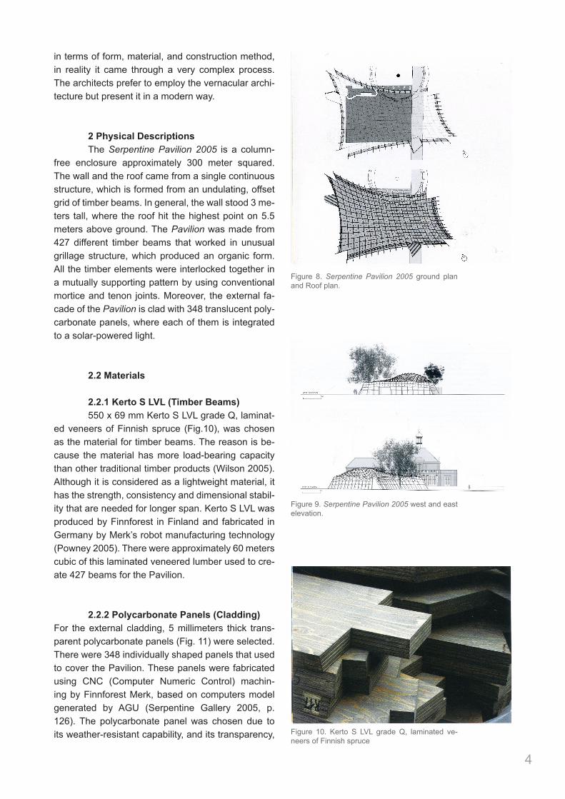
Figure 6. Project’s data delivery system.
in terms of form, material, and construction method, in reality it came through a very complex process. The architects prefer to employ the vernacular archi-tecture but present it in a modern way.
2 Physical Descriptions The Serpentine Pavilion 2005 is a column-free enclosure approximately 300 meter squared. The wall and the roof came from a single continuous structure, which is formed from an undulating, offset grid of timber beams. In general, the wall stood 3 me-ters tall, where the roof hit the highest point on 5.5 meters above ground. The Pavilion was made from 427 different timber beams that worked in unusual grillage structure, which produced an organic form. All the timber elements were interlocked together in a mutually supporting pattern by using conventional mortice and tenon joints. Moreover, the external fa-cade of the Pavilion is clad with 348 translucent poly-carbonate panels, where each of them is integrated to a solar-powered light.
2.2 Materials
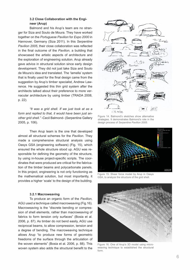
2.2.1 Kerto S LVL (Timber Beams) 550 x 69 mm Kerto S LVL grade Q, laminat-ed veneers of Finnish spruce (Fig.10), was chosen as the material for timber beams. The reason is be-cause the material has more load-bearing capacity than other traditional timber products (Wilson 2005). Although it is considered as a lightweight material, it has the strength, consistency and dimensional stabil-ity that are needed for longer span. Kerto S LVL was produced by Finnforest in Finland and fabricated in Germany by Merk’s robot manufacturing technology (Powney 2005). There were approximately 60 meters cubic of this laminated veneered lumber used to cre-ate 427 beams for the Pavilion.
2.2.2 Polycarbonate Panels (Cladding)For the external cladding, 5 millimeters thick trans-parent polycarbonate panels (Fig. 11) were selected. There were 348 individually shaped panels that used to cover the Pavilion. These panels were fabricated using CNC (Computer Numeric Control) machin-ing by Finnforest Merk, based on computers model generated by AGU (Serpentine Gallery 2005, p. 126). The polycarbonate panel was chosen due to its weather-resistant capability, and its transparency,
4
Figure 8. Serpentine Pavilion 2005 ground plan and Roof plan.
Figure 9. Serpentine Pavilion 2005 west and east elevation.
Figure 10. Kerto S LVL grade Q, laminated ve-neers of Finnish spruce
which will let sunlight into the Pavilion during the day.
2.2.3 Solar Powered Light Each polycarbonate panels is incorporated with an autonomous solar powered light (Fig. 11). The solar powered light will turn automatically during dusk, illuminating the interior space of the Pavilion, while also giving an ethereal glow from the outside. Since there was no panel that covers the bottom 1.3 meters, during the night the Pavilion would seem to float over the ground. In addition, as each of the panels has a different orientation, the solar lights will glow one by one (Siza 2011).
3. Design Process
3.1 Initial Stages (Sketches) Although the Serpentine Pavilion 2005 is considered as a digital architecture project, during the early design conception phase, Siza and Souto de Moura still employed conventional design devel-opment tool: hand-drawing. Siza’s sketches commu-nicated his general vision for the scheme of the Pa-vilion. In his very first sketches (Fig. 12), he already began with a simple grid shell that was distorted, cre-ating an organic form (Serpentine Gallery 2005, p. 13). Then, this design concept was developed further by AGU using their advanced computing technology. Furthermore, by looking at Siza and Souto de Mou-ra’s sketch drawings and the end result of the build-ing, we find them fairly identical. This early design phase is really decisive to shape the final outcome of the Pavilion.
There is an interesting story behind the de-sign process of the Pavilion. Siza had yet to visit the site during this design stage. He only looked at the photos and the notes that were taken by Souto de Moura, and then they started to develop the ideas together. Siza only met Balmond once in Porto, while Souto de Moura went to London no more than three times, so most of the design decisions were collabo-rated via phone and email (Jodidio 2010, p. 126). It shows how useful technology is in recent architec-ture, where an architect can obtain detailed informa-tion about the site without having to be there person-ally.
5
Figure 11. View to the polycarbonate panels with an autonomous solar powered light.
Figure 12. Alvaro Siza’s first skteches, which leads to the idea of grid shell.
18|The Structural Engineer – 6 September 2005
project: pavilion
The Serpentine Gallery’s programmeof summer pavilions provides anannual laboratory for architectural
and engineering experimentation. Since2000, the pavilions at the London galleryhave tested a series of forms and materi-als – for example the sculpturalaluminium stress-skin structure byDaniel Libeskind, and the algorithm-generated steel box by Toyo Ito with CecilBalmond.
Julia Peyton-Jones, the gallery's direc-tor, maintains a curatorial approach toinviting and exhibiting the architects.She approached this year’s architects,Portugal’s Álvaro Siza and EduardoSouto De Moura, in December 2004.
As in previous years, Arup’s CecilBalmond collaborated with the architectsin a design role, and the AdvancedGeometry Unit (AGU) at Arup realisedthe geometric and engineering design ofthe pavilion. Finnforest Merk producedand fabricated the timber material,provided specialist advice to Arup indesigning the structure, and coordinatedits construction.
The architectural concept was for abuilding that responded to its location onthe lawn in front of the existing neo-clas-sical gallery. A timber grid was proposed,distorted in reaction to the gallery build-ing, surrounding trees and landscape.
The resulting pavilion is a column-freeenclosure approximately 25m × 15m inplan. The walls are typically 3m tall andthe roof reaches a maximum height of5.5m above ground in the domed middlesection. The geometry is based on aquadrilateral plan and has wall and roofcurvatures defined by arcs in plan andelevation respectively. The pavilion is cladexternally with 248 translucent 5mmthick polycarbonate panels each incorpo-
rating an autonomous solar-poweredlight.
Lamella structureThe initial concept of a timber gridassumed, by default, continuously span-ning members. However, this strategywould have led to an unwanted hierarchy(primary and secondary spanning direc-tions), with the scale and geometry prob-ably requiring compromising splicedetails in the members. At the earlydesign sessions, the potential for a hand-crafted vernacular style of timberconstruction was discussed, and theconcept of a contemporary structureemploying a traditional constructionlanguage was proposed.
A solution with exciting potentialbecame apparent through a developmentof lamella roof structures. Here, short,pin-ended, members are arranged tobuild up a structural lattice with a grid-length of one-half of the member lengths,resulting in a stable system. The inter-locking members are arranged in a mutu-ally supporting pattern, allowing eachindividual element to have simplemortice-and-tenon connections, yet ableto maintain the overall bending stiffnessof the frame.
Traditional lamella roofs, for examplethose built by Zollinger in Germany inthe 1920s, are assembled from identicalelements and used to build barrel-vaulttype structures, with in-plane forces. Thesame structural arrangement can beused to form a grillage, in which the out-of-plane force in each element is trans-ferred in shear to the mid-point of thetwo neighbouring elements, building up acomplex looping load-path.
For the pavilion, this reciprocal grillagesystem was advanced to allow a
completely free-form geometry to be built.To achieve this, every element is uniqueand varies in length and inclination. Thestructural action becomes a combinationof arch (compressive) and grillage(bending) behaviours.
In the roof, the elements are alloriented with their major-dimensionvertical. The walls use a similar system,but with elements oriented horizontally.Because the system can accommodatedirection change in the grid, the struc-tural pattern is uninterrupted across theeaves. For example, two-bay elements‘fold’ over the eaves giving one roof bayand one wall bay.
The connection between elements is asimple mortice and tenon connection, inwhich two tenons from adjoiningelements connect into the mortice at thecentre of the cross-element. To allow thetwo tenons to fit side by side, eachelement is alternately offset from the gridcentreline by half the element thickness.
Serpentine PavilionThis year’s pavilion in Kensington Gardens,London, was a timber design challenge. MartinSelf (Arup) and Jonathan Stone (M), FinnforestMerk, describe the process
The Pavilion’sdistorted timbergrid (All photosunless marked tothe contrary arecourtesy of Arup)
Below left:moment forces3D modelBelow: shearforces 3D model
Figure 13. Design process overview. From sketch-es to 3D model and finally to strcutural analysis
Siza’s sketches (left) and Balmond’s sketches (right)
3D Model by Arup’s team
Structural Analysis in Oasys GSA
3.2 Close Collaboration with the Engi- neer (Arup) Balmond and his Arup’s team are no stran-ger for Siza and Souto de Moura. They have worked together on the Portuguese Pavilion for Expo 2000 in Hannover, Germany (Siza 2011). In this Serpentine Pavilion 2005, their close collaboration was reflected in the final outcome of the Pavilion, a building that showcased the artistic aspects of architecture and the exploration of engineering solution. Arup already gave advice in structural solution since early design development. They did not just take Siza and Souto de Moura’s idea and translated. The ‘lamella’ system that is finally used for the final design came from the suggestion by Arup’s timber specialist, Andrew Law-rence. He suggested this thin grid system after the architects talked about their preference to more ver-nacular architecture by using timber (TRADA 2008, p. 22).
“It was a grid shell. If we just took at as a form and replied to that, it would have been just an-other grid shell.” -Cecil Balmond- (Serpentine Gallery 2005, p. 106).
Then Arup team is the one that developed almost all structural schemes for the Pavilion. They made a comprehensive structural analysis using Oasys GSA (engineering software) (Fig. 15), which ensured the whole structure stood up. AGU was re-sponsible for defining the geometry of the structure, by using in-house project-specific scripts. The coor-dinates that were produced are critical for the fabrica-tion of the timber beams and polycarbonate panels. In this project, engineering is not only functioning as the mathematical solution, but most importantly, it provides a higher ‘scale’ to the design of the building.
3.2.1 Macroweaving To produce an organic form of the Pavilion, AGU used a technique called macroweaving (Fig.16). Macroweaving is the “discrete bending or compres-sion of shell elements, rather than macroweaving of fabrics to form tension only surfaces” (Bosia et al. 2006, p. 87). As timber do not bend easily, AGU use reciprocal beams, to allow compression, tension and a degree of bending. The macroweaving technique allows Arup “to produce new forms of geometric freedoms of the surface through the articulation of the woven elements” (Bosia et al. 2006, p. 88). This woven system also adds the structural benefit to the
6
18|The Structural Engineer – 6 September 2005
project: pavilion
The Serpentine Gallery’s programmeof summer pavilions provides anannual laboratory for architectural
and engineering experimentation. Since2000, the pavilions at the London galleryhave tested a series of forms and materi-als – for example the sculpturalaluminium stress-skin structure byDaniel Libeskind, and the algorithm-generated steel box by Toyo Ito with CecilBalmond.
Julia Peyton-Jones, the gallery's direc-tor, maintains a curatorial approach toinviting and exhibiting the architects.She approached this year’s architects,Portugal’s Álvaro Siza and EduardoSouto De Moura, in December 2004.
As in previous years, Arup’s CecilBalmond collaborated with the architectsin a design role, and the AdvancedGeometry Unit (AGU) at Arup realisedthe geometric and engineering design ofthe pavilion. Finnforest Merk producedand fabricated the timber material,provided specialist advice to Arup indesigning the structure, and coordinatedits construction.
The architectural concept was for abuilding that responded to its location onthe lawn in front of the existing neo-clas-sical gallery. A timber grid was proposed,distorted in reaction to the gallery build-ing, surrounding trees and landscape.
The resulting pavilion is a column-freeenclosure approximately 25m × 15m inplan. The walls are typically 3m tall andthe roof reaches a maximum height of5.5m above ground in the domed middlesection. The geometry is based on aquadrilateral plan and has wall and roofcurvatures defined by arcs in plan andelevation respectively. The pavilion is cladexternally with 248 translucent 5mmthick polycarbonate panels each incorpo-
rating an autonomous solar-poweredlight.
Lamella structureThe initial concept of a timber gridassumed, by default, continuously span-ning members. However, this strategywould have led to an unwanted hierarchy(primary and secondary spanning direc-tions), with the scale and geometry prob-ably requiring compromising splicedetails in the members. At the earlydesign sessions, the potential for a hand-crafted vernacular style of timberconstruction was discussed, and theconcept of a contemporary structureemploying a traditional constructionlanguage was proposed.
A solution with exciting potentialbecame apparent through a developmentof lamella roof structures. Here, short,pin-ended, members are arranged tobuild up a structural lattice with a grid-length of one-half of the member lengths,resulting in a stable system. The inter-locking members are arranged in a mutu-ally supporting pattern, allowing eachindividual element to have simplemortice-and-tenon connections, yet ableto maintain the overall bending stiffnessof the frame.
Traditional lamella roofs, for examplethose built by Zollinger in Germany inthe 1920s, are assembled from identicalelements and used to build barrel-vaulttype structures, with in-plane forces. Thesame structural arrangement can beused to form a grillage, in which the out-of-plane force in each element is trans-ferred in shear to the mid-point of thetwo neighbouring elements, building up acomplex looping load-path.
For the pavilion, this reciprocal grillagesystem was advanced to allow a
completely free-form geometry to be built.To achieve this, every element is uniqueand varies in length and inclination. Thestructural action becomes a combinationof arch (compressive) and grillage(bending) behaviours.
In the roof, the elements are alloriented with their major-dimensionvertical. The walls use a similar system,but with elements oriented horizontally.Because the system can accommodatedirection change in the grid, the struc-tural pattern is uninterrupted across theeaves. For example, two-bay elements‘fold’ over the eaves giving one roof bayand one wall bay.
The connection between elements is asimple mortice and tenon connection, inwhich two tenons from adjoiningelements connect into the mortice at thecentre of the cross-element. To allow thetwo tenons to fit side by side, eachelement is alternately offset from the gridcentreline by half the element thickness.
Serpentine PavilionThis year’s pavilion in Kensington Gardens,London, was a timber design challenge. MartinSelf (Arup) and Jonathan Stone (M), FinnforestMerk, describe the process
The Pavilion’sdistorted timbergrid (All photosunless marked tothe contrary arecourtesy of Arup)
Below left:moment forces3D modelBelow: shearforces 3D model
Figure 14. Balmond’s sketches show alternative strategies. It demonstrates Balmond’s role in the design process of Serpentine Pavilion 2005.
Figure 15. Shear force model by Arup in Oasys GSA, to analyze the structure of the grid shell.
Figure 16. One of Arup’s 3D model using micro-weaving technique to established the structural form.
hours after sundown. The timber members fit together by thevery traditional means of mortice and tenon joints, and theperfection of their fit means that steel bolts are unnecessary –though they were apparently useful during erection. As Sizasays: ‘Everything new has a lot of history in it.’
Technically, explains Balmond, the structure is a reciprocalshell, where every structural member ‘lives’ off those towhich it connects, and these interconnections are vital forstability. The visual effect is arresting as, rather than thestraight and smooth lines much loved by architects likeFoster, the ribs seem to wander around, not quite aligned butnonetheless describing an overall homogeneous form. Thereis perhaps a trite analogy between the indirect connectionsbetween elements and Siza’s interpretation of the influences,though the effect is certainly a sense of unity throughcomplexity. Balmond refers to a shared interest in ArtePovera, using the most basic materials and apparently simpletechniques to create a richness of expression through
intellect. Siza and Souto de Moura speak of an interestin the vernacular, but also of how their perceptions of the environment where both grew up in northernPortugal were infused with ideas from outside. Siza,the senior by almost 20 years, specifically cites theinfluence of Architecture d’Aujourdhui. Infusing thevernacular with an intellectual sophistication –whether developed through drawing, computerprograms or both – until it ceases to be vernacular is a hallmark of both architects’ work.
This small project indicates a much wider spread ofgeography and history. The timber comes from Finlandand was fabricated in Germany. Design work took placeon an axis between London and Oporto, where botharchitects are based – when not working in Barcelona(Souto de Moura) or a vast 200,000-square-metrehospital in Toledo, Spain (Siza), as well as furtherafield. But such connections are not new, especially to
105 +
Top leftPlanometric view, showing the pavilion form and existing gallery, and the manipulation of the precinct between them.
Bottom leftOne of Arup’s models developed to establish the structural form.
Top rightEach piece of timber is different.
Bottom rightDiagram showing the relationship between each piece of timber and how they join to make a structure.
+
pavilion, due to the mutually supporting pattern (inter-locking system) between each member.
3.2 Digital Fabrication
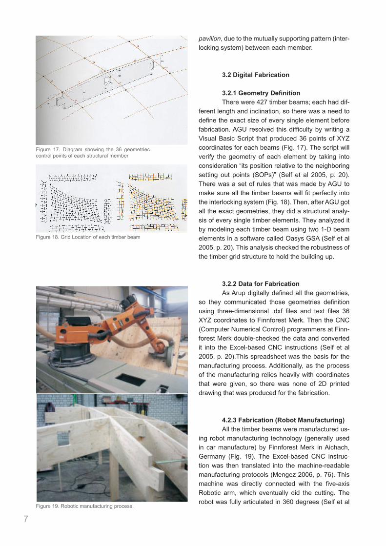
3.2.1GeometryDefinition There were 427 timber beams; each had dif-ferent length and inclination, so there was a need to define the exact size of every single element before fabrication. AGU resolved this difficulty by writing a Visual Basic Script that produced 36 points of XYZ coordinates for each beams (Fig. 17). The script will verify the geometry of each element by taking into consideration “its position relative to the neighboring setting out points (SOPs)” (Self et al 2005, p. 20). There was a set of rules that was made by AGU to make sure all the timber beams will fit perfectly into the interlocking system (Fig. 18). Then, after AGU got all the exact geometries, they did a structural analy-sis of every single timber elements. They analyzed it by modeling each timber beam using two 1-D beam elements in a software called Oasys GSA (Self et al 2005, p. 20). This analysis checked the robustness of the timber grid structure to hold the building up.
3.2.2 Data for Fabrication As Arup digitally defined all the geometries, so they communicated those geometries definition using three-dimensional .dxf files and text files 36 XYZ coordinates to Finnforest Merk. Then the CNC (Computer Numerical Control) programmers at Finn-forest Merk double-checked the data and converted it into the Excel-based CNC instructions (Self et al 2005, p. 20).This spreadsheet was the basis for the manufacturing process. Additionally, as the process of the manufacturing relies heavily with coordinates that were given, so there was none of 2D printed drawing that was produced for the fabrication.
4.2.3 Fabrication (Robot Manufacturing) All the timber beams were manufactured us-ing robot manufacturing technology (generally used in car manufacture) by Finnforest Merk in Aichach, Germany (Fig. 19). The Excel-based CNC instruc-tion was then translated into the machine-readable manufacturing protocols (Mengez 2006, p. 76). This machine was directly connected with the five-axis Robotic arm, which eventually did the cutting. The robot was fully articulated in 360 degrees (Self et al
7
Finnforest Merk 3-D curved timbertracks. Basic gluelam arches (left)prepared for subsequent roboticmilling (centre); finished 3-D curvedtimber tracks installed on a woodenrollercoaster in Soltau, Germany (right).
These CAM facilities, combined with sophisticated solidmodelling CAD applications, allow for consistent engineeringand fabrication datasets that have enabled Seele to contributeto the production of highly complex buildings such as theSeattle Central Library designed by OMA. In this project, Seelewas responsible for the cladding preconstruction services, theproduction and installation of the 11,900 square metres(128,000 square feet) of exterior cladding comprising morethan 6500 glass panels and 30,000 anodised aluminiumprofiles. The building’s faceted skin geometry requiredextensive 3-D engineering as the facade surfaces ofaluminium extrusions, silicone gaskets, triple-glazing panels,pressure plates, gutters and closing panels join in up to fivedifferent angles at particular node points. A comprehensivedigital 3-D solid model of the entire facade provided themanufacturing data for all prefabricated elements as well asthe related labelling information, packing lists andtransportation schedules.
The digital model also allowed for adjusting the productionand installation of the facade system to tolerances in theprimary steelwork of up to 2.5 centimetres (1 inch) occurringafter the actual erection. For these adjustments a digitalscanning process notates clusters of measure points of thealready built primary structure in relation to fixed referencepoints. The resulting 3-D point cloud allows for digitallyoverlapping the primary system as built with the digital modelof the facade as designed. The identified deviations can then becompensated for in the manufacturing and installation of thecladding elements on site.
Finnforest Merk: Robotic Timber ManufacturingMost of the CAM processes described thus far requirespecialised machines that can perform specific manufacturingtasks such as milling, cutting, welding and so on. However, ina few cases the more versatile machines used, for instance, inthe automotive industry are beginning to be employed in thebuilding industry. An interesting example of this development
is the use of a robotic manufacturing unit by German timberconstruction company Finnforest Merk. Equipped withdifferent tool heads and driven by the appropriate software,such a basic manufacturing robot can execute diversemanufacturing processes ranging from welding of sheet metalto cutting and sewing of composite reinforcement.Furthermore, such robots can automatically identify theposition and type of workpiece to be machined, perform anentire sequence of fabrication steps by automaticallychanging tool heads, and later on check the result foraccuracy and tolerances.
Equipping such a basic robotic unit for timbermanufacturing has enabled Finnforest Merk to produce bothcomplex single building elements and geometrically complexconstructions made from a large number of differentcomponents. A typical case for the fabrication of complexbuilding elements is the 3-D curved timber tracks Merkproduced for a wooden rollercoaster located in Soltau inGermany. For this project, Merk combined its long-establishedexpertise in producing gluelam arches with the machiningpotential of its five-axis robot equipped with a milling tooland the ability of its CAD/CAM engineers to translate therelevant data into machine-readable manufacturing protocols.The high strength required by cars travelling at 120kilometres (75 miles) per hour and forces of up to 4g, as wellas the complex curvature of the tracks, was achieved byrobotically machining gluelam arches curved in one planeinto 3-D curved beams.
In another project, the 2005 Serpentine Pavilion designedby Álvaro Siza and Eduardo Souto de Moura together withCecil Balmond of Arup and Partners, the main challenge forMerk has been the construction of a complex structure from alarge number of unique components. The pavilion’s 17-metre(56-foot) clear spanning curved roof and walls are articulatedas an undulating offset grid of laminated timber. The latticeelements are arranged in mutually supporting patterns andjoined by mortice-and-tenon connections. The unique
76
Finnforest Merk Serpentine Paviliontimber structure. Robotic manufacturingof timber elements (left); mock-up oflattice elements joined by mortice-and-tenon connections (centre); installationof timber structure onsite in London(right).
AD Morph. 070-077 1/6/06 3:34 pm Page 76
Figure 19. Robotic manufacturing process.
Finnforest Merk 3-D curved timbertracks. Basic gluelam arches (left)prepared for subsequent roboticmilling (centre); finished 3-D curvedtimber tracks installed on a woodenrollercoaster in Soltau, Germany (right).
These CAM facilities, combined with sophisticated solidmodelling CAD applications, allow for consistent engineeringand fabrication datasets that have enabled Seele to contributeto the production of highly complex buildings such as theSeattle Central Library designed by OMA. In this project, Seelewas responsible for the cladding preconstruction services, theproduction and installation of the 11,900 square metres(128,000 square feet) of exterior cladding comprising morethan 6500 glass panels and 30,000 anodised aluminiumprofiles. The building’s faceted skin geometry requiredextensive 3-D engineering as the facade surfaces ofaluminium extrusions, silicone gaskets, triple-glazing panels,pressure plates, gutters and closing panels join in up to fivedifferent angles at particular node points. A comprehensivedigital 3-D solid model of the entire facade provided themanufacturing data for all prefabricated elements as well asthe related labelling information, packing lists andtransportation schedules.
The digital model also allowed for adjusting the productionand installation of the facade system to tolerances in theprimary steelwork of up to 2.5 centimetres (1 inch) occurringafter the actual erection. For these adjustments a digitalscanning process notates clusters of measure points of thealready built primary structure in relation to fixed referencepoints. The resulting 3-D point cloud allows for digitallyoverlapping the primary system as built with the digital modelof the facade as designed. The identified deviations can then becompensated for in the manufacturing and installation of thecladding elements on site.
Finnforest Merk: Robotic Timber ManufacturingMost of the CAM processes described thus far requirespecialised machines that can perform specific manufacturingtasks such as milling, cutting, welding and so on. However, ina few cases the more versatile machines used, for instance, inthe automotive industry are beginning to be employed in thebuilding industry. An interesting example of this development
is the use of a robotic manufacturing unit by German timberconstruction company Finnforest Merk. Equipped withdifferent tool heads and driven by the appropriate software,such a basic manufacturing robot can execute diversemanufacturing processes ranging from welding of sheet metalto cutting and sewing of composite reinforcement.Furthermore, such robots can automatically identify theposition and type of workpiece to be machined, perform anentire sequence of fabrication steps by automaticallychanging tool heads, and later on check the result foraccuracy and tolerances.
Equipping such a basic robotic unit for timbermanufacturing has enabled Finnforest Merk to produce bothcomplex single building elements and geometrically complexconstructions made from a large number of differentcomponents. A typical case for the fabrication of complexbuilding elements is the 3-D curved timber tracks Merkproduced for a wooden rollercoaster located in Soltau inGermany. For this project, Merk combined its long-establishedexpertise in producing gluelam arches with the machiningpotential of its five-axis robot equipped with a milling tooland the ability of its CAD/CAM engineers to translate therelevant data into machine-readable manufacturing protocols.The high strength required by cars travelling at 120kilometres (75 miles) per hour and forces of up to 4g, as wellas the complex curvature of the tracks, was achieved byrobotically machining gluelam arches curved in one planeinto 3-D curved beams.
In another project, the 2005 Serpentine Pavilion designedby Álvaro Siza and Eduardo Souto de Moura together withCecil Balmond of Arup and Partners, the main challenge forMerk has been the construction of a complex structure from alarge number of unique components. The pavilion’s 17-metre(56-foot) clear spanning curved roof and walls are articulatedas an undulating offset grid of laminated timber. The latticeelements are arranged in mutually supporting patterns andjoined by mortice-and-tenon connections. The unique
76
Finnforest Merk Serpentine Paviliontimber structure. Robotic manufacturingof timber elements (left); mock-up oflattice elements joined by mortice-and-tenon connections (centre); installationof timber structure onsite in London(right).
AD Morph. 070-077 1/6/06 3:34 pm Page 76
Figure 17. Diagram showing the 36 geometriec control points of each structural member
Figure 18. Grid Location of each timber beam
2005, p. 21). Furthermore, by using the data that con-tained detailed coordinates, the robot automatically identified the exact position of each LVL timber that will be individually cut in two planes. During the fabri-cation process, these robots could change their tool heads mechanically depending on the task that was assigned (Mengez 2006, p. 76). The applicability of this robot manufacturing was really vital in an archi-tectural project like the Serpentine Pavilion 2005 that needed accuracy and had small tolerance for error. Thus, all 427 unique timber elements were manufac-tured within the time frame of only two weeks.
4.3 Assembly Process
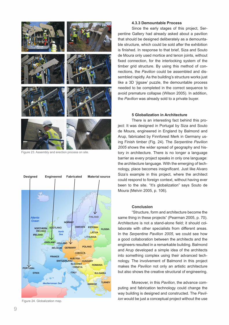
4.3.1 Delivery Process The fabricated LVL timbers were transported from Finnforest Merk factory to the site in London in just two lorry loads (Spring 2005). Finnforest Merk took the control of construction management in an assembly process. The installation of the timber beams spent around one month to completely finish, with only ten joiners working on site (Wilson 2005). By prefabricating all materials first, it increased the ef-ficiency during the construction stage as it only takes small group of on-site labors, it consumed less con-struction time and there was no need to bring heavy machine and big truck to the site. Moreover, since there were 427 different size of timbers, labeling was crucial during delivery process. It enabled on-site la-bors to easily determine the location of each timber, which directly relates to the erection sequence. So, before transported, Finnforest Merk already labeled each member with “the unique structural grid refer-ence for that member” (Self et al 2005, p. 21).
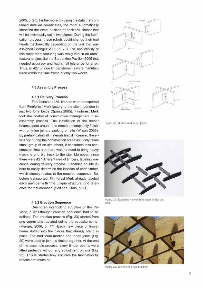
4.3.2 Erection Sequence Due to an interlocking structure of the Pa-vilion, a well-thought erection sequence had to be defined. The erection process (Fig. 23) started from one corner and radiated out to the opposite corner (Mengez 2006, p. 77). Each new piece of timber beam slotted into the pieces that already stand in place. The traditional mortice and tenon joints (Fig. 20) were used to join the timber together. At the end of the assemble process, every timber beams were fitted perfectly without any adjustment on site (Fig. 22). This illustrates how accurate the fabrication by robotic arm machine.
8
the Portuguese. Stones used for ballast for ships found theirway into churches in Brazil, replaced for the return voyage bygold. Ideas, circulated by travellers or magazines, havealways eluded specific localities. ‘It’s globalisation,’ saysSouto de Moura.
Given that Siza, Souto de Moura and Balmond collaborate asa trio and in each possible pairing, the relationship is a happyone. Siza enjoys working with engineers. At the Serpentine, hesays, engineering ‘helped to give scale’ to the design, as wellas expertise in timber performance. Such support frees him up
to do ‘what only the architect can do’. The mostimportant aspect, he continues, is ‘coordination’between the various parts: physical, environmental andprogrammatic. To avoid ‘chaos’, someone has to havethe overall vision, to ‘maintain the basic idea, but also tobe able to transform it’, to synthesise yet transcend theconstraints of the various influences. Far from chaotic,the Serpentine Gallery Pavilion is an erudite essay inthe subtle complexity of form that comes through suchtransformations of basic matter and impression. 4+
106 +
Top leftThe actual jointing technology is the traditional mortice and tenon. It is the formthat arises from the joints and profiles of the timber that is innovative.
Bottom leftPlan: the building is almost like a rug spread for a picnic in the park, takingshelter from the trees and succour from the existing gallery. +
Top, middle and bottom right Three different visions: sketches by Siza(interior view), Souto de Moura (interior view) and Balmond (inter aliaoverall structural form on the left, and ideas for connections on theright). Even their early sketches are revealing. Siza’s encapsulates almostevery feature of the completed building, and Souto de Moura’s capturesthe power of the space and, on the bottom right, the essential plan form,while picking up the formal and spatial ideas and representing them in a way that can translate into structure and construction.
Figure 21. Exploding view of how each timber ele-ment.
Figure 20. Mortice and tenon joints
Figure 22. Joints in the real building
4.3.3 Demountable Process Since the early stages of this project, Ser-pentine Gallery had already asked about a pavilion that should be designed deliberately as a demounta-ble structure, which could be sold after the exhibition is finished. In response to that brief, Siza and Souto de Moura only used mortice and tenon joints, without fixed connection, for the interlocking system of the timber grid structure. By using this method of con-nections, the Pavilion could be assembled and dis-sembled rapidly. As the building’s structure works just like a 3D ‘jigsaw’ puzzle, the demountable process needed to be completed in the correct sequence to avoid premature collapse (Wilson 2005). In addition, the Pavilion was already sold to a private buyer.
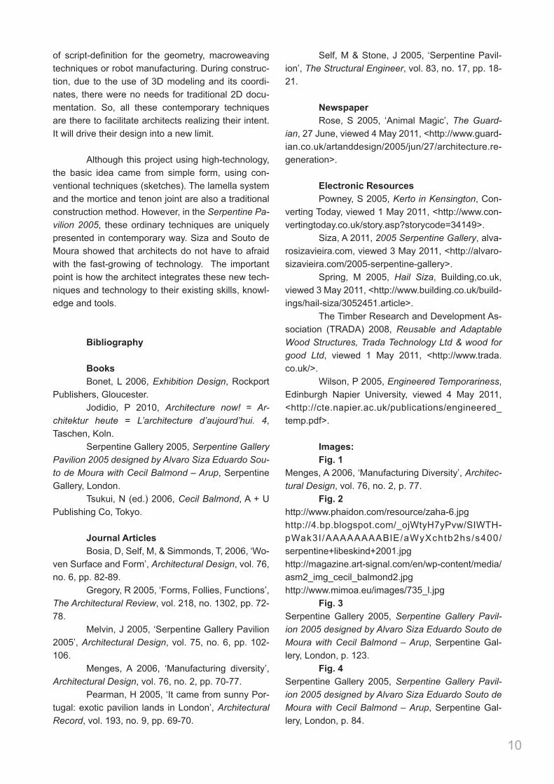
5 Globalization in Architecture There is an interesting fact behind this pro-ject: It was designed in Portugal by Siza and Souto de Moura, engineered in England by Balmond and Arup, fabricated by Finnforest Merk in Germany us-ing Finish timber (Fig. 24). The Serpentine Pavilion 2005 shows the wider spread of geography and his-tory in architecture. There is no longer a language barrier as every project speaks in only one language: the architecture language. With the emerging of tech-nology, place becomes insignificant. Just like Alvaro Siza’s example in this project, where the architect could respond to foreign context, without having ever been to the site. “It’s globalization” says Souto de Moura (Melvin 2005, p. 106).
Conclusion “Structure, form and architecture become the same thing in these projects” (Pearman 2005, p. 70). Architecture is not a stand-alone field; it should col-laborate with other specialists from different areas. In the Serpentine Pavilion 2005, we could see how a good collaboration between the architects and the engineers resulted in a remarkable building. Balmond and Arup developed a simple idea of the architects into something complex using their advanced tech-nology. The involvement of Balmond in this project makes the Pavilion not only an artistic architecture but also shows the creative structural of engineering.
Moreover, in this Pavilion, the advance com-puting and fabrication technology could change the way building is designed and constructed. The Pavil-ion would be just a conceptual project without the use
9
Figure 23. Assembly and erection process on site.
Designed
FINLAND
Engineered Fabricated Material source
Figure 24. Globalization map.
of script-definition for the geometry, macroweaving techniques or robot manufacturing. During construc-tion, due to the use of 3D modeling and its coordi-nates, there were no needs for traditional 2D docu-mentation. So, all these contemporary techniques are there to facilitate architects realizing their intent. It will drive their design into a new limit.
Although this project using high-technology, the basic idea came from simple form, using con-ventional techniques (sketches). The lamella system and the mortice and tenon joint are also a traditional construction method. However, in the Serpentine Pa-vilion 2005, these ordinary techniques are uniquely presented in contemporary way. Siza and Souto de Moura showed that architects do not have to afraid with the fast-growing of technology. The important point is how the architect integrates these new tech-niques and technology to their existing skills, knowl-edge and tools.
Bibliography
Books Bonet, L 2006, Exhibition Design, Rockport Publishers, Gloucester. Jodidio, P 2010, Architecture now! = Ar-chitektur heute = L’architecture d’aujourd’hui. 4, Taschen, Koln. Serpentine Gallery 2005, Serpentine Gallery Pavilion 2005 designed by Alvaro Siza Eduardo Sou-to de Moura with Cecil Balmond – Arup, Serpentine Gallery, London. Tsukui, N (ed.) 2006, Cecil Balmond, A + U Publishing Co, Tokyo.
Journal Articles Bosia, D, Self, M, & Simmonds, T, 2006, ‘Wo-ven Surface and Form’, Architectural Design, vol. 76, no. 6, pp. 82-89. Gregory, R 2005, ‘Forms, Follies, Functions’, The Architectural Review, vol. 218, no. 1302, pp. 72-78. Melvin, J 2005, ‘Serpentine Gallery Pavilion 2005’, Architectural Design, vol. 75, no. 6, pp. 102-106. Menges, A 2006, ‘Manufacturing diversity’, Architectural Design, vol. 76, no. 2, pp. 70-77. Pearman, H 2005, ‘It came from sunny Por-tugal: exotic pavilion lands in London’, Architectural Record, vol. 193, no. 9, pp. 69-70.
Self, M & Stone, J 2005, ‘Serpentine Pavil-ion’, The Structural Engineer, vol. 83, no. 17, pp. 18-21.
Newspaper Rose, S 2005, ‘Animal Magic’, The Guard-ian, 27 June, viewed 4 May 2011, <http://www.guard-ian.co.uk/artanddesign/2005/jun/27/architecture.re-generation>.
Electronic Resources Powney, S 2005, Kerto in Kensington, Con-verting Today, viewed 1 May 2011, <http://www.con-vertingtoday.co.uk/story.asp?storycode=34149>. Siza, A 2011, 2005 Serpentine Gallery, alva-rosizavieira.com, viewed 3 May 2011, <http://alvaro-sizavieira.com/2005-serpentine-gallery>. Spring, M 2005, Hail Siza, Building,co.uk, viewed 3 May 2011, <http://www.building.co.uk/build-ings/hail-siza/3052451.article>. The Timber Research and Development As-sociation (TRADA) 2008, Reusable and Adaptable Wood Structures, Trada Technology Ltd & wood for good Ltd, viewed 1 May 2011, <http://www.trada.co.uk/>. Wilson, P 2005, Engineered Temporariness, Edinburgh Napier University, viewed 4 May 2011, <http://cte.napier.ac.uk/publications/engineered_temp.pdf>.
Images: Fig. 1 Menges, A 2006, ‘Manufacturing Diversity’, Architec-tural Design, vol. 76, no. 2, p. 77. Fig. 2 http://www.phaidon.com/resource/zaha-6.jpghttp://4.bp.blogspot.com/_ojWtyH7yPvw/SIWTH-pWak3I/AAAAAAAABlE/aWyXchtb2hs/s400/serpentine+libeskind+2001.jpghttp://magazine.art-signal.com/en/wp-content/media/asm2_img_cecil_balmond2.jpghttp://www.mimoa.eu/images/735_l.jpg Fig. 3 Serpentine Gallery 2005, Serpentine Gallery Pavil-ion 2005 designed by Alvaro Siza Eduardo Souto de Moura with Cecil Balmond – Arup, Serpentine Gal-lery, London, p. 123. Fig. 4 Serpentine Gallery 2005, Serpentine Gallery Pavil-ion 2005 designed by Alvaro Siza Eduardo Souto de Moura with Cecil Balmond – Arup, Serpentine Gal-lery, London, p. 84.
10
Fig. 5 Gouw, HI. Fig. 6 Gouw, HI. Fig. 7 Self, M & Stone, J 2005, ‘Serpentine Pavilion’, The Structural Engineer, vol. 83, no. 17, p. 21. Fig. 8 Serpentine Gallery 2005, Serpentine Gallery Pavil-ion 2005 designed by Alvaro Siza Eduardo Souto de Moura with Cecil Balmond – Arup, Serpentine Gal-lery, London, p. 122. Fig. 9 Serpentine Gallery 2005, Serpentine Gallery Pavil-ion 2005 designed by Alvaro Siza Eduardo Souto de Moura with Cecil Balmond – Arup, Serpentine Gal-lery, London, p. 125. Fig. 10 Serpentine Gallery 2005, Serpentine Gallery Pavil-ion 2005 designed by Alvaro Siza Eduardo Souto de Moura with Cecil Balmond – Arup, Serpentine Gal-lery, London, p. 86. Fig. 11Serpentine Gallery 2005, Serpentine Gallery Pavil-ion 2005 designed by Alvaro Siza Eduardo Souto de Moura with Cecil Balmond – Arup, Serpentine Gal-lery, London, p. 115. Fig. 12 Serpentine Gallery 2005, Serpentine Gallery Pavil-ion 2005 designed by Alvaro Siza Eduardo Souto de Moura with Cecil Balmond – Arup, Serpentine Gal-lery, London, p. 103. Fig. 13 Serpentine Gallery 2005, Serpentine Gallery Pavil-ion 2005 designed by Alvaro Siza Eduardo Souto de Moura with Cecil Balmond – Arup, Serpentine Gal-lery, London, p. 91.Serpentine Gallery 2005, Serpentine Gallery Pavil-ion 2005 designed by Alvaro Siza Eduardo Souto de Moura with Cecil Balmond – Arup, Serpentine Gal-lery, London, p. 100.Tsukui, N (ed.) 2006, Cecil Balmond, A + U Publishing Co, Tokyo, p. 29.Self, M & Stone, J 2005, ‘Serpentine Pavilion’, The Structural Engineer, vol. 83, no. 17, p. 18. Fig. 14Serpentine Gallery 2005, Serpentine Gallery Pavil-ion 2005 designed by Alvaro Siza Eduardo Souto de Moura with Cecil Balmond – Arup, Serpentine Gal-lery, London, p. 103. Fig. 15Self, M & Stone, J 2005, ‘Serpentine Pavilion’, The
Structural Engineer, vol. 83, no. 17, p. 18. Fig. 16Melvin, J 2005, ‘Serpentine Gallery Pavilion 2005’, Architectural Design, vol. 75, no. 6, p. 105. Fig. 17Tsukui, N (ed.) 2006, Cecil Balmond, A + U Publish-ing Co, Tokyo, p. 29. Fig, 18Tsukui, N (ed.) 2006, Cecil Balmond, A + U Publish-ing Co, Tokyo, p. 29. Fig. 19Menges, A 2006, ‘Manufacturing Diversity’, Architec-tural Design, vol. 76, no. 2, p. 76. Fig. 20Self, M & Stone, J 2005, ‘Serpentine Pavilion’, The Structural Engineer, vol. 83, no. 17, p. 20. Fig. 21Tsukui, N (ed.) 2006, Cecil Balmond, A + U Publish-ing Co, Tokyo, p. 29. Fig. 22Serpentine Gallery 2005, Serpentine Gallery Pavil-ion 2005 designed by Alvaro Siza Eduardo Souto de Moura with Cecil Balmond – Arup, Serpentine Gal-lery, London, p. 116. Fig. 23Tsukui, N (ed.) 2006, Cecil Balmond, A + U Publish-ing Co, Tokyo, pp. 30-31. Fig. 24http://topuspost.com/wp-content/uploads/2011/05/map-of-europe.jpg
11