Embed Size (px)
Citation preview
1
Technical Article
10/2011
The Standard Mix does it:
Standardization is very much the trend in the development of
automotive electronics. The use of open architectures and configu-
rable components are intended to let developers focus more on the
innovative and differentiating aspects of the development process.
In addition, standardization is intended to be a central measure
that contributes towards reducing costs. In the past, automotive
ECU software architectures were not standardized. For the supplier,
this resulted in different, OEM-specific software architectures that
required different development processes, development tools and
data exchange formats. AUTOSAR (AUTomotive Open System ARchi-
tecture) has the stated goal of standardizing a common, open
automotive software architecture. The primary goals of the
AUTOSAR architecture are:
> Hardware abstraction
> Clearly specified interfaces
> Standardized behavior of the basic software
> Standardized data exchange formats between OEM and suppliers
> Definition of a harmonized methodology for developing software
> Support of model-based functional development
> Scalability over all ECU and vehicle classes
> Considers safety requirements per ISO 26262
Today, AUTOSAR is the reference architecture for ECU software.
The first production launches with complete AUTOSAR software will
occur in the near future. The number of development projects uti-
lizing AUTOSAR methodology is continually growing.
The AUTOSAR Consortium is currently working on versions 3.2
Diagnostics with AUTOSAR and ODX – Part 1: Diagnostics with AUTOSAR
AUTOSAR is the future-oriented reference architecture for ECU software. Clearly specified interfaces, standardized behavior and XML-based data formats are the key features of this standard. In AUTOSAR, diagnostics is handled in the modules DCM (communications) and DEM (fault memory). This article first addresses diagnostics in AUTOSAR and related data formats. Description data in ODX format (Open Diagnostic Data Exchange) represents an alternative to configuring the diagnostic software. Part 2 will address the topic of “ODX in the AUTOSAR development process”.

2
Technical Article
10/2011
and 4.x. Versions 2.x, 3.x and 4.0, which were released prior to
this, have already been used as a basis for implementing vehicle
projects. Today, most vehicle producers work to versions 3.x.
Functional orientation is increasingly gaining in significance in
electronic development. AUTOSAR standardizes the description of
individual component or vehicle functions and the description of
the overall system in what is known as the System Configuration
Description. The methodology for distributing vehicle functions to
ECUs is also standardized. As a result, developed functions can be
reused in other vehicle projects without changes.
The example in Figure 1 illustrates this: The Lighting vehicle
function from the Function Library is subdivided into three sub-
functions. In vehicle A, the subfunctions are distributed to two
network ECUs, while in vehicle B they are distributed unchanged to
three ECUs. The communication between the subfunctions is
defined in the System Configuration Description.
In AUTOSAR, there is an ECU Extract of the System Configura-
tion for each ECU that covers the system content relevant to the
ECU – and often also relevant to a supplier.
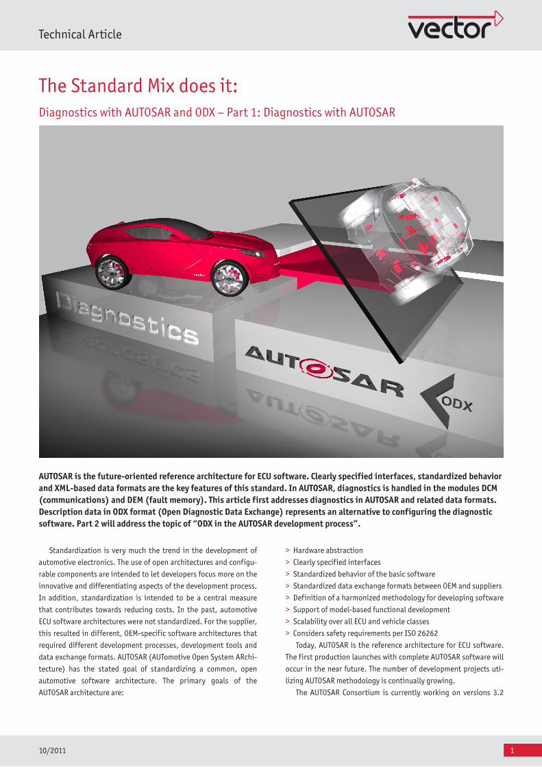
The elementary components of AUTOSAR architecture for ECU
software are:
> Functional software (SWC)
> Run-Time environment (RTE)
> Basic software (BSW)
The high level of reusability of the functional software is due to
the abstraction of communication by the Virtual Function Bus
(VFB). The application can be developed and tested without
knowledge of the underlying communication mechanisms. It does
not matter here whether communication occurs within the ECU or
over a network (CAN, FlexRay, etc.). The Run-Time-Environment
(RTE) serves as the runtime environment for the functional soft-
ware, and it implements the Virtual Function Bus for a specific ECU.
The basic software is developed as a component kit and is commer-
cially available (off-the-shelf software). It contains fundamental
system functions and abstracts the functional software from the
hardware. It is subdivided into three areas (Figure 2):
> The Service Layer provides basic services for the functional soft-
ware and other basic software modules.
> The ECU Abstraction Layer abstracts higher layers from the ECU
hardware
> The Microcontroller Abstraction Layer abstracts higher layers
from the specific microcontroller device
The ECU Configuration Description is used to configure the
basic software and the RTE. Initially, this configuration is generat-
ed from the ECU Extract of the System Configuration Description
(e.g. communication over the network). The ECU Configuration
Description plays a central role for the behavior of the entire ECU
software and is extended and adapted, step by step, over the
course of further development.
Diagnostics with AUTOSAR
The diagnostic software in AUTOSAR consists of three modules:
DCM, DEM and FIM. The DCM (Diagnostic Communication Manager)
implements the diagnostic communication per ISO 14229-1 (UDS)
Functional Library
Lighting
Seat Heating
Air Conditioning
Vehicle A
ECU Extractof System
Description
Vehicle B
HardwareTopology
DistributedSystem
SoftwareConfiguration
Figure 1: Functional distribution in AUTOSAR
3
Technical Article
10/2011
and SAE J1979 (OBDII). All diagnostic requests are first prepro-
cessed by the DCM. One of the tasks of the DCM is comprehensive
handling of invalid diagnostic requests. The DCM can already fully
process a majority of valid requests; it routes other requests to the
functional software. Each AUTOSAR release has increased the func-
tional range of the DCM, while continually decreasing the remain-
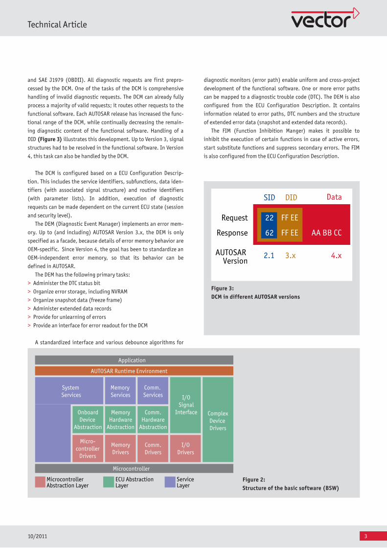
ing diagnostic content of the functional software. Handling of a
DID (Figure 3) illustrates this development. Up to Version 3, signal
structures had to be resolved in the functional software. In Version
4, this task can also be handled by the DCM.
The DCM is configured based on a ECU Configuration Descrip-
tion. This includes the service identifiers, subfunctions, data iden-
tifiers (with associated signal structure) and routine identifiers
(with parameter lists). In addition, execution of diagnostic
requests can be made dependent on the current ECU state (session
and security level).
The DEM (Diagnostic Event Manager) implements an error mem-
ory. Up to (and including) AUTOSAR Version 3.x, the DEM is only
specified as a facade, because details of error memory behavior are
OEM-specific. Since Version 4, the goal has been to standardize an
OEM-independent error memory, so that its behavior can be
defined in AUTOSAR.
The DEM has the following primary tasks:
> Administer the DTC status bit
> Organize error storage, including NVRAM
> Organize snapshot data (freeze frame)
> Administer extended data records
> Provide for unlearning of errors
> Provide an interface for error readout for the DCM
A standardized interface and various debounce algorithms for
Application
AUTOSAR Runtime Environment
ComplexDevice Drivers
I/OSignal
Interface
Comm. Services
Memory Services
Comm.Hardware
Abstraction
MemoryHardware
Abstraction
System Services
OnboardDevice
Abstraction
Micro-controller
Drivers
MemoryDrivers
Comm.Drivers
I/ODrivers
Microcontroller
MicrocontrollerAbstraction Layer
ECU Abstraction Layer
ServiceLayer
Fig ure 2:Structure of the basic software (BSW)
Fig ure 3:DCM in different AUTOSAR versions
Request 22 FF EE
Response 62 FF EE AA BB CC
SID DID Data
AUTOSAR Version
2.1 3.x 4.x
diagnostic monitors (error path) enable uniform and cross-project
development of the functional software. One or more error paths
can be mapped to a diagnostic trouble code (DTC). The DEM is also
configured from the ECU Configuration Description. It contains
information related to error paths, DTC numbers and the structure
of extended error data (snapshot and extended data records).
The FIM (Function Inhibition Manger) makes it possible to
inhibit the execution of certain functions in case of active errors,
start substitute functions and suppress secondary errors. The FIM
is also configured from the ECU Configuration Description.
4
Technical Article
10/2011
>> Your Contact:
Germany and all countries, not named belowVector Informatik GmbH, Stuttgart, Germany, www.vector.com
France, Belgium, Luxembourg Vector France, Paris, France, www.vector-france.com
Sweden, Denmark, Norway, Finland, IcelandVecScan AB, Göteborg, Sweden, www.vector-scandinavia.com
Great BritainVector GB Ltd., Birmingham, United Kingdom, www.vector-gb.co.uk
USA, Canada, MexicoVector CANtech, Inc., Detroit, USA, www.vector-cantech.com
JapanVector Japan Co., Ltd., Tokyo, Japan, www.vector-japan.co.jp
KoreaVector Korea IT Inc., Seoul, Republic of Korea, www.vector.kr
IndiaVector Informatik India Prv. Ltd., Pune, India, www.vector.in
ChinaVector Informatik GmbH Shanghai Representative Office,
Shanghai, China, www.vector-china.com
E-Mail [email protected]
Basic software modules for diagnostics with AUTOSAR
Vector’s MICROSAR product line provides an AUTOSAR solution
for ECU software consisting of the RTE and basic software modules
that cover the entire scope of the AUTOSAR standard. Each AUTO-
SAR BSW module is assigned to a MICROSAR package. The MICRO-
SAR DIAG package is specially available for diagnostics. It contains
the three BSW modules DCM, DEM and FIM from the AUTOSAR archi-
tecture. MICROSAR DIAG as the diagnostic software provides vehi-
cle projects with an AUTOSAR-compatible implementation of the
UDS protocol ISO 14229-1:2006.
Note: Part 2 “ODX in the AUTOSAR development process” is also
available for download at www.vector.com/downloads/.
Translation of a German publication in Hanser Automotive, 10/2011
Literature:[1] AUTOSAR specifications: www.autosar.org[2] Pascale Morizur, Matthias Wernicke, Justus Maier: Neue Wege zur Steuergeräte-Software Teil 1, Elektronik automotive 11.2009[3] Pascale Morizur, Matthias Wernicke, Justus Maier: Neue Wege zur Steuergeräte-Software Teil 2, Elektronik automotive 12.2009[4] ISO 14229: Road vehicles - Unified diagnostic services (UDS)[5] ISO 26262: Road vehicles - Functional safety[6] ISO 22901: Road vehicles - Open diagnostic data exchange (ODX)[7] Klaus Beiter, Oliver Garnatz, Christoph Rätz: Gesetzliche On-Board-Diagnose und ODX, Diagnose in mechatronischen Fahrzeugsystemen III S. 44 ff., Expert-Verlag 2010
Dr. Klaus Beiter leads a development team for the Automotive Diagnostics product line at the company Vector Informatik GmbH in Stuttgart. He is a member of the ASAM/ISO ODX working group.
Oliver Garnatz (Dipl Ing. (FH)) is employed at Vector Informatik GmbH as a product man-ager in the Embedded Software Components area. He is a member of the Automotive Diag-nostics area of ISO and the AUTOSAR area.
Christoph Rätz (Dipl-Ing. (BA)) graduated in Computer Science at the Cooperative State University of Stuttgart. He is the Global Prod-uct Line Manager of the Diagnostics product line at the company Vector Informatik GmbH in Stuttgart.


![Offloaded Data Transfer [ODX] for SPC4/SBC3 storage...2016 Storage Developer Conference - India. © EMC Corporation. All Rights Reserved. ODX Capable Storage ODX uses three new SCSI](https://img.pdfslide.net/doc/110x75/5edc632bad6a402d666706f4/offloaded-data-transfer-odx-for-spc4sbc3-storage-2016-storage-developer-conference.jpg)