Embed Size (px)
Citation preview
INTERIM NATIONAL REPORT ON
THE STRESS TESTS FOR NUCLEAR POWER PLANTS IN
SLOVAKIA
NUCLEAR REGULATORY AUTHORITY
OF THE SLOVAK REPUBLIC
15 SEPTEMBER 2011
CONTENT
1. Introduction ........................................................................................................... 3
2. General information about nuclear power plants .................................................. 3
3. Lessons learned from Fukushima accident .......................................................... 8
4. Specification and scope of stress tests ................................................................. 9
5. Methodology of stress tests ................................................................................ 10
6. Structure of the final report to be developed....................................................... 10
7. Status of works and preliminary results .............................................................. 11
Appendix I The Fukushima Daiichi NPP accident and lessons learned ............................................ 14
I.1. Chronology of the events ................................................................................................................. 14
I.2. Initiating events and plant weaknesses ........................................................................................... 17
I.3. Roadmap for safety restoration ....................................................................................................... 20
I.4. Lessons learnt and potential consequences on existing plants ...................................................... 22
I.5. Detailed analysis of failures ............................................................................................................. 22
I.6. Potential upgrading measures on existing plants ............................................................................ 27
Appendix II Methodology of stress tests ............................................................................................ 32
II.1. Deterministic assessment of fulfilment of safety functions – configuration matrix approach .......... 32
II.2. Development of the database .......................................................................................................... 33
II.3. Application of the database for assessment .................................................................................... 35
Appendix III Methodology of stress tests for MO 34 .......................................................................... 37
III.1. General description of methodology ................................................................................................ 37
III.2. Application of methodology to earthquakes..................................................................................... 39
III.3. Application of methodology to flooding ............................................................................................ 40
III.4. Application of methodology to extreme natural conditions .............................................................. 40
1. Introduction In view of the lessons learned from 11 March 2011 Fukushima accident the owner and operator of nuclear power plants (NPPs) in Slovakia – joint stock company Slovenske elektrarne a.s. (SE a.s.) has committed himself to perform so called stress tests on all units in operation or under construction. The task was further specified and its scope outlined in the letter of the Slovak Nuclear Regulatory Authority (UJD SR) of 15 June 2011 and during several subsequent meetings between the operator and the regulatory body.
This is an interim national report describing the approach used and current status of the works within the stress tests for nuclear power plants in Slovakia. The report has been prepared by the UJD SR in close cooperation with SE a.s. based on background reports prepared by SE a.s.
The final reports for all nuclear units in Slovakia will be developed by the licensee in accordance with the established schedule on 31 October 2011 and subsequently the national report will be prepared by the regulatory body by the end of 2011.
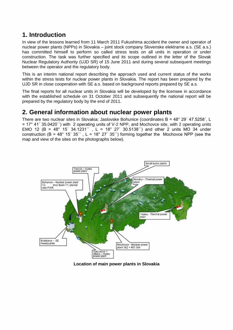
2. General information about nuclear power plants There are two nuclear sites in Slovakia: Jaslovske Bohunice (coordinates B = 48° 29´ 47.5258´, L = 17° 41´ 35.0420´´) with 2 operating units of V-2 NPP, and Mochovce site, with 2 operating units EMO 12 (B = 48° 15´ 34.1231´´ , L = 18° 27´ 30.5138´´) and other 2 units MO 34 under construction (B = 48° 15´ 35´´ , L = 18° 27´ 35´´) forming together the Mochovce NPP (see the map and view of the sites on the photographs below).
Location of main power plants in Slovakia
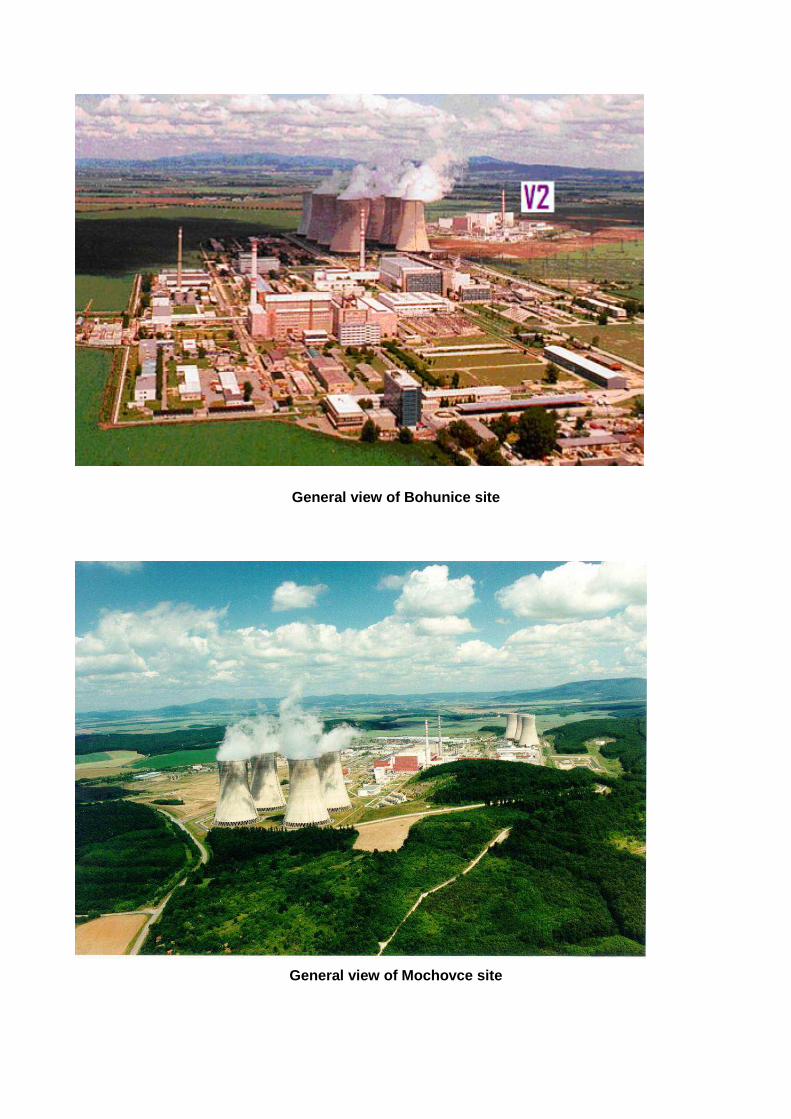
General view of Bohunice site
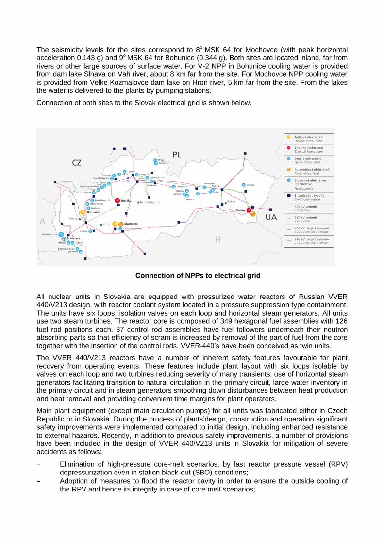
General view of Mochovce site
The seismicity levels for the sites correspond to 8o MSK 64 for Mochovce (with peak horizontal acceleration 0.143 g) and 9o MSK 64 for Bohunice (0.344 g). Both sites are located inland, far from rivers or other large sources of surface water. For V-2 NPP in Bohunice cooling water is provided from dam lake Slnava on Vah river, about 8 km far from the site. For Mochovce NPP cooling water is provided from Velke Kozmalovce dam lake on Hron river, 5 km far from the site. From the lakes the water is delivered to the plants by pumping stations.
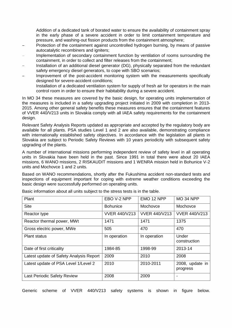
Connection of both sites to the Slovak electrical grid is shown below.
Connection of NPPs to electrical grid
All nuclear units in Slovakia are equipped with pressurized water reactors of Russian VVER 440/V213 design, with reactor coolant system located in a pressure suppression type containment. The units have six loops, isolation valves on each loop and horizontal steam generators. All units use two steam turbines. The reactor core is composed of 349 hexagonal fuel assemblies with 126 fuel rod positions each. 37 control rod assemblies have fuel followers underneath their neutron absorbing parts so that efficiency of scram is increased by removal of the part of fuel from the core together with the insertion of the control rods. VVER-440’s have been conceived as twin units.
The VVER 440/V213 reactors have a number of inherent safety features favourable for plant recovery from operating events. These features include plant layout with six loops isolable by valves on each loop and two turbines reducing severity of many transients, use of horizontal steam generators facilitating transition to natural circulation in the primary circuit, large water inventory in the primary circuit and in steam generators smoothing down disturbances between heat production and heat removal and providing convenient time margins for plant operators.
Main plant equipment (except main circulation pumps) for all units was fabricated either in Czech Republic or in Slovakia. During the process of plants’design, construction and operation significant safety improvements were implemented compared to initial design, including enhanced resistance to external hazards. Recently, in addition to previous safety improvements, a number of provisions have been included in the design of VVER 440/V213 units in Slovakia for mitigation of severe accidents as follows:
Elimination of high-pressure core-melt scenarios, by fast reactor pressure vessel (RPV) depressurization even in station black-out (SBO) conditions;
Adoption of measures to flood the reactor cavity in order to ensure the outside cooling of the RPV and hence its integrity in case of core melt scenarios;
Addition of a dedicated tank of borated water to ensure the availability of containment spray in the early phase of a severe accident in order to limit containment temperature and pressure, and washing-out fission products from the containment atmosphere;
Protection of the containment against uncontrolled hydrogen burning, by means of passive autocatalytic recombiners and igniters;
Implementation of secondary containment function by ventilation of rooms surrounding the containment, in order to collect and filter releases from the containment;
Installation of an additional diesel generator (DG), physically separated from the redundant safety emergency diesel generators, to cope with SBO scenarios;
Improvement of the post-accident monitoring system with the measurements specifically designed for severe-accident conditions;
Installation of a dedicated ventilation system for supply of fresh air for operators in the main control room in order to ensure their habitability during a severe accident.
In MO 34 these measures are covered by the basic design, for operating units implementation of the measures is included in a safety upgrading project initiated in 2009 with completion in 2013-2015. Among other general safety benefits these measures ensures that the containment features of VVER 440/V213 units in Slovakia comply with all IAEA safety requirements for the containment design.
Relevant Safety Analysis Reports updated as appropriate and accepted by the regulatory body are available for all plants. PSA studies Level 1 and 2 are also available, demonstrating compliance with internationally established safety objectives. In accordance with the legislation all plants in Slovakia are subject to Periodic Safety Reviews with 10 years periodicity with subsequent safety upgrading of the plants.
A number of international missions performing independent review of safety level in all operating units in Slovakia have been held in the past. Since 1991 in total there were about 20 IAEA missions, 6 WANO missions, 2 RISKAUDIT missions and 1 WENRA mission held in Bohunice V-2 units and Mochovce 1 and 2 units.
Based on WANO recommendations, shortly after the Fukushima accident non-standard tests and inspections of equipment important for coping with extreme weather conditions exceeding the basic design were successfully performed on operating units.
Basic information about all units subject to the stress tests is in the table.
Plant EBO V-2 NPP EMO 12 NPP MO 34 NPP
Site Bohunice Mochovce Mochovce
Reactor type VVER 440/V213 VVER 440/V213 VVER 440/V213
Reactor thermal power, MWt 1471 1471 1375
Gross electric power, MWe 505 470 470
Plant status In operation In operation Under construction
Date of first criticality 1984-85 1998-99 2013-14
Latest update of Safety Analysis Report 2009 2010 2008
Latest update of PSA Level 1/Level 2 2010 2010-2011 2008, update in progress
Last Periodic Safety Review 2008 2009 -
Generic scheme of VVER 440/V213 safety systems is shown in figure below.
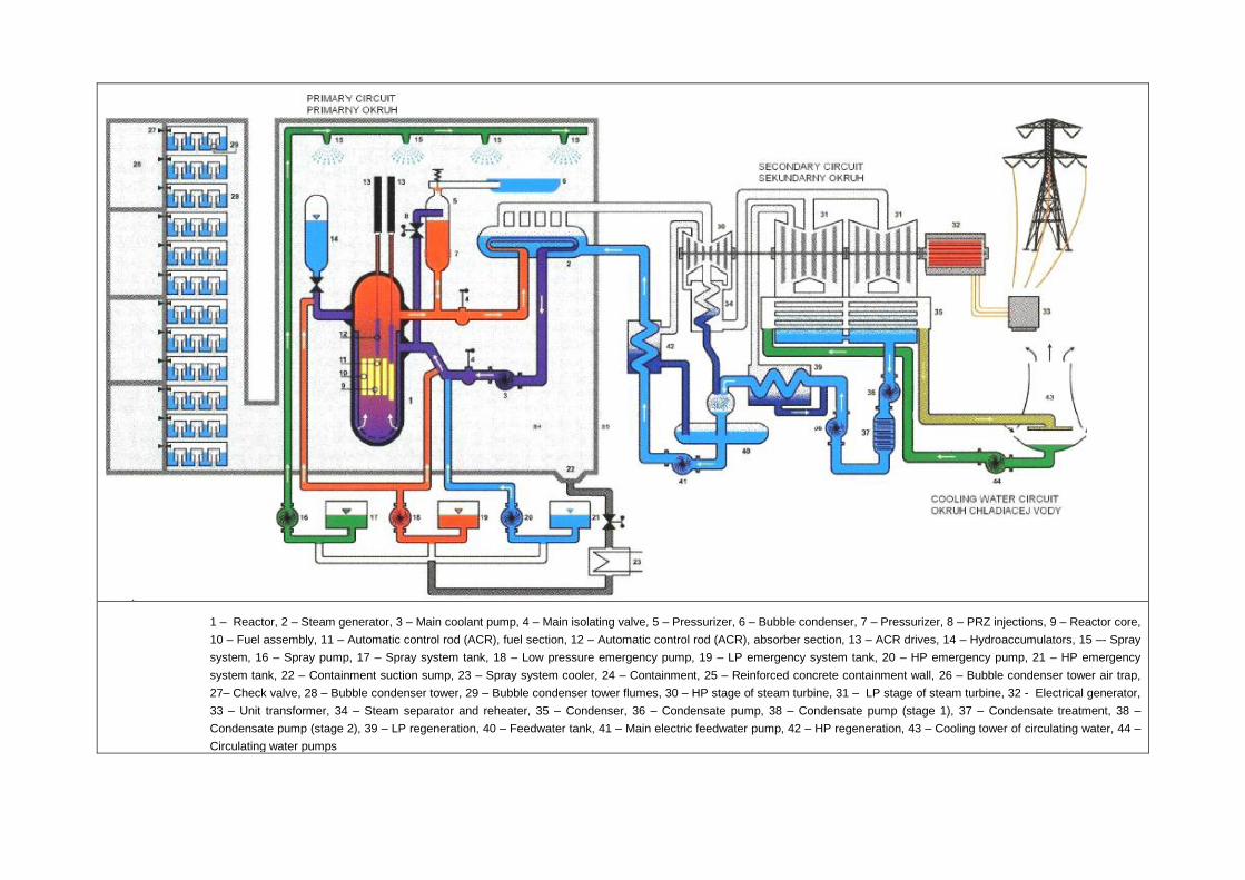
1 – Reactor, 2 – Steam generator, 3 – Main coolant pump, 4 – Main isolating valve, 5 – Pressurizer, 6 – Bubble condenser, 7 – Pressurizer, 8 – PRZ injections, 9 – Reactor core,
10 – Fuel assembly, 11 – Automatic control rod (ACR), fuel section, 12 – Automatic control rod (ACR), absorber section, 13 – ACR drives, 14 – Hydroaccumulators, 15 –- Spray
system, 16 – Spray pump, 17 – Spray system tank, 18 – Low pressure emergency pump, 19 – LP emergency system tank, 20 – HP emergency pump, 21 – HP emergency
system tank, 22 – Containment suction sump, 23 – Spray system cooler, 24 – Containment, 25 – Reinforced concrete containment wall, 26 – Bubble condenser tower air trap,
27– Check valve, 28 – Bubble condenser tower, 29 – Bubble condenser tower flumes, 30 – HP stage of steam turbine, 31 – LP stage of steam turbine, 32 - Electrical generator,
33 – Unit transformer, 34 – Steam separator and reheater, 35 – Condenser, 36 – Condensate pump, 38 – Condensate pump (stage 1), 37 – Condensate treatment, 38 –
Condensate pump (stage 2), 39 – LP regeneration, 40 – Feedwater tank, 41 – Main electric feedwater pump, 42 – HP regeneration, 43 – Cooling tower of circulating water, 44 –
Circulating water pumps
3. Lessons learned from Fukushima accident
Prior to the stress tests the Fukushima accident has been studied in detail. Summary of this study is presented in Appendix I. Appendix I has two main parts: one part provides background information about the Fukushima Daiichi NPP and covers the main aspects of the accident: the initiator seismic event and consequent tsunami, the evolution of the accident, the current situation and the roadmap for the safety restoration. The second part describes the main lessons learnt from the accident and indicates possible ways for further enhancing safety margins for existing plants. Of course, more detailed analysis needed for specification of future improvements for nuclear units in Slovakia is being performed within the stress tests and the results will be presented in the final report.
It came out from the study that there are both similarities and differences in the site conditions of Fukushima and sites in Slovakia, as well as in the designs of Fukushima units and VVER 440/V213 units. These items should be taken into account when utilizing lessons learned from the Fukushima accident. Specifically the information about Fukushima Unit 1 with reactor thermal power (1380 MWt) similar to VVER 440 was taken as a basis for the comparison. Some of the observations are summarized below:
Fukushima as well as Slovak sites have increased level of seismicity. However, seismicity level of Fukushima site is significantly higher, corresponding to 10o MSK 64 (with maximum horizontal acceleration ~0.5 g), while for Bohunice it is 9o MSK 64 (with 0.344 g) and for Mochovce it is 8o MSK 64 (with 0.143 g). Nevertheless the seismicity is the relevant issue for Slovak sites which need to be addressed more in detail.
Combination of an earthquake and flooding due to tsunami (main damaging factor in Fukushima) is irrelevant for sites in Slovakia and can be practically eliminated from further considerations. The only meaningful source of external flooding is extreme precipitation. However, differently from tsunami the flooding due to precipitation does not occur suddenly and it is not associated with damaging hydrodynamic wave, therefore time margins exist and damaging impact is much less significant. Nevertheless the flooding and extreme meteorological conditions are considered within the stress tests.
In case of station black-out the heat removal from the primary circuit can be ensured in the Fukushima 1 design by natural circulation of steam and water through 2 isolation condensers (normally separated from the reactor by isolation valves) containing altogether 212 t of water available for evaporation. In case of VVER 440/V213 residual heat is removed by natural circulation through permanently connected 6 steam generators containing about 330 t of water.
Both designs have significant amount of zirconium alloys in the reactor core due to use of zirconium not only in fuel cladding, but also in fuel channel shroud tubes. Amount of zirconium and hydrogen produced could be comparable, but receiving containment volume is much larger in case of VVER 440/V213. Nevertheless the hydrogen is the issue to be addressed for both designs.
Both designs have quite large volume of water beneath of the reactor core (compared to other PWR designs), which facilitates potential quenching of core debris in the lower plenum, in particular in case of early recovery of reactor coolant system injection in case of a beyond design basis accident. Reactor vessel design of VVER 440 is however less vulnerable to vessel penetration by molten corium due to the fact that that differently from BWR there are no instrumentation and control rod nozzles in the reactor vessel bottom.
Layout of the reactor coolant system and amount of coolant in the system lead in case of station black-out for Fukushima design to early and complete core uncovery, while for
VVER 440/V213 even with over-conservatively neglecting any operator actions the time margin to core uncovery is notably longer.
Both designs have a containment of the pressure suppression type, using water for condensing of steam. However, containment capacity is quite different. In case of Fukushima the containment free volume is about 6000 m3, and volume of water in condensation chamber 1750 m3. VVER 440/V213 has much larger containment free volume ~52000 m3, therefore less vulnerable for hydrogen explosions and to overpressurization, with volume of water in shelf condensation trays ~1300 m3, which are less vulnerable to pressure waves
Implementation of severe accident mitigation features were at the stage of consideration in Fukushima since 2010. Such features are fully covered by the design of MO 34 under construction, and their implementation is ongoing since in all operation units, with completion in V-2 and EMO 12 in 2013 and 2015, respectively.
4. Specification and scope of stress tests Stress test is a targeted assessment of the safety margins associated with extreme natural events challenging safety functions and leading to a severe accident. The assessment is deterministic in its nature and is aimed at verification of implementation of defence in depth in NPPs. The objective of the stress tests is to determine which level of severity of an external hazard the NPP can withstand without severe damage of the nuclear fuel (in the reactor core or in the spent fuel) or without significant releases of radioactive materials into the environment. Previous studies did not have this as an objective, since normally the plant structures, systems and components were designed to cope with the loads caused by external hazards within the plant design basis covering all events with non-negligible frequency of occurrence. It also means that in the stress tests the NPPs are assessed regarding the margins they have to cope in connection with the extremely unlikely hazards originally not considered in their design.
In accordance with ENSREG specification the assessment is focused on extreme natural events potentially causing extended loss of power supply and/or loss of ultimate heat sink, possibly occurring on several units at the same time.
The stress tests are aimed to assess existing capabilities of nuclear power plants and their staff to cope with extreme external hazards, in particular earthquakes, flooding, and extreme meteorological conditions, which can eventually result in loss of fundamental safety functions for both fuel in the reactor as well as in the spent fuel pool: reactor shutdown and its maintaining in subcritical conditions, residual heat removal and maintaining radioactive materials within the physical barriers. The assessment is complemented by an estimate of limiting parameters and time margins to irrecoverable degradation processes (cliff-edge effects).
The assessment has 3 components:
Assessment of the adequacy of selection of extreme natural events, capability of the plants to cope with such events and determination of the range of events (determination of margins) potentially leading to severe conditions. Extreme natural events relevant for nuclear sites in Slovakia and covered by this report include:
o Earthquakes,
o Flooding from various sources of water (surface water, underground water, bad weather conditions),
o Other extreme meteorological conditions (extreme temperatures, humidity, drought, ice, snow, wind),
o Combination of extreme natural events.
Assessment of consequences and measures for prevention of loss of safety functions from any initiating event conceivable at the plant site in case of loss of electric power, including station black out (SBO), loss of ultimate heat sink, or combination of both.
Assessment of severe accident management issues (design and operational provisions available to eliminate challenges to containment integrity after severe fuel damage).
One of the principal objectives of the assessment is to indicate possibilities for the increase robustness of the plant under conditions of extreme natural events.
For performing the stress tests a project team was established in SE a.s. The activities were governed and coordinated by the steering committee composed of top managers of SE a.s. For individual plants the tests were performed in coordinated way by 3 different groups of plant engineering staff, involving in total about 30 people. Information for the stress tests was collected from existing design and safety documentation, other supporting documentation mainly in the area of safety analysis, additional special analyses, inspections, non-standard tests, engineering judgment and to large extent also plant walk-down.
The stress tests are continuously reviewed by UJD SR that is focusing mainly on the scope, methodology and preliminary results. The final report will reflect all comments and requirements imposed by the national regulator. Preliminary results are summarized in chapter 7.
5. Methodology of stress tests
For determination of safety margins a systematic approach called Configuration Matrix Approach was developed and used based on verification of performance of the fundamental safety functions (both related to fuel in the reactor as well as in the spent fuel pools). The approach identifies all feasible configurations of plant systems capable of maintaining safety functions, verifies presence of all conditions for functioning of these systems (power supply, working medium, instrumentation, environmental conditions, accessibility by operators, availability of procedures) and assesses how eventually these systems can be disabled in their turn with increasing load induced due to external hazards. All relevant information was arranged in a database which will be also used for future plant safety assessments. As basic results of the assessments various configurations of plant systems and available time margins for recovery are identified depending on severity of the external hazard. Finally the feasible measures for further enhancement of safety margins beyond the plant design basis are identified. The Configuration Matrix Approach is described in more detail in Appendix II.
In MO 34 units under construction the method of stress tests was partially modified since due to status of the plant construction it was difficult to collect all data necessary for filling in the database. The modified method is briefly described in Appendix III.
Although it is clear that from safety point of view it is more convenient to have more lines of defence available (more configurations) and larger time margins for plant recovery, no fixed acceptance criteria can be applied to the stress test because of the fact that there are no reference values specified for situations categorized as extremely unlikely and beyond the existing national and international safety standards.
6. Structure of the final report to be developed In order to facilitate future peer review and to ensure comprehensiveness of the documentation it was agreed to follow as closely as possible the structure of the report specified by ENSREG in the letter dated 17 July 2011. The report will consist of the following main parts:
Chapter 1 will contain general information about the plant, focusing on description of all relevant systems providing or supporting the main safety functions and on possibilities to use them under conditions of extreme natural event. Scope and main results of the probabilistic safety assessment will be also briefly summarized.
Chapters 2 to 4 will be devoted to description of extreme natural hazards specific for nuclear sites in Slovakia. Earthquakes, flooding (including their combination) and extreme meteorological conditions will be covered. The description will include characterization of events against which the plants are designed, provisions to protect the plants against such events, and assessment of the range of external events which could lead either to fuel damage or to loss of containment integrity. Potentials to increase robustness of the plant will be identified. Chapter 2 will cover the earthquakes, chapter 3 flooding, and chapter 4 extreme weather conditions.
Chapter 5 will deal with special events potentially resulting from the extreme natural events, in particular with loss of electric power and loss of ultimate heat sink, and combination of them. The chapter will focus on overview of consecutive measures available for prevention of severe fuel damage in the core or in the spent fuel pool, including description of all means and evaluation of time margins for recovery of situation in various circumstances.
Chapter 6 will deal both with organizational as well as technical aspects of severe accident management, concentrating on description of mitigative actions to be taken after severe fuel damage to prevent large radioactive releases by maintaining containment integrity. Possibilities to use existing equipment and measures feasible to enhance such possibilities will be identified. The design and operational provisions available to eliminate various challenges to containment integrity will be described.
There will be a number of appendices to this report. In addition to appendices already included to this interim report they will cover an overview of areas for improvements and the plan for implementation of the improvements.
7. Status of works and preliminary results
The works on stress tests are in progress, focusing at present on completion of data bases necessary for comprehensive assessment of configurations needed for maintaining safety functions, vulnerability of these systems to external hazards, and identification of feasible measures for further enhancement of plant safety margins. The works are organized so that the assessment will be finished by the SE a.s. by end of October 2011, with subsequent development of the full national report by end of the year 2011. Preliminary results of the works are briefly summarized below.
Stress tests were found to be a useful exercise offering to assess more deeply the safety level of nuclear power plants in Slovakia for potential hazards caused by extreme natural events. The results confirmed that external events were selected in the design basis in accordance with the state of the art methods and that the plant designs are capable to cope with these events. In addition there are certain safety margins available which allow management of beyond design basis accident without core damage and without loss of containment integrity. Plant design is robust in compliance with principles of defence in depth, including level 4 of defence devoted to prevention and management of severe accidents. On units MO 34 under construction the severe accident mitigation measures are part of the design, for operating units the same measures are included in the ongoing safety upgrading project executed since 2009, with the completion scheduled in 2013 (EBO V2) and 2015 (EMO 12). Nevertheless, in the stress tests additional safety upgrading measures are being identified, which allow enhancing further the existing margins beyond the design basis. None of the measures correspond to an imminent risk requiring prompt actions.
Earthquakes are relevant safety issues for both sites in Slovakia, in Mochovce corresponding to 8 o
MSK 64 with the maximum horizontal acceleration 0.143 g, in Bohunice corresponding to 9 o MSK 64 with 0.344 g, for return period once in 10000 years. Earthquakes have been considered in the plant design in accordance with relevant national and international requirements. Seismic margin assessment is ongoing and will be summarized in the final national report.
Regarding flooding the only meaningful cause for both sites is extreme precipitation. Site topography does not allow accumulation of water at any elevation where safety related buildings are located. No major additional measures to protect the plant against external flooding seem to be necessary. Nevertheless, possibilities of limited measures against external flooding (penetrations sealing and waterproofing of building basement) are being further investigated. In Mochovce, improvements of the original design in relation to external flooding have been already included in the basic design. It is expected that similar measures will be adopted at Bohunice V2 as well.
Other extreme natural conditions considered among extreme meteorological conditions are extreme temperatures (both low and high), humidity, drought, ice and wind. From the viewpoint of extreme temperatures, low temperatures represent higher risks. The extreme drought is not a phenomenon occurring suddenly and therefore allows for adequate preparation in advance. Regarding the impact of ice and snow the highest threat affecting the continuous water supply is clogging of siphon pipes in the water inlet from the water reservoirs. These events are however bounded by a total loss of make-up water considered separately in the assessment. The resistance of plant structures to extreme winds is capable to withstand wind loads more that 2-times higher than the design basis wind. In general the analysis showed that the safety systems are sufficiently protected against extreme meteorological conditions.
Regarding the risk of loss of power supply it may be taken into account that in both sites there are 8 different options for providing power supply to plant home consumers (not counting redundancies of each of them); 5 of these options are independent on the electricity distribution grid. These options can be initiated from few tens of seconds to one hour. Even if all these options would fail, inherent safety features of the design provide for sufficiently long heat removal and convenient time margins for recovery actions, both for events occurring during operation at power and even larger during shutdown regimes. Eventually, use of mobile water source feeding of SGs ensures that the core damage is avoided. For NPPs in Slovakia the external atmosphere serves as the ultimate heat sink. Although this UHS in principle can not be lost, the transport of heat to the UHS can be disabled. Such situations were subject of assessment within the stress tests. If normal plant cooling through the secondary circuit and cooling towers is not available, remaining options include direct release of steam from steam generators to atmosphere through the steam by-pass stations, or by primary circuit feed and bleed, or by heat removal through the essential service water system, the last one being applicable both under normal as well as under emergency conditions. Since failure of all essential service water systems could have serious consequences regarding heat removal from the core, from the spent fuel pool and from the containment, this case was analyzed in detail in the stress tests as the most sensitive one. If the loss of essential service water is not caused by the station black-out discussed above, loss of raw water supply should be considered. However, large water inventory of cooling water in each unit and on-site is adequate for sufficiently long heat removal.
The case of a combined station black-out and loss of ultimate heat sink in case of VVER 440/V213 design is in fact covered by the station black-out only, since the station black-out is always connected with the loss of ultimate heat sink.
The beyond-design basis accident (including severe accident) management project is a long-term controlled process running in stages since 1995. Symptom-based emergency operating procedures (EOPs) addressing design basis accidents and preventive part of severe accidents were fully implemented in EBO V2 and EMO 12 in 1999 (for events initiated during power operation) and in 2006 (for events initiated in the reactor under shutdown or in the spent fuel pool). Plant specific severe accident management guidelines (SAMG) were prepared for EBO V2 and

EMO 12 from 2002 to 2004 in cooperation with Westinghouse. In 2004-2005, an overall study defining technical specification of modifications and extensions of the WWER 213 basic design needed for implementation of SAMG prepared for the modified unit condition was prepared. The project of implementation of modifications to support the severe accident management on the basis of SAMG was proposed in compliance with all the requirements and recommendations in Slovak legislation in 2006 - 2007. The SAM implementation project was initiated in 2009 as the common EBO V2 and EMO 12 project with deadline in 2013 in EBO V2 and the follow-up implementation in EMO 12. Large part of the required plant modifications has been already implemented (e.g. installation of recombiners, measures for flooding of the reactor cavity). Until full implementation, the long-term heat removal from the containment after severe accident would be ensured by recovery of serviceability of the design basis equipment.
At the end of this report it should be underlined that the extensive work has to be performed in very limited time, in several cases not corresponding to the complexity of the task. It is therefore understood that in order to utilize fully the lessons learned from Fukushima more detailed studies will continue also in the future.
Appendix I The Fukushima Daiichi NPP accident and lessons learned This appendix has been prepared using a dedicated report developed by the operator with the aim of providing background information for the stress tests. The appendix has two main parts. The first part provides background information about the Fukushima Daiichi NPP and covers the main aspects of the accident: the initiator seismic event and consequent tsunami, the evolution of the accident, the current situation and the roadmap for the safety restoration. The second part describes the main lessons learnt from the accident and indicates possible ways for further enhancing safety margins for existing plants.
I.1. Chronology of the events
The Tohoku earthquake with magnitude 9.0 hit the East coast of Japan at 14:46 on Friday 11th March and the generated tsunami hit the coast soon after in a time delay of about 20 minutes. Eleven reactors at four nuclear power plants in the region were operating at the time: Fukushima Daiichi 1, 2, 3, Fukushima Daini 1, 2, 3, 4, Onagawa 1, 2, 3, and Tokai Daini 1 for a total amount of 9,377 MWe. All, as required, shut down automatically when the quake hit.
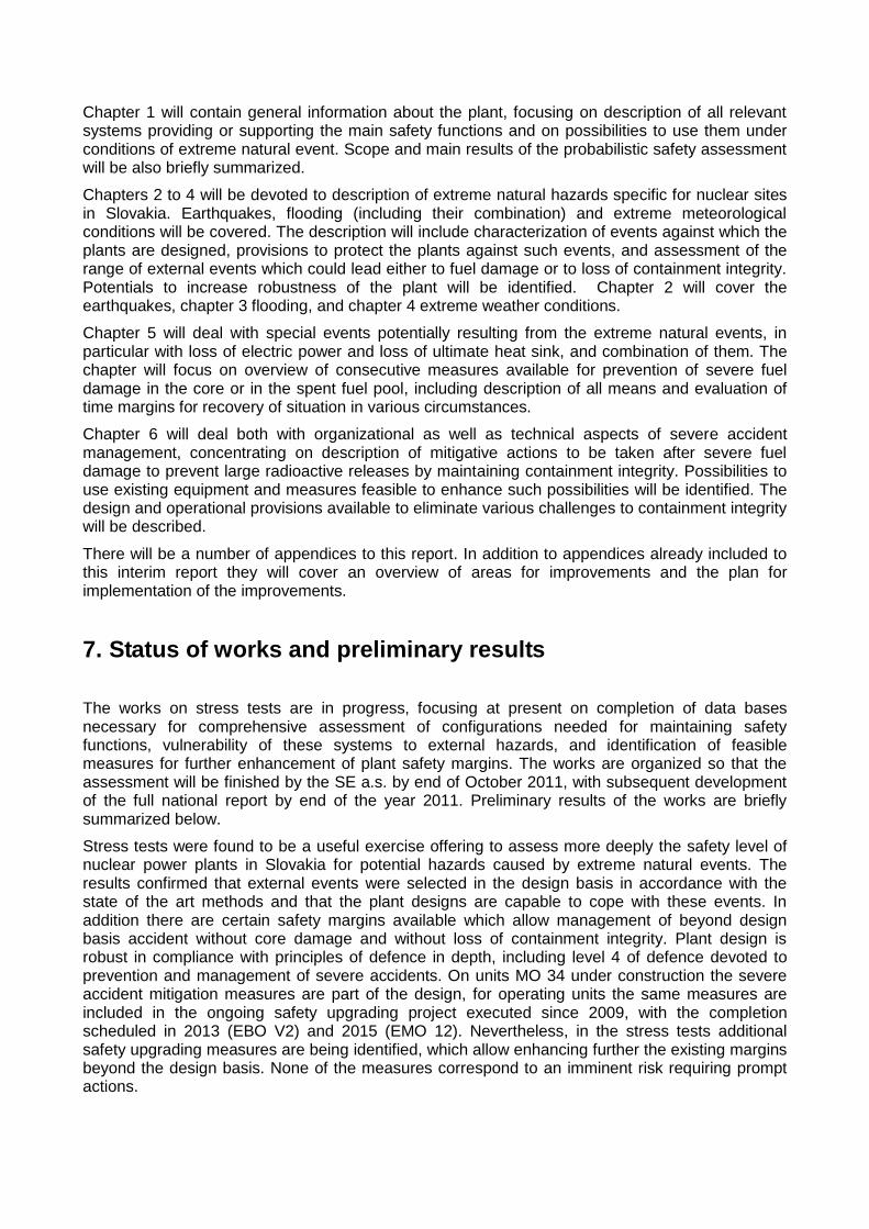
After the earthquake, control rods were automatically activated to stop nuclear reactions at units 1, 2 and 3. The remaining reactors, Units 4, 5 and 6, had previously been shut down for routine maintenance purposes. All 6 units in Fukushima Daiichi NPP are boiling water reactor (BWRs) designed more than 40 years ago; Unit 1 has a BWR3 reactor and MARK-1 containment, Units 2,3,4 are BWR4 MARK-1, Unit 5 is a BWR5 MARK-1 and Unit 6 is a BWR5 MARK-2. . After the earthquake all units were powered from backup emergency Diesel Generators (DG), started automatically after the loss of offsite power due to the seismic event.
Figure I.1 BWR plant design
The DGs, replacing the lost offsite power, ensured the cooling functions for the reactors, for the spent fuel pools of each reactor and for the site central spent fuel pool.
About one hour after the quake (15:41) the onsite electrical emergency power was lost due to the tsunami (14 m wave high) that destroyed the sea water intakes and overwhelmed the plants’ physical structures, causing inundation, wetting of many components and making many areas inaccessible. The resulting accident event was a “total station blackout” for units 1, 2, 3 and 4 together with the loss of the ultimate heat sink. In fact 12 out of 13 back-up DGs on site, located in the basements of the turbine buildings, were disabled (due to the flooding). Only one air-cooled DG was able to supply electric power to units 5 and 6, which remained under full control after some initial troubles. The batteries ensured the supply of some essential loads for a certain time; after a few hours the DC-power was also lost and the control rooms remained practically unavailable and in the darkness.
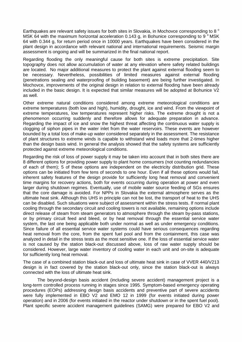
Following the station blackout some cooling of the core in the shutdown reactors was apparently maintained through steam driven cooling system which operated, based on available data, very short time for unit 1, about 1.5 day for unit 3 and about 3 days for unit 2. When the cooling function was completely lost the reactors overheated. This resulted in pressurization of primary circuit, discharge of steam through safety relief valve to the suppression pools, pressurization of primary containment, need to vent and consequent several disruptive explosions because of accumulation of hydrogen, produced by oxidation of overheated fuel zirconium cladding in steam reach environment. This explosion damaged the reactor buildings at units 1and 3.
Figure I.2 Event sequence: pressurization of primary circuit, discharge of steam through
safety relief valve to the suppression pools, pressurization of primary containment, need to
vent and accumulation of hydrogen
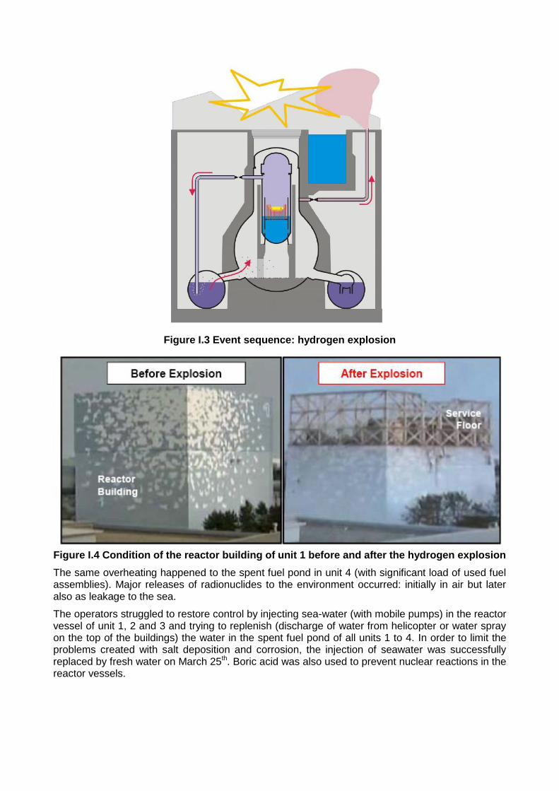
Figure I.3 Event sequence: hydrogen explosion
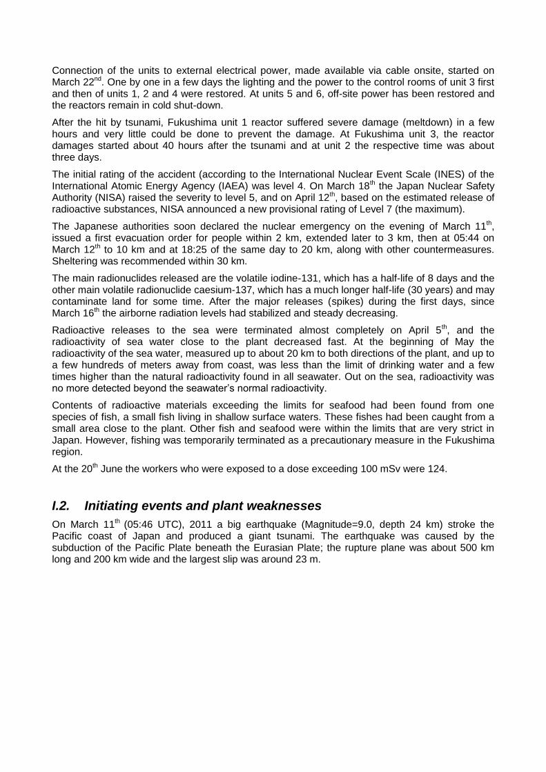
Figure I.4 Condition of the reactor building of unit 1 before and after the hydrogen explosion
The same overheating happened to the spent fuel pond in unit 4 (with significant load of used fuel assemblies). Major releases of radionuclides to the environment occurred: initially in air but later also as leakage to the sea.
The operators struggled to restore control by injecting sea-water (with mobile pumps) in the reactor vessel of unit 1, 2 and 3 and trying to replenish (discharge of water from helicopter or water spray on the top of the buildings) the water in the spent fuel pond of all units 1 to 4. In order to limit the problems created with salt deposition and corrosion, the injection of seawater was successfully replaced by fresh water on March 25th. Boric acid was also used to prevent nuclear reactions in the reactor vessels.
Connection of the units to external electrical power, made available via cable onsite, started on March 22nd. One by one in a few days the lighting and the power to the control rooms of unit 3 first and then of units 1, 2 and 4 were restored. At units 5 and 6, off-site power has been restored and the reactors remain in cold shut-down.
After the hit by tsunami, Fukushima unit 1 reactor suffered severe damage (meltdown) in a few hours and very little could be done to prevent the damage. At Fukushima unit 3, the reactor damages started about 40 hours after the tsunami and at unit 2 the respective time was about three days.
The initial rating of the accident (according to the International Nuclear Event Scale (INES) of the International Atomic Energy Agency (IAEA) was level 4. On March 18th the Japan Nuclear Safety Authority (NISA) raised the severity to level 5, and on April 12th, based on the estimated release of radioactive substances, NISA announced a new provisional rating of Level 7 (the maximum).
The Japanese authorities soon declared the nuclear emergency on the evening of March 11th, issued a first evacuation order for people within 2 km, extended later to 3 km, then at 05:44 on March 12th to 10 km and at 18:25 of the same day to 20 km, along with other countermeasures. Sheltering was recommended within 30 km.
The main radionuclides released are the volatile iodine-131, which has a half-life of 8 days and the other main volatile radionuclide caesium-137, which has a much longer half-life (30 years) and may contaminate land for some time. After the major releases (spikes) during the first days, since March 16th the airborne radiation levels had stabilized and steady decreasing.
Radioactive releases to the sea were terminated almost completely on April 5th, and the radioactivity of sea water close to the plant decreased fast. At the beginning of May the radioactivity of the sea water, measured up to about 20 km to both directions of the plant, and up to a few hundreds of meters away from coast, was less than the limit of drinking water and a few times higher than the natural radioactivity found in all seawater. Out on the sea, radioactivity was no more detected beyond the seawater’s normal radioactivity.
Contents of radioactive materials exceeding the limits for seafood had been found from one species of fish, a small fish living in shallow surface waters. These fishes had been caught from a small area close to the plant. Other fish and seafood were within the limits that are very strict in Japan. However, fishing was temporarily terminated as a precautionary measure in the Fukushima region.
At the 20th June the workers who were exposed to a dose exceeding 100 mSv were 124.
I.2. Initiating events and plant weaknesses
On March 11th (05:46 UTC), 2011 a big earthquake (Magnitude=9.0, depth 24 km) stroke the Pacific coast of Japan and produced a giant tsunami. The earthquake was caused by the subduction of the Pacific Plate beneath the Eurasian Plate; the rupture plane was about 500 km long and 200 km wide and the largest slip was around 23 m.
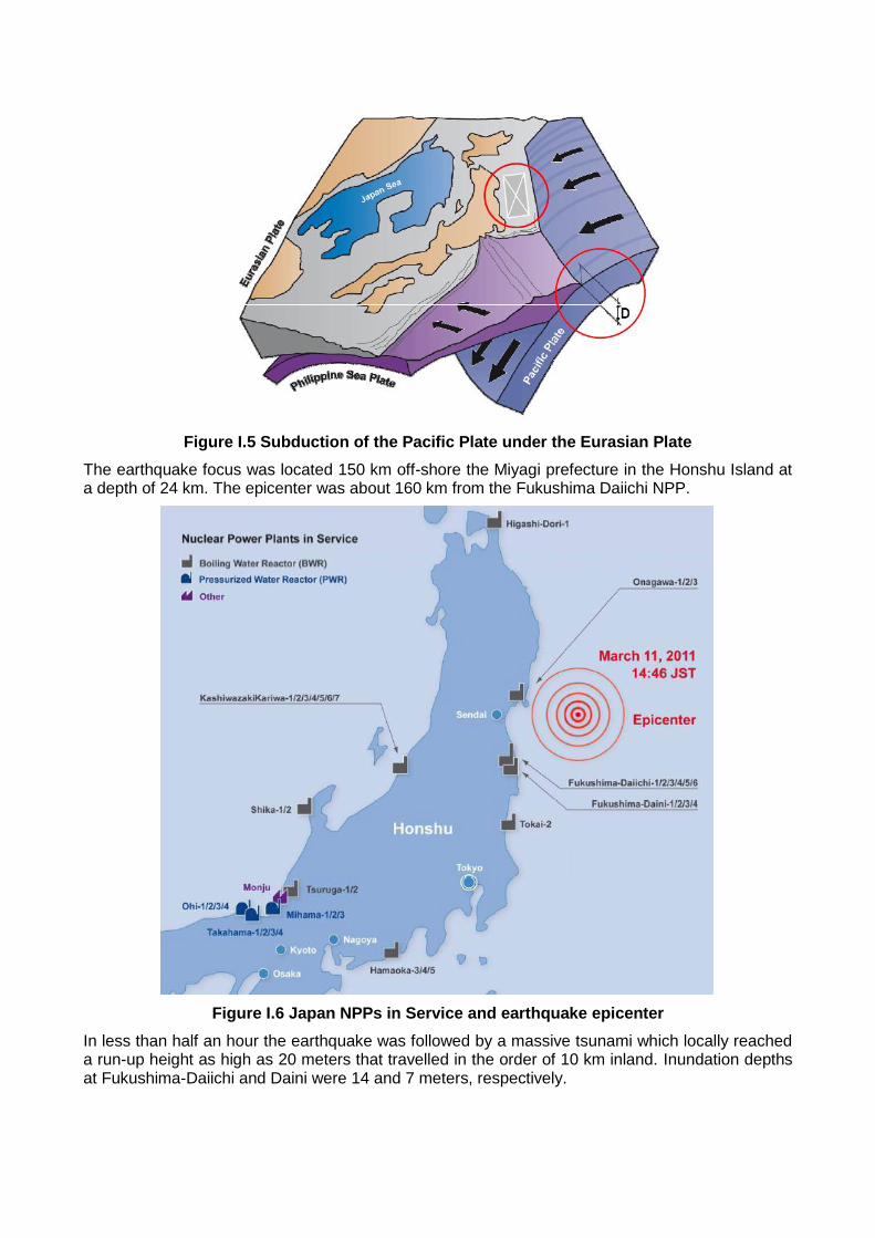
Figure I.5 Subduction of the Pacific Plate under the Eurasian Plate
The earthquake focus was located 150 km off-shore the Miyagi prefecture in the Honshu Island at a depth of 24 km. The epicenter was about 160 km from the Fukushima Daiichi NPP.
Figure I.6 Japan NPPs in Service and earthquake epicenter
In less than half an hour the earthquake was followed by a massive tsunami which locally reached a run-up height as high as 20 meters that travelled in the order of 10 km inland. Inundation depths at Fukushima-Daiichi and Daini were 14 and 7 meters, respectively.
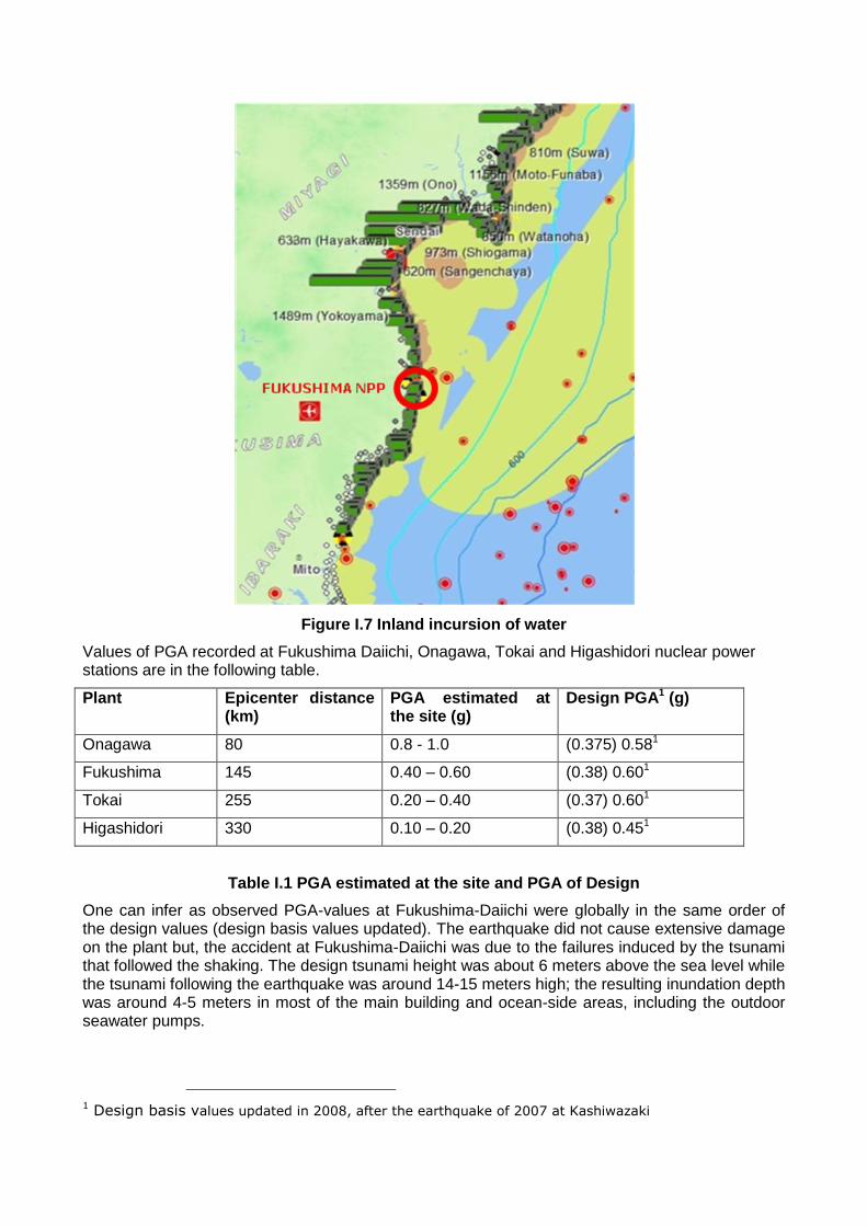
Figure I.7 Inland incursion of water
Values of PGA recorded at Fukushima Daiichi, Onagawa, Tokai and Higashidori nuclear power stations are in the following table.
Plant Epicenter distance (km)
PGA estimated at the site (g)
Design PGA1 (g)
Onagawa 80 0.8 - 1.0 (0.375) 0.581
Fukushima 145 0.40 – 0.60 (0.38) 0.601
Tokai 255 0.20 – 0.40 (0.37) 0.601
Higashidori 330 0.10 – 0.20 (0.38) 0.451
Table I.1 PGA estimated at the site and PGA of Design
One can infer as observed PGA-values at Fukushima-Daiichi were globally in the same order of the design values (design basis values updated). The earthquake did not cause extensive damage on the plant but, the accident at Fukushima-Daiichi was due to the failures induced by the tsunami that followed the shaking. The design tsunami height was about 6 meters above the sea level while the tsunami following the earthquake was around 14-15 meters high; the resulting inundation depth was around 4-5 meters in most of the main building and ocean-side areas, including the outdoor seawater pumps.
1 Design basis values updated in 2008, after the earthquake of 2007 at Kashiwazaki
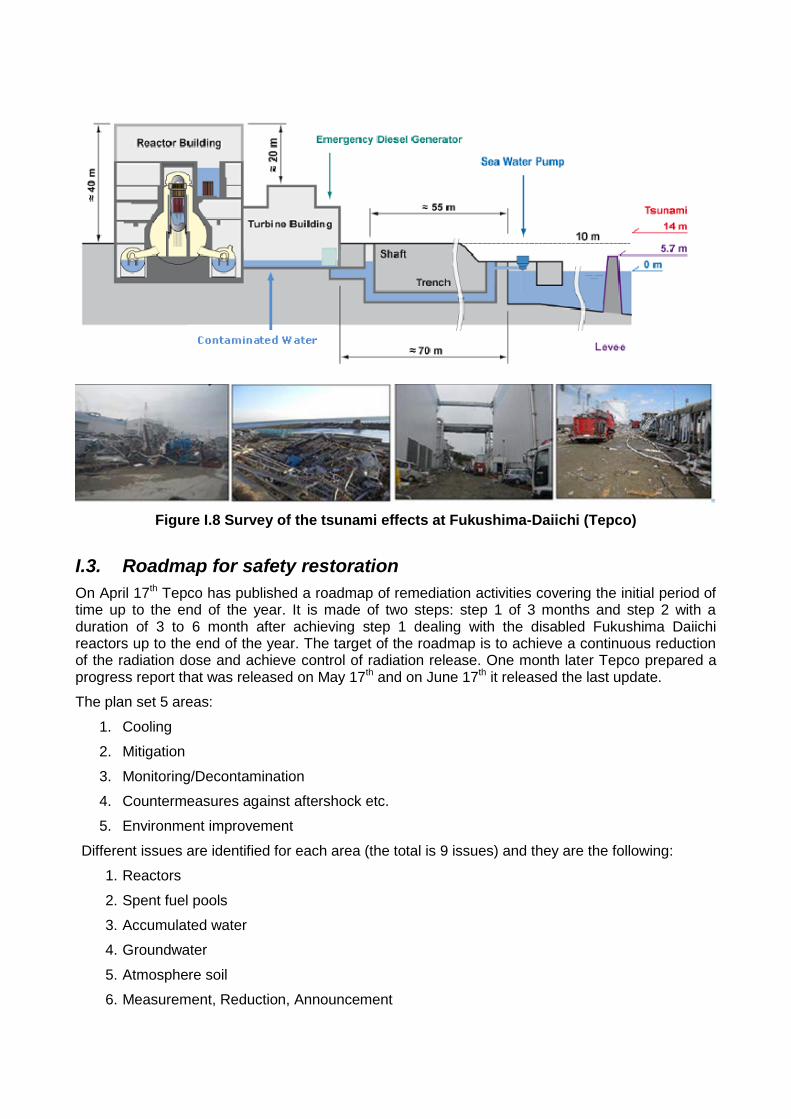
Figure I.8 Survey of the tsunami effects at Fukushima-Daiichi (Tepco)
I.3. Roadmap for safety restoration
On April 17th Tepco has published a roadmap of remediation activities covering the initial period of time up to the end of the year. It is made of two steps: step 1 of 3 months and step 2 with a duration of 3 to 6 month after achieving step 1 dealing with the disabled Fukushima Daiichi reactors up to the end of the year. The target of the roadmap is to achieve a continuous reduction of the radiation dose and achieve control of radiation release. One month later Tepco prepared a progress report that was released on May 17th and on June 17th it released the last update.
The plan set 5 areas:
1. Cooling
2. Mitigation
3. Monitoring/Decontamination
4. Countermeasures against aftershock etc.
5. Environment improvement
Different issues are identified for each area (the total is 9 issues) and they are the following:
1. Reactors
2. Spent fuel pools
3. Accumulated water
4. Groundwater
5. Atmosphere soil
6. Measurement, Reduction, Announcement
7. Tsunami, Reinforcement, etc.
8. Life/work environment
9. Radiation control, Medical care
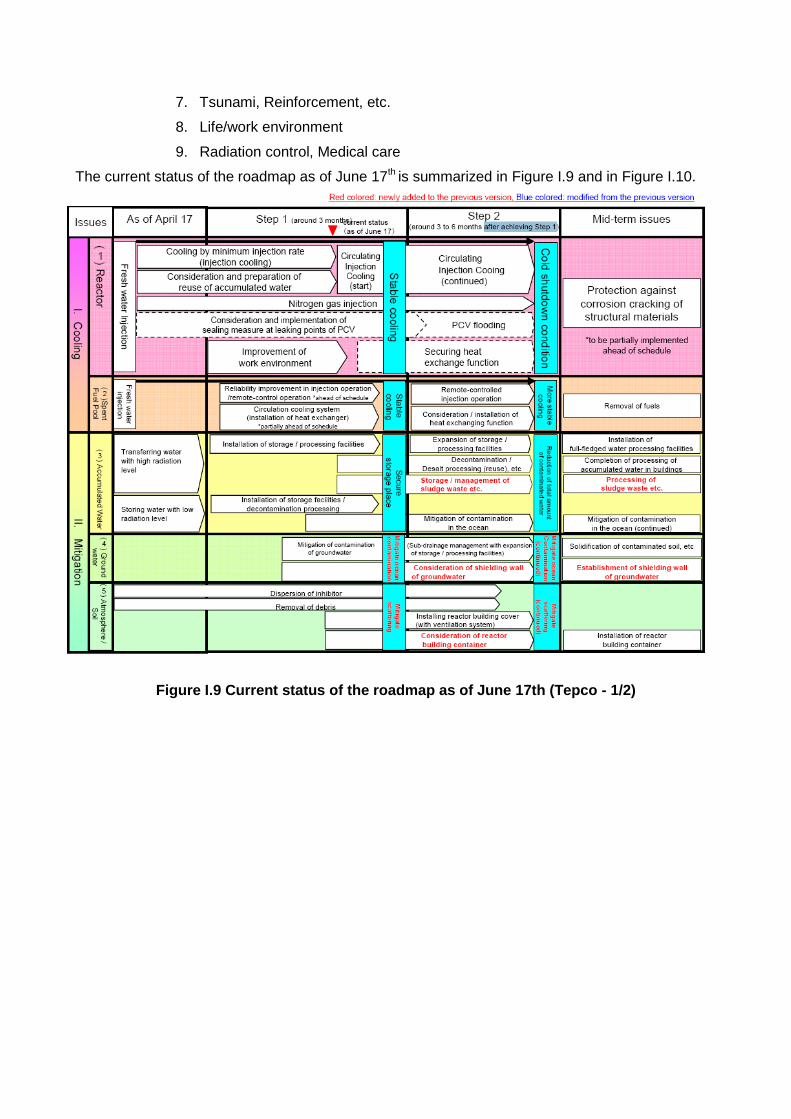
The current status of the roadmap as of June 17th is summarized in Figure I.9 and in Figure I.10.
Figure I.9 Current status of the roadmap as of June 17th (Tepco - 1/2)
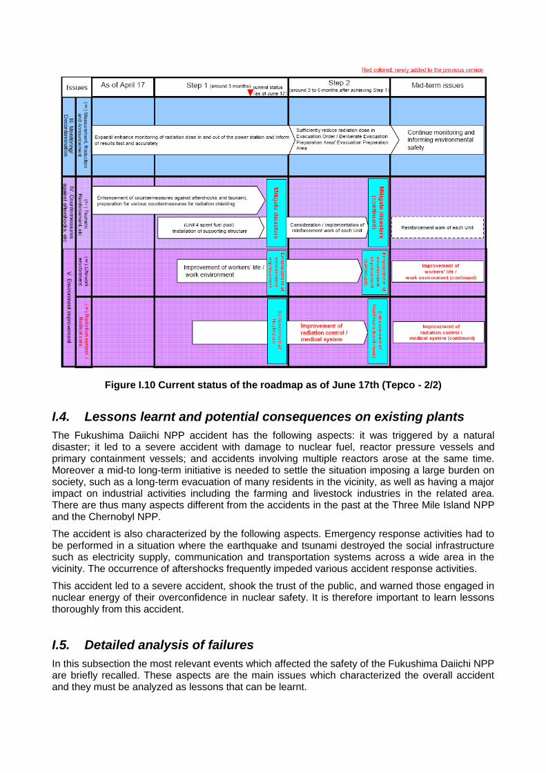
Figure I.10 Current status of the roadmap as of June 17th (Tepco - 2/2)
I.4. Lessons learnt and potential consequences on existing plants
The Fukushima Daiichi NPP accident has the following aspects: it was triggered by a natural disaster; it led to a severe accident with damage to nuclear fuel, reactor pressure vessels and primary containment vessels; and accidents involving multiple reactors arose at the same time. Moreover a mid-to long-term initiative is needed to settle the situation imposing a large burden on society, such as a long-term evacuation of many residents in the vicinity, as well as having a major impact on industrial activities including the farming and livestock industries in the related area. There are thus many aspects different from the accidents in the past at the Three Mile Island NPP and the Chernobyl NPP.
The accident is also characterized by the following aspects. Emergency response activities had to be performed in a situation where the earthquake and tsunami destroyed the social infrastructure such as electricity supply, communication and transportation systems across a wide area in the vicinity. The occurrence of aftershocks frequently impeded various accident response activities.
This accident led to a severe accident, shook the trust of the public, and warned those engaged in nuclear energy of their overconfidence in nuclear safety. It is therefore important to learn lessons thoroughly from this accident.
I.5. Detailed analysis of failures
In this subsection the most relevant events which affected the safety of the Fukushima Daiichi NPP are briefly recalled. These aspects are the main issues which characterized the overall accident and they must be analyzed as lessons that can be learnt.
The issues described in the following are divided in four categories. The first one presents the problems related to the lack of power supply due to the external hazard, the second one presents the difficulties in the emergency response to the event, the third one presents the issues about the severe accident management while the last one is about the plant siting and design.
Emergency power following Beyond Design Basis External Events
o Power supplies
A major cause of this accident was the failure to secure the necessary power supply. This was caused by the facts that power supply sources were not diversified from the viewpoint of overcoming vulnerability related to failures derived from a common cause arising from an external event, and that the installed equipment such as a switchboard did not meet the specifications that could withstand a severe environment such as flooding. Moreover, it was caused by the facts that battery life was short compared with the time required for restoration of the AC power supply and that a time goal required for the recovery of the external power supply was not clear.
o Cooling functions of reactors and PCVs
In this accident, the final place for release of heat (the final heat sink) was lost due to the loss of function of the seawater pumps. Although the reactor cooling function of water injection was activated, core damage could not be prevented due to the drain of the water source for injection and the loss of power supplies, etc., and furthermore, the Primary Containment Vessel (PCV) cooling functions also failed to run well. Thereafter, difficulties remained in reducing the reactor pressure and, moreover, in injecting water after the pressure was reduced, because the water injection line into a reactor through the use of heavy machinery such as fire engines, etc. had not been developed as measures for accident management. In this manner, the loss of cooling functions of the reactors and PCVs aggravated the accident.
o Cooling functions of spent fuel pools
In the accident, the loss of power supplies caused the failure to cool the spent fuel pools, requiring actions to prevent a severe accident due to the loss of cooling functions of the spent fuel pools concurrently with responses to the accident of the reactors. Until now, a risk of a major accident of a spent fuel pool had been deemed small compared with that of a core event and measures such as alternative means of water injection into spent fuel pools, etc. had not been considered.
Emergency response to Beyond Design Basis External Events
o Responses to combined emergencies of both large-scale natural disasters and prolonged nuclear accident
There was tremendous difficulty in communication and telecommunications, mobilizing human resources, and procuring supplies among other areas when addressing the nuclear accident that coincided with a massive natural disaster. As the nuclear accident has been prolonged, some measures such as the evacuation of residents, which was originally assumed to be a short-term measure, have been forced to be extended.
o Environmental monitoring
Currently, local governments are responsible for environmental monitoring in an emergency. However, appropriate environmental monitoring was not possible immediately after the accident because the equipment and facilities for environmental monitoring owned by local governments were damaged by the earthquake and tsunami and the relevant individuals had to evacuate from the Off-site Center Emergency Response Center. To bridge these gaps, the Ministry of Education, Culture, Sports, Science and Technology (MEXT) has conducted environmental monitoring in cooperation with relevant organizations.
o Division of labor between relevant central and local organizations
Communication between local and central offices as well as with other organizations was not achieved to a sufficient degree, due to the lack of communication tools immediately after the accident and also due to the fact that the roles and responsibilities of each side were not clearly defined. Specifically, responsibility and authority were not clearly defined in the relationship between the Nuclear Emergency Response Headquarters and Local Nuclear Emergency Response Headquarters, between the Government and Tepco, between the Head Office of Tepco and the NPS on site, or among the relevant organizations in the Government. Especially, communication was not sufficient between the government and the main office of Tepco as the accident initially began to unfold.
o Communication relevant to the accident
Communication to residents in the surrounding area was difficult because communication tools were damaged by the large-scale earthquake. The subsequent information to residents in the surrounding area and local governments was not always provided in a timely manner. The impact of radioactive materials on health and the radiological protection guidelines of the ICRP, which are the most important information for residents in the surrounding area and others, were not sufficiently explained. Japan focused mainly on making accurate facts publicly available to its citizens and has not sufficiently presented future outlooks on risk factors, which sometimes gave rise to concerns about future prospects.
o Responses to assistance from other countries and communication to the international community
The Japanese Government could not appropriately respond to the assistance offered by countries around the world because no specific structure existed within the Government to link such assistance offered by other countries to the domestic needs. Also, communication with the international community including prior notification to neighboring countries and areas on the discharge of water with low-level radioactivity to the sea was not always sufficient.
o Identification and forecasting of the effect of released radioactive materials
The System for Prediction of Environmental Emergency Dose Information (SPEEDI) could not make proper predictions on the effect of radioactive materials as originally designed, due to the lack of information on release sources. Nevertheless, the Ministry of Education, Culture, Sports, Science and Technology (MEXT), the Nuclear and Industrial Safety Agency (NISA) and the Nuclear Safety Commission (NSC) Japan used SPEEDI to calculate the estimation with various assumptions for the internal examination of the situation. Even under such restricted conditions without adequate information on release sources, it should have been utilized as a reference of evacuation activities and other purposes by presuming diffusion trends of radioactive materials under certain assumptions, but it could not. Although the results generated by SPEEDI are now being disclosed, disclosure should have been conducted from the initial stage.
o Definition of widespread evacuation areas and radiological protection guidelines in nuclear emergency
Immediately after the accident, an Evacuation Area and In-house Evacuation Area were established, and cooperation of residents in the vicinity, local governments, police and relevant organizations facilitated the fast implementation of evacuation and “stay-in-house” instruction. As the accident became prolonged, the residents had to be evacuated or stay within their houses for long periods. Subsequently, however, it was decided that guidelines of the ICRP and IAEA, which have not been used before the accident, would be used when establishing Deliberate Evacuation Area and Emergency Evacuation Prepared Area. The size of the protected area defined after the accident was considerably larger than 8 to 10 km radius, which had been defined as the area where focused protection measures should be taken.
o Training responding to severe accidents
Effective training to respond to accident restoration at nuclear power plants and adequately work and communicate with relevant organizations in the wake of severe accidents was not sufficiently implemented up to now. For example, it took time to establish communication between the emergency office inside the power station, the Nuclear Emergency Response Headquarters and the Local Headquarters and also to build a collaborative structure with the Self Defense Forces, the Police, Fire Authorities and other organizations which played important roles in responding to the accident. Adequate training could have prevented these problems.
o Human resources for the accident management
After the accident a significant fraction of the local staff had been killed or injured by the earthquake and tsunami so that there were some concerns about the possibility of ensuring proper staffing throughout the accident.
Severe accident management
o Hydrogen explosions
In the accident, an explosion probably caused by hydrogen occurred at the reactor building in Unit 1 at 15:36 on March 12th, 2011, as well as at the reactor in Unit 3 at 11:01 on March 14th. In addition, an explosion that was probably caused by hydrogen occurred at the reactor building in Unit 4 around 06:00 on March 15th, 2011. Consecutive explosions occurred as effective measures could not be taken beginning from the first explosion. These hydrogen explosions aggravated the accident. A BWR inactivates a PCV and has a flammability control system in order to maintain the soundness of the PCV against design basis accidents. However, it was not assumed that an explosion in reactor buildings would be caused by hydrogen leakage, and as a matter of course, hydrogen measures for reactor buildings were not taken.
o Containment venting system
In the accident, there were problems in the operability of the containment venting system. Also, as the function of removing released radioactive materials in the containment venting system was insufficient, the system was not effective as an accident management countermeasure. In addition, the independence of the vent line was insufficient and it may have had an adverse effect on other parts through connecting pipes, etc.
o Accident response environment
In the accident, the radiation dosage increased in the main control room and operators could not enter the room temporarily and the habitability in the main control room has decreased, and it remained difficult to work in that room for an extended period. Moreover, at the on-site emergency station, which serves as a control tower for all emergency measures at the site, the accident response activities were affected by increases in the radiation dosage as well as by the worsening of the communication environment and lighting.
o Radiation exposure management system at the time of the accident
As these accidents occurred, although adequate radiation management became difficult as many of the personal dosimeters and dose reading devices became unusable due to their submergence in seawater, personnel engaged in radiation work had to work on site. In addition, measurements of concentration of radioactive materials in the air were delayed, and as a result the risk of internal exposure increased.
o Instrumentation to identify the status of the reactors and PCVs
Because the instrumentation of the reactors and PCVs did not function sufficiently during the severe accident, it was difficult to promptly and adequately obtain important information to identify how the accident was developing such as the water levels and the pressure of reactors, and the sources and amounts of released radioactive materials.
Plant Siting and Design
o Measures against earthquakes and tsunamis
The earthquake was an extremely massive one caused by linked seismic centers. As a result, at the Fukushima Daiichi NPP, the acceleration response spectra of seismic ground motion observed on the base mat exceeded the acceleration response spectra of the design basis seismic ground motion in a part of the periodic band. Although damage to the external power supply was caused by the earthquake, no damage caused by the earthquake to systems, equipment or devices important for nuclear reactor safety at nuclear reactors has been confirmed.
The tsunamis which hit the Fukushima Daiichi NPP were 14-15 m high, substantially exceeding the height assumed under the design of construction permit or the subsequent evaluation. The tsunamis severely damaged seawater pumps, etc., causing the failure to secure the emergency diesel power supply and reactor cooling function. The procedural manual did not assume flooding from a tsunami, but rather only stipulated measures against a backrush. The assumption on the frequency and height of tsunamis was insufficient, and therefore, measures against large-scale tsunamis were not prepared adequately.
o Accident management measures
The accident reached the level of a so-called “severe accident.” Accident management measures had been introduced to the Fukushima NPP to minimize the possibilities of severe accidents and to mitigate consequences in the case of severe accidents. However, looking at the situation of the accident, although some portion of the measures functioned, such as the alternative water injection from the fire extinguishing water system to the reactor, the rest did not fulfill their roles within various responses including ensuring the power supplies and the reactor cooling function, with the measures turning out to be inadequate. In addition, accident management measures are basically regarded as voluntary efforts by operators, not legal requirements, and so the development of these measures lacked strictness. Moreover, the guideline for accident management has not been reviewed since its development in 1992, and has not been strengthened or improved.
o Site with more than one reactor
The accident occurred at more than one reactor at the same time, and the resources needed for accident response had to be dispersed. Moreover, as two reactors shared the facilities, the physical distance between the reactors was small. The development of an accident occurring at one reactor affected the emergency responses at nearby reactors.
o NPP arrangement in basic designs
Response to the accident became difficult since the spent fuel storage pools were located at a higher part of the reactor buildings. In addition, contaminated water from the reactor buildings reached the turbine buildings, meaning that the spread of contaminated water to other buildings has not been prevented.
o Water tightness of essential equipment facilities
One of the causes of the accidents is that the tsunami flooded many essential equipment facilities including the component cooling seawater pump facilities, the emergency diesel generators, the switchboards, etc., impairing power supply and making it difficult to ensure cooling systems.
o Independence and diversity of safety systems
Although multiplicity has been valued until now in order to ensure the reliability of safety systems, avoidance of common cause failures has not been carefully considered and independence and diversity have not been sufficiently secured.
o Effective use of probabilistic safety assessment (PSA) in risk management
PSA has not always been effectively utilized in the overall reviewing processes or in risk reduction efforts at nuclear power plants. While a quantitative evaluation of risks of quite rare events such as a large-scale tsunami is difficult and may be associated with uncertainty even within PSA, Japan has not made sufficient efforts to improve the reliability of the assessments by explicitly identifying the uncertainty of these risks.
I.6. Potential upgrading measures on existing plants
The Fukushima accident forces the international community to reflect on the accident and on the actual safety of existing NPPs in the light of the events which challenged the Fukushima. The considerations made lead to the definition of the concept of “Stress Test” as a targeted reassessment of the safety margins of nuclear power plants in the light of the events which occurred at Fukushima: extreme natural events challenging the plant safety functions and leading to a severe accident (ref. WENRA). The results of these reassessment processes of the safety margins against beyond design basis events could lead to modifications of the plants, for what concerns components and procedures, in order to make them compliant with the safety requirements against extreme external hazards challenging the plant and severe accident.
In this subsection the potential consequences of the Fukushima Daiichi accident (i.e. of the stress test activities) on the existing plants in the world are discussed. These consequences consist in a set of preventive and mitigating actions that could be implemented on the existing plants in relation to some considered scenarios. In particular these scenarios which are taken into account are the following ones (ref. WENRA).
1. The Station Blackout (SBO).
2. The Loss of the Ultimate Heat Sink (LUHS).
3. The Station Blackout and the Loss of the Ultimate Heat Sink (SBO/LUHS).
4. The Severe Accident scenario (SA).
For what concerns the scenarios from 1 to 3 of the list above the consequences consist in set of preventive actions to implement; obviously, for the severe accident scenario (n. 4) mitigating actions could be necessary. The scope of these actions are the more critical source terms of a plant, i.e. the reactor and the spent fuel pool (SFP), which were responsible of the radioactivity releases in the Fukushima Daiichi accident.
Station Blackout (SBO)
The first considered scenario is the complete station blackout. In the case of SBO scenario the strategies to be mainly considered are the ones which allow the power supply needed to guarantee the required safety functions.
o AC and DC power recovery
In the specific, the recovery of AC power supply could be guaranteed by providing:
an off-site portable diesel generator;
an onsite gas turbine generator;
an onsite SBO Diesel;
and by inspecting the equipment and validating the procedures for a potential operating 3rd source of own consumption (for instance hydroelectric power plant).
For what concerns the DC power supply, it could be provided by providing:
alternate portable batteries stored offsite;
alternate installed batteries.
o Extension of the duration of AC and DC power
The extension of the duration of AC and DC power could be made my means of load shedding and management.
The AC power duration could be also extended by refueling of the Emergency Diesel.
o Protection of the emergency safety systems areas
It could be done by verifying the operability of diesel generator for leaking and flooding of rooms placed below ground level.
o Protection of the surveillance and monitoring functions
Externally available measurement connections for level, pressure, temperature, hydrogen content should be provided.
As specific strategy, DC power supplies to allow depressurization of RPV and injection with portable pump could be implemented.
Loss of Ultimate Heat Sink (LUHS)
The second considered scenario is the loss of ultimate heat sink, crucial aspect for assuring the cooling of all the plant heat source terms, i.e. the core and the spent fuel pool.
In the case of LUHS scenario the strategies to be mainly considered are the ones which allow the cooling recovery.
o Core cooling recovery
The measures which could be implemented to recover the core cooling availability are the provision of:
fire water connection for RPV/SG injection;
condensate Storage Tank (CST) / Auxiliary Feed-water Storage Tank (AFWST) to refill capability by cross-ties to onsite water systems (e.g. fire protection water, domestic water, etc.);
condensate Storage Tank (CST) / Auxiliary Feed-water Storage Tank (AFWST) to refill capability by offsite supplies (e.g. fire pumper truck);
Against flooding hazard, the use of flood proof motors could be provided.
For PWRs it could be provided a large volume makeup source to the reactor water storage tank RWST (or equivalent) in order to extend the supply of water for core cooling and a system to manually depressurize the Steam Generators (opening atmospheric dump valves, i.e.) in order to reduce its pressure and Reactor Cooling System temperature/pressure.
o Spent fuel pool cooling recovery
In the specific, the possible provisions are practically the same used for the core cooling listed above.
o Room cooling recovery
It could be implemented by providing alternate cooling water source to room coolers (e.g., fire water).
o Component cooling recovery
It is possible to:
provide alternate component cooling water source to key components;
utilize intermittent component operation and/or rotate component operation to provide cool down;
replace of key components with self-cooled or air cooled versions.
o RCP Seal cooling recovery
It could be done by providing an alternate cooling water supply for charging pumps, an alternate thermal barrier cooling for RCP seals and by installing air-cooled charging pumps.
o Emergency diesel generator cooling recovery
It could be attempted by providing:
procedural direction to trip EDGs;
fire water connection to service water system to cool EDGs;
on-site fire pumper truck hookup to the service water system;
off-site water supply capability to the service water system;
off-site fire pumper truck hookup to the service water system;
or by replacing/adding air-cooled EDG.
Station Blackout and Loss Of Ultimate Heat Sink (SBO+LUHS)
The third case considered is the combined scenario of Station Blackout and Loss of Ultimate Heat Sink.
o Core cooling recovery
The possible measures are:
the use of external pumps
the provision an external tank cooling the core by gravity (passive cooling)
o Spent fuel pool cooling recovery
Also in this case the possible measures are the same for the core (external pumps, external tank for passive cooling) but it could be also provided an alternate SFP water cooling, like a portable exchanger or something similar.
o Room cooling recovery
It could be done by providing alternate room cooling via local actions (e.g., open doors, portable fans).
o Protection of emergency safety systems areas
Considering the external event of flooding, the following actions could be performed:
inspection of areas where there are emergency safety systems (including electrical switch rooms of emergency power supply) and check of their department in terms of a possible spread of external flooding (closure of doors) as a source of flooding;
verification of the status of barriers (doors, thresholds) to prevent penetration of water from neighboring areas to inspected room;
safety walk to verify the passage of storm drains (drains clogging) and objects around inlets, which they could stop up and examination of the status of barriers (doors, thresholds) to prevent water penetration from outside into rooms;
development of instructions on how to proceed in case of flooding of critical rooms, eventually flooding of technology channels;
extension of the plant waterproof.
o Maintaining of SFP water level
This objective could be reached by providing a spray to the SFP using a portable, power independent pumping capability.
o Addition of Site specific SFP makeup strategies
A review of all NRC strategies and of the list of the viable strategies in plant procedures/guidance could be done.
o Management and control enhancements
The possible actions are:
the provision of a guidance for operations following interruption of the normal control and command structures;
the assessment of on-site and off-site communication in light of potential damage to normal methods available to the Emergency Response Operation (ERO);
introduction of methods for notifications of the utility ERO activation to mobilize additional resources to the site in a timely manner;
identification of basic initial response actions needed to potentially stabilize the situation or delay event degradation, including key mitigation strategies to help manage critical safety functions in the near term;
assessment of initial damage to provide the ERO with information on plant damage conditions and status.
Severe accident
The last considered scenario is the severe accident scenario.
In this case, the mitigating strategies individuated in the light of the Fukushima accident are the listed in the following.
o Reduction of the risk of hydrogen explosion
This task can be achieved by improving containment venting and by providing (more) hydrogen recombiners.
o Reduction of the pressure in the containment
It could be achieved by containment venting.
o General management of the severe accident
The revision of procedures taking into account the other units on site could be done and it could be set up an offsite reactor plant control center (remote).
o Ensuring the emergency core cooling
The key valves for emergency core cooling could be identified and it could be required that they do not be electrically activated.
o External cooling of the reactor pressure vessel
Measures enabling prompt flooding of reactor cavity (for instance with portable pump, etc…) could be introduced together with the installation of “Siphon” in ventilation ducts leading into the reactor cavity. Moreover, modifications ensuring flow of coolant/two phase flow around reactor vessel into steam generator compartment could be provided.

o Control of the depressurization of the RCS
The reliability of RCS depressurization paths could be increased.
o Prevention of excessive negative pressure in containment
It could be done by installing a vacuum breaker.
o Provision of information and other means for application of SAMGs
There is a need of adequate data transfer into Technical Support Center as required for the SAMGs usability.
Appendix II Methodology of stress tests
II.1. Deterministic assessment of fulfilment of safety functions – configuration matrix approach
Methodology for assessment of four safety functions is based on application of defence in-depth (Levels 3 and 4) for NPP conditions evoked by beyond-design basis external natural events (BDB EE) or their causal combination. The safety functions to be maintained are:
Reactor core subcriticality;
SFP subcriticality;
Heat removal from the reactor core;
Heat removal from the spent fuel pool (SFP);
Containment integrity (= heat removal from containment + containment isolation + prevention of high-energy internal phenomena related to hydrogen generation).
Systematic assessment of the NPP response to beyond-design basis external events and their potential combinations with an impact on long-term development of severe conditions and identification of cliff-edge effects at supporting functions (AC and DC power supply, ESW cooling etc.) and by them individual safety functions themselves exceeds possibilities of existing information sources (procedures, safety reports, PSA Level 1 and 2, specific safety analyses supporting EOP/SAMG etc.). Analyses available for assessment of defence in depth in transitions from level 3 to level 4 should consider to various extent not only safety systems but also normal operation systems. From the viewpoint of EE impact on serviceability of systems, until now only design basis events were considered and qualification of components was also assessed only for the design basis events. Thus, adequate information about the NPP response to BDB EE and to internal initiating events evoked by the BDB EE is missing.
Therefore stress tests defined as assessment of the NPP vulnerability (or vulnerability of selected safety functions) at the BDB EE conditions must be preceded by systematic assessment of vulnerability of those key normal operation system components and safety system components, which are ensuring fulfilment of safety functions during an even initiated by a hypothetical BDB EE. This analysis must be performed for all operation regimes. Loss of serviceability of key components will cause the loss of serviceability of the respective system thus reducing a level of redundancy or complete loss of ability to fulfil some of critical safety functions. It should be underlined that if both normal operation systems as well as safety systems are considered as available for the defence in depth protection levels 3 and 4, the initial redundancy of assurance of systems for performing safety functions is relatively high as can be seen from procedures for normal operation and in particular from EOP.
The assessment of vulnerability of critical safety functions for the NPP as a whole can be derived from the assessment of vulnerability of key components, systems and structures (SSCs) only if the external event will not evoke a significant internal event having its own progression as an independent failure.
For instance in case of strong beyond-design basis earthquake, serviceability of systems for heat removal from the core/SFP and systems needed for subcriticality control may be affected/lost, or an induced leak of the primary circuit or SFP may occur. In such case, it would be necessary to examine also other aspects affecting safety of the reactor core, of the containment or the SFP, at least from viewpoint of ability to ensure critical safety function “Coolant inventory control”. However, such complex assessment of combined events would require more comprehensive safety analyses.
Therefore the stress tests do not cover a possibility of occurrence of induced internal events due to the BDB EEs or their combination. The only considered mechanism of endangering safety functions are losses of serviceability of systems protecting the safety functions. From the viewpoint of phenomenological development of events, it is the transient type event, i.e. event with “violation with heat removal” or event “loss of subcriticality/secondary criticality”.
Assessment of cliff edges of effects, recovery actions and their feasibility, stages of event development and time margins must be based on realistic conditions evoked by the hypothetical external event. Key components / systems / structures are affected either directly (e.g. failure due to flooding) or indirectly (e.g. by loss of power supply or other supporting functions).
The existing PSA studies for EBO V2 and EMO 12, in particular due to limited consideration of normal operation systems, does not enable identification of all redundant combinations of SSCs, available for maintaining considered safety functions for short time or temporary at least. The main reason is application of the principle of minimum required ability to fulfil the function, the so called “mission time” for 24 hours at least.
Thus, the stress test analyses must be based on the deterministic basis and they must have at disposal suitable, for this purpose optimised, supporting tools.
Requirements put on the supporting deterministic system (database), enabling to identify all the key SSCs sets and based on its significance to evaluate the BDB EE impact on key NPP components and thus to monitor residual serviceable sets of the components ensuring critical safety functions can be summarised as follows:
Database must be a tool enabling systematic and well-arranged monitoring/assessment of serviceability of combinations of key components ensuring the particular safety function. Within this methodology, the term “configurations” is introduced for these combinations and these configurations form a “configuration matrix” consisting of individual SSCs included.
Vulnerability of components (and also configurations) is assessed realistically by comparison of identified or estimated margins in relation to loads induced by environmental conditions, such as seismic loads, temperature and humidity, and as well by assessment of availability of supporting functions such as power supply, cooling etc..
The assessment covers all the realistically applicable or realistically adjustable configurations, specifically for all the NPP operation regimes.
Gradual deterministic increase of severity (loading) due to the BDB EE and assessment of impacts on serviceability of configurations until all the configurations ensuring at least conditionally and time-limited maintaining the particular safety function are lost.
The configurations are identified based on normal operation procedures, safety reports (addressing design basis events by conservatively considered actions of safety systems – defence in depth protection at the 3rd level) and EOPs (design basis events and BDBA events addressed realistically – transition between levels 3 and 4 of defence in depth). Since the SAMG implementation is not yet finished in full scope, configurations at the defence in depth protection level 4 have not been considered. Management of severe accidents will be addressed separately.
II.2. Development of the database
The database summarizing information needed for assessment of serviceability of plant key components has been developed in the following steps:
1. Identification of all SSCs configurations – identification of all existing SSCs connections enabling to maintain the particular safety function temporarily at least. Time interval, during which the configuration can ensure the function, belongs to assessed parameters. Each configuration is defined by minimum SSCs set, sufficient for maintaining the safety function,
e.g. tanks, pumps, pipes, valves, heat exchangers etc. The configurations are identified for all operational regimes and for all safety functions.
Note 1: No minimum time limit for the required serviceability is applied, such as for instance “mission time” in PSA studies.
Note 2: Configurations for beyond-design basis external conditions are selected mainly in accordance with symptom-based EOPs. It should be emphasised that EOPs as a relatively high-level document do not contain all details regarding the configurations and potential recovery actions, etc. so that engineering judgment and operational experience are needed for completing the required information.
Note 3: Many basic configurations can be set, thus providing big space and flexibility for their consideration if their serviceability is not affected. Number of potential strategies for maintaining or recovery of safety functions markedly exceeds the number of “front-line” strategies involved in PSA L1 or in conservative safety analyses, based on utilisation of only safety systems.
2. Identification of configurations of supporting systems of SSCs systems ensuring power supply and other supporting functions (cooling, supply of media, etc.) grouped and considered analogically as in case of systems directly fulfilling safety functions
Note: For practical reasons, operation regimes are subdivided into 3 groups:
Assessment of reactor core safety functions
Power operation – semi-hot condition
Cold shut-down, reactor vessel closed
Cold shut-down, reactor vessel open for refuelling
Assessment of spent fuel pool safety functions
Reactor vessel separated from the spent fuel pool (during power operation or during refuelling)
Reactor vessel interconnected with the spent fuel pool during refuelling
Maintaining the safety functions for the SFP as compared to the reactor core is ensured by a separate group of configurations for majority of operating regimes, except for the time limited interval during refuelling, when some safety functions can be controlled together with the relevant safety functions from the reactor core (e.g. heat removal).
3. Estimation of capacity of individual configurations, i.e. realistic estimation of time, during which the configuration can perform its function and setting of conditions of usability of a given configuration (with regard to previous development of situation, unit operating regime, relevant technical limitations etc.).
Note: Individual groups of configurations differ markedly from the viewpoint of capacity of sources (e.g. flow rate of media and total coolant inventory), from the viewpoint of “robustness” (number and qualification of individual components) and margins for the respective operation regime (demand/capacity balance).
4. Compilation of a list of all key components (listing of all components, present at least in one configuration).
Note: The list of components is compiled in parallel with identification and estimation of capacities of these configurations.
5. Identification of quantitative characteristics with re–assessment of vulnerability of components included in the list of key components, i.e. identification (using published data, engineering judgment, analysis, etc.) of all characteristics, which are determining for assessment of the BDB EE impact on NPP systems (vulnerability parameters).
Note 1: Characteristics and margins resulted from them are systematically retrieved in existing documentation (e.g. existing seismic data for the seismic island and other systems, qualification data presented in system specifications, etc.), found out during site walk-down (e.g. vertical margins of components before to be flooded), estimated by engineering judgment, etc.
Note 2: Quantitative representative characteristics of components in relation to the BDB EE include:
Position (building, floor, room)
Power supply – all levels including stand-by
Level of water for flooding (height from room floor, qualification against moisture/direct contact with water, resistance against flooding etc.)
Seismic data (acceleration, seismic qualification etc.)
Maximum /minimum temperature in the room (temperature limitation from the component viewpoint)
Controllability (of valves) – from the main control room, emergency control room, in-situ, from switchboard
Supporting functions necessary for component operation (cooling, lubrication, compressed air)
6. Arranging of configurations into groups – arranging of configurations into groups with similar capacity margins with regard to particular safety function, with the objective to improve transparency of the database and its outputs
7. Verification of configurations – verification of the database of configurations from the viewpoint of its completeness, verification of component parameters representing their vulnerability at BDB EE, estimation of configuration capacities etc.
8. Development of suitable database user interface – optimisation of interface with regard to expected inputs and outputs
II.3. Application of the database for assessment
The consecutive steps in application of the database are as follows:
1. Definition of BDB EE significance: BDB EE or combinations are inserted into the database in terms of quantified parameters representing severity of the main impact on NPP systems as a deterministic input
2. Identification of configurations available for ensuring safety functions by means of automatic assessment of failed SSCs: the database will exclude configurations with margins exceeded in case of some SSC for the given BDB EE severity parameters, or with SSC with lost supporting functions.
Note 1: In this step, a list of serviceable configurations is generated as well as a list of potentially recoverable configurations (configurations with low number of failed components, which can be recovered by AM actions).
Note 2: In this step, time interval/window, during which the available configurations ensure safety functions, is assessed, and the time sequence of cliff edges with increasing severity of the BDB EE is determined.
3. Analysis of potential recovery actions and need of hardware implementation: by iteratively repeating steps 1 and 2 in addition to vulnerability of components also possibilities of staff actions within accident management are assessed, i.e. feasibility of recovery actions for putting the configurations into serviceable condition under realistic conditions of the BDB EE of given

severity, availability of resources and logistic support, and possibility/necessity of hardware modifications or installation of new hardware are assessed. These assessments are based on engineering judgment and existing information sources.
4. Identification of the ultimate BDB EE for the given safety function: by means of stepwise increase of severity of the BDB EE in the loop formed by steps 1 and 3 it is possible to determine, at which BDB EE parameters the ability to fulfil the particular safety function in the given NPP operation regime is unconditionally lost, since for such severity all the configurations are non-serviceable and unrecoverable.
37
Appendix III Methodology of stress tests for MO 34
III.1. General description of methodology
The purpose of this appendix is to present the approach which has been adopted for the evaluation of MO 34 margins against:
o Beyond-Design-Basis (BDB) earthquake,
o BDB flooding,
o BDB extreme natural events and their combinations.
In this way, a Safe Shutdown Path (SSP) has been identified for subsequent margin evaluation for all the above-mentioned external hazards. The SSP is a list of structures, systems and components (SSCs) of one unit which represents the reference minimal combination of equipment needed to preserve, at least for 72 hours and without off-site support, the fundamental safety functions for prevention of core damage on the unit, i.e.:
a. core sub-criticality;
b. core decay heat removal;
c. spent fuel pool (SFP) sub-criticality;
d. SFP heat removal;
e. confinement of radioactivity.
The SSP has been identified for Unit 3 (the results being fully applicable to Unit 4) for each of two plant operating modes which have been deemed as enveloping all the plant operating modes (i.e., full-power and open-reactor mode).
The margin of the plant against a defined external threat corresponds to the margin of the most vulnerable of the items included in the SSP, as it is assumed that the loss of one item of the SSP list induces the loss of the whole SSP.
It has to be highlighted that this approach is conservative, as:
the selected SSP, in general, is not the combination of SSCs having the highest resistance against a specific hazard; in this sense, the calculated margin has rather to be regarded as a lower bound of the real NPP resistance against the considered hazard;
the loss of one SSP item in general can be mitigated by proper operator actions, which however are not considered in the present analysis.
In the SSP, active/passive components are included: in addition, even if piping is not included in the SSP list, it is intended that the resistance of the piping on which SSP items (e.g. valves, pumps, tanks, etc.) are installed is properly taken into account in the analyses.
The SSP has been defined on the basis of the following main criteria:
the SSP has been identified as a subset of the equipment available to bring the unit to cold shutdown conditions after an earthquake. In this way, all the SSCs belong to SSP are seismically qualified;
the whole primary circuit (i.e., six loops) is taken into account in the analyses and hence all the valves needed to isolate primary circuit after an earthquake are considered in the SSP list (with the exceptions discussed below), although only two primary loops are assumed as operational for heat removal (i.e., via emergency feedwater + SG relief valves). Loop 1 and 6 are selected, as PRZR is connected to loop 1;
38
pipe lines of diameter ≤ 25 mm (i.e. including all impulse lines and minor connections to primary loops) are not assumed as critical and hence are not considered in the analyses;
the electrical equipment taken into account for the analyses consists of the following (seismically-qualified) safety-related components:
switchboards;
accumulator batteries together with rectifiers and inverters;
6/0.42 kV transformers.
cables (together with seismically-qualified cable trays) and circuit breakers are assumed as non critical and hence are not considered in the analysis.
the I&C equipment taken into account for the analyses includes all the seismically-qualified cabinets and the seismic-resistant panels of MCR/ECR (although, in principle, not all cabinets are needed to be included in the SSP).
as for the electrical part, I&C cables (together with cable trays) are not considered in the analysis because assumed as non-critical;
civil structures housing SSP items are taken into account in the analyses.
in the analysis of the margins, SSCs seismically categorized as “2a” are not included in the SSP, for the following reasons:
the qualification as 2a, rather than 2b, is purely based on layout reasons (i.e., possible post-earthquake interaction with category-1 equipment).Although a preliminary categorization of plant equipment into seismic categories was done within the revision of Basic Design, such categorization can be significantly altered before completion of construction activities;
in Detail Design, for such systems/components in general there may not be any specific calculation to assess the precise seismic margins, since their functionality is not requested after the earthquake;
evaluation of measures to eliminate the risks of seismic interactions will be identified also in future stages of construction, and therefore an assessment at this stage would be certainly partial and of little practical use.
Once the SSP has been identified, the margins of each SSCs were assessed and included into SSP on the basis of the Detail Design documentation currently available in MO34 and/or applicable reference documentation. For this purpose the following hierarchy of design source documentation was used:
1. MO34 Detail Design documentation ;
2. MO34 approved Basic Design documentation and MO34 PRESAR;
3. MO34 documentation which is under development within the project of MO34 completion (MO34 EOPs, MO34 PSA Level 1);
4. EMO12 Design and licensing documentation.
Once the SSP has been identified, the margins of each SSCs were assessed and included into SSP on the basis of the Detail Design documentation currently available in MO34 and/or applicable reference documentation. For this purpose the following hierarchy of design source documentation was used:
1. civil structures;
2. mechanical equipment;
39
3. electrical equipment;
4. I&C equipment.
III.2. Application of methodology to earthquakes
Civil structures
The original Design Basis Earthquake for MO 34 (as for EMO 12) is associated with a PGA = 0.06g. However, when granting an exclusion from the construction permit for MO34, UJD defined for Mochovce seismic qualification (RLE) with PGA = 0.15g.The structural analyses performed within the Basic Design (BD) have verified the requalification of these civil structures to the level requested by UJD SR, they have been representing the minimal reserve existing with consideration the design basis value since then. A more precise assessment of the ultimate resistance of the civil structures would require elasto-plastic analyses which are currently not available.
Mechanical equipment
Stress-analyses calculation reports for seismically qualified systems were performed in line with the relevant requirements and each report presents HCLPF coefficients for evaluated SSC/branch. Coefficient HCLPF characterizes the mathematical failure probability distribution (failure probability is 5%, confidence level 95%)
The definition, and consequently the calculation, of the HCLPF is made following the CDFM (Conservative Deterministic Failure Margin) approach, as described in EPRI NP-6041-M.The following formula has been considered:
Where:
C is the capacity of SSC and the specified standard;
DS is the seismic demand for SSC estimated according with CDFM criteria;
DNS is the concurrent non-seismic demand for all non-seismic loads in the load combination;
SME is the RLE seismic input in terms of PGA (i.e., 0.15g).
Furthermore, it is considered that for piping and for support structures usually a plastic deformation could be accepted, hence introducing an inelastic energy absorption factor FU.
Electrical equipment
The electrical equipments identified in the SSPs are qualified either by tests or by analyses:
For components qualified by test, margins are evaluated by comparing the Smoothed Floor Response Spectra (FRS), at the floor in which such equipment is positioned, and the Test Response Spectra (TRS).The comparison was done for all three axes – x, y, z. The ratio between the two spectra has been considered at each frequency, and the minimum ratio has been taken as the available margin.
For components qualified by analysis, the margin is evaluated directly through the calculated HCPLF.
SMED
DCHCLPF
S
NS
40
I&C equipment
The I&C equipment identified in the SSPs are qualified by tests. To evaluate the margins, TRSs are compared with the Smoothed Floor Response Spectrum for the floor corresponding to the cabinet real location within the plant. The minimum ratio between the spectra is taken for each axes and for each frequency. The minimum value of the three axes is taken as margin.
III.3. Application of methodology to flooding The performed analyses are based on the examination of Detailed Design documentation currently available or, when this is not fully developed, of Basic Design documentation. This is due to the fact that Mochovce 3&4 is a site under construction and the details of terrain elevation onsite are expected to undergo further modifications as a consequence of construction completion activities (e.g., completion of underground works, on-site roads, etc.), while construction activities are still ongoing in many civil structures: for this reason, plant walk-downs (which are a primarily-important tool of investigation for operating NPPs) are actually of limited use in this case. Therefore all information typically retrievable through walk-down have been collected in the twin Units of EMO 12 and transferred to MO 34, with large application of engineering judgment.
Civil structures
The scenario is not applicable to civil structures: no consequences of flooding on civil structures are expected, but only consequences to technological equipment installed therein.
Mechanical/electrical/I&C equipment
The analysis is performed only for the Civil Structure (CS) housing SSP items and whose ground floor is at the lowest absolute elevation, which is then evaluated as the most vulnerable significant CS (as, in Stress Tests, progressively-increasing flooding levels starting from the lowest site elevation are postulated). In the analysis it is assumed that:
if flooding reaches the elevation of the room in which a SSP active component is installed, such component is lost unless hydraulic guards are available;
if flooding reaches the elevation of the floor of the room in which electrical equipment (described above) ensuring power to a SSP active component is installed, such component is lost unless hydraulic guards are available;
safety I&C cabinets and MCR/ECR panels are installed at the level + 9.6 m ín the CS 806/1-03, 04 and CS 805/1-02. Therefore it is assumed there will be no loss of any active SSP component by flooding due to the loss of I&C safety control.
For the identified CS, the following issues are analyzed;
the presence of hydraulic guards at room doors;
the doors characteristics;
the presence of flooding paths possibly bypassing such guards.
If needed, as a second step it is evaluated whether refined considerations (e.g., analysis of the precise elevation of a SSP component within the room) are needed. Cables and passive components (e.g., piping) are considered as not affected by flooding.
III.4. Application of methodology to extreme natural conditions
This section is under development.

41