Embed Size (px)
Citation preview
The URANUS Mobile Robot
Mike Blackwell
CMU-RI-TR-91-06
Mobile Robot Lab The Robotics Institute
Camegie Meum University Pittsburgh, PA, 15213
September 1990
Copyright @ 1991 Camegie Mellon University
This research was funded by the Office of Naval Research, contracts NooO14-81-0503 and NooO14-90-J-1656.
i
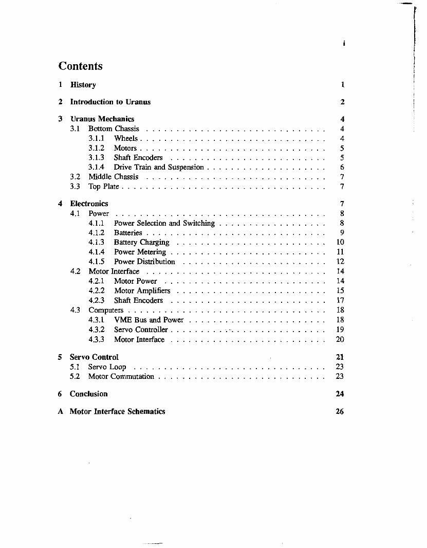
Contents 1 History 1
2 Introduction to Uranus 2
3 Uranus Mechanics 4 3.1 Bottomchassis . . . . . . . . . . . . . . . . . . . . . . . . . . . . . . 4
3.1.1 Wheels . . . . . . . . . . . . . . . . . . . . . . . . . . . . . . . 4 3.1.2 Motors . . . . . . . . . . . . . . . . . . . . . . . . . . . . . . . 5 3.1.3 ShaftEncoders . . . . . . . . . . . . . . . . . . . . . . . . . . 5 3.1.4 Drive Train and Suspension . . . . . . . . . . . . . . . . . . . . 6
3.2 Middlechassis . . . . . . . . . . . . . . . . . . . . . . . . . . . . . . 7 3.3 TopPlate . . . . . . . . . . . . . . . . . . . . . . . . . . . . . . . . . . 7
4 Electronics 7 4.1 Power . . . . . . . . . . . . . . . . . . . . . . . . . . . . . . . . . . . 8
4.1.1 Power Selection and Switching . . . . . . . . . . . . . . . . . . 8 4.1.2 Batteries . . . . . . . . . . . . . . . . . . . . . . . . . . . . . . 9 4.1.3 BaneryCharging . . . . . . . . . . . . . . . . . . . . . . . . . 10 4.1.4 Power Metering . . . . . . . . . . . . . . . . . . . . . . . . . . 11 4.1.5 Power Distribution . . . . . . . . . . . . . . . . . . . . . . . . 12
4.2 Motor Interface . . . . . . . . . . . . . . . . . . . . . . . . . . . . . . 14 4.2.1 Motor Power . . . . . . . . . . . . . . . . . . . . . . . . . . . 14 4.2.2 MotorAmplifim . . . . . . . . . . . . . . . . . . . . . . . . . 15 4.2.3 Shaft Encoders . . . . . . . . . . . . . . . . . . . . . . . . . . 17
4.3 Computers . . . . . . . . . . . . . . . . . . . . . . . . . . . . . . . . . 18 4.3.1 VMEBusandPower . . . . . . . . . . . . . . . . . . . . . . . 18 4.3.2 Servo Controller . . . . . . . . . . . . . . . . . . . . . . . . . . . . 19 4.3.3 MotorInterface . . . . . . . . . . . . . . . . . . . . . . . . . . 20
5 Servo Control 21 5.1 ServoLoop . . . . . . . . . . . . . . . . . . . . . . . . . . . . . . . . 23 5.2 Motor Commutation . . . . . . . . . . . . . . . . . . . . . . . . . . . . 23
6 Conclusion 24
A Motor Interface Schematics 26
..
iii
List of Figures 1 2 3 4 5 6 7 8 9 10 11 12 13 14 15 16 17
Neptune and Pluto . . . . . . . . . . . . . . . . . . . . . . . . . . . . . 2 Uranus . . . . . . . . . . . . . . . . . . . . . . . . . . . . . . . . . . . 3 Mechanum wheels . . . . . . . . . . . . . . . . . . . . . . . . . . . . . 4 Drivetrain . . . . . . . . . . . . . . . . . . . . . . . . . . . . . . . . . 6 Topplate . . . . . . . . . . . . . - . . . . . . . . . . . . . . . . . . . . 7 Power system overview . . . . . . . . . . . . . . . . . . . . . . . . . . 8 Power selection and switching . . . . . . . . . . . . . . . . . . . . . . 9 Batterypack . . . . . . . . . . . . . . . . . . . . . . . . . . . . . . . . 10 Chargingcircuitry . . . . . . . . . . . . . . . . . . . . . . . . . . . . . 11 Powermeters . . . . . . . . . . . . . . . . . . . . . . . . . . . . . . . 12 Power distribution . . . . . . . . . . . . . . . . . . . . . . . . . . . . . 13 Motor power . . . . . . . . . . . . . . . . . . . . . . . . . . . . . . . . 14 Motor amplifier wiring . . . . . . . . . . . . . . . . . . . . . . . . . . 16 Motor amplifier . . . . . . . . . . . . . . . . . . . . . . . . . . . . . . 17 Motor amplifier placement . . . . . . . . . . . . . . . . . . . . . . . . 18 Simple servo loop pseudo-code . . . . . . . . . . . . . . . . . . . . . . 22 Commutation pseudo-code . . . . . . . . . . . . . . . . . . . . . . . . 22
.
V
Abstract
The Uranus mobile robot was built by Camegie Mellon University’s Mobile Robot Lab to provide a general purpose mobile base to suppon research in to indoor robot navigation. As a base, it provides full mobility, along with support for a variety of payloads, such as sensors and computers. This report details the design and maintenance of Uranus’s mechanical, electrical, and software systems, and is intended to serve two purposes. First, it acts as documentation for the robot. Second, it offers a perspective in to mobile robot design, showing the decisions, tradeoffs, and evolution that are involved in the design of a system of this complexity. Hopefully, others building similar systems will be able to profit from OUT experience.
1
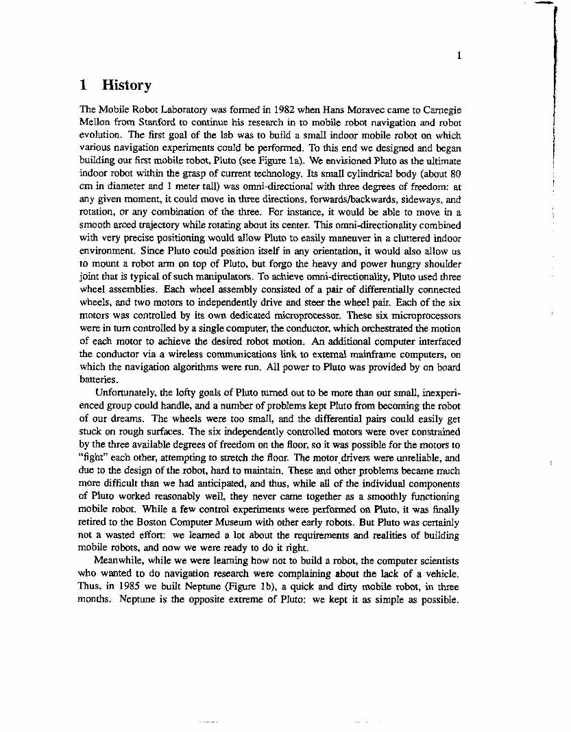
1 History The Mobile Robot Laboratory was formed in 1982 when Hans Moravec came to Camegie Mellon from Stanford to continue his research in to mobile robot navigation and robot evolution. The first goal of the lab was to build a small indoor mobile robot on which various navigation experiments could be performed. To this end we designed and began building ow first mobile robot, Pluto (see Figure la). We envisioned Pluto as the ultimate indoor robot d i n the grasp of current technology. Its s m a l l cylindrical body (about 80 cm in diameter and 1 meter tall) was omnidirectional with three degrees of freedom: at any given moment, it could move in three directions, forwardsbackwards, sideways, and rotation, or any combination of the three. For instance, it would be able to move in a smooth arced trajectory while rotaring about its center. This omni-directionality combined with very precise positioning would allow Pluto to easily maneuver in a cluttered indoor environment. Since Pluto could position itself in any orientation, it would also allow us to mount a robot arm on top of Pluto, but forgo the heavy and power hungry shoulder joint that is typical of such manipulators. To achieve omni-dkctionality, Pluto used three wheel assemblies. Each wheel assembly consisted of a pair of differentially connected wheels, and two motors to independently drive and steer the wheel pair. Each of the six motors was controlled by its own dedicated microprocessor. These six microprocessors were in turn coneofled by a single computer, the conductor, which orchestrated the motion of each motor to achieve the desired robot motion. An additional computer interfaced the conductor via a wireless communications link to external mainframe computers, on which the navigation algorithms were run. All power to Pluto was provided by on board batteries.
Unfortunately, the lofty goals of Pluto turned out to be more than OUI small, inexperi- enced group could handle, and a numb= of problems kept Pluto from becoming the robot of our dreams. The wheels were too small, and the differential pairs could easily get stuck on rough surfaces. The six independently controlled motors were over constrained by the three available degrees of freedom on the floor, so it was possible for the motors to “fight” each other, attempting to smtch the floor. The motor drivers were unreliable, and due to the design of the robot, hard to maintain. These and other problems became much more difficult than we had anticipated, and thus, while all of the individual components of Pluto worked reasonably well they never came together as a smoothly functioning mobile robot. While a few control experiments were performed on Pluto, it was finally retired to the Boston Computer Museum with other early robots. But Pluto was certainly not a wasted effort: we learned a lot about the requirements and realities of building mobile robots, and now we were ready to do it right.
Meanwhile, while we were learning how not to build a robot, the computer scientists who wanted to do navigation research were complaining about the lack of a vehicle. Thus, in 1985 we built Neptune (Figure Ib), a quick and dirty mobile robot, in three months. Neptune is the opposite extreme of Pluto: we kept it as simple as possible.
2
Figure 1: Early mobile robots: (a) Pluto with single camera on slider. (b) Neptune with ring of sonar s e n s a .
Basically a remote controlled platform for carrying various senson, Neptune is a three wheeled mcycle with two motm: one for driving and one for steering. The motors are synchronous AC motors which run at a fixed speed: they are either on or off. The only position feedback from the motors is a micro switch indicating if the steering wheel is centered. Power and communications are via an umbilical cable. There is only a single computer on board, which takes high level motion commands via a serial port and attempts to execute them by turning the motors on and off for appropriate time intervals. Despite all of its limitations, Neptune still works reliably, and has been used for a wide variety of navigation research.
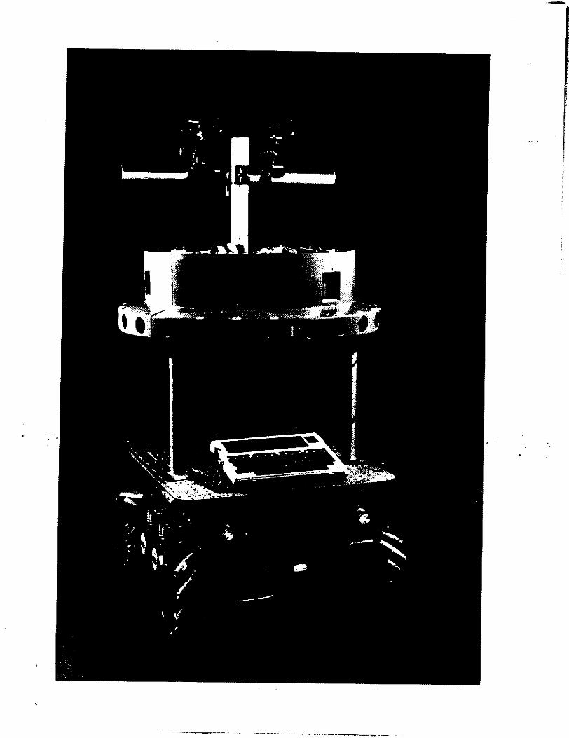
2 Introduction to Uranus With Neptune completed, we again looked at our original objective: a small, powerful mobile robot capable of autonomous indoor navigation. In 1986, we began conshucdon of ow third mobile robot, Uranus' (Figure 2). Like Pluto, Uranus is battery powered and can move precisely with three degrees of freedom on the floor. Unlike Pluto, Uranus works quite well.
Uranus is about 60 ern wide, 75 cm long, and 40 cm tall (Without sensors), and weighs about 50 kg. Its most unique and sniking feature is its wheels, which give the robot its three degrees of freedom. Thee wheels were designed by the Mecanum company of Sweden for use in wheel chairs, and perform ideally for a robot of this size. The circumference of each wheel is lined with rollers set at 45 degrees relative to the main wheel axis (see Figure 3). For a pair of wheels, the rollers on each wheel are set in
'To avoid endless bad puns, we pronounce i t UR-ah-nus.
3
Figure 2: Uranus.
opposite directions. When both wheels of a pair are driven in same direction, motion in the rollers is cancelled, so the pair will move forwards or backwards just like an ordinary pair of wheels. However, when the wheels are driven in opposite directions, the rollers will act like a screw, and the pair will move sideways. With four of these wheels, Uranus can move in the three possible directions on the floor simultaneously. Note that this is still an over constrained system (four motors for three degrees of freedom), but it is an easier control problem than Pluto, and minor position errors in an individual motor will simply cause a small amount of wheel slip.
Each wheel is independently shock mounted, and is driven by a powerful DC brushless motor. A drive train of gem and link belts connect the motor to the wheel. A shaft encoder is coupled directly to the motor shaft to provide position feedback to the motor conaoller. The motor driver amplifiers are built directly into the motor housing to provide adequate heat sinking.
Mounted on the same level as the wheels and motors, two sealed lead acid baneries and the associated switching and charging circuitry, provide all on board power. Mounted on the level above this is power distribution, and the computer card cages. These consist of two 5-slot VME bus cages, with DC-DC switching power supplies providing the appropriate voltages. Three of the 10 bus slots are used by the motor servo controller, the rest are free for navigational computing.
The top of Uranus is covered by a thick aluminum plate gridded by threaded holes, allowing any type of sensor or other experiment specific equipment to be easily mounted.
4
Figure 3: a. A Mecanum wheel. b. Wheel configuration on Uranus.
3 Uranus Mechanics Uranus is consmcted entirely of anodized aluminum. The robot can be vertically divided, both conceptually and physically, in to three distinct sections. The bottommost section contains the wheels, motors, and batteries, along bulk power switching and charging functions. The middle section of the robot contains power conditioning and distribution, and the on board computers. These two sections are capped by the top plate, on to which experiment specific equipment can be attached.
3.1 Bottom Chassis
The bottom section is built from four 3 inch by 6 inch rectangular aluminum tubes with 3/16 inch thick walls. The motors and wheel suspension are mounted to the two side tubes, with the drive train running inside. One end tube houses the battery charging circuitry, while the other houses the shore power connector and switches for main power and battery/off board power selection. A battery pan mounts in the cavity formed by the four tubes, holding the two batteries. Each of the side tubes can be removed intact with minimal disassembly, to aid in motor and drive train maintenance.
3.1.1 Wheels
Uranus is built around four Mecanum wheels (Figure 3a), as described earlier. These wheels are about 9 inches in diameter, and axanged such that their points of contact with the floor form a perfect square, as shown in Figure 3b. The square configuration is not necessary for three degree of freedom motion, but it does make the control equations simpler.
In this configuration, the equation relating the overall vehicle velocity in the X, Y, and 9 directions given wheel velocities of VO, VI, V,, and V, is:
vx = ( V o + ~ + v Z + v 3 ) / 4 (1)
5
Note that since there are four controllable velocities, there is a fourth independent velocity term, V,,, which corresponds to stretch in the floor:
This term is always servoed to zero to prevent wheel slippage.
3.1.2 Motors
Uranus is propelled by four Inland Motor BM-3201 brushless DC synchronous motors. The rotor has an &pole permanent magnetic field, using rare earth samarium-cobolt permanent magnets. Coil windings in the stator form three phases, and are internally connected in a three-leg delta configuration. Each motor weighs 4 pounds (excluding housing), and can produce 650 ounce inches peak torque. We used these particular motors because of their small size and high power density, and also because they were expensive and we had them left over from Pluto. Their primary disadvantage is that there are no commercial controllers available, so we had to design OUT own.
Each motor housing is machined aluminum, anodized black, with built in heat sink fins (a stalled motor can draw 212 watts). The motor driver amplifiers are built inside the housing, with the transistor heat tabs bolted directly to the housing case. A recessed area in the housing accommodates the shaft encoder, allowing it to attach directly to the motor shaft. Two connectors mount to the top of the housing, one for motor driver power, and the other for digital control and shaft encoder signals.
3.13 Shaft Encoders
Each motor has a shaft encoder attached directly to its rotor. This shaft encoder provides position feedback for the motor servo controller. The shaft encoders are BE1 Electronics Type E25 1024-count incremental optical encoders. The LED illumination source option was chosen for ruggedness and long life. The internal circuitry of the encoders is CMOS for low power consumption (125 mA typical). The outputs are dual quadramre, with index, which can be decoded by the interface circuitry into an absolute position with a resolution of 4096 counts per motor revolution.
On the Pluto robot we had used more inexpensive two p i e encoder assemblies. We experienced numerous problems with drifting alignment and disk breakage, due to lower tolerances in the motor design. These BEI shaft encoders are self contained, sealed units, and are attached to the motor roton via compliant helical couplings, eliminating all of these problems.
6
1
Wheel
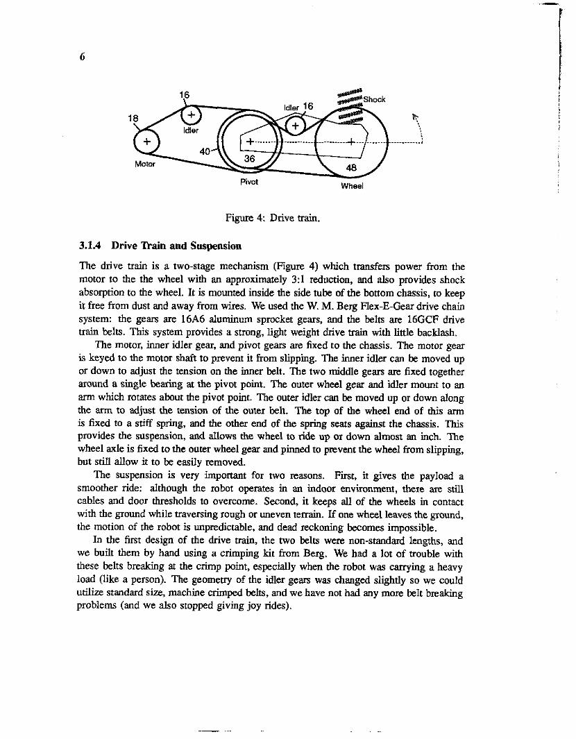
Figure 4: Drive train,
3.1.4 Drive lkain and Suspension
The drive train is a two-stage mechanism (Figure 4) which transfers power from the motor to the the wheel with an approximately 3:l reduction, and also provides shock absorption to the wheel. It is mounted inside the side tube of the bottom chassis, to keep it free from dust and away from wires. We used the W. M. Berg Flex-E-Gear drive chain system: the gears are 16A6 aluminum sprocket gears, and the belts are 16GCF drive train belts. This system provides a strong, light weight drive train with little backlash.
The motor, inner idler gear, and pivot gears are fixed to the chassis. The motor gear is keyed to the motor shaft to prevent it from slipping. The inner idler can be moved up or down to adjust the tension on the inner belt. The two d d d l e gears are fixed together around a single bearing at the pivot point. The outer wheel gear and idler mount to an arm which rotates about the pivot point. The outer idler can be moved up or down along the arm to adjust the tension of the outer belt. The top of the wheel end of this arm is fixed to a stiff spring, and the other end of the spring seats against the chassis. This provides the suspension, and allows the wheel to ride up or down almost an inch. The wheel axle is fixed to the outer wheel gear and pinned to prevent the wheel from slipping, but still allow it to be easily removed.
The suspension is very important for two reasons. First, it gives the payload a smoother ride: although the robot operates in an indoor environment, there are still cables and door thresholds to overcome. Second, it keeps all of the wheels in contact with the ground while traversing rough or uneven terrain. If one wheel leaves the ground, the motion of the robot is unpredictable, and dead reckoning becomes impossible.
In the first design of the drive train, the two belts were non-standad lengths, and we built them by hand using a crimping kit from Berg. We had a lot of !rouble with these belts breaking at the crimp point, especially when the robot was carrying a heavy load (like a person). The geometry of the idler gears was changed slightly so we could utilize standard size, machine crimped belts, and we have not had any more belt bEaking problems (and we also stopped giving joy rides).
7
* * * . . * .* . . . +. .+ I . . * * + . . + . * * * * I * * . . * * . . * * *
. I . * . * * . _ . I . . .o* . * _ . * . I
* * * . t * I _ * * * * . . * * + . * . * . * * * * .
T 5-
Jl * I . * * . * . f...*.~t..,~.l**.** *......**.+.*o.....-***.... * * * * * * * ( I r * . r ~ ~ * . - * . t .
. * . * . . * . * * * * * . * . * * * . * . . * *
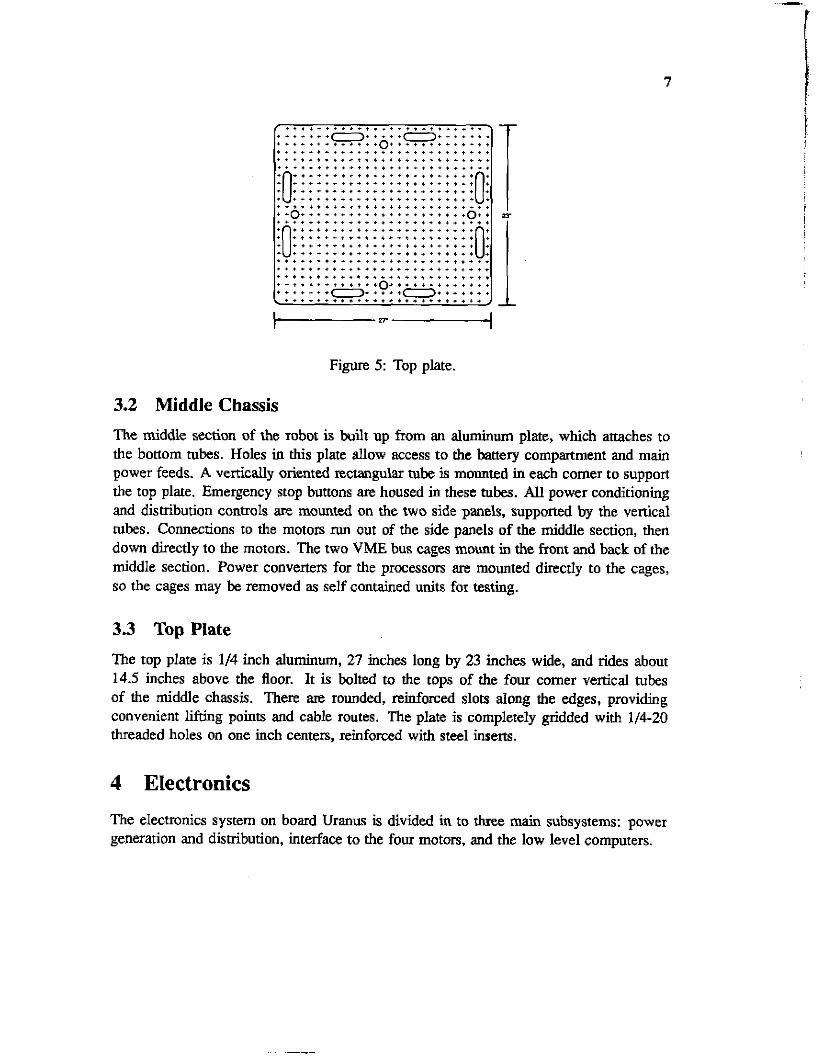
Figure 5: Top plate.
3.2 Middle Chassis
The middle section of the robot is built up from an aluminum plate, which attaches to the bottom tubes. Holes in this plate allow access to the banery compartment and main power feeds. A vertically oriented rectangular tube is mounted in each comer to support the top plate. Emergency stop buttons are housed in these tubes. All power conditioning and dismhution controls are mounted on the two side panels, supported by the vertical tubes. Connections to the motors run out of the side panels of the middle section, then down directly to the motors. The two VME bus cages mount in the front and back of the middle section. Power converters for the processors are mounted directly to the cages, so the cages may be removed as self contained units for testing.
3.3 Top Plate The top plate is 1/4 inch aluminum, 27 inches long by 23 inches wide, and rides about 14.5 inches above the floor. It is bolted to the tops of the four comer vertical tubes of the middle chassis. There are rounded, reinforced slots along the edges, providing convenient lifdng points and cable routes. The plate is completely gridded with 1/4-20 threaded holes on one inch centers, reinforced with steel inserts.
4 Electronics The electronics system on board Uranus is divided in to three main subsystems: power generation and distribution, interface to the four motors, and the low level computers.
Power S e l e c t i o n 24v Inlet
- . B a t t e r ,
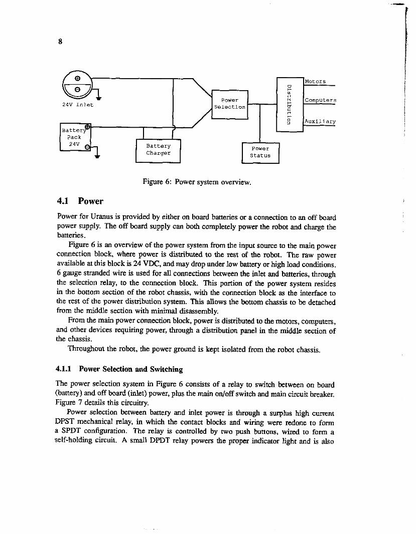
Figure 6: Power system overview.
4.1 Power Power for Uranus is provided by either on board batteries or a connection to an off board power supply. The off board supply can both completely power the robot and charge the batteries.
Figure 6 is an overview of the power system from the input source to the main power connection block where power is distributed to the rest of the robot. The raw power available at this block is 24 VDC, and may drop under low battery or high load conditions. 6 gauge stranded wire is used for all connections between the inlet and batteries, through the selection relay, to the connection block. This portion of the power system resides in the bottom section of the robot chassis, with the connection block as the interface to the rest of the power distribution system. This allows the bottom chassis to be detached from the middle section with minimal disassembly.
From the main power connection block, power is distributed to the motors, computers, and other devices requiring power, through a distribution panel in the middle section of the chassis.
Throughout the robot, the power ground is kept isolated from the robot chassis.
Motors 0 +. m 0
u c: rl k-
c o m p u t e r s
A u x i l i a r y
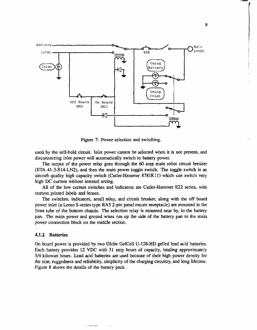
4.1.1 Power Selection and Switching
The power selection system in Figure 6 consists of a relay to switch between on board (battery) and off board (inlet) power, plus the main on/off switch and main circuit breaker. Figure 7 details this circuitry.
Power selection between battery and inlet power is through a surplus high current DPST mechanical relay, in which the contact blocks and wiring were redone to form a SPDT configuration. The relay is controlled by two push buttons, wired to form a self-holding circuit. A small DPDT relay powers the proper indicator light and i s also
24v e r
Power S t a t u s
B a t t e r y C h a r g e r
9
Main B a t t e r y
I n l e t
I n l e t
Figure 7 Power selection and switching.
used by the self-hold circuit. Inlet power cannot be selected when it is not present, and disconnecting inlet power will automaridly switch to bamry power.
The output of the power relay goes through the 60 amp main robot circuit breaker (ETA 41-3-S14LN2), and then the main pow= toggle switch. The toggle switch is an aircraft qualify high capacity switch (Cutler-Hammer 8781Kll) which can switch very high DC current without internal axing.
All of the low current switches and indicators are Cutler-Hammer E22 series, with custom printed labels and lenses.
The switches, indicators, small relay, and circuit breaker, along with the off board power inlet (a Lemo S-series type FA5 2-pin panel mount receptade) are mounted in the front tube of the bottom chassis. The selection relay is mounted near by, in the battery pan. The main power and ground wires run up the side of the battery pan to the main power connection block on the middle section.
4.1.2 Batteries
On board power is provided by two Globe GelCell U-128-HD gelled lead acid batteries. Each battery provides 12 VDC with 31 amp hours of capacity, totaling approximately 3/4 kilowatt hours. Lead acid batteries are used because of their high power density for the size, ruggedness and reliability, simplicity of the charging circuitry, and long lifetime. Figure 8 shows the details of the battery pack.
10
Figure 8: 24 volt DC battery pack.
A 60 amp DC circuit breaker (ETA 41-3-SI4-LN2) is positioned close to the battery terminals, to help prevent damage in case of an accidental short of the main battery wires.
The batteries are mounted on thek sides mount in the battery pan, secured by a plastic bracket. The terminals face inwards to keep connections lengths short and protect the exposed portions.
4.13 Battery Charging
The first battery charge on board Uranus was a JX-DC convener driven from the 24 VDC off board inlet. This converter produced a constant 28.8 volts, which was fed to the bmeries through a ament limiting resistor. This chatger worked, but had the unfortunate property that if you forgot to turn it off, it would over-charge the batteries and eventually destroy them by boiling off the electrolytic (which can’t be replaced in a gelled type battery). This led to the design of a new charger which could be reliably left hooked to the batteries, switching between “charge” and “maintenance” modes automafically. Tne new charger is also powered from wall power, to keep the thickness of the power cord down.
The new battery charger (Figure 9) is mounted in the ‘‘rear” tube of the up the bottom section of Uranus. Input is a standard DIN style AC receptacle, with a built in on-off switch and fuse. The charger can supply a maximum of five amps to the batteries, allowing a total recharge time of about six hours.
The charger consists of two parts; the charging circuit and the power supply. Due to size constraints (space in the tube limits the size to about 3” x 3” x 7”) a traditional transformer based linear power source could not be used. Instead, a high efficiency DC- JX converter is used. A standard DIN style power cord brings 120 VAC to the 250 Volt 12 amp full wave bridge rectifier with a 47pF 150 volt electrolytic capacitor in shunt with DC side of the bridge to reduce ripple. Thii is fed to the DC to DC converter (Vicor VI-L%CU) which converts the 165 VDC to the -28.8 VJX needed by the charger circuit. Normally the converter puts out 48 VDC, but this is adjusted by setting the 20Kn potentiometer P1 to approximately 11.6161.
Charging is controlled by a circuit built around the Unitrode UC3906 charger IC. This chip implements a three stage charging sequence. When the batteries are significantly
11
Figure 9: Charging circuitry.
discharged, the charger goes into bulk charge mode, dumping the maximum current (I-), five amps, to the batteries. As the batteries come up to the overcharge voltage (V,) of 28.8 volts, the charger enters overcharge mode, which maintains the batteries at V , until the current drops below the overcharge terminate current &) of 0.5 amps. At I,,, the charger goes into float mode which it wil l maintain until one of the other two modes is triggered. In float mode, the charger holds the batteries at the float voltage (Vr) of 27.6 volts. LEDs on the front panel of the charger indicate when the charger is on, and when it is in overcharge mode. The pertinent equations for selecting the proper resistances are:
V , = 2.3(1+ R n / R s + RA/Rc) V f = 2 . 3 ( 1 + R a / R ~ )
1- = .25V/Rs Ion = .025V/Rs
4.1.4 Power Metering
The power metering circuirry (Figure 10) displays the voltage and power consumption of the robot on two analog meters. The meters are mounted on the side of one of the vertical comer tubes in the middle chassis, and the power supply, amplifier, and connectors are built on a perf board mounted to the same. tube. A switch turns the whole meter section on and off, so no power is used when the meters are not needed.
12
30 VLJC Main F. W.Bell
f r o m power
+15. meter
30 VLJC Main F. W.Bell
f r o m power
Amps x10
-15.meter
Figure 10: Power meters.
The voltage is measured with a simple 30 volt DC meter (Triplett 2204). Current is measured with an E W. Bell MA-100 Hall effect current sensor. This sensor produces a voltage which is proportional to the current flowing through its sense coil. The sensor is mounted in the banery pan near the power selection relay, and the main power feed wire from the relay to the power connection block is routed through the sensor. The sensor output is amplified by a simple op amp circuit which feeds a 5 volt DC meter (also a Triplen 220-G). The amplifier gain can be adjusted so the scale of the meter (0 to 5 volts) corresponds to a 0 to 50 amp current range. A Pic0 LRA15D DC/DC converter provides +15 and -15 volts to the Hall effect sensor and the op amp.
4.1.5 Power Distribution
A switch panel on the left side of the middle chassis controls power distribution from the main power connection block to thre main branches: computers, motors, and a u x i l i i (Figure 11). The configuration of each section is identical. A pair of momentary contact buttons controls a Crydom DlD20 solid state relay wired in a self-holding fashion: the normally open bunon will turn the relay on, and the normally closed button will break the connection. The relays are rated for 20 amps DC, and switch the main 24 volts DC from the power connection block through an ETA 45-700-P10-DD 10 amp DC circuit breaker. Each switchhelay section has a labeled light which indicates when the relay is
13
Main 24v
MOTOR STOP
Snitches
Figure 11: Power distribution.
energized. The buttons and indicators are Cutler-Hammer E22 series with custom printed labels.
The power down button on the motor branch is wired in series with four other normally closed buttons. These are the four large red, lighted, motor stop buttons - one on each of the vemcal middle chassis tubes. The buttons are lit when the motors have power, and pressing any one of them will power down the motors, but leave the rest of the robot running. The motor stop buttons are Cutler-Hammer A161 series with 24VDC lamps and DC rated normally closed switch contact blocks.
The motor power branch from the distribution panel does not actually power the
14
Main 24V
-3 Motor Enable
xT7-l t24
Motor Power Connection
1: Gnd (BLK) 2: 0+12 (BRN) 3: 24-12 (ORG) 4: +24 (RED)
24-12 7912
E 0 rt 0 e
Gnd
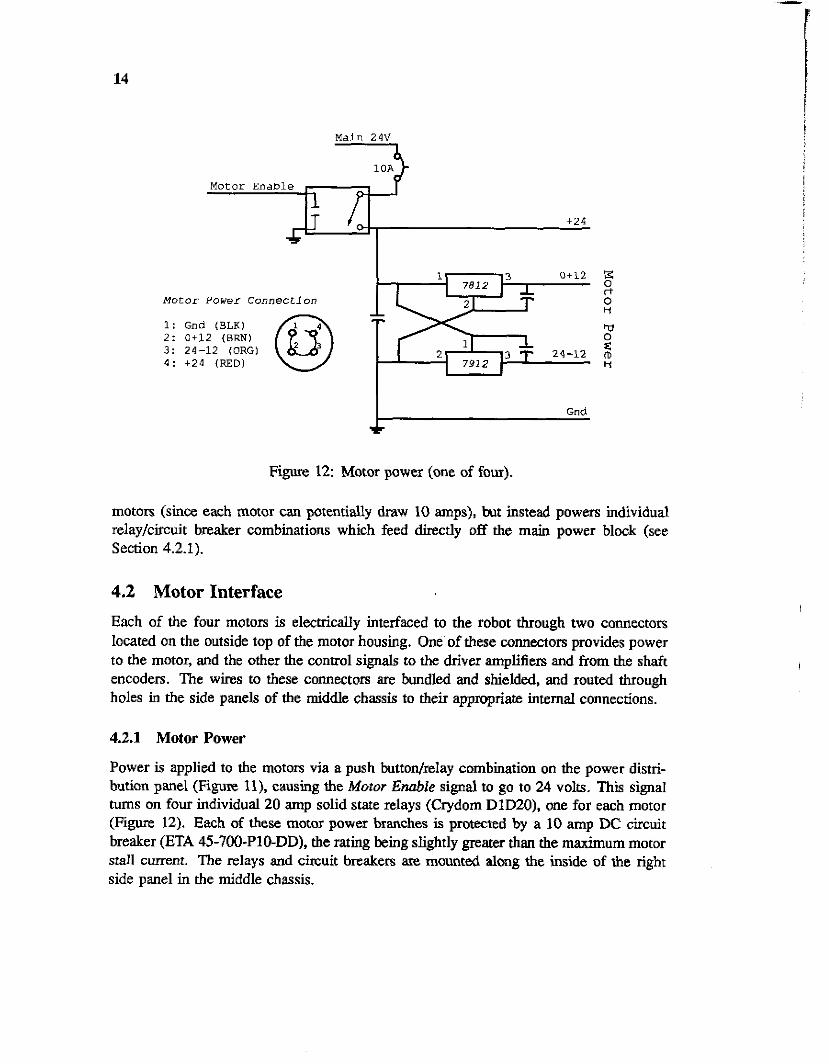
Figure 1 2 Motor power (one of four).
motors (since each motor can potentially draw 10 amps), but instead powers individual relay/circuit breaker combinations which feed directly off the main power block (see Section 4.2.1).
4.2 Motor Interface Each of the four motors is electrically interfaced to the robot through two connectors located on the outside top of the motor housing. One of these connectors provides power to the motor, and the other the control signals to the driver amplifiers and from the shaft encoders. The wires to these COMeCtOrS are bundled and shielded, and routed through holes in the side panels of the middle chassis to their appmpriate internal connections.
4.2.1 Motor Power
Power is applied to the motors via a push button/relay combination on the power distri- bution panel (Figure II), causing the Motor Enable signal to go to 24 volts. This signal turns on four individual 20 amp solid state d a y s (Crydom DID20). one for each motor (Figure 12). Each of these motor power branches is protected by a 10 amp DC circuit breaker (ETA 45-700-P10-DD), the rating being slightly greater than the maximum motor stall c m n t . The relays and circuit breakers are mounted almg the inside of the right side panel in the middle chassis.
15
The relays switch raw 24 volts from the batteries to the motor amplifiers, since no regulation is necessary, but high current is. Along with the 24 volts, two regula&, low current voltages are also supplied to the amplifiers: One is 12 volts above the ground rail (0+12), and the other 12 volts below the positive rail (24-12). Nominally, these signals will both be at 12 volts, but as the battery voltage drops due to discharge and load, the 24-12 volt signal will also drop, maintaining a 12 volt differential. It is this differential that is necessary for the amplifiers, not the absolute voltage level.
The 0+12 and 24-12 references are generated by standard 7812 and 7912 linear regulators, with lpF bypass capacitors. The regulators are in TO-220 packages, and the whole regulator assembly (one for each motor) is mounted on a shelf below the motor relays and breakers.
The power connection to the motor is through a Lemo B-series type FHG 4-pin right angle plug, wired as shown in Figure 12. Ground and +24 volts are provided through 14 gauge teflon coated wire, and the 0+12 and 24-12 references are through 24 gauge hookup wire. The four wires are bundled in a braided shield to help reduce amplifier switching noise. On the motor, a matching Lemo type EGG panel mount receptacle terminates the connection and brings the signals through the motor housing to the amplifiers. The Lemo connectors were chosen for their size, reliability, and positive locking fearures.
4.2.2 Motor Amplifiers
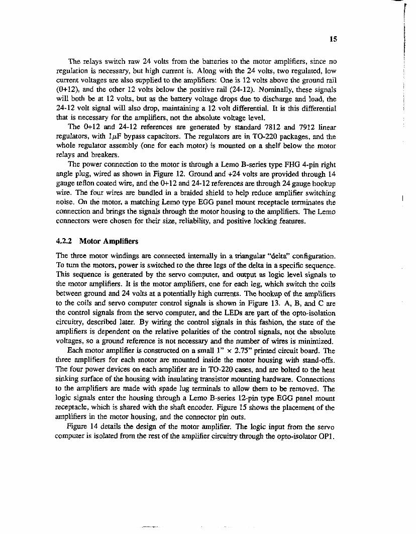
The three motor windings are. connected internally in a triangular “delta” configuration. To turn the motors, power is switched to the three legs of the delta in a specific sequence. This sequence is generated by the servo computer, and output as logic level signals to the motor amplifiers. It is the motor amplifiers, one for each leg, which switch the coils between ground and 24 volts at a potentially high currents. The hookup of rhe amplifiers to the coils and servo computer control signals is shown in Figure 13. A, B, and C are the control signals from the servo computer, and the LEDs are part of the opto-isolation circuitry, described later. By wiring the control s i ~ a l s in this fashion, the stare of the amplifiers is dependent on the relative polarities of the control signals, not the absolute voltages, so a ground reference is not necessary and the number of wires is minimized.
Each motor amplifier is constructed on a small 1” x 2.75” printed circuit board. The three amplifiers for each motor are mounted inside the motor housing with stand-offs. The four power devices on each amplifier are in TO-220 cases, and are bolted to the heat sinking surface of the housing with insulating transistor mounting hardware. Connections to the amplifiers are made with spade lug terminals to allow them to be removed. The logic signals enter the housing through a Lemo B-series lZpin type EGG panel mount receptacle, which is shared with the shaft encoder. Figure 15 shows the placement of the amplifiers in the motor housing, and the connector pin outs.
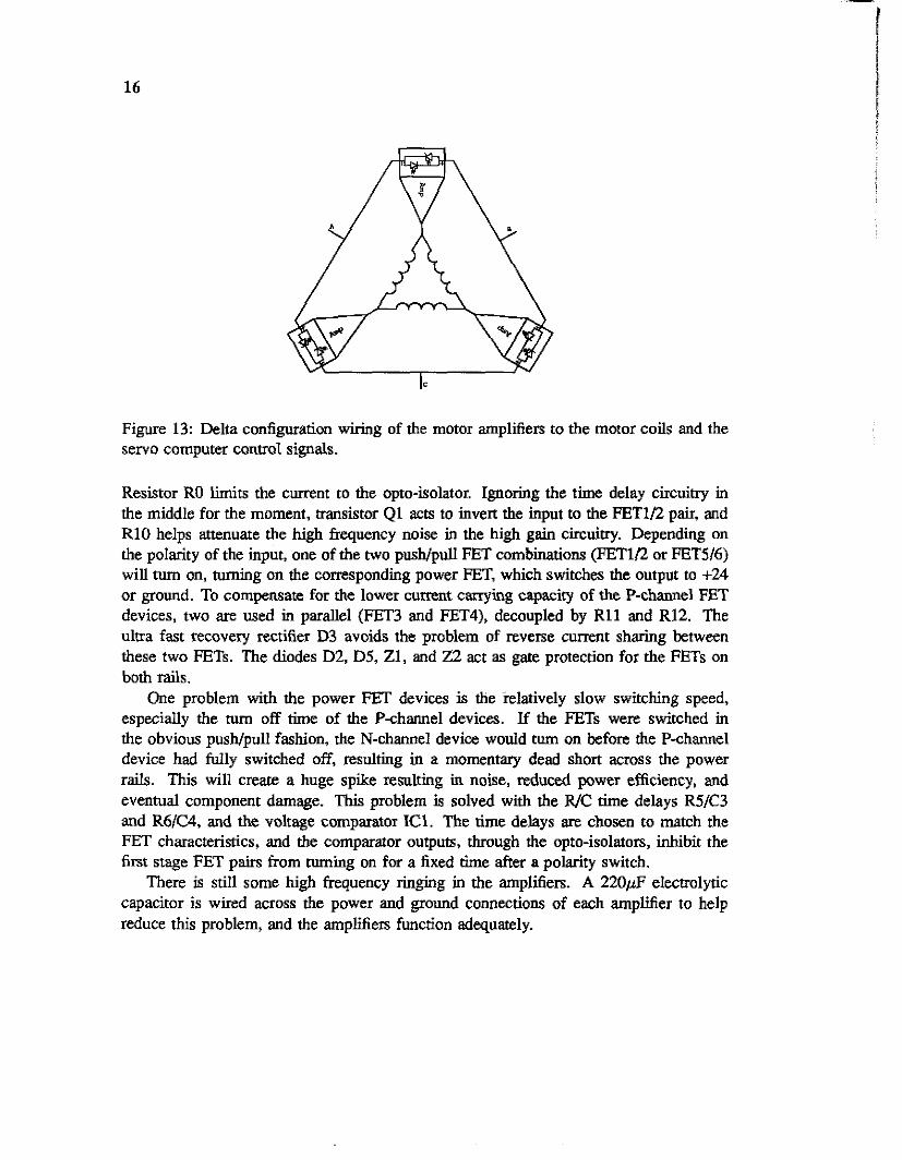
Figure 14 details the design of the motor amplifier. The logic input from the servo computer is isolated from the rest of the amplifier circuitry through the opto-isolator OPI.
16
Figure 13: Delta configuration wiring of the motor amplifiers to the motor coils and the servo computer control signals.
Resistor RO limits the current to the opto-isolator. Ignoring the time delay circuitry in the middle for the moment, transistor Q1 acts to invert the input to the FETID pair, and R10 helps attenuate the high frequency noise in the high gain circuitry. Depending on the polarity of the input, one of the two push/pull FET combinations (FETln or FET5/6) will turn on, turning on the corresponding power ET , which switches the output to +24 or ground. To compensate for the lower current carrying capacity of the P-channel FET devices, two are used in parallel (FET3 and FET4), decoupled by R11 and R12. The ultra fast recovery rectifier D3 avoids the problem of reverse current sharing between these two FETs. The diodes D2, D5, Z1, and 22 act as gate protection for the FETs on both rails.
One problem with the power FET devices is the relatively slow switching speed, especially the turn off time of the Pchannel devices. If the FETs were switched in the obvious pusWpull fashion, the N-channel device would turn on before the P-channel device had fully switched off, resulting jn a momentary dead short across the power rails. This will creare a huge spike resulting in noise, reduced power efficiency, and eventual component damage. This problem is solved with the R/C time delays R5/C3 and R K 4 , and the voltage comparator IC1. The time delays are chosen to match the FET characteristics, and the comparator outputs, through the opto-isolators, inhiba the first stage FET pairs from turning on for a fixed time after a polarity switch.
There is still some high frequency ringing in the amplifiers. A 220pF electrolytic capacitor is wired across the power and ground connections of each amplifier to help reduce this problem, and the amplifiers function adequately.
17
Figure 14 Motor amplifier (one of three per motor).
4.23 Shaft Encoders
Each shaft encoder couples directly to the back of the motor shaft, and is mounted inside of the motor housing. Five wires electrically interface the shaft encoder to the servo computer: ground and power, the two quadrature signals, and the index signal. These signals exit the motor housing through the receptacle &and with the amplifier control signals, and are connected as shown in Figure 15. Inside the motor housing, the shaft encoder wires are coupled to the receptacle with a flat 5-pin Moleflaldom WM-72 miniature connector, to allow the shaft encoder to be easily removed.
One problem with the shaft encoders is that they provide a relative position output, plus an index pulse once per revolution. This index pulse is used to synchronize the shaft encoder interfae, to maintain an absolute position, which is required to properly commutate the motors. Thus, whenever power is applied to the shaft encoders, they must be spun one full revolution to synchronize the interface. This is usually performed immediately after the robot is powered up by giving it a small shove.
Power to the shaft encoders must be regulated +5 volts. Instead of regulating this from the motor power branch, this power is supplied by the servo computer over the signal connector. This was done for two reasons: it was more convenient and did not
18
f (244-;2)
~ 4 )
, Encoder Red (21 . . Green B Yellow
Encoaer Black (1)
Enmder Ydbw (51
Figure 15: Placement of amplifiers in motor housing, and connector pin outs.
require an additional voltage regulator, but more imponantly it allows the shaft encoders to remain powered even when the motors are shut off. The motors are often shut off to prevent the robot from accidently colliding with an obstacle, and if the shaft encoders got power from this source, they would need to be reinitialized each time. The computer is generally turned on once when the robot is powered up. and left turned on.
4.3 Computers Uranus was designed to cany and support substantial computing power on board. The computing performs two basic tasks: low level motion control and robot maintenance (servoing the motors, monitoring robot status, communications), and high level navigation and sensor/payload specific actions. The computing support resources are physically divided in two, reflecting the separation of these tasks.
4.3.1 VME Bus and Power
Uranus houses two 5-slot 6U VME bus card cages, occupying most of the space in the middle section of the robot. The front panels of the installed cards face outwards to
f I
19
the front and back, with the back planes in the middle. n e card cages were assembled from modular components made by Schroff. The VME bus was chosen for the wide variety of products available. The back planes are configured in the standard dual wide fashion, with the P1 and row B of the P2 connectors bussed through, and P2 rows A anc C left open. If necessary, the card cage can be reconfigured to hold 10 single wide (3U) cards. Two small fans on each cage force air through the cage across the boards, and are turned on when computer power is applied. Although the fans are quiet, they are still the noisiest component of the robot during operation. Thermostatically connolled fans were. considered, but never implemented.
Power to the back planes is supplied by DC/DC converters mounted on an aluminum bracket between the NO back planes. With minor disassembly, the bracket can swing out of the way to allow access to the F'2 COM&OIS. 24 volt raw power to the converters comes from the computer branch of the power distribution panel, through a high current diode which keeps back current (from the still spinning fans) from holding the distribution relay closed when the power down button is pressed. A Vicor VI-110 DC/DC converter provides +5 volts at 15 amps, and two Micro Power 12 volt converters supply plus and minus 12 volts at 1 amp each. Note that the +S volt supply is also routed to the motor shaft encoders (Section 4.2.3).
43.2 Servo Controller
The workhorse computer on board Uranus is the servo controller, whose sole function is to accept high level motion commands (either from another computer or a joystick), and properly servo and commutate the four motors to achieve those motions. This computer and its associated interface hardware occupy most of one of the VME bus card cages.
The first controller computer used on Uranus was a Force CPU-lB, based on a 8MHz Motorola 68000 microprocessor. It supported 128K bytes of RAM, 128K bytes of ROM, a real time clock, 24 bits of parallel UO, three timers, and three serial ports. This was supplemented with a second V M E board, a Force RR-1 battery backed memory b a r d with an additional 128K bytes of RAM. The use of battery backed RAM was important as it allowed downloading control programs semi-permanently, but still allowed them to be easily changed. Although several servo control schemes were developed on this processor, it was not quite fast enough for the amount of work required, and it could never smoothly control the robot's motion without some oscillations. This was mostly due, we believe, to the speed of the motor commutation - the lowest level and most frequently accessed code.
Software for the Force processor was developed on a Digital Equipment VAX mini- computer using a C cross-compiler from Stanford. Compiled and linked files were dowr- loaded to the processor memory over a serial line. A simple ROM monitor allowed basic processor control and program downloading. A basic kernel with Unix-like UO routines was developed to simplify programming.
20
In 1989 the Force computer and memory were replaced with a faster Dynatem DCPU- 30 computer. On very nice feature of this board is its CMOS construction and hence, low power consumption: less than 5 volts at 1 amp when not accessing the bus. The Dynatem board is based on a 2OMHz Motorola 68030 microprocessor, with 512K of battery backed memory on board, up to 512K bytes ROM, a Motorola 68882 floating point coprocessor, four serial lines, three 8-bit parallel UO ports, a real time clock, and three timers. Due to the faster speed and on board memory (minimizing bus access), this board can successfully run the full servo control program with room to spare.
Software for the Dynatem processor is developed on a Sun-3 workstation, using the native Sun C compiler and linker, greatly simplifying the programming cycle. A simple kernel was evolved from the Force kernel to provide a Unix-like operating environment. We have considered moving to a commercial real time kernel such as VxWorks, but have not done so due to the stringent timing requirements of the commutation code. Downloading is again done over a serial line, using a simple ROM monitor.
4.3.3 Motor Interface
AU interface to the moton is through a single W E board which allows the processor to read the shaft encoders and write the motor control bits. It also interfaces to the joystick, providing c m n t the joystick position. The interface was custom designed for the motors, and is consmcted with wire-wrap technology around a Xycom XVME-085 VME prototyping module. The XVME-085 provides all of the glue circuitry to interface as a memory mapped device to the VME bus, along with a large prototyping area. greatly simplifying the design. The interface is electrically connected to the motors and shaft encoders through the I?? connecter. A socket on the back side of the back plane brings these signals off the bus to four 9-pin Moleflaldom WM-72 connectors, one for each motor, mounted on the power supply bracket. Connection to the joystick is through a DB9 connector on the front panel. The front panel also contains two LEDs which show the state of the interface. Schematics for the interface are in Appendix A. Sheet 1 shows the shaft encoder and motor control circuitry, which is repeated four times - one for each motor (the notation nn specifies the motor number, in binary). Sheet 2 is the glue circuitry to interface to the XVME-085, and sheet 3 is the analog-digital converter for the joystick.
Motor P W M There are two control signals to the motors: the three bits to the amplifiers on the delta coil legs, and a pulse width modulation signal. The three control bits are chopped at about ISKHz, and the PWM signal specifies the pulse width, or duty cycle, of this chopping - from 0% (completely off) to 100% (completely on). The control bits are latched by a 74HC173. The pulse width control is accomplished with an Jiys IXDP610 bus compatible digital PWM conmller, which can be programmed for 0 to 100% duty cycle over 256 steps. The output of the PWM controller, along with a general motor
21
disable bit, is latched with the control bits by a 74HCll. Finally, the bits are amplified by a pushlpull FET combination to drive the amplifiers.
The motor disable bit is common for all four sections, and is set in one of the XVME- 085 status registers. On power on, it comes up disabled, and must be programatically enabled. The status of this bit is also displayed by a green LED on the front panel (lit when motors enabled).
Shaft Encoders The quadrahm shaft encoder outputs are decoded by a Hewlett Packard HCTL-2000 quadrature decoder/counter. It internally counts with 16 bits of resolution, accessed 8 bits at a time over the bus. Reading the high byte will cause the low byte to be internally latched (without disabling counting), to avoid roll around problems during the read cycle. With the 1024-count shaft encoder, it decodes to 4096 counts, or 12 bits.
One problem with the HP chip is that it has no provisions to clear the counters with the shaft encoder index pulse to provide absolute position. A chip reset will clear the counter, but is not suitable for pulsing once per revolution since it will clear the latch, and could potentially occur during the middle of a read cycle. To solve this problem, the index pulse is gated with a zero-enable signal, and is enabled for resetting under software control when the shaft encoder is not otherwise being read. Because the number of counts is a power of two, absolute position is not lost during roll over if the upper 4 bits are simply ignored. This scheme seem to work quite reliably.
Joystick The three axis joystick provides analog signals between 0 and 5 volts related to the position of each axis. These signals are multiplexed by a 4051 1-or-8 analog demultiplexer, which routes the selected signal to a National ADC0803 A-D converter. Note that there are 5 unused input channels on the demux, which can be used for other status information, such as battery voltage and current from the metering circuitry.
5 Servo Control Because the servoing and commutating of the motors are completely under program control, it is easy to iry various control schemes. On the other hand, the effort to develop a working servo controller was non-uivial, and many times we wished we had used commercial controllers that had already solved the problems we discovered. Figures 16 and 17 show a pseudo-code version of the first working servo controller we developed. This controller individually position servoed each wheel, and was good for joysticking the robot around. It did suffer from some vibrations and oscillations - problems that were solved in later, more complicared servo algorithms. New algoithms also servo the position and velocity of the entire robot, not just the individual wheels, which helps simplify the navigation software.
22
inithardware make_phase-tables velocity[l..41 = 0 error[l..4] = 0 wake-up = 0 while not quit if new command then set new velocity [l . .4 I
end if if wake-up > 20 then / / Every 10 ms for w = 1 to 4 deltag = curr-se[wl - last-se[wl last-se [wl = curr-se [wl err = error[wl + velocity[wl - deltag err = clip (err, -max-err, +max-err) error[w] = err err = err * gain motor-dir[w] = sgn(err) motorgw[wl = abs(err)
next w end if
end while
Figure 16: Pseudo-code representation of the first simple position servo.
on 0.5 ms timer interrupt wake-up = wake-up + 1 for w = 1 to 4 curr-se [wl = read-se (w) setgw(w, motorgw[wl) if motor-dir[w] = forward then set-coils (w, fghase-table [curr-se[w] ] else set-coils (w, bghase-table [curr-se [w] 1
end if next w
end on
Figure 17: Pseudo-code representation of the commutation loop.
.
23
5.1 Servo Loop The servo loop comprises the main program. and starts by initializing all of the hardware, and setting the initial velocity and error terms to zero. The error terms track the total error from the current position and the desired position. The velocity terms are the command signal, and are added to the error each time through the servo loop to update the desired position. The velocity terms are derived from the inverse of equations 1 through 4 (Section 3.1.1), with V,, set to zero.
Once set up, the servo loop runs continuously. It f i s t checks if there are new velocity commands, and if SO, updates the velocitys. It then checks if the wake-up counter has reached the 10 millisecond mark. Wake-up is incremented each time through the timer driven commutation loop, and is wed to keep the servo loop and commutation loop synchronized with only one timer. If lOms have passed, then wake-up is reset and the servo code is executed, otherwise it loops back to wait. For each motor, the servo code computes the change in position from the last time through and this time, and updates the error term with with this delta and the command velocity. The error term is clipped to prevent excessively large jumps and multiplied by a gain factor. The sign of the error term is used as the command to the commutation loop for the new motor direction, and the magnitude of the e m term is the pulse width.
5.2 Motor Commutation It is the commutation loop which actually manipulates the hardware, reading the shaft encoders and writing pulse width and coil energidon information. The commutation loop is called via a high priority timer interrupt every 05m. It first increments the wake-up counter. Then, for each motor, the commutation loop reads the current shaft encoder position, sets the desired pulse width, and depending on the desired direction, energizes the proper motor coils.
The coil energization informdon is derived by indexing with the shaft encoder read- ing in to a phase table (one each for forwards and backwards motion) which contains the proper coils to energize to move in the desired direction from the current position. Note that the mechanical coupling of the shaft encoder to the motor shaft is random, so for each motor there is a shaft encoder offset value which is applied before indexing in to the phase table. This offset is determined once with a simple program which energizes various phases and reads the shaft encoder. The values are then hard coded in to the commutation loop, and if any maintenance is every performed on a motor which requires removing the shaft encoder, the offset values must recomputed. So far, we have only had to do this once.
The commutation loop was originally written in C, and took about 300 microseconds to process all four motors. It was then recoded in to functionally equivalent tightly coded assembly language, reducing the execution time to 70ps and leaving more time for other
24
processing, which the more complicated servo schemes need.
6 Conclusion Although Uranus had a very long gestation period, almost five years from conception to actual operation, it now successfully fulfills its purpose as a highly capable generic mobile base for robot navigation experimentation. It is currently outfitted with a ring of 24 sonar sensors, with which it can build two dimensional maps of its environment. Navigational computing is done off board on Apple Macintosh-II and Sun SparcStation computers, communicating over a serial line, for easier debugging and graphic user interfaces, but it is anticipated that algorithms developed on these computers will be easily ported to on board computers. (Also, technological progress will soon make it easy to place these same computers, in the form of laptops and portables, directly on board.)
A lot was learned during the construction of Uranus, and if we were to start over to build a similar vehicle, we would make several changes. For one, we would use motors with commercially available amplifiers and servo conuollers. At the time the motors were purchased, nothing of the sort was available that would be meet our power and size requirements, but this is no longer me. Developing the amplifiers, control algorithms, and servo controller were major undertakings that we would not like to repeat. Also, the mechanical design of the robot is too tight, making it difficult to add new, unanticipated (and some anticipated) features, and hard to maintain. Even with its current footprinb a fair amount of space could k gained by making the middle section extend over the wheels on all four sides. Maintainability in the form of modularity should have been designed in to the robot from the beginning, instead of added later when it proved to be a big problem. Finally, a (literally) weak link in the robot’s design is the drive train. The belts we used were not nearly as strong as we had anticipated, and breakage is still occasionally a problem. Using something like timing belts or actual wire link chains would be stronger, without taking up much more room, and perhaps even a direct drive mechanism would be possible.
Acknowledgments The current configuration of Uranus is the product of work by many people over several years. Some of the main contributors have ken: Gregg Podnar, who did all of the initial mechanical design and construction, and designed the motor amplifier PC boards; Mike Blackwell designed and built the electrical and computer systems, implemented mechanical retrofis for better serviceability, wrote the low level real time software, and wrote the first velocicy servo controller; Hans Moravec provided guidance and wisdom, designed and debugged the motor amplifiers, and grovelled for money to keep the lab going; Pat Muir designed and built the first hardware motor interface and controller,
25
and derived the robot’s kinematics; Dai Feng developed much better servo software; and Jason Almeter designed and built the new battery charger and the power monitoring meters, and wrote the new software kernel.
References [l] Johnsson, S. (Mechanum AB, Sweden). 1988. “New AGV with revolutionary movement,”
in Proceedings of the 3rd Infernational Conference on Automuted Guided Vehicle Syslems, S . E. Anderson (ed), p. 135. Stockholm.
[2] Mobile Robot Laboratory. 1985. A~ommow Mobile Robols. A n m i Report - 1985, Tech report CMU-RI-MRL86-1, Robotics Institute, Camegie Mellon University, Pittsburgh, PA.
[3] Muir, P. E 1984. Digital Servo Conholler Design for Brushless DC M o m s , Masters thesis, Dept. of Electrical Engineering, Camegie Mellon University, Pittsburgh, PA.
[4] Muir, P. E 1988. Modeling and Control of Wheeled Mobile Robots, F’h.D. dissertation, Dept. of Electrical and Computer Engineering, Camegie Mellon University. PiUsburgh, PA.
[5 ] Podnar, G., Dowling, K., & Blackwell. M. 1984. A Functional Vehicle for Au~ommus Mobile Robof Resemch, Tech report CMU-RI-TR-84-28, Robotics Institute, Camegie Mellon University, Pittsburgh, PA.
26
A Motor Interface Schematics
RESET'
El' OEl'
27
28