Thermal Bridging Solutions - … · Course Summary. Thermal bridging is a big concern in the...
42
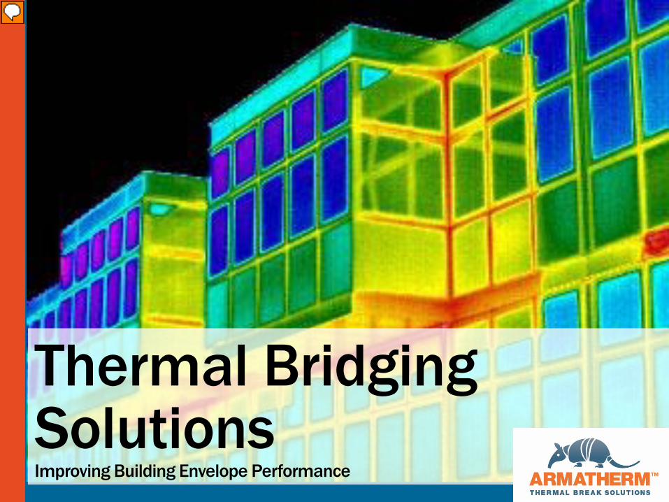
Thermal Bridging Solutions Improving Building Envelope Performance
Thermal Bridging Solutions - … · Course Summary. Thermal bridging is a big concern in the building industry, it has been recognized as a significant factor in building envelop\
Thermal Bridging SolutionsImproving Building Envelope Performance
Presenter
Presentation Notes
Welcome to Thermal Bridging Solutions: Improving Building Envelope Performance sponsored by Armatherm
AIA Best PracticesArmatherm sponsors this program provided by Hanley Wood, a Registered Provider with the American Institute of Architects Continuing Education System (AIA/CES). Credit(s) earned on completion of this program will be reported to AIA/CES for AIA members. Certificates of Completion are available for self-reporting and record-keeping needs upon completion of the program.
This program is registered with AIA/CES for continuing professional education. As such, it does not include content that may be deemed or construed to be an approval or endorsement by the AIA of any materials of construction or any method or manner of handling, using, distributing, or dealing in any material or product.
Questions related to the information within this program should be directed to Armatherm upon completion of this program.
Presenter
Presentation Notes
Armatherm sponsors this program provided by Hanley Wood, a Registered Provider with the American Institute of Architects Continuing Education System (AIA/CES). Credit(s) earned on completion of this program will be reported to AIA/CES for AIA members. Certificates of Completion are available for self-reporting and record-keeping needs upon completion of the program. This program is registered with AIA/CES for continuing professional education. As such, it does not include content that may be deemed or construed to be an approval or endorsement by the AIA of any materials of construction or any method or manner of handling, using, distributing, or dealing in any material or product. Questions related to the information within this program should be directed to Armatherm upon completion of this program.
CopyrightThis presentation is protected by U.S. and International copyright laws. Reproduction, distribution, display, and use of the presentation without written permission from Armathermis prohibited.
This presentation is protected by U.S. and International copyright laws. Reproduction, distribution, display, and use of the presentation without written permission from Armatherm is prohibited.
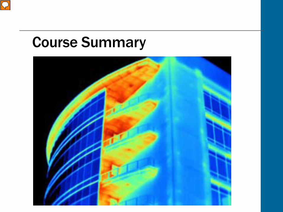
Course Summary
Presenter
Presentation Notes
Thermal bridging is a big concern in the building industry, it has been recognized as a significant factor in building envelope heat loss. By reducing heat flow through a building’s thermal envelope, we can reduce energy consumption as well as prevent potential condensation issues. Building codes have increased requirements of building enclosures requiring ‘continuous insulation’ without thermal bridging. Thermal break materials can be used to reduce heat loss in wall assemblies, transitions, and structural connections throughout the building envelope. They can minimize building energy loss and improve building envelope performance. This course will provide an overview to thermal bridging, discussing the reasons why it occurs as well as how it can be prevented. This course will also compare building details with and without thermal break solutions to highlight the importance of determining accurate values of thermal transmittance.
Learning ObjectivesBy the end of this online learning module, you should be able to:
Define thermal bridging
Describe why thermal bridging occurs
Explain the effects of thermal bridging
Describe how to calculate effective wall assembly U values
Describe the different solutions available to prevent thermal bridging
Presenter
Presentation Notes
By the end of this online learning module, you should be able to: Define thermal bridging Describe why thermal bridging occurs Explain the effects of thermal bridging Describe how to calculate effective wall assembly U values Describe the different solutions available to prevent thermal bridging
Thermal Bridging
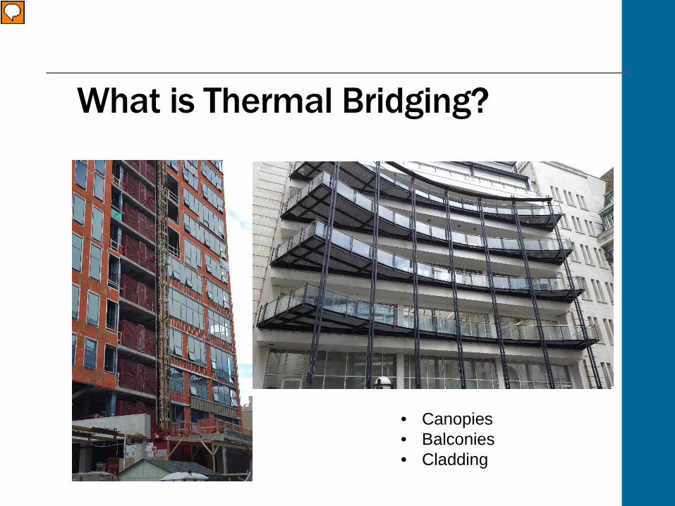
What is Thermal Bridging?
• Canopies• Balconies• Cladding
Presenter
Presentation Notes
So let’s start off by looking at what exactly thermal bridging is. Thermal bridging occurs when structural elements that transfer load from outside the envelope to the main structure, penetrate the thermal envelope. The envelope of a building provides a thermal barrier between the exterior and interior, keeping out moisture as well as resisting the flow of heat through the wall. With envelope design, a building should stay cool during the summer time and warm during winter. A thermal bridge, also known as a cold bridge or heat bridge, is an area of an object (often a building), which has a significantly higher heat transfer than the surrounding materials. This results in an overall reduction in thermal insulation of the object or building. Examples of where thermal bridging can occur are canopies, balconies and cladding attachments. We will look at some of these examples in more detail later on in the course.
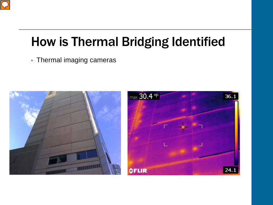
How is Thermal Bridging Identified• Thermal imaging cameras
Presenter
Presentation Notes
Thermal imaging cameras can used to identify thermal bridges in the building envelope. In these examples, the thermal bridges appear as areas of higher temperatures when viewed from the outside of the building. You can see the conductive interface details are where the thermal bridges occur, as there is a higher heat transfer at these locations within wall and roof assemblies.
Key Terms Thermal envelope - all building
elements that totally encase the heated or cooled spaces of a building to resist heat flow between the interior and exterior.
Thermal break - element of low thermal conductivity placed in a system or assembly to reduce or prevent the flow of thermal energy between conductive materials.
Thermal conductivity - Thermal conductivity (k) is the amount of energy a material will conduct in BTU (British Thermal Unit) per hour, per square foot, per inch of thickness, per degree Fahrenheit.
Presenter
Presentation Notes
To help us better understand thermal bridging, we’ll take a look at some of the commonly used key terms and their definitions. Thermal Envelope: is a term used to include all building elements that totally encase the heated or cooled spaces of a building to resist heat flow between the interior and exterior. So everything that separates the inside living space from the outdoors. This includes the walls, roof, slabs on the ground, insulation, weather stripping, caulking, windows and door. Thermal break: this is an element of low thermal conductivity placed in a system or assembly to reduce or prevent the flow of thermal energy between conductive materials. Thermal conductivity: Thermal conductivity (k) is the amount of energy a material will conduct in BTU (British Thermal Unit) per hour, per square foot, per inch of thickness, per degree Fahrenheit. This “k value” is the rate of heat flow through a material. The R value or thermal resistance to heat flow of a material is equal to the material thickness divided by its k value.
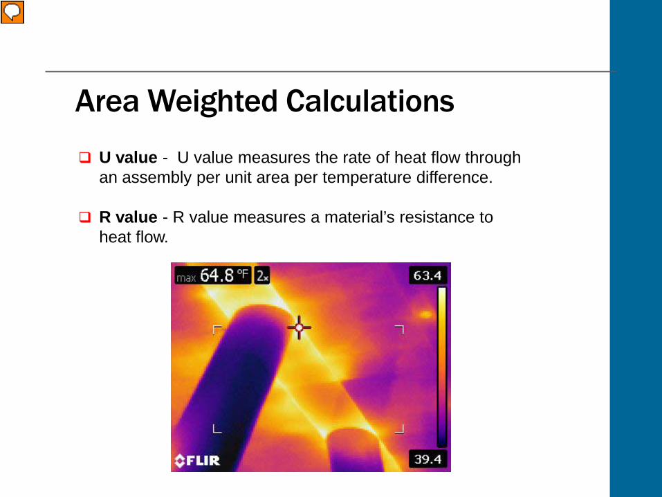
Area Weighted Calculations U value - U value measures the rate of heat flow through
an assembly per unit area per temperature difference.
R value - R value measures a material’s resistance to heat flow.
Presenter
Presentation Notes
Area weighted calculations are commonly used to calculate R and U values of wall assemblies. Typically this is done by weighting the heat flow through the materials by the area the take up. Using the physical area of a thermal bridge assumes the heat flow paths through a detail are one dimensional and parallel. However, highly conductive building materials create lateral or multidirectional heat flows to other components that are not accounted for in parallel heat flow assumptions. Parallel heat flow path assumptions and area weighting do not accurately define the effects of a thermal bridge. U value measures the rate of heat flow through an assembly area per unit temperature. The lower the U value, the more energy efficient the assembly will be. R value measures a material’s resistance to heat flow, so it tells you how well a certain construction material insulates or resists heat flow.
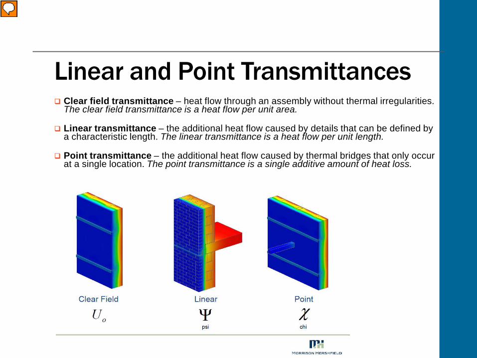
Linear and Point Transmittances Clear field transmittance – heat flow through an assembly without thermal irregularities.
The clear field transmittance is a heat flow per unit area.
Linear transmittance – the additional heat flow caused by details that can be defined by a characteristic length. The linear transmittance is a heat flow per unit length.
Point transmittance – the additional heat flow caused by thermal bridges that only occur at a single location. The point transmittance is a single additive amount of heat loss.
Presenter
Presentation Notes
Using linear and point transmittances simplifies things by ignoring the area of thermal bridges. The heat flow through a wall assembly is compared with and without the thermal bridge detail and the difference in heat flow is related to the thermal bridge bypassing the thermal insulation. The additional heat flow created by a thermal bridge is not dependent on area, rather it is characterized by linear length or a single point within a wall assembly. Linear and point transmittances along with clear field transmittances can be used to determine the overall heat flow for any size wall or roof by calculating effective R and U values that include the effects of thermal bridging. Clear field transmittance: (UO) is the heat flow through a wall, roof or floor assembly which includes the effects of uniformly distributed thermal bridging components such as, brick ties, cladding attachments or framing studs. The clear field transmittance is a heat flow per area. Linear transmittance: (Ψ) is the additional heat flow caused by details that can be defined by a characteristic length. This includes slab edges, parapets, corners, shelf angles and transitions between assemblies. The linear transmittance is a heat flow per length. Point transmittance: (ꭓ) is the additional heat flow caused by thermal bridges that only occur at a single location. This includes canopy, balcony, wind screen, davit and intersections between linear details. The point transmittance is a single additive amount of heat loss.
Examples of Thermal Bridging
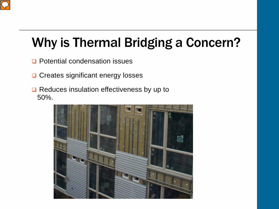
Why is Thermal Bridging a Concern? Potential condensation issues
Creates significant energy losses
Reduces insulation effectiveness by up to 50%.
Presenter
Presentation Notes
Conductive heat transfer through the building thermal envelope creates significant energy losses. In order for us to be able to design and build more energy efficient buildings, we need to address the thermal performance of the building enclosure. Thermal bridges in conventional construction may reduce insulation effectiveness by as much as 50%, resulting in wall assemblies and interface details that do not meet current energy code requirements for minimum U value. Simply adding insulation to walls has proven to not actually decrease the energy use of a building. Thermal bridges allow heat to bypass the insulation, contradicting any benefit of having more insulation in the wall.
Thermal Bridging FactsReduces the R value and insulation effectiveness of a wall
assembly by as much as 50%
18 quadrillion BTU were used in commercial buildings. 19% of total national energy use.
Commercial buildings <25,000ft2 consume 45% of energy used by structures in America.
Thermal bridging is not area dependent
Presenter
Presentation Notes
Let’s now look at some facts. Thermal bridges are inefficiencies within the envelope structure of a building, where heat is transferred at a much higher rate than through the surrounding envelope area. Thermal bridging can reduce the R value of a wall assembly by as much as 50%. The total heat flow through typical wall assemblies is underestimated by as much as 70% due to thermal bridging. Heating and cooling equipment is often oversized, resulting in operational inefficiencies, which means significant energy consumption increases and costs for the building owner. By using thermal bridging solutions, we can maximize energy costs by minimizing the amount of heat transferred through the building envelope. Thermal break materials can be used to reduce heat loss in wall assemblies, transitions and structural connections throughout the building envelope.
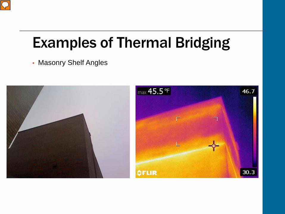
Examples of Thermal Bridging• Masonry Shelf Angles
Presenter
Presentation Notes
There are many different examples of transitions and structural connections where thermal break materials can be used, reducing thermal transmittance and improving envelope U values. Some examples are: Masonry shelf angles Z girt/cladding attachment Balconies Roof penetrations Parapets Wall to wall foundation transition
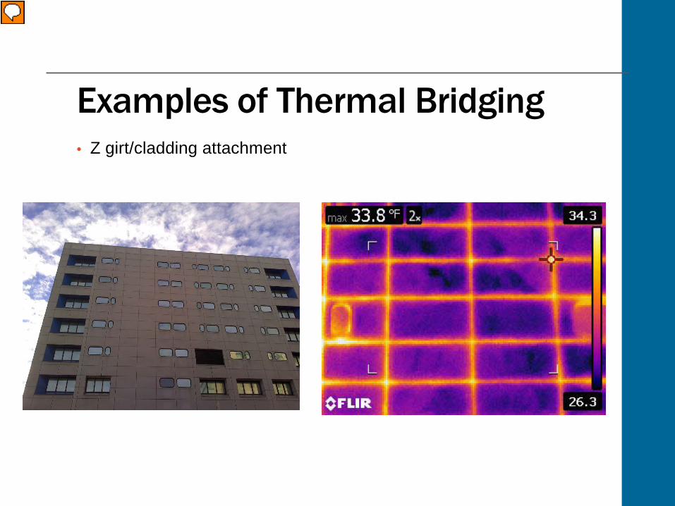
Examples of Thermal Bridging• Z girt/cladding attachment
Presenter
Presentation Notes
There are many different examples of transitions and structural connections where thermal break materials can be used, reducing thermal transmittance and improving envelope U values. Some examples are: Masonry shelf angles Z girt/cladding attachment Balconies Roof penetrations Parapets Wall to wall foundation transition
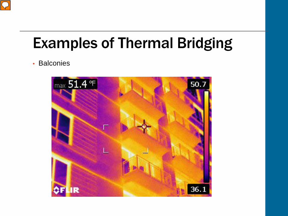
Examples of Thermal Bridging• Balconies
Presenter
Presentation Notes
There are many different examples of transitions and structural connections where thermal break materials can be used, reducing thermal transmittance and improving envelope U values. Some examples are: Masonry shelf angles Z girt/cladding attachment Balconies Roof penetrations Parapets Wall to wall foundation transition
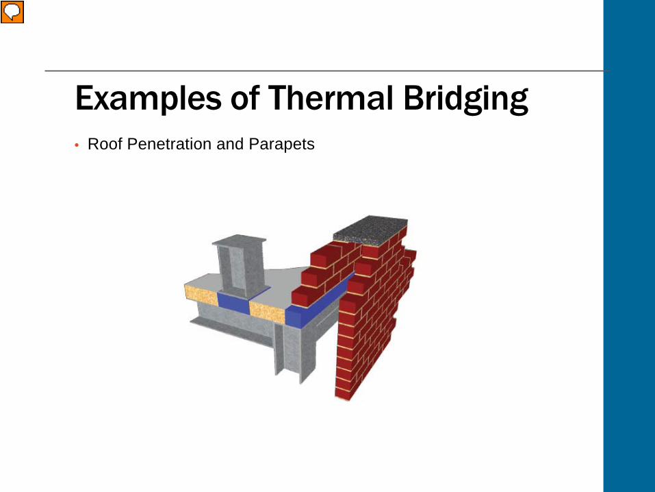
Examples of Thermal Bridging• Roof Penetration and Parapets
Presenter
Presentation Notes
There are many different examples of transitions and structural connections where thermal break materials can be used, reducing thermal transmittance and improving envelope U values. Some examples are: Masonry shelf angles Z girt/cladding attachment Balconies Roof penetrations Parapets Wall to wall foundation transition
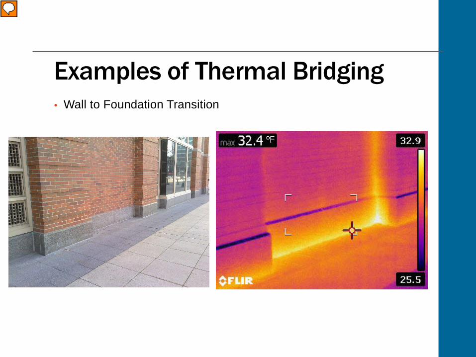
Examples of Thermal Bridging• Wall to Foundation Transition
Presenter
Presentation Notes
There are many different examples of transitions and structural connections where thermal break materials can be used, reducing thermal transmittance and improving envelope U values. Some examples are: Masonry shelf angles Z girt/cladding attachment Balconies Roof penetrations Parapets Wall to wall foundation transition
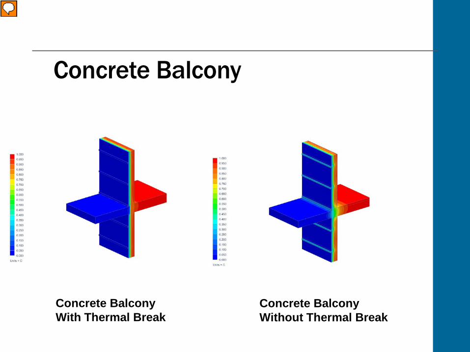
Concrete Balcony
Concrete BalconyWith Thermal Break
Concrete BalconyWithout Thermal Break
Presenter
Presentation Notes
Another good example to look at is a concrete balcony. A concrete balcony that extends the floor slab through the building envelope is an extremely common example of thermal bridging. In order to minimize heat flow and energy loss through the balcony slab, proper thermal break solutions need to be incorporated. For example, cantilevered type balconies can be approximately 3% of the total clear wall area of a building; however 15-30% of the heat flow through the clear wall area is associated with balconies. So in the case of a balcony, heat moves from the floor structure through the wall because there is no thermal break in the floor. By using structural thermal break solutions, balconies will avoid potential condensation issues while keeping the interior space at the desired temperature.
Effects of Thermal Bridging
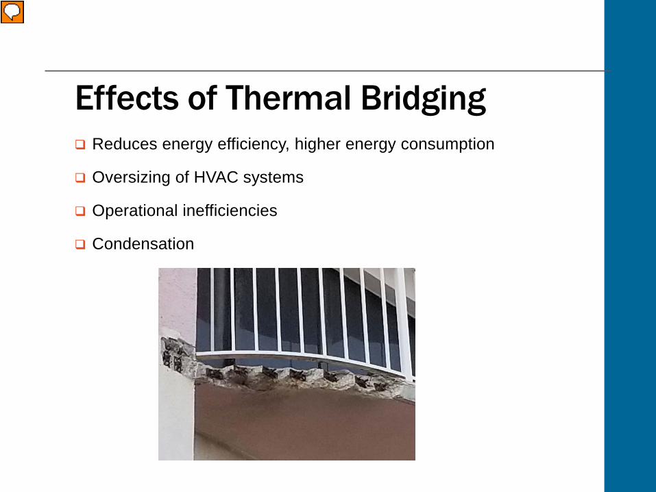
Effects of Thermal Bridging Reduces energy efficiency, higher energy consumption
Oversizing of HVAC systems
Operational inefficiencies
Condensation
Presenter
Presentation Notes
Thermal bridging affects several aspects of building design. One of the biggest issues is that it reduces the overall thermal efficiency of the building envelope, resulting in higher energy consumption. Because of this, HVAC systems need to be oversized which causes operational inefficiencies. Thermal bridging can also cause condensation, which can corrode metal and deteriorate concrete. Let’s look at condensation in more detail.
Condensation Appears when the temperature at the internal surface of
an external wall is at or below the dew point temperature.
How can we reduce the risk of condensation?oUsing thermal break materials and vapor barriers o Force the dew point outward of the thermal envelope
Presenter
Presentation Notes
So what causes condensation and why is it such a big concern? Thermal bridges can reduce the surface temperature on internal surfaces as they penetrate the thermal envelope. This can result in potential moisture problems. Over time, moisture within the building structure can corrode metal, rot wood, deteriorate concrete over time and allow mold to grow. In cold climates, moisture can collect on the internal surfaces of exterior walls. When these surfaces become too cold due to a thermal bridge, the relative humidity of the air could exceed 65%. The higher the relative humidity, the greater the water vapor content. Condensation will occur on cold surface areas when the temperature at the internal surface of an external wall is at or below the dew point temperature of the air. How can it be prevented? Thermally efficient building envelopes using both thermal break materials and vapor barriers will help reduce the risk of condensation, by forcing the dew point outward of the thermal envelope. A thermally broken structural connection will prevent excessive heat flow and potential condensation problems.
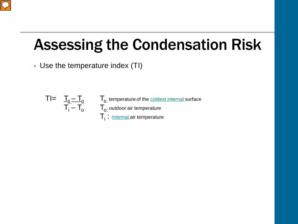
Assessing the Condensation Risk• Use the temperature index (TI)
Ts – ToTi – To
TI= Ts: temperature of the coldest internal surface
To: outdoor air temperature
Ti : Internal air temperature
Presenter
Presentation Notes
Using the temperature index (TI) is one way to assess condensation risk and prevent the negative effects associated with it. The TI can be used to predict whether condensation will occur by comparing the coldest interior surface temperature to the dew point temperature. Condensation will occur if the interior surface temperature is less than the dew point temperature. The temperature index is the ratio of the temperature difference between the inside surface temperature and the outside air temperature, divided by temperature difference between inside and outside air.
Quantifying the Effect of Thermal Bridging
Quantifying Impact of Heat Loss
Presenter
Presentation Notes
In order to be able to address heat loss issues, you need to be able to quantify the impact of heat loss on building performance. This will help reduce costs and energy consumption as well as improving the performance of the building envelope. So how can you best quantify the impact of heat loss on building performance? Click next to find out!
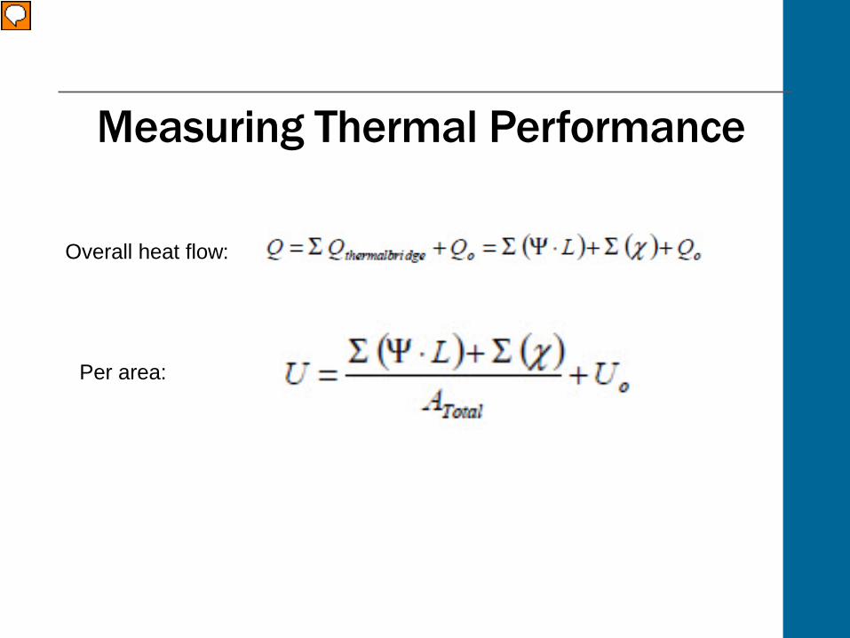
Measuring Thermal Performance
Overall heat flow:
Per area:
Presenter
Presentation Notes
Lets now look at how you can use the effective R and U values to accurately measure thermal performance. Linear and point transmittances along with clear field transmittances can be used to determine the overall heat flow for any size wall or roof by calculating effective R and U values that include the effects of thermal bridging. For whole building load calculations, the linear and point transmittances are simply added to the clear field U value of a given assembly area to calculate the overall thermal transmittance. The overall heat flow can be found by adding all of the components together as shown below. Q=Q thermal bridges+ Q O = ∑ (Ψ * L) + ∑ (ꭓ) + Q Or, as heat flow per area: U=∑ (Ψ * L) + ∑ (ꭓ)A + U O Where A, is the total opaque wall area.
Thermal Break Solutions
Solutions to Prevent Thermal Bridging Low thermal conductivity materials
Thermoplastics
High strength materials
Thermoset materials
Presenter
Presentation Notes
We have looked at what causes thermal bridging and the damaging effects it can have so now we’ll look at what solutions are available to improve the building envelope performance. To be able to design and build more energy efficient buildings, we need to address the thermal performance of the building enclosure. First, lets look at what materials you should and shouldn’t use to prevent thermal bridges. Click next to find out more.
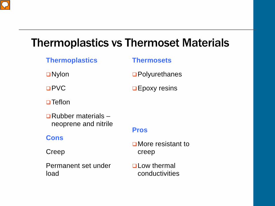
Thermoplastics vs Thermoset MaterialsThermoplastics
Nylon
PVC
Teflon
Rubber materials –neoprene and nitrile
Cons
Creep
Permanent set under load
Thermosets
Polyurethanes
Epoxy resins
Pros
More resistant to creep
Low thermal conductivities
Presenter
Presentation Notes
Thermoplastics such as nylon, PVC and Teflon as well as rubber materials such as neoprene and nitrile can have low thermal conductivities. This is good but these materials deflect, creep and take a permanent set under load. In a structural connection this is not suitable so other materials should be used. Compare this to thermoset materials such as polyurethanes and epoxy resins. They are ideal for use as thermal breaks because they are much more resistant to creep and deformation under load while also having low thermal conductivities.
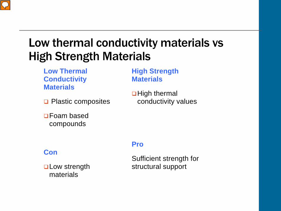
Materials with low thermal conductivities can be manufactured/engineered from a wide array of plastic composites and elastomeric or foam based compounds. In thermally broken, structural connections such as cladding attachments, canopies and balconies, materials used as thermal breaks must have high strength, stiffness and creep resistance. High strength materials however tend to have high thermal conductivity values, whereas low strength materials tend to have low thermal conductivity values. The most effective thermal break solutions will need to have a sufficient strength for structural support as well as a low thermal conductivity capable of reducing heat flow and preventing a thermal bridge.
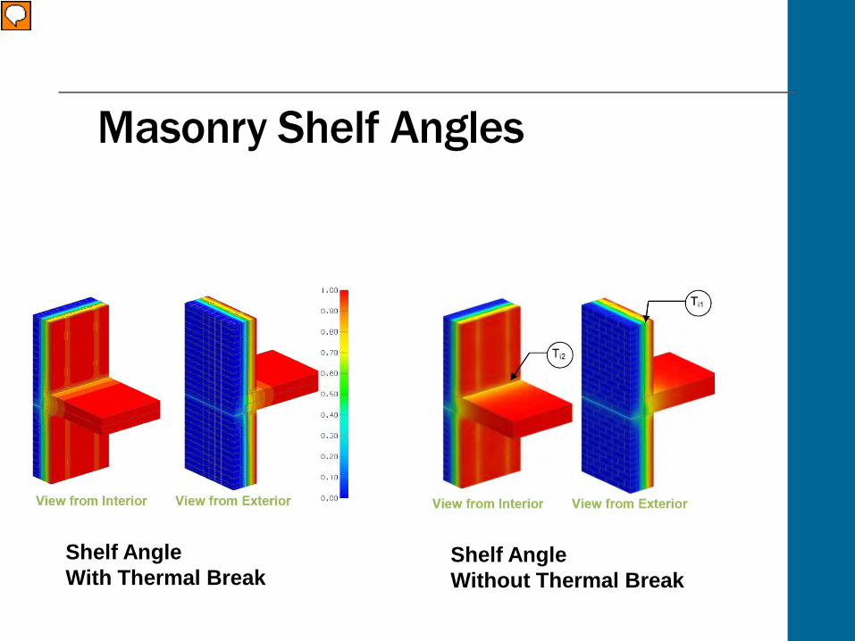
Masonry Shelf Angles
Shelf AngleWith Thermal Break
Shelf AngleWithout Thermal Break
Presenter
Presentation Notes
On screen now you will see different examples of building interface details with and without thermal break solutions. Let’s now take a look at some examples of thermal bridging in more detail. Masonry veneer walls require tie-backs and shelf angles which form significant thermal bridges and can reduce a walls’ R value by as much as 60% which makes it very difficult to meet energy codes. Shelf angles transfer the masonry load back to the buildings’ structural steel or concrete slab edge interrupting the continuous insulating layer of the wall assembly creating a continuous thermal bridge.
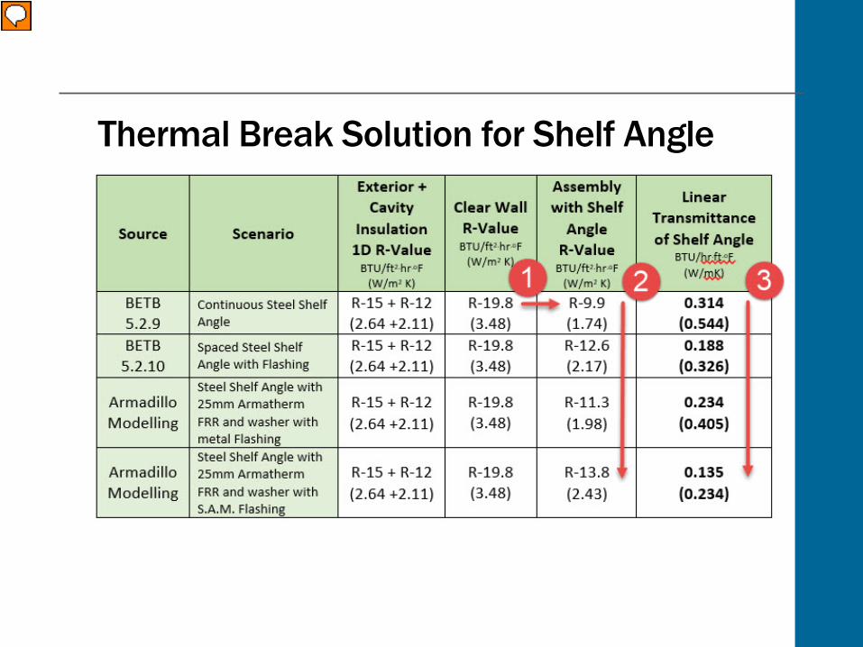
Thermal Break Solution for Shelf Angle
Presenter
Presentation Notes
Looking at the thermal modeling results of a typical shelf angle, you can see that the R value and consequently the U value of wall assembly decrease by 50% when including the effect of the slab edge and shelf angle. This shows that half of the heat loss in this wall assembly is due to the shelf angle. Now compare the values when a thermal break solution is used behind the shelf angle. The R value is increased by 28%, while the heat flow per unit length (linear transmittance) is reduced by 57%.
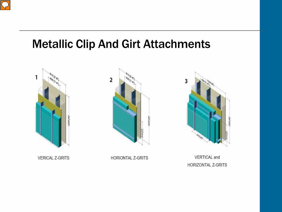
Metallic Clip And Girt Attachments
Presenter
Presentation Notes
It has been demonstrated that metal Z girts are responsible for 45% - 50% of the heat flow through conventional steel stud wall assemblies with exterior cladding. Adding layers of insulation is not effective enough in creating effective U values that meet current energy codes. Using non-conductive clips and girts make the exterior insulation up to 98% efficient reducing heat loss and improving the clear field U value of the wall assembly.
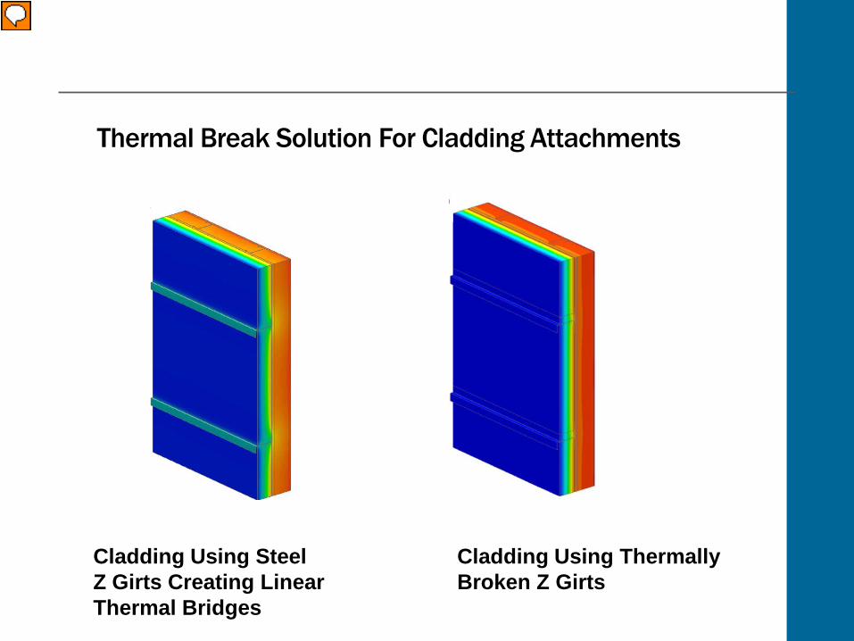
Thermal Break Solution For Cladding Attachments
Cladding Using ThermallyBroken Z Girts
Cladding Using SteelZ Girts Creating LinearThermal Bridges
Presenter
Presentation Notes
It has been demonstrated that metal Z girts are responsible for 45% - 50% of the heat flow through conventional steel stud wall assemblies with exterior cladding. Adding layers of insulation is not effective enough in creating effective U values that meet current energy codes. Using non-conductive clips and girts make the exterior insulation up to 98% efficient reducing heat loss and improving the clear field U value of the wall assembly.
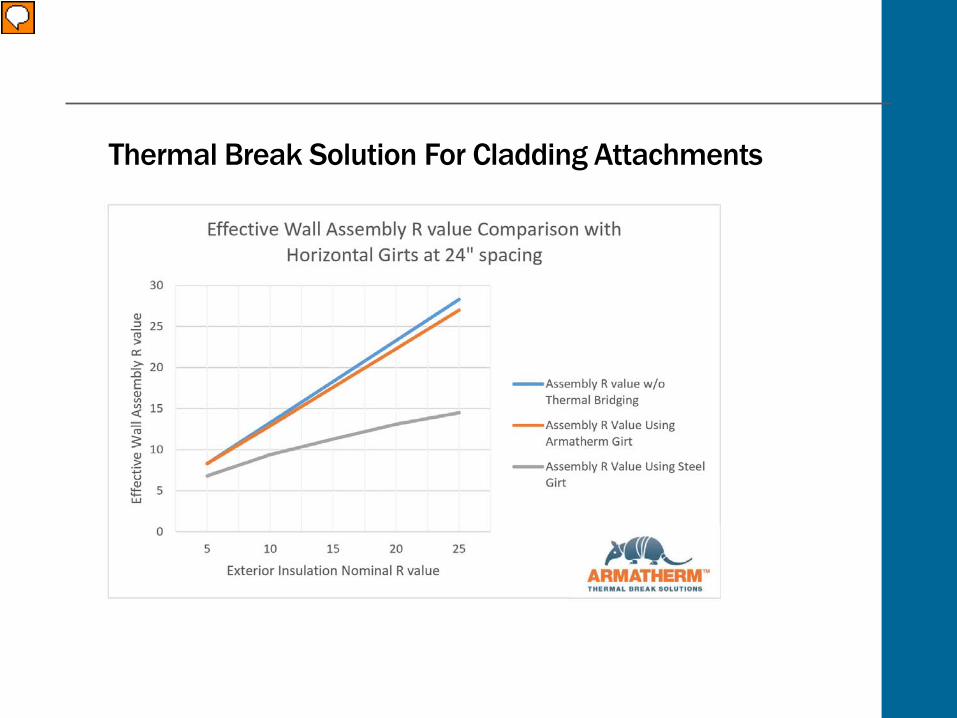
Thermal Break Solution For Cladding Attachments
Presenter
Presentation Notes
It has been demonstrated that metal Z girts are responsible for 45% - 50% of the heat flow through conventional steel stud wall assemblies with exterior cladding. Adding layers of insulation is not effective enough in creating effective U values that meet current energy codes. Using non-conductive clips and girts make the exterior insulation up to 98% efficient reducing heat loss and improving the clear field U value of the wall assembly. The R value of a wall assembly can be reduced by as much as 60% when a balcony or canopy interface detail passes through the thermal envelope creating a thermal bridge. When a properly designed, structural thermal break is used in the connection, the point transmittance (heat flow) at these connections can be reduced by over 50% significantly improving the U value of the wall assembly.
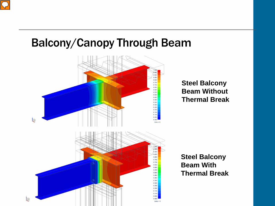
Balcony/Canopy Through Beam
Steel Balcony Beam Without Thermal Break
Steel Balcony Beam With Thermal Break
Presenter
Presentation Notes
The R value of a wall assembly can be reduced by as much as 60% when a balcony or canopy interface detail passes through the thermal envelope creating a thermal bridge. When a properly designed, structural thermal break is used in the connection, the point transmittance (heat flow) at these connections can be reduced by over 50% significantly improving the U value of the wall assembly.
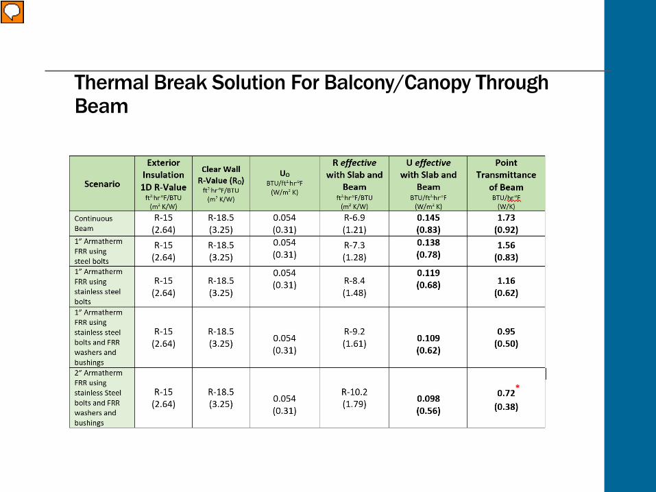
Thermal Break Solution For Balcony/Canopy Through Beam
Presenter
Presentation Notes
The R value of a wall assembly can be reduced by as much as 60% when a balcony or canopy interface detail passes through the thermal envelope creating a thermal bridge. When a properly designed, structural thermal break is used in the connection, the point transmittance (heat flow) at these connections can be reduced by over 50% significantly improving the U value of the wall assembly.
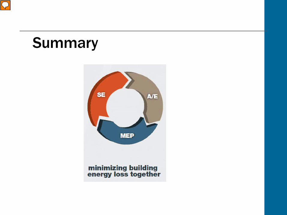
Summary
Presenter
Presentation Notes
In summary, thermal bridging and improving building envelope efficiency is gaining awareness. In order to change current practice for dealing with thermal bridging, communication between all members of the design team is essential. In the past, the effects of thermal bridging were difficult to define. In addition to the heat flow normally transmitted through the building envelope (air leakage for example) multi directional heat flows are created at thermal bridge locations. Therefore, the use of effective R and U values rather than nominal values is a more accurate measure of thermal performance. By properly identifying all of the inefficient aspects of a building’s structure and by using thermal break solutions, thermal bridging can be prevented. This could result in reduced heat loss by as much as 70%, as well as reduced cost and energy consumption all while improving the performance of the building envelope.
Thank YouThank you for your interest in Thermal Bridging Solutions: Improving Building Envelope Performance sponsored by Armatherm.
For more information, please contact:
http://www.Armatherm.com
Presenter
Presentation Notes
Thank you for your interest in Thermal Bridging Solutions to Improve Building Envelope Performance sponsored by Armatherm. For more information, please contact: http://www.Armatherm.com
Quiz InstructionsYou will now complete a 10-question quiz. To earn credit on this learning unit, you must answer 8 of 10 questions correctly to achieve a passing score. You will receive feedback immediately after each question. If you answer more than two questions incorrectly you will be able to finish the quiz, but upon completion you will be given the opportunity to return to the beginning of the quiz for another attempt.
Click Next to begin.
CompletionYou have completed this course attempt. If you did not pass the quiz, you may go back and retry by clicking on the “Retry Quiz” button. If you passed the quiz, you may exit the course by clicking on the “x” in the top right corner of the course player window.