Embed Size (px)
Citation preview
Department of Physics, Chemistry and Biology
Master’s Thesis
Thermal Stability of Arc Evaporated ZrCrAlN
Syed Muhammad Bilal Nanostructured Materials
2012/08/28
LITH-IFM-A-EX--12/2700—SE
Linköpings universitet Institutionen för fysik, kemi och biologi 581 83 Linköping

© Syed Muhammad Bilal
Institutionen för fysik, kemi och biologi
Thermal Stability of Arc Evaporated ZrCrAlN
Syed Muhammad Bilal
Nanostructured Materials
2012/08/28
Handledare
Rikard Forsén & Naureen Ghafoor
Examinator Magnus Odén

Datum Date : 2012/08/28
Avdelning, institution Division, Department Nanostructured Material Group Department of Physics, Chemistry and Biology Linköping University
URL för elektronisk version
ISBN ISRN: LITH-IFM-A-EX--12/2700--SE _________________________________________________________________ Serietitel och serienummer ISSN Title of series, numbering LITH-IFM-A-EX-12/2700-SE
Språk Language
Svenska/Swedish Engelska/English
________________
Rapporttyp Report category
Licentiatavhandling Examensarbete C-uppsats D-uppsats Övrig rapport
_____________
Titel Title Thermal Stability of Arc Evaporated ZrCrAlN Författare Author
Syed Muhammad Bilal
Nyckelord Keyword Thermal Stability, ZrCrAlN, Reactive Cathodic Arc Evaporation, Anneal, Age Hardening, XRD, EDS, Nanoindentation, Hardness.
Sammanfattning Abstract
This research explores the thermal stability of ZrCrAlN material system. For this purpose fourteen different
compositions of ZrCrAlN coatings were deposited onto tungsten carbide substrates by using reactive cathodic arc
evaporation. These compositions were further annealed at 800oC, 900oC, 1000oC and 1100oC temperatures. EDS was
employed to specify the compositions. The crystal structure of the coatings were analysed by XRD, and the hardness
of these coatings was determined by Nanoindentation. The experimental findings reported a significant age hardening
of Zr0.16Cr0.12Al0.72N and a delayed h-AlN formation in Zr0.07Cr0.40Al0.52N. ZrCrAlN was thus proved to be thermally
stable.

i
Abstract
This research explores the thermal stability of ZrCrAlN material system. For this purpose
fourteen different compositions of ZrCrAlN coatings were deposited onto tungsten carbide
substrates by using reactive cathodic arc evaporation. These compositions were further
annealed at 800oC, 900oC, 1000oC and 1100oC temperatures. EDS was employed to specify
the compositions. The crystal structure of the coatings were analysed by XRD, and the
hardness of these coatings was determined by Nanoindentation. The experimental findings
reported a significant age hardening of Zr0.16Cr0.12Al0.72N and a delayed hAlN formation in
Zr0.07Cr0.40Al0.52N. ZrCrAlN was thus proved to be thermally stable.

ii

iii
Acknowledgement
A Large number of people have contributed directly and indirectly to the completion of this research thesis. It is a pleasure to convey my gratitude to them all in my humble acknowledgement.
Rikard Forsén, my supervisor, who guided me from the very early stage of this research and taught me the real meaning of research. His constructive criticism and heartfelt words of encouragement are invaluable. I am indebted to him more than he knows.
Naureen Ghafoor, my co-supervisor. Her supervision and crucial contribution made her a backbone of this research and so to this thesis.
Magnus Odén, my group leader and examiner for all the constructive comments on the thesis. His generous decision to send me to Seco Tools helped me understand the reactive cathodic arc evaporation system.
Robert Pilemalm, for teaching me EDS and XRD, as well as showing me how to play Risk.
Lina Rogström, Axel Knutsson, Niklas Norrby, Phani Kumar, Jennifer Ullbrand, Jianqiang Zhu, Mats Johansson and all the friends in thinfilm group for always being available for discussions.
Linjing Liu, for proofreading my thesis and the positive criticism.
Friends in Pakistan, Germany and Sweden, for their continuous support.
My Family, for all the prayers and making my life colourful.

iv
v
Contents
Abstract .................................................................................................................................................... i
Acknowledgement ................................................................................................................................. iii
1. Introduction ................................................................................................................................... 1
1.1 Background ............................................................................................................................. 1
1.2 Objectives ............................................................................................................................... 2
2. Theory ............................................................................................................................................ 3
2.1 Metal Cutting .......................................................................................................................... 3
2.1.1 Cemented Carbide ........................................................................................................... 4
2.2 Thin Film Deposition Techniques ........................................................................................... 4
2.2.1 Chemical Vapour Deposition .......................................................................................... 5
2.2.2 Physical vapour Deposition ............................................................................................ 5
2.2.2.1 Cathodic Arc Evaporation ........................................................................................... 5
3. Material Systems ........................................................................................................................... 9
3.1 Binary Nitride Systems ......................................................................................................... 10
3.1.1 Zr-N System .................................................................................................................. 10
3.1.3 Al-N System .................................................................................................................. 11
3.2 Ternary Systems of Nitrides ................................................................................................. 11
3.2.1 Zr-Al-N System............................................................................................................. 11
3.2.2 Cr-Al-N System ............................................................................................................ 12
4. Analysis Techniques .................................................................................................................... 13
4.1 Energy Dispersive X-ray Spectrometry (EDS) ..................................................................... 13
4.2 X-ray Diffraction (XRD) ...................................................................................................... 15
vi
4.2.1 θ-2θ Scan .............................................................................................................................. 16
4.3 Nanoindentaion ..................................................................................................................... 17
5. Experimental Details................................................................................................................... 21
6. Results and Discussion ................................................................................................................ 23
6.1 Compositions ........................................................................................................................ 23
6.2 General Trends of As-Deposited Hardness vs. Zr Content ................................................... 24
6.2.1 40%Al ........................................................................................................................... 25
6.2.2 50%Al ........................................................................................................................... 27
6.2.3 70%Al ........................................................................................................................... 28
6.3 Thermal Stability .................................................................................................................. 29
6.3.1 ZrAlN ............................................................................................................................ 29
6.3.2 CrAlN ............................................................................................................................ 32
6.4 Structural Information ................................................................................................................. 36
7. Conclusion ................................................................................................................................... 39
8. Future Outlook ............................................................................................................................ 41
9. References .................................................................................................................................... 43
1
1. Introduction
1.1 Background
Coatings have multifarious applications in today’s world. The gamut of applications includes
decorative coatings like coatings on watches, electrically conductive coatings as the ones
used for electrical contacts, the protective coatings such as hard coatings on tools to reduce
wear etc.
The industrial demand for higher turning speeds exposes the hard coatings to extreme
conditions of high temperature and high pressure during the cutting operations. Only those
coatings which show thermal stability are suitable candidates under these rugged conditions.
Ternary Nitride coatings such as TiAlN and CrAlN have long established reputation as the
preferred choice for hard coatings on cutting tools. TiAlN and ZrAlN coatings exhibit
significant age hardening when annealed at higher temperatures and have good resistance to
oxidation. CrAlN coatings show weak age hardening and exhibit extremely good oxidation
resistance. The age hardening in TiAlN coatings is caused by the formation of coherent cubic
TiN and AlN rich domains during spinodal decomposition [1]. The age hardening in ZrAlN is
ascribed to the nucleation and growth of nanocrystalline cubic ZrAlN surrounded by an
amorphous phase [2]. In the case of CrAlN the age hardening is observed for low
temperatures due to AlN precipitation close to grain boundaries [3]. However as both Al and
2
Cr form good protective oxides suppressing further oxygen diffusion these coatings offer
better oxidation resistance comared to TiAlN [4].
Recently the research in multinary nitride coatings has shown improved wear resistance as
well as better oxidation resistance under high temperatures as compared to the ternary nitride
coatings. This opens a new vista into the research of multinary coatings. TiCrAlN has already
shown better wear resistance than TiAlN and CrAlN [5]. Similarly ZrCrAlN is also an
auspicious candidate which needs to be explored.
1.2 Objectives
The purpose of this thesis is to explore the thermal stability of the ZrCrAlN material system.
This is carried out by depositing fourteen different compositions of ZrCrAlN coatings onto
WC-Co substrates with reactive cathodic arc evaporation. The annealing of these samples is
then carried out at a temperature range of 800 oC-1100 oC with an increment of 100 oC. The
compositions of the coatings were established by EDS. XRD is used to determine the crystal
structure of the coatings and nanoindentation is done to determine the hardness of these
coatings.
3
2. Theory
2.1 Metal Cutting
To harness the benefits offered by metals, they need to be cut and shaped. To cut and shape
the metals, tools are required. The ideal tool material should have the following properties:
• Harder than the work piece.
• High Toughness.
• Chemically inert to the work piece.
• Can withstand thermal shocks.
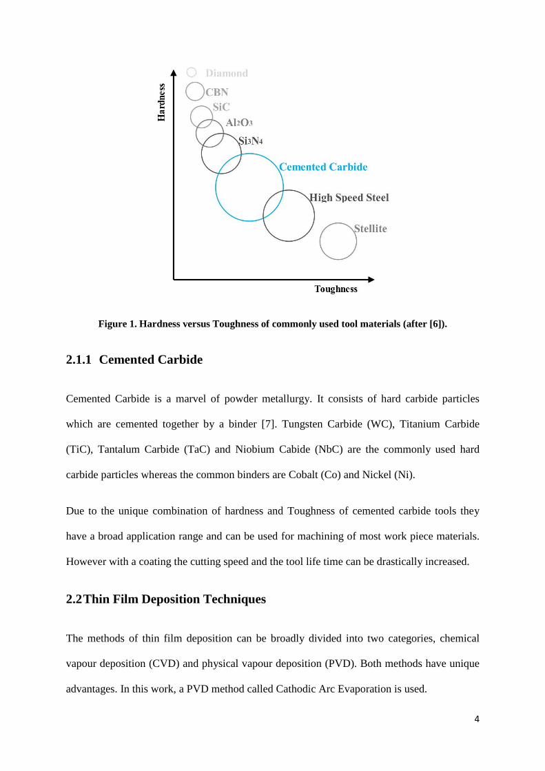
Cemented Carbide is the material that strikes a good balance among the above mentioned
properties as shown in fig1.
4
Figure 1. Hardness versus Toughness of commonly used tool materials (after [6]).
2.1.1 Cemented Carbide
Cemented Carbide is a marvel of powder metallurgy. It consists of hard carbide particles
which are cemented together by a binder [7]. Tungsten Carbide (WC), Titanium Carbide
(TiC), Tantalum Carbide (TaC) and Niobium Cabide (NbC) are the commonly used hard
carbide particles whereas the common binders are Cobalt (Co) and Nickel (Ni).
Due to the unique combination of hardness and Toughness of cemented carbide tools they
have a broad application range and can be used for machining of most work piece materials.
However with a coating the cutting speed and the tool life time can be drastically increased.
2.2 Thin Film Deposition Techniques
The methods of thin film deposition can be broadly divided into two categories, chemical
vapour deposition (CVD) and physical vapour deposition (PVD). Both methods have unique
advantages. In this work, a PVD method called Cathodic Arc Evaporation is used.
5
2.2.1 Chemical Vapour Deposition
Chemical vapour deposition, as the name suggests, is the process involving chemical
reactions. In CVD the coating materials are introduced in the chamber in gaseous phases
which chemically react to form the desired composition of the coating on the heated
substrate. The advantage of the material being in a gaseous phase is that the complex shapes
can be coated easily.
In conventional CVD the deposition of coatings is carried out at temperatures greater than
1000 oC. Decarbonisation of cemented carbide is catalysed at such a high temperature which
leads to the decrease in toughness of the tool. [8]. Due to the involvement of high
temperatures during the CVD processes it is difficult to deposit coatings in metastable state.
2.2.2 Physical vapour Deposition
In conventional physical vapour deposition processes, the physical processes like evaporation
and condensation are involved for the deposition of the film onto the substrate. The
deposition process can be carried out at room temperature. This gives it an edge over the
CVD for the deposition of metastable coatings. There are several PVD techniques for
deposition of hard coatings like magnetron sputtering and cathodic arc evaporation.
2.2.2.1 Cathodic Arc Evaporation
In this technique the cathode which is made of the material to be deposited is struck by a high
current and low voltage arc. This high current and low voltage discharge melts the cathode
surface locally and this localized point is referred to as the cathode spot [9]. From this
cathode spot the molten material is vaporized into plasma which is transported to the
substrate. The cathode spot is only active for 10 ns-1µs and leaves a crater on the cathode
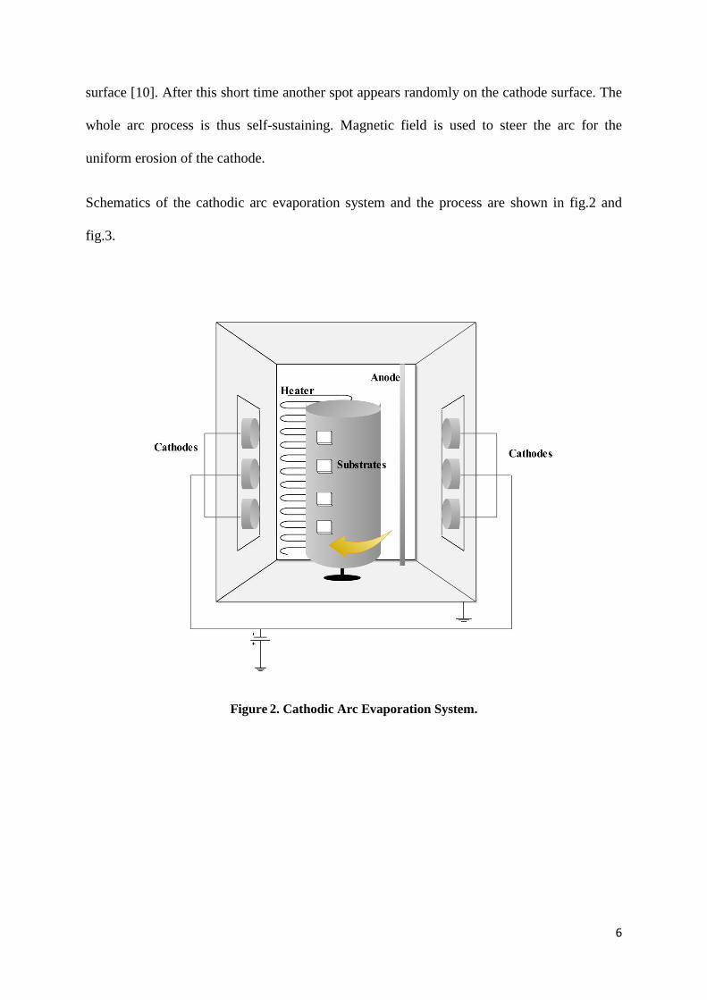
6
surface [10]. After this short time another spot appears randomly on the cathode surface. The
whole arc process is thus self-sustaining. Magnetic field is used to steer the arc for the
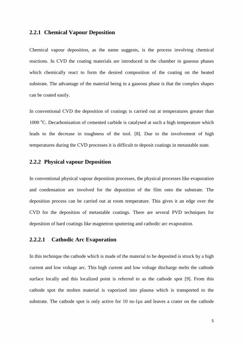
uniform erosion of the cathode.
Schematics of the cathodic arc evaporation system and the process are shown in fig.2 and
fig.3.
Figure 2. Cathodic Arc Evaporation System.
7
Figure 3. Cathodic Arc Evaporation Process (after [11]).

8
9
3. Material Systems
The earliest material system of ceramic coatings for cutting tools was TiN. TiN improves the
cutting performance of cutting tools [12]. However TiN has limited stability at elevated
temperatures. Oxidation of these coatings is initiated around 600 oC [13]. Al was then added
to this system which resulted in improved high temperature properties [14]. The new material
system TiAlN showed superior oxidation resistance and better machining performance [14].
This motivated to study other binary metal nitride systems with the addition of aluminium.
The new ternary metal aluminium nitride systems e.g. CrAlN [15], ZrAlN [16], ScAlN[17]
and HfAlN[18] showed better results than their parent binary nitride systems.
CrAlN shows better oxidation resistance than TiAlN [19] whereas TiAlN system exhibit age
hardening with improved high temperatue mechanical properties [1]. Thus the researchers
attempted to blend these material systems in order to culminate the benefits of both systems
into one system. This has taken the research into the domain of multinary nitride systems.
The new material system TiCrAlN proved better than TiAlN and CrAlN [5, 20].
10
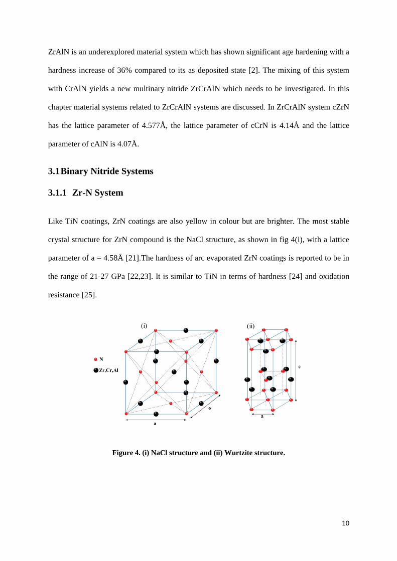
ZrAlN is an underexplored material system which has shown significant age hardening with a
hardness increase of 36% compared to its as deposited state [2]. The mixing of this system
with CrAlN yields a new multinary nitride ZrCrAlN which needs to be investigated. In this
chapter material systems related to ZrCrAlN systems are discussed. In ZrCrAlN system cZrN
has the lattice parameter of 4.577Å, the lattice parameter of cCrN is 4.14Å and the lattice
parameter of cAlN is 4.07Å.
3.1 Binary Nitride Systems
3.1.1 Zr-N System
Like TiN coatings, ZrN coatings are also yellow in colour but are brighter. The most stable
crystal structure for ZrN compound is the NaCl structure, as shown in fig 4(i), with a lattice
parameter of a = 4.58Å [21].The hardness of arc evaporated ZrN coatings is reported to be in
the range of 21-27 GPa [22,23]. It is similar to TiN in terms of hardness [24] and oxidation
resistance [25].
Figure 4. (i) NaCl structure and (ii) Wurtzite structure.
11
3.1.2 Cr-N System
CrN coatings have a metallic silver colour. The crystal structure of these coatings depends
upon the deposition conditions. The metastable crystal structure of CrN coatings is NaCl
structure, as shown in fig4(i), with a lattice constant of a = 4.14Å [26]. CrN coatings also
exhibit a stable wurtzite structure as shown in fig4(ii), depending on the growth conditions
[27], with lattice parameters of a = 4.81Å [28] and c = 4.48 Å [28]. CrN coatings offer better
oxidation resistance than TiN [29]. As the crystal structure in these films strongly depend on
the deposition conditions so is the hardness [30].These coatings show hardness in a broad
range of 12-30GPa [30].
3.1.3 Al-N System
AlN primarily has recognition as a wide band gap semiconductor material for electronic
applications and is not used as a hard protective coating. The Wurtzite structure, shown in
fig.4(ii), is the equilibrium structure of this material with lattice parameters a = 3.11Å [31]
and c = 4.98Å [31]. Besides wurtzite structure it can also exist in metastable state as a cubic
NaCl structure, shown in fig. 4(i), with lattice constant of a = 4.05Å [32].
3.2 Ternary Systems of Nitrides
3.2.1 Zr-Al-N System
Theoretical studies have shown that ZrAlN exhibits a higher miscibility gap than TiAlN and
CrAlN [33]. It has been shown that for x ≤ 0.36 at. % in Zr1-xAlxN, i.e. low Al content, the
cubic phase is stable [34]. For x > 0.70 at %, i.e. high Al content, hexagonal structure is
12
promoted [34]. Whereas for intermediate Al contents a mixture of cubic, hexagonal and
amorphous structure exists [34].
3.2.2 Cr-Al-N System
CrAlN coatings are used for high temperature oxidation resistance applications. CrAlN films
can be obtained in a wide range of compositions due to the high solubility of CrN in AlN
[35]. Its crystal structure is shown to have a cubic NaCl structure in the range of x = 60-70
at.% [36]. For x ranging from.70 at.% to 83 at. % the structure is a mixture of cubic and
wurtzite [36]. For x > 83 at.% the structure completely transforms to wurtzite during the
deposition [36]. Coatings with cubic (NaCl) structure have shown age around 700 oC. As
soon as the temperature increases beyond 900 oC the structure transforms to hexagonal, i.e.
wurtzite, and the mechanical properties depreciate [37]. The as-deposited value for these
coatings is ~30GPa [38]. The coatings with a cubic structure have shown superior oxidation
resistance due to the formation of complex oxides at elevated temperatures [37].
13
4. Analysis Techniques
Different combinations of techniques have been employed for the analysis of the coatings.
The techniques provide valuable information regarding chemical composition, microstructure
and mechanical properties.
4.1 Energy Dispersive X-ray Spectrometry (EDS)
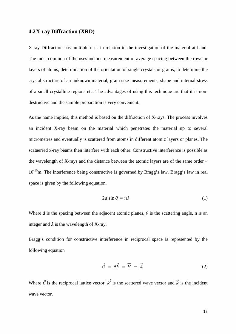
EDS relies on X-ray spectrum emitted by a sample as it is being bombarded with a focused
electron beam to obtain a localized chemical analysis. Elements from atomic number 4(Be) to
92(U) can be detected with this technique. The depth resolution of this technique is 0.3-5µm.
The process involves a focused beam of highly energetic electrons, in the range of keV,
incident on the specimen. The different species that can be witnessed besides X-rays as the
sample is bombarded with an electron beam are shown in fig 6. This incident beam of
electron may knock out an electron from the inner shell of atom within the sample and thus
creating a hole as shown in fig 5. An electron from the outer shell then fills this hole. The
difference in energy between the outer shell and the inner shell can be released as X-rays.
The emitted X-ray photon is then registered by the energy dispersive spectrometer. Since
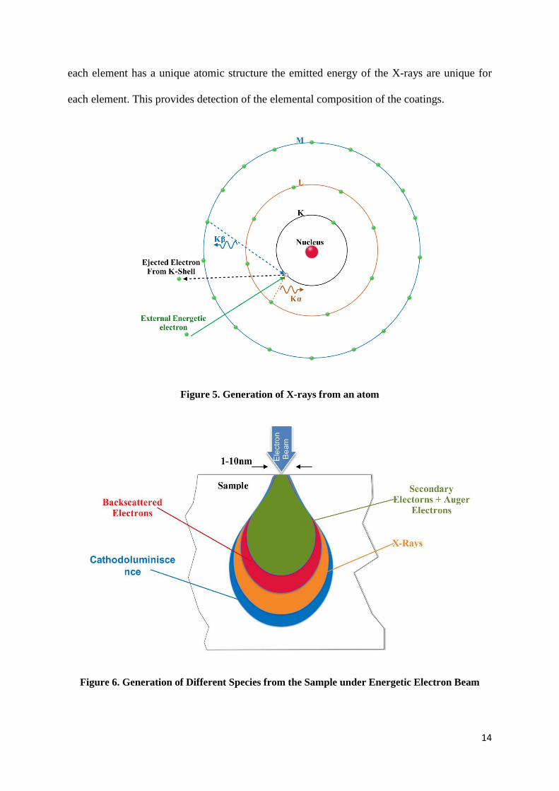
14
each element has a unique atomic structure the emitted energy of the X-rays are unique for
each element. This provides detection of the elemental composition of the coatings.
Figure 5. Generation of X-rays from an atom
Figure 6. Generation of Different Species from the Sample under Energetic Electron Beam
15
4.2 X-ray Diffraction (XRD)
X-ray Diffraction has multiple uses in relation to the investigation of the material at hand.
The most common of the uses include measurement of average spacing between the rows or
layers of atoms, determination of the orientation of single crystals or grains, to determine the
crystal structure of an unknown material, grain size measurements, shape and internal stress
of a small crystalline regions etc. The advantages of using this technique are that it is non-
destructive and the sample preparation is very convenient.
As the name implies, this method is based on the diffraction of X-rays. The process involves
an incident X-ray beam on the material which penetrates the material up to several
micrometres and eventually is scattered from atoms in different atomic layers or planes. The
scataerred x-ray beams then interfere with each other. Constructive interference is possible as
the wavelength of X-rays and the distance between the atomic layers are of the same order ~
10-10m. The interference being constructive is governed by Bragg’s law. Bragg’s law in real
space is given by the following equation.
2𝑑 sin𝜃 = 𝑛𝜆 (1)
Where d is the spacing between the adjacent atomic planes, θ is the scattering angle, n is an
integer and 𝜆 is the wavelength of X-ray.
Bragg’s condition for constructive interference in reciprocal space is represented by the
following equation
�⃗� = ∆𝑘�⃗ = 𝑘′���⃗ − 𝑘�⃗ (2)
Where �⃗� is the reciprocal lattice vector, 𝑘′���⃗ is the scattered wave vector and 𝑘�⃗ is the incident
wave vector.
16
The diffraction pattern obtained is then compared with reference diffractograms from an
internationally recognized database of literature reports.
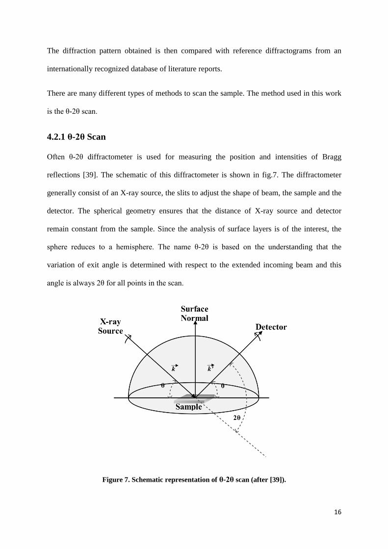
There are many different types of methods to scan the sample. The method used in this work
is the θ-2θ scan.
4.2.1 θ-2θ Scan
Often θ-2θ diffractometer is used for measuring the position and intensities of Bragg
reflections [39]. The schematic of this diffractometer is shown in fig.7. The diffractometer
generally consist of an X-ray source, the slits to adjust the shape of beam, the sample and the
detector. The spherical geometry ensures that the distance of X-ray source and detector
remain constant from the sample. Since the analysis of surface layers is of the interest, the
sphere reduces to a hemisphere. The name θ-2θ is based on the understanding that the
variation of exit angle is determined with respect to the extended incoming beam and this
angle is always 2θ for all points in the scan.
Figure 7. Schematic representation of θ-2θ scan (after [39]).
17
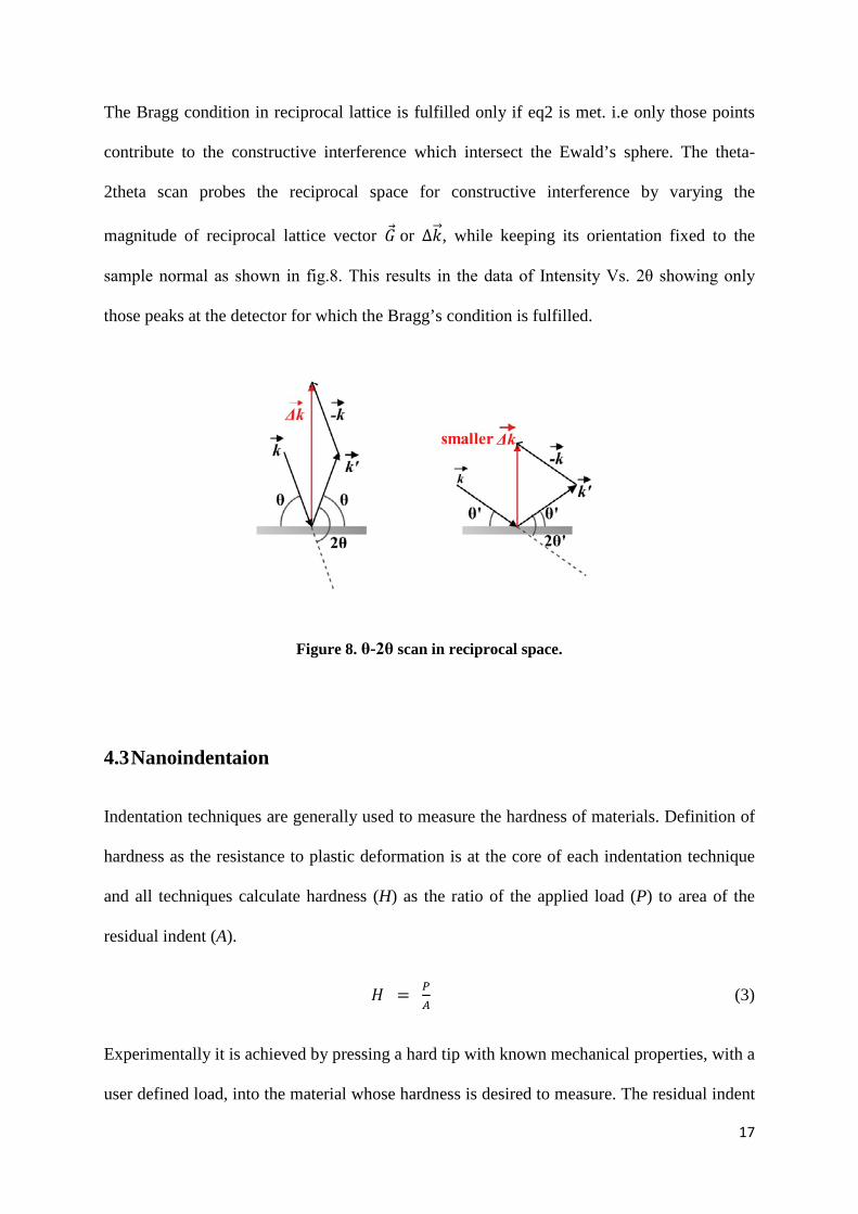
The Bragg condition in reciprocal lattice is fulfilled only if eq2 is met. i.e only those points
contribute to the constructive interference which intersect the Ewald’s sphere. The theta-
2theta scan probes the reciprocal space for constructive interference by varying the
magnitude of reciprocal lattice vector �⃗� or ∆𝑘�⃗ , while keeping its orientation fixed to the
sample normal as shown in fig.8. This results in the data of Intensity Vs. 2θ showing only
those peaks at the detector for which the Bragg’s condition is fulfilled.
Figure 8. θ-2θ scan in reciprocal space.
4.3 Nanoindentaion
Indentation techniques are generally used to measure the hardness of materials. Definition of
hardness as the resistance to plastic deformation is at the core of each indentation technique
and all techniques calculate hardness (H) as the ratio of the applied load (P) to area of the
residual indent (A).
𝐻 = 𝑃𝐴 (3)
Experimentally it is achieved by pressing a hard tip with known mechanical properties, with a
user defined load, into the material whose hardness is desired to measure. The residual indent
18
area (A) may then be calculated by for exapmle optical means which then is substituted in
eq.(3) along with the known load (P) to get the hardness (H).
In nanoindentation the load is in the milli-newton range that leaves the residual indent area of
the order of few square micrometers or nanometers. This makes the optical method to
measure residual area redundant. Thus instead of residual indent area, the area under the
contact is used. To measure the area under the contact, the indentation depth and the known
shape and the area of indenter are used.
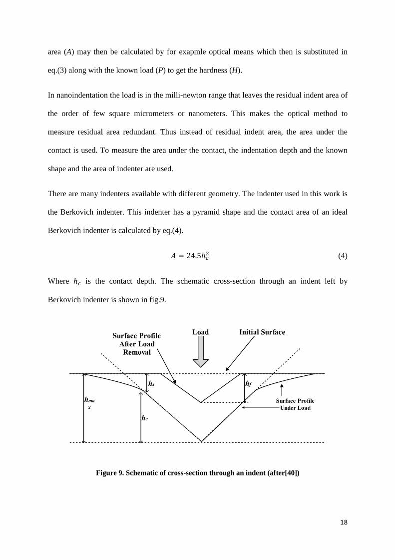
There are many indenters available with different geometry. The indenter used in this work is
the Berkovich indenter. This indenter has a pyramid shape and the contact area of an ideal
Berkovich indenter is calculated by eq.(4).
𝐴 = 24.5ℎ𝑐2 (4)
Where ℎ𝑐 is the contact depth. The schematic cross-section through an indent left by
Berkovich indenter is shown in fig.9.
Figure 9. Schematic of cross-section through an indent (after[40])
19
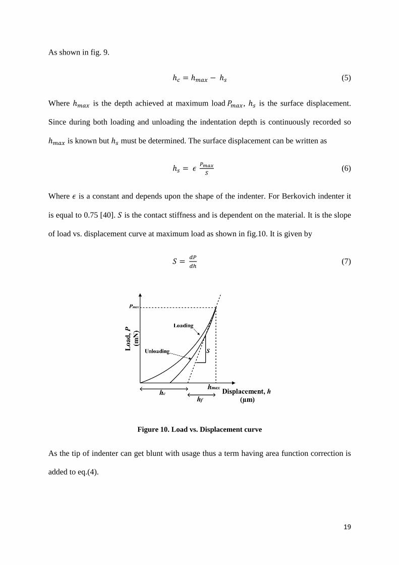
As shown in fig. 9.
ℎ𝑐 = ℎ𝑚𝑎𝑥 − ℎ𝑠 (5)
Where ℎ𝑚𝑎𝑥 is the depth achieved at maximum load 𝑃𝑚𝑎𝑥, ℎ𝑠 is the surface displacement.
Since during both loading and unloading the indentation depth is continuously recorded so
ℎ𝑚𝑎𝑥 is known but ℎ𝑠 must be determined. The surface displacement can be written as
ℎ𝑠 = 𝜖 𝑃𝑚𝑎𝑥𝑆
(6)
Where 𝜖 is a constant and depends upon the shape of the indenter. For Berkovich indenter it
is equal to 0.75 [40]. 𝑆 is the contact stiffness and is dependent on the material. It is the slope
of load vs. displacement curve at maximum load as shown in fig.10. It is given by
𝑆 = 𝑑𝑃𝑑ℎ
(7)
Figure 10. Load vs. Displacement curve
As the tip of indenter can get blunt with usage thus a term having area function correction is
added to eq.(4).

20
21
5. Experimental Details
Pre-depositon treatment of the substrates was performed by cleaning the WC-Co substrates in
ultrasonic baths of alkali solution and alcohol.
The substrates were then mounted onto the rotating drum fixture of an industrial
Sulzer/Metaplas MZR-323 reactive cathodic arc evaporation system equipped with
compound cathodes in an atmosphere of nitrogen. Three circular cathodes, each with a
diameter of 63mm, were mounted vertically in line with a separation of 15cm on one of the
cathode flanges of the deposition chamber. The compositions of the cathodes were Zr20Al80,
Cr33Al67, Cr50Al50 and Zr. The vertical placement as well as the difference in compositions of
the cathodes results in a varying deposition flux over the height of the drum fixture providing
a gradient in the compositions of the coatings depending upon the position of the substrates in
the line of sight of the cathodes. The WC-Co substrates were equidistantly positioned in 5
rows along the height of the drum fixture with the cathode to substrate distance of about
15cm.
The system was then evacuated to a pressure of less than 2.0x10⁻³ Pa. The substrates were
then sputter sputtered with Ar ions. The deposition was then carried out with a cathode
22
current of 60A in 4.5Pa of N2, a fixed substrate bias of -40V at about 500 οC while
maintaining the drum rotation of 3rpm for two hours resulting in a coating of ~3µm.
Post deposition isothermal annealing was carried out at the starting temperatures of 800, 900,
1000 and 1100 οC for two hours in an argon environment at an atmospheric pressure using
Sintervac furnace from GCA Vacuum Industries. The Samples were annealed with a rate of 7
oC/min till the temperature went down to 40 oC below the starting temperature. The rate was
then reduced to 5oC/min. The samples were eventually cooled to 500 oC in 1.5 hours and
further cooled to 100 oC in 4 hours.
Compositions of the coatings were established by EDX. This is done with Leo 1550 Gemini
scanning electron microscope which was operated at 20kV, maximum magnification and a
working distance of 8.5mm. The EDX was first calibrated with Cu reference sample. The
yielded compositions in this work ranged from (ZrxCryAlz)1N1 0.01<x<0.81, 0.09<y<0.54
and 0.10<z<0.72 (x+y+z = 1).
XRD was performed with X’ Pert PRO from PANalytical using Cu-Kα radiation. The scan
mode of θ-2θ was selected with 2θ ranging from 30ο to 50ο.
Hardness of the coatings was determined by nanoindentation. Nanoindentation was
performed with CISRO UMIS nanoindenter fitted with Berkovich diamond indenter. Fused
silica was used as a reference. The samples for nanoindentation were prepared by grinding
and polishing the cross section of coatings mounted in Bakelite. The samples were then
cleaned with acetone. An optimum load of 33mN was selected for which the penetration
depth was around 0.20µm, which is within 10% of the coating thickness [41]. On each
sample 40 indents were performed and then the average hardness was calculated
23
6. Results and Discussion
Based on the methods and techniques used, the results of thermal stability of ZrCrAlN
material system are presented here.
6.1 Compositions
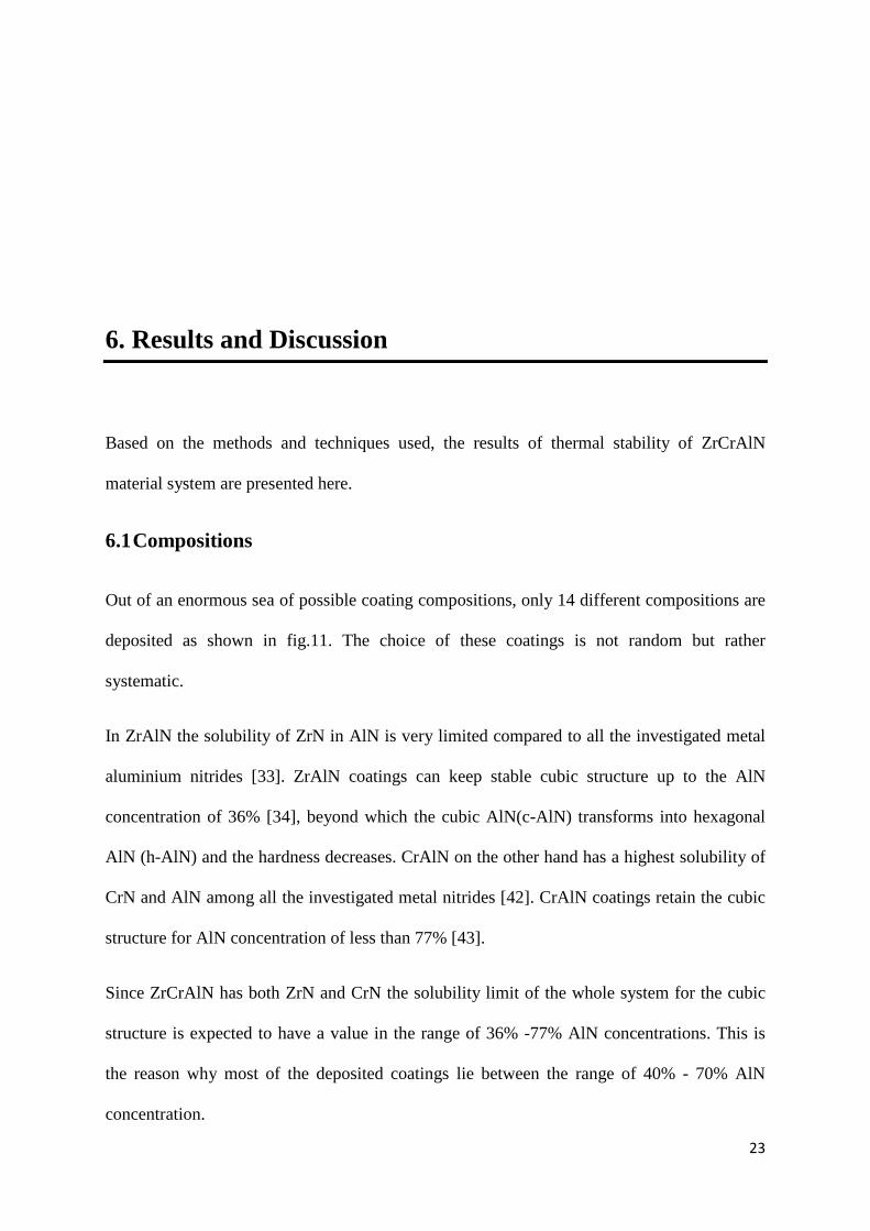
Out of an enormous sea of possible coating compositions, only 14 different compositions are
deposited as shown in fig.11. The choice of these coatings is not random but rather
systematic.
In ZrAlN the solubility of ZrN in AlN is very limited compared to all the investigated metal
aluminium nitrides [33]. ZrAlN coatings can keep stable cubic structure up to the AlN
concentration of 36% [34], beyond which the cubic AlN(c-AlN) transforms into hexagonal
AlN (h-AlN) and the hardness decreases. CrAlN on the other hand has a highest solubility of
CrN and AlN among all the investigated metal nitrides [42]. CrAlN coatings retain the cubic
structure for AlN concentration of less than 77% [43].
Since ZrCrAlN has both ZrN and CrN the solubility limit of the whole system for the cubic
structure is expected to have a value in the range of 36% -77% AlN concentrations. This is
the reason why most of the deposited coatings lie between the range of 40% - 70% AlN
concentration.
24
The deposited coatings can be broadly categorized with three different aluminium
compositions, namely 40%, 50% and 70%.
Figure 11. Deposited composions of ZrCrAlN system
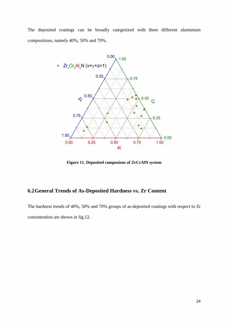
6.2 General Trends of As-Deposited Hardness vs. Zr Content
The hardness trends of 40%, 50% and 70% groups of as-deposited coatings with respect to Zr
concentration are shown in fig.12.
25
Figure 12. General Trends of As-Deposited Hardness vs Zr content.
6.2.1 40%Al
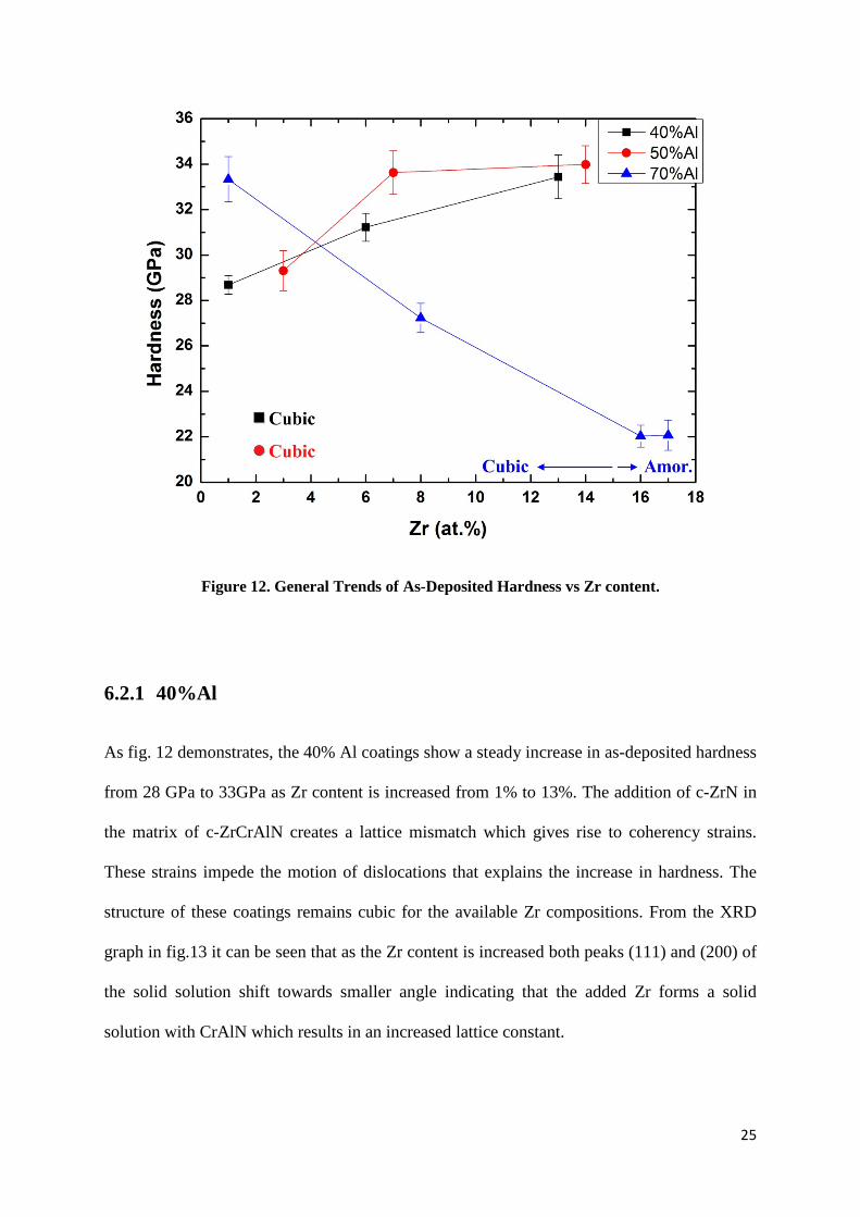
As fig. 12 demonstrates, the 40% Al coatings show a steady increase in as-deposited hardness
from 28 GPa to 33GPa as Zr content is increased from 1% to 13%. The addition of c-ZrN in
the matrix of c-ZrCrAlN creates a lattice mismatch which gives rise to coherency strains.
These strains impede the motion of dislocations that explains the increase in hardness. The
structure of these coatings remains cubic for the available Zr compositions. From the XRD
graph in fig.13 it can be seen that as the Zr content is increased both peaks (111) and (200) of
the solid solution shift towards smaller angle indicating that the added Zr forms a solid
solution with CrAlN which results in an increased lattice constant.
26
For this category, the as-deposited hardness curve displays an increasing trend all the way to
the solubility of 13% Zr. The ascending hardness curve suggests that the cubic structure will
be stable beyond 13% Zr until the solubility limit of Zr is reached. In light of this, it can be
explained that coatings with comparatively low Al content (40%) can accommodate
considerably high Zr content (≥ 13%) while keeping the cubic structure intact.
Figure 13.XRD Graph of 40%Al category
2Ɵ
27
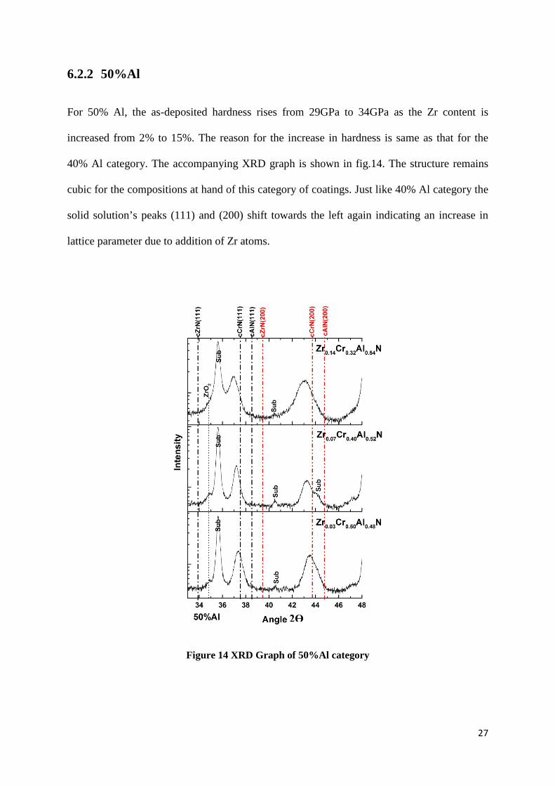
6.2.2 50%Al
For 50% Al, the as-deposited hardness rises from 29GPa to 34GPa as the Zr content is
increased from 2% to 15%. The reason for the increase in hardness is same as that for the
40% Al category. The accompanying XRD graph is shown in fig.14. The structure remains
cubic for the compositions at hand of this category of coatings. Just like 40% Al category the
solid solution’s peaks (111) and (200) shift towards the left again indicating an increase in
lattice parameter due to addition of Zr atoms.
Figure 14 XRD Graph of 50%Al category
2Ɵ
28
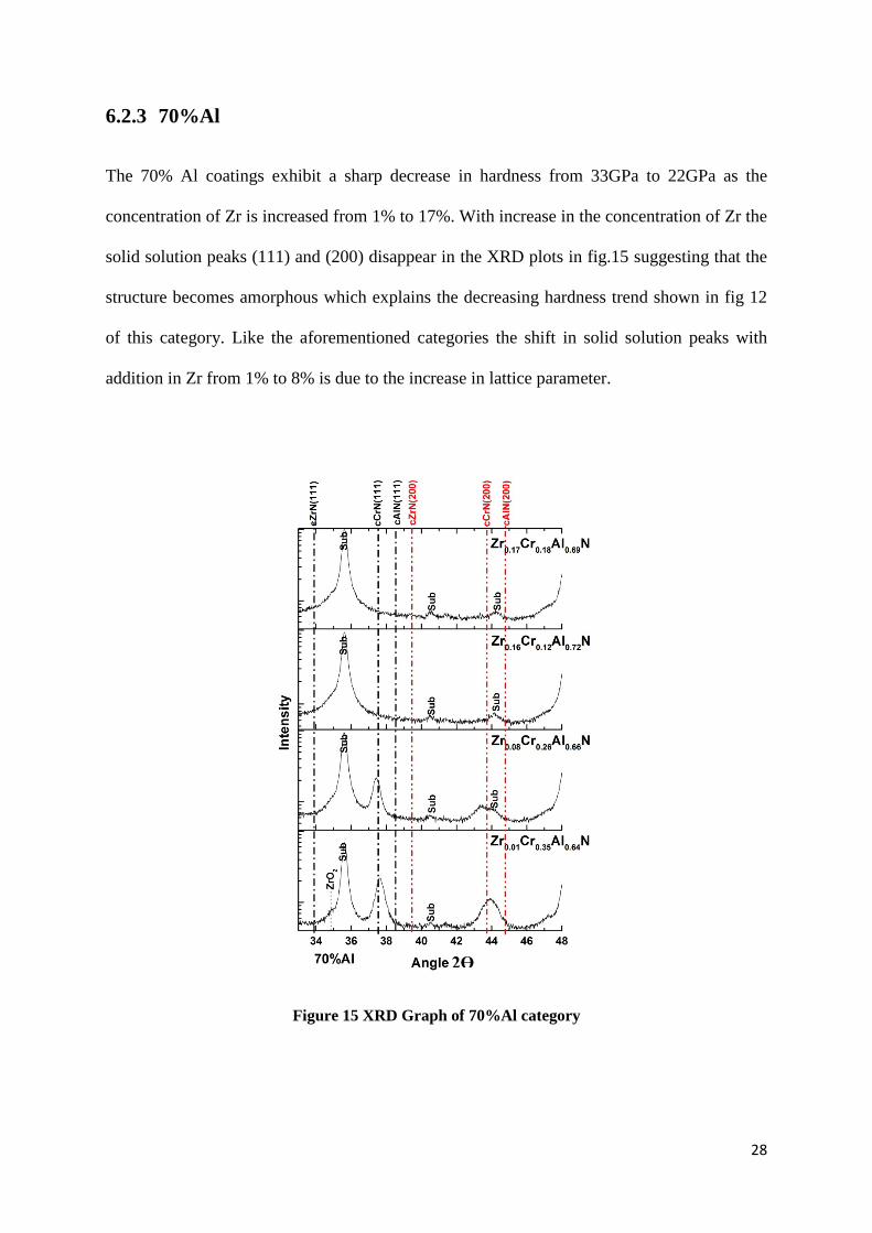
6.2.3 70%Al
The 70% Al coatings exhibit a sharp decrease in hardness from 33GPa to 22GPa as the
concentration of Zr is increased from 1% to 17%. With increase in the concentration of Zr the
solid solution peaks (111) and (200) disappear in the XRD plots in fig.15 suggesting that the
structure becomes amorphous which explains the decreasing hardness trend shown in fig 12
of this category. Like the aforementioned categories the shift in solid solution peaks with
addition in Zr from 1% to 8% is due to the increase in lattice parameter.
Figure 15 XRD Graph of 70%Al category
2Ɵ
29
Compared to 40% and 50% categories the solid solution peaks for the lowest Zr content is
more towards AlN, which justifies a higher Al content. In all the above mentioned categories
the XRD graphs show ZrO2 peak at an angle of 34.8o.
6.3 Thermal Stability
Thermal stability of ZrCrAlN system is discussed in comparison with ZrAlN and CrAlN
systems.
6.3.1 ZrAlN
The hardness values of two samples belonging to 70% Al category annealed at different
temperatures are plotted with the documented Zr0.44Al0.56N coating [2] in fig.16. The post
deposition annealing of Zr0.44Al0.56N is shown to result in significant age hardening with a
hardness increase of 36%[2]. Zr0.17Cr0.16Al0.67N and Zr0.16Cr0.12Al0.72N demonstrate similar
trends of age hardening. The age hardening in the case of Zr0.16Cr0.12Al0.72N is found to be
33% which is a significant increase in hardness among the multinary coatings.
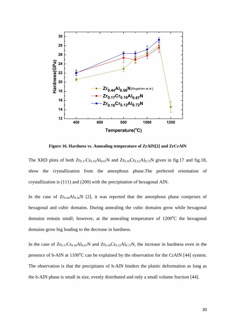
30
Figure 16. Hardness vs. Annealing temperature of ZrAlN[2] and ZrCrAlN
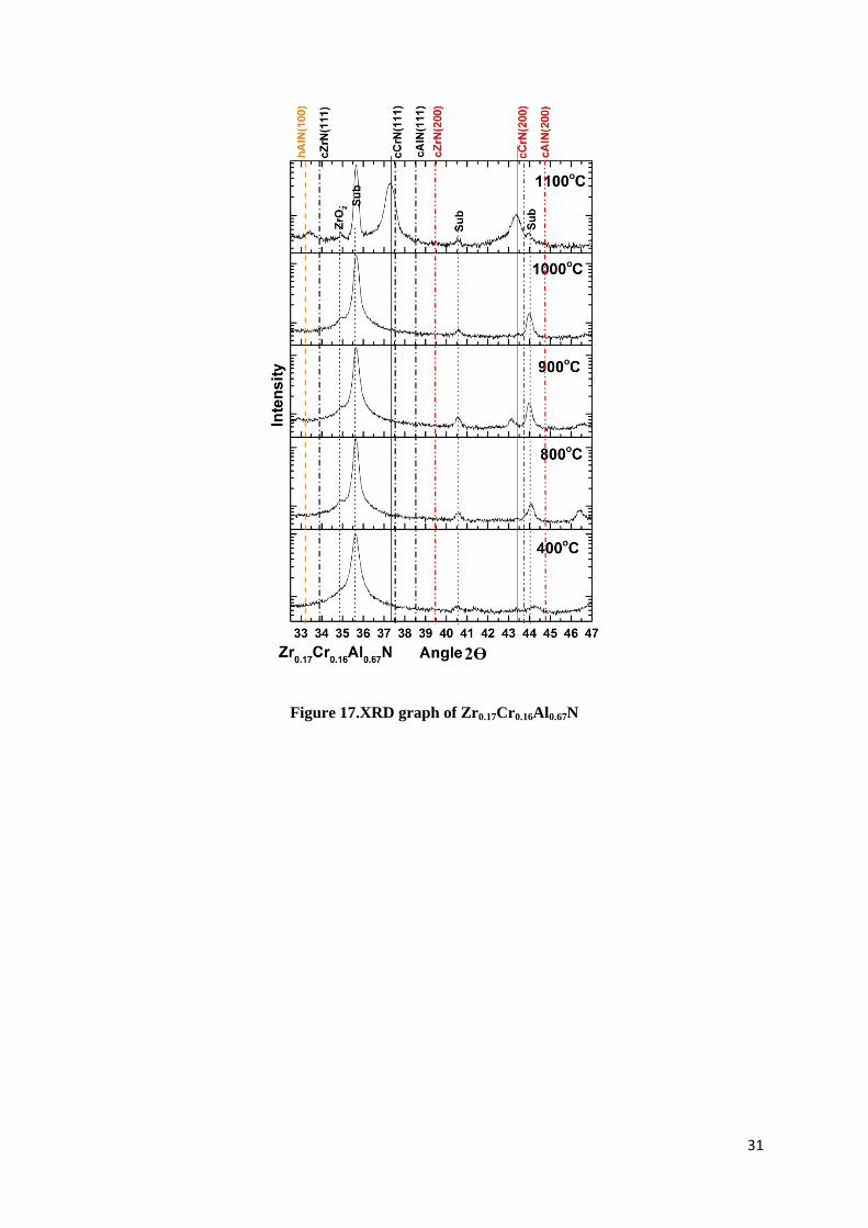
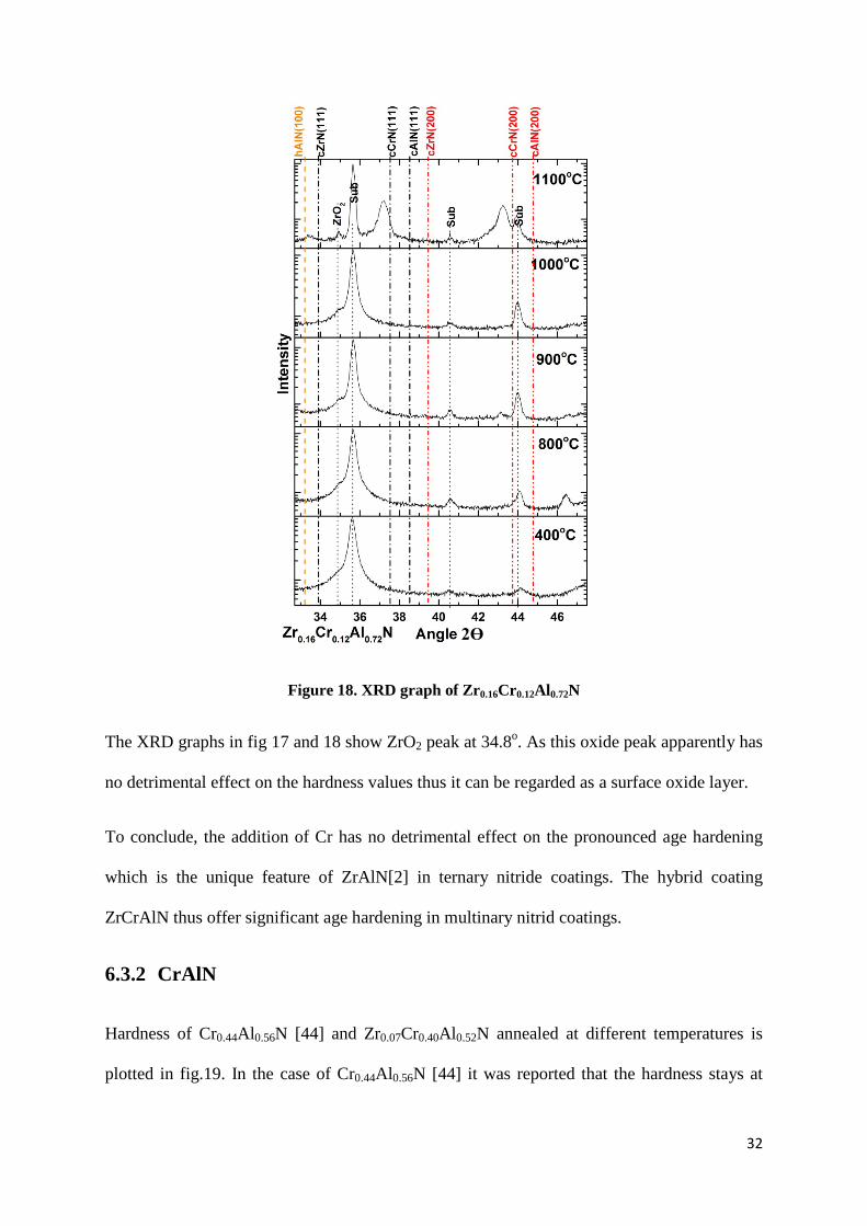
The XRD plots of both Zr0.17Cr0.16Al0.67N and Zr0.16Cr0.12Al0.72N given in fig.17 and fig.18,
show the crystallization from the amorphous phase.The preferred orientation of
crystallization is (111) and (200) with the precipitation of hexagonal AlN.
In the case of Zr0.44Al0.56N [2], it was reported that the amorphous phase comprises of
hexagonal and cubic domains. During annealing the cubic domains grow while hexagonal
domains remain small; however, at the annealing temperature of 1200oC the hexagonal
domains grow big leading to the decrease in hardness.
In the case of Zr0.17Cr0.16Al0.67N and Zr0.16Cr0.12Al0.72N, the increase in hardness even in the
presence of h-AlN at 1100oC can be explained by the observation for the CrAlN [44] system.
The observation is that the precipitates of h-AlN hinders the plastic deformation as long as
the h-AlN phase is small in size, evenly distributed and only a small volume fraction [44].
31
Figure 17.XRD graph of Zr0.17Cr0.16Al0.67N
2Ɵ
32
Figure 18. XRD graph of Zr0.16Cr0.12Al0.72N
The XRD graphs in fig 17 and 18 show ZrO2 peak at 34.8o. As this oxide peak apparently has
no detrimental effect on the hardness values thus it can be regarded as a surface oxide layer.
To conclude, the addition of Cr has no detrimental effect on the pronounced age hardening
which is the unique feature of ZrAlN[2] in ternary nitride coatings. The hybrid coating
ZrCrAlN thus offer significant age hardening in multinary nitrid coatings.
6.3.2 CrAlN
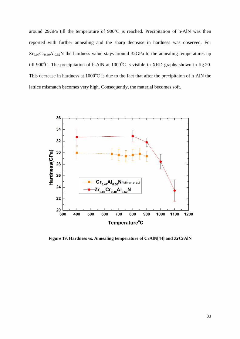
Hardness of Cr0.44Al0.56N [44] and Zr0.07Cr0.40Al0.52N annealed at different temperatures is
plotted in fig.19. In the case of Cr0.44Al0.56N [44] it was reported that the hardness stays at
2Ɵ
33
around 29GPa till the temperature of 900oC is reached. Precipitation of h-AlN was then
reported with further annealing and the sharp decrease in hardness was observed. For
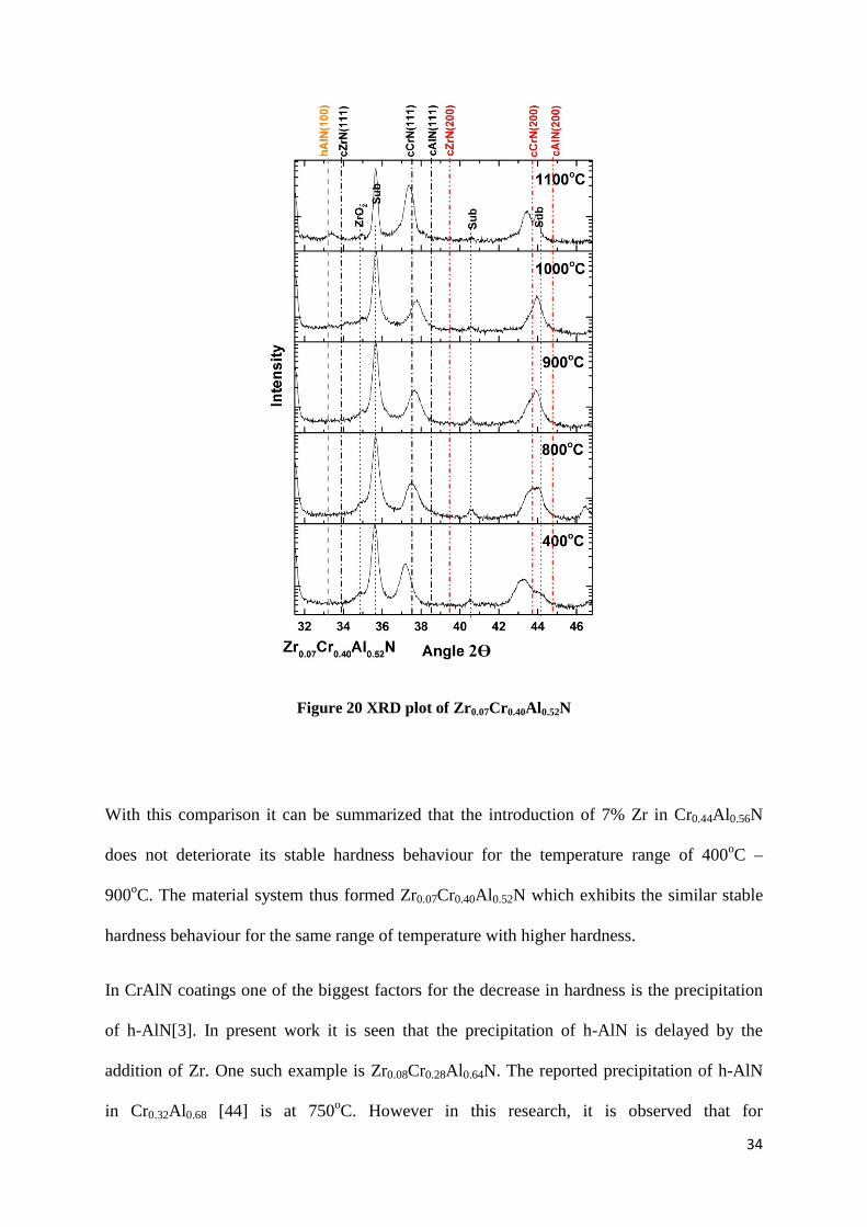
Zr0.07Cr0.40Al0.52N the hardness value stays around 32GPa to the annealing temperatures up
till 900oC. The precipitation of h-AlN at 1000oC is visible in XRD graphs shown in fig.20.
This decrease in hardness at 1000oC is due to the fact that after the precipitaion of h-AlN the
lattice mismatch becomes very high. Consequently, the material becomes soft.
Figure 19. Hardness vs. Annealing temperature of CrAlN[44] and ZrCrAlN
34
Figure 20 XRD plot of Zr0.07Cr0.40Al0.52N
With this comparison it can be summarized that the introduction of 7% Zr in Cr0.44Al0.56N
does not deteriorate its stable hardness behaviour for the temperature range of 400oC –
900oC. The material system thus formed Zr0.07Cr0.40Al0.52N which exhibits the similar stable
hardness behaviour for the same range of temperature with higher hardness.
In CrAlN coatings one of the biggest factors for the decrease in hardness is the precipitation
of h-AlN[3]. In present work it is seen that the precipitation of h-AlN is delayed by the
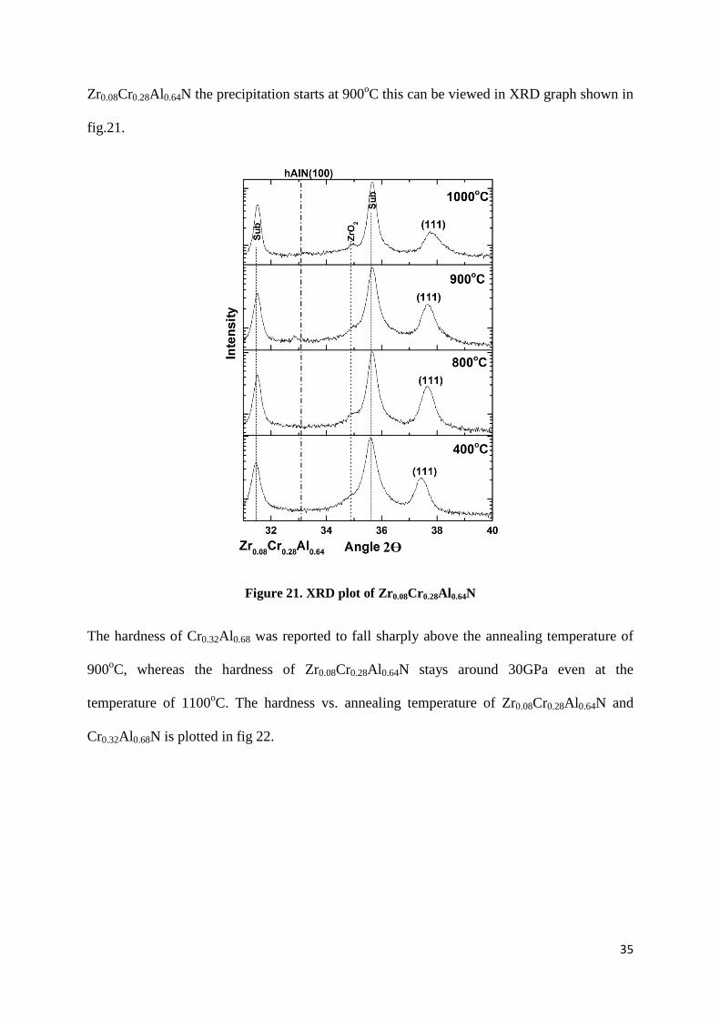
addition of Zr. One such example is Zr0.08Cr0.28Al0.64N. The reported precipitation of h-AlN
in Cr0.32Al0.68 [44] is at 750oC. However in this research, it is observed that for
2Ɵ
35
Zr0.08Cr0.28Al0.64N the precipitation starts at 900oC this can be viewed in XRD graph shown in
fig.21.
Figure 21. XRD plot of Zr0.08Cr0.28Al0.64N
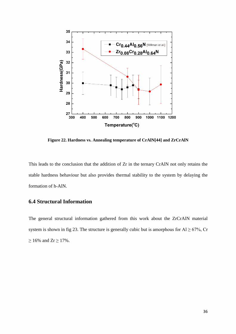
The hardness of Cr0.32Al0.68 was reported to fall sharply above the annealing temperature of
900oC, whereas the hardness of Zr0.08Cr0.28Al0.64N stays around 30GPa even at the
temperature of 1100oC. The hardness vs. annealing temperature of Zr0.08Cr0.28Al0.64N and
Cr0.32Al0.68N is plotted in fig 22.
2Ɵ
36
Figure 22. Hardness vs. Annealing temperature of CrAlN[44] and ZrCrAlN
This leads to the conclusion that the addition of Zr in the ternary CrAlN not only retains the
stable hardness behaviour but also provides thermal stability to the system by delaying the
formation of h-AlN.
6.4 Structural Information
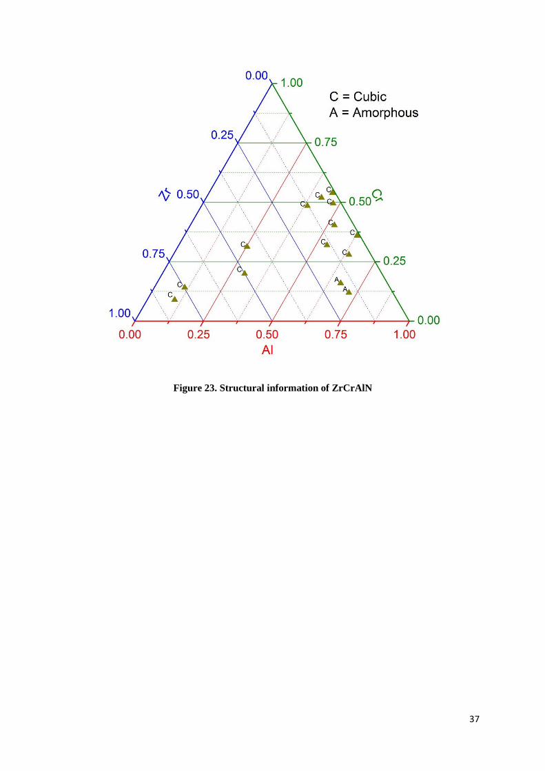
The general structural information gathered from this work about the ZrCrAlN material
system is shown in fig 23. The structure is generally cubic but is amorphous for Al ≥ 67%, Cr
≥ 16% and Zr ≥ 17%.
37
Figure 23. Structural information of ZrCrAlN

38
39
7. Conclusion
Significant age hardening and delayed formation of h-AlN proved that ZrCrAlN has shown
good thermal stability. This warrants the need to explore this system further.

40
41
8. Future Outlook
Thermal stability shown by ZrCrAlN provides the motivation to explore this system further.
Magnetron sputtering system will give a precise control over the coatings compositions
which will be beneficial for the further exploration.
Transmission Electron microscopy and X-ray photoelectron spectroscopy can augment the
results from structural character characterization in this thesis work.
Studies in Multilayers of different material systems have proved better thermal stability.
Multilayers of this material system with other systems will be an interesting study.

42
43
9. References
[1] A. Hörling, L. Hultman, M. Odén, J. Sjolen, L. Karlsson, Surf. Coat. Technol. 384(2005)
191.
[2] L. Rogström, L.J.S. Johnson, M.P. Johansson, M. Ahlgren, L. Hultman, M. Odén,
Scri.Mater. 62(2010) 739-741.
[3] H. Willmann, P.H. Mayrhofer, P.O.Å. Persson, A.E. Reiter, L. Hultman, C. Mitterer,
Scri.Mater. 54(2006) 1848-1851.
[4] A.E. Reiter, C. Mitterer, B. Sartory, J. Vac. Sci. Technol. A. 25(4), 711–720(2007)
[5] H. Lind, R. Forsén, B. Alling, N. Ghafoor, F. Tasnádi, M.P. Johansson, I.A. Abrikosov,
M. Odén, Appl. Phys. Lett. 99 091903 (2011).
[6] http://www.hardmaterials.sandvik.com/ 15-07-2012.
[7] Modern Metal Cutting : A Practical Handbook. ISBN 91-97 22 99-3-0. 1996 Sandvik
Coromant, N.J.
[8] I.Y. Konyashin, Surf. Coat. Technol. 71(1995) 277-283
[9] André Anders Cathodic Arcs, Springer Science (2008) ISBN 978-0-387-79107-4.
44
[10] I.G. Brown, Annl. Rev. Mat. Sci. Vol.28, (1998) 243-269
[11] Donald M. Mattox, Metal Finishing. 100(2002) 394-408.
[12] J.E. Sundgren, Thin Solid Films. 128(1985) 21.
[13] H. Ichimur, A. Kawana J. Mat. Res. 8 5(1993) 1093.
[14] O. Knotek, W.-D. Münz, T. Leyendecker, J. Vac. Sci. Technol. A. 5(4) (1987) 2173.
[15] A.E. Reiter, V.H. Derflinger, B. Hanselmann, T. Bachmann, B. Sartory, Surf. Coat.
Technol. 200(2005) 2114.
[16] H. Spillmann, P.R. Willmott, M. Morstein, P.J. Uggowitzer, Appl. Phys. A. 73 (2011)
441.
[17] C. Höglund, J. Bareño, J. Birch, B. Alling, Z. Czigány, L. Hultman, J. Appl. Phys.
105(2009) 113517.
[18] B. Howe, J. Bareño, M. Sardela, J.G. Wen, J. E. Greene, L. Hultman, A.A. Veoevodin, I.
Petrov, Surf. Coat. Technol. 202 (2007) 809.
[19] Y.C. Chim, X.Z. Ding, X.T. Zeng, S. Zhang, Thin Solid Films. 517 (2009) 4845–4849.
[20] B. Alling, T. Marten, I.A. Abrikosov, A. Karimi, J. Appl. Phys. 102 (4) (2007).
[21] c-ZrN. Pdf No. 35-0753, JCPDS – ICDD, 1998.
[22] K. A. Gruss, T. Zheleva, R.F. Davis, T.R. Watkins, Surf. Coat. Technol. 107(1998) 115.
[23] E. W. Niu, L. Li, G.H. Lv, H. Chen, W.R. Feng, S.H. Fan, S.Z. Yang, X.Z. Yang, Mater.
Sci. Eng. A. 460-461 (2007) 135.
45
[24] J. Musil, I. Stepanek, M. Kolego, O. Blahova, J. Byskocil, J. Kasl, Mater. Sci. Eng. A.
163 (1993) 211.
[25] I. Milosev, H.H. Strehblow, B. Navinsek, Thin Solid Films. 303 (1997) 246.
[26] c-CrN, Pdf No. 11-0065, JCPDS – ICDD, 1998.
[27] G.G. Fuentes, R. Rodriguez, .C. Avelar-Batista, J. Housden, F. Montalá, L.J. Carreras,
A.B. Cristóbal, J.J. Damborenea, T.J. Tate, J. Mat. Process. Technol. 167 (2005) 415–421.
[28] h-CrN. Pdf No. 35-0803, JCPDS – ICDD, 1998.
[29] H. Chen, P.Q. Wu, C. Quaeyhaegens, K.W. Xu, L.M. Stals, J.W. He, J.-P. Celis, Wear.
253 (2002) 527–532.
[30] M. Oden, J. Almer, G. Håkansson, M. Olsson, Thin Solid Films. 377- 378(2000) 407-
412.
[31] h-AlN. Pdf. No. 00-003-1144, JCPDS – ICDD, 1998.
[32] c-AlN. Pdf. No. 46-1200, JCPDS – ICDD, 1998.
[33] ] B. Alling, A. Karimi, I.A. Abrikosov, Surf. Coat. Technol. 203 (2008) 883.
[34] L. Rogström, M.P. Johansson, N. Ghafoor, L. Hultman, M. Odén, J. Vac. Sci. Technol.
A. 30 3 (2012) 031504-031504.
[35] Y. Makino, K. Nogi, Surf. Coat. Technol. 98 (1998) 1008.
[36] P.H. Mayrhofer, H. Willmann, A .E. Reiter, Surf. Coat. Technol. 202 (2008) 49 35–4
938
46
[37] A.E. Reiter, V.H. Derflinger, B. Hanselmann, T. Bachmann, B. Sartory, Surf. Coat.
Technol. 200 (2005) 2114 – 2122.
[38] Z. Cai, P. Zhang, Y. Di, Adv. Mater. Res. 168-170 (2011) 2430-2433.
[39] M. Birkholz, Thin Film Analysis by X-ray Scattering, Wiley-VCH (2006), ISBN 3-527-
31052-5.
[40] W. C. Oliver and G. M. Pharr, J. Mater. Res .7 (6), (1992) 1564–1583
[41] A.C. Fischer-Cripps, Surf. Coat. Technol. 200(2006) 4153-4165.
[42] A. Sugishima, H. Kajioka, Y. Makino, Surf. Coat. Technol., 97(1-3) 590-594, 1997.
[43] Y. Makino, K. Nogi, Surf. Coat. Technol., 98(1-3), 1008-1012, 1998.
[44] H. Willmann, P.H. Mayrhofer, L. Hultman, C. Mitterer, J. Mater. Res.,23 (2008) 11.

47