Embed Size (px)
Citation preview
Thermoacoustic instabilities
Prof Aimee S. Morgans Department of Mechanical
Engineering
Combustion SIG Meeting September 28th 2017
Acoustic excitation of flames • Acoustic waves cause flame unsteadiness
Movie by Daniel Durox, EM2C Lab, Centrale Supelec, Paris
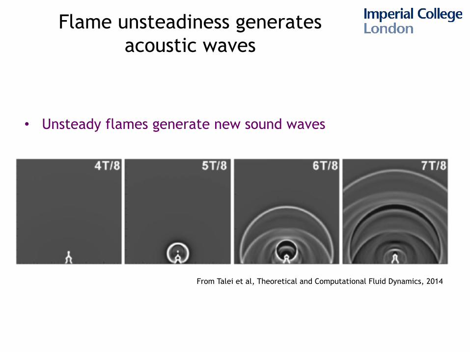
Flame unsteadiness generates acoustic waves
• Unsteady flames generate new sound waves
From Talei et al, Theoretical and Computational Fluid Dynamics, 2014
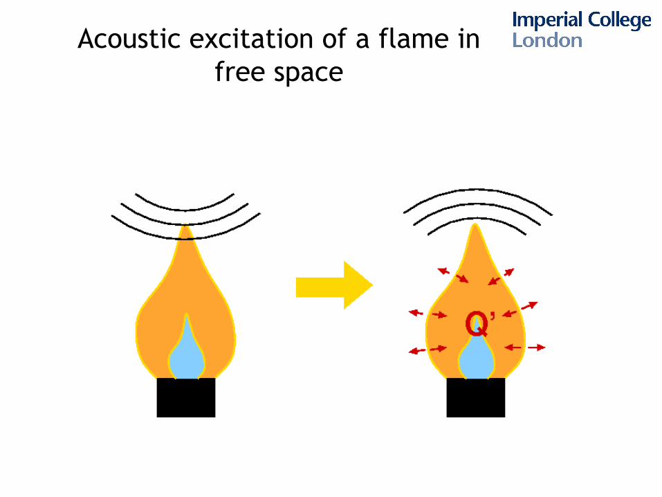
Acoustic excitation of a flame in free space
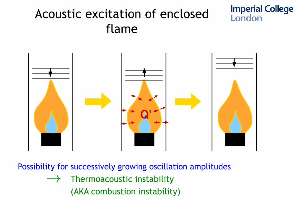
Acoustic excitation of enclosed flame
Possibility for successively growing oscillation amplitudes
Thermoacoustic instability (AKA combustion instability)
Thermoacoustic instability in a Rijke tube
Quartz tube, open at both ends with a Bunsen flame inside
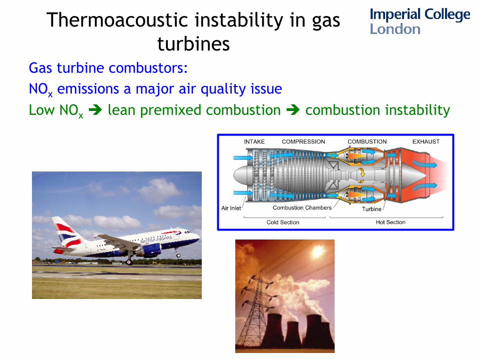
Thermoacoustic instability in gas turbines
Gas turbine combustors: NOx emissions a major air quality issue Low NOx è lean premixed combustion è combustion instability
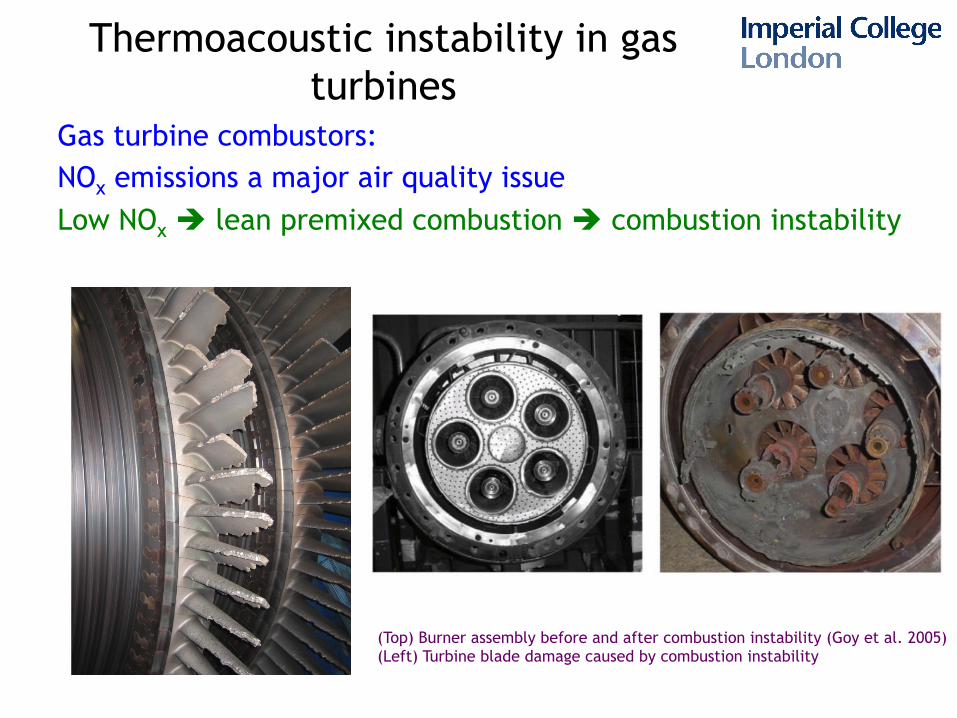
Thermoacoustic instability in gas turbines
Gas turbine combustors: NOx emissions a major air quality issue Low NOx è lean premixed combustion è combustion instability
(Top) Burner assembly before and after combustion instability (Goy et al. 2005) (Left) Turbine blade damage caused by combustion instability
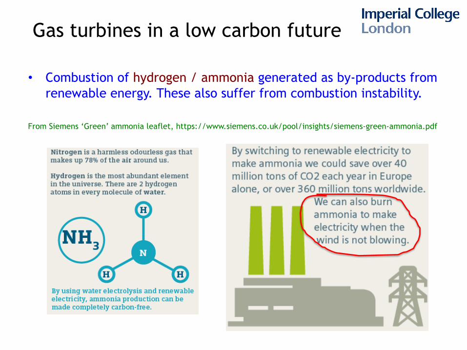
Gas turbines in a low carbon future
• Combustion of hydrogen / ammonia generated as by-products from renewable energy. These also suffer from combustion instability.
From Siemens ‘Green’ ammonia leaflet, https://www.siemens.co.uk/pool/insights/siemens-green-ammonia.pdf
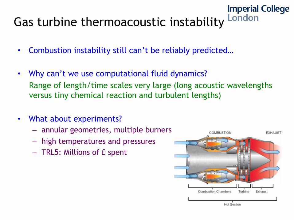
Gas turbine thermoacoustic instability
• Combustion instability still can’t be reliably predicted… • Why can’t we use computational fluid dynamics?
Range of length/time scales very large (long acoustic wavelengths versus tiny chemical reaction and turbulent lengths)
• What about experiments? – annular geometries, multiple burners – high temperatures and pressures – TRL5: Millions of £ spent
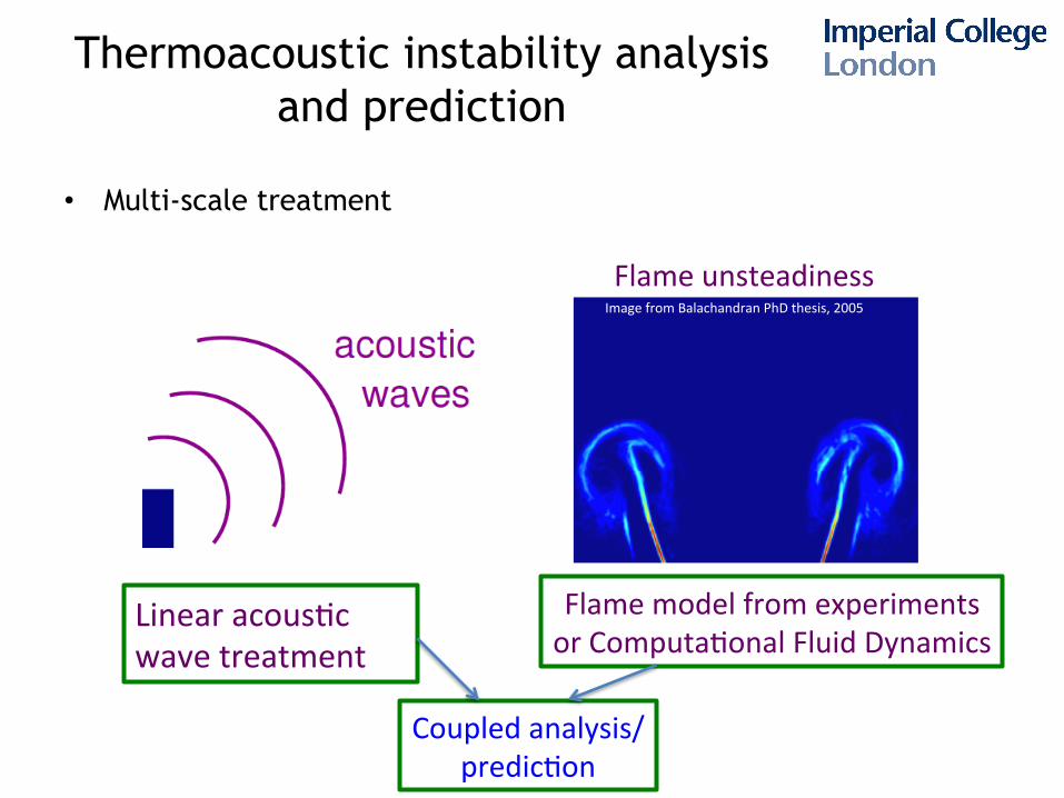
Thermoacoustic instability analysis and prediction
• Multi-scale treatment
Linear acous,c wave treatment
Flame model from experiments or Computa,onal Fluid Dynamics
Flame unsteadiness
Coupled analysis/predic,on
Image from Balachandran PhD thesis, 2005
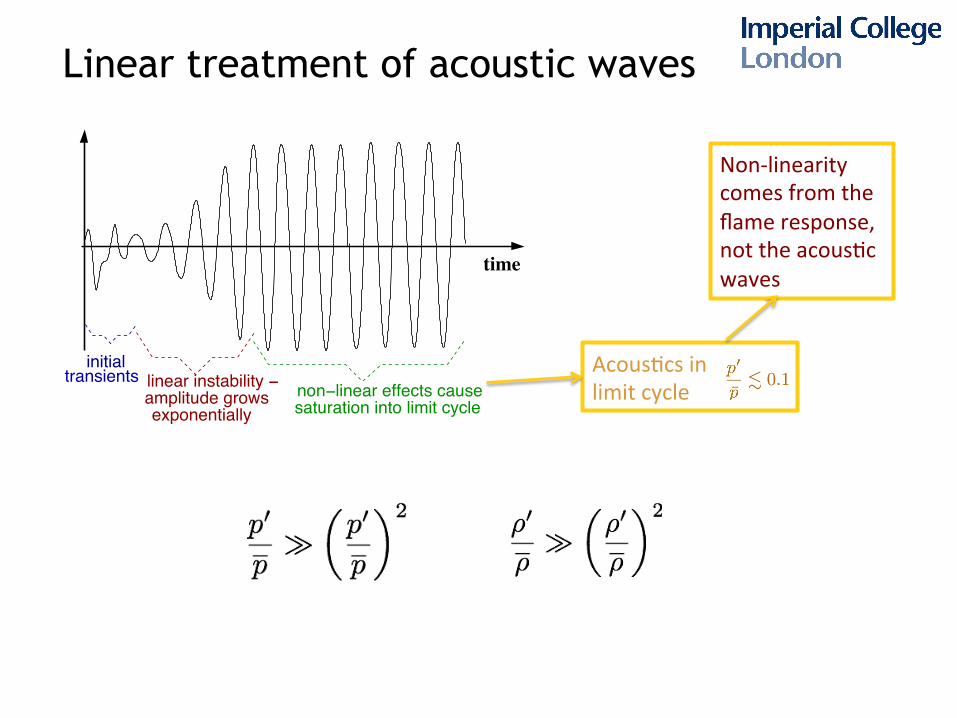
Linear treatment of acoustic waves
time
transientsinitial
non−linear effects causesaturation into limit cycle
linear instability − amplitude growsexponentially
Acous,cs in limit cycle
Non-‐linearity comes from the flame response, not the acous,c waves
Linear treatment of acoustic waves
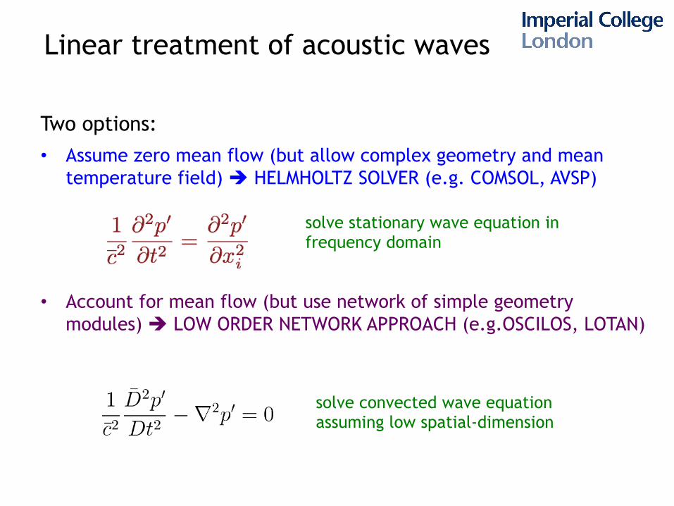
Two options: • Assume zero mean flow (but allow complex geometry and mean
temperature field) è HELMHOLTZ SOLVER (e.g. COMSOL, AVSP)
• Account for mean flow (but use network of simple geometry modules) è LOW ORDER NETWORK APPROACH (e.g.OSCILOS, LOTAN)
solve stationary wave equation in frequency domain
solve convected wave equation assuming low spatial-dimension
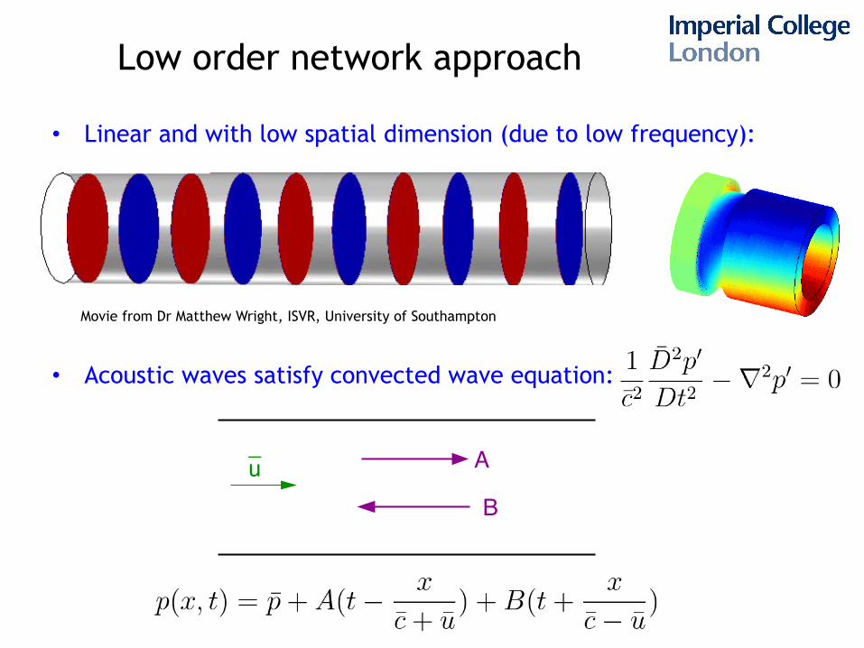
Low order network approach • Linear and with low spatial dimension (due to low frequency):
• Acoustic waves satisfy convected wave equation:
Movie from Dr Matthew Wright, ISVR, University of Southampton
_ A
Bu
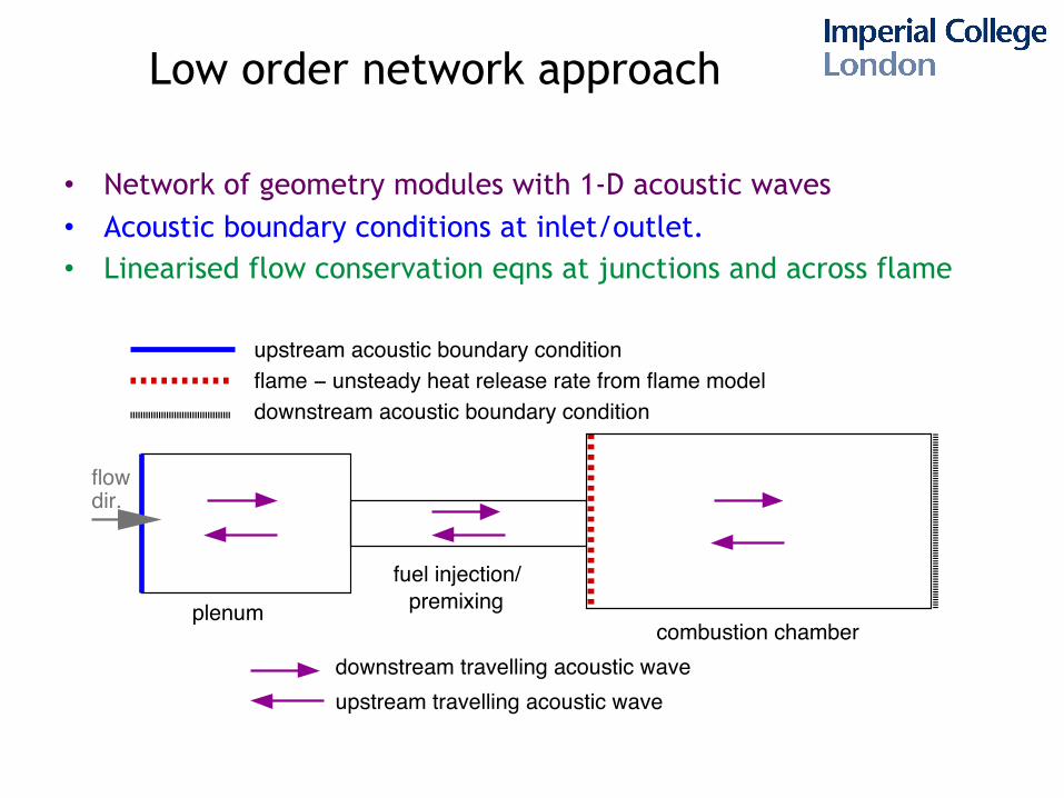
Low order network approach
• Network of geometry modules with 1-D acoustic waves • Acoustic boundary conditions at inlet/outlet. • Linearised flow conservation eqns at junctions and across flame
Figure 2. Low order network representation: example simplified geometry and acoustic waves
plenum premixingcombustion chamber
fuel injection/
flame − unsteady heat release rate from flame modeldownstream acoustic boundary condition
upstream acoustic boundary condition
downstream travelling acoustic waveupstream travelling acoustic wave
flowdir.
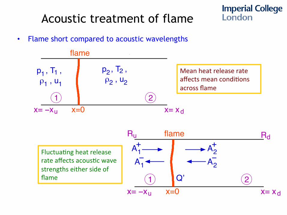
Acoustic treatment of flame
• Flame short compared to acoustic wavelengths
1ρ 1p , T ,
, u1
1
flame
1 2
ρ , u2p , T , 2
2 2
x=0x= −x x= xdu
dflame
1 2x=0x= −x x= xdu
AA− −
A+1
+2
2
Q’
A1
RuR
Mean heat release rate affects mean condi,ons across flame
Fluctua,ng heat release rate affects acous,c wave strengths either side of flame
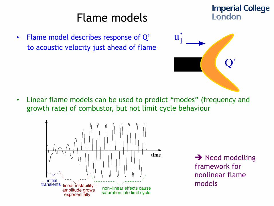
Flame models
• Flame model describes response of Q’ to acoustic velocity just ahead of flame
• Linear flame models can be used to predict “modes” (frequency and
growth rate) of combustor, but not limit cycle behaviour
u’1
Q’
time
transientsinitial
non−linear effects causesaturation into limit cycle
linear instability − amplitude growsexponentially
è Need modelling framework for nonlinear flame models
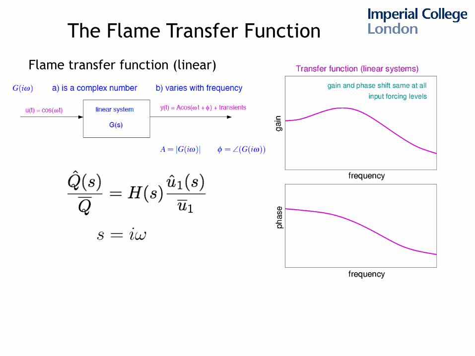
The Flame Transfer Function
Flame transfer function (linear)
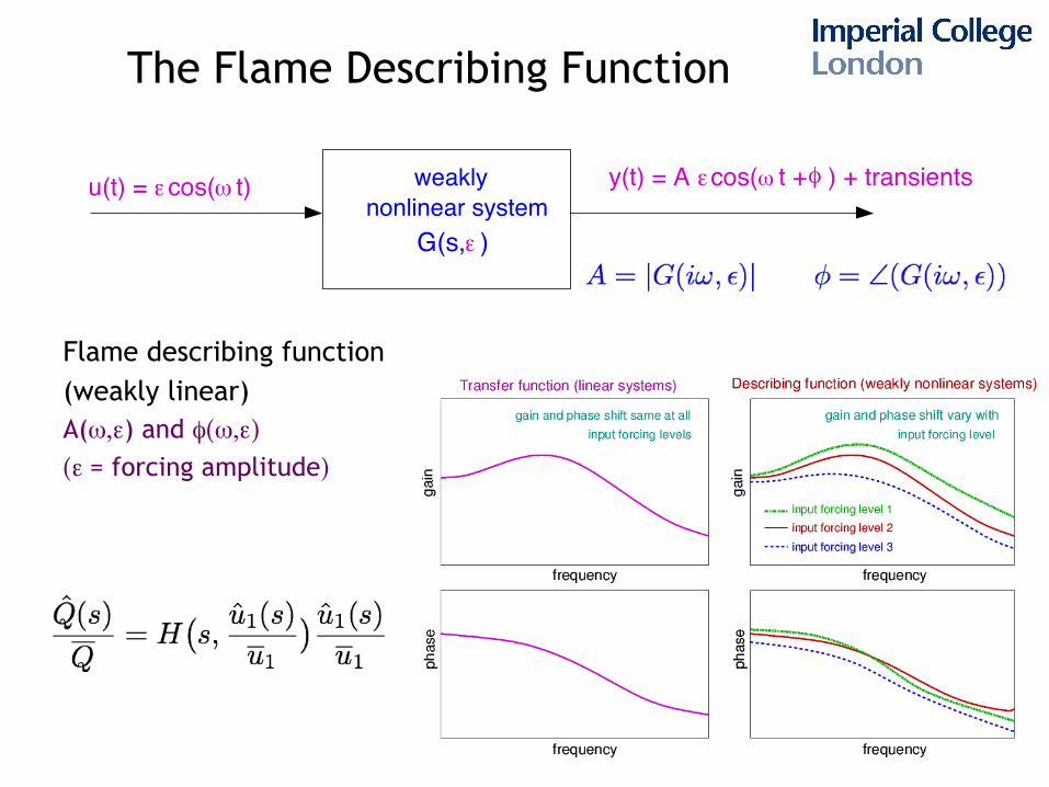
The Flame Describing Function
Flame describing function (weakly linear) A(ω,ε) and φ(ω,ε)
(ε = forcing amplitude)
φωεnonlinear system
u(t) = cos( t) ε
ε
weakly
G(s, )
ωy(t) = A cos( t + ) + transients
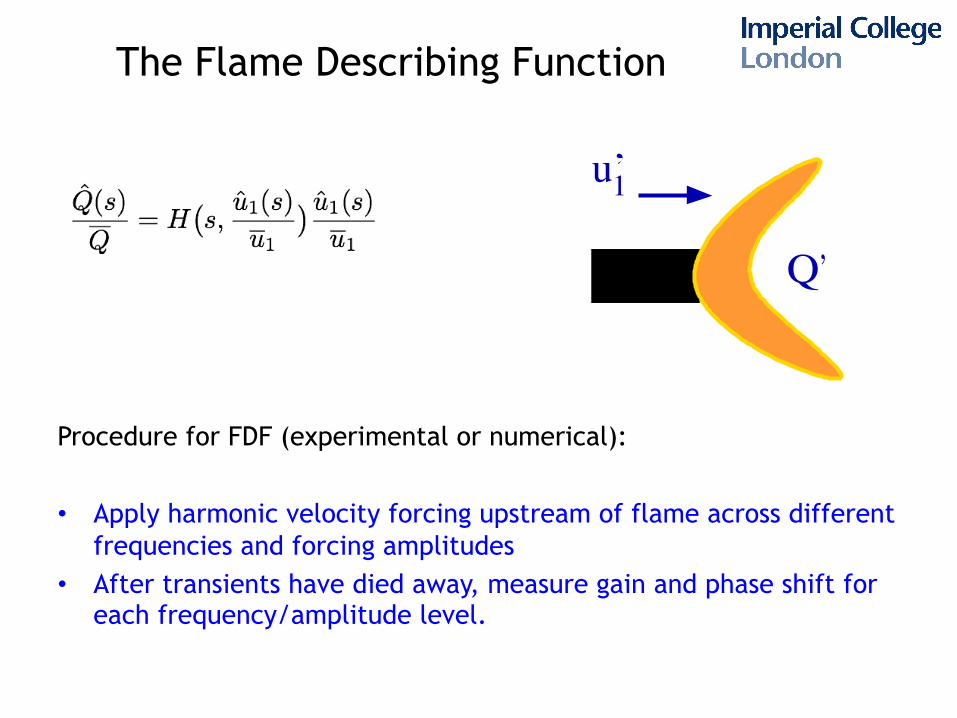
The Flame Describing Function
Procedure for FDF (experimental or numerical): • Apply harmonic velocity forcing upstream of flame across different
frequencies and forcing amplitudes • After transients have died away, measure gain and phase shift for
each frequency/amplitude level.
u’1
Q’
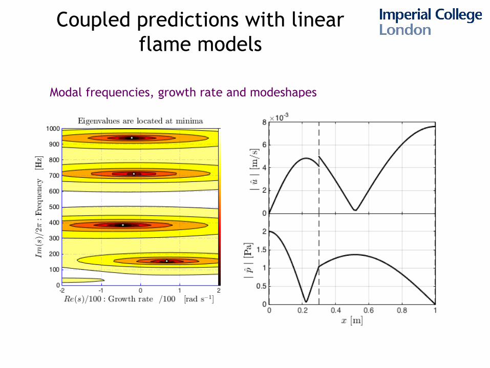
Coupled predictions with linear flame models
Modal frequencies, growth rate and modeshapes
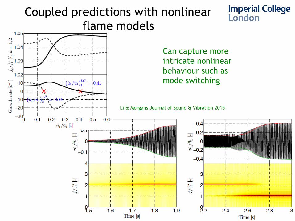
Coupled predictions with nonlinear flame models
Li & Morgans Journal of Sound & Vibration 2015
Can capture more intricate nonlinear behaviour such as mode switching
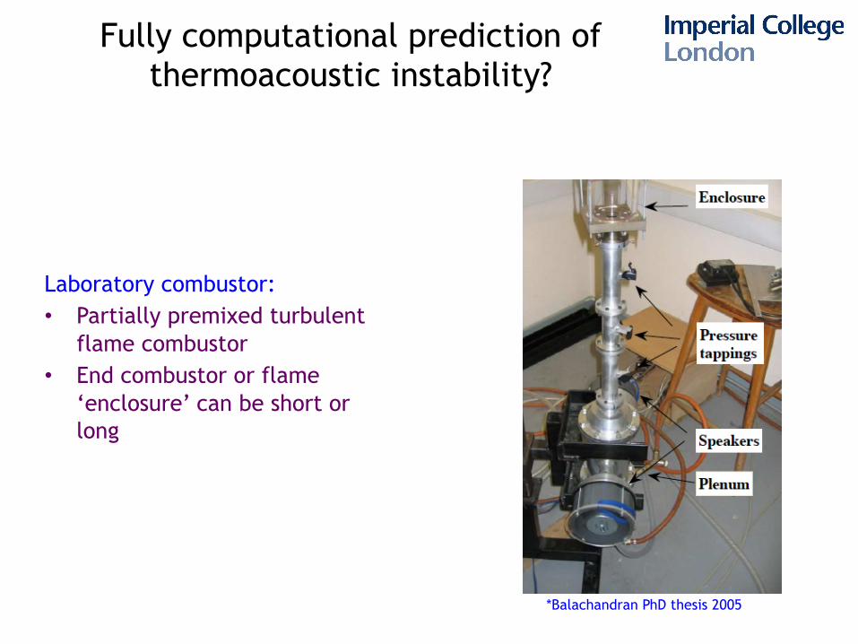
Fully computational prediction of thermoacoustic instability?
*Balachandran PhD thesis 2005
Laboratory combustor: • Partially premixed turbulent
flame combustor • End combustor or flame
‘enclosure’ can be short or long
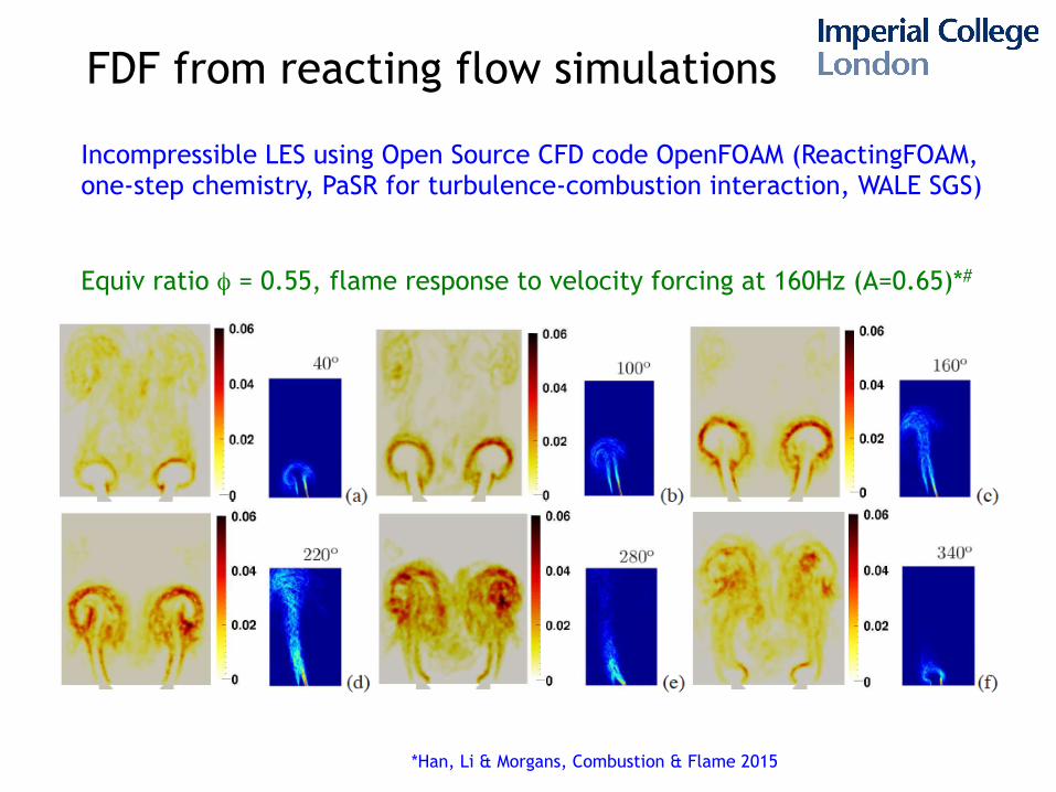
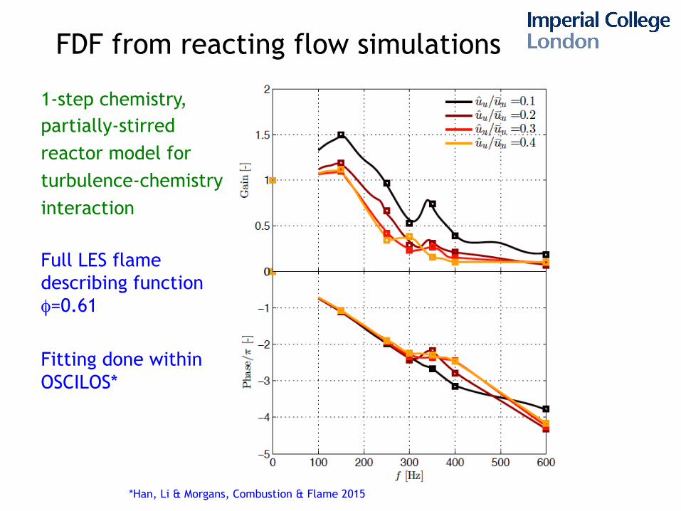
FDF from reacting flow simulations
Incompressible LES using Open Source CFD code OpenFOAM (ReactingFOAM, one-step chemistry, PaSR for turbulence-combustion interaction, WALE SGS) Equiv ratio φ = 0.55, flame response to velocity forcing at 160Hz (A=0.65)*#
*Han, Li & Morgans, Combustion & Flame 2015
FDF from reacting flow simulations
Full LES flame describing function φ=0.61
Fitting done within OSCILOS*
*Han, Li & Morgans, Combustion & Flame 2015
1-step chemistry, partially-stirred reactor model for turbulence-chemistry interaction
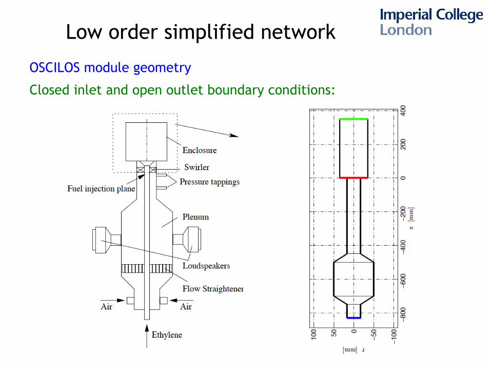
Low order simplified network
OSCILOS module geometry
Closed inlet and open outlet boundary conditions:
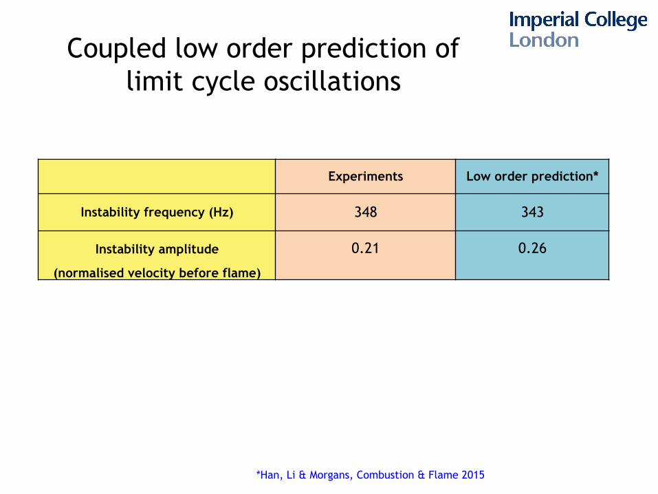
Coupled low order prediction of limit cycle oscillations
*Han, Li & Morgans, Combustion & Flame 2015
Experiments Low order prediction*
Instability frequency (Hz) 348 343
Instability amplitude 0.21 0.26
(normalised velocity before flame)
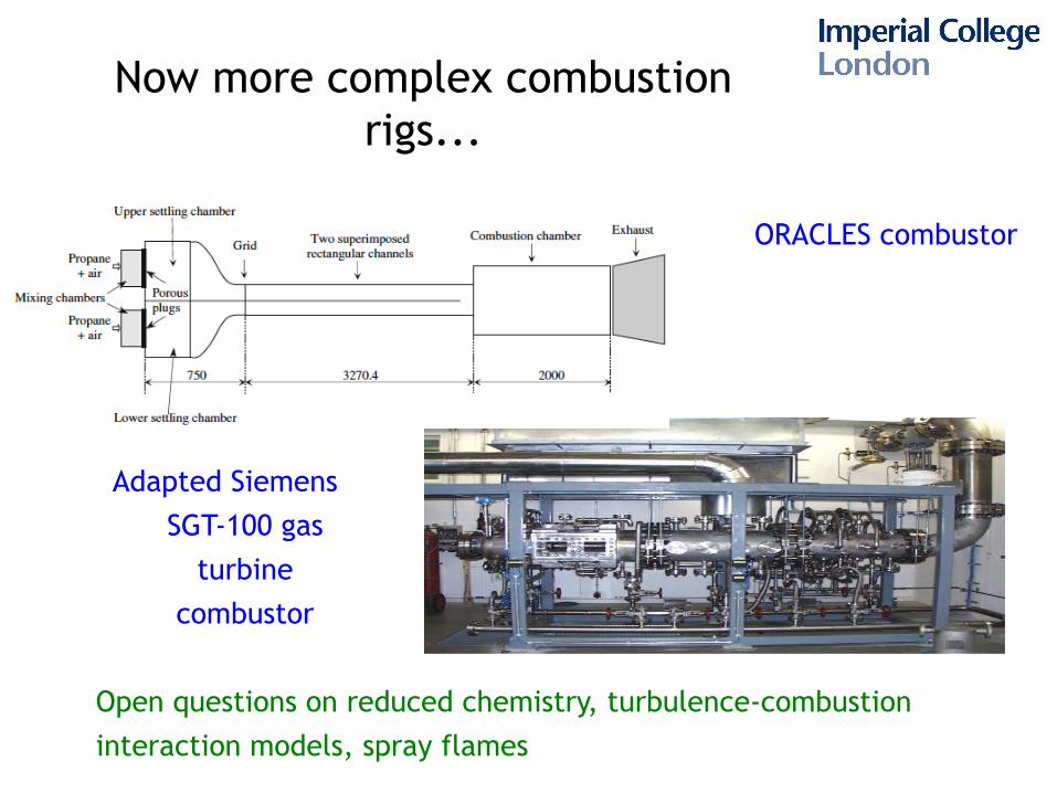
Now more complex combustion rigs...
Adapted Siemens SGT-100 gas
turbine combustor
ORACLES combustor
Open questions on reduced chemistry, turbulence-combustion interaction models, spray flames
Indirect combustion noise (entropy noise)
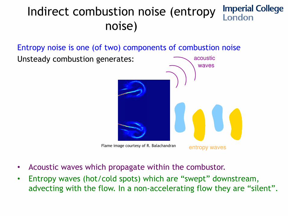
Entropy noise is one (of two) components of combustion noise Unsteady combustion generates:
• Acoustic waves which propagate within the combustor.
• Entropy waves (hot/cold spots) which are “swept” downstream, advecting with the flow. In a non-accelerating flow they are “silent”.
entropy waves
acoustic
waves
Flame image courtesy of R. Balachandran
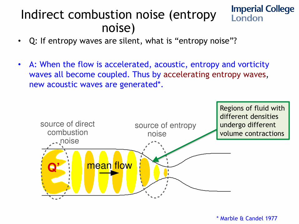
• Q: If entropy waves are silent, what is “entropy noise”?
• A: When the flow is accelerated, acoustic, entropy and vorticity waves all become coupled. Thus by accelerating entropy waves, new acoustic waves are generated*.
noise
Q’ mean flow
source of directcombustion
noise
source of entropy
Regions of fluid with different densities undergo different volume contractions
* Marble & Candel 1977
Indirect combustion noise (entropy noise)
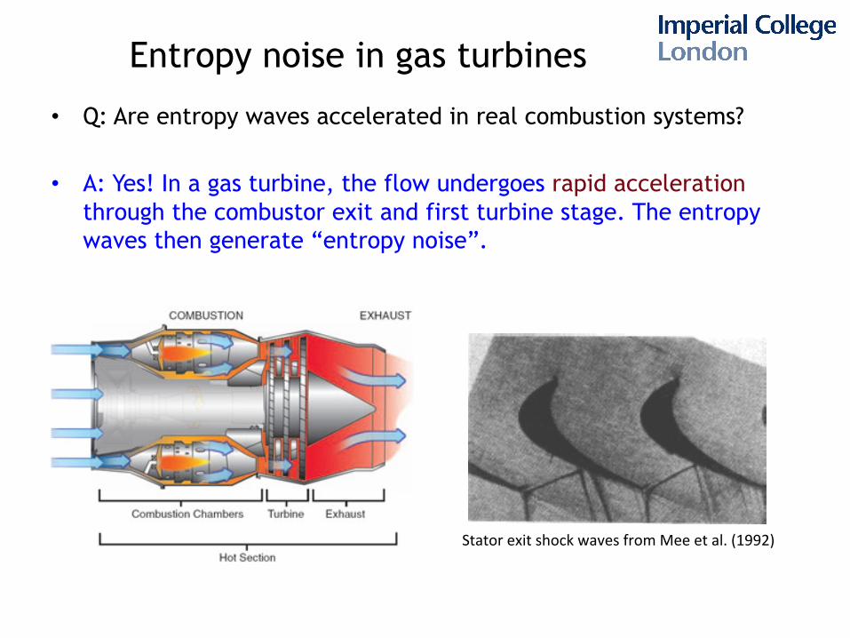
Entropy noise in gas turbines
• Q: Are entropy waves accelerated in real combustion systems?
• A: Yes! In a gas turbine, the flow undergoes rapid acceleration through the combustor exit and first turbine stage. The entropy waves then generate “entropy noise”.
Stator exit shock waves from Mee et al. (1992)
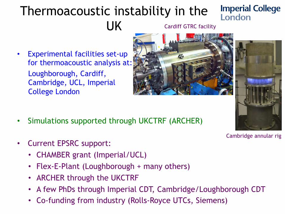
Thermoacoustic instability in the UK
• Simulations supported through UKCTRF (ARCHER)
• Current EPSRC support: • CHAMBER grant (Imperial/UCL) • Flex-E-Plant (Loughborough + many others) • ARCHER through the UKCTRF • A few PhDs through Imperial CDT, Cambridge/Loughborough CDT • Co-funding from industry (Rolls-Royce UTCs, Siemens)
• Experimental facilities set-up for thermoacoustic analysis at: Loughborough, Cardiff, Cambridge, UCL, Imperial College London
Cardiff GTRC facility
Cambridge annular rig
Thermoacoustic instability in the UK
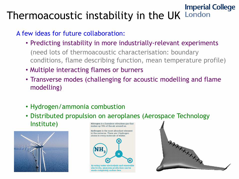
A few ideas for future collaboration: • Predicting instability in more industrially-relevant experiments
(need lots of thermoacoustic characterisation: boundary conditions, flame describing function, mean temperature profile) • Multiple interacting flames or burners • Transverse modes (challenging for acoustic modelling and flame
modelling)
• Hydrogen/ammonia combustion • Distributed propulsion on aeroplanes (Aerospace Technology
Institute)