Embed Size (px)
Citation preview
THERMODYNAMIC INVESTIGATION OF ORGANIC RANKINE CYCLE (ORC) ENERGY
RECOVERY SYSTEM AND RECENT STUDIES
Özlem BOYDAK1*
, İsmail EKMEKÇİ2, Mustafa YILMAZ
3, Hasan KÖTEN
4
1 Istanbul Medeniyet University, Kuzey Kampüsü 34700 Unalan, Uskudar, Istanbul / TURKEY
2 İstanbul Ticaret University, Küçükyalı Kampüsü 34840, Küçükyalı, Istanbul / TURKEY
3 Marmara University, Göztepe Kampüsü 34722 Kadıköy, Istanbul / TURKEY
4 Istanbul Medeniyet University, Kuzey Kampüsü 34700 Unalan, Uskudar, Istanbul / TURKEY
* E-mail: [email protected]
Recently, new environment-friendly energy conversion technologies are
required for using energy resources valid to power generation. Accordingly,
low-grade heat sources as solar heat, geothermal energy, and waste heat,
which have available temperatures ranging between 60 and 200°C, are
supposed as applicants for recent new generation energy resources. As an
alternative energy source, such low-grade heat sources usage generating
electricity with the help of power turbine cycles was examined through this
study. Such systems have existing technologies applicable at low
temperatures and a compact structure at low cost, however, these systems
have a low thermal efficiency of the Rankine cycles operated at low
temperatures. An Organic Rankine Cycle (ORC) is alike to a conventional
steam power plant, except the working fluid, which is an organic, high
molecular mass fluid with a liquid-vapor phase change, or boiling point, at a
lower temperature than the water-steam phase change. The efficiency of an
ORC is about between 10% and 20%, depending on temperature levels and
availability of a valid fluid.
Keywords: Organic Rankine cycle, ORC, Rankine cycle, energy recovery,
heat recovery, energy efficiency, organic Rankine cycle system, energy
recovery system.
1. Introduction
Organic Rankine Cycle (ORC) is the recent type of an environmentally friendly leading
technological system, applying the principle of the steam Rankine cycle, but can utilize relatively low-
grade heat sources below 150°C. This system uses an organic substance as a working fluid; therefore it
is named as ‘Organic’ Rankine. Thus, the system utilizes low-grade heat sources for economic energy
production and consists of an evaporator (heating area), a turbine and a condenser (cooling area).
Utilizing different kinds of working fluid instead of water/steam provides the opportunity of
constructing miniature, compact and portable thermal power plants. The selection of the architecture
will rely on heat source temperature stage and also sort of working fluid, dry or wet. ORC based new
type of power plant system is designed to use low and mid-temperature waste heat sources and to
convert them into electric energy– efficiently, economically and CO2 free. ORC systems are typically
used for four major applications: waste heat recovery, geothermal power plants, biomass combustion
plants and solar thermal plants [1,2,3].
The most developed application for an ORC system is the so-called “waste heat recovery”.
The term “waste heat recovery” may be utilized to express the use of any heat overall ejected to the
environment. Thus, the ORC system is a useful way of heat recovery in the temperature range between
150 to 200 °C; especially if no other utilization for the waste heat is present on the site [4,5,6].
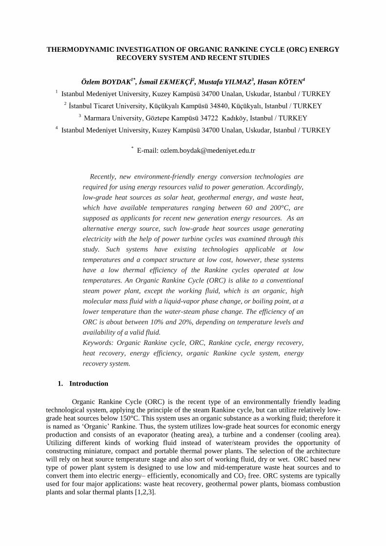
Figure 1. (ORC) Organic Rankine cycle overview
ORC is simpler and economically more feasible than the steam Rankine cycle. Thus, many
commercial and test plants can be made by using organic Rankine cycle due to its advantages. The
ORC system exhibits great flexibility, high safety and low maintenance requirements in recovering
this grade of waste heat. Integrating the ORC to the energy system, such as power plants, could
achieve using low-grade energy (waste heat) to generate high-grade energy (power), easing the power
burden and enhancing system efficiency. Since the ORC consumes virtually no additional fuel, for the
same added power, the emission of environmental pollutants such as carbon dioxide (CO2), sulfur
dioxide (SO2) and so on would be decreased. What’s more, according to the local demand, the exhaust
heat exiting from the ORC could be further utilized to drive chillers such as absorption chillers to
supply cooling capacity. The ORC technology is a newly emerged technology since 1961. Thus, its
usage is not so common in our country [7,8,9].
The Organic Rankine Cycle transforms thermal energy into mechanical shaft power. The
advantage of ORC systems is the return of useful energy, often as electrical turnout, from low-energy
resources such as the low-pressure steam affiliated with steam-driven turbines used for electricity
generation [10,11,12].
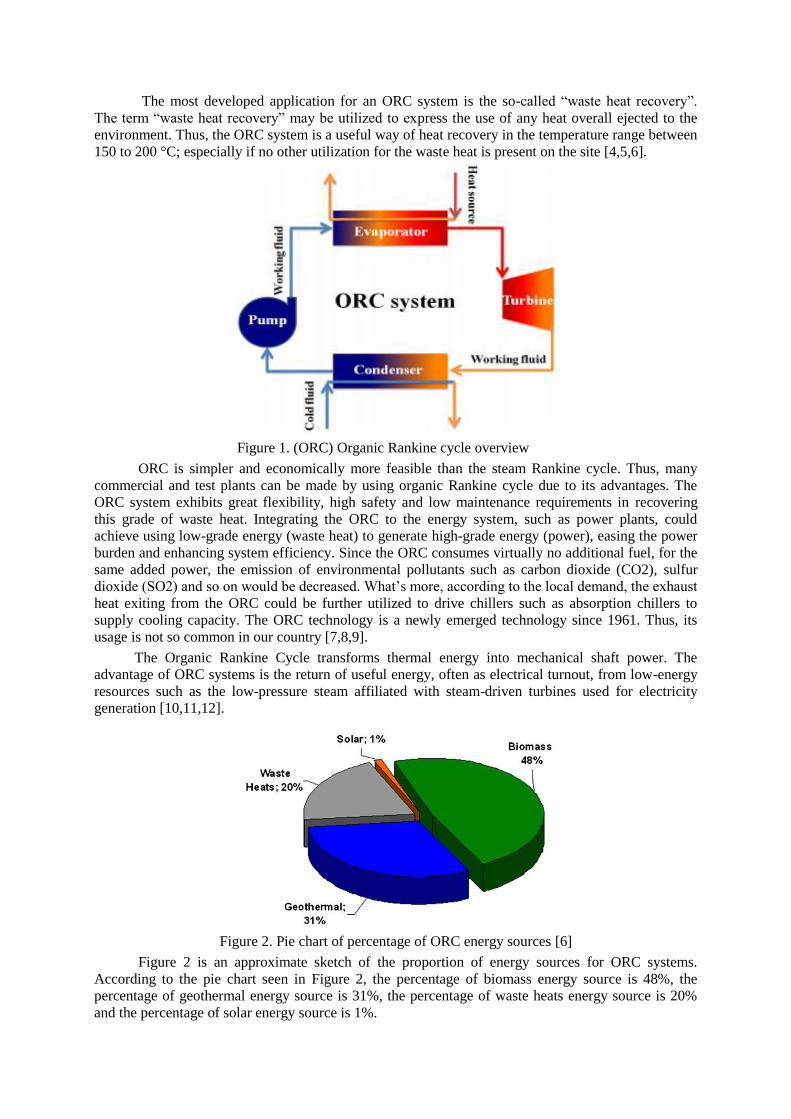
Figure 2. Pie chart of percentage of ORC energy sources [6]
Figure 2 is an approximate sketch of the proportion of energy sources for ORC systems.
According to the pie chart seen in Figure 2, the percentage of biomass energy source is 48%, the
percentage of geothermal energy source is 31%, the percentage of waste heats energy source is 20%
and the percentage of solar energy source is 1%.
2. ORC Energy Recovery System Overview
An Organic Rankine Cycle (ORC) is energy recovery system shown in Figure 1, like a
traditional Rankine steam system, except the organic working fluid, which is high molecular mass
fluid with a liquid-vapor phase change, or boiling point at a lower temperature than the water-steam
phase transition [13,14,15].
The low-temperature heat is transformed into useful work to be transformed into electricity.
Selection of the fluid of ORC system relies on the temperatures of the thermal sink and also the
thermal source [16,17,18].
ORC energy recovery system is a closed loop consisting four fundamental functions:
• 1–2 Pump Compression: A feed pump make liquid working fluid is pressurized.
• 2–3 Boiler Vaporization: The liquid working fluid takes thermal energy in and vaporizes to the steam
phase. Evaporators provide the heat transfer from the heat carrier fluid to the working fluid.
• 3–4 Expansion by an expander: An expander transforms the heat energy of the working fluid into
mechanical energy, which is the power generating operation. Then, an alternator makes this
mechanical energy to be transformed into electricity.
• 4–1 Condensation by a condenser: The steam fluid condenses into the liquid phase, which is the heat-
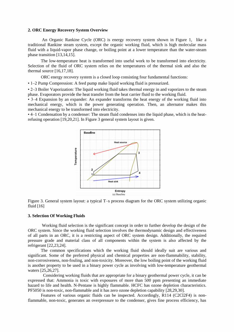
refusing operation [19,20,21]. In Figure 3 general system layout is given.
Figure 3. General system layout: a typical T–s process diagram for the ORC system utilizing organic
fluid [16]
3. Selection Of Working Fluids
Working fluid selection is the significant concept in order to further develop the design of the
ORC system. Since the working fluid selection involves the thermodynamic design and effectiveness
of all parts in an ORC, it is a restricting aspect of ORC system design. Additionally, the required
pressure grade and material class of all components within the system is also affected by the
refrigerant [22,23,24].
The common specifications which the working fluid should ideally suit are various and
significant. Some of the preferred physical and chemical properties are non-flammability, stability,
non-corrosiveness, non-fouling, and non-toxicity. Moreover, the low boiling point of the working fluid
is another property to be used in a binary power cycle as involving with low-temperature geothermal
waters [25,26,27].
Considering working fluids that are appropriate for a binary geothermal power cycle, it can be
expressed that: Ammonia is toxic with exposures of more than 500 ppm presenting an immediate
hazard to life and health. N-Pentane is highly flammable. HCFC has ozone depletion characteristics.
PF5050 is non-toxic, non-flammable and it has zero ozone depletion capability [28,29,30].
Features of various organic fluids can be inspected. Accordingly, R114 (C2Cl2F4) is non-
flammable, non-toxic, generates an overpressure to the condenser, gives fine process efficiency, has
adequate thermal stability and permits the utilization of a low-cost, single stage turbine. It should be
noticed that the full lack of oil (due to high-speed technology) essentially enhances the thermal
stability of R114. However, since R114 is a CFC-compound, it is essential to discover other options.
Because the process is hermetic, there is no actual hazard for the ozone layer, yet by utilizing a CFC-
compound it is hard to satisfy the international requirements. Thus, other fluids, fluorine-85 and
toluene (C6H5CH3), can be analyzed for the other prototype builts. The amount of thermal
decomposition of toluene in oil-free circumstances is very low up to about 400°C. In terms of low-
temperature applications, isobutane (C4H10) is found to be rather appropriate. In that circumstances, it
follows better than toluene to be cooled. Common refrigerants utilized within ORC systems were
outlined and summarized in Table 1 [31,32,33].
R-134a is readily accessible, low cost and widely used in the refrigeration industry as a
working fluid. The thermodynamic efficiency of R-134a at temperatures higher than 50°C was
detected to be amazingly deficient. Higher process pressures also declined the safety factor of
experimental components. Therefore, a more profitable refrigerant can be selected. A refrigerant mix
called HFC-M1 can be chosen for utilization with the ORC test bed. HFC-M1 is a mix of 50% R-
245fa and 50% R-365mfc. A boiling temperature of 30°C
at atmospheric conditions also reinforces the facility of management of this refrigerant as shown in
Table 1 [34,35,36].
Lower boiling point and dry saturation curve are some of the various advantages of the
refrigerant offer over water which is advantageous for the system efficiency since the steam flowing
through the turbine is not a wet mixture [36,37,38].
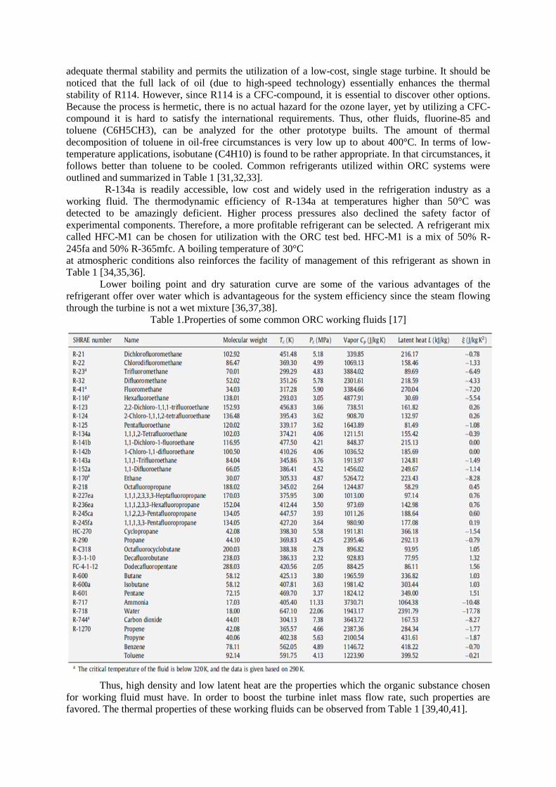
Table 1.Properties of some common ORC working fluids [17]
Thus, high density and low latent heat are the properties which the organic substance chosen
for working fluid must have. In order to boost the turbine inlet mass flow rate, such properties are
favored. The thermal properties of these working fluids can be observed from Table 1 [39,40,41].
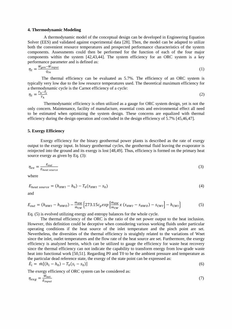
4. Thermodynamic Modeling
A thermodynamic model of the conceptual design can be developed in Engineering Equation
Solver (EES) and validated against experimental data [28]. Then, the model can be adapted to utilize
both the convenient resource temperatures and prospected performance characteristics of the system
components. Assessments could then be performed for the function of each of the four major
components within the system [42,43,44]. The system efficiency for an ORC system is a key
performance parameter and is defined as:
(1)
The thermal efficiency can be evaluated as 5.7%. The efficiency of an ORC system is
typically very low due to the low resource temperatures used. The theoretical maximum efficiency for
a thermodynamic cycle is the Carnot efficiency of a cycle:
(2)
Thermodynamic efficiency is often utilized as a gauge for ORC system design, yet is not the
only concern. Maintenance, facility of manufacture, essential costs and environmental effect all need
to be estimated when optimizing the system design. These concerns are equalized with thermal
efficiency during the design operation and concluded in the design efficiency of 5.7% [45,46,47].
5. Exergy Efficiency
Exergy efficiency for the binary geothermal power plants is described as the rate of exergy
output to the exergy input. In binary geothermal cycles, the geothermal fluid leaving the evaporator is
reinjected into the ground and its exergy is lost [48,49]. Thus, efficiency is formed on the primary heat
source exergy as given by Eq. (3):
(3)
where
(4)
and
(5)
Eq. (5) is evolved utilizing energy and entropy balances for the whole cycle.
The thermal efficiency of the ORC is the ratio of the net power output to the heat inclusion.
However, this definition could be deceptive when considering various working fluids under particular
operating conditions if the heat source of the inlet temperature and the pinch point are set.
Nevertheless, the diversities of the thermal efficiency is straightly related to the variations of Wnet
since the inlet, outlet temperatures and the flow rate of the heat source are set. Furthermore, the exergy
efficiency is analyzed herein, which can be utilized to gauge the efficiency for waste heat recovery
since the thermal efficiency can not indicate the capability to transform energy from low-grade waste
heat into functional work [50,51]. Regarding P0 and T0 to be the ambient pressure and temperature as
the particular dead reference state, the exergy of the state point can be expressed as:
(6)
The exergy efficiency of ORC system can be considered as:
(7)
6. ORC Power Plant Design And Testing
The major modules can be designed as standard modules, which constitute the ORC energy
plant, which means the power plant can simply be conformed to any waste heat origin by only
transforming the central cycle to the particular industry plant. The switch module is designed for stable
operating process circumstances. Furthermore, the power plant can be designed to only utilize a
limited surface area, due to a rather compact constitution [52,53].
Temperature, pressure and flow rate data is obtained throughout the system to permit the
utilizer to process the system and attain a steady state at the requested process conditions. A
CompacDAQ can be utilized for data acquisition and also permits the system performance to be
calculated. Presently, the system will require to be commanded by the utilizer, however as the system
dynamics are comprehended better PID control will able to be enabled. Constitution of the system can
be accomplished throughout nearly one year and then the system can be prompt for testing. Most of
the components chosen are readily accessible which shortened the fabrication time plan. Extra caution
should be taken throughout the constitution and assembly operations in order to assure no leakage in
the system, which avoids a deficit of refrigerant [54,55,56].
Figure 4. Illustration of ORC power plant [40]
The compact and modular design of the power plant is demonstrated in Figure 4; all
components requiring monitoring or maintenance (electro-mechanical parts such as turbine, pumps,
generator, valves etc.) are fixed at the lowest stage. The median floor stage includes every static
systematic component as process heat exchangers, piping. Additionally, the condensers are beared by
the top of the steel body [57,58]. The system can be merged in almost any industrial processes due to
its modular design. The two-cycle system provides an adaptable integration in current plants. The
flexibility in its function permits for economic utilization of waste heat with temperatures beginning
from 150°C to produce power from 500 kW to double-digit MW [59,60].
The ORC power plant is -from the cement maker's perspective- an installation of secondary
significance, thus it must not intervene in or even disrupt the main process of cement manufacturing.
This requirement is performed by fixing the heat exchangers in a bypass mode. If the ORC power
plant should somehow be out of service, while the kiln is under full operation, the waste gas bypasses
the heat exchanger and takes the regular path through the cooling tower. In bypass mode, the clinker
cooler air is cooled in the existing cooler before it arrives the dust precipitator [61,62,63].
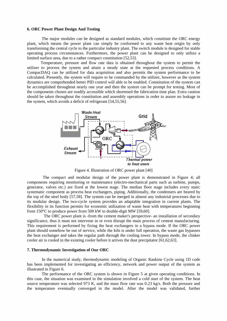
7. Thermodynamic Investigation of Our ORC
In the numerical study, thermodynamic modeling of Organic Rankine Cycle using 1D code
has been implemented for investigating an efficiency, network and power output of the system as
illustrated in Figure 6.
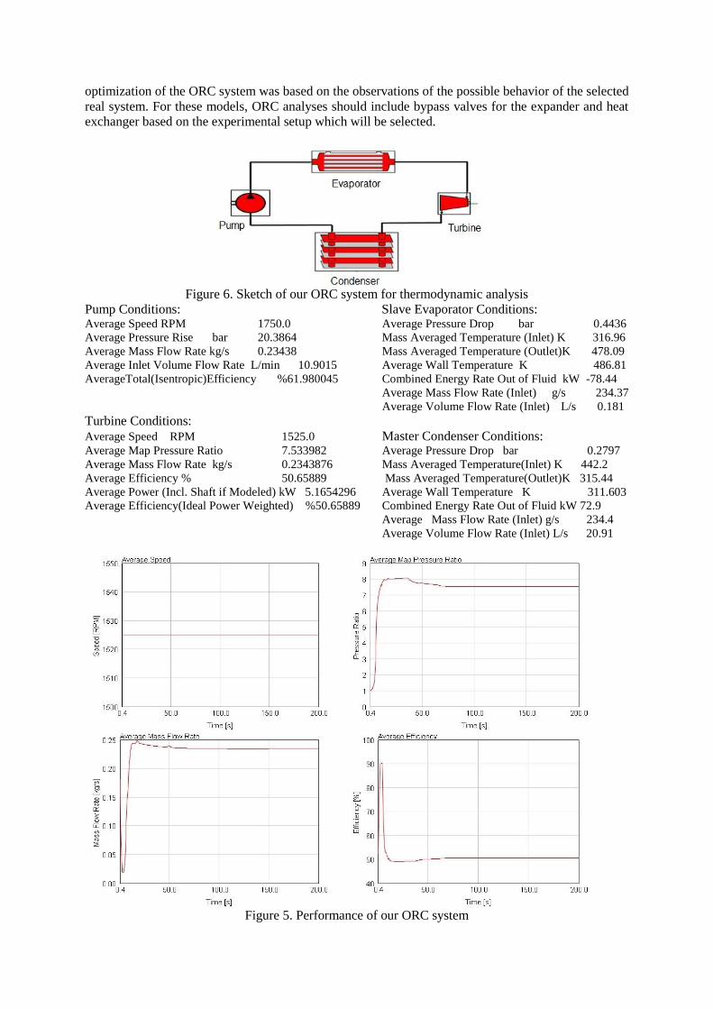
The performance of the ORC system is shown in Figure 5 at given operating conditions. In
this case, the situation was examined in the simulation involved a cold start of the system. The heat
source temperature was selected 973 K, and the mass flow rate was 0.23 kg/s. Both the pressure and
the temperature eventually converged in the model. After the model was validated, further
optimization of the ORC system was based on the observations of the possible behavior of the selected
real system. For these models, ORC analyses should include bypass valves for the expander and heat
exchanger based on the experimental setup which will be selected.
Figure 6. Sketch of our ORC system for thermodynamic analysis
Pump Conditions: Slave Evaporator Conditions: Average Speed RPM 1750.0 Average Pressure Drop bar 0.4436
Average Pressure Rise bar 20.3864 Mass Averaged Temperature (Inlet) K 316.96
Average Mass Flow Rate kg/s 0.23438 Mass Averaged Temperature (Outlet)K 478.09
Average Inlet Volume Flow Rate L/min 10.9015 Average Wall Temperature K 486.81
AverageTotal(Isentropic)Efficiency %61.980045 Combined Energy Rate Out of Fluid kW -78.44
Average Mass Flow Rate (Inlet) g/s 234.37
Average Volume Flow Rate (Inlet) L/s 0.181
Turbine Conditions:
Average Speed RPM 1525.0 Master Condenser Conditions: Average Map Pressure Ratio 7.533982 Average Pressure Drop bar 0.2797
Average Mass Flow Rate kg/s 0.2343876 Mass Averaged Temperature(Inlet) K 442.2
Average Efficiency % 50.65889 Mass Averaged Temperature(Outlet)K 315.44
Average Power (Incl. Shaft if Modeled) kW 5.1654296 Average Wall Temperature K 311.603
Average Efficiency(Ideal Power Weighted) %50.65889 Combined Energy Rate Out of Fluid kW 72.9
Average Mass Flow Rate (Inlet) g/s 234.4
Average Volume Flow Rate (Inlet) L/s 20.91
Figure 5. Performance of our ORC system
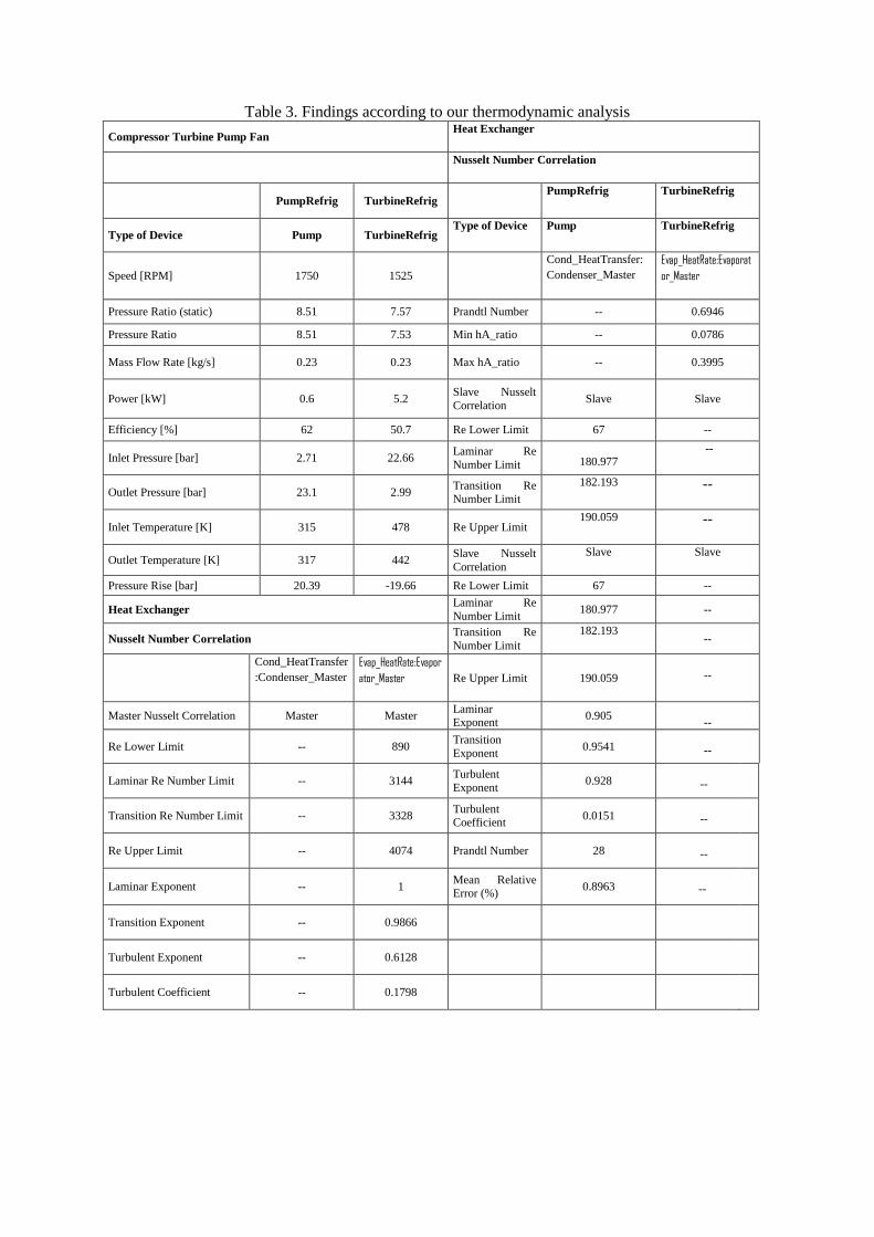
Table 3. Findings according to our thermodynamic analysis
Compressor Turbine Pump Fan Heat Exchanger
Nusselt Number Correlation
PumpRefrig TurbineRefrig PumpRefrig TurbineRefrig
Type of Device Pump TurbineRefrig Type of Device Pump TurbineRefrig
Speed [RPM] 1750 1525
Cond_HeatTransfer:
Condenser_Master Evap_HeatRate:Evaporat
or_Master
Pressure Ratio (static) 8.51 7.57 Prandtl Number -- 0.6946
Pressure Ratio 8.51 7.53 Min hA_ratio -- 0.0786
Mass Flow Rate [kg/s] 0.23 0.23 Max hA_ratio -- 0.3995
Power [kW] 0.6 5.2 Slave Nusselt
Correlation Slave Slave
Efficiency [%] 62 50.7 Re Lower Limit 67 --
Inlet Pressure [bar] 2.71 22.66 Laminar Re
Number Limit
180.977
--
Outlet Pressure [bar] 23.1 2.99 Transition Re Number Limit
182.193 --
Inlet Temperature [K] 315 478 Re Upper Limit 190.059 --
Outlet Temperature [K] 317 442 Slave Nusselt
Correlation
Slave Slave
Pressure Rise [bar] 20.39 -19.66 Re Lower Limit 67 --
Heat Exchanger Laminar Re
Number Limit 180.977 --
Nusselt Number Correlation Transition Re
Number Limit
182.193 --
Cond_HeatTransfer
:Condenser_Master Evap_HeatRate:Evapor
ator_Master Re Upper Limit 190.059
--
Master Nusselt Correlation Master Master Laminar Exponent
0.905
--
Re Lower Limit -- 890 Transition
Exponent 0.9541
--
Laminar Re Number Limit -- 3144 Turbulent
Exponent 0.928
--
Transition Re Number Limit -- 3328 Turbulent Coefficient
0.0151
--
Re Upper Limit -- 4074 Prandtl Number 28
--
Laminar Exponent -- 1 Mean Relative Error (%)
0.8963
--
Transition Exponent -- 0.9866
Turbulent Exponent -- 0.6128
Turbulent Coefficient -- 0.1798
8. Conclusion
This paper investigates an ORC system for the industrial waste heat as the focus is on the
waste heat recovery application. The organic Rankine cycle (ORC) is generally recognized as an
applicable technology to transform low-temperature heat into electricity. Moreover, ORCs are
designed for the unmanned process with a small amount of maintenance. Industrial waste heat, solar
heat, geothermal energy and biomass combustion heat are recoverable energy resources. Organic
Rankine cycle (ORC) energy recovery system was modeled and reviewed. In addition, a
comprehensive literature survey is carried out. Thus, many recent papers about ORC have studied over
accordingly in the literature section. Then, they were expressed in this paper in order, to sum up. A
thermodynamic analysis was also carried out on an ORC system throughout this paper. Binary fluid
cycles utilize a blend of water/ammonia, yet are rather complicated compared to Rankine cycles.
Additionally, the organic substance chosen for the working fluid must have low latent heat and high
density to boost the turbine inlet mass flow rate. Typical features of an ORC module are indicated as
heat source temperature, power output, thermal efficiency, etc. The maximum thermal efficiency of a
module is about 25%. The choice of a module is basically founded upon operation, heat source
temperature and aimed power output. The selection of the sort of organic Rankine cycle machine is
commonly affected by the nature, condition, and temperature of the heat source. Thus, the temperature
is a critical property during selection in case studies. According to results, the system varies according
to technology, size and cost aspects. Moreover, machine, engineering, system integration, capital costs
are contained in the investment cost of an ORC Project and also the investment cost is closely related
to the application.
Since the ORC consumes virtually no additional fuel, the emission of environmental
pollutants such as carbon dioxide (CO2), sulfur dioxide (SO2) and etc. would be decreased. Moreover,
the exhaust heat exiting from the ORC could be further used to drive chillers such as absorption
chillers to supply cooling capacity if required by the local demand. Moreover, further work is needed
to enhance the ORC's performance, such as decreasing the heat and pressure losses in the whole
system and developing the performance of the common parts such as the turbine, generator, and heat
exchangers.
Nomenclature
°C or K Degree Celsius or Kelvin
C Heat capacity [kJ/Kg K]
x Exergy rate (kW)
Ex Specific exergy (kJ/kg)
g Acceleration due to gravity [m/s2]
h Specific enthalpy (kJ/kg)
Mass flow rate (kg/s)
P Pressure (kPa)
Heat rate (kW)
Rg Gas constant
s Specific entropy (kJ/kgK)
t Temperature [°C]
Work rate (kW)
x Vapour quality
V Velocity [m/s]
Greek symbols
η Energy efficiency
ψ Exergy efficiency
Subscripts
ORC Organic Rankine cycle
T Turbine
1, 2. . .46 State numbers
0 Ambient (or reference environment) condition
References
[1] Lecompte, S. 2015. “Review of organic Rankine cycle (ORC) architectures for waste heat
recovery”, Renewable and Sustainable Energy Reviews, 47, 448-461
[2] Imran, M., Haglind, F., Asim, M., Alvid J. January 2018. “Recent research trends in organic
Rankine cycle technology: A bibliometric approach”, 81, Part 1, 552-562
[3] Tartière T., Astolfi M. 2017. “A World Overview of the Organic Rankine Cycle Market”, Energy
Procedia Energy Procedia, Volume 129, 2-9
[4] Tchanche, B. 2014. “Heat resources and organic Rankine cycle machines”, Renewable and
Sustainable Energy Reviews, 39, 1185-1199
[5] Sung T., Kim K. 2017. “An organic Rankine cycle for two different heat sources: steam and hot
water”, Energy Procedia, 129, 883-890
[6] http://www.turboden.eu/en/rankine/rankine-advantages.php
[7] Capata, R. 2014. “Preliminary design and simulation of a turbo expander for small rated power
organic Rankine cycle (ORC)”, Energies, 7, 7067-7093
[8] Rahbar, K., Mahmoud, S., Al-Dadah, R., Moazami, N. 2015. “Modelling and optimization of
organic Rankine cycle based on a small-scale radial inflow turbine”, Energy Conversion and
Management, 91, 186-198
[9] Rahbar, K., Mahmoud, S., Al-Dadah, R., Moazami, N., Mirhadizadeh S. 2017. “Review of
organic Rankine cycle for small-scale applications”, Energy Conversion and Management,
Volume 134, 135-155
[10] Eyidogan, M. 2016. “Investigation of Organic Rankine Cycle (ORC) technologies in Turkey
from the technical and economic point of view”, Renewable and Sustainable Energy Reviews, 58,
885-895
[11] http://www.infinityturbine.com/general-info.html
[12] Lei B., Wu Y., Ma C., Wang W., Zhi R. 2017. “Theoretical analyses of pressure losses in organic
rankine cycles”, Energy Conversion and Management, 153, 157–162
[13] Quoilin, S., Lemort, V., Lebrun, J. 2010. “Experimental study and modeling of an Organic
Rankine Cycle using scroll expander”, Applied Energy, 87, 1260–1268
[14] Miao Z., Xu J., Zhang K. 2017. “Experimental and modeling investigation of an organic Rankine
cycle system based on the scroll expander”, Energy, 134, 35-49
[15] Ameri, M. 2016. “Performance assessment and multi-objective optimization of an integrated
organic Rankine cycle and multi-effect desalination system”, Desalination, 392, 34-45
[16] Eyerer, S. 2016. “Experimental study of an ORC (Organic Rankine Cycle) and analysis of
R1233zd-E as a drop-in replacement for R245fa for low temperature heat utilization”, Energy,
103, 660-671
[17] Chen, H., Goswami, Y., Stefanakos, E. 2010. “A review of thermodynamic cycles and working
fluids for the conversion of low-grade heat”, Renewable and Sustainable Energy Reviews, 14,
3059–3067
[18] Pezzuolo, A. 2016. “The ORC-PD: A versatile tool for fluid selection and Organic Rankine
Cycle unit design”, Energy, 102, 605-620
[19] Hærvig, J. 2016. “Guidelines for optimal selection of working fluid for an organic Rankine cycle
in relation to waste heat recovery”, Energy, 96, 592-602
[20] Drescher, U., Bruggemann, D. 2007. “Fluid selection for the Organic Rankine Cycle (ORC) in
biomass power and heat plants”, Applied Thermal Engineering, 27, 223–228
[21] Desai, N. 2016. “Thermo-economic analysis and selection of working fluid for solar organic
Rankine cycle”, Applied Thermal Engineering, Volume 95, 471-481
[22] Xu, H. 2016. “Investigation on the fluid selection and evaporation parametric optimization for
sub- and supercritical organic Rankine cycle”, Energy, 96, 59-68
[23] Jung, H., Taylor, L., Krumdieck, S. 2015. “An experimental and modelling study of a 1 kW
organic Rankine cycle unit with mixture working fluid”, Energy, 81, 601-614
[24] Dai, X. 2016. “Chemical kinetics method for evaluating the thermal stability of Organic Rankine
Cycle working fluids”, Applied Thermal Engineering, 100, 708-713
[25] Li, J. 2016. “Effect of working fluids on the performance of a novel direct vapor generation solar
organic Rankine cycle system”, Applied Thermal Engineering, 98, 786-797
[26] Zhai, H. 2016. “Analysis of the quantitative correlation between the heat source temperature and
the critical temperature of the optimal pure working fluid for subcritical organic Rankine cycles”,
Applied Thermal Engineering, 99, 383-391
[27] Collings, P. 2016. “A dynamic organic Rankine cycle using a zeotropic mixture as the working
fluid with composition tuning to match changing ambient conditions”, Applied Energy, 171, 581-
591
[28] Chen H., Goswami D., Rahman M., Stefanakos, E. 2011. “A supercritical Rankine cycle using
zeotropic mixture working fluids for the conversion of low-grade heat into power”, Energy, 36,
549-555
[29] Rajabloo T., Iora P., Invernizzi, C. 2016. “Mixture of working fluids in ORC plants with pool
boiler evaporator”, Applied Thermal Engineering, 98, 1-9
[30] Feng Y., Hung T., Greg K., Zhang Y., Li B., Yang J., 2015. “Thermoeconomic comparison
between pure and mixture working fluids of organic Rankine cycles (ORCs) for low temperature
waste heat recovery”, Energy Conversion and Management, 106, 859-872
[31] Barse K. A., Mann M. D., 2016. “Maximizing ORC performance with optimal match of working
fluid with system design”, Applied Thermal Engineering, 100, 11-19
[32] Desideri, A. 2016. “Experimental comparison of organic fluids for low temperature ORC
(organic Rankine cycle) systems for waste heat recovery applications”, Energy, 97, 460-469
[33] Khan, S. A., Ali, M., Shehryar, M., Tanzeel-Ur-Rashid, Khalil, M. S., Ali, H. M. and Gilani, S.
I., 2017. “Performance Analysis of a Low Capacity Solar Tower Water Heating System in Climate
of Pakistan”, Energy and Buildings, 143, 84-99
[34] Khalid, O., Ali, M., Sheikh, N. A., Ali, H.M. and Manzoor, M. S. 2016. “Experimental Analysis
of An Improved Maisosenko Cycle Design under Low Velocity Conditions”, Applied Thermal
Engineering, 95, 288-295
[35] Mondejar, M., Andreasen J., Regidor, M., Riva, S., Kontogeorgis, G., Persico, G., and Haglind,
F. 2017. “Prospects of the use of nanofluids as working fluids for organic Rankine cycle power
systems”, Energy Procedia, 129, 160–167
[36] Liu L., Zhu T., Ma J. 2017. “Working fluid charge oriented off-design modeling of a small scale
Organic Rankine Cycle system” Energy Conversion and Management, 148, 944-953
[37] Shu G., Yu G, Tian H., Wei H., Liang X., Huang Z., 2016. “Multi-approach evaluations of a
cascade-Organic Rankine Cycle (C-ORC) system driven by diesel engine waste heat: Part A –
Thermodynamic evaluations”, Energy Conversion and Management, 108, 579–595
[38] Sung, T. 2016. “Thermodynamic analysis of a novel dual-loop organic Rankine cycle for engine
waste heat and LNG cold”, Applied Thermal Engineering, 100, 1031-1041
[39] Li, M. 2016. “Analytical thermal efficiency of medium-low temperature organic Rankine cycles
derived from entropy-generation analysis”, Energy, 106, 121-130
[40] Yue C., You F., Huang Y., 2016. “Thermal and economic analysis of an energy system of an
ORC coupled with vehicle air conditioning”, International Journal of Refrigeration, 64, 152–167
[41] Panesar A., Morgan R., Kennaird D. 2017. “Organic Rankine cycle thermal architecture – From
concept to demonstration”, Applied Thermal Engineering, 126, 419-428
[42] Wei, D. 2008. “Dynamic modeling and simulation of an Organic Rankine Cycle (ORC) system
for waste heat recovery”, Applied Thermal Engineering, 28, 1216–1224
[43] Nasri, F., Chaouki, A., Bacha, H. 2011. “Electricity production system from solar-heated rankine
cycle: modeling and simulation”, IJRRAS 8 (2), 176-183
[44] Karellas S., Braimakis K., 2016. “Energy–exergy analysis and economic investigation of a
cogeneration and trigeneration ORC–VCC hybrid system utilizing biomass fuel and solar power”,
Energy Conversion and Management, 107, 103–113
[45] Paanu, T., Niemi, S., Rantanen, P. 2012. “Waste Heat Recovery – Bottoming Cycle
Alternatives”, Proceedings of the University of Vaasa, Reports 175
[46] Rahbar, K. 2015. “Parametric analysis and optimization of a small-scale radial turbine for
organic Rankine cycle”, Energy, 1-16
[47] Li, G. 2016. “Organic Rankine cycle performance evaluation and thermoeconomic assessment
with various applications part I: Energy and exergy performance evaluation”, Renewable and
Sustainable Energy Reviews, 53, 477-499
[48] Desai, N., Bandyopadhyay, S. 2009. “Process integration of organic Rankine cycle”, Energy 34,
1674–1686
[49] Li, Y. 2016. “Investigation of the organic Rankine cycle (ORC) system and the radial-inflow
turbine design”, Applied Thermal Engineering, 96, 547-554
[50] Bürki, T., Börrnert, T. 2010. “Save 20% electricity by converting low temperature waste heat
into electricity”, Asean Federation of Cement Manufacturers, FCM 22nd Technical
Symposium&Exhibition, 28-34
[51] Proctor, M. 2016. “Dynamic modelling and validation of a commercial scale geothermal organic
rankine cycle power plant”, Geothermics, 61, 63-74
[52] Yamamoto, T., Furuhata, T., Arai, N., Mori, K. 2001. “Design and testing of the Organic
Rankine Cycle”, Energy 26, 239–251
[53] Landelle A., Tauveron N., Haberschill P., Revellin R., Colasson S. 2017. “Organic Rankine
cycle design and performance comparison based on experimental database”, Applied Energy, 204,
1172–1187
[54] Fu, B. 2015. “Design, construction, and preliminary results of a 250-kW organic Rankine cycle
system, Applied Thermal Engineering”, 80, 339-346
[55] Dong, S. 2016. “Optimum design method of Organic Rankine Cycle system based on semi-
empirical model and experimental validation”, Energy Conversion and Management, 108, 85-95
[56] Imran, M. 2016. “Comparative assessment of Organic Rankine Cycle integration for low
temperature geothermal heat source applications”, Energy, 102, 473-490
[57] Ahmed A., Esmaeil K., Irfan M., Al-Mufadi F. January 2018. “Design methodology of organic
Rankine cycle for waste heat recovery in cement plants”, Applied Thermal Engineering, 129, 421-
430
[58] Pu, W. 2016. “Experimental study on Organic Rankine cycle for low grade thermal energy
recovery”, Applied Thermal Engineering, 94, 221-227
[59] Zhai H., An Q., Shi L. 2018. “Zeotropic mixture active design method for organic rankine
cycle”, Applied Thermal Engineering, 129, 1171–1180
[60] Wu Q., Ren H., Gao W., Weng P., Ren J. 2018. “Design and operation optimization of organic
Rankine cycle coupled trigeneration systems”, Energy 142, 666-677
[61] Reis M., Gallo W. 1 February 2018. “Study of waste heat recovery potential and optimization of
the power production by an organic Rankine cycle in an FPSO unit”, Energy Conversion and
Management, 157, 409-422
[62] Larjola, J. 1995. “Electricity from industrial waste heat using high-speed organic Rankine cycle
(ORC)”, Int. J. Production Economics, 41, 227-235
[63] Olsen D., Abdelouadoud Y., Liem P., Wellig B. 2017. “The Role of Pinch Analysis for Industrial
ORC Integration”, Energy Procedia, 129, September 2017, 74-81


![Case Study of an Organic Rankine Cycle (ORC) for Waste ... · PDF fileCase Study of an Organic Rankine Cycle (ORC) ... in this work, the integration of ... Kalina cycle [6], Goswami](https://img.pdfslide.net/doc/110x75/5aafbc427f8b9a5d0a8dd525/case-study-of-an-organic-rankine-cycle-orc-for-waste-study-of-an-organic-rankine.jpg)


![Charge-sensitive modelling of organic Rankine cycle power ......Rankine cycle (ORC) is used to name the system [3]. A common aspect of most ORC power systems is the versatile nature](https://img.pdfslide.net/doc/110x75/61273944f76916283757524d/charge-sensitive-modelling-of-organic-rankine-cycle-power-rankine-cycle.jpg)