Embed Size (px)
Citation preview
Thermodynamics IIChapter 4
Internal Combustion Engines
Mohsin Mohd SiesFakulti Kejuruteraan Mekanikal,
Universiti Teknologi Malaysia

Coverage• Introduction• Operation of IC Engines• Ideal Cycles
– Otto Cycle– Diesel Cycle– Dual Cycle
• Parameters– Power– Mean Effective Pressure– Compression Ratio– Cut-off Ratio– Thermal Efficiency
• Reciprocating EnginePerformance– Dynamometer– Rates– Mean Piston Speed– Power– Mean Effective Pressure– Thermal Efficiency– Volumetric Efficiency– Mechanical Efficiency– Specific Fuel
Consumption
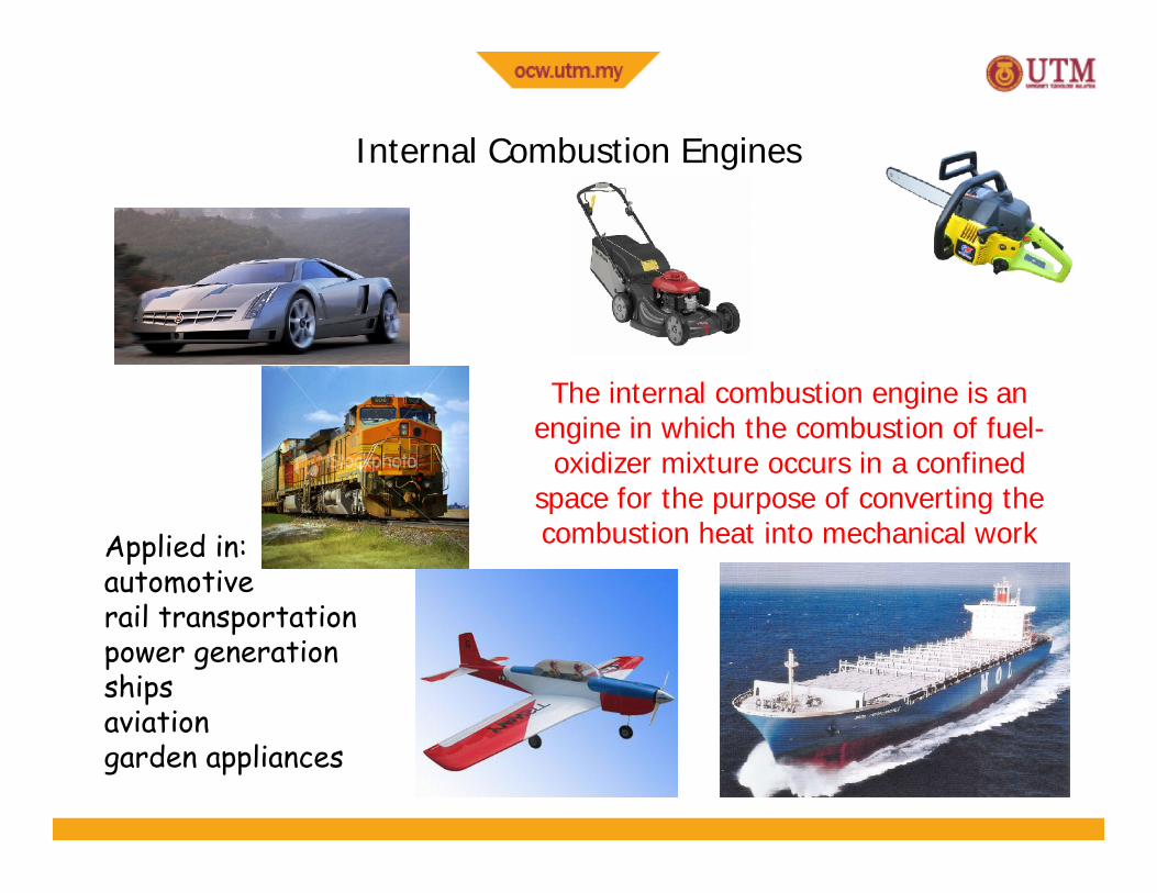
Internal Combustion Engines
The internal combustion engine is anengine in which the combustion of fuel-
oxidizer mixture occurs in a confinedspace for the purpose of converting thecombustion heat into mechanical workApplied in:
automotiverail transportationpower generationshipsaviationgarden appliances
IC Engine Operation
• IC Engines operate as– 4 stroke– 2 stroke– Petrol– Diesel
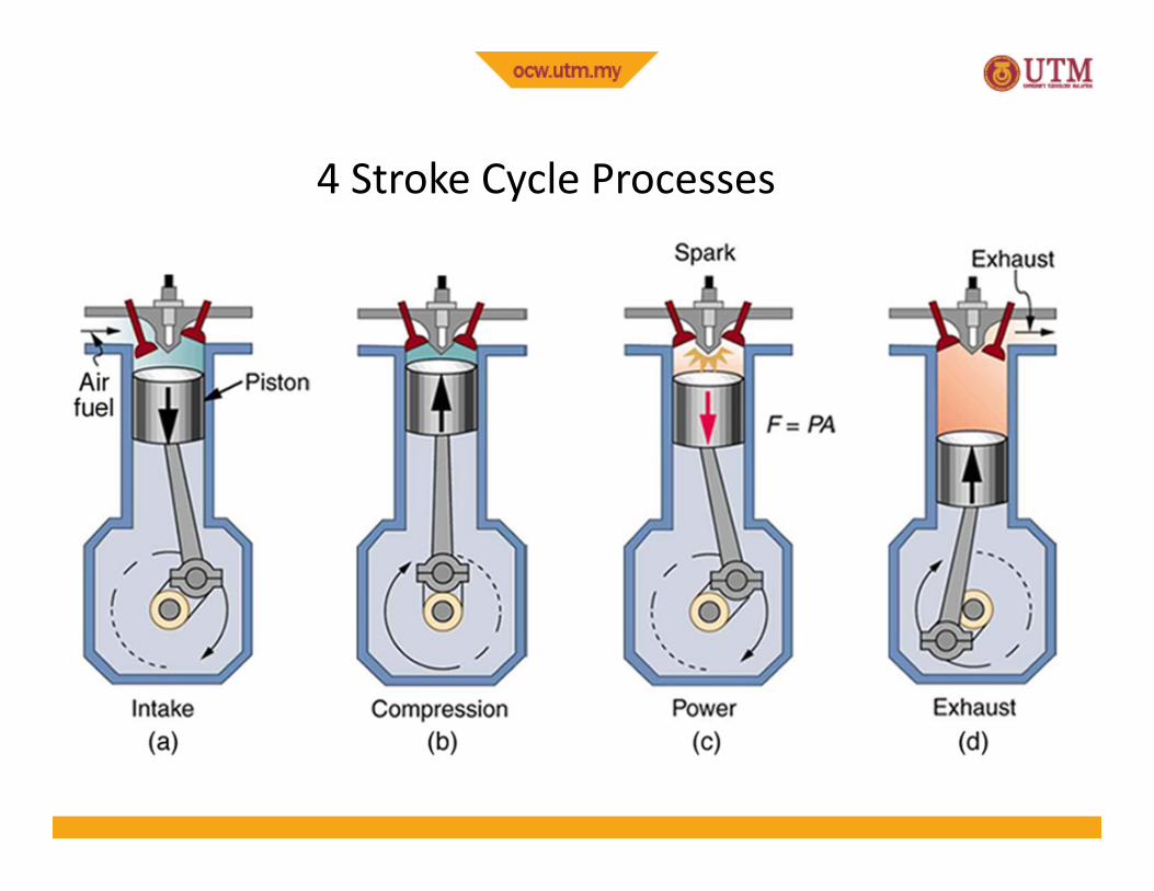
4 Stroke Cycle Processes
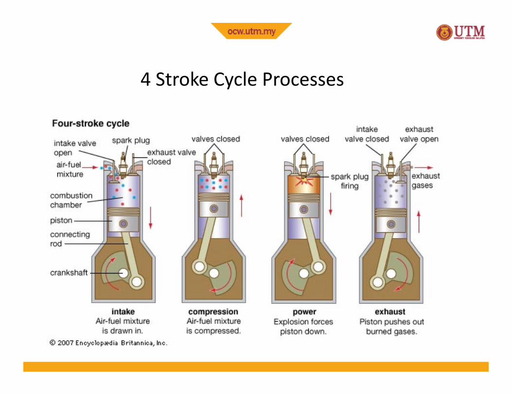
4 Stroke Cycle Processes
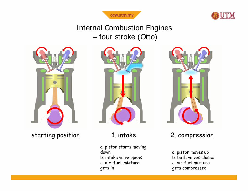
Internal Combustion Engines– four stroke (Otto)
starting position
a. piston starts movingdownb. intake valve opensc. air-fuel mixturegets in
1. intake
a. piston moves upb. both valves closedc. air-fuel mixturegets compressed
2. compression
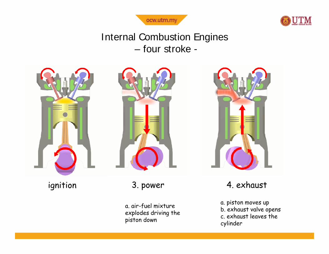
Internal Combustion Engines– four stroke -
ignition
a. air-fuel mixtureexplodes driving thepiston down
3. power
a. piston moves upb. exhaust valve opensc. exhaust leaves thecylinder
4. exhaust
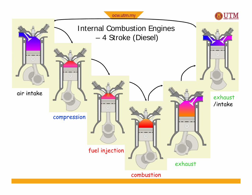
Internal Combustion Engines– 4 Stroke (Diesel)
air intake
compression
fuel injection
combustion
exhaust
exhaust/intake
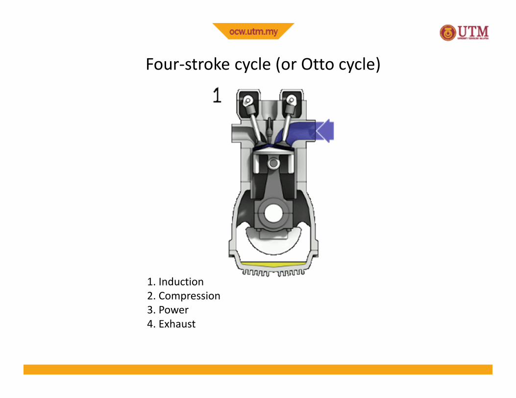
1. Induction2. Compression3. Power4. Exhaust
Four-stroke cycle (or Otto cycle)
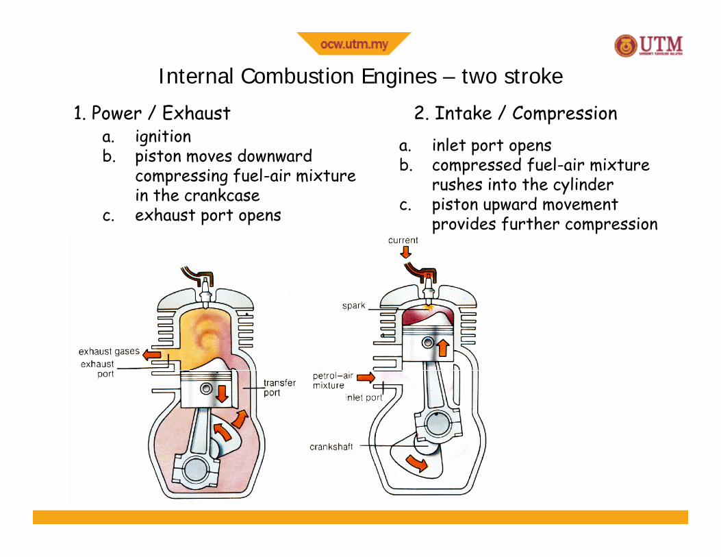
Internal Combustion Engines – two stroke1. Power / Exhaust 2. Intake / Compression
a. ignitionb. piston moves downward
compressing fuel-air mixturein the crankcase
c. exhaust port opens
a. inlet port opensb. compressed fuel-air mixture
rushes into the cylinderc. piston upward movement
provides further compression
Power / Exhaust (& Transfer)Intake / Compression
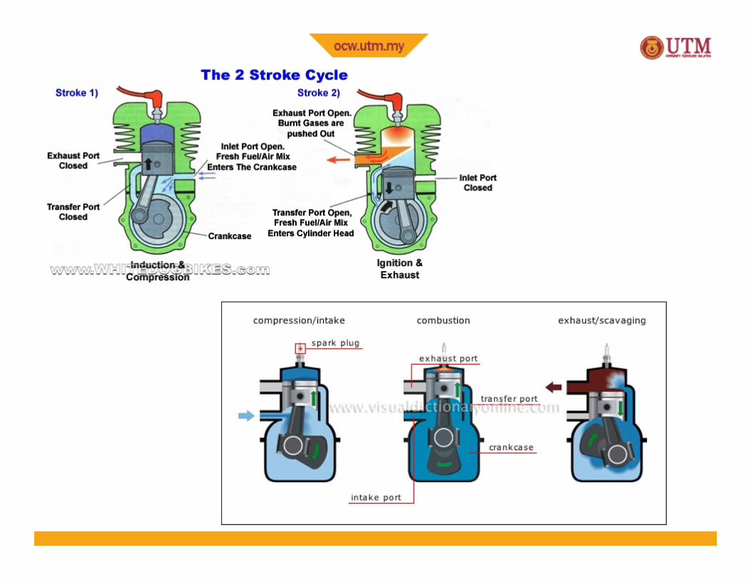
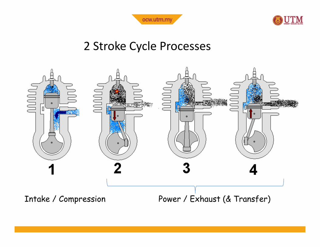
2 Stroke Cycle Processes
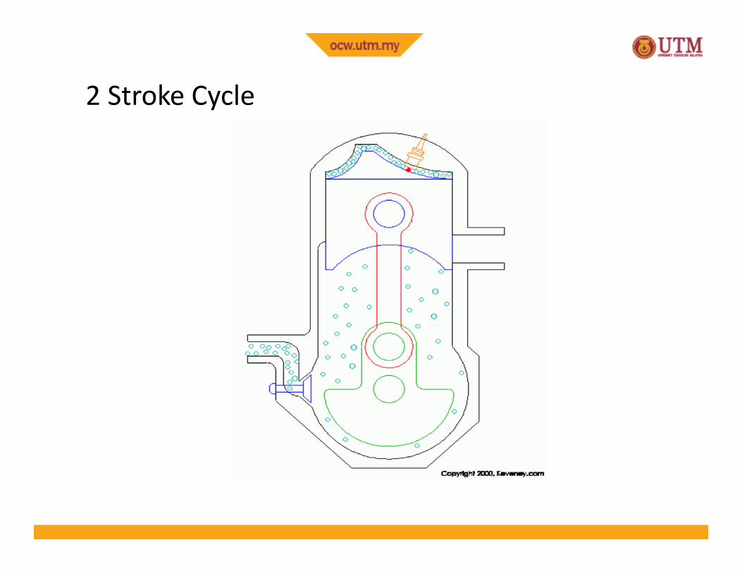
2 Stroke Cycle
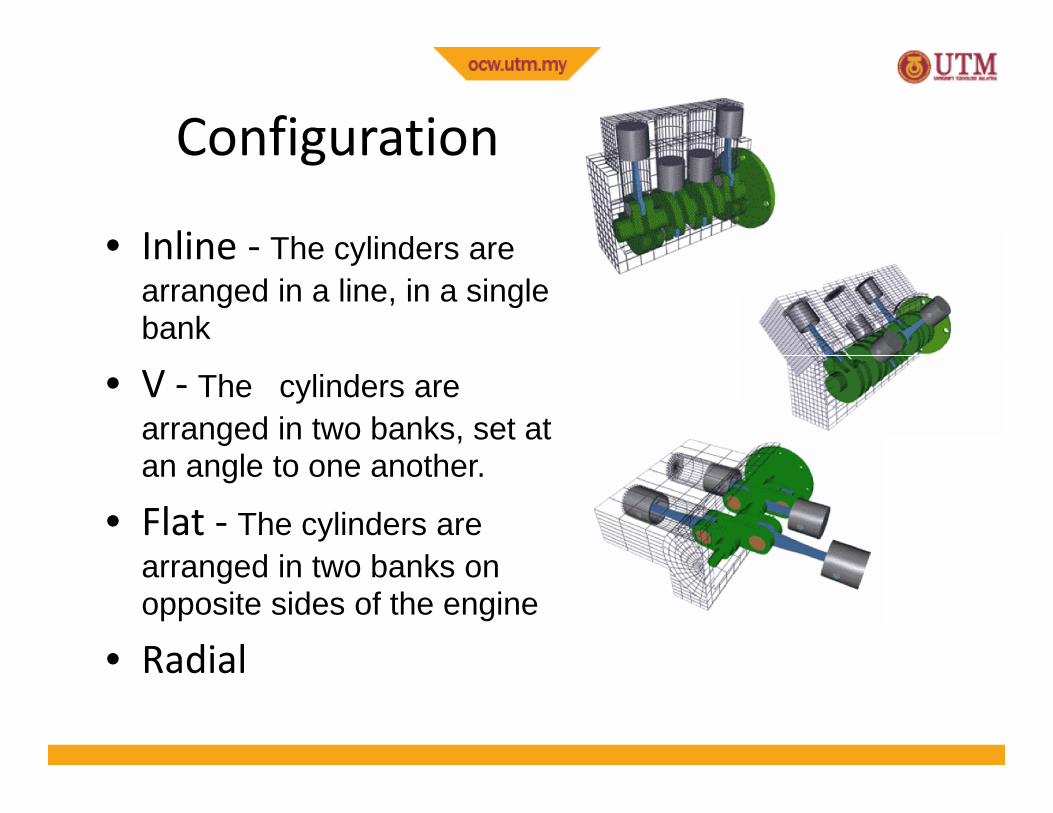
Configuration
• Inline - The cylinders arearranged in a line, in a singlebank
• V - The cylinders arearranged in two banks, set atan angle to one another.
• Flat - The cylinders arearranged in two banks onopposite sides of the engine
• Radial
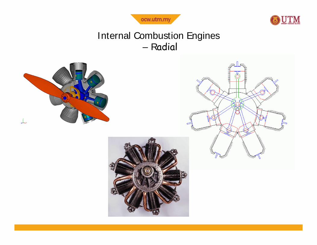
Internal Combustion Engines– Radial
V
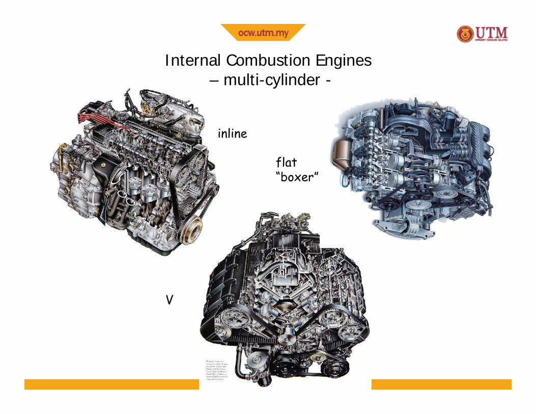
Internal Combustion Engines– multi-cylinder -
flat“boxer”
inline
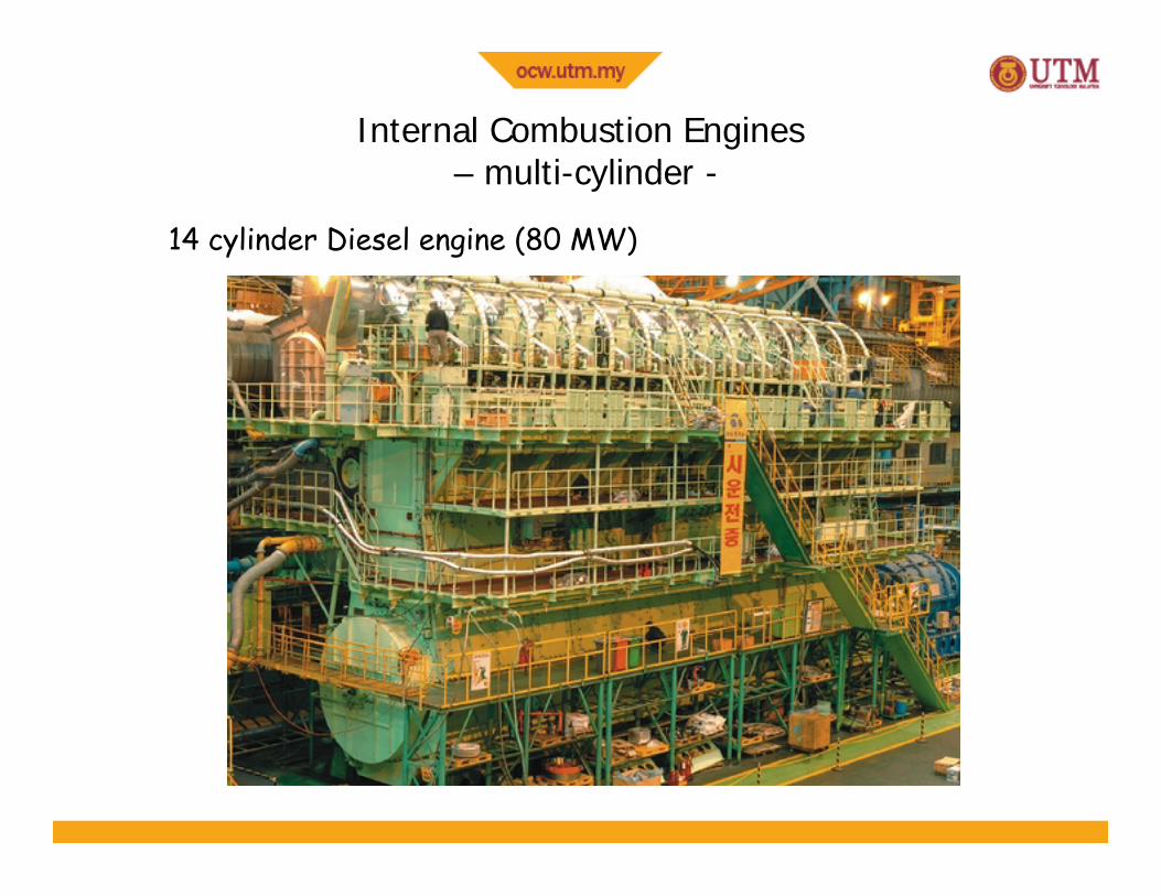
Internal Combustion Engines– multi-cylinder -
14 cylinder Diesel engine (80 MW)
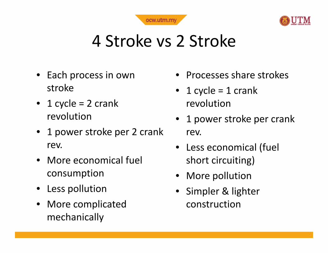
4 Stroke vs 2 Stroke
• Each process in ownstroke
• 1 cycle = 2 crankrevolution
• 1 power stroke per 2 crankrev.
• More economical fuelconsumption
• Less pollution• More complicated
mechanically
• Processes share strokes• 1 cycle = 1 crank
revolution• 1 power stroke per crank
rev.• Less economical (fuel
short circuiting)• More pollution• Simpler & lighter
construction
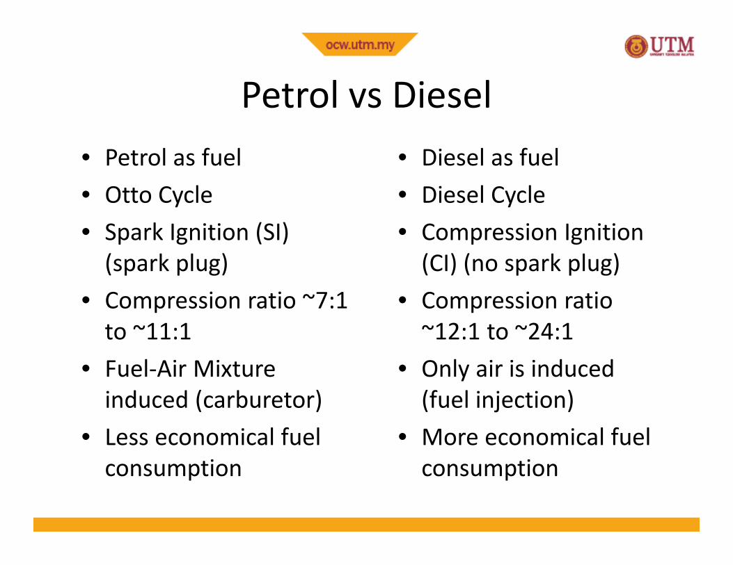
Petrol vs Diesel• Petrol as fuel• Otto Cycle• Spark Ignition (SI)
(spark plug)• Compression ratio ~7:1
to ~11:1• Fuel-Air Mixture
induced (carburetor)• Less economical fuel
consumption
• Diesel as fuel• Diesel Cycle• Compression Ignition
(CI) (no spark plug)• Compression ratio
~12:1 to ~24:1• Only air is induced
(fuel injection)• More economical fuel
consumption
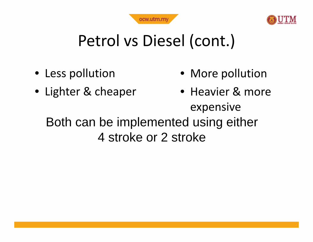
Petrol vs Diesel (cont.)
• Less pollution• Lighter & cheaper
• More pollution• Heavier & more
expensiveBoth can be implemented using either
4 stroke or 2 stroke
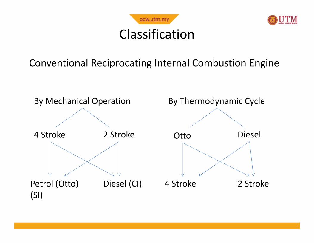
Classification
Conventional Reciprocating Internal Combustion Engine
By Mechanical Operation
4 Stroke 2 Stroke
Petrol (Otto)(SI)
Diesel (CI)
By Thermodynamic Cycle
Otto Diesel
4 Stroke 2 Stroke
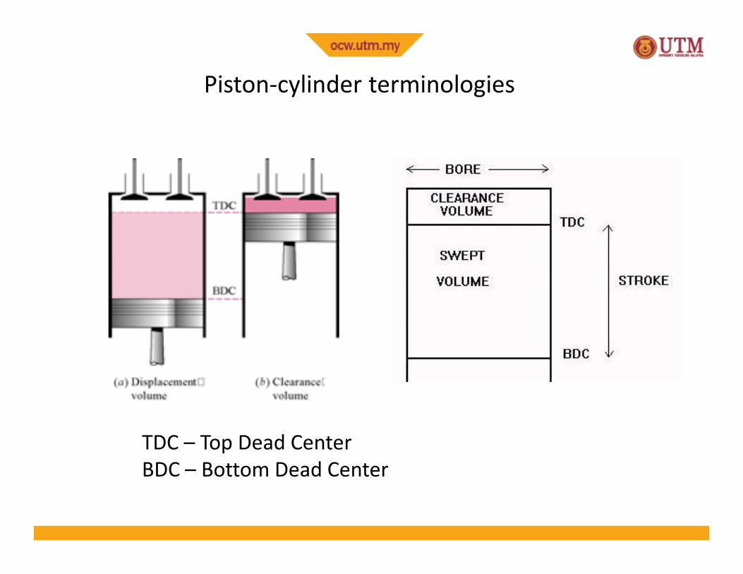
Piston-cylinder terminologies
TDC – Top Dead CenterBDC – Bottom Dead Center

b – Bore, Diameters – Strokel – Connecting Rod Lengtha – Crank Throw = ½ stroke
Piston-cylinder terminologies
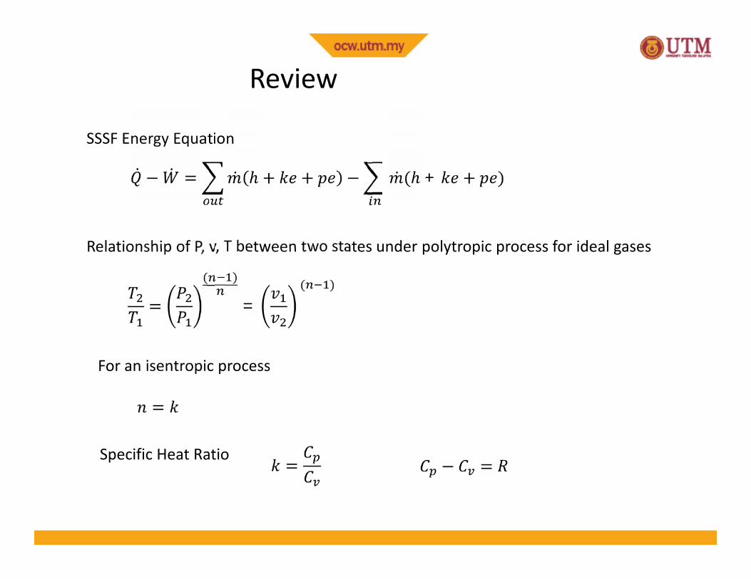
Review
SSSF Energy Equation
Relationship of P, v, T between two states under polytropic process for ideal gases
For an isentropic process
Specific Heat Ratio
− = + + − ( + + )
= ( ) = ( )
== − =
26
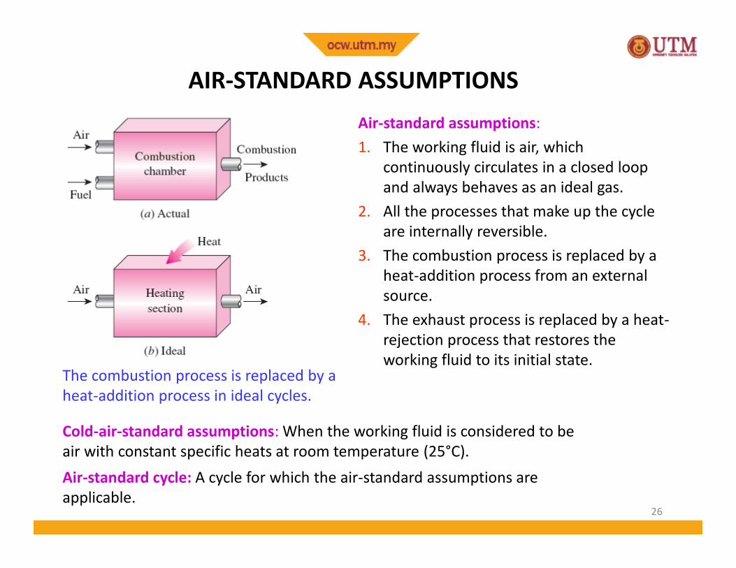
AIR-STANDARD ASSUMPTIONS
The combustion process is replaced by aheat-addition process in ideal cycles.
Air-standard assumptions:1. The working fluid is air, which
continuously circulates in a closed loopand always behaves as an ideal gas.
2. All the processes that make up the cycleare internally reversible.
3. The combustion process is replaced by aheat-addition process from an externalsource.
4. The exhaust process is replaced by a heat-rejection process that restores theworking fluid to its initial state.
Cold-air-standard assumptions: When the working fluid is considered to beair with constant specific heats at room temperature (25°C).Air-standard cycle: A cycle for which the air-standard assumptions areapplicable.
27
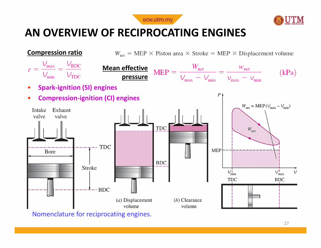
AN OVERVIEW OF RECIPROCATING ENGINES
Nomenclature for reciprocating engines.
• Spark-ignition (SI) engines• Compression-ignition (CI) engines
Compression ratio
Mean effectivepressure
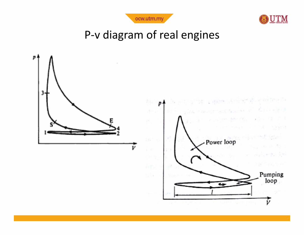
P-v diagram of real engines
29
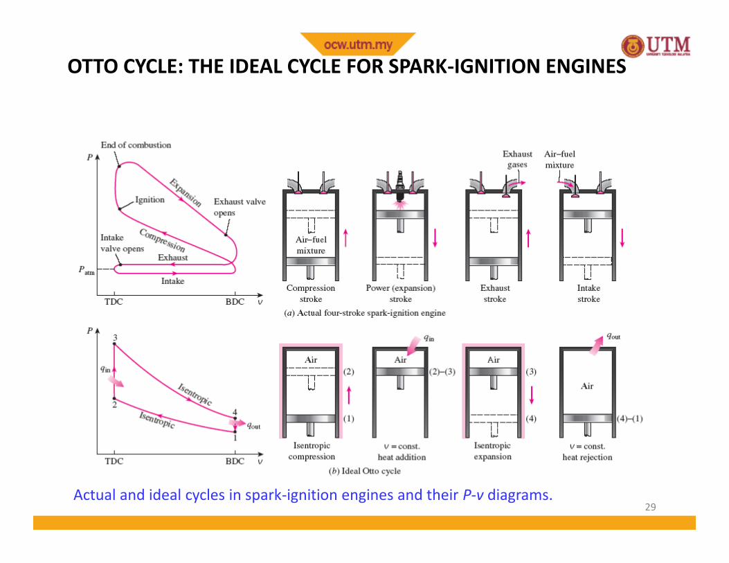
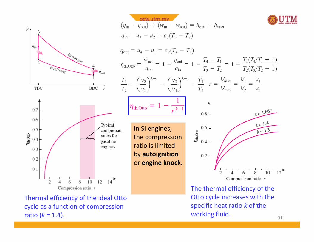
OTTO CYCLE: THE IDEAL CYCLE FOR SPARK-IGNITION ENGINES
Actual and ideal cycles in spark-ignition engines and their P-v diagrams.
30
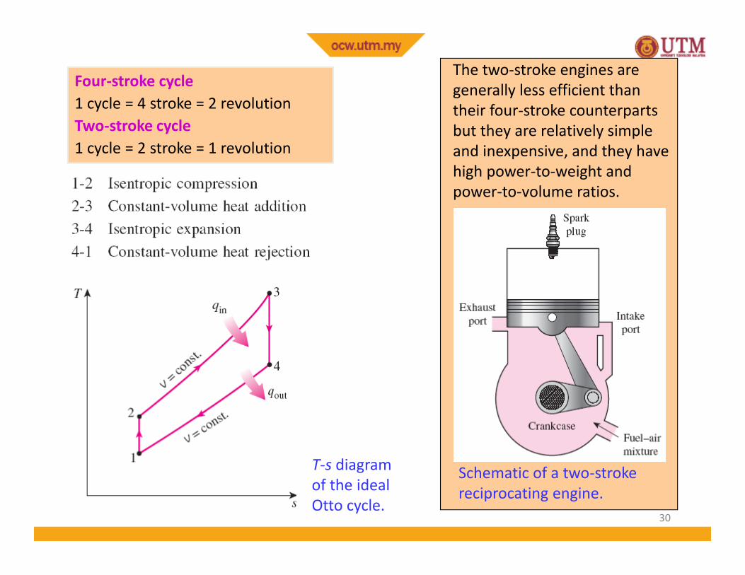
Schematic of a two-strokereciprocating engine.
The two-stroke engines aregenerally less efficient thantheir four-stroke counterpartsbut they are relatively simpleand inexpensive, and they havehigh power-to-weight andpower-to-volume ratios.
T-s diagramof the idealOtto cycle.
Four-stroke cycle1 cycle = 4 stroke = 2 revolutionTwo-stroke cycle1 cycle = 2 stroke = 1 revolution
31
The thermal efficiency of theOtto cycle increases with thespecific heat ratio k of theworking fluid.
Thermal efficiency of the ideal Ottocycle as a function of compressionratio (k = 1.4).
In SI engines,the compressionratio is limitedby autoignitionor engine knock.
32
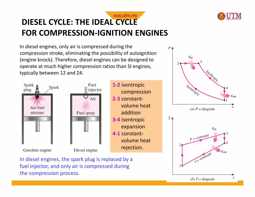
DIESEL CYCLE: THE IDEAL CYCLEFOR COMPRESSION-IGNITION ENGINES
In diesel engines, the spark plug is replaced by afuel injector, and only air is compressed duringthe compression process.
In diesel engines, only air is compressed during thecompression stroke, eliminating the possibility of autoignition(engine knock). Therefore, diesel engines can be designed tooperate at much higher compression ratios than SI engines,typically between 12 and 24.
1-2 isentropiccompression
2-3 constant-volume heataddition
3-4 isentropicexpansion
4-1 constant-volume heatrejection.
33
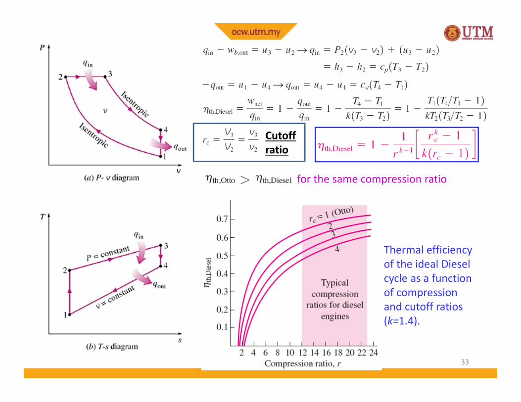
Thermal efficiencyof the ideal Dieselcycle as a functionof compressionand cutoff ratios(k=1.4).
Cutoffratio
for the same compression ratio
34
QUESTIONS ???
Diesel engines operate athigher air-fuel ratios thangasoline engines. Why?
Despite higher power toweight ratios, two-strokeengines are not used inautomobiles. Why?
The stationary diesel enginesare among the most efficientpower producing devices(about 50%). Why?
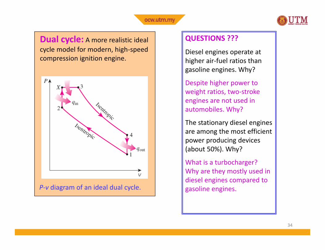
What is a turbocharger?Why are they mostly used indiesel engines compared togasoline engines.P-v diagram of an ideal dual cycle.
Dual cycle: A more realistic idealcycle model for modern, high-speedcompression ignition engine.
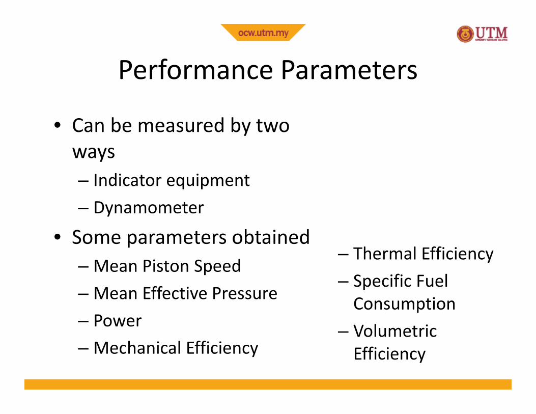
Performance Parameters
• Can be measured by twoways– Indicator equipment– Dynamometer
• Some parameters obtained– Mean Piston Speed– Mean Effective Pressure– Power– Mechanical Efficiency
– Thermal Efficiency– Specific Fuel
Consumption– Volumetric
Efficiency
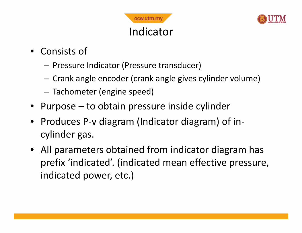
Indicator• Consists of
– Pressure Indicator (Pressure transducer)– Crank angle encoder (crank angle gives cylinder volume)– Tachometer (engine speed)
• Purpose – to obtain pressure inside cylinder• Produces P-v diagram (Indicator diagram) of in-
cylinder gas.• All parameters obtained from indicator diagram has
prefix ‘indicated’. (indicated mean effective pressure,indicated power, etc.)
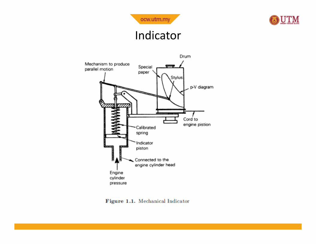
Indicator
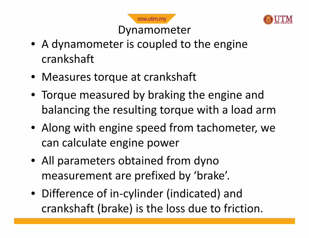
Dynamometer• A dynamometer is coupled to the engine
crankshaft• Measures torque at crankshaft• Torque measured by braking the engine and
balancing the resulting torque with a load arm• Along with engine speed from tachometer, we
can calculate engine power• All parameters obtained from dyno
measurement are prefixed by ‘brake’.• Difference of in-cylinder (indicated) and
crankshaft (brake) is the loss due to friction.
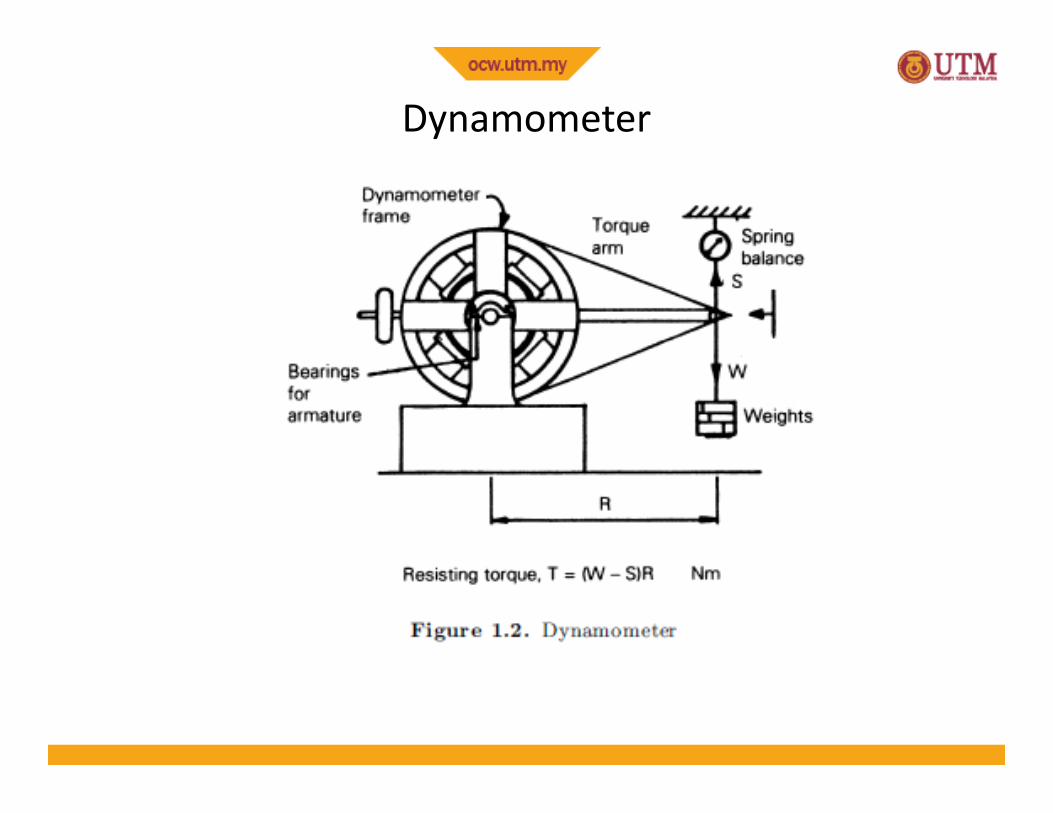
Dynamometer
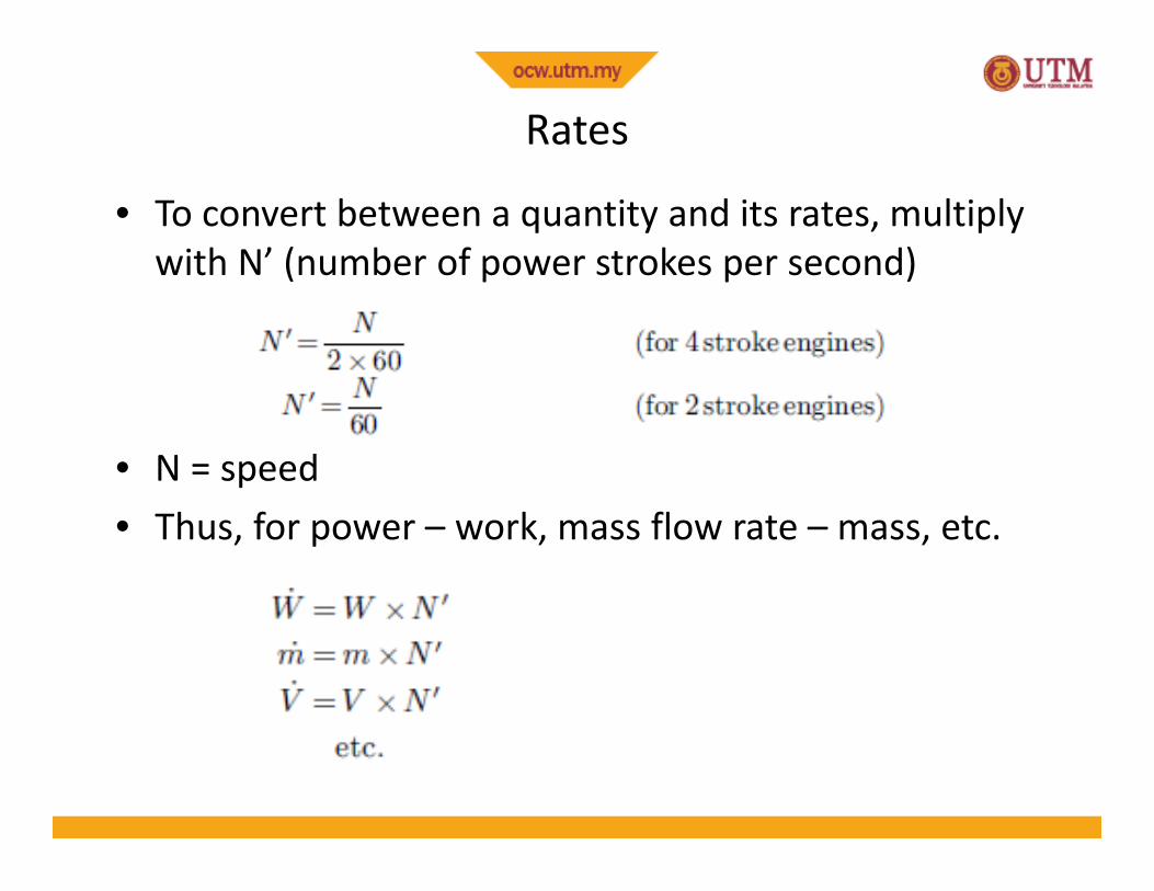
Rates
• To convert between a quantity and its rates, multiplywith N’ (number of power strokes per second)
• N = speed• Thus, for power – work, mass flow rate – mass, etc.
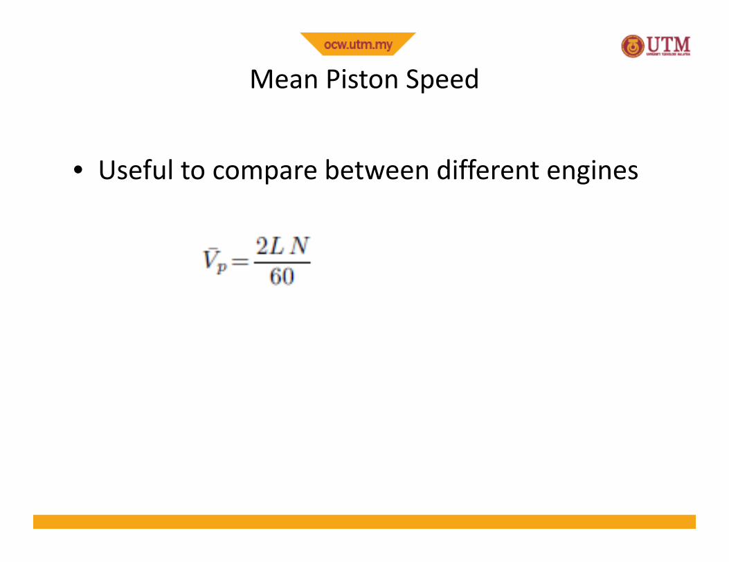
Mean Piston Speed
• Useful to compare between different engines
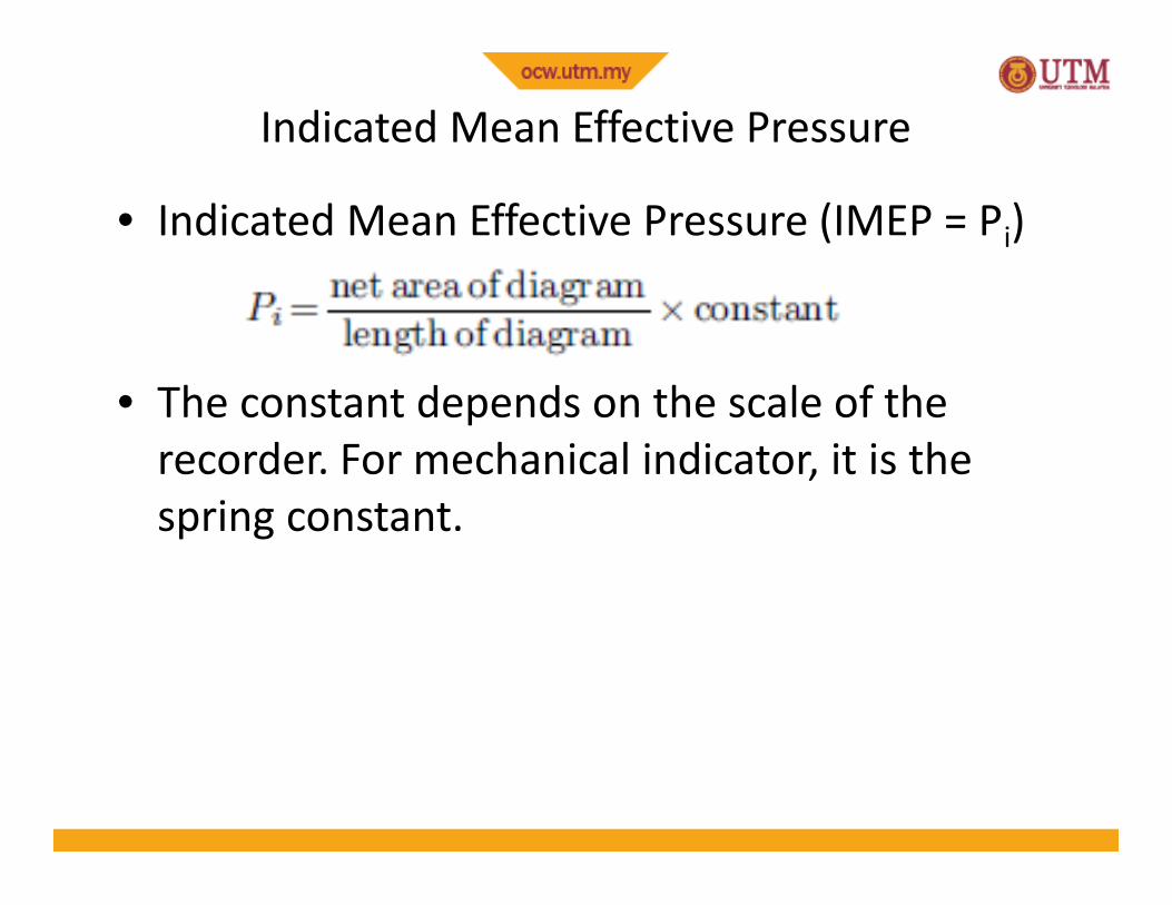
Indicated Mean Effective Pressure
• Indicated Mean Effective Pressure (IMEP = Pi)
• The constant depends on the scale of therecorder. For mechanical indicator, it is thespring constant.
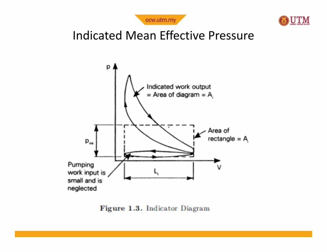
Indicated Mean Effective Pressure
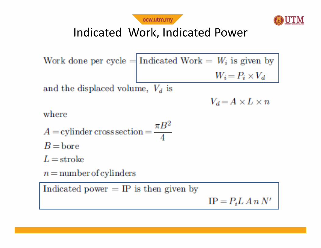
Indicated Work, Indicated Power

Brake Power
• From the dynamometer reading of torque
where W = dyno load, R = dyno arm length,• Brake Power (shaft power) is given by
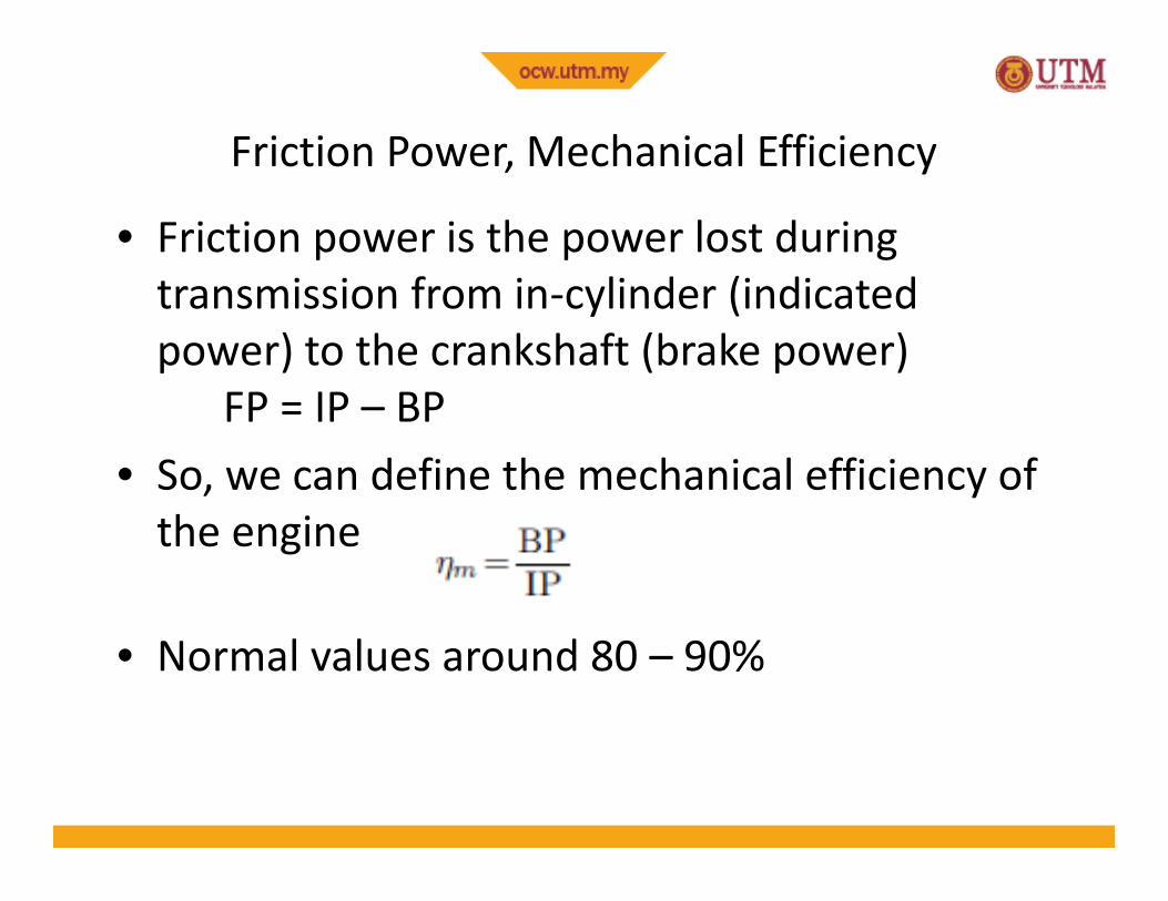
Friction Power, Mechanical Efficiency
• Friction power is the power lost duringtransmission from in-cylinder (indicatedpower) to the crankshaft (brake power)
FP = IP – BP• So, we can define the mechanical efficiency of
the engine
• Normal values around 80 – 90%
Brake Mean Effective Pressure (BMEP)
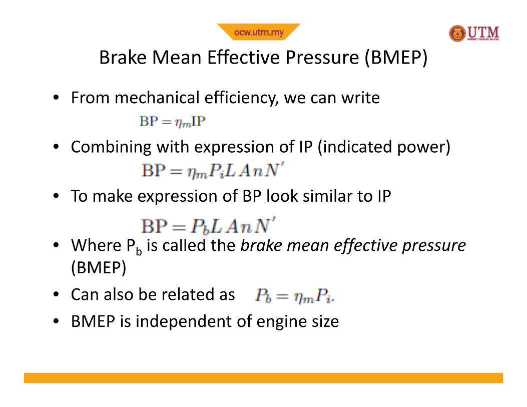
• From mechanical efficiency, we can write
• Combining with expression of IP (indicated power)
• To make expression of BP look similar to IP
• Where Pb is called the brake mean effective pressure(BMEP)
• Can also be related as• BMEP is independent of engine size
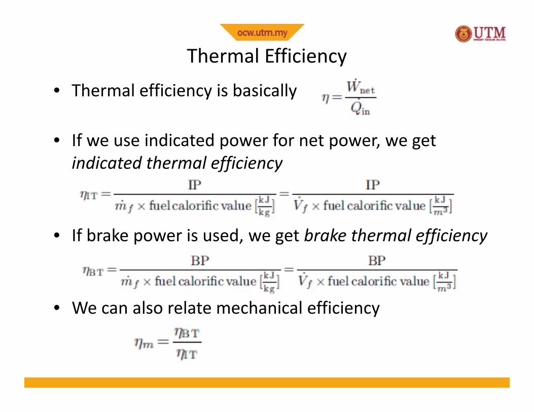
Thermal Efficiency• Thermal efficiency is basically
• If we use indicated power for net power, we getindicated thermal efficiency
• If brake power is used, we get brake thermal efficiency
• We can also relate mechanical efficiency
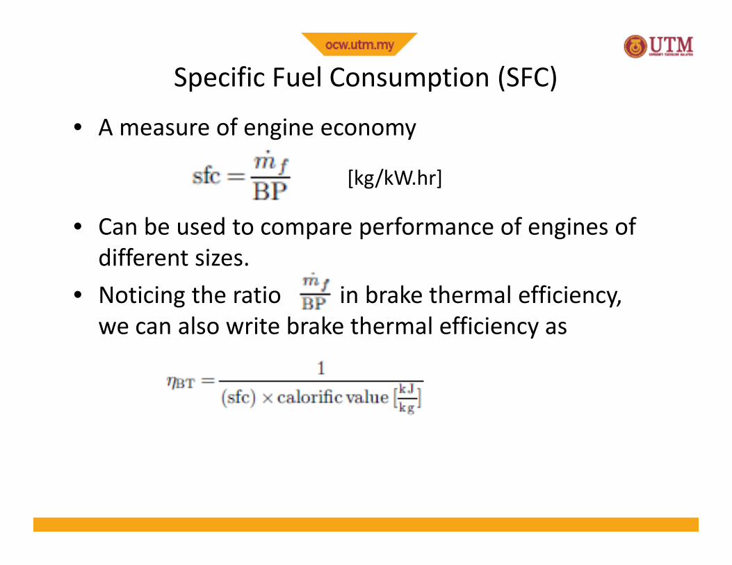
Specific Fuel Consumption (SFC)
• A measure of engine economy
• Can be used to compare performance of engines ofdifferent sizes.
• Noticing the ratio in brake thermal efficiency,we can also write brake thermal efficiency as
[kg/kW.hr]
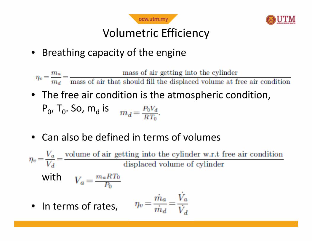
Volumetric Efficiency• Breathing capacity of the engine
• The free air condition is the atmospheric condition,P0, T0. So, md is
• Can also be defined in terms of volumes
with
• In terms of rates,