Embed Size (px)
Citation preview
Thermoforming QUArTerLY 1WWW.THERMOFORMINGDIVISION.COM
Quarterly ®
Thermoforming
NSIDE …I
A JOURNAL OF THE THERMOFORMING DIVISION OF THE SOCIETY OF PLASTIC ENGINEERS FOURTH QUARTER 2012 n VOLUME 31 n NUMBER 4
®
Post Conference Edition
The Business of Thermoforming: Industrial Investments pages 10-13
ANTEC Paper: Liquid Crystal Polymer pages 14-18
2012 Conference Review page 20
Wrapping Up 2012 in Style
2 Thermoforming QUArTerLY
Thermoforming QUArTerLY 1
A JOURNAL PUBLISHED EACH CALENDAR QUARTER BY THE THERMOFORMING DIVISION
OF THE SOCIETY OF PLASTICS ENGINEERS
EditorConor Carlin(617) 771-3321
SponsorshipsLaura Pichon(847) 829-8124
Fax (815) [email protected]
Conference CoordinatorLesley Kyle
(914) [email protected]
Thermoforming Division Executive Assistant
Gwen Mathis(706) 235-9298
Fax (706) [email protected]
Thermoforming Quarterly® is pub-lished four times annually as an infor-mational and educational bulletin to the members of the Society of Plastics Engineers, Thermoforming Division, and the thermoforming industry. The name, “Thermoforming Quarterly®” and its logotype, are registered trademarks of the Thermoforming Division of the Society of Plastics Engineers, Inc. No part of this publication may be reproduced in any form or by any means without prior writ-ten permission of the publisher, copyright holder. Opinions of the authors are their own, and the publishers cannot be held responsible for opinions or representa-tions of any unsolicited material. Printed in the U.S.A.
Thermoforming Quarterly® is registered in the U.S. Patent and Trademark Office (Registration no. 2,229,747). x
ThermoformingQuarterly®
ThermoformingQuarterly®
FOURTH QUARTER 2012VOLUME 31 n NUMBER 4
Contents
n DepartmentsChairman’s Corner x 2
Thermoforming in the News x 4
University News x 26
n In This IssueGwen Mathis Named Emeritus Director x 7
2012 Conference x 24
In Memoriam - Bill Benjamin x 27
2012 Parts Competition Winners x 28-29
Sponsorships x 36
www.thermoformingdivision.com
Page 20
n Features
The Business of Thermoforming x 10-13Understanding Industrial Investment Decision-Making
ANTEC Paper x 14-18Thermoformable Liquid Crystal Polymer (LCP)
Industry Practice x 20SPE Thermoforming Division’s 21st Annual Conference Report
Industry Practice x 21Thermoforming Continues to Create Job Opportunities
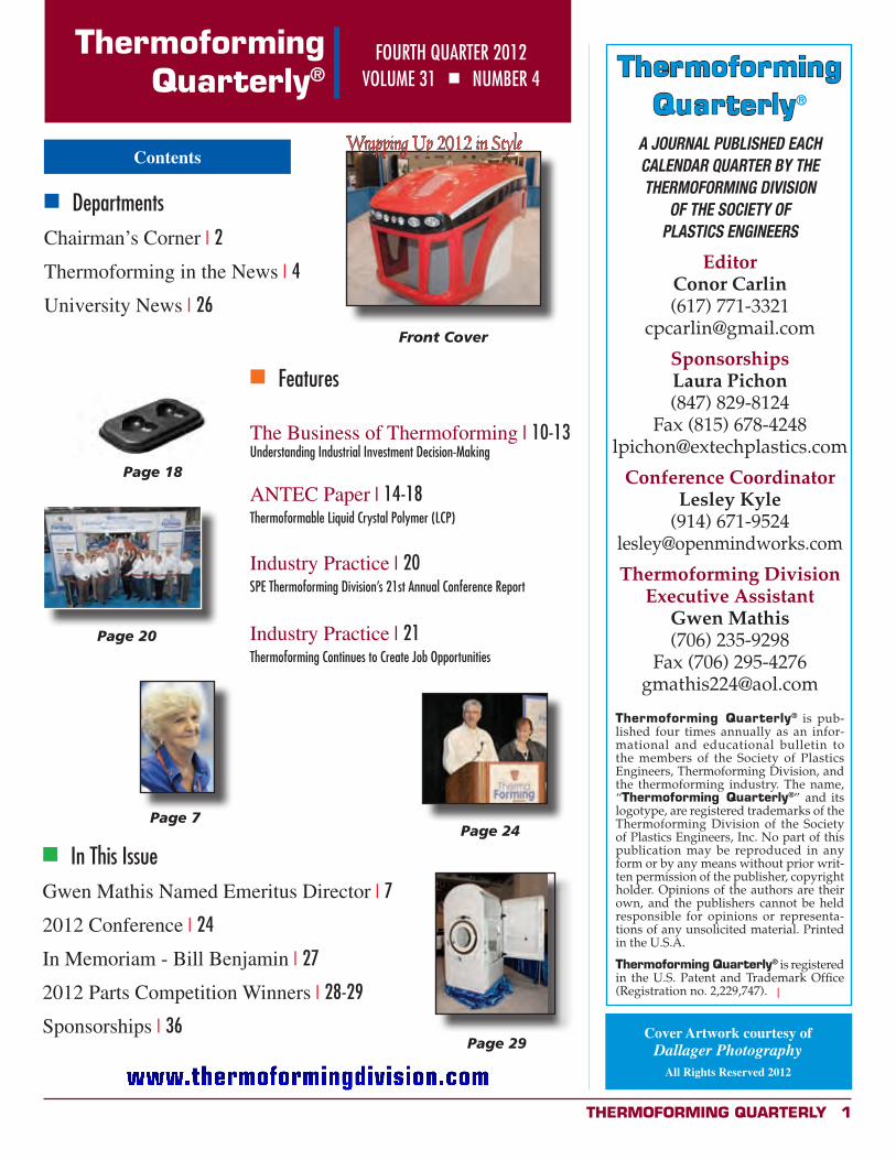
Front Cover
Cover Artwork courtesy ofDallager Photography
All Rights Reserved 2012
Page 18
Page 24
Page 29
melt strength can be formed but will exhibit thickness variation and wall thinning. Crystalline materials lose melt strength and melt elasticity above their peak melting point. Crystalline materials also require a lot higher energy to heat but a amorphous materials. Generally, amorphous polymers have a wider forming process temperature range than crystalline polymers. LCP has small heat transition, which means it is heated fast in heating stage and cooled rapidly during forming stage.
As shown in Table 4, good uniform shapes were
formed in Run 1, 3 and 4. For Run 2, some holes were formed around thin neck, which indicated that an over-drawing ratio caused breakages. This breakage may relate to two factors: one is fast decrease of form temperature, another is strain hardening. Overall, forming temperatures around 320-340o C offer a good forming window.
To further verify the melt elasticity, vacuum forming
without a plug on pre-heated samples was tested. Vacuum forming is a very rapid process. Figure 10 shows a vacuum formed sample. It has good, even thickness in the bulb and there is no hole/breakage, which indicates that the TF-LCP has excellent melt elasticity.
F igure 10. Vacuum forming sample
Thermoformable LCP sheets were also formed at commercial thermoforming units. Figure 11 shows an example of a heart shape tray, and Figure 12 shows an example of a baking tray.
F igure 11. Chocolate heart shape form tray by thermoformable L CP
F igure 12. Baking tray by thermoformable L CP
Conclusions
Thermoformable LCP shows very high melt viscosity and high heat deflection temperature. It can be extruded into sheets for thermoforming. Due to its unique melt transition, compared with semi-crystalline or amorphous polymers, thermoformable LCP resin needs special processing conditions for extruding quality sheets and forming good parts. For TF-LCP discussed in this paper, the sheet extrusion melt temperature is about 345-360oC and the forming temperature range is about 320-340oC. The TF-LCP has good melt strength and elasticity based on thermoformability tests. Due to its rapid heating and cooling characteristics, special means for heat retention is needed during forming. Vacuum forming is preferred because of fast forming cycle and minimum heat loss.
References 1.
01) 2. th Ed.,
Hanser Gardner (2001 3.
Hanser Verlag (1996) 4. M. Mogilevsky, Polymer Engineering and Science,
Vol. 38, 322-329 (1998)
30 mm
Wrapping Up 2012 in Style
Page 7
2 Thermoforming QUArTerLY
ThermoformingQuarterly® Chairman’s Corner
Phi
l Bar
hous
e Looking Backat 2012
I enjoyed seeing all of you at our 21st Annual
Thermoforming Conference in Grand Rapids. For those of you who did not attend, you missed an excellent conference. You can read all about it in the Conference Wrap-Up Report and see the Parts Competition winners in this issue. I would like to thank our Conference Chairs, Haydn Forward and Lola Carere, and their entire committee for the outstanding work with this conference.
Next year’s conference will be hosted in Atlanta, so mark your calendars for September 9 -12. We have recently revised this date to avoid conflicts with other industry events; so please check the website for further details.
On behalf of the Board of Directors, I wish to express my deepest sympathy to
the Benjamin family on
the passing of Mr. Bill
Benjamin. Bill was President
of Benjamin Manufacturing
Company that he and his
wife Beverly started in 1961
(see page 27). Bill was a true
pioneer in the industry and
was a huge supporter of this
Division for many years. He
was named Thermoformer
of the Year in 2003 and
continued to attend board
meetings up until very
recently. I will personally miss
his warm friendly smile, the
advice and the guidance that
he gave me over the years. He
will be greatly missed.
On page 9, you will find the
form and nomination criteria
for the 2013 Thermoformer
of the Year. This is the
highest award that the
Board presents. Please help
us by identifying worthy
candidates. This prestigious
honor will be awarded to an
individual who has made
significant contributions to
the thermoforming industry
in a technical, educational, or
managerial aspect capacity.
Nominees will be evaluated
prior to voting by the Board of
Directors at the February 2013
board meeting. Each of us in
the thermoforming industry
knows at least one person
whose contributions deserve
to be recognized in front of
their peers. Please feel free to
contact me or another board
member if you have questions
about this award.
As always, I would like to
hear your ideas, comments
and feedback. x
Phil Barhouse
Thermoforming QUArTerLY 3
Are You
http://www.linked.com/groups?gid=3992496&trk=myg
ugrp ovr
Group Name:Thermoforming Division,
a subgroup of SPE
Moderator:Mark Strachan
Trending Topics(as of November 28, 2012)
1. Material selection: PP vs HIPS for yogurt cups
2. Machinery options for producing cups and lids
With over 380 members
and growing, the
Thermoforming Division is
using Linkedin to expand
the conversation. Meet
fellow professionals,
ask tough technical
questions, explore
related groups.
Join us today!
4 Thermoforming QUArTerLY
ThermoformingQuarterly® New Members
Pierre AlbertynPolytechCape Town
Ed AndersonDistinctive MoldsHenderson, CO
John AnthonyAndexEscanaba, MI
Erasmo AvilaImpersealco S.A. de C.V.Tultitlan, Estado de México
Hermes AzzoMidwest Exchange Inc.Gurnee, IL
Troy BeemanACI PlasticsKansas City, MO
Beverly BejaminBenjamin Mfg.Bellflower, CA
Ray BergBushwacker, Inc.Portland, OR
Kristen BoardGE AppliancesLouisville, KY
David A. BranscombJohn Deere Technology CenterDubuque, IA
LeBron BrightVeluxGreenwood, SC
C. Matthew BrownPoly Flex Products, Inc.Farmington Hills, MI
Rich CamachoAmerichem, Inc.Elgin, IL
Michael CameronKlockner PentaplastSylvania, OH
Tony D. CentrittoCraft Originators, Inc.Hamilton, Ontario
Shawn Andrew ChisholmNeocon InternationalDartmouth, Nova Scotia
Anne-Marie ChronasNu-B Inc.St. Laurent, QC
Tawnya Suzanne ClarkGE AppliancesLouisville, KY
Matt ConwayACI PlasticsKansas City, MO
Jay CoventryBoltaronDover, OH
Sam CultronaPlastics Machinery GroupSolon, OH
Caroline D’AllardStyl’MondePont D’Ain
Natalie DeGraceuVu TechnologiesBoca Raton, FL
Wesley J. DistefanoCreative FoamFenton, MI
Medhi M. EmadArkema Inc.King of Prussia, PA
Tim FeltonPlastic IngenuityMaumelle, AR
Kate M. QuigleyState GardenChelsea, MA
Zvi RapaportBushwacherPortland, OR
John RhoadesPlaconFitchburg, WI
Rick RialPlas-Tech Thermoforming Ltd.Brandesburton, East Yorks
Kevin Andrew RichardsonDeltaformBridgewater, Somerset
Ben RidleyFormit ServicesFountaindale, NSW
Bob RindoHampel Corp.Germantown, WI
Daniel C. RobinsonPLI Inc.Suwanee, GA
Yugi RyoshoMytex PolymersJeffersonville, IN
Deepa SamkuttyArlington, TX
Bill SchneiderMonark-EquipmentAuburn, MI
Steven SchulzeIndustrial RecyclersSidney, OH
Leon E. SheridanCrown PlasticFestus, MO
Craig SmithCPS Resources Inc.Indian Trail, NC
Matt StadtmuellerBemisNeenah, WI
Michael StaelgraeveDandy Pkg. Inc.Monroe, MI
Ronald StaubSay Plastics Inc.McSherrystown, PA
Jack L. SubelThe Fabri-Form Co.New Concord, OH
John SugdenThe Dow Chemical Co.Midland, MI
Nik TaritasKydex LLCBartlett, IL
Barry TaylorConcote Corp.Coppell, TX
Nick ThonDart ContainerLansing, MI
Thomas TodebushBrueckner Group USAWarren, MI
Carol Trier-BlackSC JohnsonBay City, MI
Tom Van NortwickInnovative Plastech, Inc.Batavia, IL
Anne WalkerNova ChemicalsMonaca, PA
Katie M. WaznySC JohnsonBay City, MI
Rick ForbisBattenfeld CincinnatiMint Hill, NC
Jason Froesethink4DAltona, MBDiego GaravitoCarvajal EmpaquesCali, Valle
Farzad GhodsCarburesGreenville, SC
Eric GivensHampel Corp.Germantown, WI
Tim GoinsAmerican AirlinesTulsa, OK
Martijn HaexBosch Sprang BVSprang-Capelle
Timothy J. HagueProcter and GambleCincinnati, OH
Jack HamerAcrofab, Inc.Zeeland, MI
Allan HarrisDraderEdmonton, AB
Heather HawkMAAC MachineryCarol Stream, IL
Michael HaynieVeluxGreenwood, SC
Brent Allen Hedding3M Co.St. Paul, MN
Allen HendrixHeritage PlasticsFairmount, GA
Thermoforming QUArTerLY 5
ThermoformingQuarterly® New Members (continued)
Paul D. HickeyAuburn Vacuum Forming Co.Auburn, NY
Amr HosnyBariQ-A Raya Holding SubsidiaryGiza
Andrew HuntPlastic IngenuityMaumelle, AR
Michael W. IrvinSchutt Sports Mfg. Co.Salem, IL
Rocky JacobsConcote Corp.Tyler, TX
Michael David JoudreyGN Thermoforming EquipmentChester, Nova Scotia
Jaime Arturo JuliaoPropilcoBogota, Cundinamarca
James KarnesCrown PlasticsFestus, MO
Steve KastnerVelux GreenwoodGreenwood, SC
Nancy KiefferPlastics Unlimited Inc.Preston, IA
Chris KirbyCreative Foam Corp.Granger, IN
Andrew K. KitsonGDC, Inc.Goshen, IN
Rex KnechtlyMcClarin Plastics, Inc.Hanover, PA
Jared KorrecktWNAChattanooga, TN
Steve KoskiDraderEdmonton, AB
Dan KosterCreative PlasticsGrand Haven, MI
Jay KumarUniversal PlasticsHolyoke, MA
Rhys Lewis-SmithFormit ServicesBellevue Hill, NSW
Tony Y-Tsen LoWestern Michigan UniversityPortage, MI
Jared LorensonDisplay PackGrand Rapids, MI
Michael MacDonaldODC Tooling and MoldsWaterloo, Ontario
Martin MaillouxPlastique ArtSte-Claire, Quebec
Luke McCarronGN Thermoforming EquipmentChester, NS
Dale Edward McCarthyYescoLas Vegas, NV
Michael McConnaghyOMV-USAElkhorn, WI
Brian McFadyenCraft Originators Inc.Hamilton, Ontario
Robert McNealNcNeal EnterprisesSan Jose, CA
Nick MellentuinPlastic IngenityMaumelle, AR
Adam MelvilleFormit ServicesFountaindale, NSW
Michael MillerBellingham, WA
Ken MinerACI PlasticsKansas City, MO
Natalie MoormanCarol Stream, IL
Jason NewmanBrown MachineBeaverton, MI
Scott W. NiedzwieckiSonoco Protective PackagingDekalb, IL
Ted OwenMSA Components, Inc.Cincinnati, OH
Jeremy PhillipsMinimizerBlooming Prairie, MN
Michael John PolanskyInnovative Plastech Inc.Batavia, IL
Andrew WebbInsul-Fab, Div. of Concote Corp.Coppell, TX
Joe WeberHampelGermantown, WI
Marjorie WeinerSociety of Plastics EngineersBrooklyn, CT
Andrew WiessVantage PlasticsStandish, MI
Dan WilliamsPlacon Corp.Madison, WI
Mark WilsonPlas-Tech Thermoforming Ltd.Brandesburton, East Yorkshire
Kyle Thomas WrightClifton Park, NY
Wes YandtMultifab Inc.Spokane Vly, WA
Robert W. ZachrichThe Fabri-Form Co.New Concord, OH
Lincoln ZevallosPlastic Package Inc.Sacramento, CA
Why Join?
WhyNot?
I t has never been more
important to be a member of
your professional society than
now, in the current climate of
change and volatility in the
plastics industry. Now, more
than ever, the information
you access and the personal
networks you create can and
will directly impact your future
and your career.
Active membership in SPE
– keeps you current, keeps
you informed, and keeps you
connected.
The question really isn’t “why join?”
but …
6 Thermoforming QUArTerLY
Thermoforming in the news
Plastic Ingenuity Buys Vitalo de Mexico AssetsBy Jessica Holbrook, Plastics News StaffPosted October 17, 2012MONTERREY, MEXICO (4:35 p.m. ET)
Danish thermoformer Faerch Plast A/S is developing
a type of crystalline PET that can be detected by infra red technology in recycling streams, meaning the material can be separated from mixed plastics waste.
“When recycling plastics, companies have infra red
Plastic Ingenuity de Mexico, an affiliate of Plastic
Ingenuity Inc., has purchased the assets of thermoformed packaging producer Vitalo de Mexico.
The acquisition allows Plastic Ingenuity to boost capacity and capabilities, as well as expand operations – the company will now operate two plants in Monterrey, Mexico, along with Vitalo de Mexico’s facilities in Guadalupe, Nuevo León.
It also allows the company to “capitalize on the return of manufacturing business to North America from Asia,” said Tom Kuehn, president of Plastic Ingenuity, in a news release.
Vitalo de Mexico is a branch of Belgium thermoforming giant the Vitalo Group.
Terms of the deal were not disclosed.
Plastic Ingenuity de Mexico was formed in 2006 through a joint venture between Plastic Ingenuity and Converforma
of Monterrey. Prior to the acquisition, the company operated eight vacuum forming lines at its Monterrey plant.
Based in Cross Plains, Wisconsin, Plastic Ingenuity makes custom thermoformed packaging for a variety of markets including food, medical, electronics and retail. The company has approximately 500 employees, and operates 11 extrusion lines and 46 thermoforming lines across its four U.S. locations.
Plastic Ingenuity had sales of $80 million in 2012 and was No. 24 in the most recent Plastics News ranking of North American thermoformers. x
Faerch Plast Tests Recyclable Black CPETBy Charlotte Eyre, European Plastics News StaffPosted October 30, 2012HOLSTEBRO, DENMARK (1:45 p.m. ET)
cameras to identify what the plastics are,” spokesman Joe Iannidinardo told European Plastics News. “But when the plastic is black light can’t shine through it, meaning it can’t be detected by the cameras.”
Faerch Plast has reformulated its CPET material with a different pigment arrangement. This allows some of the infra red light to reflect back into the cameras, meaning the material can be recycled in mixed waste streams.
The company developed the material at its R&D center in Denmark but is currently testing using the material to manufacture trays for ready meals in the UK, which is the main market for these products. The firm is now carrying out tests with stakeholders, including WRAP and various supermarkets.
“We’re excited about the project because it brings the idea of a closed loop system closer and closer,” said Iannidinardo, adding: “The aim is to have the trays come back to use as flakes, perhaps even three or four times.”
Iannidinardo did not go into detail about how Faerch Plast plans to manufacture the material but says the company aims to make the process “cost neutral” compared to other materials on the market. x

Thermoforming QUArTerLY 7
Become aThermoforming
Quarterly Sponsorin 2013!
Additional sponsorship opportunities will include
4-color, full page, and 1/2 page.
RESERVE YOUR PRIME SPONSORSHIPSPACE TODAY.
Questions? Call or emailLaura Pichon
Ex-Tech Plastics847-829-8124
BOOK SPACEIN 2013!
2013EDITORIALCALENDAR
Quarterly Deadlines forCopy and Sponsorships
ALL FINAL COPY FOR EDITORIAL APPROVAL
15-FEB Spring 30-APR Summer
31-JUL Fall 15-NOV WinterConference Edition Post-Conference Edition
All artwork to be sent in .eps or .jpg format with minimum
300dpi resolution.
Gwen Mathis Named Emeritus DirectorIn recognition of her years of dedicated service to the SPE Thermoforming Division and the industry at large, Gwen Mathis was named Emeritus Director, Board of Directors, Thermoforming Division.
Emeritus Director status replaces current board member status and has a term of three years. Emeritus Directors can
be involved in all board activities including conference preparation and involvement with technical committees. Emeritus Directors continue to receive quarterly newsletters and all other Board of Director announcements and emails. They are not required to attend board meetings and do not have voting responsibilities. Emeritus members are encouraged to be members of the Society of Plastics Engineers (SPE). Qualified candidates are recommended through the Membership Committee and brought to the attention of the Executive Committee for consideration and approval. x
8 Thermoforming QUArTerLY
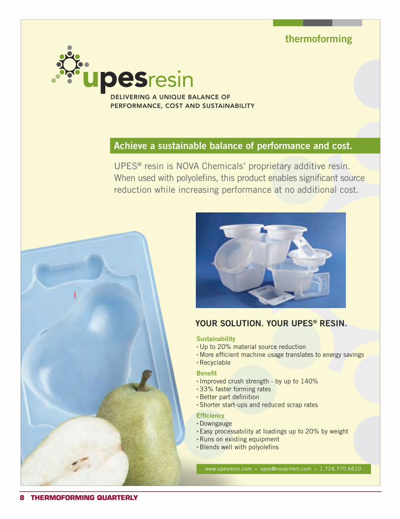
Achieve a sustainable balance of performance and cost.
thermoforming
UPES® resin is NOVA Chemicals’ proprietary additive resin. When used with polyolefins, this product enables significant source reduction while increasing performance at no additional cost.
Sustainability• Up to 20% material source reduction• More efficient machine usage translates to energy savings• Recyclable
Benefit• Improved crush strength - by up to 140%• 33% faster forming rates• Better part definition• Shorter start-ups and reduced scrap rates
Efficiency• Downgauge• Easy processability at loadings up to 20% by weight• Runs on existing equipment• Blends well with polyolefins
YOUR SOLUTION. YOUR UPES® RESIN.
www.upesresin.com • [email protected] • 1.724.770.6610
x
Thermoforming QUArTerLY 9
Thermoformer of the Year 2013
The Awards Committee is now accepting nominations for the 2013 THERMOFORMER OF THE YEAR. Please help us by identifying worthy candidates. This prestigious honor will be awarded to a member of our industry who has made a significant contribution to the thermoforming industry in a technical, educational, or managerial aspect of thermoforming. Nominees will be evaluated and voted on by the Thermoforming Board of Directors at the Winter 2013 meeting. The deadline for submitting nominations is January 15th, 2013. Please complete the form below and include all biographical information. Total submission, including this application page, must not exceed four (4) pages.
Person Nominated: ____________________________________ Title: ___________________
Firm or Institution______________________________________________________________
Street Address: ____________________________ City, State, Zip: ______________________
Telephone: _______________ Fax: _________________ E-mail: ________________________ Biographical Information:
• Nominee’s Experience in the Thermoforming Industry.• Nominee’s Education (include degrees, year granted, name and location of university)• Prior corporate or academic affiliations (include company and/or institutions, title, and
approximate dates of affiliations)• Professional society affiliations• Professional honors and awards.• Publications and patents (please attach list).• Evaluation of the effect of this individual’s achievement on technology and progress of
the plastics industry. (To support nomination, attach substantial documentation of these achievements.)
• Other significant accomplishments in the field of plastics.
Individual Submitting Nomination: _______________________ Title: _____________________
Firm or Institution______________________________________________________________
Address: __________________________________ City, State, Zip: ______________________
Phone: _______________ Fax: _________________ E-mail: ___________________________
Signature: ___________________________________________ Date: ____________________
(ALL NOMINATIONS MUST BE SIGNED)
Please submit all nominations to: Juliet Goff,Kal Plastics,
2050 East 48th Street, Vernon CA 90058-2022Phone 323.581.6194, ext. 223 or email at: [email protected]
10 Thermoforming QUArTerLY
ThermoformingQuarterly® The Business of Thermoforming
Understanding Industrial Investment Decision-Making
By Christopher Russell and Rachel Young,American Council for an Energy Efficient Economy
Editor’s Note: The following excerpts are reprinted with permission from the American Council for an Energy Efficient Economy (ACEEE). We offer this synopsis to our readers because the report has broad implications for thermoforming OEMs, processors, suppliers and toolmakers surrounding capital and operational investments. The complete report includes in-depth survey results from NAICS-coded industrial sectors, including plastics (326). Please visit www.aceee.org for more details.
Executive Summary
After a prolonged recession, the U.S. economy is poised for recovery. Economic rebound implies growth and renewal to accompany the ongoing evolution of energy markets, regulations, and technologies. And because manufacturing is by nature a capital-intensive activity, we anticipate that the sector’s economic renewal is partially dependent on capital investment in new and efficient technologies. Industrial energy efficiency opportunities coincide with economic recovery and the growth and modernization of domestic production capacity.
Economic recovery prospects across the manufacturing sector are stronger for some industries than for others. As the manufacturing sector changes, so should the nature of energy efficiency programs. Industry’s motivation for achieving energy improvements still lags its true potential, as the propensity to adopt energy management principles remains irregular, even across facilities of the
same company. As facilities continues to capture many of the low- and no-cost energy improvement opportunities, future improvements will be increasingly linked to industry’s capital investment activity. Industrial energy program administrators will need a better understanding of capital investment processes as these vary throughout industry. By influencing capital investment decisions, the next generation of energy efficiency programs can influence the profile of industrial energy use for years to come. Despite a decade of sluggish economic growth (2000-2009), output and productivity data from 1998-2009 reveal an industrial sector with elements of growth, recuperation, and surprisingly little retrenchment. Productivity gains achieved by many industries during this decade despite their low growth of output are evidence of the muscle needed for an economic rebound, while capacity utilization
and investment rates point to opportunities for industrial expansion.
Introduction
In 2012, the U.S. economy is poised for recovery from a prolonged recession. Aiding the recovery is the trend of re-shoring of industrial production facilities from overseas locations (MAPI 2012, BCG 2012). Recovery will in part reflect capital investment in new and more efficient manufacturing facilities on U.S. soil. At the core of this activity is capital investment in industrial assets. Investment in durable facility and production assets will shape industrial energy intensity for years to come. This is an opportunity to evolve and intensify industrial energy efficiency programs to support the implementation of efficient technologies. Successful industrial energy programs will increasingly depend on knowledge of industry’s capital investment decision-making process. This report examines
Thermoforming QUArTerLY 11
(continued on next page)
industrial capital investment experience, using macroeconomic data as well as a survey of industrial energy users and related market and program facilitators.1 The findings suggest an evolution of energy program design and conduct.
Trends in manufacturing output have direct implications for the national economy on three broad dimensions. First, while U.S. manufacturing output is decreasing as a proportion of total GDP, the absolute volume of manufacturing output is still increasing. This simply means that manufacturing as a whole is not growing as quickly as some other sectors (Pollack 2012). Still, each dollar of manufacturing output also generates an additional $1.40 worth of non-manufacturing services throughout the domestic economy (NAM 2009). Second, the industrial sector represents 31 percent of all domestic energy consumption (EIA 2010). The sector is therefore an inescapable component of ongoing energy policy and program development. Finally, prospects for the national economy and its energy resources are inextricably linked by capital investment in more efficient productive assets. Because energy is a universal ingredient in all manufacturing, improved energy technologies provide potential benefits to
all industries, regardless of their product mix or facility size. Similarly, the sheer magnitude of manufacturing energy consumption makes it an unavoidable focus for achieving the state and regional energy supply balances sought by regulators of energy distribution utilities.
At first glance, the growth of U.S. manufacturing output during the first decade of the 21st century appeared to be stagnant. Observers have raised a variety of concerns about this performance, debating the need for a national manufacturing policy (Romer 2012, Sperling 2012). But in 2012, after a decade capped off by a prolonged recession, manufacturers have an unprecedented opportunity for contributing to economic recovery. Several facts point to this opportunity. First, publically-traded U.S. corporations are sitting on a lot of cash. Their balance sheets have cash balances of over $2.2 trillion, up from $1.5 trillion at the end of 2007 (Fortune 2012). The same decade was characterized by the off-shoring of some industrial production capacity combined with reluctance to reinvest in domestic capacity due to economic uncertainty. As noted in an earlier study, by 2008 the U.S. manufacturing sector was not only reaching full capacity, it was also beginning to reverse
the trend of production off-shoring, thanks to the costs and difficulties of global supply chains (Elliott et al. 2008). Additionally, the manufacturing sector reflects pent-up demand for new capacity after a decade of tepid capital investment (Kaushal et al. 2011). Together, these facts suggest that domestic manufacturers have an opportunity to not only build new capacity, but to obtain the competitive edge that new technology will provide. Reinvestment in domestic manufacturing should directly contribute to U.S. economic recovery. New macroeconomic data, not yet available at the time of this report, may verify the recovery’s relationship to capital investment. Recently, an unprecedented volume of public and utility ratepayer funds have been poured into energy incentive and assistance programs for the manufacturing sector (Chittum and Nowak 2012). While assistance programs frequently reveal improvement opportunities of all kinds and magnitudes, many facilities tend to favor solutions that involve low- and no-cost improvements to existing assets. Meanwhile, a sluggish economic recovery combined with uncertain future tax and regulatory consequences have discouraged many companies
1 See Acknowledgements, p. iv, for a definition of survey respondent types.
12 Thermoforming QUArTerLY
from making strategic capital investment in energy-intensive systems. In sum, great potential remains for industrial energy improvement. However, various industries experience cycles of capital infrastructure renewal over intervals of five, ten, or more years (Elliott et al. 2008). This means that recently-gained awareness of potential energy improvements should lead to implementation of efficiency measures throughout the coming decade.
Various manufacturing corporations respond differently to energy program incentives. Each company demonstrates a unique combination of motivations and investment decision-making processes. This is an ongoing challenge for energy efficiency program administrators. To improve their future effectiveness, program administrators will need a better understanding of the industrial sector’s prospects for investment, as well as the nature of the corporate decision process. While previous studies of industrial output and energy consumption typically examine energy intensity (e.g., Kolwey 2005), there is a need to study capital investment dynamics as these may shape the design and conduct of future energy efficiency programs.
Competing Considerations
Broadly speaking, industrial asset management is a trade-off
between two choices: squeezing incremental value from existing facilities and equipment – doing things right – versus updating facilities to obtain a strategic competitive advantage – doing the right thing. The trade-off reflects management strategy, and has direct implications for capital investment. By choosing to do things right, a company implicitly commits to refining its current products, markets, and processes. By contrast, a company wishing to do the right thing is thinking beyond today in anticipation of tomorrow’s opportunities for innovation, relocation, expansion, and growth. This choice determines whether business returns are maximized for the short run or for the long term. These strategy differences explain why two manufacturing facilities, similar in every physical aspect, can demonstrate vastly different appetites for investment in energy efficiency. At least seven respondents indicate that business growth is the primary goal of capital investment. Aside from meeting business growth needs, many manufacturers are compelled by statutory safety and environmental compliance needs to invest in existing facilities. Add to this the capital requirements to simply repair and maintain current facilities. According to most respondents, energy improvement proposals compete with (rather than contribute
to) these primary investment goals. While “efficiency” is not entirely dismissed, it is usually a secondary priority. One respondent states that the primary goal for energy management is to ensure that energy supplies are distributed adequately throughout a facility in a timely fashion – a task that is sometimes at odds with efficiency rather than because of it.
Unless it is to replace a failed asset, an energy efficiency improvement is more difficult to justify than a growth-oriented investment. At least five respondents indicate that energy improvements are more easily addressed in new construction than in the retrofit of existing facilities. About half the respondents indicate that capital allocations favor proposals that promise growth, address mandatory safety or environmental compliance, or both. A similar number of respondents (not always the same counted for the last point) say that energy impacts are at least one of many factors to be considered when evaluating a capital investment. Six respondents (four of them large companies) indicate that energy improvements compete with all other capital funding requests. However, three respondents (all were large companies) indicate that their organization maintains a capital budget track for energy separate from all other investment purposes. A dedicated energy
Thermoforming QUArTerLY 13
fund ensures that at least some capital is available each year for energy improvements. Of note is the claim by at least five respondents that energy projects are often the kind of items paid for from either non-capital funds or from any budget remainders at the end of the fiscal year. To the extent that this is true, it suggests that industrial energy improvements happen more by chance than by deliberate effort. It is not accurate to conclude that energy improvements always “compete” with all other capital investment opportunities. As one large company respondent points out, energy improvements are sometimes the consequence of modernization or automation efforts. Documenting these impacts will help when assembling justifications for future improvements.
Impacts of Energy Improvements
Despite the many difficulties, many energy managers can and do overcome barriers. Two SME respondents note that their organizations originally avoided energy improvements in favor of other investments. But once some initial energy project results were available, managers were convinced and wanted more! Four respondents reiterate that project success is often predicated on non-energy benefits. Specifically: 90 percent of energy projects also have a
productivity impact (one large company, one facilitator); energy improvements provide a four-fold return in the form of production improvements (one large company); and two other large companies claim that non-energy benefits “dominate” the returns from energy projects. There’s still room for improvement: at least one large company respondent says the company experiences an implementation success rate for energy proposals of 30 percent or less. A facilitator claims an 80 percent implementation rate.
At least one respondent notes that energy improvements are harder to justify with today’s relatively low gas prices. Upon reflection, this may reveal a strategic opportunity. As discussed in Part 1 of this report, the industrial sector is experiencing a re-shoring of production facilities on domestic soil. This is due in part to lower gas prices. But does this not underscore the need to invest in new facilities? If so, this investment is an opportunity to implement advanced, energy-saving technologies that will hedge these new facilities against future energy price increases.
Conclusions for Future Program
Design and Conduct
The U.S. manufacturing sector reveals varying readiness for economic recovery after a decade of capacity destruction
and overall stagnant growth. Segmentation of the sector per trends in output and productivity reveal that most of the manufacturing sector (94 percent of value produced) in fact increased its productivity between 1998 and 2009. Considering also the sector’s potential for increased capital investment in modernized facilities, the muscle for economic recovery seems to be in place. The industrial segmentation described in this report suggests where future energy program outreach should be focused.
Overall Conclusions and
Recommendations
Opportunities for manufacturing sector expansion are emerging after a decade of economic turmoil. With this expansion comes the opportunity to modernize industrial infrastructure, which can have direct, positive impacts for energy efficiency as well as industry competitiveness and overall economic growth. Manufacturing assets are employed for years or even decades at a time. Should companies fail to implement efficient technologies from the onset of facility construction, the cost liabilities will be long-lasting. x
14 Thermoforming QUArTerLY
ThermoformingQuarterly® ANTEC Paper
Thermoformable Liquid Crystal Polymer (LCP)
By Bing Lu, Achim Hofmann, Paul Yung, Ticona Engineering Polymers, Florence, Kentucky
T H E R M O F O R M A B L E L I Q UID C R YST A L PO L Y M E R (L CP)
Bing Lu, Achim Hofmann, Paul Yung Ticona Engineering Polymers, F lorence, KY
Abstract
Thermoforming is an economical process for forming large shape products. High performance liquid crystal polymer (LCP) has high thermal stability, excellent dimensional stability and high chemical resistance, which offers new application opportunities in demanding applications. In this paper, a new thermoformable LCP resin is compared with injection molding LCP on mechanical, thermal and rheological properties. Sheet extrusion and thermoforming process conditions are discussed.
Introduction
Thermoforming is a method widely used for processing of polymers into desired shapes from extruded sheets. It is a process typically suited for low volume large parts where injection molding is non-ideal due to its high fixed costs. Liquid crystal polymer (LCP) is a high performance polymer with high thermal stability, high heat defection temperatures (HDT), excellent chemical resistance and high dimensional stability. [1-4] Ticona has introduced the first commercially available extrudable and thermoformable LCP resin Vectra® T.rex 541. This novel LCP resin formulation permits the fabrication of extrusion sheets with high thermal stability for thermoforming parts in applications such as industrial baking trays and high performance heat shields. For example, in industrial baking trays, LCP provides values of energy saving and maintenance cost reduction compared to traditional PTFE-coated steel trays or stainless steel trays because of its fast heating, lightweight and long operating life. LCP properties also inherently add non-stick and microwave-ability to these applications.
Unlike most semi-crystalline resins, the rigid, rod-like
molecular structure of LCP resins imparts a unique melt behavior (nematic transition). This property requires special resin selection and processing consideration to meet the requirements in both sheet extrusion and in the thermoforming process. In this paper, we review the properties of T.rex thermoformable LCP, and its processing conditions for sheet extrusion and thermoforming. Thermformability is also discussed.
Materials
Thermoformable Vectra® T.rex 541 LCP resin manufactured by Ticona Engineering Polymers is a high melt viscosity LCP resin with >30wt% mineral fillers. The resin was converted into sheets on a laboratory scale using
die and commercially on (~457mm) die. LCP sheets were tested for thermoformability using a lab Technoform® tester and also formed into parts on a commercial thermoforming line.
Results and Discussion
Property Overview
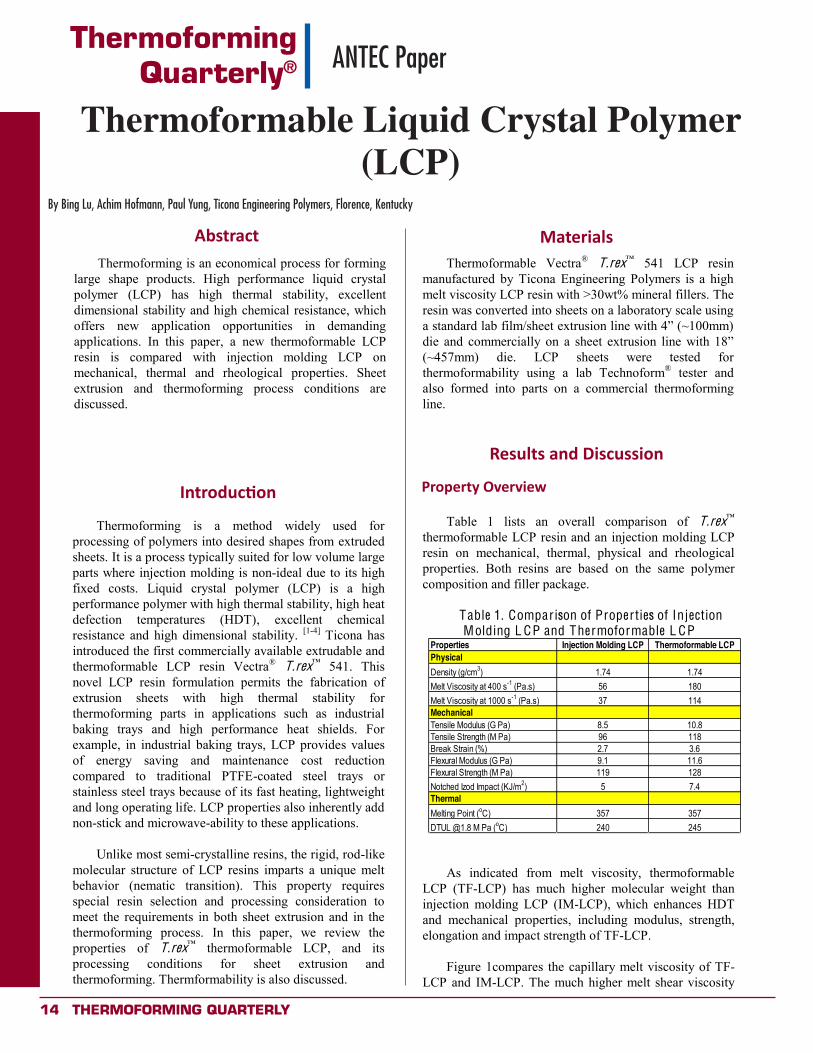
Table 1 lists an overall comparison of T.rex thermoformable LCP resin and an injection molding LCP resin on mechanical, thermal, physical and rheological properties. Both resins are based on the same polymer composition and filler package.
Table 1. Comparison of Properties of Injection Molding L CP and Thermoformable L CP
Properties Injection Molding LCP Thermoformable LCPPhysicalDensity (g/cm3) 1.74 1.74Melt Viscosity at 400 s-1 (Pa.s) 56 180Melt Viscosity at 1000 s-1 (Pa.s) 37 114MechanicalTensile Modulus (G Pa) 8.5 10.8Tensile Strength (M Pa) 96 118Break Strain (%) 2.7 3.6Flexural Modulus (G Pa) 9.1 11.6Flexural Strength (M Pa) 119 128Notched Izod Impact (KJ/m2) 5 7.4ThermalMelting Point (oC) 357 357DTUL @1.8 M Pa (oC) 240 245
As indicated from melt viscosity, thermoformable
LCP (TF-LCP) has much higher molecular weight than injection molding LCP (IM-LCP), which enhances HDT and mechanical properties, including modulus, strength, elongation and impact strength of TF-LCP.
Figure 1compares the capillary melt viscosity of TF-
LCP and IM-LCP. The much higher melt shear viscosity
T H E R M O F O R M A B L E L I Q UID C R YST A L PO L Y M E R (L CP)
Bing Lu, Achim Hofmann, Paul Yung Ticona Engineering Polymers, F lorence, KY
Abstract
Thermoforming is an economical process for forming large shape products. High performance liquid crystal polymer (LCP) has high thermal stability, excellent dimensional stability and high chemical resistance, which offers new application opportunities in demanding applications. In this paper, a new thermoformable LCP resin is compared with injection molding LCP on mechanical, thermal and rheological properties. Sheet extrusion and thermoforming process conditions are discussed.
Introduction
Thermoforming is a method widely used for processing of polymers into desired shapes from extruded sheets. It is a process typically suited for low volume large parts where injection molding is non-ideal due to its high fixed costs. Liquid crystal polymer (LCP) is a high performance polymer with high thermal stability, high heat defection temperatures (HDT), excellent chemical resistance and high dimensional stability. [1-4] Ticona has introduced the first commercially available extrudable and thermoformable LCP resin Vectra® T.rex 541. This novel LCP resin formulation permits the fabrication of extrusion sheets with high thermal stability for thermoforming parts in applications such as industrial baking trays and high performance heat shields. For example, in industrial baking trays, LCP provides values of energy saving and maintenance cost reduction compared to traditional PTFE-coated steel trays or stainless steel trays because of its fast heating, lightweight and long operating life. LCP properties also inherently add non-stick and microwave-ability to these applications.
Unlike most semi-crystalline resins, the rigid, rod-like
molecular structure of LCP resins imparts a unique melt behavior (nematic transition). This property requires special resin selection and processing consideration to meet the requirements in both sheet extrusion and in the thermoforming process. In this paper, we review the properties of T.rex thermoformable LCP, and its processing conditions for sheet extrusion and thermoforming. Thermformability is also discussed.
Materials
Thermoformable Vectra® T.rex 541 LCP resin manufactured by Ticona Engineering Polymers is a high melt viscosity LCP resin with >30wt% mineral fillers. The resin was converted into sheets on a laboratory scale using
die and commercially on (~457mm) die. LCP sheets were tested for thermoformability using a lab Technoform® tester and also formed into parts on a commercial thermoforming line.
Results and Discussion
Property Overview
Table 1 lists an overall comparison of T.rex thermoformable LCP resin and an injection molding LCP resin on mechanical, thermal, physical and rheological properties. Both resins are based on the same polymer composition and filler package.
Table 1. Comparison of Properties of Injection Molding L CP and Thermoformable L CP
Properties Injection Molding LCP Thermoformable LCPPhysicalDensity (g/cm3) 1.74 1.74Melt Viscosity at 400 s-1 (Pa.s) 56 180Melt Viscosity at 1000 s-1 (Pa.s) 37 114MechanicalTensile Modulus (G Pa) 8.5 10.8Tensile Strength (M Pa) 96 118Break Strain (%) 2.7 3.6Flexural Modulus (G Pa) 9.1 11.6Flexural Strength (M Pa) 119 128Notched Izod Impact (KJ/m2) 5 7.4ThermalMelting Point (oC) 357 357DTUL @1.8 M Pa (oC) 240 245
As indicated from melt viscosity, thermoformable
LCP (TF-LCP) has much higher molecular weight than injection molding LCP (IM-LCP), which enhances HDT and mechanical properties, including modulus, strength, elongation and impact strength of TF-LCP.
Figure 1compares the capillary melt viscosity of TF-
LCP and IM-LCP. The much higher melt shear viscosity
Abstract
Introduction
Materials
Results and Discussion
Property Overview
Thermoforming QUArTerLY 15
(continued on next page)
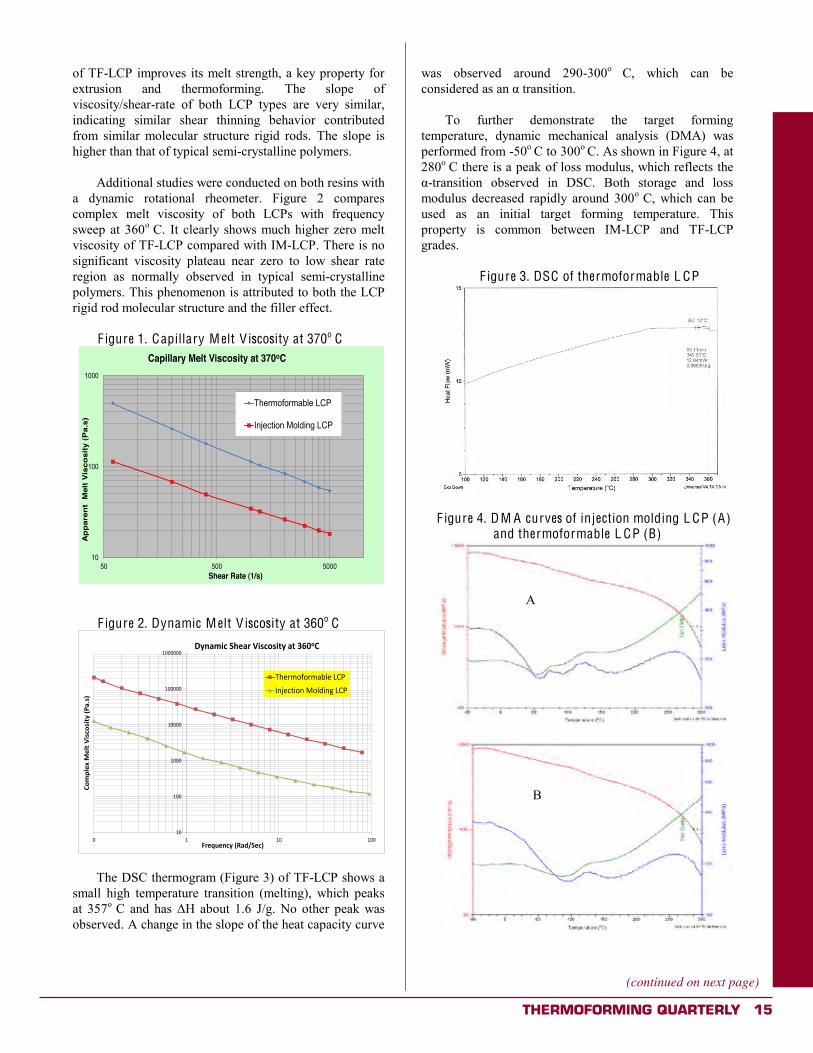
of TF-LCP improves its melt strength, a key property for extrusion and thermoforming. The slope of viscosity/shear-rate of both LCP types are very similar, indicating similar shear thinning behavior contributed from similar molecular structure rigid rods. The slope is higher than that of typical semi-crystalline polymers.
Additional studies were conducted on both resins with
a dynamic rotational rheometer. Figure 2 compares complex melt viscosity of both LCPs with frequency sweep at 360o C. It clearly shows much higher zero melt viscosity of TF-LCP compared with IM-LCP. There is no significant viscosity plateau near zero to low shear rate region as normally observed in typical semi-crystalline polymers. This phenomenon is attributed to both the LCP rigid rod molecular structure and the filler effect.
F igure 1. Capillary M elt V iscosity at 370o C
10
100
1000
50 500 5000
Ap
pare
nt
Mel
t V
isco
sity
(P
a.s)
Shear Rate (1/s)
Capillary Melt Viscosity at 370oC
Thermoformable LCP
Injection Molding LCP
F igure 2. Dynamic M elt V iscosity at 360o C
!"
!""
!"""
!""""
!"""""
!""""""
" ! !" !""
!"#$%&'
()&%*(+
,-."
-,*/(01
23-4
56&78&9./(0:2;<=&.4
>/92#,.(=?&26(+,-."-,*/(2*(@AB"!
#$%&'()(&'*+,%-./0123%456(2-7(,8629-./0
The DSC thermogram (Figure 3) of TF-LCP shows a
small high temperature transition (melting), which peaks at 357o C and has J/g. No other peak was observed. A change in the slope of the heat capacity curve
was observed around 290-300o C, which can be
To further demonstrate the target forming
temperature, dynamic mechanical analysis (DMA) was performed from -50o C to 300o C. As shown in Figure 4, at 280o C there is a peak of loss modulus, which reflects the
-transition observed in DSC. Both storage and loss modulus decreased rapidly around 300o C, which can be used as an initial target forming temperature. This property is common between IM-LCP and TF-LCP grades.
F igure 3. DSC of thermoformable L CP
F igure 4. D M A curves of injection molding L CP (A)
and thermoformable L CP (B)
A
B
16 Thermoforming QUArTerLY
Sheet Extrusion
The quality of extrusion sheets is a key factor for thermoforming process and final part quality. A lab film/sheet extrusion line was first used to make a 50-80 micron film to identify process conditions.
(~100mm)
(~38mm) single screw extruder, L/D=20; coat-hanger die, up to 100mmX100micron opening; no-rip roller, twin stacked 100mm diameterX152mm width polished chrome roller to a varied speed powered take-up roller. The roller temperature was set to 120o C for good surface film quality. The LCP resins were dried at 150o C for 6 hours before extrusion. It is important to note that the drying process is critical. Residual moisture has been observed to lead to polymer degradation and blister formation on the sheet surface.
Table 2 lists the processing conditions and
observations of film extrusion of TF-LCP and IM-LCP. This analysis demonstrated conclusively that TF-LCP produced films with significantly higher quality than IM-LCP. It is believed that the high melt strength is the necessary feature for film/sheet extrusion. From Table 2, the optimal extrusion melt temperature range was determined to be between 345-360o C. (This relatively narrow processing temperature range of LCP compared to traditional semi-crystalline resins is due predominantly to its narrow nematic melt transition behavior.)
Table 2. F ilm extrusion result comparison Roller Speed Melt Temp Die Temp
(inch/sec) (oC) (oC)
1 1.3 330 332Holes in film, difficult to roll,
uneven width
2 1.35 342 340Few holes, still difficult to roll,
unven width
3 0.95 331 335Few holes, still difficult to roll,
unven width
4 0.95 327 330Mlet freezing in the die, few
holes, cracking on edge
1 1.3 347 345Very smooth surface, no flow
mark/gel/holes
2 1.3 347 345
Increased width, very smooth surface, nogel/holes, very few
flow marks
3 1.45 357 355
Increased width, very smooth surface, nogel/holes, very few
flow marks
4 1.45 370 365Surface became rough, edge
starting to crack
5 1.5 375 375Rough surface, edge
cracking
Injection Molding LCP
Thermoformable LCP
Resin Test No. Observation
To translate this technology to a commercial scale, TF-LCP was extruded into sheets on a commercial sheet extrusion line with an (~457mm) die at melt temperature around 355o C and roller temperatures around 120o C. The sheets had the thickness about 0.80-0.90 mm. The sheets had excellent surface quality with no hole/gel/flow mark.
Tensile-bar samples were cut from the sheets, and
tensile properties were measured. Table 3 shows the tensile properties of the sheet in flow and transverse direction.
Table 3. Tensile Properties of T F-L CP Sheets
Property Flow TranseverseModulus (G Pa) 11.2 5.8Tensile Strength (M Pa) 84 42Break Strain (%) 1.3 1.8
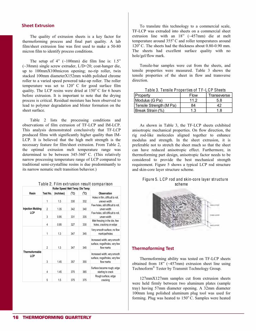
As shown in Table 3, the TF-LCP sheets exhibited anisotropic mechanical properties. On flow direction, the rig rod-like molecules aligned together to enhance modulus and strength. In the sheet extrusion, it is preferable not to stretch the sheet much so that the sheet can have reduced anisotropic effect. Furthermore, in thermoforming part design, anisotropic factor needs to be considered to provide the best mechanical strength requirement. Figure 5 shows a typical LCP rod structure and skin-core layer structure scheme.
F igure 5. L CP rod and skin-core layer structure
scheme
Thermoforming Test
Thermoforming ability was tested on TF-LCP sheets (~457mm) extrusion sheet line using
Technoform® Tester by Transmit Technology Group. 127mmX127mm samples cut from extrusion sheets
were held firmly between two aluminum plates (sample tray) having 57mm diameter opening. A 32mm diameter 100mm long polished aluminum plug tool was used for forming. Plug was heated to 150o C. Samples were heated
Sheet Extrusion
Thermoforming Test
Thermoforming QUArTerLY 17
(continued on next page)
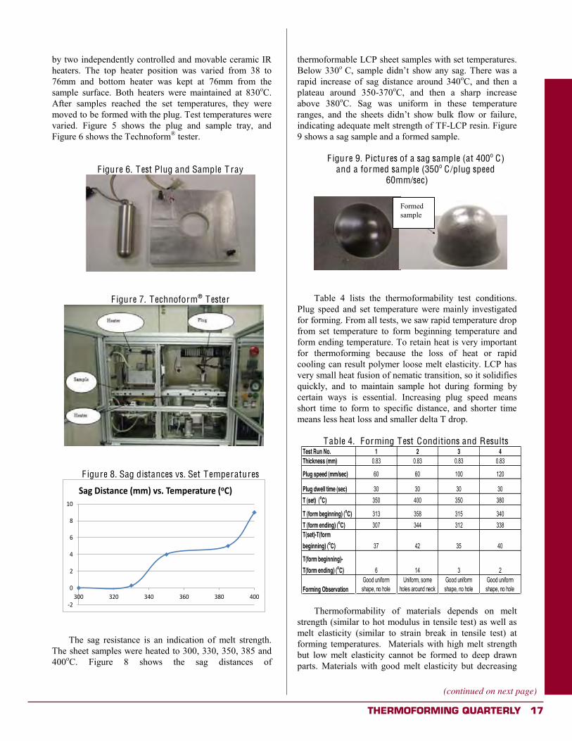
by two independently controlled and movable ceramic IR heaters. The top heater position was varied from 38 to 76mm and bottom heater was kept at 76mm from the sample surface. Both heaters were maintained at 830oC. After samples reached the set temperatures, they were moved to be formed with the plug. Test temperatures were varied. Figure 5 shows the plug and sample tray, and Figure 6 shows the Technoform® tester.
F igure 6. Test Plug and Sample T ray
F igure 7. Technoform® Tester
F igure 8. Sag distances vs. Set Temperatures
:;
"
;
<
=
>
!"
?"" ?;" ?<" ?=" ?>" <""
=2C(>,-*29.&(0##4(D-3(E&#$&62*86&(0"!4
The sag resistance is an indication of melt strength.
The sheet samples were heated to 300, 330, 350, 385 and 400oC. Figure 8 shows the sag distances of
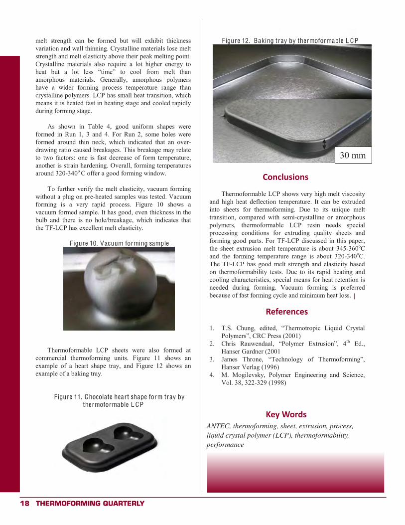
thermoformable LCP sheet samples with set temperatures. Below 330o t show any sag. There was a rapid increase of sag distance around 340oC, and then a plateau around 350-370oC, and then a sharp increase above 380oC. Sag was uniform in these temperature ranges, and the indicating adequate melt strength of TF-LCP resin. Figure 9 shows a sag sample and a formed sample.
F igure 9. Pictures of a sag sample (at 400o C)
and a formed sample (350o C/plug speed 60mm/sec)
Table 4 lists the thermoformability test conditions.
Plug speed and set temperature were mainly investigated for forming. From all tests, we saw rapid temperature drop from set temperature to form beginning temperature and form ending temperature. To retain heat is very important for thermoforming because the loss of heat or rapid cooling can result polymer loose melt elasticity. LCP has very small heat fusion of nematic transition, so it solidifies quickly, and to maintain sample hot during forming by certain ways is essential. Increasing plug speed means short time to form to specific distance, and shorter time means less heat loss and smaller delta T drop.
Table 4. Forming Test Conditions and Results
Test Run No. 1 2 3 4Thickness (mm) 0.83 0.83 0.83 0.83
Plug speed (mm/sec) 60 60 100 120
Plug dwell time (sec) 30 30 30 30T (set) (oC) 350 400 350 380
T (form beginning) (oC) 313 358 315 340T (form ending) (oC) 307 344 312 338T(set)-T(form beginning) (oC) 37 42 35 40
T(form beginning)-T(form ending) (oC) 6 14 3 2
Forming ObservationGood uniform shape, no hole
Uniform, some holes around neck
Good uniform shape, no hole
Good uniform shape, no hole
Thermoformability of materials depends on melt
strength (similar to hot modulus in tensile test) as well as melt elasticity (similar to strain break in tensile test) at forming temperatures. Materials with high melt strength but low melt elasticity cannot be formed to deep drawn parts. Materials with good melt elasticity but decreasing
Formed sample
18 Thermoforming QUArTerLY
melt strength can be formed but will exhibit thickness variation and wall thinning. Crystalline materials lose melt strength and melt elasticity above their peak melting point. Crystalline materials also require a lot higher energy to heat but a amorphous materials. Generally, amorphous polymers have a wider forming process temperature range than crystalline polymers. LCP has small heat transition, which means it is heated fast in heating stage and cooled rapidly during forming stage.
As shown in Table 4, good uniform shapes were
formed in Run 1, 3 and 4. For Run 2, some holes were formed around thin neck, which indicated that an over-drawing ratio caused breakages. This breakage may relate to two factors: one is fast decrease of form temperature, another is strain hardening. Overall, forming temperatures around 320-340o C offer a good forming window.
To further verify the melt elasticity, vacuum forming
without a plug on pre-heated samples was tested. Vacuum forming is a very rapid process. Figure 10 shows a vacuum formed sample. It has good, even thickness in the bulb and there is no hole/breakage, which indicates that the TF-LCP has excellent melt elasticity.
F igure 10. Vacuum forming sample
Thermoformable LCP sheets were also formed at commercial thermoforming units. Figure 11 shows an example of a heart shape tray, and Figure 12 shows an example of a baking tray.
F igure 11. Chocolate heart shape form tray by thermoformable L CP
F igure 12. Baking tray by thermoformable L CP
Conclusions
Thermoformable LCP shows very high melt viscosity and high heat deflection temperature. It can be extruded into sheets for thermoforming. Due to its unique melt transition, compared with semi-crystalline or amorphous polymers, thermoformable LCP resin needs special processing conditions for extruding quality sheets and forming good parts. For TF-LCP discussed in this paper, the sheet extrusion melt temperature is about 345-360oC and the forming temperature range is about 320-340oC. The TF-LCP has good melt strength and elasticity based on thermoformability tests. Due to its rapid heating and cooling characteristics, special means for heat retention is needed during forming. Vacuum forming is preferred because of fast forming cycle and minimum heat loss.
References 1.
01) 2. th Ed.,
Hanser Gardner (2001 3.
Hanser Verlag (1996) 4. M. Mogilevsky, Polymer Engineering and Science,
Vol. 38, 322-329 (1998)
30 mm
Conclusions
References
Key WordsANTEC, thermoforming, sheet, extrusion, process, liquid crystal polymer (LCP), thermoformability, performance
x
Thermoforming QUArTerLY 19
20 Thermoforming QUArTerLY
ThermoformingQuarterly® Industry Practice
SPE Thermoforming Division’s21st Annual Conference Report
By Lesley Kyle, OpenMindWorks, Inc.
The Thermoforming Division hosted its 21st Annual Conference in Grand Rapids,
Michigan, September 23-25. Over 730 industry professionals representing 16 countries attended the Conference to learn about trends and new developments in technology, machinery and materials. The City of Grand Rapids rolled out the red carpet for the Thermoforming Division and Conference attendees who had the opportunity to partake in Art Prize – a huge, citywide indoor and outdoor art exhibition – when they weren’t busy attending sessions or walking the show floor.
Conference attendees had their choice of two full-day workshops, led by McConnell & Company and Mark Strachan. The workshops, attended by nearly 200 industry professionals, addressed fundamental principles and troubleshooting for both roll fed and sheet fed thermoforming. At the conclusion of the Conference, more than 150 attendees participated in the plant tours hosted by Allen Extruders, Formed Solutions, and Fabri-Kal.
Approximately 85 companies exhibited at the Conference with over 10 new exhibiting companies in attendance. Nearly 30 presentations on technical and business-related topics were delivered during two days of conference sessions. Wim DeVos, CEO of the Society of Plastics Engineers, delivered a keynote presentation on plastics in the OEM industries. Todd Shepherd, President of
Shepherd Thermoforming, headlined the second day of sessions with his keynote presentation, “Re-Shoring to North America.”
One of the highlights of the Conference was the Thermoformer of the Year and Parts Competition Awards Dinner. Randy Blin of Blin Management Company was honored as the 2012 Thermoformer of the Year. Mr. Blin, a part of the second father-son winning duo in the history of the award, accepted hearty applause in front of his family, friends, prior winners and several hundred conference attendees.
A variety of awards in different categories were also presented to winners of the Parts Competition. See pagse 28-29 for full details on and photos of the Parts Competition winners. A special presentation highlighting the professional accomplishments of Gwen Mathis, Conference Coordinator, was delivered by Jim Armor of the Thermoforming Division Board of Directors. Ms. Mathis is retiring from her position as Conference Coordinator at the end of this year. Planning is already underway for the SPE 2013 Thermoforming Conference®! Please join us in Atlanta, Georgia, for the 22nd Annual SPE Thermoforming Conference: September 9-12. The conference dates will shift from the weekend to a weekday pattern in 2013. For the most up-to-date information, visit the website at www.thermoformingdivision.com or contact Lesley Kyle at [email protected]. x
Thermoforming QUArTerLY 21
ThermoformingQuarterly® Industry Practice
Thermoforming Continues toCreate Job Opportunities
By Zach Ernest, KLA Industries, Inc.
Thermoforming continues to be a job-creating segment of the plastics industry. In thick-
gauge forming, this can be attributed to increasing applications in the rebounding auto industry and to major manufacturers who are re-shoring their thermoforming operations. In thin-gauge thermoforming, the growth and increased competition in the food and medical packaging markets are driving material and product innovation.
Increased competition and rising material prices continue to constrict margins for plastic thermoformers. As a result, companies are looking for areas that they can control in order to maintain and, where possible, increase profitability. Many organizations have focused their efforts on process improvement with formal training in LEAN manufacturing principles in order to reduce scrap and maximize production rates. One of the primary metrics that thermoformers are targeting for improvement is their Overall Equipment Effectiveness (OEE). To ensure profitability in what can be a high volume, low margin industry, one must minimize downtime for extrusion and thermoforming lines. The implementation and execution of a strong Preventative Maintenance Program is paramount for sustained performance, especially in order to optimize equipment efficiency and increase the life of expensive assets and machinery. This need for an organized maintenance system is creating opportunities for engineers with strong preventative and predictive maintenance and Reliability backgrounds.
Steady M&A activity in the industry has caused some headcount reduction due to synergies created when
companies merge. However, the competition for top talent remains fierce due to demographic changes in the industry and the first wave of retirement for the baby boomer generation. In fact, last year the oldest members of this generation turned 65. Every day for the next 19 years, about 10,000 more will cross that threshold. Companies need to plan for this shift and ensure that they are prepared for the replacement of retiring employees as they will be losing their most experienced people.
To attract top talent, companies must position themselves as innovators who are capable of fostering the career of potential candidates, whether they are hiring new college graduates or trying to lure away engineers or technicians from competitors. Employers are combing resumes for skills including, SPC, Lean, Six Sigma and TPM. Candidates need to make sure that they have both formal training and a wide breadth of skills in order to differentiate themselves. The future is bright for this growing industry and schools like Mid Michigan Community College and Penn College are taking notice by adding thermoforming programs to their curriculum. Whether you are a degreed engineer or a highly skilled maintenance or production worker, one thing is certain: opportunities to advance yourself professionally are all around you. x
Zach Ernest, CPC is VP of Thermoforming for KLA Industries, Inc., an Executive Search Firm specializing in the Polymer and Plastics Industry.
www.klaindustries.com [email protected]

22 Thermoforming QUArTerLY
Meet the Two Fastest in the World.
Peregrine Falcon
202 MPH
MR-J3 Servo2100 Hz Speed FrequencyResponseTime
Multi-Axis for iQ Series
Stand-Alone
Motors up to 6000 RPM
MT Works2 Motion Software
Single-Axis
Maximize your solution with our Servos and Motion Controls.
Blazing fast response time means one thing: maximum throughput. This is paramount to achieving the lowest total of cost ownership (TCO) with your investment. But there’s much more. An auto-tuning function saving hours of set-up and tuning time. A patented design for the most compact and efficient motors in the industry. Bus speeds of 50 Mbps when you combine our servos and motion products. And the widest range of motors available from 50 watt up to 220 kW. All this adds up to why Mitsubishi is ranked #1 in the servo and motion business worldwide. Get with the best to be the best and watch your competitors take a swan dive.
www.meau.com
Thermoforming QUArTerLY 23
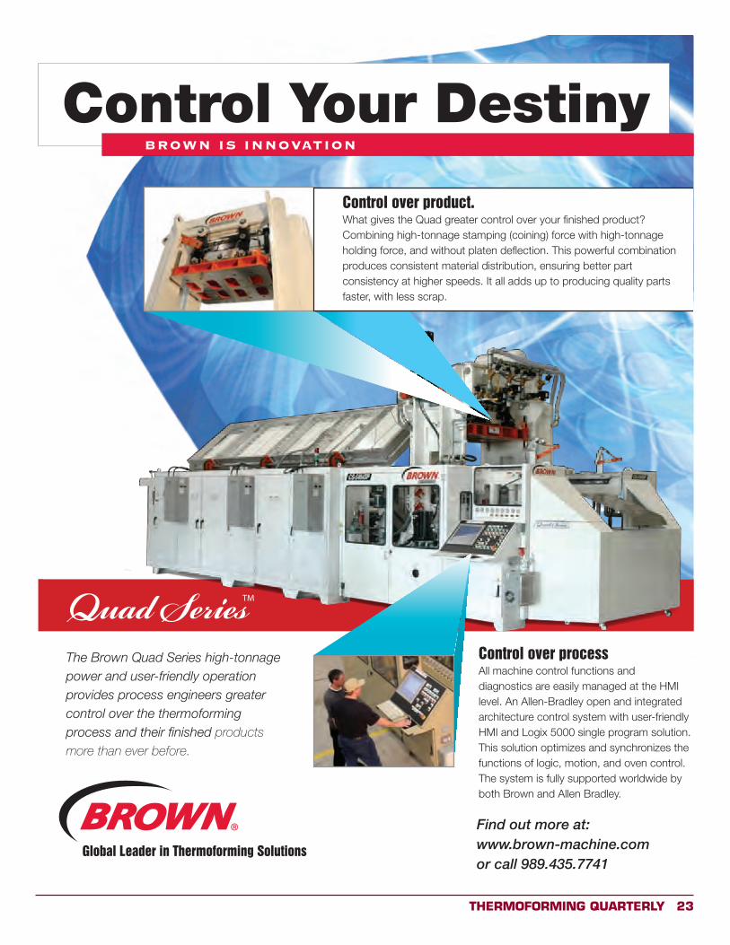
The Brown Quad Series high-tonnage power and user-friendly operation provides process engineers greater control over the thermoforming process and their finished products
more than ever before.
Control over processAll machine control functions and diagnostics are easily managed at the HMI level. An Allen-Bradley open and integrated architecture control system with user-friendly HMI and Logix 5000 single program solution. This solution optimizes and synchronizes the functions of logic, motion, and oven control. The system is fully supported worldwide by both Brown and Allen Bradley.
BROWN IS INNOVATION
Control Your Destiny
Control over product.What gives the Quad greater control over your finished product? Combining high-tonnage stamping (coining) force with high-tonnage holding force, and without platen deflection. This powerful combination produces consistent material distribution, ensuring better part consistency at higher speeds. It all adds up to producing quality parts faster, with less scrap.
Find out more at:www.brown-machine.com or call 989.435.7741
Global Leader in Thermoforming Solutions
24 Thermoforming QUArTerLY
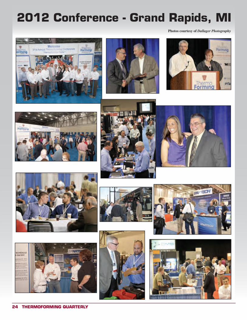
2012 Conference - grand rapids, miPhotos courtesy of Dallager Photography
Thermoforming QUArTerLY 25
Juliet Oehler Goff, President/CEO, Kal Plastics
ISO 9001:2000
From the Editor
If you are an educator, student or advisor in a college or university with a plastics program, we want to hear from you! The SPE
Thermoforming Division has a long and rich tradition of working with academic partners. From scholarships and grants to workforce development programs, the division seeks to promote a stronger bond between industry and academia.
Thermoforming Quarterly is proud to publish news and stories related to the science and business of thermoforming:
• New materials development
• New applications
• Innovative technologies
• Industry partnerships
• New or expanding laboratory facilities
• Endowments
We are also interested in hearing from our members and colleagues around the world. If your school or institution has an international partner, please invite them to submit relevant content. We publish press releases, student essays, photos and technical papers. If you would like to arrange an interview, please contact Brian Winton, Academic Programs, at:
[email protected] or 989.435.7718, ext. 32
REDUCE! REUSE!RECYCLE!
REDUCE! REUSE!RECYCLE!
26 Thermoforming QUArTerLY
UNIVERSITY NEWS
UW Stout Students Visit Wisconsin Manufacturers
By John Shultz, Assistant Professor & Engineering Technology Program Director
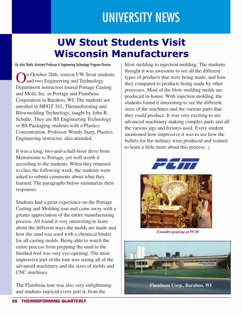
On October 26th, sixteen UW Stout students and two Engineering and Technology
Department instructors toured Portage Casting and Mold, Inc. in Portage and Flambeau Corporation in Baraboo, WI. The students are enrolled in MFGT 342, Thermoforming and Blowmolding Technology, taught by John R. Schultz. They are BS Engineering Technology or BS Packaging students with a Plastics Concentration. Professor Wendy Stary, Plastics Engineering instructor, also attended. It was a long, two-and-a-half-hour drive from Menomonie to Portage, yet well worth it according to the students. When they returned to class the following week, the students were asked to submit comments about what they learned. The paragraphs below summarize their responses. Students had a great experience on the Portage Casting and Molding tour and came away with a greater appreciation of the entire manufacturing process. All found it very interesting to learn about the different ways the molds are made and how the sand was used with a chemical binder for all casting molds. Being able to watch the entire process from prepping the sand to the finished tool was very eye-opening. The most impressive part of the tour was seeing all of the advanced machinery and the sizes of molds and CNC machines.
The Flambeau tour was also very enlightening and students enjoyed every part it, from the
blow molding to injection molding. The students thought it was awesome to see all the different types of products that were being made, and how they compared to products being made by other processes. Most of the blow molding molds are produced in-house. With injection molding, the students found it interesting to see the different sizes of the machines and the various parts that they could produce. It was very exciting to see advanced machinery making complex parts and all the various jigs and fixtures used. Every student mentioned how impressive it was to see how the bullets for the military were produced and wanted to learn a little more about this process. x
Flambeau Corp., Baraboo, WI
Foundry pouring at PCM
Thermoforming QUArTerLY 27
Visit Our Website at: www.
thermoformingdivision.com
Our mission is to facilitate the advancement of thermoforming technologies through education,
application, promotion and research.
Conference CoordinatorLesley Kyle
56 Glenvue Drive
Carmel, NY 10512
914/671-9524
email: [email protected]
SPE NationalExecutive Director
Willem de Vos
13 Church Hill Road
Newtown, CT 06470 USA
Phone: +1 203-775-0471
Fax: +1 203-775-8490
WILLIAM HAROLD “BILL” BENJAMIN William Harold “Bill” Benjamin, 73, of Bellflower, CA, passed away on October 27, 2012 in Bellflower, CA. Bill was born July 19, 1939 in Youngstown, Ohio to Harold and Mary Benjamin. Bill was preceded in death by his parents Harold and Mary Benjamin, and his in-laws, George and Eleanor Grandy.
Bill passed away peacefully at his home surrounded by his wife of 54 years, Beverly “Weiser” Benjamin, and family.
Bill Benjamin was President of Benjamin Mfg. Co., Inc. which he and his wife Beverly started in 1961. His sons, Jeff and Rick, will continue his legacy at Benjamin Mfg. Co., Inc. in Paramount, CA and Lithia Springs, GA. In 1967, he started Benjamin Mfg. Co. in Downey, CA. Bill began thermoforming parts on machinery he designed and built himself since the type of machinery that he envisioned was not available for purchase. Bill continued to design and build several of these machines which are still in use at his plants in California and Georgia. Bill also designed and built a two-station biforcator thermoformer. Bill has six patented products and three trademarks. His first registered trademark was for his “Lustre-Lav” which was made from the forerunner of DR Acrylic ABS material. This material remains a big part of the spa and plumbing industries today. In 1980, a second plant was opened in Lithia Springs, GA. In 2003, Bill was awarded Thermoformer of the Year by the SPE Thermoforming Division where he also served several terms as a member of that group’s Board of Directors.
Bill is survived by three children: Jeff and Toddy Benjamin of Rossmoor, CA; Laurie “Benjamin” and Mike Pike of Palm Desert, CA; Rick and Lisa Benjamin of Bellflower, CA; six grandchildren: Aubrey “Luas” (John) Weston and Amber Luas (Laurie Pike), Whitney “Benjamin” (Chad) Wilkinson, Kayla Benjamin, and Patrick Benjamin (Rick Benjamin), and Farren Benjamin (Jeff Benjamin); brother, Robert Benjamin of Chandler, AZ, sister, Cindy Benjamin of Bellflower, CA, and sister-in-law and her husband, Carol “Grandy” and Robbie Bertocchi, of Douglasville, GA.
In lieu of flowers, the family requests donations be made to: Bill Benjamin Memorial Scholarship Fund, (checks made out to: SPE TF Division, P.O. Box 471, Lindale, GA 30147. x
In Memoriam
28 Thermoforming QUArTerLY
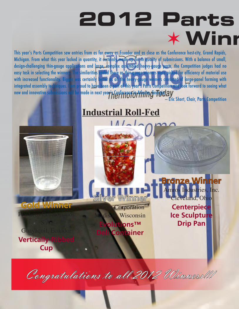
2012 Parts CompetitionV Winners V
Silver WinnerPlacon CorporationMadison, Wisconsin
Evolutions™ Deli Container
Gold WinnerPlasticos Ecuatorianos
S.A.Guayaquil, Ecuador
Vertically-Ribbed Cup
Industrial Roll-Fed
Industrial Roll-Fed Category Gold Winner Plasticos Ecuatorianos S.A. Guayaquil, Ecuador Vertically-Ribbed Cup
Product: Cup, vertically ribbed Capacidad: 6oz. Color: Natural Weight: 1.7g
Product description A product designed for the consumer sector, disposable, less weight and greater strength in their walls
Critical elements of design As has been considered critical elements of design the structured form of the container walls, which act as reinforcement.
Bronze Winner Amros Industries, Inc. Cleveland, Ohio Centerpiece Ice Sculpture Drip Pan
Centerpiece Ice Sculpture Drip Pan was designed for a world known ice sculpting artist who is also a distributor of many unique tools and accessories made specifically for the ice sculpting industry. The main objective of this custom design was to create and build an attractive container which will be able to hold a centerpiece ice sculpture with an average weight of 200 lbs, collect 2 gallons of water from the melting ice and be presentable enough to be the centerpiece of the party table. Our two-piece part design incorporates strategically placed top and bottom reinforcing ribs and is capable of supporting up to 250 lbs of weight.
Centerpiece Ice Sculpture Drip Pan is made out of .040” rigid PVC and runs on the inline thermoformer.
Bronze WinnerAmros Industries, Inc.
Cleveland, Ohio
Centerpiece Ice Sculpture
Drip Pan
Silver Winner Placon Corporation Madison, Wisconsin Evolutions™ Deli Container
Critical Elements of Design • Designed for leak resistance
o Perimeter inside seal is the primary seal and fully engages with a tight fit. o In addition to tight fitting lid, corner snap allows container to stay closed during
impacts and drops (company internal testing/findings). • Designed for tamper-evidence and resistance
o Corner snap developed to securely hold the two flanges together. o Tight lid fit combined with a small lid flange that is turned downward and located
below a small base perimeter rib makes access difficult. o Lid flange is disguised by visually blending with other perimeter “light catching
edges”. • Designed for easy-opening by the customer
o Once separated, the corner flange and lid snap geometry can be grasped for easy opening.
• Designed for strength o Base bottom corners are multi-radius fillets which add structural strength versus
simple chamfers. o Design contains no fragile perforations or slit features found on competing
products. • Designed for clarity
o Slim perimeter profile and lid geometry maximizes product visibility • Designed for less waste and safety
o Product has no “loose” pieces; does not have any breakaway or tear-off portions reducing waste and reducing choking hazard risks posed by competing tamper-evident products.
Congratulations to all 2012 Winners!!!
This year’s Parts Competition saw entries from as far away as Ecuador and as close as the Conference host-city, Grand Rapids, Michigan. From what this year lacked in quantity, it certainly made up for in quality of submissions. With a balance of small, design-challenging thin-gauge applications and large, complex assembled heavy-gauge parts, the Competition judges had no easy task in selecting the winners. The similarities ended there as thin-gauge winners were picked for efficiency of material use with increased functionality. Bigger was certainly better as all the heavy-gauge winners consisted of large-panel forming with integrated assembly techniques. I am proud to have been a part of this year’s Parts Competition and look forward to seeing what new and innovative submissions will be made in next year’s Conference in Atlanta, Georgia.
— Eric Short, Chair, Parts Competition
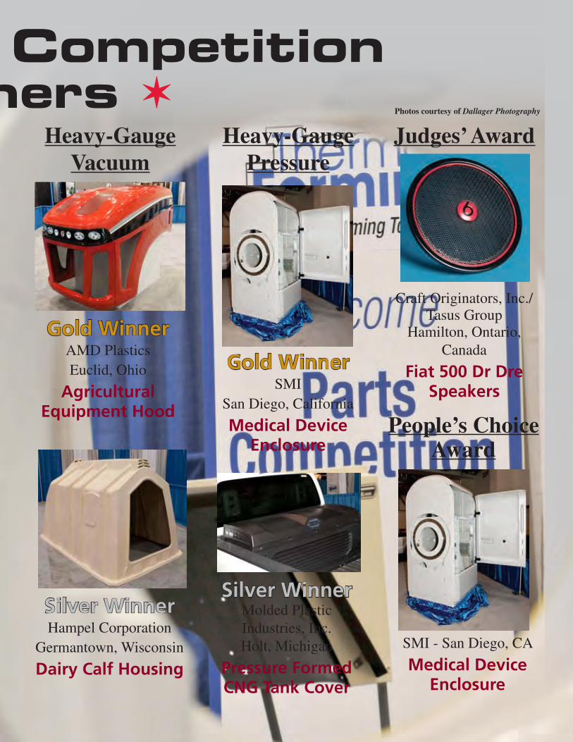
Thermoforming QUArTerLY 29
2012 Parts CompetitionV Winners V
Heavy-Gauge Vacuum
Heavy Gauge - Vacuum Gold Winner AMD Plastics Euclid, Ohio Agricultural Equipment Hood
Intended Use
• OEM, four piece hood assembly for newly designed Apache Sprayer
Critical elements of Design • Large parts – final hood measuring 93.25 inches x 49.5 inches x 56.13 inches • Temperature controlled tooling • Deep and shallow draws. Side panels require large area of sheet and “bag” into a
particularly small draw on the tool
Material Used • Allen ALEXTRA-MV, a coextruded Polycarbonate copolymer capped, PC/ABS
Innovative Aspects • Reduction in previous metal and fiberglass hood weight by 140 lbs. • Utilization of an in-molded color-highly weatherable copolymer, with high heat
resistance and durability allowed transformation from FRP and metal.
Gold WinnerAMD PlasticsEuclid, Ohio
Agricultural Equipment HoodSilver Winner
Hampel Corporation Germantown, Wisconsin Dairy Calf House
Intended Use In 1981 this thermoforming company first introduced a proprietary product line consisting of thermoformed plastic housing used principally for raising calves in the dairy industry. Today, with an installed base of over 400,000 units world-wide, these dairy housing units are responsible for providing an optimal environment for accelerated growth to nearly 2,000,000 calves annually. Innovations Part Size and Depth of Draw The single most innovative aspect of this product is its 67” depth of draw. The part measures 98.5” long x 60.5” wide x 57” tall and is formed from a single sheet of high molecular weight polyethylene (HMWPE). The raw sheet is .375” thick and the finished material thickness ranging from.10” - .200” thick.
Silver WinnerHampel Corporation
Germantown, Wisconsin
Dairy Calf Housing
Heavy-GaugePressure
Gold WinnerSMI
San Diego, California
Medical Device EnclosureSilver Winner
Molded Plastic Industries, Inc. Holt, Michigan Pressure Formed CNG Tank Cover
The critical elements of design were achieving a styled design with molded-in features which would protect the Compressed Natural Gas tank from the daily abuse of the panels in their service life. Alternate designs of fiberglass and metal we considered. However neither material offered the flexibility of design to achieve styling offered utilizing the pressure forming process. The lead design team of Murray Design, LLC ([email protected]) developed the conceptual designs to meet the customer’s initial styling requirement with the modularity for future variant applications – such as tool boxes and larger CNG tanks. Molded Plastic provided the design assistance necessary to achieve the customers styling requirements, panel performance, while maintaining manufacturability and serviceability. Molded Plastic chose CASTEK Aluminum, Incorporated of Elyria, Ohio to build the forming tools as the lead-time for the three (3) tools was less than eight (8) weeks. The tool design team consisted of Tom Petek of CASTEK, Ed Bearse of Advance Plastic Consultants, LLC and Frank Phillips, Jr. of Molded Plastic. Frequent meetings face to face or by WEB EX assured the tools were delivered on time.
Silver WinnerMolded Plastic Industries, Inc.Holt, Michigan
Pressure Formed CNG Tank Cover
Judges’ Award
Craft Originators, Inc./Tasus Group
Hamilton, Ontario, Canada
Fiat 500 Dr Dre Speakers
Photos courtesy of Dallager Photography
People’s Choice Award
SMI - San Diego, CA
Medical Device Enclosure
30 Thermoforming QUArTerLY
Have an Idea for an Article
for TQ?Submission Guidelines
• We are a technical journal. We strive for objective, technical
articles that help advance our readers’ understanding of thermoforming (process, tooling, machinery, ancillary
services); in other words, no commercials.
• Article length: 1,000 - 2,000 words. Look to past
articles for guidance.
• Format: .doc or .docx
Artwork: hi-res images are encouraged (300 dpi) with
appropriate credits.
Send all submissions to Conor Carlin, Editor
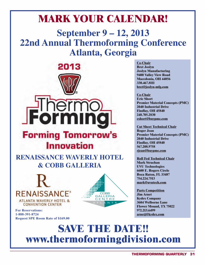
Thermoforming QUArTerLY 31
SAVE THE DATE!!www.thermoformingdivision.com
September 9 – 12, 201322nd Annual Thermoforming Conference
Atlanta, Georgia
MARK YOUR CALENDAR!
RENAISSANCE WAVERLY HOTEL & COBB GALLERIA
For Reservations: 1-888-391-8724Request SPE Room Rate of $169.00
Co-ChairBret JoslynJoslyn Manufacturing9400 Valley View RoadMacedonia, OH [email protected]
Co-ChairEric ShortPremier Material Concepts (PMC)2040 Industrial DriveFindlay, OH [email protected]
Cut Sheet Technical ChairRoger JeanPremier Material Concepts (PMC)2040 Industrial DriveFindlay, OH [email protected]
Roll Fed Technical ChairMark StrachanUVU Technologies6600 E. Rogers CircleBoca Raton, FL [email protected]
Parts CompetitionJim ArnetKydex Company3604 Welborne LaneFlower Mound, TX [email protected]
32 Thermoforming QUArTerLY
Need helpwith your
technical school or college expenses?
If you or someone you know is working towards a career in
the plastic industry, let the SPE Thermoforming Division help support those education goals.
Within this past year alone, our organization has awarded multiple scholarships! Get involved and take advantage of available support from your plastic industry!
Here is a partial list of schools and colleges whose students have benefited from the Thermoforming Division Scholarship Program:
• UMASS Lowell• San Jose State• Pittsburg State• Penn State Erie• University of Wisconsin• Michigan State• Ferris State• Madison Technical College• Clemson University• Illinois State• Penn College
Start by completing the application forms at www.thermoformingdivision.com or at www.4spe.com. x
REDUCE! REUSE! RECYCLE!
Thermoforming QUArTerLY 33
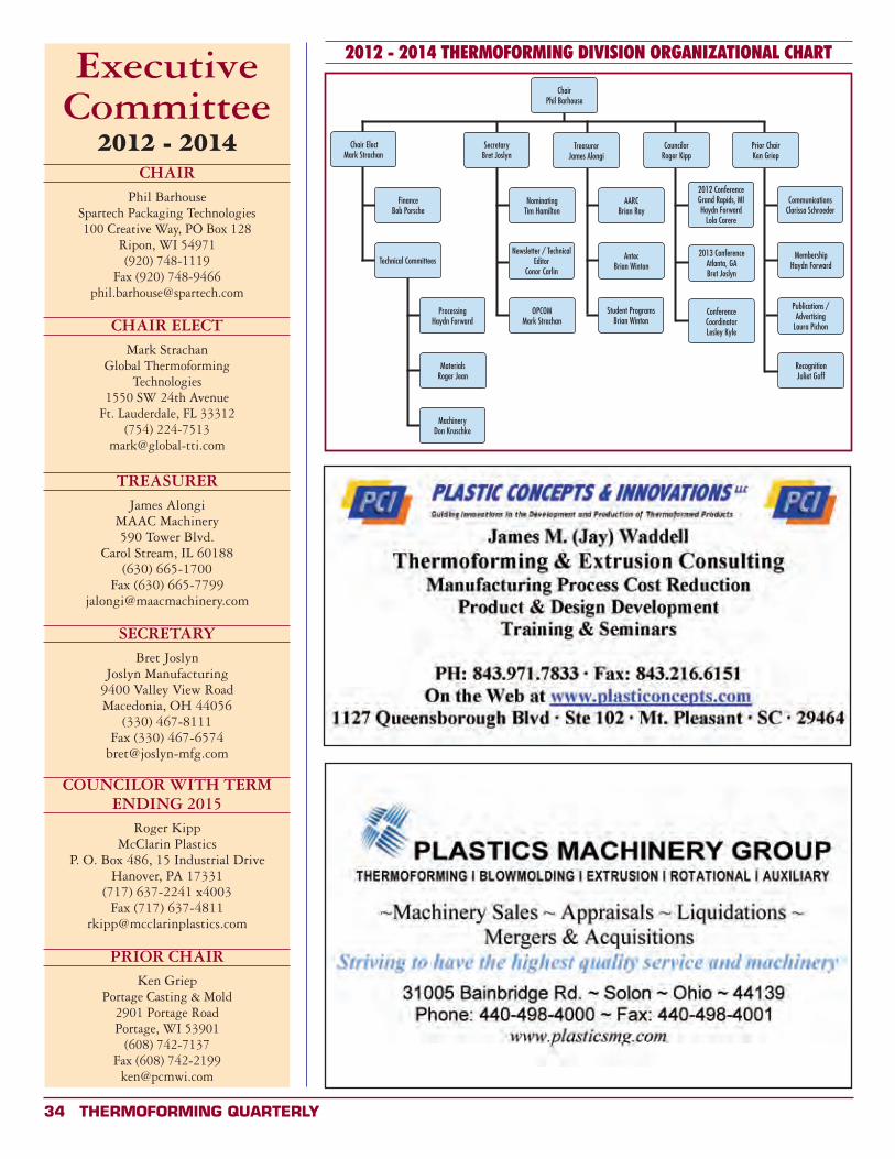
34 Thermoforming QUArTerLY
ExecutiveCommittee
2012 - 2014CHAIR
Phil BarhouseSpartech Packaging Technologies100 Creative Way, PO Box 128
Ripon, WI 54971(920) 748-1119
Fax (920) [email protected]
CHAIR ELECTMark Strachan
Global Thermoforming Technologies
1550 SW 24th AvenueFt. Lauderdale, FL 33312
(754) [email protected]
TREASURERJames Alongi
MAAC Machinery590 Tower Blvd.
Carol Stream, IL 60188(630) 665-1700
Fax (630) [email protected]
SECRETARYBret Joslyn
Joslyn Manufacturing9400 Valley View RoadMacedonia, OH 44056
(330) 467-8111Fax (330) 467-6574
COUNCILOR WITH TERMENDING 2015
Roger KippMcClarin Plastics
P. O. Box 486, 15 Industrial DriveHanover, PA 17331
(717) 637-2241 x4003Fax (717) 637-4811
PRIOR CHAIRKen Griep
Portage Casting & Mold2901 Portage RoadPortage, WI 53901
(608) 742-7137Fax (608) 742-2199
2012 - 2014 THERMOFORMING DIVISION ORGANIZATIONAL CHART
ChairPhil Barhouse
Chair ElectMark Strachan
FinanceBob Porsche
Technical Committees
MaterialsRoger Jean
MachineryDon Kruschke
SecretaryBret Joslyn
Publications / Advertising
Laura Pichon
Newsletter / Technical Editor
Conor Carlin
OPCOMMark Strachan
TreasurerJames Alongi
AARCBrian Ray
Student ProgramsBrian Winton
CouncilorRoger Kipp
Prior ChairKen Griep
2012 ConferenceGrand Rapids, MIHaydn Forward
Lola Carere
AntecBrian Winton
MembershipHaydn Forward
CommunicationsClarissa Schroeder
RecognitionJuliet Goff
2013 ConferenceAtlanta, GABret Joslyn
ConferenceCoordinatorLesley Kyle
ProcessingHaydn Forward
NominatingTim Hamilton
Thermoforming QUArTerLY 35
Board of Directors
MACHINERY COMMITTEE
James AlongiMAAC Machinery590 Tower Blvd.Carol Stream, IL 60188T: 630.665.1700F: [email protected]
Roger FoxThe Foxmor Group1119 Wheaton Oaks CourtWheaton, IL 60187T: 630.653.2200F: [email protected]
Don Kruschke (Chair)Plastics Machinery Group31005 Bainbridge Rd. #6Solon, OH 44739T: 440.498.4000F: [email protected]
Mike SirotnakSolar Products228 Wanaque AvenuePompton Lakes, NJ 07442T: 973.248.9370F: [email protected]
Brian RayRay Products1700 Chablis DriveOntario, CA 91761T: 909.390.9906F: [email protected]
Brian WintonLyle Industries, Inc.4144 W. Lyle RoadBeaverton, MI 48612T: 989-435-7714 x 32F: [email protected]
Bret JoslynJoslyn Manufacturing9400 Valley View RoadMacedonia, OH 44056T: 330.467.8111F: [email protected]
Stephen MurrillProfile Plastics65 S. WaukeganLake Bluff, IL 60044T: 847.604.5100 x29F: [email protected]
Mark StrachanGlobal Thermoforming Technologies1550 SW 24th AvenueFt. Lauderdale, FL 33312T: [email protected]
Jay WaddellPlastics Concepts & Innovations1127 Queensborough RoadSuite 102Mt. Pleasant, SC 29464T: 843.971.7833F: [email protected]
Director EmeritusArt BuckelMcConnell Company3452 Bayonne DriveSan Diego, CA 92109T: [email protected]
Director EmeritusGwen MathisPO Box 471Lindale, GA 30147-0471T: 706.235.9298F: [email protected]
Laura PichonEx-Tech PlasticsPO Box 57611413 Burlington RoadRichmond, IL 60071T: 847.829.8124F: [email protected]
Robert G. PorscheGeneral Plastics2609 West Mill RoadMilwaukee, WI 53209T: 414-351-1000F: [email protected]
Clarissa SchroederAuriga Polymers1551 Dewberry RoadSpartanburg, SC 29307T: 864.579.5047F: [email protected]
Eric ShortPremier Material Concepts11165 Horton RoadHolly, Michigan 48442T: [email protected]
PROCESSING COMMITTEE
Haydn Forward (Chair)Specialty Manufacturing Co.6790 Nancy Ridge RoadSan Diego, CA 92121T: 858.450.1591F: [email protected]
Ken GriepPortage Casting & Mold2901 Portage RoadPortage, WI 53901T: 608.742.7137F: [email protected]
Steve HasselbachCMI Plastics222 Pepsi WayAyden, NC 28416T: 252.746.2171F: [email protected]
Roger KippMcClarin Plastics15 Industrial DrivePO Box 486Hanover, PA 17331T: 717.637.2241F: [email protected]
MATERIALS COMMITTEE
Jim ArmorArmor & Associates16181 Santa Barbara LaneHuntington Beach, CA 92649T: 714.846.7000F: [email protected]
Jim ArnetKydex LLC3604 Welbourne LaneFlower Mount, TX 75022T: [email protected]
Phil BarhouseSpartech Packaging Technologies100 Creative WayPO Box 128 Ripon, WI 54971T: 920.748.1119F: [email protected]
Lola CarereC and K Plastics, Inc.512 Fox Creek CrossingWoodstock, GA 30188T: [email protected]
Juliet GoffKal Plastics2050 East 48th StreetVernon, CA 90058-2022T: [email protected]
Tim HamiltonSpartech Corporation11650 Lakeside Crossing CourtMaryland Heights, MO 63146T: [email protected]
Donald HyltonMcConnell Company646 Holyfield HighwayFairburn, GA 30213T: [email protected]
Roger P. Jean (Chair)Rowmark/PMCPO Box 16052040 Industrial DriveFindlay, OH 45840T: [email protected]
36 Thermoforming QUArTerLY
ThermoformingQuarterly®
FOURTH QUARTER 2012VOLUME 31 n NUMBER 4
Sponsor Index These sponsors enable us to publish Thermoforming Quarterly
n Allen .................................25
n Brown Machine ...................23
n CMT Materials ......................3
n GN Plastics ........................30
n GPEC 2013 ........................33
n Kiefel ................................25
n KMT ....................................7
n Kydex ......... Inside Back Cover
n MAAC Machinery ...................7
n McClarin Plastics .................30
n Mitsubishi Electric ...............22
n Nova Chemicals ....................8
n PCI ...................................34
n Plastics Machinery Group .....34
n PMC ............ Inside Back Cover
n Portage Casting & Mold ........30
n Primex Plastics .....................3
n Productive Plastics ..............25
n Profile Plastics Corp. ...........25
n PTi ..............Inside Front Cover
n Ray Products ......................25
n Solar Products ....................30
n Spartech ...........................32
n Tempco .............................36
n TPS ..................................32
n TSL ...................................19
n Weco Int’l. Inc. ....................3
n Zed Industries ....................25
Thermoforming Division Membership Benefitsn Access to industry knowledge from one central location: www.thermoformingdivision.com.n Subscription to Thermoforming Quarterly, voted “Publication of the Year” by SPE National.n Exposure to new ideas and trends from across the globen New and innovative part design at the Parts Competition.n Open dialogue with the entire industry at the annual conference.n Discounts, discounts, discounts on books, seminars and conferences.n For managers: workshops and presentations tailored specifically to the needs of your operators.n For operators: workshops and presentations that will send you home with new tools to improve your performance, make your job easier and help the
company’s bottom line.Join D25 toDay!
Thermoforming QUArTerLY 37

38 Thermoforming QUArTerLY