Embed Size (px)
Citation preview
Quarterly ®
ThermoformingA JOURNAL OF THE THERMOFORMING DIVISION OF THE SOCIETY OF PLASTICS ENGINEERS FOURTH QUARTER 2013 n VOLUME 32 n NUMBER 4
®
Post Conference Edition
WWW.THERMOFORMINGDIVISION.COM
NSIDE …I2013 Conference Parts Competition Winners pages 10-13
Analytical Modeling of the Thermoformed Process pages 14-21
Lean Manufacturing Makes Formed Plastics More Competitive pages 22-23
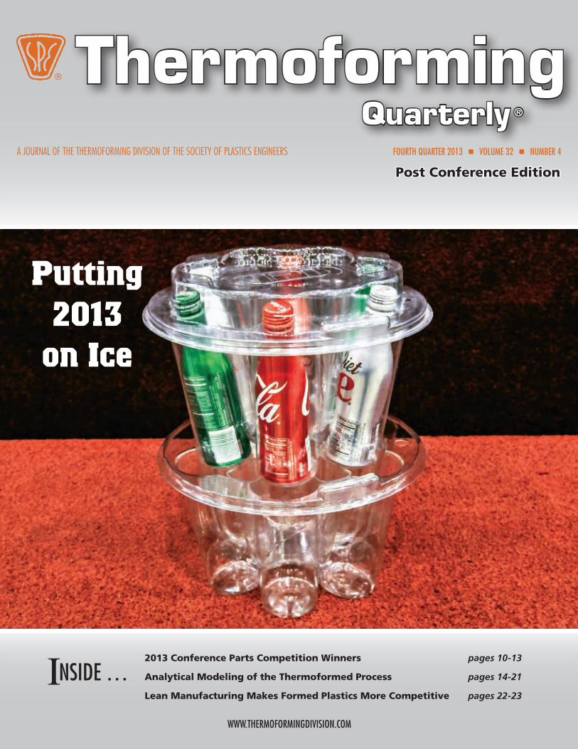
Putting 2013
on Ice
2 Thermoforming QuarTerly
Thermoforming QuarTerly 3
A JOURNAL PUBLISHED EACH CALENDAR QUARTER BY THE THERMOFORMING DIVISION
OF THE SOCIETY OF PLASTICS ENGINEERS
EditorConor Carlin(617) 771-3321
[email protected] Carlin(617) 771-3321
[email protected] Coordinator
Lesley Kyle(914) 671-9524
[email protected] Division
Executive AssistantGwen Mathis(706) 235-9298
Fax (706) [email protected]
Thermoforming Quarterly® is pub-lished four times annually as an infor-mational and educational bulletin to the members of the Society of Plastics Engineers, Thermoforming Division, and the thermoforming industry. The name, “Thermoforming Quarterly®” and its logotype, are registered trademarks of the Thermoforming Division of the Society of Plastics Engineers, Inc. No part of this publication may be reproduced in any form or by any means without prior writ-ten permission of the publisher, copyright holder. Opinions of the authors are their own, and the publishers cannot be held responsible for opinions or representa-tions of any unsolicited material. Printed in the U.S.A.
Thermoforming Quarterly® is registered in the U.S. Patent and Trademark Office (Registration no. 2,229,747). x
ThermoformingQuarterly®
ThermoformingQuarterly®
FOURTH QUARTER 2013VOLUME 32 n NUMBER 4
n DepartmentsChairman’s Corner x 4
Thermoforming in the News x 5
The Business of Thermoforming x 8-9
New Members x 26
Thermoforming and Sustainability x 38-40
n FeaturesAnalytical Modeling of the Thermoforming Process x 14-21
Lean Manufacturing Makes Formed Plastics More Competitive x 22-23
Cause and Effect of Mold Characteristics, Part 2 x 24-25
Heating and Cooling the Sheet x 28-30
Infrared Temperature Measurement: Optimizing Stationary and Rotary Thermoforming x 32-36
n In This Issue2013 Thermoforming Conference Parts Competition Winners x 10-13
Report From Dusseldorf K 2013 x 41-47
Eyetracking Study Report: Clamshells vs Paperboard Boxes x 48-52
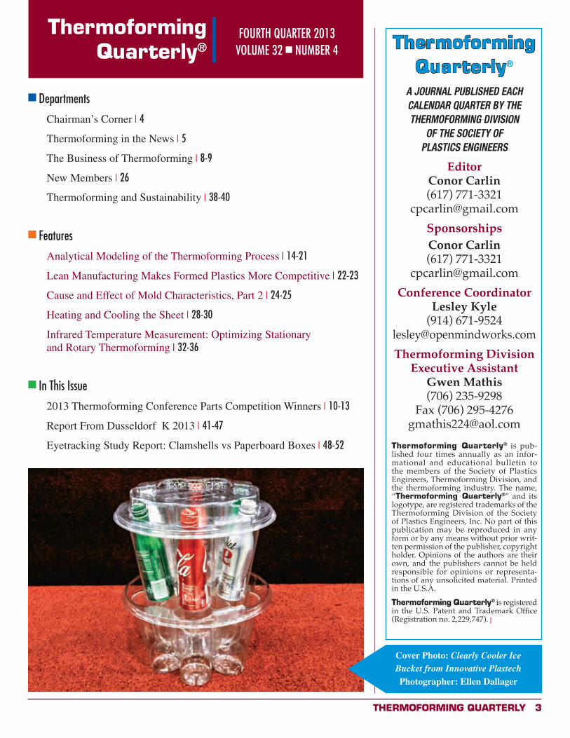
Cover Photo: Clearly Cooler Ice Bucket from Innovative PlastechPhotographer: Ellen Dallager
4 Thermoforming QuarTerly
ThermoformingQuarterly® Chairman’s Corner
Mar
k St
rach
an
Poised for SuccessWow! It’s almost the end of 2013 and
what a tremendous year it has been for
the thermoforming industry. I have seen a
definite increase in thin gage business due
to re-shoring of products previously lost
to China. Thermoforming equipment and
tooling manufacturers have also risen to the
occasion with cutting-edge technologies
that greatly enhance our capabilities and
efficiencies. I base this on first-hand
knowledge from the recent K-Show in
Dusseldorf, Germany.
This edition of the Quarterly is now the
second edition available in digital format.
Available to our international members,
the electronic version allows all advertisers
and sponsors to include hyperlinks to
their websites. On behalf of the board,
I’d like to extend a big “thank you” to all
those that took the time to submit articles
for the last (largest ever!) issue. We are
planning to maintain this high level of
material, with both quality and quantity
for your education and reading pleasure.
We continue to encourage all members to
submit white papers and articles related to
the thermoforming industry. The magazine
is one of the more visible ways that the
division strengthens ties between industry
and academia, between thermoformers
and suppliers, and between students and
professionals. The vitality of our industry
depends on our collective efforts.
The SPE Thermoforming Division Board
of Directors are all very enthusiastic
volunteers who dedicate their valuable time
to promote the industry and would love
to interact with you during the technical
sessions at board meetings. As I and
previous chairs have stated, we welcome
members to join us at any of our three
board meetings. Please contact Lesley Kyle
at [email protected] if you are
interested in joining us at our next meeting
in Huntington Beach, CA in February.
Thank you to the committees and
volunteers who helped make the Atlanta
conference a great success.
Best wishes for the holidays. x
If you or someone you know
is working towards a career in
the plastic industry, let the SPE
Thermoforming Division help
support those education goals.
Here is a partial list of schools
and colleges whose students
have benefited from the
Thermoforming Division
Scholarship Program:
• UMASS Lowell
• San Jose State
• Pittsburg State
• Penn State Erie
• University of Wisconsin
• Michigan State
• Ferris State
• Madison Technical College
• Clemson University
• Illinois State
• Penn College
Start by completing
the application forms at
www.thermoformingdivision.com
or at www.4spe.com
Need help with your technical school or college expenses?
Thermoforming QuarTerly 5
Thermoformer East Jordan Plastics Investing in Michigan PlantBy Jeremy Carroll, Staff Reporter, Plastic News
SEPTEMBER 25, 2013 — East Jordan Plastics Inc. is seeking a 12-year tax break on new equipment in two facilities in South Haven, Mich. The company, located in nearby East Jordan, is a horticultural thermoformer and plastics recycler. The tax break is on equipment and machinery at two locations totaling $1.8 million. The actual abatement on taxes would be $93,825 over the course of a 12-year period, according to city documents.
The improvements would allow for better storage and shipping at one location to serve as a logistics center and an increase in production and shipping at another location.
The company has approximately 250 employees, all located in Michigan. The company said it will create four new jobs and retain five jobs as a direct result of the equipment and improvements.
Bertram Capital Announces Acquisition of RowmarkTransaction Represents Firm's Third Investment in Plastics Industry
By Bertram Capital
OCTOBER 2, 2013, SAN MATEO, CALIF. — Rowmark LLC ("Rowmark"), a leading manufacturer of highly engineered extruded plastic sheet used for engraving and specialty applications, announced today its partnership with Bertram Capital. Based in Findlay, OH, Rowmark represents Bertram Capital's third platform investment in the plastics industry. In addition to the equity investment in Rowmark, Bertram Capital also provided subordinated debt to finance the acquisition.
"Rowmark is an established market leader with strong brand recognition, supported by state-of-the-art manufacturing and an unmatched distribution network," said Kevin Yamashita, Partner at Bertram Capital. "Rowmark is led by a capable and experienced management team. They have built a platform with robust operating fundamentals and long standing customer relationships across a variety of industries. We look forward to further expanding Rowmark's footprint and accelerating the company's growth in partnership with management."
Rowmark delivers solutions through two complementary product divisions: Engraving Products and Premier Material Concepts ("PMC"). The Engraving Products division has the most recognized global brand of engravable sheet worldwide, which is sold exclusively through an international network of authorized distributors in more than 80 countries. PMC is a leading provider
Thermoforming in the news
of highly engineered custom extruded sheet and roll stock for specialty thermoforming applications across a diverse set of end markets.
"Rowmark represents exactly the type of business Bertram Capital seeks to partner with, offering a compelling value proposition, world-class management team, and differentiated engineering and manufacturing capabilities," noted Jeff Drazan, Managing Partner of Bertram Capital. "By applying our Bertram High 5SM business building methodology, we believe Rowmark is uniquely positioned for significant growth opportunities, through both organic initiatives and add-on acquisitions."
Bertram Capital was introduced to Rowmark by Piper Jaffray (formerly Edgeview Partners), a leading international investment banking firm. "We are grateful to John Tye, Managing Director in Piper Jaffray's Diversified Industrials & Services group, for his leadership in managing the Rowmark sale process," said Kevin Yamashita. "Rowmark met the rigorous criteria we apply to our investments and represents the type of industry leading company we seek to invest in at Bertram Capital. John and his team ran a thorough, fair and comprehensive sale process."
Thermoformer Inline Plastics Plans ExpansionBy Michael Lauzon, Correspondent for Plastics News
OCTOBER 11, 2013 — Packaging thermoformer Inline Plastics Corp. continues its expansion thrust with the addition of machinery and floor space. Inline has added 150,000 square feet to its Shelton, Conn., head office plant and started up a new thermoforming line there this past summer. The extra space is being used for manufacturing, warehousing and offices.
In Salt Lake City, Utah, Inline is starting up a new line this month. At its McDonough, Ga., plant it will install a new thermoforming line in January. It has added 42,000 square feet of manufacturing and warehouse space to this facility. The recently announced expansions follow by about a year other capacity additions in Salt Lake City and McDonough announced by Inline.
“We are investing more than $6 million in machinery and tooling this year to ensure that we can meet the needs of our valued customers,” stated Inline President Tom Orkisz.
Inline expects to create 60 new jobs with the capacity growth.It specializes in clam shells and other thermoformed packaging such as its Safe-T-Fresh line of tamper-evident containers. The firm’s PET packaging is sold for fresh-cut produce, salads, food service, baked goods and deli offerings.
Inline said the new thermoformers are large-platform, roll-fed machines but it did not disclose the suppliers. Inline said
6 Thermoforming QuarTerly
customers will benefit from the expansion through consistent lead times, increased flexibility and local production of its most popular packaging.
Inline, founded in 1968, opened its Salt Lake City operation in 2004 and five years later started up In McDonough. In addition to PET packaging, it offers wash-down automated equipment to load, close and label its containers.
Deal Combines California ThermoformersBy Jeremy Carroll, Staff Reporter, Plastic News
NOVEMBER 13, 2013 — Advanced Thermoforming Enterprise (ATE) and InterTrade Industries Ltd. will combine operations as ATE-InterTrade following an acquisition. Innotek, announced the purchase of Oceanside, Calif.-based ATE on Nov. 13. Terms of the deal were not disclosed.
InterTrade Industries is a heavy- and thin-gauge plastic thermoformer while ATE specializes in developing medical plastic packaging, engineering and supplying thermoformed
plastic packaging to medical and pharmaceutical companies. ATE will continue to operate in California and all its employees will remain in place, American Innotek announced. The move will help the Escondido, Calif.-based American Innotek move into the medical plastics market and further diversify the company, said the company’s Chairman and CEO Cass Cassidy.
“I founded this company in 1988 with the goal of combining technology with manufacturing efficiencies to fulfill unique marketplace needs,” he said in a statement. “This acquisition represents that spirit and continues to diversify our offerings, thus poising us for future growth.”
Combined, ATE-InterTrade will employ more than 50 people and have more than 70,000 square feet of operations. InterTrade Industries had an estimated $8 million in sales and 16 machines, according to Plastics News’ ranking of North American thermoformers. x
Information is power. It also means profit.
Introducing ToolVu. Cut Scrap. Reduce Downtime. Faster Startup.
ToolVu is a powerful piece of equipment that connects
directly to your thermoformer to monitor every step
of the process and provide a real-time, detailed view
of the entire production run. Never before has this
much precise information been available to operators.
And this information translates to profit. You’ll lower
your startup times and startup scrap by as much as
50%. You’ll boost efficiency and avoid thousands of
wasted units as well as reduce the risk of damaged
equipment and costly shutdowns. ToolVu will even proactively detect
problems, provide analytics, troubleshoot and warn the operator in
real-time. Plus, every action is recorded so you can go back and audit
past runs. Put this powerful technology to work for you today.
Thermoforming just got smarter
Leasing options are now available.Find out how easy it is to start working smarter.www.ToolVu.com | 561-674-9415 | [email protected]
ToolVu provides real-time quality control monitoring of:� Tool Temperatures
� Clamp/Coiner/Downholder Air Pressure
� Clamp/Coiner/Downholder Position
� Form Air Pressure
� Vacuum – Dual Pos/Neg Pressure
� Plug Speed, Distance & Force
� Tool Strain
� Machinery & Tooling Health
� Sheet Temperatures
� Ambient Air Temperature
Thermoforming Quarterly half page ad_Layout 1 11/15/13 2:02 PM Page 1

Thermoforming QuarTerly 7
Become a
Thermoforming
Quarterly
Sponsor
in 2014!
Sponsorship opportunities include
4-color, full page, and 1/2 page ad spaces.
RESERVE YOUR PRIME
SPONSORSHIP
SPACE TODAY.
Questions? Call or emailConor Carlin
Editor617-771-3321
Planning is underway for the 2014 SPE
Thermoforming Conference!
The 23rd Annual Thermoforming
Conference will beSeptember 15-18
at theRenaissance Schaumburg
Convention Center in Schaumburg, Illinois
Visit
thermoformingdivision.com
for updates.
8 Thermoforming QuarTerly
ThermoformingQuarterly® The Business of Thermoforming
Inside the Numbers: Insights from the North American Plastics Industry StudyBy Jeff Mengel
Editor's Note: We are grateful to Plante & Moran for providing us with a unique executive summary of the NAPPI study. Readers can contact the company directly for more details and pricing on the full study. www.plantemoran.com
In October 2013, Plante Moran released its annual benchmarking report for the North American plastics industry. This in-depth benchmarking survey collects data in a range of areas – financial performance, operational performance, human resources, sales and marketing, and corporate strategy and value proposition – from North American plastics processors. Through October, we’ve received data from 84 companies representing 131 facilities across the United States, Canada and Mexico.
Here’s a look inside some of the noteworthy findings from our 2013 study, which primarily covers survey participant data for the period of 2011-12.
Healthy Growth in Utilization, Productivity and Profit MarginsMost of the survey participants enjoyed a healthy growth of over 15 percent in earnings before interest, taxes, and depreciation and amortization (EBITDA) from the prior years. Though not every company experienced an increase – roughly 25 percent of the population lost ground – a number of factors contributed to strong earnings for most companies.
• Press utilization increased for the third straight year. The top quartile of our survey population surpassed 50 percent utilization for all presses based on a 24/7 basis. While press utilization does not correlate with profitability as weak companies routinely low-ball quotes to keep the presses running, the reduction of available capacity has brought pricing discipline to the industry. With a modest reduction in average complexity levels, it appears more companies have grown strategically, meaning some low-volume customers have been priced out of company’s customer bases.
• Not all process segments have enjoyed the successes of the industry as a whole. Industrial thermoforming continues to shrink as the tooling costs and capability
of the injection molding process expands, resulting in compressed earnings. On the other hand, thermoformers serving the packaging industry enjoyed substantial productivity and earnings
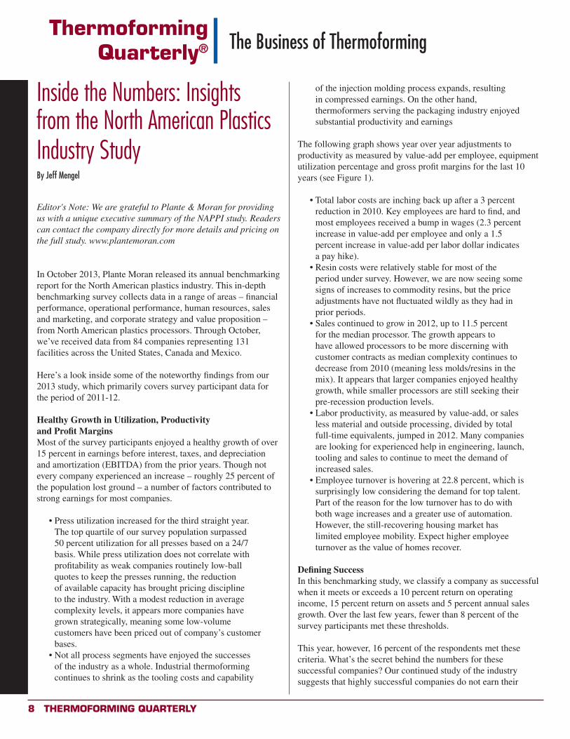
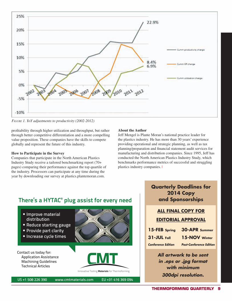
The following graph shows year over year adjustments to productivity as measured by value-add per employee, equipment utilization percentage and gross profit margins for the last 10 years (see Figure 1).
• Total labor costs are inching back up after a 3 percent reduction in 2010. Key employees are hard to find, and most employees received a bump in wages (2.3 percent increase in value-add per employee and only a 1.5 percent increase in value-add per labor dollar indicates a pay hike).
• Resin costs were relatively stable for most of the period under survey. However, we are now seeing some signs of increases to commodity resins, but the price adjustments have not fluctuated wildly as they had in prior periods.
• Sales continued to grow in 2012, up to 11.5 percent for the median processor. The growth appears to have allowed processors to be more discerning with customer contracts as median complexity continues to decrease from 2010 (meaning less molds/resins in the mix). It appears that larger companies enjoyed healthy growth, while smaller processors are still seeking their pre-recession production levels.
• Labor productivity, as measured by value-add, or sales less material and outside processing, divided by total full-time equivalents, jumped in 2012. Many companies are looking for experienced help in engineering, launch, tooling and sales to continue to meet the demand of increased sales.
• Employee turnover is hovering at 22.8 percent, which is surprisingly low considering the demand for top talent. Part of the reason for the low turnover has to do with both wage increases and a greater use of automation. However, the still-recovering housing market has limited employee mobility. Expect higher employee turnover as the value of homes recover.
Defining SuccessIn this benchmarking study, we classify a company as successful when it meets or exceeds a 10 percent return on operating income, 15 percent return on assets and 5 percent annual sales growth. Over the last few years, fewer than 8 percent of the survey participants met these thresholds.
This year, however, 16 percent of the respondents met these criteria. What’s the secret behind the numbers for these successful companies? Our continued study of the industry suggests that highly successful companies do not earn their
Thermoforming QuarTerly 9
Figure 1. YoY adjustments to productivity (2002-2012)
profitability through higher utilization and throughput, but rather through better competitive differentiation and a more compelling value proposition. These companies have the skills to compete globally and represent the future of this industry.
How to Participate in the SurveyCompanies that participate in the North American Plastics Industry Study receive a tailored benchmarking report (70+ pages) comparing their performance against the top quartile of the industry. Processors can participate at any time during the year by downloading our survey at plastics.plantemoran.com.
US +1 508 226 390 www.cmtmaterials.com EU +31 416 369 094
CMT Thermoforming Qtrly 3.25x4.75.pdf 1 9/25/13 10:17 PMQuarterly Deadlines for
2014 Copy and Sponsorships
ALL FINAL COPY FOR
EDITORIAL APPROVAL
15-FEB Spring 30-APR Summer
31-JUL Fall 15-NOV Winter
Conference Edition Post-Conference Edition
All artwork to be sent in .eps or .jpg format
with minimum
300dpi resolution.
About the AuthorJeff Mengel is Plante Moran’s national practice leader for the plastics industry. He has more than 30 years’ experience providing operational and strategic planning, as well as tax planning/preparation and financial statement audit services for manufacturing and distribution companies. Since 1995, Jeff has conducted the North American Plastics Industry Study, which benchmarks performance metrics of successful and struggling plastics industry companies. x
10 Thermoforming QuarTerly
2013 THERMOFORMING CONFERENCE AND PARTS COMPETITIONBy Bill Bregar, Plastic News
A see-through beverage cooler that fully displays cans and bottles netted two awards for Innovative Plastech Inc. of Batavia, Ill., at the SPE Thermoforming Division's annual parts competition. The Clearly Cooler ice bucket won first place in the roll-fed food packaging category and picked up the Judges Award at the SPE Thermoforming Conference in Atlanta. Innovative Plastech molds the cooler from recycled PET. It holds a six-pack of 12-ounce bottles and stores ice in the middle section. The bottles stay secure even when the cooler is turned upside down.
Also at the conference, Hampel Corp. of Germantown, Wis., won two awards for two separate heavy-gauge products. The People's Choice Award went to Say Plastics Inc. of McSherrytown, Pa., for a thermoformed rear emergency- exit door for a medium-duty transit bus that replaced a steel door.
Jim Arnet, parts competition chairman, announced the winners Sept. 10 during the conference, which ran Sept. 9-12.
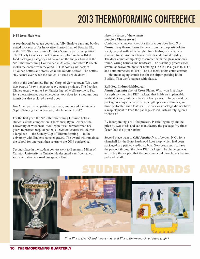
For the first year, the SPE Thermoforming Division held a student awards competition. The winner, Ryan Enzler of the University of Wisconsin-Stout, won for a thermoformed heal guard to protect hospital patients. Division leaders will deliver a large cup — the Stanley Cup of Thermoforming — to the university with Enzler's name engraved. The award will remain at the school for one year, then return to the 2014 conference.
Second-place in the student contest went to Benjamin Miller of Carleton University in Ontario. He designed a self-contained, safe alternative to a road emergency flare.
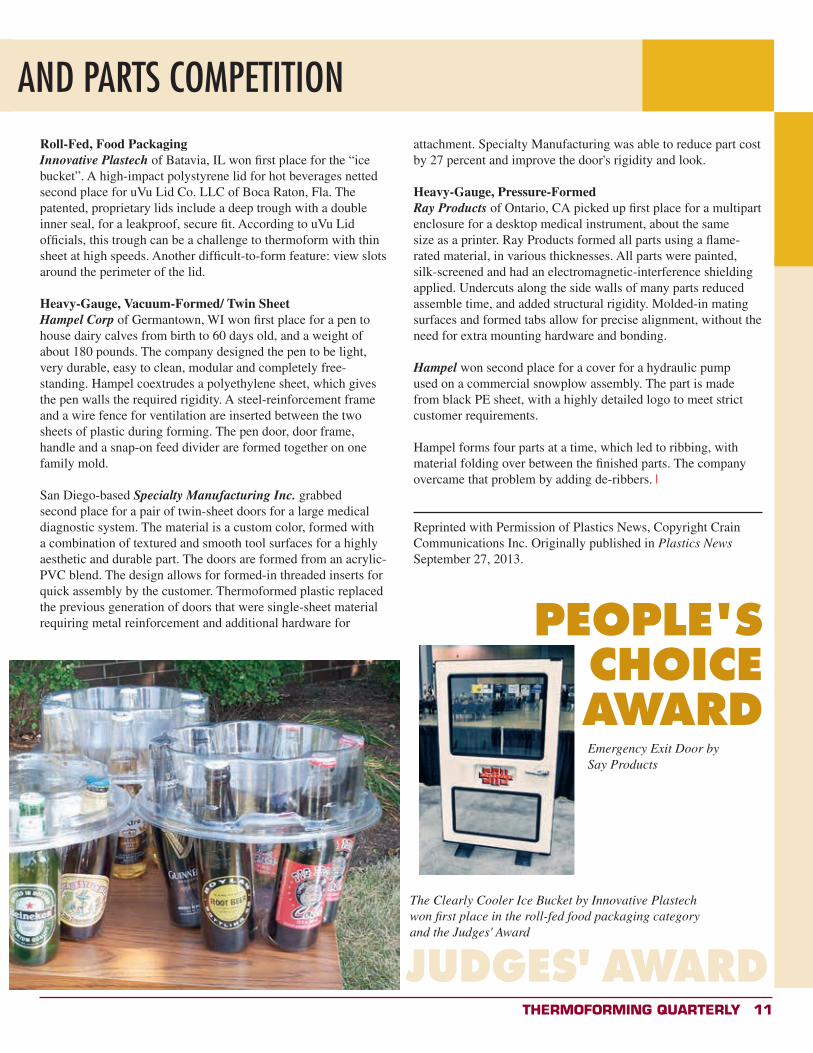
Here is a recap of the winners:People's Choice AwardConference attendees voted for the rear bus door from Say Plastics. Say thermoforms the door from thermoplastic olefin sheet, capped with white acrylic, for a high-gloss, weather-resistant finish. An inner frame provides additional rigidity. The door comes completely assembled with the glass windows, frame, wiring harness and hardware. The assembly process uses several adhesive methods for bonding TPO to TPO, glass to TPO and aluminum/steel to TPO. The old metal doors could corrode — picture an aging shuttle bus for the airport parking lot in Buffalo. That won't happen with plastic.
Roll-Fed, Industrial/MedicalPlastic Ingenuity Inc. of Cross Plains, Wis., won first place for a glycol-modified PET package that holds an implantable medical device, with a catheter delivery system. Judges said the package is unique because of its length, perforated hinges, and three perforated snap features. The previous package did not have a snap element to keep the package closed, instead relying on a friction fit.
By incorporating a roll-fed process, Plastic Ingenuity cut the price by two-thirds and can manufacture the package five times faster than the prior version.
Second place went to CMI Plastics Inc. of Ayden, N.C., for a clamshell for the Bona hardwood floor mop, which had been packaged in a printed cardboard box. Now consumers can see the product through the clear PET package. The challenge was to display the mop so that the consumer could touch the cleaning pad and handle.
STUDENT AWARDS
First Place: Heal Guard (above); Second Place: Emergency Road Flare (right)
Thermoforming QuarTerly 11
2013 THERMOFORMING CONFERENCE AND PARTS COMPETITIONRoll-Fed, Food PackagingInnovative Plastech of Batavia, IL won first place for the “ice bucket”. A high-impact polystyrene lid for hot beverages netted second place for uVu Lid Co. LLC of Boca Raton, Fla. The patented, proprietary lids include a deep trough with a double inner seal, for a leakproof, secure fit. According to uVu Lid officials, this trough can be a challenge to thermoform with thin sheet at high speeds. Another difficult-to-form feature: view slots around the perimeter of the lid.
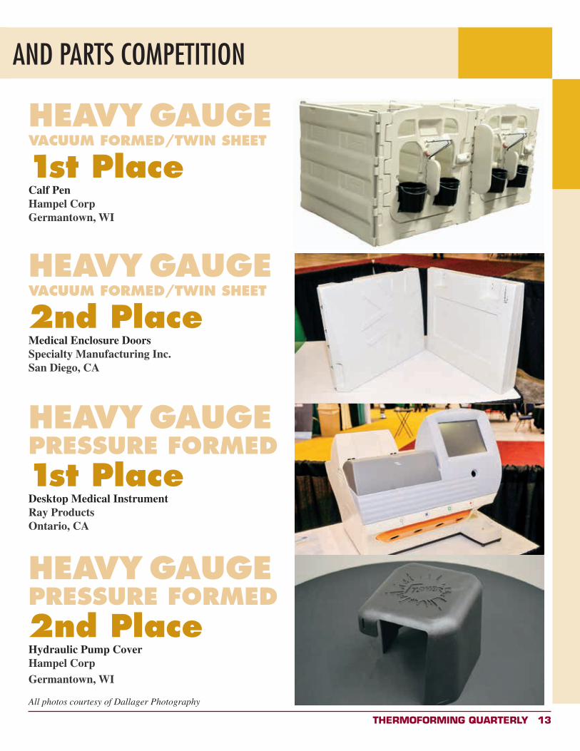
Heavy-Gauge, Vacuum-Formed/ Twin SheetHampel Corp of Germantown, WI won first place for a pen to house dairy calves from birth to 60 days old, and a weight of about 180 pounds. The company designed the pen to be light, very durable, easy to clean, modular and completely free-standing. Hampel coextrudes a polyethylene sheet, which gives the pen walls the required rigidity. A steel-reinforcement frame and a wire fence for ventilation are inserted between the two sheets of plastic during forming. The pen door, door frame, handle and a snap-on feed divider are formed together on one family mold.
San Diego-based Specialty Manufacturing Inc. grabbed second place for a pair of twin-sheet doors for a large medical diagnostic system. The material is a custom color, formed with a combination of textured and smooth tool surfaces for a highly aesthetic and durable part. The doors are formed from an acrylic-PVC blend. The design allows for formed-in threaded inserts for quick assembly by the customer. Thermoformed plastic replaced the previous generation of doors that were single-sheet material requiring metal reinforcement and additional hardware for
attachment. Specialty Manufacturing was able to reduce part cost by 27 percent and improve the door's rigidity and look.
Heavy-Gauge, Pressure-FormedRay Products of Ontario, CA picked up first place for a multipart enclosure for a desktop medical instrument, about the same size as a printer. Ray Products formed all parts using a flame-rated material, in various thicknesses. All parts were painted, silk-screened and had an electromagnetic-interference shielding applied. Undercuts along the side walls of many parts reduced assemble time, and added structural rigidity. Molded-in mating surfaces and formed tabs allow for precise alignment, without the need for extra mounting hardware and bonding.
Hampel won second place for a cover for a hydraulic pump used on a commercial snowplow assembly. The part is made from black PE sheet, with a highly detailed logo to meet strict customer requirements.
Hampel forms four parts at a time, which led to ribbing, with material folding over between the finished parts. The company overcame that problem by adding de-ribbers. x
Reprinted with Permission of Plastics News, Copyright Crain Communications Inc. Originally published in Plastics News September 27, 2013.
PEOPLE'S CHOICE AWARDEmergency Exit Door by Say Products
JUDGES' AWARD
The Clearly Cooler Ice Bucket by Innovative Plastech won first place in the roll-fed food packaging category and the Judges' Award
12 Thermoforming QuarTerly
2013 THERMOFORMING CONFERENCE AND PARTS COMPETITION
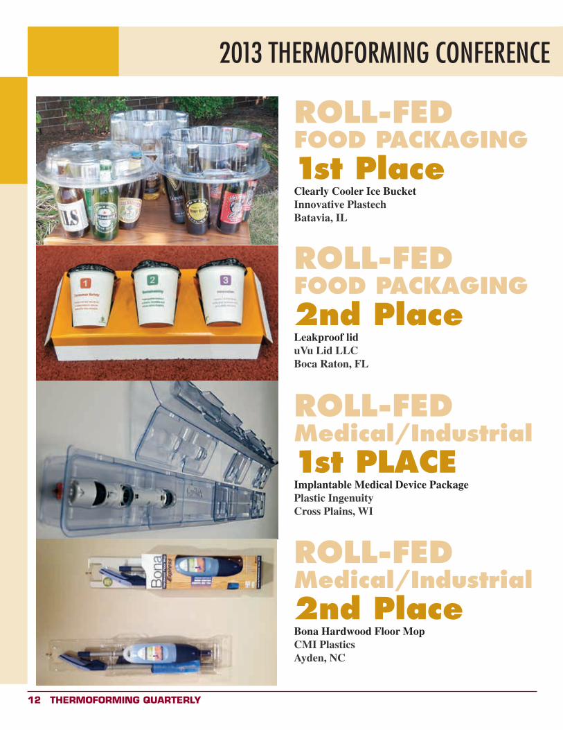
ROLL-FEDFOOD PACKAGING1st PlaceClearly Cooler Ice BucketInnovative PlastechBatavia, IL
ROLL-FEDFOOD PACKAGING2nd PlaceLeakproof liduVu Lid LLCBoca Raton, FL
ROLL-FEDMedical/Industrial2nd PlaceBona Hardwood Floor MopCMI PlasticsAyden, NC
ROLL-FEDMedical/Industrial1st PLACEImplantable Medical Device PackagePlastic IngenuityCross Plains, WI
Thermoforming QuarTerly 13
2013 THERMOFORMING CONFERENCE AND PARTS COMPETITION
HEAVY GAUGEVACUUM FORMED/TWIN SHEET
1st PlaceCalf PenHampel CorpGermantown, WI
HEAVY GAUGEVACUUM FORMED/TWIN SHEET
2nd PlaceMedical Enclosure DoorsSpecialty Manufacturing Inc.San Diego, CA
HEAVY GAUGEPRESSURE FORMED2nd PlaceHydraulic Pump CoverHampel CorpGermantown, WI
All photos courtesy of Dallager Photography
HEAVY GAUGEPRESSURE FORMED1st PlaceDesktop Medical InstrumentRay ProductsOntario, CA
14 Thermoforming QuarTerly
ThermoformingQuarterly® Lead Technical Article
Analytical Modeling of The Thermoforming ProcessRobert M. Stack and Francis Lai
University of Massachusetts Lowell
ABSTRACTGeneral models based on stress-strain relationships originally developed for the analysis of diaphragm membranes have been utilized to develop an analytical tool to predict three critical to quality features of thermoformed product. These features, cavity formation percentage, material thickness at the mid-point of a cavity and material thickness at a lower cavity fillet, have been found to be root causes of many quality issues in manufacturing. For the requirements of this algorithm, a material specific proportionality function to relate deformation to the radially applied uniform loading of thermoforming is described. Comparisons of predictions versus physical parts show excellent results in terms of formation percentage, but marginal results for thicknesses.
IntroductionThe thermoforming process involves stretch forming mechanics in the non-linear visco-elastic-plastic region and has been described as a complex thermo-mechanical procedure which is very difficult to predict in both analytical and numerical analyses [1]. General models based on geometry and conservation of mass, by Hencky [2], Allard et al. [3] and Osswald [4], have been proposed to predict outcomes for the deformation of membranes. Tools capitalizing on these models, however, have not been fully developed for industrial use. The Society of Plastics Engineers' Thermoforming Division recognizes areal draw ratio, RA, where RA = AreaPart/AreaSheet and lineal draw ratio, RL, where RL = LinePart/LineSheet as significant specification parameters [5]. These ratios have been found to be insufficient in that they do not address stress-strain properties of material and cannot be easily tied to the pressure requirements or forming capabilities of the tools or equipment. The objective of this work was to develop a simple tool to correlate mechanical material properties, geometric forming requirements, equipment pressure capabilities and quality features. This tool will be an aide in material choice, material starting thickness selection, tool design and equipment specification.
In order to apply these models, considerations have to be made for the material characteristics of thermoplastics, i.e., non-linear rheology and its viscous behavior at elevated process temperatures and isotropic or anisotropic orientations. In thermoforming, forces are typically applied normal to the surface, thus simple uniaxial tension testing is not representative. Here an applicable plastic modulus function must be determined based on these factors. Then, if simplifications based on the assumptions of constant process temperature and strain rate(s)
can be justified, an analytical algorithm can be utilized to provide basic formability predictions.
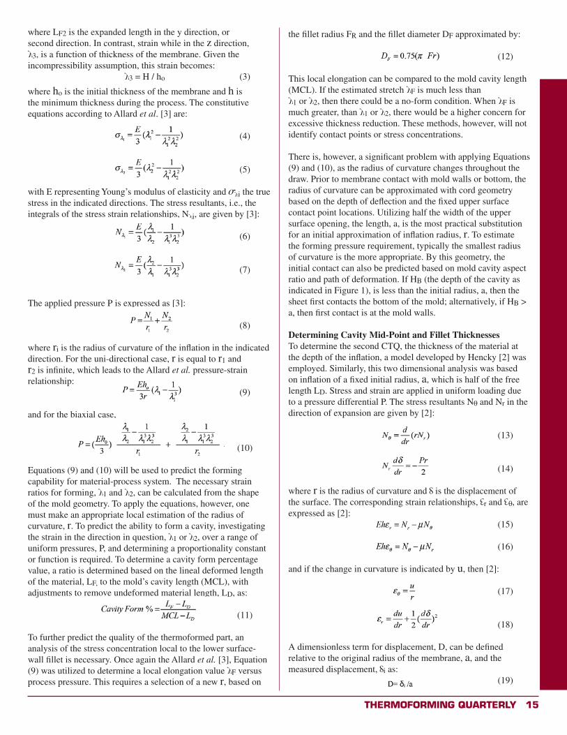
Determining Cavity Formation PercentageThe model developed by Allard et al. [3] was used to predict the forming capability for a material-process system. Developed from the neo-Hookean relationship; it first considered free inflation of the material membrane, not touching mold walls, and then was expanded to make predictions relative to the surfaces of contact. Figure 1 shows the forming process in a two-dimensional schematic with uniform pressure applied to the upper surface of the membrane.
Figure 1. The simple thermoforming model in profile.
In this model, terms are made dimensionless relative to the original free length LD, relative to displacement 3, with strain in the x, or first direction, 1, expressed as: 1.= LF1 / LD (1)where LF1 is the expanded length at any given time within the process. This relationship, called the lineal draw ratio, is commonly used to characterize draw capability [5]. In this work, the first direction was considered the longitudinal or machine direction, and for the woven materials, the warp of the weave. Strain in the y direction (or the transverse direction or weft of the weave), 2, is indicated as: 2 = LF2/LD (2)
Thermoforming QuarTerly 15
where LF2 is the expanded length in the y direction, or second direction. In contrast, strain while in the z direction,
3, is a function of thickness of the membrane. Given the incompressibility assumption, this strain becomes: 3 = H / ho (3)
where ho is the initial thickness of the membrane and h is the minimum thickness during the process. The constitutive equations according to Allard et al. [3] are: (4) (5)
with E representing Young’s modulus of elasticity and i the true stress in the indicated directions. The stress resultants, i.e., the integrals of the stress strain relationships, N i, are given by [3]:
(6)
(7)
The applied pressure P is expressed as [3]:
(8)
where ri is the radius of curvature of the inflation in the indicated direction. For the uni-directional case, r is equal to r1 and r2 is infinite, which leads to the Allard et al. pressure-strain relationship: (9)
and for the biaxial case,
(10)
Equations (9) and (10) will be used to predict the forming capability for material-process system. The necessary strain ratios for forming, 1 and 2, can be calculated from the shape of the mold geometry. To apply the equations, however, one must make an appropriate local estimation of the radius of curvature, r. To predict the ability to form a cavity, investigating the strain in the direction in question, 1 or 2, over a range of uniform pressures, P, and determining a proportionality constant or function is required. To determine a cavity form percentage value, a ratio is determined based on the lineal deformed length of the material, LF, to the mold’s cavity length (MCL), with adjustments to remove undeformed material length, LD, as:
(11)
To further predict the quality of the thermoformed part, an analysis of the stress concentration local to the lower surface-wall fillet is necessary. Once again the Allard et al. [3], Equation (9) was utilized to determine a local elongation value F versus process pressure. This requires a selection of a new r, based on
the fillet radius FR and the fillet diameter DF approximated by:
(12)
This local elongation can be compared to the mold cavity length (MCL). If the estimated stretch F is much less than
1 or 2, then there could be a no-form condition. When F is much greater, than 1 or 2, there would be a higher concern for excessive thickness reduction. These methods, however, will not identify contact points or stress concentrations.
There is, however, a significant problem with applying Equations (9) and (10), as the radius of curvature changes throughout the draw. Prior to membrane contact with mold walls or bottom, the radius of curvature can be approximated with cord geometry based on the depth of deflection and the fixed upper surface contact point locations. Utilizing half the width of the upper surface opening, the length, a, is the most practical substitution for an initial approximation of inflation radius, r. To estimate the forming pressure requirement, typically the smallest radius of curvature is the more appropriate. By this geometry, the initial contact can also be predicted based on mold cavity aspect ratio and path of deformation. If HB (the depth of the cavity as indicated in Figure 1), is less than the initial radius, a, then the sheet first contacts the bottom of the mold; alternatively, if HB > a, then first contact is at the mold walls.
Determining Cavity Mid-Point and Fillet ThicknessesTo determine the second CTQ, the thickness of the material at the depth of the inflation, a model developed by Hencky [2] was employed. Similarly, this two dimensional analysis was based on inflation of a fixed initial radius, a, which is half of the free length LD. Stress and strain are applied in uniform loading due to a pressure differential P. The stress resultants N0 and Nr in the direction of expansion are given by [2]:
(13)
(14)
where r is the radius of curvature and is the displacement of the surface. The corresponding strain relationships, r and 0, are expressed as [2]: (15)
(16)
and if the change in curvature is indicated by u, then [2]:
(17)
(18)
A dimensionless term for displacement, D, can be defined relative to the original radius of the membrane, a, and the measured displacement, i as: (19)
16 Thermoforming QuarTerly
Next, considering a parabolic shape of:
(20)
the maximum deflection becomes: (21)
At this point, the Equations (13) and (14) yield:
(22)
Combining the Equations (15), (18), (20), (21), and (22) produces:
(23)
and the radial displacement u of the radius of curvature becomes:
(24)
Equations (23, 24) are combined to give:
(25)
which, when integrated, yields the Hencky thickness equation used to predict the thickness of the material at maximum inflation:
(26)
For this model to make physical sense, however, the deflection must be in the negative direction. In addition, this relationship is highly sensitive to membrane radius, a. To determine the Poisson’s ratio, μ, experimental data for elongations versus material orientation is required. The relative difference between these elongations quantifies a value of anisotropy and the correction factor relative to the pure isotropic condition.
Osswald [4] later developed an analytical solution for the resulting material thickness based on mold geometry and mass balance; this model is exclusive of the stress-strain modulus and Poisson’s ratio. Starting with a conical shaped cavity draped by the forming material (Figure 1), assumptions are made that the material analyzed is Newtonian, isotropic, incompressible and laminar in flow; all thermophysical factors are constant; the process is a steady state and proceeds at constant velocity; no slip occurs at the upper surface - i.e., the plane of first contact; the process is fully developed, i.e., the material does not draw from along the upper surface (entrance effects are negligible); and gravitational effects were negligible. The conic section is defined by the wall, or draft angle, b, and the depth of the projected cone, H. The contact along the cone’s wall Lw is shown in Figure 1 and its change though the process is expressed as: Lw = Lo + lw, where Lo is the original length and /w is the net change in length. A mass balance is calculated, based on the membrane bubble translation as it advances a distance lw, providing:
(27)
When a= r sin b, the Equation (27) becomes:
(28)
Ultimately, the Osswald thickness equation is solved as:
(29)
Modulus and ThermoformingIn Allard et al.'s model, radial deflection is proportional to perimeter stretch in the membrane. This proportionality is similar to both the tensile and flexural modulus, but different in critical aspects. In uniaxial tensile testing, (ASTM Standard D638-10 [8]), ends are fixed and a no-slip condition exists at the test machine grips, but in thermoforming the force is applied normal to the surface as in flexural testing (ASTM D790-10 [9]). Unfortunately, the flexural testing standard equally cannot be applied in that it is based in that of a simply supported beam with free ends. Another issue is that Allard et al. [3] employed Young’s modulus as the E in their analyses, but this property, by definition does not apply in the ductile plastic range at process conditions [10]. Deformation is also independent of the stiffness and strain hardening of the material by the model [3].
To make a useful algorithm I propose the use of new non-linear modulus function, I call the plastic modulus, Ep, which relates radial strain to lateral stress is hereby proposed. This proportionality constant is akin to the flexural modulus and the strain can be expressed as:
(30)
where k is a stiffness factor and h1, h2, h3 … are strain hardening factors related to the polymer’s molecular structure. E can be determined experimentally by stretching the polymer sheet into an experimental mold over a range of temperatures, pressures and speeds. Restricting independent variables to established process conditions, one can determine practical modulii for thermoforming applications.
ExperimentalTo satisfy the objective to develop a predictive tool a step program was developed for mathematical or spreadsheet software (with the ability to solve for polynomial roots). This algorithm combined the Allard et al., Hencky and Osswald equations for stretch and thickness reduction. Then to evaluate the speed and accuracy of the tool a comparison to a series of single-ply and composite thermoforms was performed.
Materials Several materials were utilized in the validation, single-single ply sheet polyvinyl chloride (PVC) and composite laminations of the PVC as a surface layer with woven two grades of commingled reinforcement layers. Later, several other surface materials were substituted for the PVC to investigate the application of the algorithm across a range of potential laminations utilizing the woven reinforcement component. The single-ply samples were continuously manufactured sheet stock, The reinforcement
Thermoforming QuarTerly 17
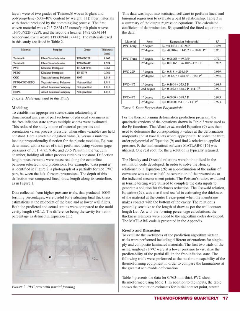
layers were of two grades of Twintex® woven E-glass and polypropylene (60%-40% content by weight [11]) fiber materials with thread produced by the commingling process. The first woven material was a 745 GSM (22 ounce/yard) plain weave TPP60N22P (22P), and the second a heavier 1492 GSM (44 ounce/yard) twill weave TPP60N44T (44T). The materials used in this study are listed in Table 2.
Table 2. Materials used in this Study
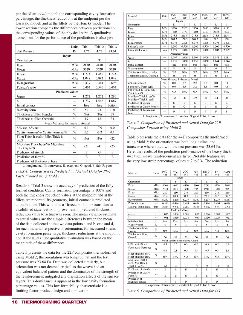
ModelingTo establish an appropriate stress-strain relationship a dimensional analysis of part sections of physical specimens in the free inflation state across multiple widths were evaluated. This reduced the study to one of material properties and orientation versus process pressure, when other variables are held constant. Here a stretch elongation value, , versus a uniform loading proportionality function for the plastic modulus, EP, was determined with a series of trials performed using vacuum gage pressures of 3.31, 4.73, 9.46, and 23.6 Pa within the vacuum chamber, holding all other process variables constant. Deflection length measurements were measured along the centerline between selected mold protrusions. For example, “data point a” is identified in Figure 2, a photograph of a partially formed PVC part, between the left- forward protrusions. The depth of this deflection was compared lineal draw length along its centerline, as in Figure 1.
Data collected from higher pressure trials, that produced 100% forming percentages, were useful for evaluating final thickness estimations at the midpoint of the base and at lower wall fillets. Both the predicted and actual strains were compared to the mold cavity length (MCL). The difference being the cavity formation percentage as defined in Equation (11).
Figure 2. PVC part with partial forming.
This data was input into statistical software to perform lineal and binomial regression to evaluate a best fit relationship. Table 3 is a summary of the output regression equations. The calculated coefficient of determination, R2, quantified the fitted equation to the data.
Table 3. Data Regression Polynomials
For the thermoforming deformation prediction program, the quadratic versions of the equations shown in Table 3 were used as the EP functions. The Allard et al. model Equation (9) was then used to determine the corresponding values at the deformation midpoints and at base fillets where appropriate. To solve the third order polynomial of Equation (9) and find relative to applied pressure, P, the mathematical software MATLAB® [16] was utilized. One real root, for the solution is typically returned.
The Hencky and Osswald relations were both utilized in the estimation code developed. In order to solve the Hencky relationship in Equation (26) an approximation of the radius of curvature was taken as half the separation of the protrusions at the indicated measurement points. The Poisson’s ratios, evaluated in tensile testing were utilized to complete the data inputs to generate a solution for thickness reduction. The Osswald relation, Equation (29), was also found useful in estimating the thickness of the material at the center freeze-point when the membrane makes contact with the bottom of the cavity. The relation is generally sensitive to the length of draw as per the wall contact length Lw. As with the forming percentage calculations, the thickness relations were added to the algorithm codes developed. The MATLAB® code is presented in the Appendix.
Results and DiscussionTo evaluate the usefulness of the prediction algorithm sixteen trials were performed including different orientations for single-ply and composite laminated materials. The first two trials of the using single-ply PVC were at a lower pressure to visualize the predictability of the partial fill, in the free-inflation state. The following trials were performed at the maximum capability of the thermoforming equipment in order to compare the laminations at the greatest achievable deformation.
Table 4 presents the data for 0.763-mm-thick PVC sheet thermoformed using Mold 1. In addition to the inputs, the table shows the prediction estimates for initial contact point, stretch
18 Thermoforming QuarTerly
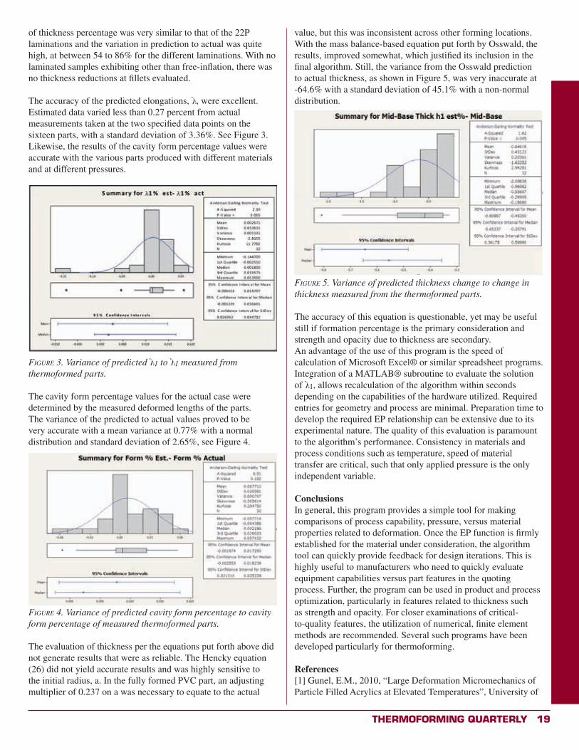
per the Allard et al. model, the corresponding cavity formation percentage, the thickness reductions at the midpoint per the Osswald model, and at the fillets by the Hencky model. The lower section compares the differences between predictions to the corresponding values of the physical parts. A qualitative assessment for the performance of the predictions is also given.
Table 4. Comparison of Predicted and Actual Data for PVC Parts Formed using Mold 1
Results of Trial 3 show the accuracy of prediction of the fully formed condition. Cavity formation percentage is 100% and both the thickness reduction values at the midpoint and at the fillets are reported. By geometry, initial contact is predicted at the bottom. This would be a “freeze point”, or transition to a solidified state, yet no improvement in predicted thickness reduction value to actual was seen. The mean variance estimate to actual values are the simple differences between the mean of the data collected at the two data points a and b, or c and d, for each material respective of orientation, for measured strain, cavity formation percentage, thickness reductions at the midpoint and at the fillets. The qualitative evaluation was based on the magnitude of these differences.
Table 5 presents the data for the 22P composites thermoformed using Mold 2; the orientation was longitudinal and the test pressure was 23.64 Pa. Data was collected similarly, but orientation was not deemed critical as the weave had an equivalent balanced pattern and the dominance of the strength of the reinforcement mitigated any orientation affects of the surface layers. This dominance is apparent in the low cavity formation percentage values. This low formability characteristic is a limiting factor product design and application.
Table 5. Comparison of Predicted and Actual Data for 22P Composites Formed using Mold 2
Table 6 presents the data for the 44T composites thermoformed using Mold 2; the orientation was both longitudinal and transverse where noted with the test pressure was 23.64 Pa. Here, the results of the prediction performance of the heavy thick 44T twill weave reinforcement are listed. Notable features are the very low strain percentage values at 2 to 3%. The reduction
Table 6. Comparison of Predicted and Actual Data for 44T
Thermoforming QuarTerly 19
of thickness percentage was very similar to that of the 22P laminations and the variation in prediction to actual was quite high, at between 54 to 86% for the different laminations. With no laminated samples exhibiting other than free-inflation, there was no thickness reductions at fillets evaluated.
The accuracy of the predicted elongations, , were excellent. Estimated data varied less than 0.27 percent from actual measurements taken at the two specified data points on the sixteen parts, with a standard deviation of 3.36%. See Figure 3. Likewise, the results of the cavity form percentage values were accurate with the various parts produced with different materials and at different pressures.
Figure 3. Variance of predicted 1 to 1 measured from thermoformed parts.
The cavity form percentage values for the actual case were determined by the measured deformed lengths of the parts. The variance of the predicted to actual values proved to be very accurate with a mean variance at 0.77% with a normal distribution and standard deviation of 2.65%, see Figure 4.
Figure 4. Variance of predicted cavity form percentage to cavity form percentage of measured thermoformed parts.
The evaluation of thickness per the equations put forth above did not generate results that were as reliable. The Hencky equation (26) did not yield accurate results and was highly sensitive to the initial radius, a. In the fully formed PVC part, an adjusting multiplier of 0.237 on a was necessary to equate to the actual
value, but this was inconsistent across other forming locations. With the mass balance-based equation put forth by Osswald, the results, improved somewhat, which justified its inclusion in the final algorithm. Still, the variance from the Osswald prediction to actual thickness, as shown in Figure 5, was very inaccurate at -64.6% with a standard deviation of 45.1% with a non-normal distribution.
Figure 5. Variance of predicted thickness change to change in thickness measured from the thermoformed parts.
The accuracy of this equation is questionable, yet may be useful still if formation percentage is the primary consideration and strength and opacity due to thickness are secondary. An advantage of the use of this program is the speed of calculation of Microsoft Excel® or similar spreadsheet programs. Integration of a MATLAB® subroutine to evaluate the solution of 1, allows recalculation of the algorithm within seconds depending on the capabilities of the hardware utilized. Required entries for geometry and process are minimal. Preparation time to develop the required EP relationship can be extensive due to its experimental nature. The quality of this evaluation is paramount to the algorithm’s performance. Consistency in materials and process conditions such as temperature, speed of material transfer are critical, such that only applied pressure is the only independent variable.
ConclusionsIn general, this program provides a simple tool for making comparisons of process capability, pressure, versus material properties related to deformation. Once the EP function is firmly established for the material under consideration, the algorithm tool can quickly provide feedback for design iterations. This is highly useful to manufacturers who need to quickly evaluate equipment capabilities versus part features in the quoting process. Further, the program can be used in product and process optimization, particularly in features related to thickness such as strength and opacity. For closer examinations of critical-to-quality features, the utilization of numerical, finite element methods are recommended. Several such programs have been developed particularly for thermoforming.
References[1] Gunel, E.M., 2010, “Large Deformation Micromechanics of Particle Filled Acrylics at Elevated Temperatures”, University of
20 Thermoforming QuarTerly
Buffalo Electronic Packaging Laboratory Publications, p. 78.
[2] Fichter, W.B., 1997, “Some Solutions for the Large Deflections of Uniformly Loaded Circular Membranes,” NASA Technical Paper No. 3658, Langley Research Center, Hampton Virginia, pp. 1-20.
[3] Allard, R., Charrier, J.M., Ghosh, A., Marangou, M., Ryan, M.E., Shirivastava, S., Wu, R., 1986, “An Engineering Study of the Thermoforming Process: Experimental and Theoretical Considerations”, Journal of Polymer Engineering,” 6, (1-4), pp. 363–394
[4] Osswald, T.A., Hernandez-Ortiz, 2006, Polymer Processing: Modeling and Simulation, Hanser Publishers, Munich, Germany
[5] Throne, J., 2005, “The Ubiquitous Draw Ratio”, Thermoforming Quarterly, SPE, 24, (4), p. 36.
[6] Berins, M.L., 1991, SPI Plastics Engineering Handbook of the Society of the Plastics Industy, Inc. 5th Edition. Springer-Verlag, Germany
[7] Thompson, R., and Stack, R., 2013, “Failure Mode Effect Analysis: Thermoforming,” Hasbro, Inc., Report of Manufacturing Site Team.
[8] ASTM D638-10, 2010, “Standard Test Method Tensile Properties of Plastics”, ASTM International, West Conshohocken, PA, www.astm.org
[9] ASTM D790-10, “Standard Test Method Flexural Properties of Unreinforced and Reinforced Plastics and Electrical Insulating Materials”, ASTM International, West Conshohocken, PA, www.astm.org
[10] Nielsen, L.E. and Landel, R.F., 1994, Mechanical Properties of Polymers and Composites, 2nd Edition, CRC Press, Taylor & Francis Group, Boca Raton FL, p.7
[11] Fiber Glass Industries, 2010, “GLASS POLYPRO MSDS Rev. A, Effective Date: February 17, 2010”
[12] ASTM Standard D882-10, 2010, "Standard Test Method for Tensile Properties of Thin Plastic Sheeting,” ASTM International, West Conshohocken, PA, www.astm.org.
[13] ASTM Standard D638-10, 2010, "Standard Test Method for Tensile Properties of Plastics,” ASTM International, West Conshohocken, PA, www.astm.org.
[14] ASTM D3039/D3039M-08, 2008, “Standard Test Method for Tensile Properties of Polymer Matrix Composite Materials”, ASTM International, West Conshohocken, PA, www.astm.org.
[15] Baumeister, T., Editor, 1958, Mechanical Engineers Handbook, McGraw-Hill Book Company, New York, p.5-63.
[16] The Math Works, 1992, The Student Edition of MATLAB®
for MS-DOS personal computers, Prentice Hall, Englewood Cliffs, NJ.
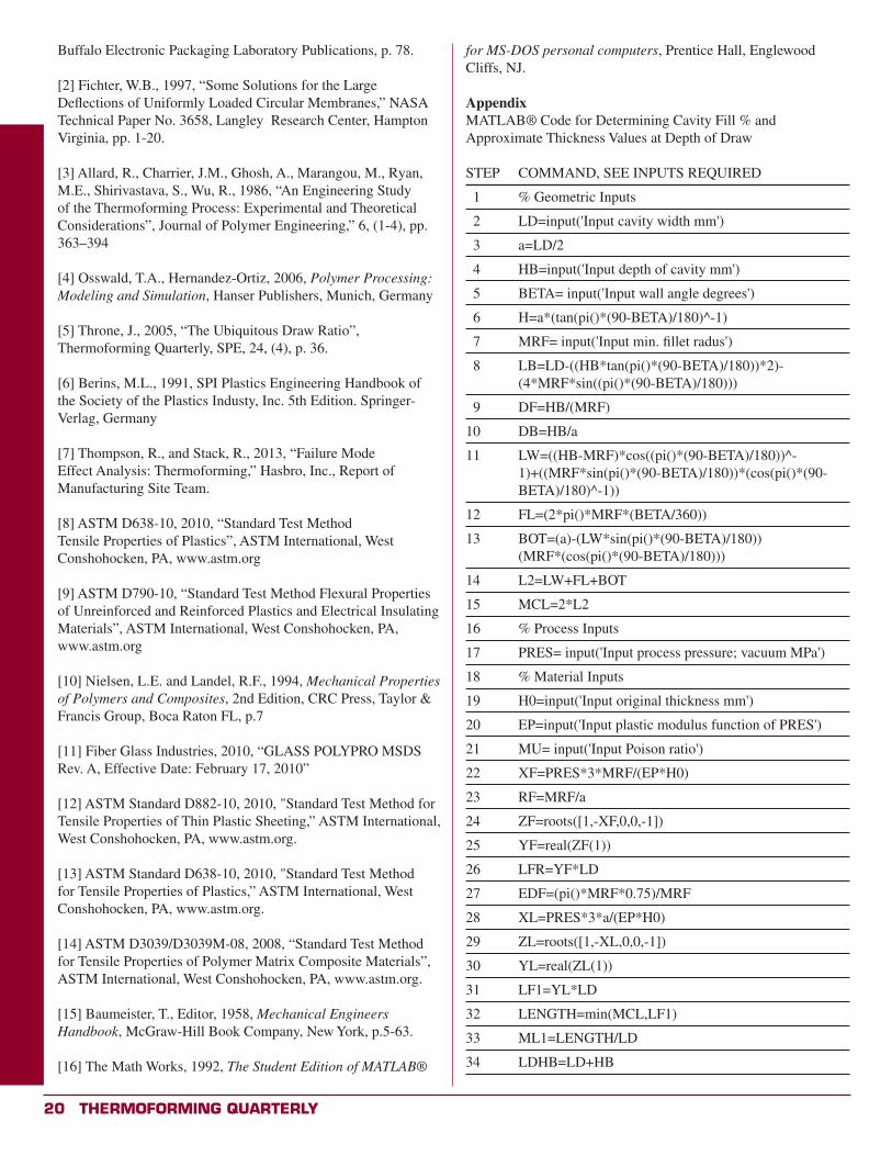
AppendixMATLAB® Code for Determining Cavity Fill % and Approximate Thickness Values at Depth of Draw
STEP COMMAND, SEE INPUTS REQUIRED
1 % Geometric Inputs
2 LD=input('Input cavity width mm')
3 a=LD/2
4 HB=input('Input depth of cavity mm')
5 BETA= input('Input wall angle degrees')
6 H=a*(tan(pi()*(90-BETA)/180)^-1)
7 MRF= input('Input min. fillet radus')
8 LB=LD-((HB*tan(pi()*(90-BETA)/180))*2)- (4*MRF*sin((pi()*(90-BETA)/180)))
9 DF=HB/(MRF)
10 DB=HB/a
11 LW=((HB-MRF)*cos((pi()*(90-BETA)/180))^- 1)+((MRF*sin(pi()*(90-BETA)/180))*(cos(pi()*(90- BETA)/180)^-1))
12 FL=(2*pi()*MRF*(BETA/360))
13 BOT=(a)-(LW*sin(pi()*(90-BETA)/180)) (MRF*(cos(pi()*(90-BETA)/180)))
14 L2=LW+FL+BOT
15 MCL=2*L2
16 % Process Inputs
17 PRES= input('Input process pressure; vacuum MPa')
18 % Material Inputs
19 H0=input('Input original thickness mm')
20 EP=input('Input plastic modulus function of PRES')
21 MU= input('Input Poison ratio')
22 XF=PRES*3*MRF/(EP*H0)
23 RF=MRF/a
24 ZF=roots([1,-XF,0,0,-1])
25 YF=real(ZF(1))
26 LFR=YF*LD
27 EDF=(pi()*MRF*0.75)/MRF
28 XL=PRES*3*a/(EP*H0)
29 ZL=roots([1,-XL,0,0,-1])
30 YL=real(ZL(1))
31 LF1=YL*LD
32 LENGTH=min(MCL,LF1)
33 ML1=LENGTH/LD
34 LDHB=LD+HB
Thermoforming QuarTerly 21
35 % WC=0: FREE, WC=1: BOTTOM, WC=2: WALL
36 WCL=LENGTH*LW/MCL
37 if HB<a
38 WC= 1
39 else
40 WC=2
41 end
42 if LF1<LDHB
43 WC=0
44 WCL=0
45 end
46 % PCF=PERCENT CAVITY FILL
47 PCF=(LENGTH-LD)/(MCL-LD)
48 if PCF>=1
49 HENCKYP=1/(1-(4*EP*H0*(-EDF^3)*(MRF^2)) /((1-MU)*PRES*((MRF)^6)))
50 HENCKYT=H0*HENCKYP
51 end
52 OSSWALDP=((1+cos(pi()*(BETA)/180))/2)*((1- ((WCL/H)*sin(pi()*(BETA)/180)))^((cos(pi()*(BETA) /180)^-1)-1))
53 OSSWALDT=H0*OSSWALDP x
From the EditorIf you are an educator, student or advisor in a college or university with a plastics program, we want to hear from you! The SPE Thermoforming Division has a long and rich tradition of working with academic partners. From scholarships and grants to workforce development programs, the division seeks to promote a stronger bond between industry and academia.
Thermoforming Quarterly is proud to publish news and stories related to the science and business of thermoforming:
• New materials development• New applications• Innovative technologies• Industry partnerships• New or expanding laboratory facilities • Endowments
We are also interested in hearing from our members and colleagues around the world. If your school or institution has an international partner, please invite them to submit relevant content. We publish press releases, student essays, photos and technical papers. If you would like to arrange an interview, please contact Conor Carlin, Editor, at [email protected] or 617-771-3321.
Are You ?
Group Name:Thermoforming Division,
a subgroup of SPE
Moderator:Mark Strachan
Trending Topics(as of November 11, 2013)
1. Thermoformed Planters vs.
Rotationally Molded Planter
2. Formation of new thermoforming
division in India
With over 900 members and growing,
the Thermoforming Division is using Linkedin to expand
the conversation. Meet fellow professionals,
ask tough technical questions, explore related groups.
Join us today!
22 Thermoforming QuarTerly
ThermoformingQuarterly® Industry Practice
Lean Manufacturing Makes Formed Plastics More CompetitiveA CASE STUDY IN EFFICIENCY
By Ron Joannou, Jr. and Steve Zamprelli
In April 2012, Formed Plastics held a Kaizen event consisting of an eight-person panel drawn from different areas of the company. The panel included the VP of Manufacturing, the Executive VP, the Senior Manufacturing Engineer, the fabrication supervisor, the thermoforming foreman, a thermoforming operator, a machinist, and an industrial engineer from LIFT, an outside consulting group. The goal was to decreasing setup times on two machines, a thermo/pressure forming 5’ X 5’ shuttle machine and a thermo/pressure forming 4’ X 8’ machine.
The first step was to measure the duration of the current setup process. We decided to record an average setup for a male vacuum form mold. The mold had heaters and was installed on the upper platen of the 4’ x 8’ shuttle machine. The setup was performed by the foreman of the thermoforming department. The results were amazing.
Upon completion, we had recorded over four hours (251 minutes) of setup time, including 221 steps. As we watched the foreman working as hard as he could for the entire length of the recording, it became immediately clear that lack of effort was not the problem. Rather, the video validated what we had guessed but never truly understood: our current mold setup system was an enormous drag on our operation. There was obviously a lot of room for improvement. As we reviewed the footage, each member of the panel made individual notes on Post-It notes, specifying anything that seemed wrong or any steps that could be eliminated. We also wrote down any other suggestions that we thought might help. We then grouped all of our Post-Its into appropriate categories and placed them on the conference room wall. By the time we were finished, the entire wall was covered in yellow notes. After lengthy discussion, we itemized the key problem areas on a spreadsheet and assigned a level of difficulty to each category.
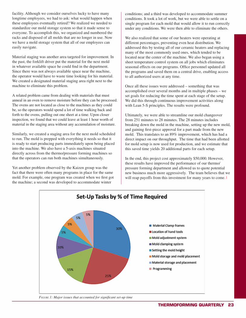
We identified the following major issues that accounted for a significant portion of the setup time (see Figure 1).
The first issue we tackled was the material clamp frame system, which was the original system that came with the machine. Whenever the operator needed to make adjustments, he had to lie on his back to connect air lines. It was cumbersome at best.
What was the solution? As regular attendees of the SPE Annual Thermoforming Conference, we remembered seeing at least two of the major machine manufacturers come up with a new quick
adjustment clamp frame system. We bought two sets and had them installed in our machines for $26,000. The price was hefty, but the payoff was great: what had been taking more than an hour now takes about 5 minutes.
Next, we knew we needed to address the amount of time our operator spent away from the machine, gathering his tools. We built a “Lean Board” that included every tool the operator might need and installed it within arm’s length. We also placed magnetic bowls nearby to hold small pieces of hardware needed for the setup. With this system in place, the operator has no reason to walk away from the machine. Moreover, the new clamp frame system decreased the amount of tools the operator needed.
The third issue we addressed was the mold clamping system.We bought ½” sheets of aluminum plate for the top and bottom platens. We machined equally-spaced threaded holes in a diagonal pattern which facilitated easy clamping of molds regardless of their size. We then bought Lenzke clamps for the quick connect system. We found that these clamps were ideal for holding all types of molds and they were very user-friendly. This cost about $5,000.
The large amount of time spent adjusting the position of molds in the machine was another major source of inefficiency. To fix this, we created a system that ensured every mold would fit exactly in the center of the machine on a protrusion located on either platen, always centered and squared. This eliminated the need to manually locate the mold with a tape measure for each setup. The new clamp frame system is designed to align automatically with the mold that is centered on the machine.
Connecting heaters and water lines was another problem area, so we had the electrician install a quick-connect running from the heater box to the mold. The result: no more dangling wires, and no more time spent searching for connections. Similarly, the plumber installed quick-connects on all water connections and made all air pressure controls and shut-off valves accessible from the front of the machine. Now the operator has full control at his station and does not need to leave the machine during the setup.
The next challenge was to reduce the amount of time spent setting the mold height. Since the machines do not automatically remember the height of our molds, the mold height must be set manually during each setup. To address this, we determined the correct height for each mold and cut a piece of wood (spacer) to that exact figure. Now, we can use this spacer for all future setups. We store it by screwing it to its own vacuum box.
Mold storage was the next issue we tackled. Only a select few veteran employees knew the location of the molds in the storage
Thermoforming QuarTerly 23
facility. Although we consider ourselves lucky to have many longtime employees, we had to ask: what would happen when these employees eventually retired? We realized we needed to standardize our mold storage system so that it made sense to everyone. To accomplish this, we organized and numbered the racks and disposed of all molds that are no longer in use. Now we have a mold storage system that all of our employees can easily navigate.
Material staging was another area targeted for improvement. In the past, the forklift driver put the material for the next mold in whatever available space he could find in the department. Since there was not always available space near the machine, the operator would have to waste time looking for his material. We created a designated material staging area right next to the machine to eliminate this problem.
A related problem came from dealing with materials that must anneal in an oven to remove moisture before they can be processed. The ovens are not located as close to the machines as they could be, so the operators would spend a lot of time walking back and forth to the ovens, pulling out one sheet at a time. Upon closer inspection, we found that we could leave at least 1 hour worth of material in the staging area without any accumulation of moisture.
Similarly, we created a staging area for the next mold scheduled to run. The mold is prepped with everything it needs so that it is ready to start producing parts immediately upon being placed into the machine. We also have a 5-axis machines situated directly across from the thermo/pressure forming machines so that the operators can run both machines simultaneously.
Yet another problem observed by the Kaizen group was the fact that there were often many programs in place for the same mold. For example, one program was created when we first got the machine; a second was developed to accommodate winter
Figure 1: Major issues that accounted for significant set-up time
conditions; and a third was developed to accommodate summer conditions. It took a lot of work, but we were able to settle on a single program for each mold that would allow it to run correctly under any conditions. We were then able to eliminate the others.
We also realized that some of our heaters were operating at different percentages, preventing even heat distribution. We addressed this by testing all of our ceramic heaters and replacing many of the most commonly used ones, which tended to be located near the center of the machine. We also began using a sheet temperature control system on all jobs which eliminates seasonal effects on our programs. Office personnel updated all the programs and saved them on a central drive, enabling access to all authorized users at any time.
Once all these issues were addressed – something that was accomplished over several months and in multiple phases – we set goals for reducing the time spent at each stage of the setup. We did this through continuous improvement activities along with Lean 5-S principles. The results were profound.
Ultimately, we were able to streamline our mold changeover from 251 minutes to 28 minutes. The 28 minutes includes breaking down the mold in the machine, setting up the new mold, and gaining first-piece approval for a part made from the new mold. This translates to an 89% improvement, which has had a direct impact on our throughput. The time that had been allotted for mold setup is now used for production, and we estimate that this saved time yields 20 additional parts for each setup.
In the end, this project cost approximately $50,000. However, these results have improved the performance of our thermo/pressure forming department and allowed us to quote potential new business much more aggressively. The team believes that we will reap payoffs from this investment for many years to come. x
24 Thermoforming QuarTerly
ThermoformingQuarterly® Industry Practice
Cause and Effect Considerations of Mold Materialsby Roger C. Kipp, Kipp & Associates
The question of mold materials and resulting temperature control relating to the production of sheet fed thermoforming provides for some interesting discussion.
To achieve the highest quality, dimensionally-consistent parts at the most efficient production rates, temperature controlled aluminum molds must be used. However, the use of epoxy, urethanes, polyester FRP, ceramic or other materials can be used for special forming projects, short runs and prototypes.
Accurate information regarding the cause and effect on engineering processing parameters will provide a better understanding of the impact of non-temperature controlled tooling on the forming process. This report is an accumulation of information gathered from communications with a number of leaders in the thermoforming industry, from practical experience and experimental data completed at Pennsylvania College of Technology, Thermoforming Center of Excellence.
With accurate information and data decision makers utilizing the thermoforming process can determine under which circumstances to consider non temperature controlled tooling. With this information documented achievable expectations and specifications can be defined between the processor, material supplier and thermoforming component purchaser.
Where are the effects relating to varying mold material?• Heat transfer• Durability• De-molding• Surface finish• Physical properties• Dimensional accuracy
How will variability in these factors impact quality and productivity in thermoforming? Heat TransferUnder ideal circumstances proper mold temperature for the given material will be maintained throughout the run. Data supports that the hotter the mold the more the final shrinkage of the part. Also a cold mold results in internal stresses that are left in the part and can result in future stress cracking. Temperature controlled molds are designed to maintain a mold temperature within a Delta 5 degrees span. Most of the heat absorbed by the material during the heating cycle must be extracted before the part can be removed from the mold. Non temperature controlled molds will act as a heat sink and become hotter during processing
and less effective in transferring heat. These heat/temperature variables have the following impact:
• With non temperature control.*o When the heat is not evenly removed distortion or
warp can occur in the part. Secondary fixtures for post curing and minimization of warp will be necessary.
o The parts will reveal less dimensional stability resulting in varying tolerance throughout the run. Experimental data shows that parts produced from a non temperature controlled molds exhibit less consistent dimensional accuracy.
o Due to heat build up in the mold cycle times are longer due to increased cooling time for the part and the mold. Longer cycle times result in higher forming costs.
• With temperature controlled molds.*o Tighter dimensional tolerance and consistent
processing.o Less shrink and control of distortion and warp out of
the mold.o Mold temperature control leads to less cooling time and
maximum efficiency.
Dimensional Accuracy• The heat sink properties of the non-temperature controlled molds results in varying mold temperatures throughout the run. This will lead to dimensional variation and warp that will need to be considered in the tolerance specifications.*
*Testing conducted at the Pennsylvania College of Technology Thermoforming Center of Excellence and published in the SPE Thermoforming Quarterly, Second Quarter 2011.
DurabilityThermoform tooling is exposed to a continuing cycling of heat absorption. How does this impact the tooling?
• With non temperature controlled tooling.o These heat cycles gradually breakdown the mold
material. Add to this the friction or drag experienced with part removal and mold damage eventually becomes evident resulting in possible quality surface defects and production interruption as well as added tooling repair costs.
o Prolonged heat cycling will result in crazing of composite material and delaminating in tooling board or wood molds. This damage will result in mark off transferred to the part, subsequent mold failure and the need for replacement.
• With aluminum temperature controlled tools.o The mold experiences a controlled heat/cool cycle
maintaining the mold material well below its softening
Thermoforming QuarTerly 25
stage. Therefore aluminum tooling has no limited life due to heating impact.
De-MoldingWith a positive mold the material shrinkage will tighten the part on the mold. Process control needs to be maintained to remove the part before it “strangles” the mold due to thermal shrinkage making removal difficult.
• With non temperature controlled tooling.o The part may remain on the mold longer furthering
the shrink to the mold surface. A release agent must be applied to help with the part release. However part distortion and warp still may result.
• With temperature controlled molds.o No release agent is necessary and the part will be
sufficiently cooled on the mold to avoid distortion during the part removal.
Surface FinishCosmetics relating to surface imperfections and surface preparation of the mold are affected by mold material.
• Non temperature controlled mold materials.o Can not be polished for a highly cosmetic part finish.o Imperfections due to mold ware such as crazing and
cracking will transfer through to the part surface.o Uneven and non controlled mold temperature resulting
from non temperature controlled tooling will not maintain the mold at a temperature close to plastic solidification. This will result in chill marks or abrupt steps in the wall material thickness.
• The aluminum temperature controlled mold;o Can be polished or sand blasted for the necessary finish
and air evacuation.o The aluminum is a harder durable surface that will not
craze or crack over time.
Physical PropertiesThe difference in thickness, cooling rate, and cooling time across the part surface may lead to different thermal stresses in the final part. These different thermal stresses, together with different degrees of stretching in the part during forming and de-molding can lead to warping, uneven shrinkage and stress cracking.
• In non temperature controlled molds;o Due to build up of heat in the mold the parts at the
beginning of the run will have different levels of stress than those at the end of the run. Thus the production will yield parts with varying physical properties.
o There is not even cooling. Ideally the part should be cooled evenly across the surface and on both sides to yield the most stress free part. Stress free parts will maintain their shape when subjected to heat in the environment and are not subject to cracking due to residual stress.
* Testing is currently being conducted at the Pennsylvania College of Technology Thermoforming Center of Excellence to determine the effect on mechanical properties from processing with non-temperature controlled tooling.
How do the variables in these mold materials impact processing considerations?
• Non temperature control molds.o Lack of process controls; you can’t control what you
can’t measure.o Additional fixtures required to minimize warp issues.o Added tooling maintenance; production interruption
and quality impact.o Added processing time; cycle time, quality waste, start
up loss and set up time.o Trim fixture fitment variables due to varying part
dimensions related to inconsistent shrink caused by varying mold temperature.
Under what circumstances non temperature controlled molds could be considered?
• Prototype• Low volume requirements; up to 100 pieces
o This is affected by part geometry; simple shapes with abundant draft will yield greater numbers.
o Material thickness is also a factor; less than .125 starting gage can often run effectively on non temperature controlled tooling.
• Open tolerances can be specified.• The component is non cosmetic; including acceptance
of chill marks.• An understanding for the potential of on going mold
repair and replacement is in place.• The component will not be under a load or in stress.• Longer cycle times, from 15% to 30% depending on
material and gage, are acceptable.
Here are some related comments from the discussions with industry contacts.
• There is a lot of inaccurate information out there communicated to “just get the work” and not based on fact.
• “In Europe, machined tooling board is used for prototype and production up to 100 pieces.”
• “In the end after all things are considered (high density tooling board, labor, resin tooling surface coat, and production efficiency loss) the total cost is comparable to aluminum.”
• “80% of processing problems are temperature related.” So why take away the opportunity to measure and manage a temperature variable?
• “We have seen success in forming TPO using ceramic molds with multiple post curing fixtures. This would be limited to low production and non cosmetic parts.”
Communication is the key. There are circumstances where non-temperature controlled tooling can be acceptable. However it is critical that there is clear understanding with the quality team, engineering and marketing of the capabilities when agreeing to the loss of temperature control. Expectations and specification adjustments will need to be defined and documented for each application. x

26 Thermoforming QuarTerly
ThermoformingQuarterly® New Members
Heshmat AglanTuskegee University
Michael BarnesRe-Bath LLC
Marco Bellotti CMG America Inc.
David Bogenhagen Airworthy Aerospace
Rick BurntonAspen Research
Paul Cassady Rocktenn Company David ChouProphotosynthetics
Qinghui ChuMytex Polymers
Clive Copsey Sabert
Will DickeyKlockner Pentaplast
Joseph DykeInline Plastics Stefan EbertuVu Technologies
Randy Gardiner Directed Energy
David GeeIHS
Steve Goldsmith Wearwell
David A. GrauCardPak
Brant HarperWashington Penn Plastic Company, Inc.
Mark D. HasselbachBrookdale Plastics, Inc.
Stephen HenkelLegend Brands
Brad HillierRe-Bath LLC
Mark Jackson Ocean Equipment
Steve Jalbert Pelican International
Tina Jones OSSID
Michael Kase Brentwood Industries
Danielle Kienle Brentwood Industries
Edward LengenMuli-Plastics Extrusions Inc.
Michael LoweryPremier Plastics
Steve LutesAmpacet
Dipak MankodiBerconia Pty. Ltd.
Vittorio MartelliCMG America Inc.
Vincent McWhorter Aristech Acrylics
Sean MonahanFabri-Kal
Stephen MooreOrion Plastics Inc.
Amanda MullenburgDow Chemical
German MunozMedios Impresos SI
Lisa Ontjes Battenfeld Cincinnati USA
Martin PelchatPlastik M.P.
George PickardAeroklas Company Limited
Mindaugas Rackaitis Bridgestone
Al RussoCNC Router Exchange (a division of CNC Parts Dept.)
Paul Salvisburg Vulcan Plastics Technology Company, Ltd.
Mark Schweitzer Airworthy Aerospace
Mark SmallUPPI
Louis SmithSAY Plastics Inc.
Sheridan Sparrow LINDAR Corp.
Jake Stephany Wilbert Plastic Services
Curtis StognerBoltaron
Paul ThompsonDrader Manufacturing
Ekawat Vitorapkor Aeroklas
Dustin Wagner Plastic Ingenuity
Mark O. White Plastic Solutions
Abiy WudahDrader Manufacturing
Thermoforming QuarTerly 27
28 Thermoforming QuarTerly
ThermoformingQuarterly® Thermoforming 2.0
Heating and Cooling the SheetBy Dr. Joseph E. LeBlanc, Pennsylvania College of TechnologyWilliamsport, PA
The initial step in thermoforming is to heat the sheet, and the aim is to heat the core to the forming temperature in the shortest time without overheating the surface. The appropriate method will depend on the type of plastic and the thickness of the sheet. Every material has its own properties that will determine how fast or slow the heat will penetrate, and how much heat you will need to increase its temperature. These properties are controlled by the molecular structure of the material, with a big difference between metals, ceramics, and polymers.
The parameters that characterize heat transfer are the following:
Thermal conductivity indicates how easy heat will move. There are two main types of materials: conductors and insulators. Plastics fall in the insulators category, which works against us. Typically a good conductor of electricity is also a good conductor of heat because they are both carried by the electrons themselves, but in plastics the heat is transferred by molecular vibrations, and there is little transfer across the links between polymers, so it makes for a slow motion of heat.
Specific Heat Capacity measures how much heat you need to raise the temperature of an object. Heat in metals is stored in the electronic energy levels, and this easily translates into a higher temperature. Heat in polymers is stored in molecular vibrations and it makes it harder for the polymers to express that energy in the form of higher temperature, therefore they have a higher specific heat capacity, and that is another problem to face in preparing them for thermoforming.
The quantities of density, conductivity, and specific heat capacity are combined into a new quantity called Thermal Diffusivity, which measures the “thermal inertia” of a material. We can understand it as how fast the temperature changes when heat is pumped into an object. The word diffusion describes how molecules can move into another material by the random motions they constantly experience. If the molecules are light and fast they will diffuse quickly, and similarly the increase in temperature will diffuse quickly into an object with low density, high conductivity, and low heat capacity. Polymers have a disadvantage compared to metals.
The modes of transferring heat into the material are Conduction, Convection, and Radiation. Let’s review these briefly.
Conduction will move heat within a solid. It will also move the
heat into the solid and out of the solid into a fluid, which can be a gas or a liquid. Thus, when a gas comes in touch with a solid, the method of heat transfer from the solid out to the gas is conduction. Two solids must be in absolute contact for the heat to transfer and even a small gap will prevent conduction from happening. This is a common problem in computers that have to cool down the CPU with a heat sink. They use a paste to couple the two surfaces, or the CPU will overheat and self-destruct. Once a fluid has been heated or cooled (by conduction) it will naturally move away because of buoyancy forces and form a natural convection current. Hot gases rise and cool gases sink. If the fluid is pushed by a fan it is called a forced convection current and it is typically much more effective in moving heat than natural convection. The reason is that a layer of heated gas will form over the surface of the solid and will insulate the solid from the rest of the gas at a greater distance. This is called a boundary layer, and it is crucial in understanding the behavior of any fluid in contact with a solid. The boundary layer is always present on the surface of the solid because the first layer of molecules of the fluid stick to the solid and remain stuck. The next layer will slide over the first layer, and the following layers will slide more easily. The thickness of the boundary layer will depend on the viscosity of the fluid. This phenomenon is true for air, water, engine oil, paint, and liquid detergents, and is crucial in allowing airplanes to fly and in maintaining the lubrication of all parts in your car engine. Radiation is the energy emitted by every object at any temperature, not just when it is “warm”, but at any temperature every object is emitting some amount of electromagnetic radiation. The amount, rate, and wavelength of that radiation will depend mainly on the temperature of the object, given in Kelvin. The rate of heat emitted depends on the fourth power of the temperature (Stefan-Boltzmann Law), so radiation varies dramatically with changes in temperature. Consider that doubling the temperature will produce 16 times more wattage (24 = 16). This makes infrared cameras able to detect small changes in temperature, as you can see in many examples of infrared thermography. The energy emitted by an object will not have a single wavelength, but will have a spread, and a perfect emitter will have a spectrum called a Blackbody Spectrum. This spectrum has a peculiar distribution (Planck’s Law) with a peak around which most of the radiation energy output is concentrated, and much lesser amounts around it as shown in the Figure. The peak is determined by the temperature and is described by Wien’s Displacement Law. Most radiators are not blackbodies and will have a different spectral distribution, but the basis for comparisons and calibration is the blackbody (see Figure 1).
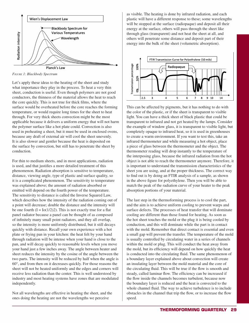
Thermoforming QuarTerly 29
Let’s apply these ideas to the heating of the sheet and study what importance they play in the process. To heat a very thin sheet, conduction is useful. Even though polymers are not good conductors, the thinness of the material allows the heat to reach the core quickly. This is not true for thick films, where the surface would be overheated before the core reaches the forming temperature, or would require long times for the sheet to heat through. For very thick sheets convection might be the most applicable because it delivers a uniform energy that will not harm the polymer surface like a hot plate could. Convection is also used in preheating a sheet, but it must be used in enclosed ovens, because any draft of external air will cool the sheet unevenly. It is also slower and gentler because the heat is deposited on the surface by convection, but still has to penetrate the sheet by conduction.
For thin to medium sheets, and in most applications, radiation is used, and that justifies a more detailed treatment of this phenomenon. Radiation absorption is sensitive to temperature, distance, viewing angle, type of plastic and surface quality, so it is a complicated phenomenon. The sensitivity to temperature was explained above; the amount of radiation absorbed or emitted will depend on the fourth power of the temperature. The sensitivity to distance is called the Inverse Squared Law, which describes how the intensity of the radiation coming out of a point will decrease; double the distance and the intensity will be one fourth (I = Io(1/2)2). This is not exactly true for a flat panel radiator because a panel can be thought of as composed of infinitely many small point radiators, and they all overlap, so the intensity is more uniformly distributed, but it still decays quickly with distance. Recall your own experience with a hot plate or frying pan in your kitchen: the heat felt by your hand through radiation will be intense when your hand is close to the pan, and will decay quickly to reasonable levels when you move your hand just a few inches away. The angle between heater and sheet reduces the intensity by the cosine of the angle between the two parts. The intensity will be reduced by half when the angle is 60°, and from then on it decreases quickly. For those reasons the sheet will not be heated uniformly and the edges and corners will receive less radiation than the center. This is well understood by industry and most heating systems have zones that are modulated independently.
Not all wavelengths are effective in heating the sheet, and the ones doing the heating are not the wavelengths we perceive
as visible. The heating is done by infrared radiation, and each plastic will have a different response to these; some wavelengths will be stopped at the surface (radiopaque) and deposit all their energy at the surface, others will pass through the sheet like through glass (transparent) and not heat the sheet at all, and others will penetrate some distance and deposit part of their energy into the bulk of the sheet (volumetric absorption).
This can be affected by pigments, but it has nothing to do with the color of the plastic, or if the sheet is transparent to visible light. You can have a thick sheet of black plastic that could be transparent to infrared and not get heated by the lamps. Consider the example of window glass, it is transparent to visible light, but completely opaque to infrared heat, so it is used in greenhouses to create a warm environment. If you want to test this, take an infrared thermometer and while measuring a hot object, place a piece of glass between the thermometer and the object. The thermometer reading will drop instantly to the temperature of the interposing glass, because the infrared radiation from the hot object is not able to reach the thermometer anymore. Therefore, it is important to understand the transmission characteristics of the sheet you are using, and at the proper thickness. The correct way to find out is by doing an FTIR analysis of a sample, as shown in the above figure for polyethylene. Then you will be able to match the peak of the radiation curve of your heater to the peak absorption portions of your material.
The last step in the thermoforming process is to cool the part, and the aim is to achieve uniform cooling to prevent warps and surface defects. The processes of heat transfer that will dominate cooling are different than those found for heating. As soon as the hot sheet touches the mold or the plug it is being cooled by conduction, and this will dominate while the part is in contact with the mold. Remember that direct contact is essential and even a small gap will prevent the transfer. The temperature of the mold is usually controlled by circulating water in a series of channels within the mold or plug. This will conduct the heat away from the mold, but its efficiency will depend on how quickly the heat is conducted into the circulating fluid. The same phenomenon of a boundary layer explained above about convection will create an insulating layer between the mold material and the core of the circulating fluid. This will be true if the flow is smooth and steady, called laminar flow. The efficiency can be increased if the flow inside the channels becomes turbulent, because now the boundary layer is reduced and the heat is convected to the whole channel fluid. The way to achieve turbulence is to include obstacles in the channel that trip the flow, or to increase the flow speed.
Figure 1: Blackbody Spectrum

30 Thermoforming QuarTerly
When the part is separated from the mold the convection currents over the part will dominate the cooling, and forced convection is much more effective than natural convection. At this point radiation is minimal because of the relatively low temperature, remember the dependence on the fourth power of the temperature, and the mold has already cooled the part before separating. Cooling the part is slower than heating the sheet, both because the mechanisms are more restricted and because it must be controlled to achieve good results.
ReferencesTechnology of Thermoforming, James L. Throne, Hanser/Gardner
Publications, 1996
Thermoforming, G. Gruenwald, Technomic Publishing Co., 1998
Transactions in Measurement and Control, Volume 1, 3rd Edition, Omega Engineering Inc., 2004, Putman Publishing Company and OMEGA Press LLC, www.omega.com
Radiant Heating with Infrared, a Technical Guide to Understanding and Applying Infrared Heaters, Watlow Electric Manufacturing Company, 1999, www.watlow.com x
Why Join?
Why Not?
It has never been more
important to be a member of
your professional society than
now, in the current climate of
change and volatility in the
plastics industry. Now, more
than ever, the information
you access and the personal
networks you create can
and will directly impact your
future and your career.
Active membership in SPE
– keeps you current, keeps
you informed, and keeps you
connected.
The question really
isn’t “why join?”
but …
®

Thermoforming QuarTerly 31
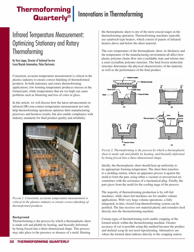
32 Thermoforming QuarTerly
ThermoformingQuarterly® Innovations in Thermoforming
the thermoplastic sheet is one of the most crucial stages in the thermoforming operation. Thermoforming machines typically use sandwich-type heaters, which consist of panels of infrared heaters above and below the sheet material.
The core temperature of the thermoplastic sheet, its thickness and the temperature of the manufacturing environment all affect how plastic polymer chains flow into a moldable state and reform into a semi-crystalline polymer structure. The final frozen molecular structure determines the physical characteristics of the material, as well as the performance of the final product.
Figure 2. Thermoforming is the process by which a thermoplastic sheet is made soft and pliable by heating, and biaxially deformed by being forced into a three-dimensional shape.
Ideally, the thermoplastic sheet should heat up uniformly to its appropriate forming temperature. The sheet then transfers to a molding station, where an apparatus presses it against the mold to form the part, using either a vacuum or pressurized air, sometimes with the assistance of a mechanical plug. Finally, the part ejects from the mold for the cooling stage of the process.
The majority of thermoforming production is by roll-fed machines, while sheet-fed machines are for smaller volume applications. With very large volume operations, a fully integrated, in-line, closed-loop thermoforming system can be justified. The line receives raw material plastic and extruders feed directly into the thermoforming machine.
Certain types of thermoforming tools enable cropping of the formed article within the thermoforming machine. Greater accuracy of cut is possible using this method because the product and skeletal scrap do not need repositioning. Alternatives are where the formed sheet indexes directly to the cropping station.
Infrared Temperature Measurement: Optimizing Stationary and Rotary Thermoforming By Vern Lappe, Director of Technical ServiceIrcon/Raytek Automation, Fluke Electronics
Consistent, accurate temperature measurement is critical in the plastics industry to ensure correct finishing of thermoformed products. In both stationary and rotary thermoforming applications, low forming temperature produces stresses in the formed part; while temperatures that are too high can cause problems such as blistering and loss of color or gloss.
In this article, we will discuss how the latest advancements in infrared (IR) non-contact temperature measurement not only help thermoforming operations optimize their manufacturing processes and business results, but also enable compliance with industry standards for final product quality and reliability.
Figure 1. Consistent, accurate temperature measurement is critical in the plastics industry to ensure correct finishing of thermoformed products.
BackgroundThermoforming is the process by which a thermoplastic sheet is made soft and pliable by heating, and biaxially deformed by being forced into a three-dimensional shape. This process may take place in the presence or absence of a mold. Heating
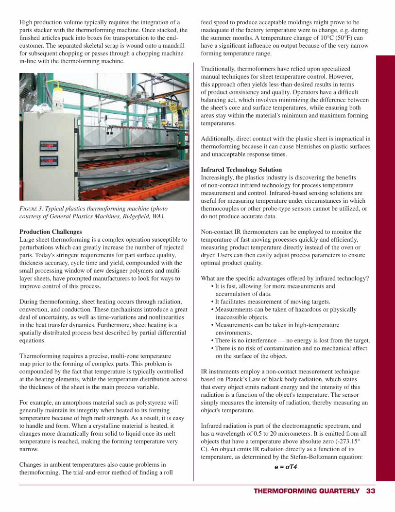
Thermoforming QuarTerly 33
High production volume typically requires the integration of a parts stacker with the thermoforming machine. Once stacked, the finished articles pack into boxes for transportation to the end-customer. The separated skeletal scrap is wound onto a mandrill for subsequent chopping or passes through a chopping machine in-line with the thermoforming machine.
Figure 3. Typical plastics thermoforming machine (photo courtesy of General Plastics Machines, Ridgefield, WA).
Production ChallengesLarge sheet thermoforming is a complex operation susceptible to perturbations which can greatly increase the number of rejected parts. Today's stringent requirements for part surface quality, thickness accuracy, cycle time and yield, compounded with the small processing window of new designer polymers and multi-layer sheets, have prompted manufacturers to look for ways to improve control of this process.
During thermoforming, sheet heating occurs through radiation, convection, and conduction. These mechanisms introduce a great deal of uncertainty, as well as time-variations and nonlinearities in the heat transfer dynamics. Furthermore, sheet heating is a spatially distributed process best described by partial differential equations.
Thermoforming requires a precise, multi-zone temperature map prior to the forming of complex parts. This problem is compounded by the fact that temperature is typically controlled at the heating elements, while the temperature distribution across the thickness of the sheet is the main process variable.
For example, an amorphous material such as polystyrene will generally maintain its integrity when heated to its forming temperature because of high melt strength. As a result, it is easy to handle and form. When a crystalline material is heated, it changes more dramatically from solid to liquid once its melt temperature is reached, making the forming temperature very narrow.
Changes in ambient temperatures also cause problems in thermoforming. The trial-and-error method of finding a roll
feed speed to produce acceptable moldings might prove to be inadequate if the factory temperature were to change, e.g. during the summer months. A temperature change of 10°C (50°F) can have a significant influence on output because of the very narrow forming temperature range.
Traditionally, thermoformers have relied upon specialized manual techniques for sheet temperature control. However, this approach often yields less-than-desired results in terms of product consistency and quality. Operators have a difficult balancing act, which involves minimizing the difference between the sheet's core and surface temperatures, while ensuring both areas stay within the material's minimum and maximum forming temperatures.
Additionally, direct contact with the plastic sheet is impractical in thermoforming because it can cause blemishes on plastic surfaces and unacceptable response times.
Infrared Technology SolutionIncreasingly, the plastics industry is discovering the benefits of non-contact infrared technology for process temperature measurement and control. Infrared-based sensing solutions are useful for measuring temperature under circumstances in which thermocouples or other probe-type sensors cannot be utilized, or do not produce accurate data.
Non-contact IR thermometers can be employed to monitor the temperature of fast moving processes quickly and efficiently, measuring product temperature directly instead of the oven or dryer. Users can then easily adjust process parameters to ensure optimal product quality.
What are the specific advantages offered by infrared technology?• It is fast, allowing for more measurements and
accumulation of data.• It facilitates measurement of moving targets.• Measurements can be taken of hazardous or physically
inaccessible objects.• Measurements can be taken in high-temperature
environments.• There is no interference — no energy is lost from the target.• There is no risk of contamination and no mechanical effect
on the surface of the object.
IR instruments employ a non-contact measurement technique based on Planck’s Law of black body radiation, which states that every object emits radiant energy and the intensity of this radiation is a function of the object's temperature. The sensor simply measures the intensity of radiation, thereby measuring an object's temperature.
Infrared radiation is part of the electromagnetic spectrum, and has a wavelength of 0.5 to 20 micrometers. It is emitted from all objects that have a temperature above absolute zero (-273.15° C). An object emits IR radiation directly as a function of its temperature, as determined by the Stefan-Boltzmann equation:
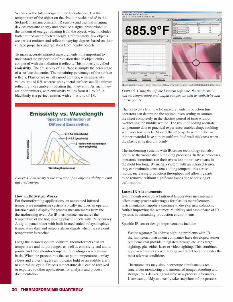
34 Thermoforming QuarTerly
Where e is the total energy emitted by radiation, T is the temperature of the object on the absolute scale, and o is the Stefan-Boltzmann constant. IR sensors and thermal imaging devices measure energy and produce a signal proportional to the amount of energy radiating from the object, which includes both emitted and reflected energy. Unfortunately, few objects are perfect emitters and reflect to varying degrees based on their surface properties and radiation from nearby objects.
To make accurate infrared measurements, it is important to understand the proportion of radiation that an object emits compared with the radiation it reflects. This property is called emissivity. The emissivity of a surface is simply the percentage of a surface that emits. The remaining percentage of the surface reflects. Plastics are usually good emitters, with emissivity values around 0.9, whereas shiny metal surfaces act like mirrors reflecting more ambient radiation than they emit. As such, they are poor emitters, with emissivity values from 0.1 to 0.3. A blackbody is a perfect emitter, with emissivity of 1.0.
Figure 4. Emissivity is the measure of an object's ability to emit infrared energy.
How an IR System WorksFor thermoforming applications, an automated infrared temperature monitoring system typically includes an operator interface and a display for process measurements from the thermoforming oven. An IR thermometer measures the temperature of the hot, moving plastic sheets with 1% accuracy. A digital panel meter with built-in mechanical relays displays temperature data and outputs alarm signals when the set point temperature is reached.
Using the infrared system software, thermoformers can set temperature and output ranges, as well as emissivity and alarm points, and then monitor temperature readings on a real-time basis. When the process hits the set point temperature, a relay closes and either triggers an indicator light or an audible alarm to control the cycle. Process temperature data can be archived or exported to other applications for analysis and process documentation.
Figure 5. Using the infrared system software, thermoformers can set temperature and output ranges, as well as emissivity and alarm points.
Thanks to data from the IR measurements, production line operators can determine the optimal oven setting to saturate the sheet completely in the shortest period of time without overheating the middle section. The result of adding accurate temperature data to practical experience enables drape molding with very few rejects. More difficult projects with thicker or thinner material have a more uniform final wall thickness when the plastic is heated uniformly.
Thermoforming systems with IR sensor technology can also optimize thermoplastic de-molding processes. In these processes, operators sometimes run their ovens too hot or leave parts in the mold too long. By using a system with an infrared sensor, they can maintain consistent cooling temperatures across molds, increasing production throughput and allowing parts to be removed without significant losses due to sticking or deformation.
Latest IR AdvancementsEven though non-contact infrared temperature measurement offers many proven advantages for plastics manufacturers, instrumentation suppliers continue to develop new solutions, further improving the accuracy, reliability and ease-of-use of IR systems in demanding production environments.
Specific IR sensor design improvements include:
Easier sighting: To address sighting problems with IR thermometers, instrument companies have developed sensor platforms that provide integrated through-the-lens target sighting, plus either laser or video sighting. This combined approach ensures correct aiming and target location under the most adverse conditions.
Thermometers may also incorporate simultaneous real-time video monitoring and automated image recording and storage, thus delivering valuable new process information. Users can quickly and easily take snapshots of the process
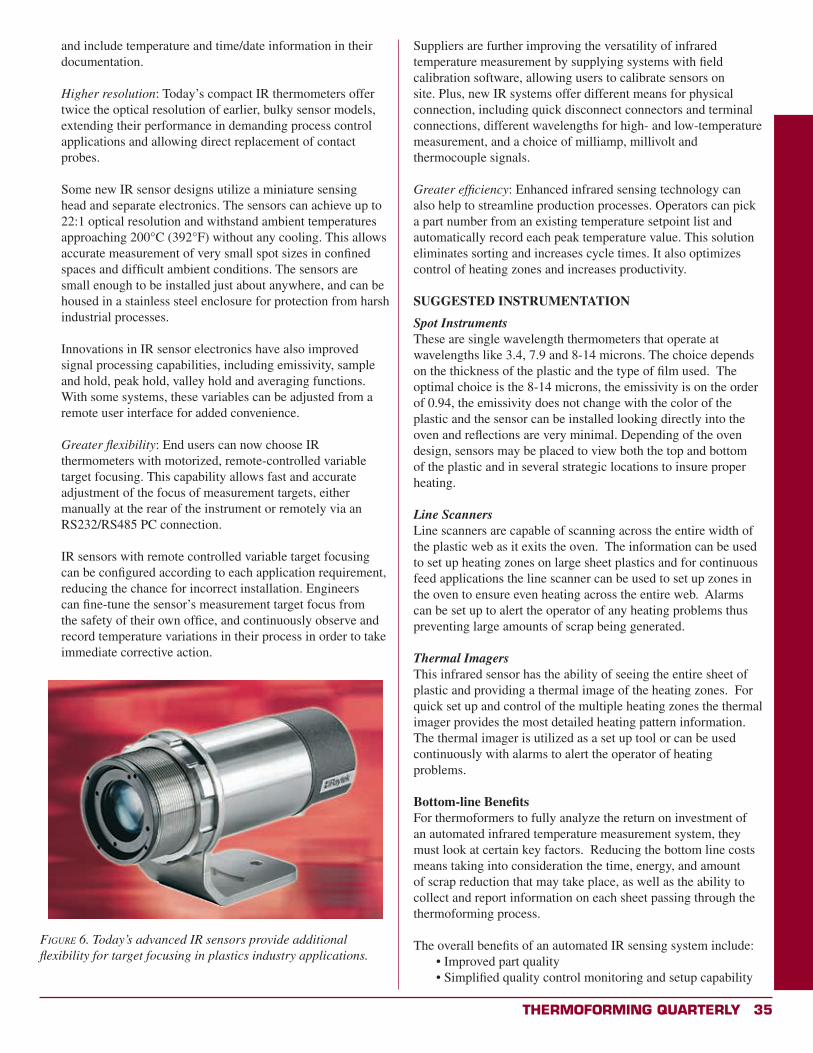
Thermoforming QuarTerly 35
and include temperature and time/date information in their documentation.
Higher resolution: Today’s compact IR thermometers offer twice the optical resolution of earlier, bulky sensor models, extending their performance in demanding process control applications and allowing direct replacement of contact probes.
Some new IR sensor designs utilize a miniature sensing head and separate electronics. The sensors can achieve up to 22:1 optical resolution and withstand ambient temperatures approaching 200°C (392°F) without any cooling. This allows accurate measurement of very small spot sizes in confined spaces and difficult ambient conditions. The sensors are small enough to be installed just about anywhere, and can be housed in a stainless steel enclosure for protection from harsh industrial processes.
Innovations in IR sensor electronics have also improved signal processing capabilities, including emissivity, sample and hold, peak hold, valley hold and averaging functions. With some systems, these variables can be adjusted from a remote user interface for added convenience.
Greater flexibility: End users can now choose IR thermometers with motorized, remote-controlled variable target focusing. This capability allows fast and accurate adjustment of the focus of measurement targets, either manually at the rear of the instrument or remotely via an RS232/RS485 PC connection.
IR sensors with remote controlled variable target focusing can be configured according to each application requirement, reducing the chance for incorrect installation. Engineers can fine-tune the sensor’s measurement target focus from the safety of their own office, and continuously observe and record temperature variations in their process in order to take immediate corrective action.
Figure 6. Today’s advanced IR sensors provide additional flexibility for target focusing in plastics industry applications.
Suppliers are further improving the versatility of infrared temperature measurement by supplying systems with field calibration software, allowing users to calibrate sensors on site. Plus, new IR systems offer different means for physical connection, including quick disconnect connectors and terminal connections, different wavelengths for high- and low-temperature measurement, and a choice of milliamp, millivolt and thermocouple signals.
Greater efficiency: Enhanced infrared sensing technology can also help to streamline production processes. Operators can pick a part number from an existing temperature setpoint list and automatically record each peak temperature value. This solution eliminates sorting and increases cycle times. It also optimizes control of heating zones and increases productivity.
SUGGESTED INSTRUMENTATION
Spot InstrumentsThese are single wavelength thermometers that operate at wavelengths like 3.4, 7.9 and 8-14 microns. The choice depends on the thickness of the plastic and the type of film used. The optimal choice is the 8-14 microns, the emissivity is on the order of 0.94, the emissivity does not change with the color of the plastic and the sensor can be installed looking directly into the oven and reflections are very minimal. Depending of the oven design, sensors may be placed to view both the top and bottom of the plastic and in several strategic locations to insure proper heating.
Line ScannersLine scanners are capable of scanning across the entire width of the plastic web as it exits the oven. The information can be used to set up heating zones on large sheet plastics and for continuous feed applications the line scanner can be used to set up zones in the oven to ensure even heating across the entire web. Alarms can be set up to alert the operator of any heating problems thus preventing large amounts of scrap being generated.
Thermal ImagersThis infrared sensor has the ability of seeing the entire sheet of plastic and providing a thermal image of the heating zones. For quick set up and control of the multiple heating zones the thermal imager provides the most detailed heating pattern information. The thermal imager is utilized as a set up tool or can be used continuously with alarms to alert the operator of heating problems.
Bottom-line BenefitsFor thermoformers to fully analyze the return on investment of an automated infrared temperature measurement system, they must look at certain key factors. Reducing the bottom line costs means taking into consideration the time, energy, and amount of scrap reduction that may take place, as well as the ability to collect and report information on each sheet passing through the thermoforming process.
The overall benefits of an automated IR sensing system include:• Improved part quality• Simplified quality control monitoring and setup capability

36 Thermoforming QuarTerly
• Identification of over-heated or under-heated sheets before making defective (off-spec) parts
• Ability to thermoform more difficult parts• Ability to archive and provide customers
with a thermal image of every part manufactured for quality documentation and ISO compliance
• Increased throughput by reducing part residence time in the heating section
• Higher yields by significantly cutting down equipment set-up and qualification times
• Early detection of heater problems affecting process efficiency and energy consumption
ConclusionNon-contact infrared temperature measurement is not a new technology, but recent innovations have reduced costs, increased reliability, and enabled smaller units of measurement. Thermoformers utilizing IR technology see an improvement in production, and they do not have as much scrap. They also make better quality parts because they get uniform thickness coming out of their thermoforming machine.
ReferencesJ. Lappin and P. Martin, “Sheet Temperature Measurement In Thermoforming,” Plastics Engineering, July 1996.
B. Elder, “Just One Word: Plastics,” InTech, June 2007. x
©2013 PolyOne Corporation
It can. PolyOne’s unmatched portfolio of innovative solutions can help you find just the right answer for your most pressing needs. Whether it’s to increase productivity, lower scrap rates, reach new markets, or grow through unique innovations, we can help. Our customer-focused approach and world-class capabilities in polymer formulation, performance additives and colorants, sheet and rollstock, and packaging solutions can help you overcome your greatest hurdles and grow your bottom line. For answers to the biggest questions facing your business visit us at Booth 525 at the SPE Thermoforming Conference in Atlanta or online at http://www.DSS.Polyone.com. Make it possible.
A single supplier could help you find just the
right solution for your toughest challenges?
R E D U C E ! R E U S E ! R E C Y C L E !
Have an idea for an article?
Submission Guidelines• We are a technical journal. We strive for objective, technical articles that help advance our readers’ understanding of thermoforming (process, tooling, machinery, ancillary services); in other words, no commercials.
• Article length:1,000 - 2,000 words. Look to past articles for guidance.• Format: .doc or .docxArtwork: hi-res images are encouraged (300 dpi) with appropriate credits.
Send all submissions to Conor Carlin, [email protected]

Thermoforming QuarTerly 37
38 Thermoforming QuarTerly
ThermoformingQuarterly® Thermoforming and Sustainability
PET Thermoform Recycling, One Year LaterAn update as provided by the National Association for PET Container Resources (NAPCOR)
By Kate Eagles, NAPCOR, with NAPCOR staff
BackgroundWhen NAPCOR broadened its membership in 2007 to include PET sheet and thermoform manufacturers, the PET packaging trade organization set its sights on an ambitious long-term objective: to overcome the barriers to the domestic recycling and reclamation of PET thermoformed packaging without causing harm to existing PET bottle reclamation assets.
As detailed in the previous Thermoforming Quarterly article, “PET Thermoform Recycling: Its Time Has Come” (Q1 2012), NAPCOR enlisted the support of its members and other stakeholders to work toward this goal, facilitating lab testing and practical trials with intermediate processors and PET reclaimers. The primary barriers to successful thermoform recycling and reclamation were identified as follows:
1) “Look alike” non-PET thermoformed packaging (e.g., PS, PLA, PVC, PETG) that is difficult to visually distinguish from PET. This is mainly a concern for facilities that are sorting material manually, but can even be a challenge for autosort equipment due to mechanical issues (see 4 below).
2) The labels / adhesives / inks commonly used on thermoformed packaging are usually pressure-sensitive paper with more aggressive adhesive than those used on bottles, which if not completely removed in the PET reclamation process, can adversely affect the quality of the recycled PET material produced.
3) Relatively high levels of fluorescence were observed in some PET packaging samples. Fluorescent material is not acceptable to carpet manufacturers that use recycled PET feedstock; it can cause inconsistent dye uptake and streaking.
4) Mechanical issues pertaining to thermoformed packaging, including varied package shapes, sizes and weights, leads to more unpredictability as to how this material will travel through a materials recovery facility (MRF), or a reclamation operation, versus more uniform PET bottles and containers. Thermoform material can clump, jamming transition points; conversely, it can flutter going through autosort units, reducing sorting accuracy.
Have these barriers been successfully overcome? Do we now have domestic recycling of PET thermoforms? Somewhat, and yes, but there is more work to be done, and detail on the status of the barriers is provided below. In terms of domestic recycling, there are now municipalities in both Canada and the United States that are successfully collecting, sorting, and
selling their PET thermoforms. This material is being processed by reclaimers and sold into the same end-use markets as are PET bottles, mainly fiber (carpet and other), and food and non-food packaging. PET thermoforms are currently marketed in two ways: 1) mixed in with bottle bales at a not-to-exceed percentage agreed with the individual reclaimer or buyer, and 2) as dedicated, all-PET-thermoform bales. In its 2011 PET recycling rate report, NAPCOR cited the total volume of postconsumer PET thermoforms recycled at 45 million pounds. For 2012, that number had increased slightly to 47.8 million pounds.1
The city of Toronto added PET thermoforms to its Blue Bin program in the summer of 2012, following the cities of Ottawa and Calgary. A report from the Canadian Plastics Industry Association reports that 89% of Canada’s population has access to non-bottle PET recycling.2 These municipal program expansions were driven in part by the leadership efforts of several large Canadian retailers, beginning in 2010. Initiated by Loblaw’s and Walmart Canada, they were subsequently supported by Sobey’s, Metro and Safeway Canada through their trade association, now the Retail Council of Canada. These retailers proactively addressed the NAPCOR-identified obstacles to the recycling of their in-store thermoformed packaging, and continue to do so. More detail on this work is provided in the “Status of Barriers” section below. It is also the subject of a packaging stewardship case study.3
NAPCOR and SPI awarded $100,000 in grant monies in early 2012 to support model programs for PET thermoform recycling. Plastic Ingenuity, Solo Cup and Placon contributed additional funds, allowing for three grantees: the Division of Solid Waste Services, Department of Environmental Protection, Montgomery County, Maryland; Firstar Fiber, Omaha, Nebraska; and the Pennsylvania Markets Center, for programs in Lebanon and Elk counties. All three programs are over a year into their two-year grant cycle, and all are successfully collecting, sorting and marketing PET thermoforms.
“Our PET thermoform recycling program is working really well for us,” says Tom Kusterer, Program Manager for the Montgomery County, Maryland, program, “and we are very happy to be able to find domestic markets and a higher value for our PET material.” Through their program to date, Montgomery County has marketed over 150 tons of PET thermoforms. “We put some thought into this program because we are manually sorting, and there are look-alike thermoforms in the stream. We pull our PET thermoforms using a manual “positive” sort with
Thermoforming QuarTerly 39
PET thermoform-trained personnel working the line. NAPCOR provided us with basic tips on how to spot PET versus non-PET, and we’ve built on this, even doing a simple in-house video in English and Spanish. We pull PET thermoforms during a “second sort” so fiber, metals, and PET and HDPE bottles have been already removed, greatly reducing the volume of material on the line. This is working well for us.”4
The other two grantees are also sorting manually, Firstar Fiber at their MRF, pulling mainly from curbside material and mixing thermoforms in with PET bottles at an agreed percentage, and Pennsylvania, through drop-off facilities in Lebanon and Elk counties, Lebanon baling dedicated PET thermoform bales, and Elk mixing thermoforms in with their PET bottles.
Status of Recycling Barriers & Partnerships to Address Them NAPCOR is encouraged by the success of Canadian and US programs, but the work to comprehensively overcome the barriers listed above is still in progress. With a chronically undersupplied postconsumer PET bale market, supply is certainly a driver for PET reclaimers when it comes to PET thermoform recycling, and yet some remain cautious. The advent of single-stream curbside recycling makes recycling easier for consumers, but is not necessarily conducive to PET bale quality. There are certainly exceptions, but generally speaking, curbside PET bale quality continues to decline, meaning increased yield loss for reclaimers from non-PET material.
Look-Alike PackagingMRFs serving communities that want to market their PET thermoforms domestically will potentially exacerbate these bale quality issues unless they use stringent best practice sorting techniques to avoid inclusion of look-alike non-PET thermoforms. This can be achieved using autosort technology or through careful manual sorting, as evidenced by Montgomery County’s success, but it still remains a concern.
“It’s not the thermoforms that are causing bale quality and yield loss issues for us,” reports one NAPCOR reclaimer member, “but the non-PET portion in the bales. Not all thermoforms are PET, and I encourage our customers not to sacrifice their bale quality in order to add PET thermoforms, but to first implement ‘best practice’ sorting to retain bale quality and best market value.”
If more of the recycled stream is made up of PET, look-alike packages become less prevalent and thus less of an issue. This was the conclusion of the Canadian grocers mentioned above. All five have converted their in-store packaging to PET, or are in the process of doing so, in an effort to build critical mass for PET and reduce look-alikes. This commitment and leadership has demonstrably furthered the PET thermoform recycling effort in Canada. While influencing the critical mass for PET is arguably more challenging in the United States, the specification of PET (#1) by package designers, retailers and brand mangers will speed progress toward successful, widespread domestic recycling of PET thermoform packaging. PET’s recyclability, barrier properties, clarity, ability to incorporate high levels of recycled content, energy and GHG reductions (through use of recycled PET) provide additional reasons for choosing PET.5
Labels / Adhesives / InksAs previously reported, the pressure-sensitive paper labels and adhesives commonly used on thermoform packaging tend to be more difficult to remove in the current PET reclamation process, requiring more residence time, more caustic, higher wash temperatures, or all three. Again spear-headed by the Canadian grocers’ efforts to recycle more of their in-store packaging, NAPCOR and the Association of Postconsumer Plastic Recyclers developed Critical Guidance for Innovations protocol for evaluating recycling compatible labels and adhesives. Labels that conform to these protocols are published on the APR web site.6
Currently, NAPCOR finds that despite the ongoing Canadian retailer push for their suppliers to use only conforming labels, the switch is happening slowly. The are various factors that play into this, including how inks fit in to the label / adhesive mix in terms of recycling compatibility; label material cost and performance trade-offs; and whether the APR tests might evolve to efficiently accommodate the array of label / adhesive / ink combinations. The ultimate goal is to have more conforming label options available. Over the last few months, NAPCOR staff and NAPCOR member Avery Dennison have worked with the Tag & Label Manufacturers Institute (TLMI) to better understand these issues so that they can be addressed, recently forming a work group to include the APR, a label converter, ink and adhesive suppliers, and retail grocery and consumer brand company representatives. The group has collectively agreed to some label / adhesive / ink trials, and planning for these is currently underway.
FluorescenceMarked use of fluorescence was seen in some of the PET thermoform samples originally evaluated in 2010. The use of fluorescence was most prevalent in specific produce containers. WalMart Canada took the initiative to educate its suppliers about why this is problematic for the recycled PET made from these packages, and to NAPCOR’s knowledge, fluorescence use in packaging is not an issue at this time.
Mechanical Issues The differences in the way thermoformed material runs through reclamation plants, versus that of more uniform PET bottles, is not an insignificant issue, but is one that falls into the domain of the individual PET reclaimers. Many have made changes and retrofits to their plants over the last year, which will enable thermoformed material to more efficiently move through their plants, or are in the process of doing so. Facilities such as Placon’s Ecostar (Madison, WI) and Perpetual Recycling (Richmond, IN) were designed to be able to accommodate PET thermoformed material. For MRFs that wish to market all-PET-thermoform bales, communication with their PET buyer(s) is again important as the baler platen pressure should be modified from that of PET bottle bales in order to prevent excessive bale density, resulting in “bricks” of material that don’t readily come apart for sorting and processing once bales are broken.
In summary, while some of the obstacles identified over a year ago continue to be addressed, PET thermoform recycling in the USA and Canada is gradually increasing. NAPCOR encourages
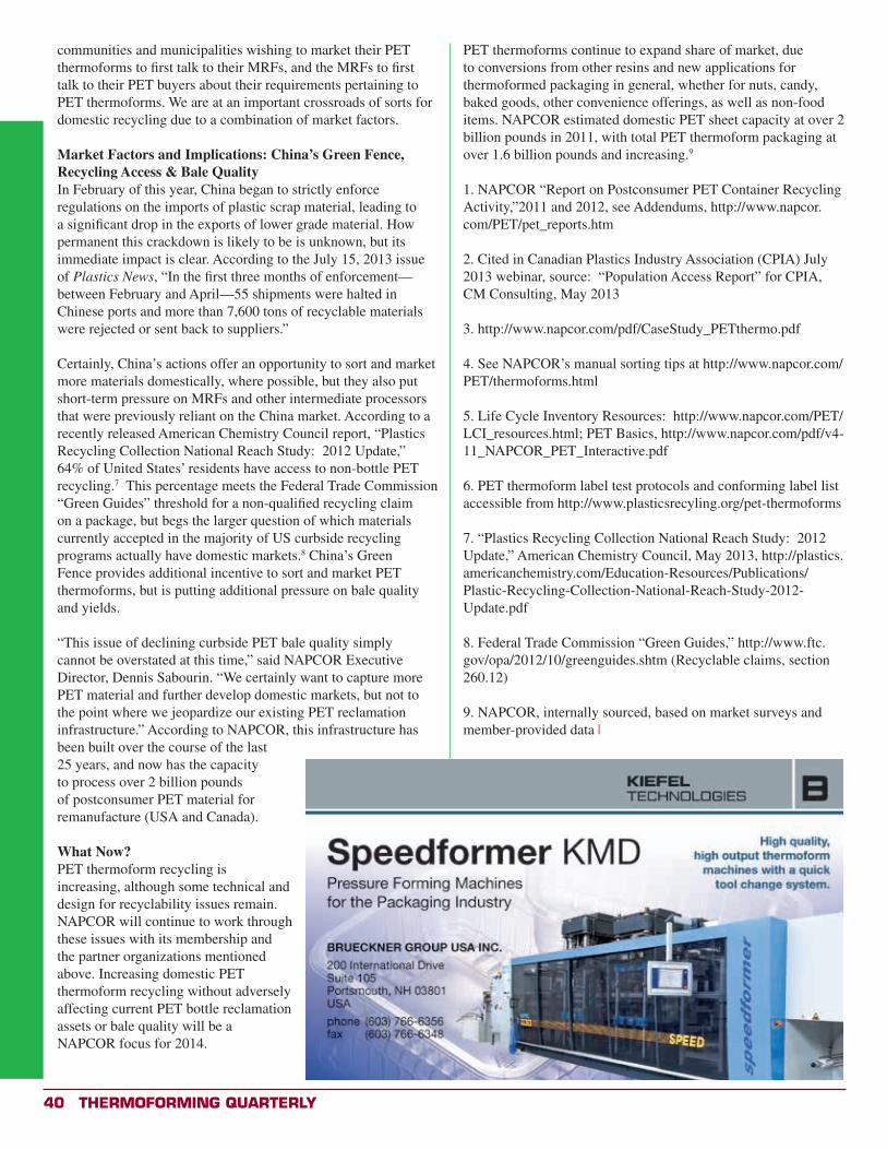
40 Thermoforming QuarTerly
communities and municipalities wishing to market their PET thermoforms to first talk to their MRFs, and the MRFs to first talk to their PET buyers about their requirements pertaining to PET thermoforms. We are at an important crossroads of sorts for domestic recycling due to a combination of market factors.
Market Factors and Implications: China’s Green Fence, Recycling Access & Bale QualityIn February of this year, China began to strictly enforce regulations on the imports of plastic scrap material, leading to a significant drop in the exports of lower grade material. How permanent this crackdown is likely to be is unknown, but its immediate impact is clear. According to the July 15, 2013 issue of Plastics News, “In the first three months of enforcement—between February and April—55 shipments were halted in Chinese ports and more than 7,600 tons of recyclable materials were rejected or sent back to suppliers.”
Certainly, China’s actions offer an opportunity to sort and market more materials domestically, where possible, but they also put short-term pressure on MRFs and other intermediate processors that were previously reliant on the China market. According to a recently released American Chemistry Council report, “Plastics Recycling Collection National Reach Study: 2012 Update,” 64% of United States’ residents have access to non-bottle PET recycling.7 This percentage meets the Federal Trade Commission “Green Guides” threshold for a non-qualified recycling claim on a package, but begs the larger question of which materials currently accepted in the majority of US curbside recycling programs actually have domestic markets.8 China’s Green Fence provides additional incentive to sort and market PET thermoforms, but is putting additional pressure on bale quality and yields.
“This issue of declining curbside PET bale quality simply cannot be overstated at this time,” said NAPCOR Executive Director, Dennis Sabourin. “We certainly want to capture more PET material and further develop domestic markets, but not to the point where we jeopardize our existing PET reclamation infrastructure.” According to NAPCOR, this infrastructure has been built over the course of the last 25 years, and now has the capacity to process over 2 billion pounds of postconsumer PET material for remanufacture (USA and Canada).
What Now? PET thermoform recycling is increasing, although some technical and design for recyclability issues remain. NAPCOR will continue to work through these issues with its membership and the partner organizations mentioned above. Increasing domestic PET thermoform recycling without adversely affecting current PET bottle reclamation assets or bale quality will be a NAPCOR focus for 2014.
PET thermoforms continue to expand share of market, due to conversions from other resins and new applications for thermoformed packaging in general, whether for nuts, candy, baked goods, other convenience offerings, as well as non-food items. NAPCOR estimated domestic PET sheet capacity at over 2 billion pounds in 2011, with total PET thermoform packaging at over 1.6 billion pounds and increasing.9
1. NAPCOR “Report on Postconsumer PET Container Recycling Activity,”2011 and 2012, see Addendums, http://www.napcor.com/PET/pet_reports.htm
2. Cited in Canadian Plastics Industry Association (CPIA) July 2013 webinar, source: “Population Access Report” for CPIA, CM Consulting, May 2013
3. http://www.napcor.com/pdf/CaseStudy_PETthermo.pdf
4. See NAPCOR’s manual sorting tips at http://www.napcor.com/PET/thermoforms.html
5. Life Cycle Inventory Resources: http://www.napcor.com/PET/LCI_resources.html; PET Basics, http://www.napcor.com/pdf/v4-11_NAPCOR_PET_Interactive.pdf
6. PET thermoform label test protocols and conforming label list accessible from http://www.plasticsrecyling.org/pet-thermoforms
7. “Plastics Recycling Collection National Reach Study: 2012 Update,” American Chemistry Council, May 2013, http://plastics.americanchemistry.com/Education-Resources/Publications/Plastic-Recycling-Collection-National-Reach-Study-2012-Update.pdf
8. Federal Trade Commission “Green Guides,” http://www.ftc.gov/opa/2012/10/greenguides.shtm (Recyclable claims, section 260.12)
9. NAPCOR, internally sourced, based on market surveys and member-provided data x
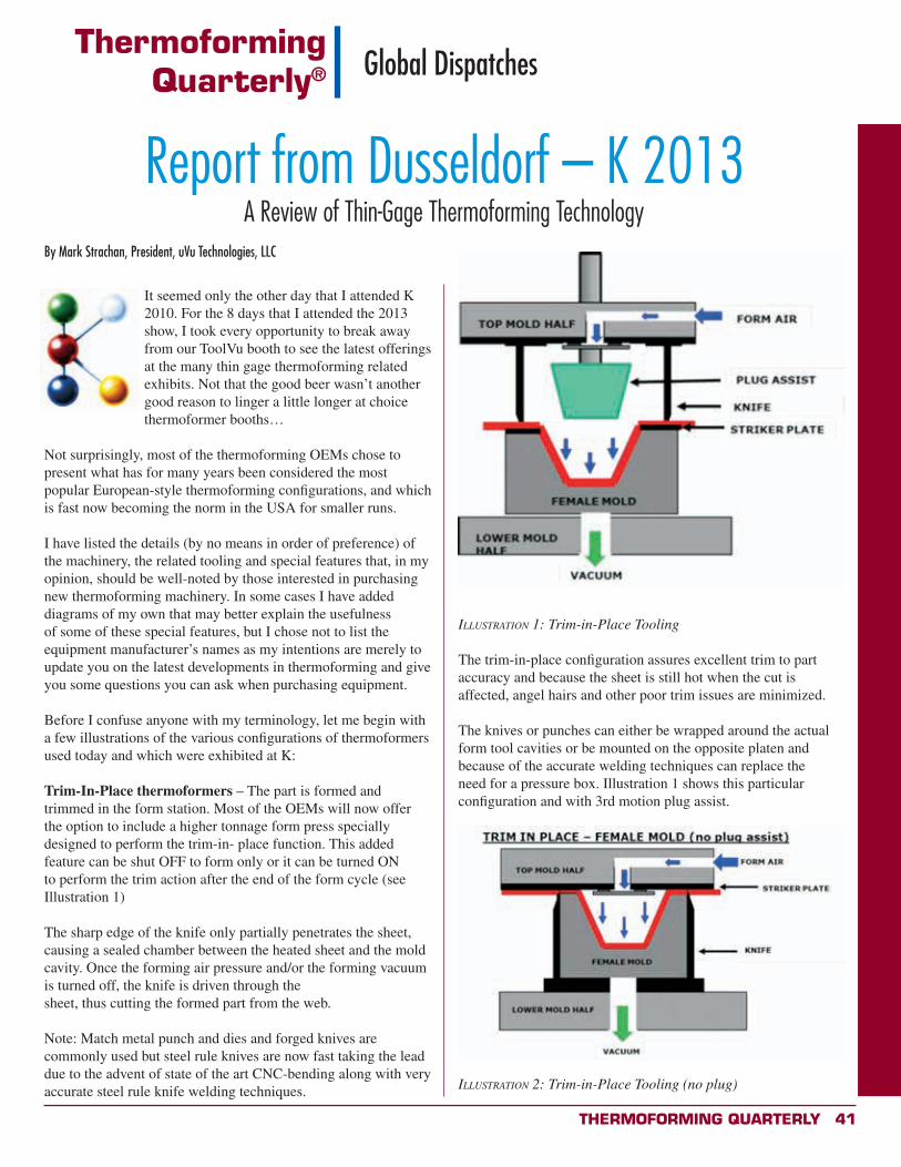
Thermoforming QuarTerly 41
It seemed only the other day that I attended K 2010. For the 8 days that I attended the 2013 show, I took every opportunity to break away from our ToolVu booth to see the latest offerings at the many thin gage thermoforming related exhibits. Not that the good beer wasn’t another good reason to linger a little longer at choice thermoformer booths…
Not surprisingly, most of the thermoforming OEMs chose to present what has for many years been considered the most popular European-style thermoforming configurations, and which is fast now becoming the norm in the USA for smaller runs.
I have listed the details (by no means in order of preference) of the machinery, the related tooling and special features that, in my opinion, should be well-noted by those interested in purchasing new thermoforming machinery. In some cases I have added diagrams of my own that may better explain the usefulness of some of these special features, but I chose not to list the equipment manufacturer’s names as my intentions are merely to update you on the latest developments in thermoforming and give you some questions you can ask when purchasing equipment.
Before I confuse anyone with my terminology, let me begin with a few illustrations of the various configurations of thermoformers used today and which were exhibited at K:
Trim-In-Place thermoformers – The part is formed and trimmed in the form station. Most of the OEMs will now offer the option to include a higher tonnage form press specially designed to perform the trim-in- place function. This added feature can be shut OFF to form only or it can be turned ON to perform the trim action after the end of the form cycle (see Illustration 1)
The sharp edge of the knife only partially penetrates the sheet, causing a sealed chamber between the heated sheet and the mold cavity. Once the forming air pressure and/or the forming vacuum is turned off, the knife is driven through the sheet, thus cutting the formed part from the web.
Note: Match metal punch and dies and forged knives are commonly used but steel rule knives are now fast taking the lead due to the advent of state of the art CNC-bending along with very accurate steel rule knife welding techniques.
illusTraTion 1: Trim-in-Place Tooling
The trim-in-place configuration assures excellent trim to part accuracy and because the sheet is still hot when the cut is affected, angel hairs and other poor trim issues are minimized.
The knives or punches can either be wrapped around the actual form tool cavities or be mounted on the opposite platen and because of the accurate welding techniques can replace the need for a pressure box. Illustration 1 shows this particular configuration and with 3rd motion plug assist.
illusTraTion 2: Trim-in-Place Tooling (no plug)
ThermoformingQuarterly® Global Dispatches
Report from Dusseldorf – K 2013A Review of Thin-Gage Thermoforming Technology
By Mark Strachan, President, uVu Technologies, LLC
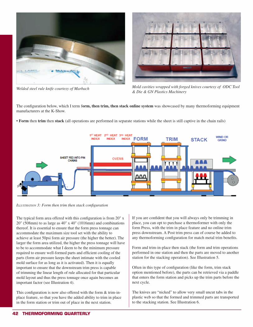
42 Thermoforming QuarTerly
The configuration below, which I term form, then trim, then stack online system was showcased by many thermoforming equipment manufacturers at the K-Show.
• Form then trim then stack (all operations are performed in separate stations while the sheet is still captive in the chain rails)
illusTraTion 3: Form then trim then stack configuration
The typical form area offered with this configuration is from 20" x 20" (508mm) to as large as 40" x 40" (1016mm) and combinations thereof. It is essential to ensure that the form press tonnage can accommodate the maximum size tool set with the ability to achieve at least 50psi form air pressure (the higher the better). The larger the form area utilized, the higher the press tonnage will have to be to accommodate what I deem to be the minimum pressure required to ensure well-formed parts and efficient cooling of the parts (form air pressure keeps the sheet intimate with the cooled mold surface for as long as it is activated). Then it is equally important to ensure that the downstream trim press is capable of trimming the linear length of rule allocated for that particular mold layout and thus the press tonnage once again becomes an important factor (see Illustration 4).
This configuration is now also offered with the form & trim-in-place feature, so that you have the added ability to trim in place in the form station or trim out of place in the next station.
If you are confident that you will always only be trimming in place, you can opt to purchase a thermoformer with only the form Press, with the trim in place feature and no online trim press downstream. A Post trim press can of course be added to any thermoforming configuration for match metal trim benefits.
Form and trim-in-place then stack (the form and trim operations performed in one station and then the parts are moved to another station for the stacking operation). See Illustration 5.
Often in this type of configuration (like the form, trim stack option mentioned before), the parts can be retrieved via a paddle that enters the form station and picks up the trim parts before the next cycle.
The knives are “nicked” to allow very small uncut tabs in the plastic web so that the formed and trimmed parts are transported to the stacking station. See Illustration 6.
Mold cavities wrapped with forged knives courtesy of ODC Tool & Die & GN Plastics Machinery
Welded steel rule knife courtesy of Marbach
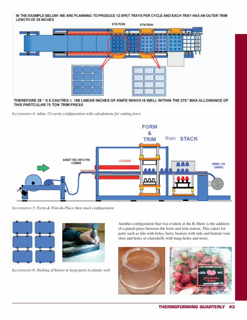
Thermoforming QuarTerly 43
Another configuration that was evident at the K-Show is the addition of a punch press between the form and trim station. This caters for parts such as lids with holes, berry baskets with side and bottom vent slots and holes or clamshells with hang-holes and more.
illusTraTion 4: inline 12-cavity configuration with calculations for cutting force
illusTraTion 5: Form & Trim-In-Place then stack configuration
illusTraTion 6: Nicking of knives to keep parts in plastic web
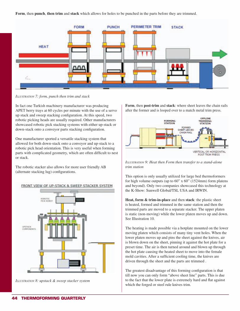
44 Thermoforming QuarTerly
illusTraTion 7: form, punch then trim and stack
In fact one Turkish machinery manufacturer was producing APET berry trays at 60 cycles per minute with the use of a servo up stack and sweep stacking configuration. At this speed, two robotic picking heads are usually required. Other manufacturers showcased robotic pick stacking systems with either up-stack or down-stack onto a conveyor parts stacking configuration.
One manufacturer sported a versatile stacking system that allowed for both down-stack onto a conveyor and up-stack to a robotic pick head orientation. This is very useful when forming parts with complicated geometry, which are often difficult to nest or stack.
The robotic stacker also allows for more user friendly AB (alternate stacking lug) configurations.
Form, then punch, then trim and stack which allows for holes to be punched in the parts before they are trimmed.
illusTraTion 8: upstack & sweep stacker system
Form, then post-trim and stack: where sheet leaves the chain rails after the former and is looped over to a match metal trim press.
illusTraTion 9: Heat then Form then transfer to a stand-alone trim station
This option is only usually utilized for large bed thermoformers for high volume outputs (up to 60” x 60” (1524mm) form platens and beyond). Only two companies showcased this technology at the K-Show: Sunwell Global/TSL USA and IRWIN.
Heat, form & trim-in-place and then stack: the plastic sheet is heated, formed and trimmed in the same station and then the trimmed parts are moved to a separate stacker. The upper platen is static (non-moving) while the lower platen moves up and down. See Illustration 10.
The heating is made possible via a hotplate mounted on the lower moving platen which consists of many tiny vent holes. When the lower platen moves up and pins the sheet against the knives, air is blown down on the sheet, pinning it against the hot plate for a preset time. The air is then turned around and blown up through the hot plate causing the heated sheet to move into the female mold cavities. After a sufficient cooling time, the knives are driven through the sheet and the parts are trimmed .
The greatest disadvantage of this forming configuration is that till now you can only form “above sheet line” parts. This is due to the fact that the lower plate is extremely hard and flat against which the forged or steel rule knives trim.
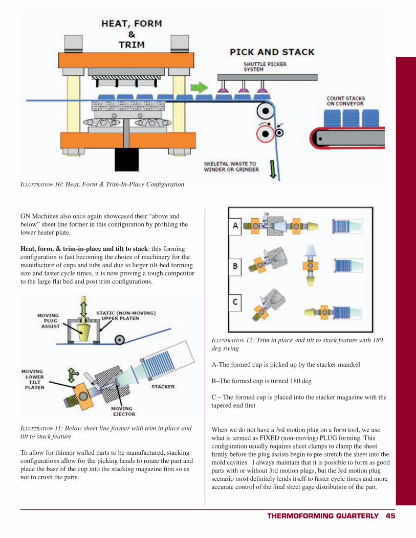
Thermoforming QuarTerly 45
GN Machines also once again showcased their “above and below” sheet line former in this configuration by profiling the lower heater plate.
Heat, form, & trim-in-place and tilt to stack: this forming configuration is fast becoming the choice of machinery for the manufacture of cups and tubs and due to larger tilt-bed forming size and faster cycle times, it is now proving a tough competitor to the large flat bed and post trim configurations.
illusTraTion 11: Below sheet line former with trim in place and tilt to stack feature
To allow for thinner walled parts to be manufactured, stacking configurations allow for the picking heads to rotate the part and place the base of the cup into the stacking magazine first so as not to crush the parts.
illusTraTion 10: Heat, Form & Trim-In-Place Configuration
illusTraTion 12: Trim in place and tilt to stack feature with 180 deg swing
A-The formed cup is picked up by the stacker mandrel
B–The formed cup is turned 180 deg
C – The formed cup is placed into the stacker magazine with the tapered end first
When we do not have a 3rd motion plug on a form tool, we use what is termed as FIXED (non-moving) PLUG forming. This configuration usually requires sheet clamps to clamp the sheet firmly before the plug assists begin to pre-stretch the sheet into the mold cavities. I always maintain that it is possible to form as good parts with or without 3rd motion plugs, but the 3rd motion plug scenario most definitely lends itself to faster cycle times and more accurate control of the final sheet gage distribution of the part.
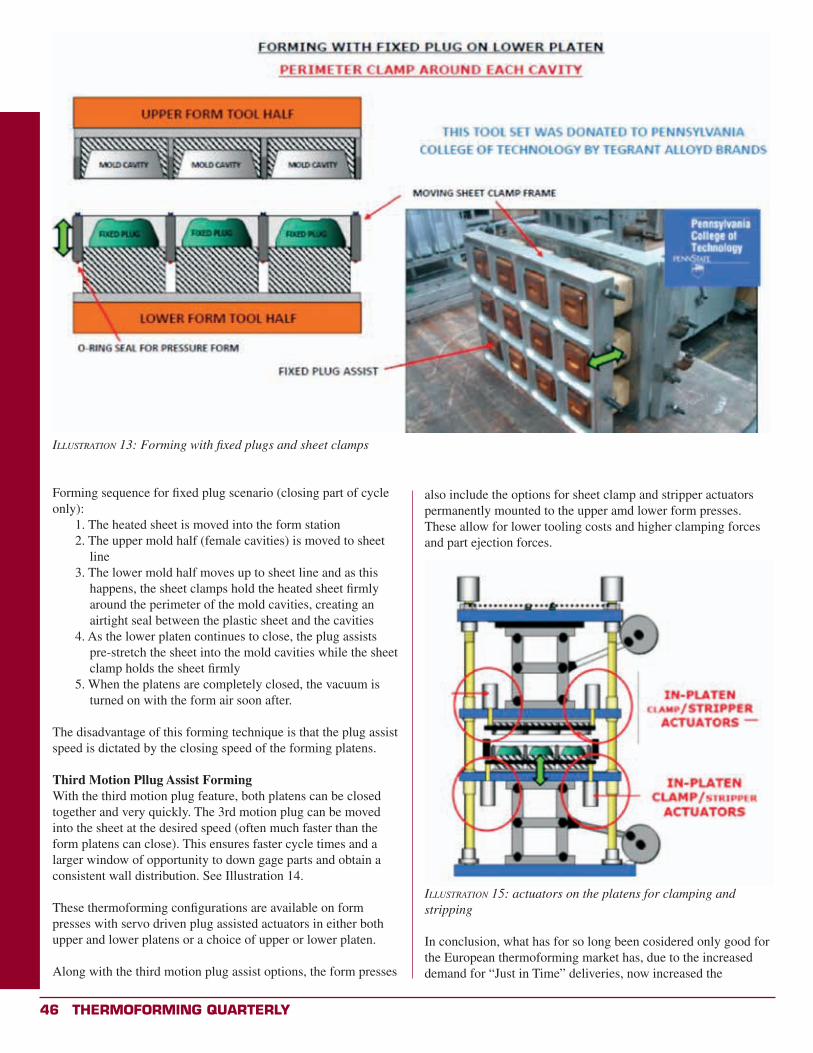
46 Thermoforming QuarTerly
illusTraTion 13: Forming with fixed plugs and sheet clamps
Forming sequence for fixed plug scenario (closing part of cycle only):
1. The heated sheet is moved into the form station2. The upper mold half (female cavities) is moved to sheet
line3. The lower mold half moves up to sheet line and as this
happens, the sheet clamps hold the heated sheet firmly around the perimeter of the mold cavities, creating an airtight seal between the plastic sheet and the cavities
4. As the lower platen continues to close, the plug assists pre-stretch the sheet into the mold cavities while the sheet clamp holds the sheet firmly
5. When the platens are completely closed, the vacuum is turned on with the form air soon after.
The disadvantage of this forming technique is that the plug assist speed is dictated by the closing speed of the forming platens.
Third Motion Pllug Assist FormingWith the third motion plug feature, both platens can be closed together and very quickly. The 3rd motion plug can be moved into the sheet at the desired speed (often much faster than the form platens can close). This ensures faster cycle times and a larger window of opportunity to down gage parts and obtain a consistent wall distribution. See Illustration 14.
These thermoforming configurations are available on form presses with servo driven plug assisted actuators in either both upper and lower platens or a choice of upper or lower platen.
Along with the third motion plug assist options, the form presses
also include the options for sheet clamp and stripper actuators permanently mounted to the upper amd lower form presses. These allow for lower tooling costs and higher clamping forces and part ejection forces.
illusTraTion 15: actuators on the platens for clamping and stripping
In conclusion, what has for so long been cosidered only good for the European thermoforming market has, due to the increased demand for “Just in Time” deliveries, now increased the
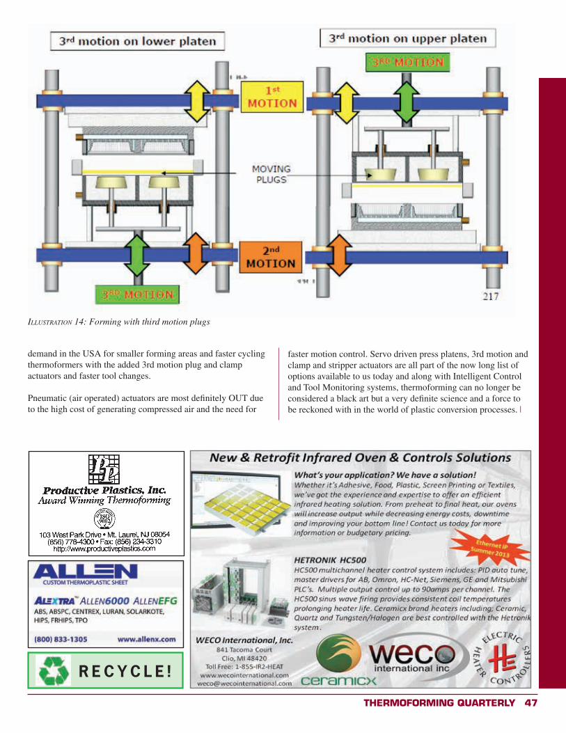
Thermoforming QuarTerly 47
illusTraTion 14: Forming with third motion plugs
demand in the USA for smaller forming areas and faster cycling thermoformers with the added 3rd motion plug and clamp actuators and faster tool changes.
Pneumatic (air operated) actuators are most definitely OUT due to the high cost of generating compressed air and the need for
R E C Y C L E !
faster motion control. Servo driven press platens, 3rd motion and clamp and stripper actuators are all part of the now long list of options available to us today and along with Intelligent Control and Tool Monitoring systems, thermoforming can no longer be considered a black art but a very definite science and a force to be reckoned with in the world of plastic conversion processes. x
48 Thermoforming QuarTerly
Eyetracking Study Report:Clamshells vs Paperboard Boxes
By Peter A. Gianniny, Business Manager, Thermoforming FilmsKlöckner Pentaplast America
ThermoformingQuarterly® Market Research
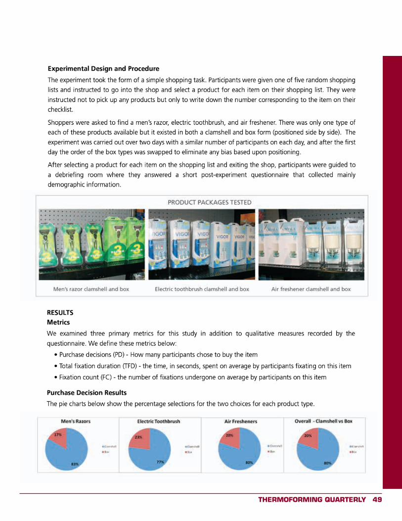
Thermoforming QuarTerly 49
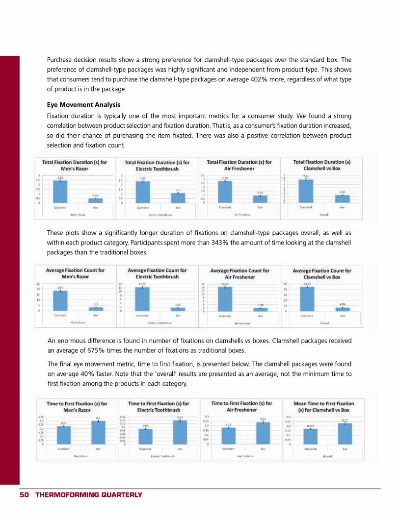
50 Thermoforming QuarTerly
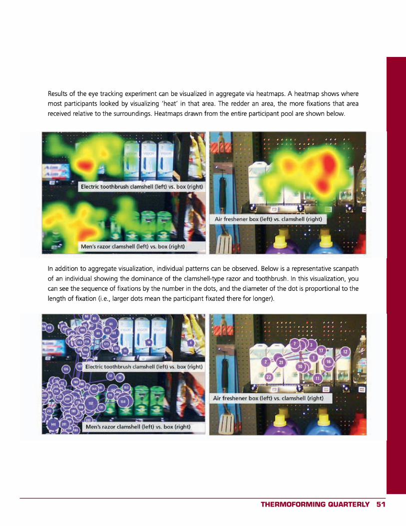
Thermoforming QuarTerly 51

52 Thermoforming QuarTerly
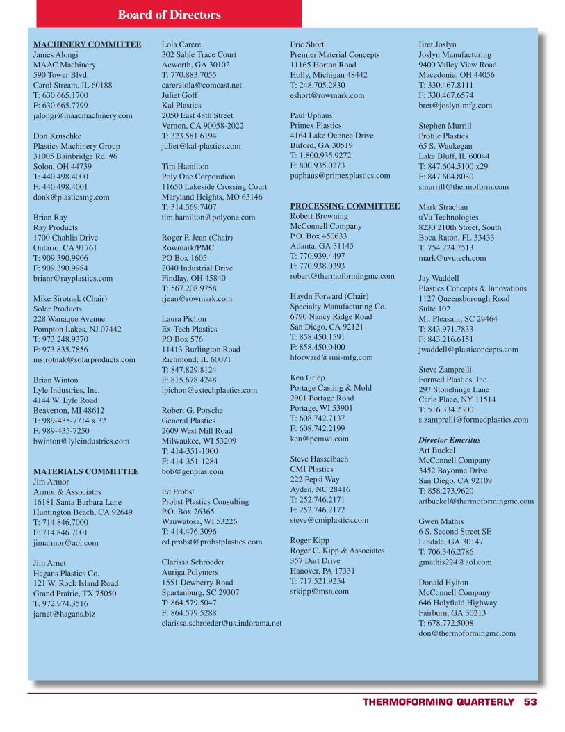
Thermoforming QuarTerly 53
Board of Directors
MACHINERY COMMITTEEJames AlongiMAAC Machinery590 Tower Blvd.Carol Stream, IL 60188T: 630.665.1700F: [email protected]
Don KruschkePlastics Machinery Group31005 Bainbridge Rd. #6Solon, OH 44739T: 440.498.4000F: [email protected]
Brian RayRay Products1700 Chablis DriveOntario, CA 91761T: 909.390.9906F: [email protected]
Mike Sirotnak (Chair)Solar Products228 Wanaque AvenuePompton Lakes, NJ 07442T: 973.248.9370F: [email protected]
Brian WintonLyle Industries, Inc.4144 W. Lyle RoadBeaverton, MI 48612T: 989-435-7714 x 32F: [email protected]
MATERIALS COMMITTEEJim ArmorArmor & Associates16181 Santa Barbara LaneHuntington Beach, CA 92649T: 714.846.7000F: [email protected]
Jim ArnetHagans Plastics Co.121 W. Rock Island RoadGrand Prairie, TX 75050T: [email protected]
Lola Carere302 Sable Trace CourtAcworth, GA 30102T: [email protected] GoffKal Plastics2050 East 48th StreetVernon, CA 90058-2022T: [email protected]
Tim HamiltonPoly One Corporation11650 Lakeside Crossing CourtMaryland Heights, MO 63146T: [email protected]
Roger P. Jean (Chair)Rowmark/PMCPO Box 16052040 Industrial DriveFindlay, OH 45840T: [email protected]
Laura PichonEx-Tech PlasticsPO Box 57611413 Burlington RoadRichmond, IL 60071T: 847.829.8124F: [email protected]
Robert G. PorscheGeneral Plastics2609 West Mill RoadMilwaukee, WI 53209T: 414-351-1000F: [email protected]
Ed ProbstProbst Plastics ConsultingP.O. Box 26365Wauwatosa, WI 53226T: [email protected]
Clarissa SchroederAuriga Polymers1551 Dewberry RoadSpartanburg, SC 29307T: 864.579.5047F: [email protected]
Eric ShortPremier Material Concepts11165 Horton RoadHolly, Michigan 48442T: [email protected]
Paul UphausPrimex Plastics4164 Lake Oconee DriveBuford, GA 30519T: 1.800.935.9272F: [email protected]
PROCESSING COMMITTEERobert BrowningMcConnell CompanyP.O. Box 450633Atlanta, GA 31145T: 770.939.4497F: [email protected]
Haydn Forward (Chair)Specialty Manufacturing Co.6790 Nancy Ridge RoadSan Diego, CA 92121T: 858.450.1591F: [email protected]
Ken GriepPortage Casting & Mold2901 Portage RoadPortage, WI 53901T: 608.742.7137F: [email protected]
Steve HasselbachCMI Plastics222 Pepsi WayAyden, NC 28416T: 252.746.2171F: [email protected]
Roger KippRoger C. Kipp & Associates357 Dart DriveHanover, PA 17331T: [email protected]
Bret JoslynJoslyn Manufacturing9400 Valley View RoadMacedonia, OH 44056T: 330.467.8111F: [email protected]
Stephen MurrillProfile Plastics65 S. WaukeganLake Bluff, IL 60044T: 847.604.5100 x29F: [email protected]
Mark StrachanuVu Technologies8230 210th Street, SouthBoca Raton, FL 33433T: [email protected]
Jay WaddellPlastics Concepts & Innovations1127 Queensborough RoadSuite 102Mt. Pleasant, SC 29464T: 843.971.7833F: [email protected]
Steve ZamprelliFormed Plastics, Inc.297 Stonehinge LaneCarle Place, NY 11514T: [email protected]
Director EmeritusArt BuckelMcConnell Company3452 Bayonne DriveSan Diego, CA 92109T: [email protected]
Gwen Mathis6 S. Second Street SELindale, GA 30147T: [email protected]
Donald HyltonMcConnell Company646 Holyfield HighwayFairburn, GA 30213T: [email protected]
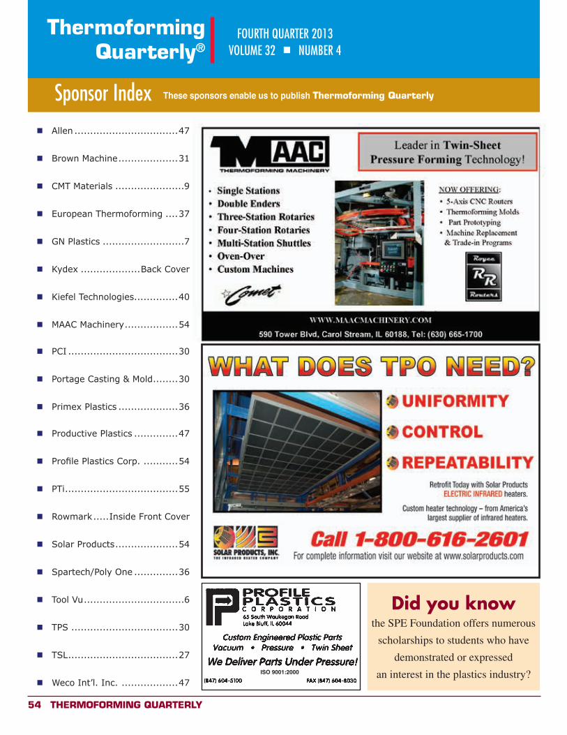
54 Thermoforming QuarTerly
ThermoformingQuarterly®
FOURTH QUARTER 2013VOLUME 32 n NUMBER 4
Sponsor Index These sponsors enable us to publish Thermoforming Quarterly
n Allen .................................47
n Brown Machine ...................31
n CMT Materials ......................9
n European Thermoforming ....37
n GN Plastics ..........................7
n Kydex ...................Back Cover
n Kiefel Technologies ..............40
n MAAC Machinery .................54
n PCI ...................................30
n Portage Casting & Mold ........30
n Primex Plastics ...................36
n Productive Plastics ..............47
n Profile Plastics Corp. ...........54
n PTi ....................................55
n Rowmark .....Inside Front Cover
n Solar Products ....................54
n Spartech/Poly One ..............36
n Tool Vu ................................6
n TPS ..................................30
n TSL ...................................27
n Weco Int’l. Inc. ..................47ISO 9001:2000
Did you know
the SPE Foundation offers numerous
scholarships to students who have
demonstrated or expressed
an interest in the plastics industry?
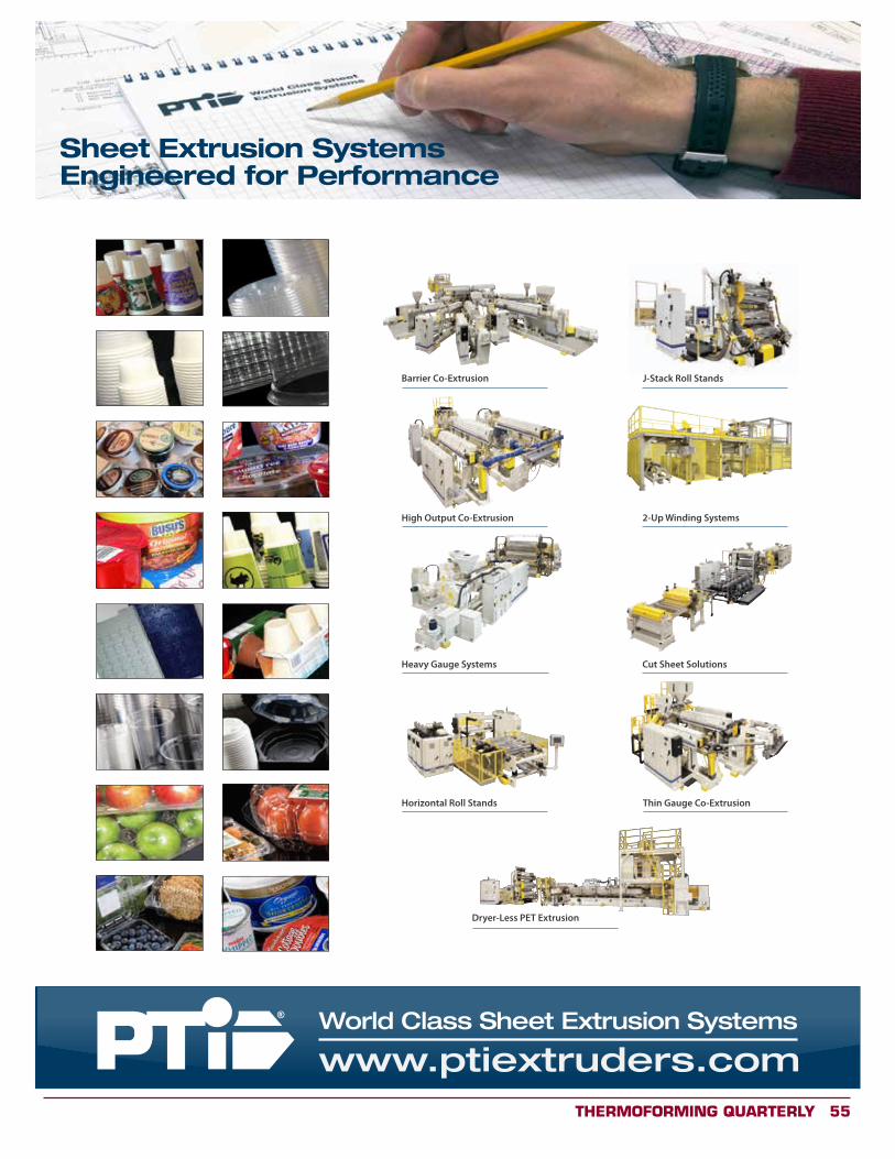
Thermoforming QuarTerly 55
World Class Sheet Extrusion Systems
Sheet Extrusion SystemsEngineered for Performance