Embed Size (px)
Citation preview
NOTES
Three-dimensional stress analysis of tubular joint using rezone technique
G. S. BHUYAN , M. AROCKIASAMY, AND K. MUNASWAMY Faculty of Engineering and Applied Science, Mernorinl U n i v e r s i ~ of Ne\vfouncllnrfcl, SI . John'.s, Njld., Cnnacia A I B 3x5
Received July 3, 1985 Revised manuscript accepted January 17. 1986
This note presents three-dimensional stress analysis results of a welded tubular T-joint under axial loading, using rezone technique. The rezone technique is used to reduce computer storage requirements, as well as solution costs, that result from the large number of degrees-of-freedom associated with three-dimensional analysis of the entire joint using solid elements. The hot-spot region around the weld toe and the weld reinforcement are modelled using three-dimensional incompatible 8-node brick and 6-node prism elements. The boundary nodal displacements for the rezoned model arc obtained from plate analysis of the entire joint. The boundary values, at the plate-to-solid element transition zone, are distributed between two solid element nodes maintaining boundary displacement compatibility. The stresses at the critical lines. obtained from the rezoned analysis, are compared with those of the entire three-dimensional and plate model analyses.
Key words: tubular joint, rezoned model, transition zone, boundary displacement compatibility, incompatible elements.
L'article presente les resultats d'une analyse tridimensionnelle des contraintes exlstant dans un assemblage soude en T@ de sections tubulaires soumis a I'action de charges axiales. La methode du rezonage est utilisCc afin de diminuer la memoire necessaire aussi bien que le coDt d'exCcution rtsultant du grand nombre de degres de liberte associC une analyse tri- dimensionnelle de la totaliti de I'assemblage en utilisant des 6ICments solides. La zone critique, autour du talon et du renforcement de la soudure, est modClisCe au moyen d'ildments incompatibles, des blocs ii 8 noeuds et des prismes a 6 noeuds. Les dtplacements des noeuds frontikres sont obtenus en appliquant la thiorie des plaques a la totalit6 de I'assemblage. Les valeurs frontikres, dans la zone de transition entre les elements plans et les ClCments solides, sont distributes entre les noeuds d'ClCments solides afin de conserver la compatibilitk des deplaccments. Les contraintes aux lignes de rupture obtcnues de cette analyse sont comparees B celles d'une analyse utilisant des 6l&mcnts plans et des 6ICments solides.
Mots clPs: assemblage d'Cltments tubulaires, modkle rezone, zone de transition, compatibilite des dCplacements frontikres, Climents incompatibles.
[Traduit par la revue]
Can. J . Civ. Eng. 13. 382-385 (1986)
Introduction
Because of the relative con~plexity of the geometrical config- uration of tubular intersections, as well as the thin-shell theory governing their behaviour, reliable prediction of stresses in such joints by analytical techniques has been proven to be difficult. The finite element method seemed to offer a natural solution for modelling complex geometries and boundary con- ditions. Existing literature on the analysis of the tubular joint is limited to the use of plate/shell elements, which neglects the displacement variation across the wall thickness. Also, plate idealization does not permit the consideration of weld profile and the actual brace-chord intersection. The present in- vestigation describes the use of the rezone technique to obtain an accurate estimate of stresses at the intersection of the brace and chord, including through-thickness and weld reinforce- ment effects.
Rezone modelling
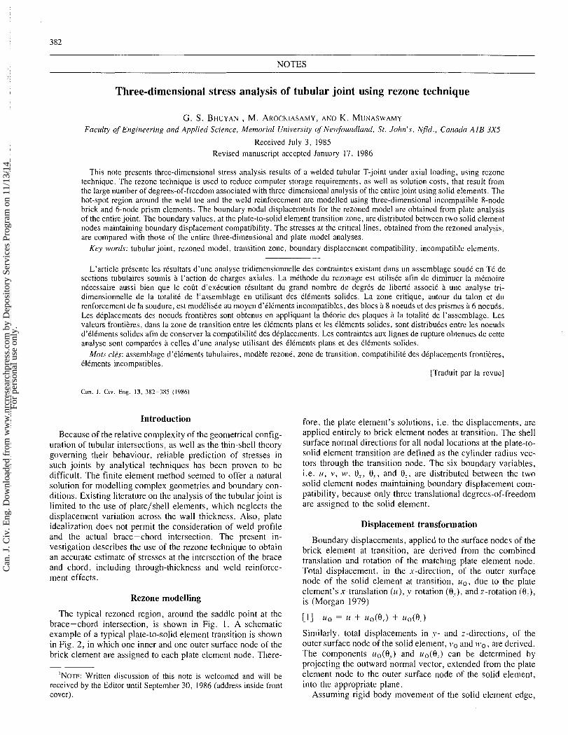
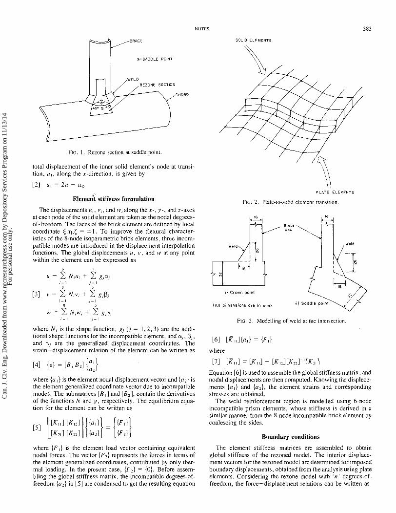
The typical rezoned region, around the saddle point at the brace-chord intersection, is shown in Fig. 1. A schematic example of a typical plate-to-solid element transition is shown in Fig. 2, in which one inner and one outer surface node of the brick element are assigned to each plate element node. There-
'NOTE: Written discussion of this note is welcomed and will be received by the Editor until September 30, 1986 (address inside front cover).
fore, the plate element's solutions, i.e. the displacen~ents, are applied entirely to brick element nodes at transition. The shell surface normal directions for all nodal locations at the plate-to- solid element transition are defined as the cylinder radius vec- tors through the transition node. The six boundary variables, i.e. u , v , MI, 0 , , O,., and O,, are distributed between the two solid element nodes maintaining boundary displacelnent com- patibility, because only three translational degrees-of-freedom are assigned to the solid element.
Displacement transformation
Boundary displacements, applied to the surface nodes of the brick element at transition, are derived from the combined translation and rotation of the matching plate element node. Total displacement, in the x-direction, of the outer surface node of the solid element at transition, 110, due to the plate element's .r-translation (u ) , y-rotation (O,.). and z-rotation (O:), is (Morgan 1979)
Similarly, total displacements in y- and z-directions, of the outer surface node of the solid element, v o and nVo , are derived. The components uo(O,) and uo(O,) can be determined by projecting the outward normal vector, extended from the plate element node to the outer surface node of the solid element, into the appropriate plane.
Assuming rigid body movement of the solid element edge,
Can
. J. C
iv. E
ng. D
ownl
oade
d fr
om w
ww
.nrc
rese
arch
pres
s.co
m b
y D
epos
itory
Ser
vice
s Pr
ogra
m o
n 11
/13/
14Fo
r pe
rson
al u
se o
nly.
NOTES
S=SADOLE POINT
SOLID ELEMENTS
REZONE SECTION
CHORD
FIG. I . Rezone section at saddle point.
total displacement of the inner solid element's node at transi- tion, ul, along the x-direction, is given by
~ l e m e i t stiffness formulation
The displacements n,, v , , and w, along the x-, y- , and z-axes at each node of the solid element are taken as the nodal degrees- of-freedom. The faces of the brick element are defined by local coordinate .$,q,< = k 1 . To improve the flexural character- istics of the 8-node isoparametric brick elements, three incom- patible modes are introduced in the displacement interpolation functions. The global displacements u, v , and w at any point within the element can be expressed as
where N i is the shape function, g, (j = 1,2 ,3) are the addi- tional shape functions for the incompatible element, and a,, P,, and y, are the generalized displacement coordinates. The strain-displacement relation of the element can be written as
where {aI } is the element nodal displacement vector and {az} is the element generalized coordinate vector due to incompatible modes. The submatrices [BI] and [B2], contain the derivatives of the functions N and g, respectively. The equilibrium equa- tion for the element can be written as
PLATE ELEMENTS
FIG. 2. Plate-to-solid element transition.
I) Crown point
(All d ~ m e n s i o n s a re in mm) i i ) Sadd le '----,I point
FIG. 3. Modelling of weld at the intersection.
[61 [ K l l l { a l } = {FI}
where
171 [Ell] = CKllI - [K121[K221T1[K?11
Equation [6] is used to assemble the global stiffness matrix, and nodal displacements are then computed. Knowing the displace- ments { a l } and {a2}, the element strains and corresponding stresses are obtained.
The weld reinforcement region is modelled using 6-node incompatible prism elements, whose stiffness is derived in a similar manner from the 8-node incompatible brick element by coalescing the sides.
Boundary conditions
where {F I } is the element load vector containing equivalent The element stiffness matrices are assembled to obtain nodal forces. The vector {F2} represents the forces in terms of global stiffness of the rezoned model. The interior displace- the element generalized coordinates, contributed by only ther- ment vectors for the rezoned model are determined for imposed ma1 loading. In the present case, {F2} = {O}. Before assem- boundary displacements, obtained from the analysis using plate bling the global stiffness matrix, the incompatible degrees-of- elements. Considering the rezone model with 'n' degrees-of- freedom {a,} in [5] are condensed to get the resulting equation freedom, the force-displacement relations can be written as
Can
. J. C
iv. E
ng. D
ownl
oade
d fr
om w
ww
.nrc
rese
arch
pres
s.co
m b
y D
epos
itory
Ser
vice
s Pr
ogra
m o
n 11
/13/
14Fo
r pe
rson
al u
se o
nly.
CAN. J . CIV. ENG. VOL. 13. 1986
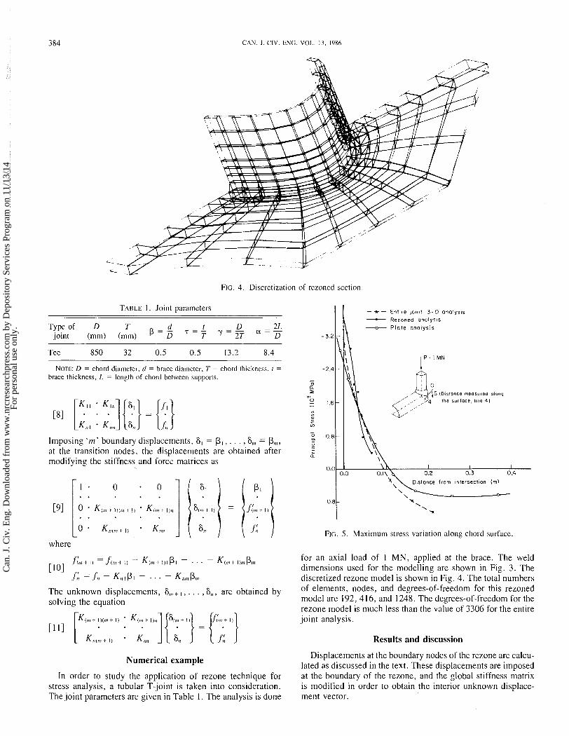
FIG. 4. Discretization of rezoned section.
TABLE I. Joint parameters
Type of D T (1 I D 2L p = - 7 2 - joint (mm) (mm) D T ' = T T a = - D
Tee 850 32 0.5 0.5 13.2 8.4
NOTE: D = chord dii~meter, (1 = brace diameter. T = chord thickness, t = brace thickness, L = length of chord between supports.
Imposing 'm' boundary displacements, S1 = P I , . . . ,6,,, = p ,,,, at the transition nodes, the displacements are obtained after modifying the stiffness and force matrices as
where
[I01 ,f:,,, 1 1 1 f(,,, .t 1) - K,,,, -1. 111 - . . . - K(,,, 1 I),,, P,,, f:l = .fl, - K,, I p I - . . . - K,,,,, P,,,
The unknown displacements, 6 ,,,., . . . , S,,, are obtained by solving the equation
Numerical example
In order to study the application of rezone technique for stress analysis, a tubular T-joint is taken into consideration. The joint parameters are given in Table I. The analysis is done
I I - +- Entlre lolnt 3 - D analys~s - Rezoned analysls
P la te analysis
S (Dlstonce measured o iong
the sur face , line 4 )
D~slance from ~nlersectlon (rn)
0.8 \X. \ \
-n
FIG. 5. Maximum stress variation along chord surface.
for an axial Ioad of 1 MN, applied at the brace. The weld dimensions used for the modelling are shown in Fig. 3. The discretized rezone model is shown in Fig. 4. The total numbers of elements, nodes, and degrees-of-freedom for this rezoned model are I92 ,4 16, and 1248. The degrees-of-freedom for the rezone model is much less than the value of 3306 for the entire joint analysis.
Results and discussion
Displacements at the boundary nodes of the rezone are calcu- lated as discussed in the text. These displacements are imposed at the boundary of the rezone, and the global stiffness matrix is modified in order to obtain the interior unknown displace- ment vector.
Can
. J. C
iv. E
ng. D
ownl
oade
d fr
om w
ww
.nrc
rese
arch
pres
s.co
m b
y D
epos
itory
Ser
vice
s Pr
ogra
m o
n 11
/13/
14Fo
r pe
rson
al u
se o
nly.
- -, - Entire joint 3 - D onolysis - Rezoned onolysls - 4.0 -0- P l a t e onolysis
Distance from ~ntersectlon (m)
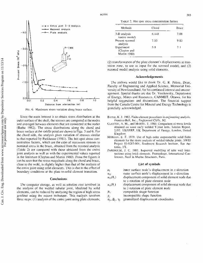
FIG. 6. Maximum stress variation along brace surface.
Since the main interest is to obtain stress distribution at the outer surface of the shell, the stresses are conlputed at the nodes and averaged between elements that are connected at the nodes (Bathe 1982). The stress distributions along the chord and brace surface at the saddle point are shown in Figs. 5 and 6. For the chord side, the analysis gives variation of stresses similar to that reported by Parkhouse (1981). The hot-spot stress con- centration factors, which are the ratio of maximum stresses to nominal stress in the brace, obtained from the rezoned analysis (Table 2) are compared with those obtained from the entire joint analysis as well as with the experimental values reported in the literature (Clayton and Martin 1980). From the figures it can be seen that the stress magnitude along the chord and brace, close to the weld, is slightly higher than that of the analysis of the entire joint using solid elements. This is due to the effect of boundary conditions at the plate-to-solid element transition.
Conclusions
The computer storage, as well as solution cost involved in the analysis of the welded tubular joint, idealized by solid elements, can be reduced by analyzing the region of high stress gradient using the rezone technique. This analysis involves three steps: ( I ) analysis of the entire joint using plate elements;
TABLE 2. Hot-spot stress concentration factors
Methods Chord Brace
3-D analysis 6.448 7.08 (entire model)
Present rezoned 7.53 9.83 analysis
Experiment 5.8 7.1 (Clayton and Martin 1980)
(2) transformation of the plate element's displacements at tran- sition zone, to use as input for the rezoned model; and (3) rezoned model analysis using solid elements.
Acknowledgements
The authors would like to thank Dr. G. R. Peters, Dean, Faculty of Engineering and Applied Science, Memorial Uni- versity of Newfoundland, for his continued interest and encour- agement. Special thanks are due Dr. Vosikovsky, Department of Energy, Mines and Resources, CANMET, Ottawa, for his helpful suggestions and discussions. The financial support from the Canada Centre for Mineral and Energy Technology is gratefully acknowledged.
BATHE. K. J . 1982. Finite clement procedures in engineering analysis. Prenticc-Hall, Inc., Englcwood Cliffs. N J .
CLAYTON, A . M.. and MARTIN, T. 1980. Comparison of stress levels obtained on some early welded 'l'-joint tests. Interim Report, 2/07, UKOSRP, UK Department of Energy. London, United Kingdom.
MORGAN, E. F. 1979. Use of high ordel. isoparametric solid finite elements for the stress analysis of wcldcd tubular joints. SWRl Project 03-9217-001, Southwest Rcscarch Institute, San An- tonio, TX.
PARKI-IOUSE. J . C. 1981. Improved modelling of tube wall inter- sections using brick elements. Proceedings. International Con- ference, Steel in Marine Structures. Paris.
List of symbols
11 I inner surface node's displacement in x-direction 11 o outer surface node's displacement in x-direction uo(O,.) displacement component of solid element node due
to y-rotation of plate element node u,(0,) displacement component of solid element node due
to z-rotation of plate element node Ni con~patible shape function gj incon~patible shape function aj, P,, yi generalized displacement coordinates
Can
. J. C
iv. E
ng. D
ownl
oade
d fr
om w
ww
.nrc
rese
arch
pres
s.co
m b
y D
epos
itory
Ser
vice
s Pr
ogra
m o
n 11
/13/
14Fo
r pe
rson
al u
se o
nly.