Embed Size (px)
Citation preview
ASYNCHRONOUSTHREE-PHASE, SINGLE-PHASE ANDELECTROMAGNETICBRAKE MOTORS
EFFICIENCY CLASSACCORDING TO IEC 60034-30
2nd edition
ww
w.st
udid
f.co
m sacosgra
Ed.
MOT
ORES
CEM
ER 0
6/19
0.5
. W
e re
serv
e th
e rig
ht t
o m
ake
chan
ges
wit
hout
prio
r no
tice
.
sacosgraMECHANICAL SEALS FOR ROTARY SHAFTSAC ELECTRIC MOTORS: Single-phase / Three-phase / Self-braking / Anti-explosion / Flameproof / Variable speed DRUM MOTORS AND MOTORIZED DRUMSGEARBOXES: Worm gearbox / Pre-reduction / Double worm gearbox / Planetary speed variators / Coaxials / Speci�c
Ctra. de Banyoles a Figueres, Km 9 _ Telf. - +34 972 597 807Skype: cosgra.sa _ Fax +34 972 597 [email protected] _ 17832 CRESPIÀ (Girona) _ SPAINApartado 100 _ 17820 BANYOLES (Girona)(E) Esponellà Latitude: 42º10’42.6”N Longitude: 2º48’04.9”E Altitude: 120 m.
Sociedad Comercial COSGRA LATAM S.P.A. Alcalde Guzmán, 0121 - Quilicura - Santiago. [email protected] Telf: +56 944506061_+56 944644826_+56 956505381
w w w. c o s g r a . c o m
Three-phase
Single-phase
Three-phase with electromagnetic brake
Forced ventilation unit
IE3 Premium efficiency IE2 High efficiencyIE1 Standard efficiency Increased power
Permanent capacitorDouble capacitor(centrifugal switch)
DC brake coilAC brake coil
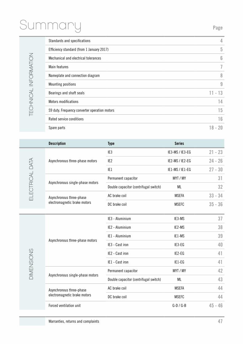
Summary Page
Standards and specifications 4
Efficiency standard (from 1 January 2017) 5
Mechanical and electrical tolerances 6
Main features 7
Nameplate and connection diagram 8
Mounting positions 9
Bearings and shaft seals 11 - 13
Motors modifications 14
S9 duty. Frequency converter operation motors 15
Rated service conditions 16
Spare parts 18 - 20
Description Type Series
Asynchronous three-phase motors
IE3 IE3-MS / IE3-EG 21 - 23
IE2 IE2-MS / IE2-EG 24 - 26
IE1 IE1-MS / IE1-EG 27 - 30
Asynchronous single-phase motorsPermanent capacitor MYT / MY 31
Double capacitor (centrifugal switch) ML 32
Asynchronous three-phaseelectromagnetic brake motors
AC brake coil MSEFA 33 - 34
DC brake coil MSEFC 35 - 36
Asynchronous three-phase motors
IE3 - Aluminium IE3-MS 37
IE2 - Aluminium IE2-MS 38
IE1 - Aluminium IE1-MS 39
IE3 - Cast iron IE3-EG 40
IE2 - Cast iron IE2-EG 41
IE1 - Cast iron IE1-EG 41
Asynchronous single-phase motorsPermanent capacitor MYT / MY 42
Double capacitor (centrifugal switch) ML 43
Asynchronous three-phaseelectromagnetic brake motors
AC brake coil MSEFA 44
DC brake coil MSEFC 44
Forced ventilation unit G-D / G-B 45 - 46
Warranties, returns and complaints 47
DIM
EN
SIO
NS
ELE
CTR
ICAL
DAT
ATE
CH
NIC
AL IN
FOR
MAT
ION
4
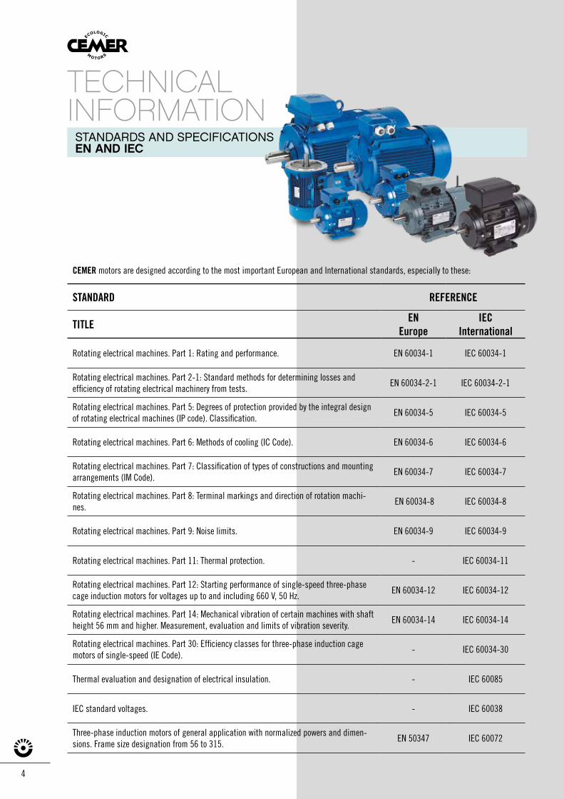
STANDARDS AND SPECIFICATIONSEN AND IEC
TECHNICALINFORMATION
CEMER motors are designed according to the most important European and International standards, especially to these:
STANDARD REFERENCE
TITLE ENEurope
IECInternational
Rotating electrical machines. Part 1: Rating and performance. EN 60034-1 IEC 60034-1
Rotating electrical machines. Part 2-1: Standard methods for determining losses and efficiency of rotating electrical machinery from tests.
EN 60034-2-1 IEC 60034-2-1
Rotating electrical machines. Part 5: Degrees of protection provided by the integral design of rotating electrical machines (IP code). Classification.
EN 60034-5 IEC 60034-5
Rotating electrical machines. Part 6: Methods of cooling (IC Code). EN 60034-6 IEC 60034-6
Rotating electrical machines. Part 7: Classification of types of constructions and mounting arrangements (IM Code).
EN 60034-7 IEC 60034-7
Rotating electrical machines. Part 8: Terminal markings and direction of rotation machi-nes.
EN 60034-8 IEC 60034-8
Rotating electrical machines. Part 9: Noise limits. EN 60034-9 IEC 60034-9
Rotating electrical machines. Part 11: Thermal protection. - IEC 60034-11
Rotating electrical machines. Part 12: Starting performance of single-speed three-phase cage induction motors for voltages up to and including 660 V, 50 Hz.
EN 60034-12 IEC 60034-12
Rotating electrical machines. Part 14: Mechanical vibration of certain machines with shaft height 56 mm and higher. Measurement, evaluation and limits of vibration severity.
EN 60034-14 IEC 60034-14
Rotating electrical machines. Part 30: Efficiency classes for three-phase induction cage motors of single-speed (IE Code).
- IEC 60034-30
Thermal evaluation and designation of electrical insulation. - IEC 60085
IEC standard voltages. - IEC 60038
Three-phase induction motors of general application with normalized powers and dimen-sions. Frame size designation from 56 to 315.
EN 50347 IEC 60072
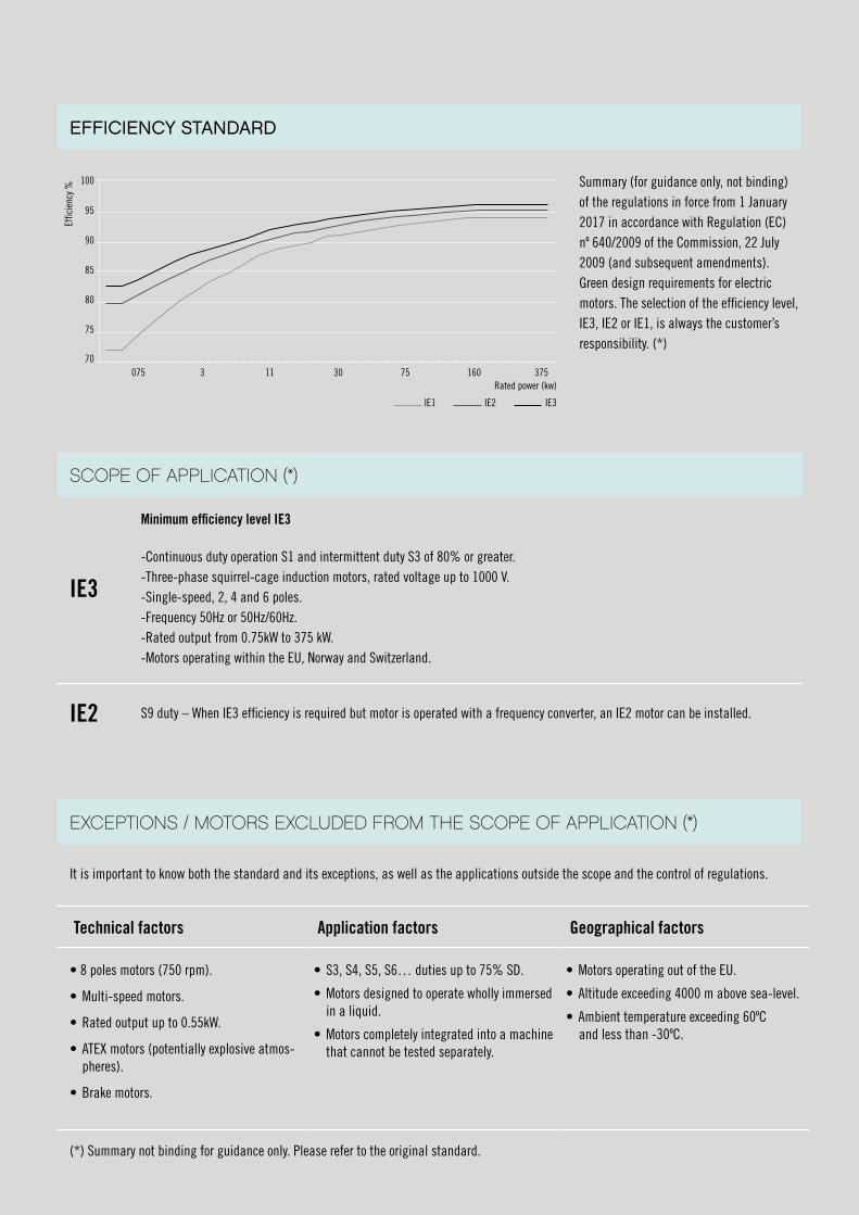
SCOPE OF APPLICATION (*)
IE3
Minimum efficiency level IE3
-Continuous duty operation S1 and intermittent duty S3 of 80% or greater.-Three-phase squirrel-cage induction motors, rated voltage up to 1000 V.-Single-speed, 2, 4 and 6 poles.-Frequency 50Hz or 50Hz/60Hz.-Rated output from 0.75kW to 375 kW.-Motors operating within the EU, Norway and Switzerland.
IE2 S9 duty – When IE3 efficiency is required but motor is operated with a frequency converter, an IE2 motor can be installed.
It is important to know both the standard and its exceptions, as well as the applications outside the scope and the control of regulations.
Technical factors Application factors Geographical factors
• 8 poles motors (750 rpm).
• Multi-speed motors.
• Rated output up to 0.55kW.
• ATEX motors (potentially explosive atmos-pheres).
• Brake motors.
• S3, S4, S5, S6… duties up to 75% SD.
• Motors designed to operate wholly immersed in a liquid.
• Motors completely integrated into a machine that cannot be tested separately.
• Motors operating out of the EU.
• Altitude exceeding 4000 m above sea-level.
• Ambient temperature exceeding 60ºC and less than -30ºC.
(*) Summary not binding for guidance only. Please refer to the original standard.
Summary (for guidance only, not binding) of the regulations in force from 1 January 2017 in accordance with Regulation (EC)nº 640/2009 of the Commission, 22 July 2009 (and subsequent amendments).Green design requirements for electric motors. The selection of the efficiency level, IE3, IE2 or IE1, is always the customer’s responsibility. (*)
EFFICIENCY STANDARD
EXCEPTIONS / MOTORS EXCLUDED FROM THE SCOPE OF APPLICATION (*)
100
95
90
85
80
75
70075 3 11 30 75 160 375
Rated power (kw)
IE3IE2IE1
Effic
ienc
y %
6
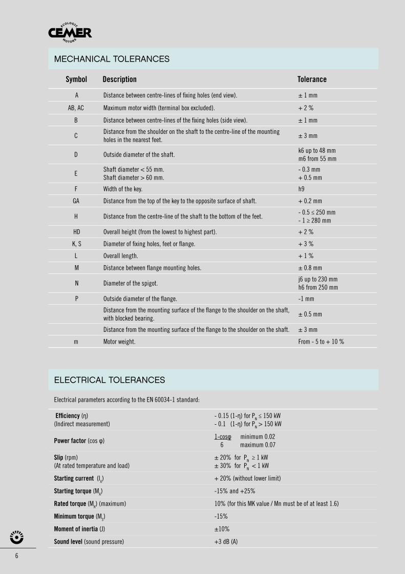
Symbol Description Tolerance
A Distance between centre-lines of fixing holes (end view). ± 1 mm
AB, AC Maximum motor width (terminal box excluded). + 2 %
B Distance between centre-lines of the fixing holes (side view). ± 1 mm
C Distance from the shoulder on the shaft to the centre-line of the mounting holes in the nearest feet.
± 3 mm
D Outside diameter of the shaft.k6 up to 48 mmm6 from 55 mm
EShaft diameter < 55 mm.Shaft diameter > 60 mm.
- 0.3 mm+ 0.5 mm
F Width of the key. h9
GA Distance from the top of the key to the opposite surface of shaft. + 0.2 mm
H Distance from the centre-line of the shaft to the bottom of the feet.- 0.5 ≤ 250 mm- 1 ≥ 280 mm
HD Overall height (from the lowest to highest part). + 2 %
K, S Diameter of fixing holes, feet or flange. + 3 %
L Overall length. + 1 %
M Distance between flange mounting holes. ± 0.8 mm
N Diameter of the spigot.j6 up to 230 mmh6 from 250 mm
P Outside diameter of the flange. -1 mm
Distance from the mounting surface of the flange to the shoulder on the shaft, with blocked bearing.
± 0.5 mm
Distance from the mounting surface of the flange to the shoulder on the shaft. ± 3 mm
m Motor weight. From - 5 to + 10 %
Electrical parameters according to the EN 60034-1 standard:
Efficiency (η) (Indirect measurement)
- 0.15 (1-η) for PN ≤ 150 kW- 0.1 (1-η) for PN > 150 kW
Power factor (cos φ)1-cosφ minimum 0.02 6 maximum 0.07
Slip (rpm) (At rated temperature and load)
± 20% for PN ≥ 1 kW± 30% for PN < 1 kW
Starting current (IA) + 20% (without lower limit)
Starting torque (MA) -15% and +25%
Rated torque (MK) (maximum) 10% (for this MK value / Mn must be of at least 1.6)
Minimum torque (MS) -15%
Moment of inertia (J) ±10%
Sound level (sound pressure) +3 dB (A)
MECHANICAL TOLERANCES
ELECTRICAL TOLERANCES
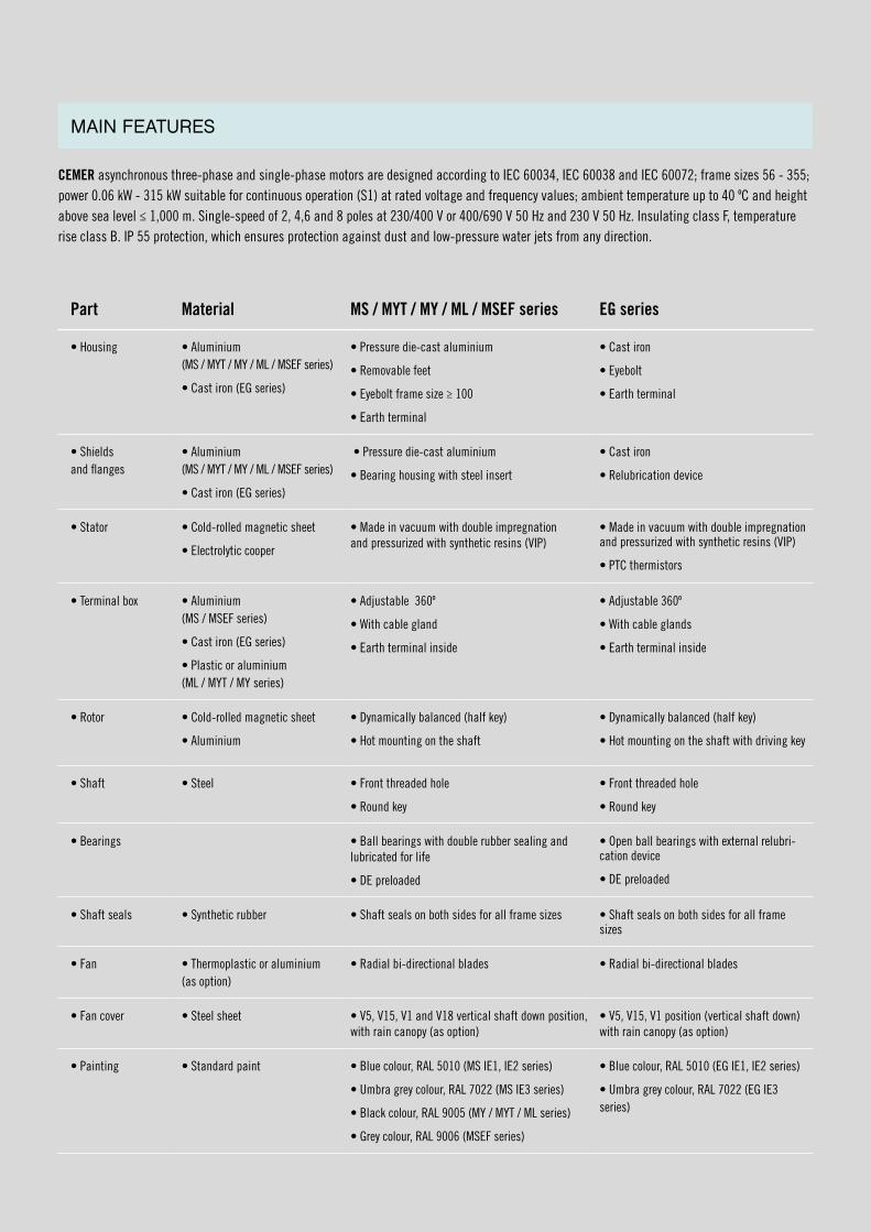
CEMER asynchronous three-phase and single-phase motors are designed according to IEC 60034, IEC 60038 and IEC 60072; frame sizes 56 - 355; power 0.06 kW - 315 kW suitable for continuous operation (S1) at rated voltage and frequency values; ambient temperature up to 40 ºC and height above sea level ≤ 1,000 m. Single-speed of 2, 4,6 and 8 poles at 230/400 V or 400/690 V 50 Hz and 230 V 50 Hz. Insulating class F, temperature rise class B. IP 55 protection, which ensures protection against dust and low-pressure water jets from any direction.
Part Material MS / MYT / MY / ML / MSEF series EG series
• Housing • Aluminium(MS / MYT / MY / ML / MSEF series)
• Cast iron (EG series)
• Pressure die-cast aluminium
• Removable feet
• Eyebolt frame size ≥ 100
• Earth terminal
• Cast iron
• Eyebolt
• Earth terminal
• Shieldsand flanges
• Aluminium(MS / MYT / MY / ML / MSEF series)
• Cast iron (EG series)
• Pressure die-cast aluminium
• Bearing housing with steel insert
• Cast iron
• Relubrication device
• Stator • Cold-rolled magnetic sheet
• Electrolytic cooper
• Made in vacuum with double impregnation and pressurized with synthetic resins (VIP)
• Made in vacuum with double impregnation and pressurized with synthetic resins (VIP)
• PTC thermistors
• Terminal box • Aluminium(MS / MSEF series)
• Cast iron (EG series)
• Plastic or aluminium (ML / MYT / MY series)
• Adjustable 360º
• With cable gland
• Earth terminal inside
• Adjustable 360º
• With cable glands
• Earth terminal inside
• Rotor • Cold-rolled magnetic sheet
• Aluminium
• Dynamically balanced (half key)
• Hot mounting on the shaft
• Dynamically balanced (half key)
• Hot mounting on the shaft with driving key
• Shaft • Steel • Front threaded hole
• Round key
• Front threaded hole
• Round key
• Bearings • Ball bearings with double rubber sealing and lubricated for life
• DE preloaded
• Open ball bearings with external relubri-cation device
• DE preloaded
• Shaft seals • Synthetic rubber • Shaft seals on both sides for all frame sizes • Shaft seals on both sides for all frame sizes
• Fan • Thermoplastic or aluminium (as option)
• Radial bi-directional blades • Radial bi-directional blades
• Fan cover • Steel sheet • V5, V15, V1 and V18 vertical shaft down position, with rain canopy (as option)
• V5, V15, V1 position (vertical shaft down) with rain canopy (as option)
• Painting • Standard paint • Blue colour, RAL 5010 (MS IE1, IE2 series)
• Umbra grey colour, RAL 7022 (MS IE3 series)
• Black colour, RAL 9005 (MY / MYT / ML series)
• Grey colour, RAL 9006 (MSEF series)
• Blue colour, RAL 5010 (EG IE1, IE2 series)
• Umbra grey colour, RAL 7022 (EG IE3 series)
MAIN FEATURES
8
IE3IEC/EN 60034-1
Frame: IE2-EGQ 180 M2
DE Brg. 6311 C3 NDE Brg. 6311 C3
3-Mot. 0000000000000 Conn.Delta - Δ
Star - Y
IM B35 I.Clas. 155 (F) IP 55 S1 40 ºC 203 Kg
50 Hz 22 kW400/600 V D/Y Cosϕ 0,9038,7 / 22,4 A 2940 min-1
IE2-91,3%
60 Hz 26,4 kW480 V D/Y Cosϕ 0,9038,7A 3530 min-1
IE2-91,3%
W2 U2 V2
W2 U2 V2
U1 V1 W1
U1 V1 W1
2 1
76
83
4
5
W2 U2 V2W2 U2 V2
U1 V1 W1 U1
L1
L2
Z2 U2 V2
U1 V1 Z1
K
Cst
Crun
V1 W1
W2 U2 V2
U1 V1 W1
Z2 U2 V2
U1 V1 Z1
L1(R)
L2(S)
L3(T)
L1(R)
L2(S)
L3(T)
L2
C
L1
Z2 U2 V2
U1 V1 Z1
L2
C
L1
L2
Z2 U2 V2
U1 V1 Z1
K
Cst
Crun
L1
W2 U2 V2W2 U2 V2
U1 V1 W1 U1
L1
L2
Z2 U2 V2
U1 V1 Z1
K
Cst
Crun
V1 W1
W2 U2 V2
U1 V1 W1
Z2 U2 V2
U1 V1 Z1
L1(R)
L2(S)
L3(T)
L1(R)
L2(S)
L3(T)
L2
C
L1
Z2 U2 V2
U1 V1 Z1
L2
C
L1
L2
Z2 U2 V2
U1 V1 Z1
K
Cst
Crun
L1
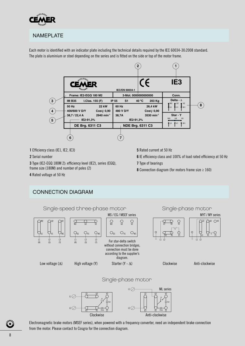
Each motor is identified with an indicator plate including the technical details required by the IEC 60034-30:2008 standard. The plate is aluminium or steel depending on the series and is fitted on the side or top of the motor frame.
Electromagnetic brake motors (MSEF series), when powered with a frequency converter, need an independent brake connectionfrom the motor. Please contact to Cosgra for the connection diagram.
1 Efficiency class (IE1, IE2, IE3)
2 Serial number
3 Type (IE2-EGQ 180M 2): efficiency level (IE2), series (EGQ), frame size (180M) and number of poles (2)
4 Rated voltage at 50 Hz
5 Rated current at 50 Hz
6 IE efficiency class and 100% of load rated efficiency at 50 Hz
7 Type of bearings
8 Connection diagram (for motors frame size ≥ 160)
Low voltage (Δ) Clockwise Anti-clockwiseHigh voltage (Y) Starter (Y - Δ)
For star-delta switch without connection bridges,
connection must be done according to the supplier’s
diagram.
MS / EG / MSEF series MYT / MY series
CONNECTION DIAGRAM
NAMEPLATE
Single-speed three-phase motor
Single-phase motor
Single-phase motor
Clockwise Anti-clockwise
ML series
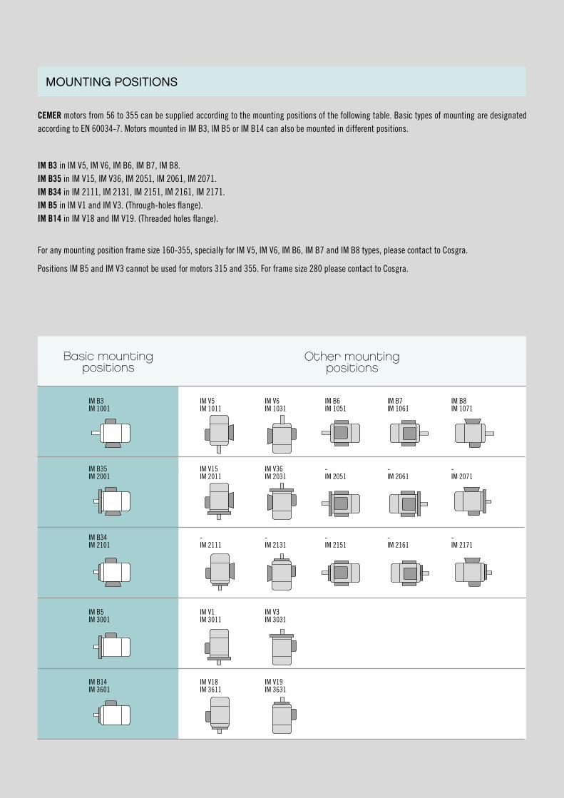
CEMER motors from 56 to 355 can be supplied according to the mounting positions of the following table. Basic types of mounting are designated according to EN 60034-7. Motors mounted in IM B3, IM B5 or IM B14 can also be mounted in different positions.
IM B3 in IM V5, IM V6, IM B6, IM B7, IM B8.IM B35 in IM V15, IM V36, IM 2051, IM 2061, IM 2071.IM B34 in IM 2111, IM 2131, IM 2151, IM 2161, IM 2171.IM B5 in IM V1 and IM V3. (Through-holes flange).IM B14 in IM V18 and IM V19. (Threaded holes flange).
For any mounting position frame size 160-355, specially for IM V5, IM V6, IM B6, IM B7 and IM B8 types, please contact to Cosgra.
Positions IM B5 and IM V3 cannot be used for motors 315 and 355. For frame size 280 please contact to Cosgra.
MOUNTING POSITIONS
Other mountingpositions
IM B3IM 1001
IM V5IM 1011
IM V6IM 1031
IM B6IM 1051
IM B7IM 1061
IM B8IM 1071
IM B35IM 2001
IM V15IM 2011
IM V36IM 2031
-IM 2051
-IM 2061
-IM 2071
IM B34IM 2101
-IM 2111
-IM 2131
-IM 2151
-IM 2161
-IM 2171
IM B5IM 3001
IM V1IM 3011
IM V3IM 3031
IM B14IM 3601
IM V18IM 3611
IM V19IM 3631
Basic mounting positions
10
MS / MYT / MY / ML / MSEF MOTORSERIES
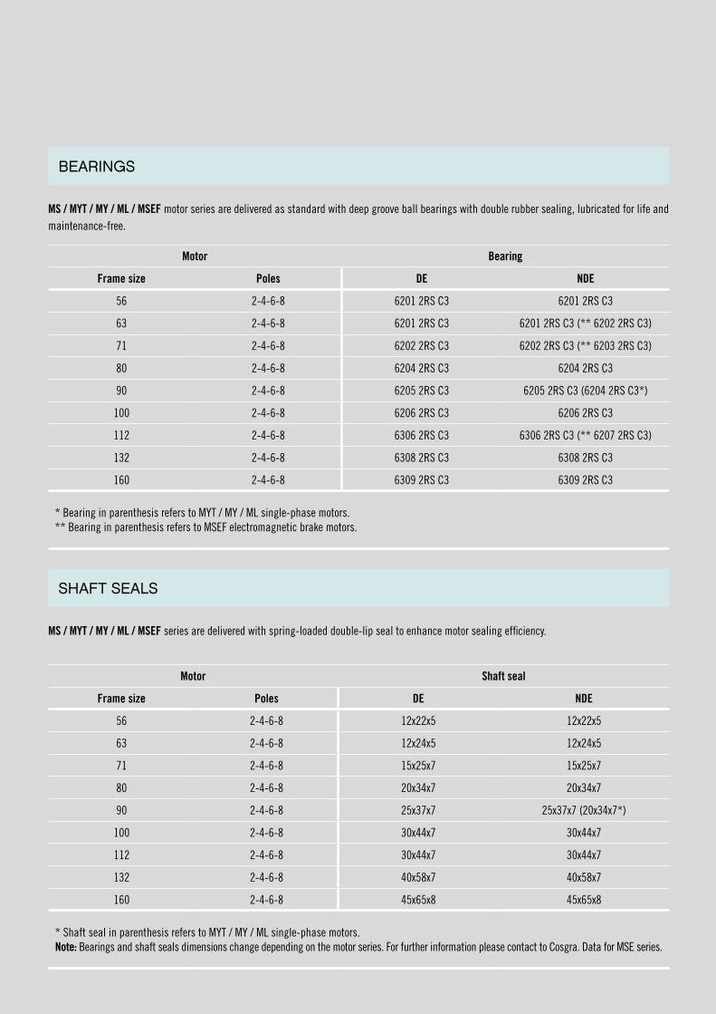
MS / MYT / MY / ML / MSEF motor series are delivered as standard with deep groove ball bearings with double rubber sealing, lubricated for life and maintenance-free.
MS / MYT / MY / ML / MSEF series are delivered with spring-loaded double-lip seal to enhance motor sealing efficiency.
BEARINGS
SHAFT SEALS
Motor Bearing
Frame size Poles DE NDE
56 2-4-6-8 6201 2RS C3 6201 2RS C3
63 2-4-6-8 6201 2RS C3 6201 2RS C3 (** 6202 2RS C3)
71 2-4-6-8 6202 2RS C3 6202 2RS C3 (** 6203 2RS C3)
80 2-4-6-8 6204 2RS C3 6204 2RS C3
90 2-4-6-8 6205 2RS C3 6205 2RS C3 (6204 2RS C3*)
100 2-4-6-8 6206 2RS C3 6206 2RS C3
112 2-4-6-8 6306 2RS C3 6306 2RS C3 (** 6207 2RS C3)
132 2-4-6-8 6308 2RS C3 6308 2RS C3
160 2-4-6-8 6309 2RS C3 6309 2RS C3
* Bearing in parenthesis refers to MYT / MY / ML single-phase motors.** Bearing in parenthesis refers to MSEF electromagnetic brake motors.
Motor Shaft seal
Frame size Poles DE NDE
56 2-4-6-8 12x22x5 12x22x5
63 2-4-6-8 12x24x5 12x24x5
71 2-4-6-8 15x25x7 15x25x7
80 2-4-6-8 20x34x7 20x34x7
90 2-4-6-8 25x37x7 25x37x7 (20x34x7*)
100 2-4-6-8 30x44x7 30x44x7
112 2-4-6-8 30x44x7 30x44x7
132 2-4-6-8 40x58x7 40x58x7
160 2-4-6-8 45x65x8 45x65x8
* Shaft seal in parenthesis refers to MYT / MY / ML single-phase motors.Note: Bearings and shaft seals dimensions change depending on the motor series. For further information please contact to Cosgra. Data for MSE series.
12
EGMOTORSERIES
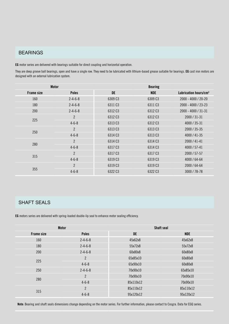
EG motor series are delivered with bearings suitable for direct coupling and horizontal operation.
They are deep groove ball bearings, open and have a single row. They need to be lubricated with lithium-based grease suitable for bearings. EG cast iron motors are designed with an external lubrication system.
EG motors series are delivered with spring-loaded double-lip seal to enhance motor sealing efficiency.
BEARINGS
SHAFT SEALS
Motor Bearing
Frame size Poles DE NDE Lubrication hours/cm3
160 2-4-6-8 6309 C3 6309 C3 2000 - 4000 / 20-20
180 2-4-6-8 6311 C3 6311 C3 2000 - 4000 / 23-23
200 2-4-6-8 6312 C3 6312 C3 2000 - 4000 / 31-31
2252 6312 C3 6312 C3 2000 / 31-31
4-6-8 6313 C3 6312 C3 4000 / 35-31
2502 6313 C3 6313 C3 2000 / 35-35
4-6-8 6314 C3 6313 C3 4000 / 41-35
2802 6314 C3 6314 C3 2000 / 41-41
4-6-8 6317 C3 6314 C3 4000 / 57-41
3152 6317 C3 6317 C3 2000 / 57-57
4-6-8 6319 C3 6319 C3 4000 / 64-64
3552 6319 C3 6319 C3 2000 / 64-64
4-6-8 6322 C3 6322 C3 3000 / 78-78
Motor Shaft seal
Frame size Poles DE NDE
160 2-4-6-8 45x62x8 45x62x8
180 2-4-6-8 55x72x8 55x72x8
200 2-4-6-8 60x80x8 60x80x8
2252 65x85x10 60x80x8
4-6-8 65x90x10 60x80x8
250 2-4-6-8 70x90x10 65x85x10
2802 70x90x10 70x90x10
4-6-8 85x110x12 70x90x10
3152 85x110x12 85x110x12
4-6-8 95x120x12 95x120x12
Note: Bearing and shaft seals dimensions change depending on the motor series. For further information, please contact to Cosgra. Data for EGQ series.
14
Transmission elements need to be selected carefully in order to ensure a good performance of the motor. Please contact your supplier of belts, pulleys and couplings or our technical department.
When a motor is driven by belt/pulley, there’s a high radial force on the motor’s shaft, which is transmitted to the DE bearing. For motors from frame size IEC-56 to 250 (included) the magnitude of this force is not important and it can be used a standard bearing.
Motors from frame size IEC-160 to 355 need a cylindrical roller bearing (NU-type), which is selected depending on the application. Following information about pulley will be required:
-Weight (Kg) -Outer diameter (mm)
-Number of grooves (N) -Width (mm)
IMPORTANT. Cylindrical roller bearings (NU) must always support at least 25% of their maximum radial load in order to ensure their correct operation. In many cases, the weight of the element supported by the bearing, together with the external forces, is greater than the minimum required load.
Mounting positions: B3-V6, B35-V36, B34-IM 2131, B5-V3 and B14-V19 (see page 9).
Motors are designed to work horizontally, and when they work vertically –shaft up-, the DE bearing (the one in upper position) supports the shaft and rotor weight, which means a higher axial force than estimated.
For motors from frame size IEC-56 to 250 (included) the magnitude of this force is not important and it can be used a standard bearing.
For motors of frame size IEC-280, 315 and 355 an angular contact ball bearing (QJ /7000 type) must be installed at DE.
Mounting positions: B3-V5, B35-V15, B34-IM 2111, B5-V1 and B14-V18 (see page 9).
Motors are designed to work horizontally, and when they work vertically -shaft down-, the NDE bearing (the one in upper position) supports the shaft and rotor weight, which means a higher axial force than estimated.
For motors from frame size IEC-56 to 250 (included) the magnitude of this force is not important and it can be used a standard bearing.
For motors of frame size IEC-280, 315 and 355 an angular contact ball bearing (QJ/7000 type) must be installed at NDE.
(*) This information is not binding. Please contact to Cosgra to study your application.
VERTICALLY MOUNTED MOTORS – SHAFT UP (*)
VERTICALLY MOUNTED MOTORS – SHAFT DOWN (*)
MOTORS MODIFICATIONS
BELT/PULLEY TRANSMISSION (*)
On request, motors with following protection systems can be supplied:
• PTC thermistors in the winding (on request; from frame size 160 included).
• Temperature bimetallic thermistors (klixon), normally closed NC or normally open NO.
• PT100 thermistors in bearings and winding.
• Anti-condensation heaters in winding.
All CEMER motors can be powered by a frequency converter, but always bearing in mind the following technical requirements.
If the customer does not take precautions in the design of the electrical system, motors manufactured with standard insulation can fail and break down. Voltage peaks on the motor’s terminals can have very great amplitude and last for a long time. Depending on the type, length and configuration of the motor’s cabling, impulses can as much as double the voltage of the frequency changer link.
If the exchanger link voltage does not exceed 600 V, CEMER motors can operate with a frequency changer with output voltage up to 420 V without any kind of subsequent filter. It is recommended to order motors, if possible, with a star (Y) connection.
COSGRA recommends motors with an insulated protection system from frame size 280 (included) to avoid damages of residual currents.
Motors are just one complex part of an electrical drive system. Nowadays the frequency changer protects itself and the motor against thermal overload, but it will not detect the excess voltage peaks on the motor terminals. For the drive system, the problems can increase in the absence of frequency changer output filters and/or with excessively long cables. This often causes serious damage to the motor insulation.
There are various options for optimising the electrical drive system:
- Frequency changer output filter circuits (choke, du/dt, sine).
- Motor with reinforced insulation system.
- Combination of both the above.
The person responsible for the study must carefully select the different components of the system. That person is responsible for ensuring the voltage in the motor terminals does not exceed the permitted values. This also includes selecting the motor insulation system, always bearing in mind the effects of the other components of the whole.
To compensate for loss of performance of the motor due to the frequency converter, it is appropriate to use a service factor of 1.1 or above.
It is highly recommended to install temperature thermistors in the winding to prevent the motor overheating.
Sometimes forced ventilation is needed. See pages 45 and 46.
We have a technical department specialising in this kind of application who can advise you on selecting the motor correctly, depending on the application.
(**) Non-binding information. Please contact to Cosgra to study your application.
S9 DUTY FREQUENCY CONVERTER OPERATION MOTORS (**)
PROTECTION SYSTEMS
16
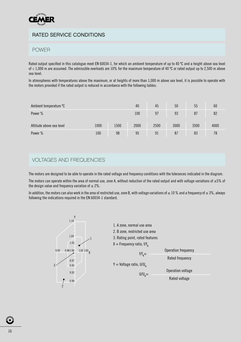
Rated output specified in this catalogue meet EN 60034-1, for which an ambient temperature of up to 40 ºC and a height above sea level of ≤ 1,000 m are assumed. The admissible overloads are 10% for the maximum temperature of 40 ºC or rated output up to 2,500 m above sea level.
In atmospheres with temperatures above the maximum, or at heights of more than 1,000 m above sea level, it is possible to operate with the motors provided if the rated output is reduced in accordance with the following tables:
The motors are designed to be able to operate in the rated voltage and frequency conditions with the tolerances indicated in the diagram.
The motors can operate within the area of normal use, zone A, without reduction of the rated output and with voltage variations of ±5% of the design value and frequency variation of ± 2%.
In addition, the motors can also work in the area of restricted use, zone B, with voltage variations of ± 10 % and a frequency of ± 3%, always following the indications required in the EN 60034-1 standard.
Y
X
1.10
1.05
1.03
0.97
0.95
0.93
0.90
0.95 0.981.00 1.02 1.03
1
2
3
1. A zone, normal use area
2. B zone, restricted use area
3. Rating point, rated features
X = Frequency ratio, f/fN
Operation frequency f/fN= Rated frequency
Y = Voltage ratio, U/UN
Operation voltage U/UN= Rated voltage
RATED SERVICE CONDITIONS
Ambient temperature ºC 40 45 50 55 60
Power % 100 97 93 87 82
Altitude above sea level 1000 1500 2000 2500 3000 3500 4000
Power % 100 98 95 91 87 83 78
POWER
VOLTAGES AND FREQUENCIES
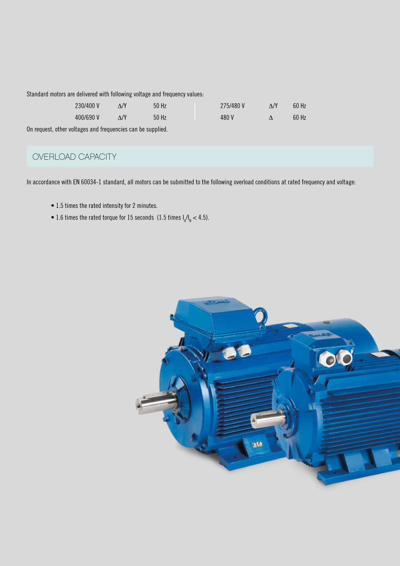
In accordance with EN 60034-1 standard, all motors can be submitted to the following overload conditions at rated frequency and voltage:
• 1.5 times the rated intensity for 2 minutes.
• 1.6 times the rated torque for 15 seconds (1.5 times IA/IN < 4.5).
Standard motors are delivered with following voltage and frequency values:
230/400 V Δ/Y 50 Hz 275/480 V Δ/Y 60 Hz
400/690 V Δ/Y 50 Hz 480 V Δ 60 Hz
On request, other voltages and frequencies can be supplied.
OVERLOAD CAPACITY
18
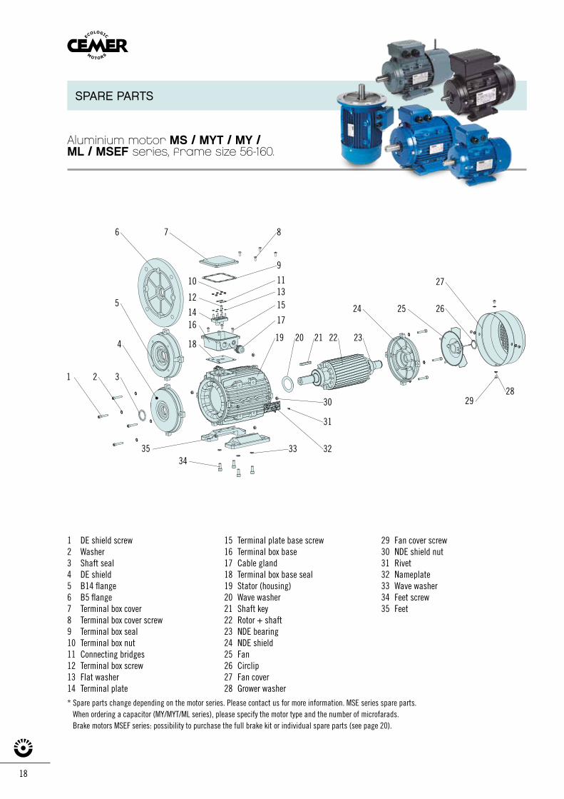
SPARE PARTS
1 DE shield screw2 Washer3 Shaft seal4 DE shield5 B14 flange6 B5 flange7 Terminal box cover8 Terminal box cover screw9 Terminal box seal10 Terminal box nut 11 Connecting bridges12 Terminal box screw13 Flat washer14 Terminal plate
15 Terminal plate base screw16 Terminal box base17 Cable gland18 Terminal box base seal19 Stator (housing)20 Wave washer21 Shaft key22 Rotor + shaft23 NDE bearing24 NDE shield25 Fan26 Circlip27 Fan cover28 Grower washer
29 Fan cover screw30 NDE shield nut 31 Rivet32 Nameplate33 Wave washer34 Feet screw35 Feet
* Spare parts change depending on the motor series. Please contact us for more information. MSE series spare parts. When ordering a capacitor (MY/MYT/ML series), please specify the motor type and the number of microfarads. Brake motors MSEF series: possibility to purchase the full brake kit or individual spare parts (see page 20).
1 2 3
4
5
6 7 8
9
1110
12
1416
18
1315
17
19 20 21 22 23
24 25 26
27
282930
31
323334
35
Aluminium motor MS / MYT / MY /ML / MSEF series, frame size 56-160.
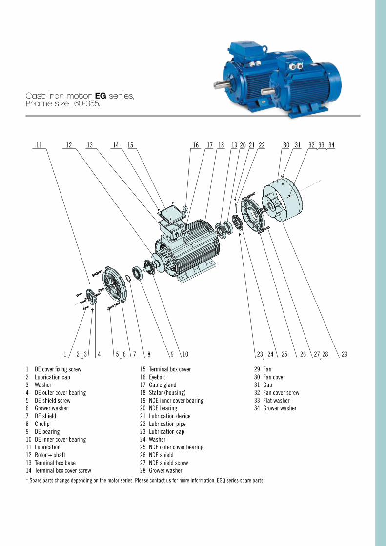
1 DE cover fixing screw 2 Lubrication cap3 Washer4 DE outer cover bearing5 DE shield screw6 Grower washer7 DE shield8 Circlip9 DE bearing10 DE inner cover bearing 11 Lubrication12 Rotor + shaft13 Terminal box base14 Terminal box cover screw
15 Terminal box cover16 Eyebolt17 Cable gland18 Stator (housing)19 NDE inner cover bearing 20 NDE bearing21 Lubrication device22 Lubrication pipe23 Lubrication cap 24 Washer25 NDE outer cover bearing26 NDE shield27 NDE shield screw28 Grower washer
29 Fan30 Fan cover31 Cap32 Fan cover screw33 Flat washer34 Grower washer
* Spare parts change depending on the motor series. Please contact us for more information. EGQ series spare parts.
11 12 13 14 15 16 17 18 19 20 21 22 30 31 32 33 34
2928272625242310987654321
Cast iron motor EG series,frame size 160-355.

20
øE
1
2
5
6
4
8
9
7
3
øC I
øD
L O
øG
MNP
P
øD
øBøA
øCøEøF
OM N
øHøG
L
9
7
3
1
2
5
6
4
8
øE
1
2
5
6
4
8
9
7
3
øC I
øD
L O
øG
MNP
P
øD
øBøA
øCøEøF
OM N
øHøG
L
9
7
3
1
2
5
6
4
8
BRAKE SYSTEM
Brake system spare parts
Electromagnetic brake motors,MSEFA / MSEFC series, frame size 63-160.
MSEFA seriesAC brake system(Connection 230/400V 50Hz III)
1 Electromagnet
2 Armature plate
3 Adjusting screw
4 Torque spring
5 Brake hub
6 Brake disc
7 O-ring
8 Brake torque adjusting screw
9 Fixing screws
MSEFC seriesDC brake system(Single-phase connection 230V through rectifier 110V DC)
1 Electromagnet
2 Armature plate
3 Torque spring
4 Brake disc
5 Brake hub
6 O-ring
7 Adjusting ring
8 Adjusting nut
9 Fixing screws
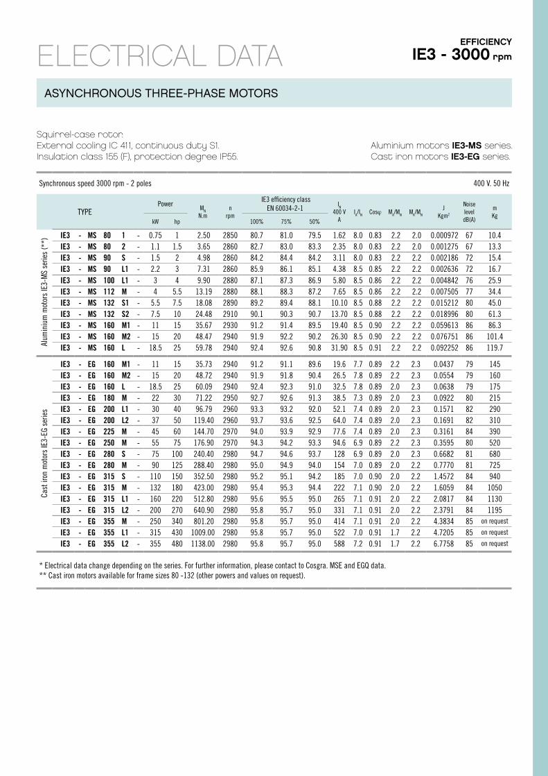
Squirrel-case rotor.External cooling IC 411, continuous duty S1.Insulation class 155 (F), protection degree IP55.
Aluminium motors IE3-MS series. Cast iron motors IE3-EG series.
Synchronous speed 3000 rpm - 2 poles 400 V. 50 Hz
TYPEPower
MN
N.mn
rpm
IE3 efficiency classEN 60034-2-1
IN
400 VA
IA/IN Cosϕ MA/MN MK/MN
JKgm2
Noise leveldB(A)
mKg
kW hp 100% 75% 50%
IE3 - MS 80 1 - 0.75 1 2.50 2850 80.7 81.0 79.5 1.62 8.0 0.83 2.2 2.0 0.000972 67 10.4 IE3 - MS 80 2 - 1.1 1.5 3.65 2860 82.7 83.0 83.3 2.35 8.0 0.83 2.2 2.0 0.001275 67 13.3 IE3 - MS 90 S - 1.5 2 4.98 2860 84.2 84.4 84.2 3.11 8.0 0.83 2.2 2.2 0.002186 72 15.4 IE3 - MS 90 L1 - 2.2 3 7.31 2860 85.9 86.1 85.1 4.38 8.5 0.85 2.2 2.2 0.002636 72 16.7 IE3 - MS 100 L1 - 3 4 9.90 2880 87.1 87.3 86.9 5.80 8.5 0.86 2.2 2.2 0.004842 76 25.9 IE3 - MS 112 M - 4 5.5 13.19 2880 88.1 88.3 87.2 7.65 8.5 0.86 2.2 2.2 0.007505 77 34.4 IE3 - MS 132 S1 - 5.5 7.5 18.08 2890 89.2 89.4 88.1 10.10 8.5 0.88 2.2 2.2 0.015212 80 45.0 IE3 - MS 132 S2 - 7.5 10 24.48 2910 90.1 90.3 90.7 13.70 8.5 0.88 2.2 2.2 0.018996 80 61.3 IE3 - MS 160 M1 - 11 15 35.67 2930 91.2 91.4 89.5 19.40 8.5 0.90 2.2 2.2 0.059613 86 86.3 IE3 - MS 160 M2 - 15 20 48.47 2940 91.9 92.2 90.2 26.30 8.5 0.90 2.2 2.2 0.076751 86 101.4 IE3 - MS 160 L - 18.5 25 59.78 2940 92.4 92.6 90.8 31.90 8.5 0.91 2.2 2.2 0.092252 86 119.7
IE3 - EG 160 M1 - 11 15 35.73 2940 91.2 91.1 89.6 19.6 7.7 0.89 2.2 2.3 0.0437 79 145 IE3 - EG 160 M2 - 15 20 48.72 2940 91.9 91.8 90.4 26.5 7.8 0.89 2.2 2.3 0.0554 79 160 IE3 - EG 160 L - 18.5 25 60.09 2940 92.4 92.3 91.0 32.5 7.8 0.89 2.0 2.3 0.0638 79 175 IE3 - EG 180 M - 22 30 71.22 2950 92.7 92.6 91.3 38.5 7.3 0.89 2.0 2.3 0.0922 80 215 IE3 - EG 200 L1 - 30 40 96.79 2960 93.3 93.2 92.0 52.1 7.4 0.89 2.0 2.3 0.1571 82 290 IE3 - EG 200 L2 - 37 50 119.40 2960 93.7 93.6 92.5 64.0 7.4 0.89 2.0 2.3 0.1691 82 310 IE3 - EG 225 M - 45 60 144.70 2970 94.0 93.9 92.9 77.6 7.4 0.89 2.0 2.3 0.3161 84 390 IE3 - EG 250 M - 55 75 176.90 2970 94.3 94.2 93.3 94.6 6.9 0.89 2.2 2.3 0.3595 80 520 IE3 - EG 280 S - 75 100 240.40 2980 94.7 94.6 93.7 128 6.9 0.89 2.0 2.3 0.6682 81 680 IE3 - EG 280 M - 90 125 288.40 2980 95.0 94.9 94.0 154 7.0 0.89 2.0 2.2 0.7770 81 725 IE3 - EG 315 S - 110 150 352.50 2980 95.2 95.1 94.2 185 7.0 0.90 2.0 2.2 1.4572 84 940 IE3 - EG 315 M - 132 180 423.00 2980 95.4 95.3 94.4 222 7.1 0.90 2.0 2.2 1.6059 84 1050 IE3 - EG 315 L1 - 160 220 512.80 2980 95.6 95.5 95.0 265 7.1 0.91 2.0 2.2 2.0817 84 1130 IE3 - EG 315 L2 - 200 270 640.90 2980 95.8 95.7 95.0 331 7.1 0.91 2.0 2.2 2.3791 84 1195 IE3 - EG 355 M - 250 340 801.20 2980 95.8 95.7 95.0 414 7.1 0.91 2.0 2.2 4.3834 85 on request
IE3 - EG 355 L1 - 315 430 1009.00 2980 95.8 95.7 95.0 522 7.0 0.91 1.7 2.2 4.7205 85 on request
IE3 - EG 355 L2 - 355 480 1138.00 2980 95.8 95.7 95.0 588 7.2 0.91 1.7 2.2 6.7758 85 on request
* Electrical data change depending on the series. For further information, please contact to Cosgra. MSE and EGQ data.** Cast iron motors available for frame sizes 80 -132 (other powers and values on request).
Cast
iron
mot
ors
IE3-
EG s
erie
sAl
umin
ium
mot
ors
IE3-
MS
serie
s (*
*)EFFICIENCY
IE3 - 3000 rpm
ASYNCHRONOUS THREE-PHASE MOTORS
ELECTRICAL DATA
22
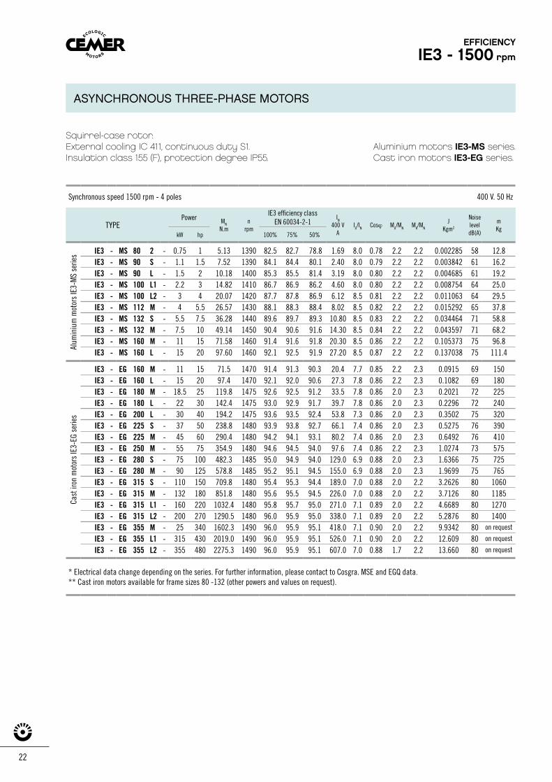
Squirrel-case rotor.External cooling IC 411, continuous duty S1.Insulation class 155 (F), protection degree IP55.
Aluminium motors IE3-MS series.Cast iron motors IE3-EG series.
Synchronous speed 1500 rpm - 4 poles 400 V. 50 Hz
TYPEPower MN
N.mn
rpm
IE3 efficiency classEN 60034-2-1
IN
400 VA
IA/IN Cosϕ MA/MN MK/MN
JKgm2
NoiseleveldB(A)
mKg
kW hp 100% 75% 50%
IE3 - MS 80 2 - 0.75 1 5.13 1390 82.5 82.7 78.8 1.69 8.0 0.78 2.2 2.2 0.002285 58 12.8IE3 - MS 90 S - 1.1 1.5 7.52 1390 84.1 84.4 80.1 2.40 8.0 0.79 2.2 2.2 0.003842 61 16.2IE3 - MS 90 L - 1.5 2 10.18 1400 85.3 85.5 81.4 3.19 8.0 0.80 2.2 2.2 0.004685 61 19.2IE3 - MS 100 L1 - 2.2 3 14.82 1410 86.7 86.9 86.2 4.60 8.0 0.80 2.2 2.2 0.008754 64 25.0IE3 - MS 100 L2 - 3 4 20.07 1420 87.7 87.8 86.9 6.12 8.5 0.81 2.2 2.2 0.011063 64 29.5IE3 - MS 112 M - 4 5.5 26.57 1430 88.1 88.3 88.4 8.02 8.5 0.82 2.2 2.2 0.015292 65 37.8IE3 - MS 132 S - 5.5 7.5 36.28 1440 89.6 89.7 89.3 10.80 8.5 0.83 2.2 2.2 0.034464 71 58.8IE3 - MS 132 M - 7.5 10 49.14 1450 90.4 90.6 91.6 14.30 8.5 0.84 2.2 2.2 0.043597 71 68.2IE3 - MS 160 M - 11 15 71.58 1460 91.4 91.6 91.8 20.30 8.5 0.86 2.2 2.2 0.105373 75 96.8IE3 - MS 160 L - 15 20 97.60 1460 92.1 92.5 91.9 27.20 8.5 0.87 2.2 2.2 0.137038 75 111.4
IE3 - EG 160 M - 11 15 71.5 1470 91.4 91.3 90.3 20.4 7.7 0.85 2.2 2.3 0.0915 69 150IE3 - EG 160 L - 15 20 97.4 1470 92.1 92.0 90.6 27.3 7.8 0.86 2.2 2.3 0.1082 69 180IE3 - EG 180 M - 18.5 25 119.8 1475 92.6 92.5 91.2 33.5 7.8 0.86 2.0 2.3 0.2021 72 225IE3 - EG 180 L - 22 30 142.4 1475 93.0 92.9 91.7 39.7 7.8 0.86 2.0 2.3 0.2296 72 240IE3 - EG 200 L - 30 40 194.2 1475 93.6 93.5 92.4 53.8 7.3 0.86 2.0 2.3 0.3502 75 320IE3 - EG 225 S - 37 50 238.8 1480 93.9 93.8 92.7 66.1 7.4 0.86 2.0 2.3 0.5275 76 390IE3 - EG 225 M - 45 60 290.4 1480 94.2 94.1 93.1 80.2 7.4 0.86 2.0 2.3 0.6492 76 410IE3 - EG 250 M - 55 75 354.9 1480 94.6 94.5 94.0 97.6 7.4 0.86 2.2 2.3 1.0274 73 575IE3 - EG 280 S - 75 100 482.3 1485 95.0 94.9 94.0 129.0 6.9 0.88 2.0 2.3 1.6366 75 725IE3 - EG 280 M - 90 125 578.8 1485 95.2 95.1 94.5 155.0 6.9 0.88 2.0 2.3 1.9699 75 765IE3 - EG 315 S - 110 150 709.8 1480 95.4 95.3 94.4 189.0 7.0 0.88 2.0 2.2 3.2626 80 1060IE3 - EG 315 M - 132 180 851.8 1480 95.6 95.5 94.5 226.0 7.0 0.88 2.0 2.2 3.7126 80 1185IE3 - EG 315 L1 - 160 220 1032.4 1480 95.8 95.7 95.0 271.0 7.1 0.89 2.0 2.2 4.6689 80 1270IE3 - EG 315 L2 - 200 270 1290.5 1480 96.0 95.9 95.0 338.0 7.1 0.89 2.0 2.2 5.2876 80 1400IE3 - EG 355 M - 25 340 1602.3 1490 96.0 95.9 95.1 418.0 7.1 0.90 2.0 2.2 9.9342 80 on request
IE3 - EG 355 L1 - 315 430 2019.0 1490 96.0 95.9 95.1 526.0 7.1 0.90 2.0 2.2 12.609 80 on request
IE3 - EG 355 L2 - 355 480 2275.3 1490 96.0 95.9 95.1 607.0 7.0 0.88 1.7 2.2 13.660 80 on request
* Electrical data change depending on the series. For further information, please contact to Cosgra. MSE and EGQ data.** Cast iron motors available for frame sizes 80 -132 (other powers and values on request).
Cast
iron
mot
ors
IE3-
EG s
erie
sAl
umin
ium
mot
ors
IE3-
MS
serie
s
EFFICIENCY
IE3 - 1500 rpm
ASYNCHRONOUS THREE-PHASE MOTORS
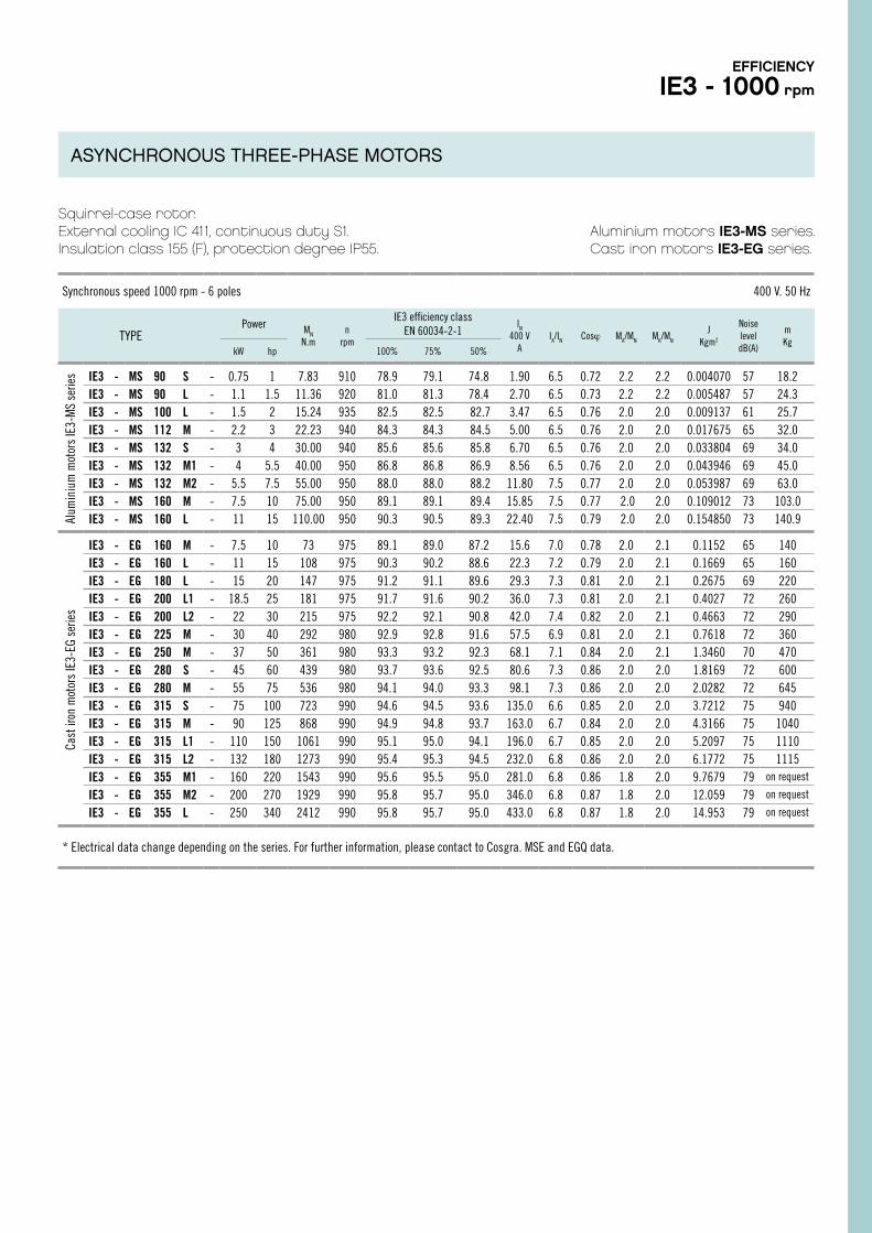
Squirrel-case rotor.External cooling IC 411, continuous duty S1.Insulation class 155 (F), protection degree IP55.
Aluminium motors IE3-MS series.Cast iron motors IE3-EG series.
Synchronous speed 1000 rpm - 6 poles 400 V. 50 Hz
TYPEPower MN
N.mn
rpm
IE3 efficiency classEN 60034-2-1
IN
400 VA
IA/IN Cosϕ MA/MN MK/MN
JKgm2
Noise level dB(A)
mKg
kW hp 100% 75% 50%
IE3 - MS 90 S - 0.75 1 7.83 910 78.9 79.1 74.8 1.90 6.5 0.72 2.2 2.2 0.004070 57 18.2IE3 - MS 90 L - 1.1 1.5 11.36 920 81.0 81.3 78.4 2.70 6.5 0.73 2.2 2.2 0.005487 57 24.3IE3 - MS 100 L - 1.5 2 15.24 935 82.5 82.5 82.7 3.47 6.5 0.76 2.0 2.0 0.009137 61 25.7IE3 - MS 112 M - 2.2 3 22.23 940 84.3 84.3 84.5 5.00 6.5 0.76 2.0 2.0 0.017675 65 32.0IE3 - MS 132 S - 3 4 30.00 940 85.6 85.6 85.8 6.70 6.5 0.76 2.0 2.0 0.033804 69 34.0IE3 - MS 132 M1 - 4 5.5 40.00 950 86.8 86.8 86.9 8.56 6.5 0.76 2.0 2.0 0.043946 69 45.0IE3 - MS 132 M2 - 5.5 7.5 55.00 950 88.0 88.0 88.2 11.80 7.5 0.77 2.0 2.0 0.053987 69 63.0IE3 - MS 160 M - 7.5 10 75.00 950 89.1 89.1 89.4 15.85 7.5 0.77 2.0 2.0 0.109012 73 103.0IE3 - MS 160 L - 11 15 110.00 950 90.3 90.5 89.3 22.40 7.5 0.79 2.0 2.0 0.154850 73 140.9
IE3 - EG 160 M - 7.5 10 73 975 89.1 89.0 87.2 15.6 7.0 0.78 2.0 2.1 0.1152 65 140IE3 - EG 160 L - 11 15 108 975 90.3 90.2 88.6 22.3 7.2 0.79 2.0 2.1 0.1669 65 160IE3 - EG 180 L - 15 20 147 975 91.2 91.1 89.6 29.3 7.3 0.81 2.0 2.1 0.2675 69 220IE3 - EG 200 L1 - 18.5 25 181 975 91.7 91.6 90.2 36.0 7.3 0.81 2.0 2.1 0.4027 72 260IE3 - EG 200 L2 - 22 30 215 975 92.2 92.1 90.8 42.0 7.4 0.82 2.0 2.1 0.4663 72 290IE3 - EG 225 M - 30 40 292 980 92.9 92.8 91.6 57.5 6.9 0.81 2.0 2.1 0.7618 72 360IE3 - EG 250 M - 37 50 361 980 93.3 93.2 92.3 68.1 7.1 0.84 2.0 2.1 1.3460 70 470IE3 - EG 280 S - 45 60 439 980 93.7 93.6 92.5 80.6 7.3 0.86 2.0 2.0 1.8169 72 600IE3 - EG 280 M - 55 75 536 980 94.1 94.0 93.3 98.1 7.3 0.86 2.0 2.0 2.0282 72 645IE3 - EG 315 S - 75 100 723 990 94.6 94.5 93.6 135.0 6.6 0.85 2.0 2.0 3.7212 75 940IE3 - EG 315 M - 90 125 868 990 94.9 94.8 93.7 163.0 6.7 0.84 2.0 2.0 4.3166 75 1040IE3 - EG 315 L1 - 110 150 1061 990 95.1 95.0 94.1 196.0 6.7 0.85 2.0 2.0 5.2097 75 1110IE3 - EG 315 L2 - 132 180 1273 990 95.4 95.3 94.5 232.0 6.8 0.86 2.0 2.0 6.1772 75 1115IE3 - EG 355 M1 - 160 220 1543 990 95.6 95.5 95.0 281.0 6.8 0.86 1.8 2.0 9.7679 79 on request
IE3 - EG 355 M2 - 200 270 1929 990 95.8 95.7 95.0 346.0 6.8 0.87 1.8 2.0 12.059 79 on request
IE3 - EG 355 L - 250 340 2412 990 95.8 95.7 95.0 433.0 6.8 0.87 1.8 2.0 14.953 79 on request
* Electrical data change depending on the series. For further information, please contact to Cosgra. MSE and EGQ data.
Cast
iron
mot
ors
IE3-
EG s
erie
sAl
umin
ium
mot
ors
IE3-
MS
serie
sEFFICIENCY
IE3 - 1000 rpm
ASYNCHRONOUS THREE-PHASE MOTORS
24
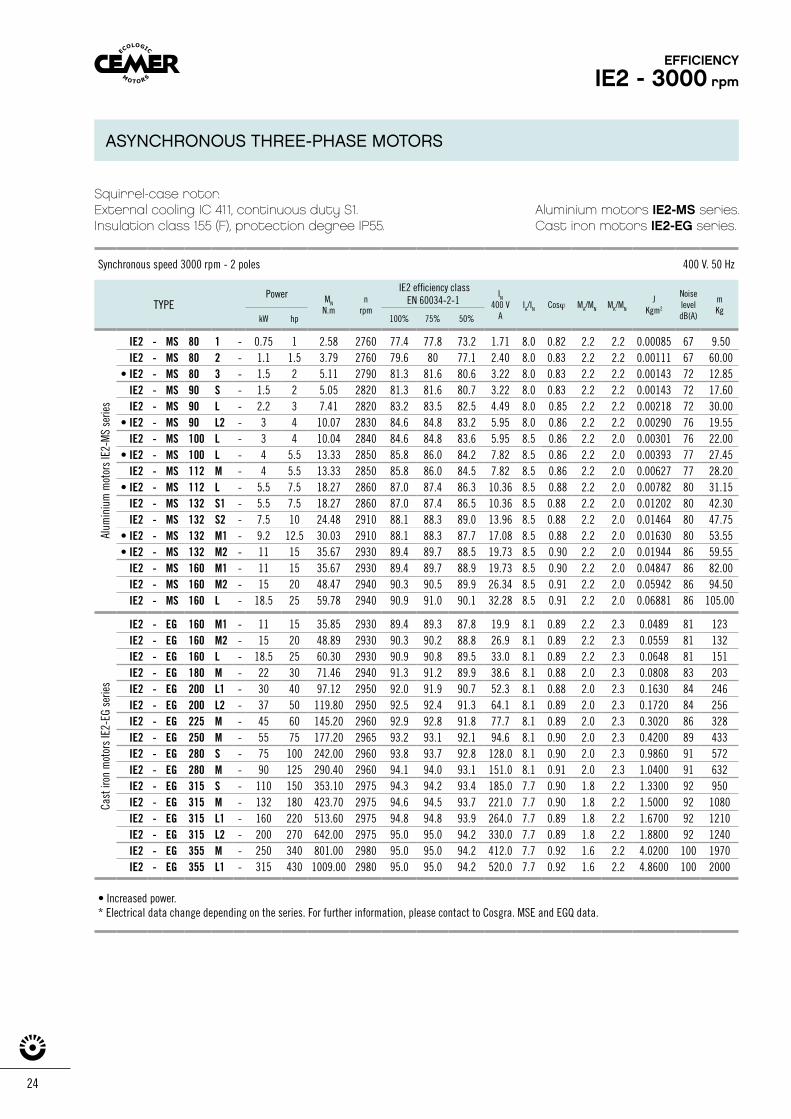
Squirrel-case rotor.External cooling IC 411, continuous duty S1.Insulation class 155 (F), protection degree IP55.
Aluminium motors IE2-MS series.Cast iron motors IE2-EG series.
Synchronous speed 3000 rpm - 2 poles 400 V. 50 Hz
TYPEPower MN
N.mn
rpm
IE2 efficiency classEN 60034-2-1
IN
400 VA
IA/IN Cosϕ MA/MN MK/MN
JKgm2
Noise leveldB(A)
mKg
kW hp 100% 75% 50%
IE2 - MS 80 1 - 0.75 1 2.58 2760 77.4 77.8 73.2 1.71 8.0 0.82 2.2 2.2 0.00085 67 9.50 IE2 - MS 80 2 - 1.1 1.5 3.79 2760 79.6 80 77.1 2.40 8.0 0.83 2.2 2.2 0.00111 67 60.00
• IE2 - MS 80 3 - 1.5 2 5.11 2790 81.3 81.6 80.6 3.22 8.0 0.83 2.2 2.2 0.00143 72 12.85 IE2 - MS 90 S - 1.5 2 5.05 2820 81.3 81.6 80.7 3.22 8.0 0.83 2.2 2.2 0.00143 72 17.60 IE2 - MS 90 L - 2.2 3 7.41 2820 83.2 83.5 82.5 4.49 8.0 0.85 2.2 2.2 0.00218 72 30.00
• IE2 - MS 90 L2 - 3 4 10.07 2830 84.6 84.8 83.2 5.95 8.0 0.86 2.2 2.2 0.00290 76 19.55 IE2 - MS 100 L - 3 4 10.04 2840 84.6 84.8 83.6 5.95 8.5 0.86 2.2 2.0 0.00301 76 22.00
• IE2 - MS 100 L - 4 5.5 13.33 2850 85.8 86.0 84.2 7.82 8.5 0.86 2.2 2.0 0.00393 77 27.45 IE2 - MS 112 M - 4 5.5 13.33 2850 85.8 86.0 84.5 7.82 8.5 0.86 2.2 2.0 0.00627 77 28.20
• IE2 - MS 112 L - 5.5 7.5 18.27 2860 87.0 87.4 86.3 10.36 8.5 0.88 2.2 2.0 0.00782 80 31.15 IE2 - MS 132 S1 - 5.5 7.5 18.27 2860 87.0 87.4 86.5 10.36 8.5 0.88 2.2 2.0 0.01202 80 42.30 IE2 - MS 132 S2 - 7.5 10 24.48 2910 88.1 88.3 89.0 13.96 8.5 0.88 2.2 2.0 0.01464 80 47.75
• IE2 - MS 132 M1 - 9.2 12.5 30.03 2910 88.1 88.3 87.7 17.08 8.5 0.88 2.2 2.0 0.01630 80 53.55 • IE2 - MS 132 M2 - 11 15 35.67 2930 89.4 89.7 88.5 19.73 8.5 0.90 2.2 2.0 0.01944 86 59.55
IE2 - MS 160 M1 - 11 15 35.67 2930 89.4 89.7 88.9 19.73 8.5 0.90 2.2 2.0 0.04847 86 82.00 IE2 - MS 160 M2 - 15 20 48.47 2940 90.3 90.5 89.9 26.34 8.5 0.91 2.2 2.0 0.05942 86 94.50 IE2 - MS 160 L - 18.5 25 59.78 2940 90.9 91.0 90.1 32.28 8.5 0.91 2.2 2.0 0.06881 86 105.00
IE2 - EG 160 M1 - 11 15 35.85 2930 89.4 89.3 87.8 19.9 8.1 0.89 2.2 2.3 0.0489 81 123IE2 - EG 160 M2 - 15 20 48.89 2930 90.3 90.2 88.8 26.9 8.1 0.89 2.2 2.3 0.0559 81 132IE2 - EG 160 L - 18.5 25 60.30 2930 90.9 90.8 89.5 33.0 8.1 0.89 2.2 2.3 0.0648 81 151IE2 - EG 180 M - 22 30 71.46 2940 91.3 91.2 89.9 38.6 8.1 0.88 2.0 2.3 0.0808 83 203IE2 - EG 200 L1 - 30 40 97.12 2950 92.0 91.9 90.7 52.3 8.1 0.88 2.0 2.3 0.1630 84 246IE2 - EG 200 L2 - 37 50 119.80 2950 92.5 92.4 91.3 64.1 8.1 0.89 2.0 2.3 0.1720 84 256IE2 - EG 225 M - 45 60 145.20 2960 92.9 92.8 91.8 77.7 8.1 0.89 2.0 2.3 0.3020 86 328IE2 - EG 250 M - 55 75 177.20 2965 93.2 93.1 92.1 94.6 8.1 0.90 2.0 2.3 0.4200 89 433IE2 - EG 280 S - 75 100 242.00 2960 93.8 93.7 92.8 128.0 8.1 0.90 2.0 2.3 0.9860 91 572IE2 - EG 280 M - 90 125 290.40 2960 94.1 94.0 93.1 151.0 8.1 0.91 2.0 2.3 1.0400 91 632IE2 - EG 315 S - 110 150 353.10 2975 94.3 94.2 93.4 185.0 7.7 0.90 1.8 2.2 1.3300 92 950IE2 - EG 315 M - 132 180 423.70 2975 94.6 94.5 93.7 221.0 7.7 0.90 1.8 2.2 1.5000 92 1080IE2 - EG 315 L1 - 160 220 513.60 2975 94.8 94.8 93.9 264.0 7.7 0.89 1.8 2.2 1.6700 92 1210IE2 - EG 315 L2 - 200 270 642.00 2975 95.0 95.0 94.2 330.0 7.7 0.89 1.8 2.2 1.8800 92 1240IE2 - EG 355 M - 250 340 801.00 2980 95.0 95.0 94.2 412.0 7.7 0.92 1.6 2.2 4.0200 100 1970IE2 - EG 355 L1 - 315 430 1009.00 2980 95.0 95.0 94.2 520.0 7.7 0.92 1.6 2.2 4.8600 100 2000
• Increased power.* Electrical data change depending on the series. For further information, please contact to Cosgra. MSE and EGQ data.
Cast
iron
mot
ors
IE2-
EG s
erie
sAl
umin
ium
mot
ors
IE2-
MS
serie
s
EFFICIENCY
IE2 - 3000 rpm
ASYNCHRONOUS THREE-PHASE MOTORS
Synchronous speed 3000 rpm - 2 poles 400 V. 50 Hz
TYPEPower MN
N.mn
rpm
IE2 efficiency classEN 60034-2-1
IN
400 VA
IA/IN Cosϕ MA/MN MK/MN
JKgm2
Noise leveldB(A)
mKg
kW hp 100% 75% 50%
IE2 - MS 80 1 - 0.75 1 2.58 2760 77.4 77.8 73.2 1.71 8.0 0.82 2.2 2.2 0.00085 67 9.50 IE2 - MS 80 2 - 1.1 1.5 3.79 2760 79.6 80 77.1 2.40 8.0 0.83 2.2 2.2 0.00111 67 60.00
• IE2 - MS 80 3 - 1.5 2 5.11 2790 81.3 81.6 80.6 3.22 8.0 0.83 2.2 2.2 0.00143 72 12.85 IE2 - MS 90 S - 1.5 2 5.05 2820 81.3 81.6 80.7 3.22 8.0 0.83 2.2 2.2 0.00143 72 17.60 IE2 - MS 90 L - 2.2 3 7.41 2820 83.2 83.5 82.5 4.49 8.0 0.85 2.2 2.2 0.00218 72 30.00
• IE2 - MS 90 L2 - 3 4 10.07 2830 84.6 84.8 83.2 5.95 8.0 0.86 2.2 2.2 0.00290 76 19.55 IE2 - MS 100 L - 3 4 10.04 2840 84.6 84.8 83.6 5.95 8.5 0.86 2.2 2.0 0.00301 76 22.00
• IE2 - MS 100 L - 4 5.5 13.33 2850 85.8 86.0 84.2 7.82 8.5 0.86 2.2 2.0 0.00393 77 27.45 IE2 - MS 112 M - 4 5.5 13.33 2850 85.8 86.0 84.5 7.82 8.5 0.86 2.2 2.0 0.00627 77 28.20
• IE2 - MS 112 L - 5.5 7.5 18.27 2860 87.0 87.4 86.3 10.36 8.5 0.88 2.2 2.0 0.00782 80 31.15 IE2 - MS 132 S1 - 5.5 7.5 18.27 2860 87.0 87.4 86.5 10.36 8.5 0.88 2.2 2.0 0.01202 80 42.30 IE2 - MS 132 S2 - 7.5 10 24.48 2910 88.1 88.3 89.0 13.96 8.5 0.88 2.2 2.0 0.01464 80 47.75
• IE2 - MS 132 M1 - 9.2 12.5 30.03 2910 88.1 88.3 87.7 17.08 8.5 0.88 2.2 2.0 0.01630 80 53.55 • IE2 - MS 132 M2 - 11 15 35.67 2930 89.4 89.7 88.5 19.73 8.5 0.90 2.2 2.0 0.01944 86 59.55
IE2 - MS 160 M1 - 11 15 35.67 2930 89.4 89.7 88.9 19.73 8.5 0.90 2.2 2.0 0.04847 86 82.00 IE2 - MS 160 M2 - 15 20 48.47 2940 90.3 90.5 89.9 26.34 8.5 0.91 2.2 2.0 0.05942 86 94.50 IE2 - MS 160 L - 18.5 25 59.78 2940 90.9 91.0 90.1 32.28 8.5 0.91 2.2 2.0 0.06881 86 105.00
IE2 - EG 160 M1 - 11 15 35.85 2930 89.4 89.3 87.8 19.9 8.1 0.89 2.2 2.3 0.0489 81 123IE2 - EG 160 M2 - 15 20 48.89 2930 90.3 90.2 88.8 26.9 8.1 0.89 2.2 2.3 0.0559 81 132IE2 - EG 160 L - 18.5 25 60.30 2930 90.9 90.8 89.5 33.0 8.1 0.89 2.2 2.3 0.0648 81 151IE2 - EG 180 M - 22 30 71.46 2940 91.3 91.2 89.9 38.6 8.1 0.88 2.0 2.3 0.0808 83 203IE2 - EG 200 L1 - 30 40 97.12 2950 92.0 91.9 90.7 52.3 8.1 0.88 2.0 2.3 0.1630 84 246IE2 - EG 200 L2 - 37 50 119.80 2950 92.5 92.4 91.3 64.1 8.1 0.89 2.0 2.3 0.1720 84 256IE2 - EG 225 M - 45 60 145.20 2960 92.9 92.8 91.8 77.7 8.1 0.89 2.0 2.3 0.3020 86 328IE2 - EG 250 M - 55 75 177.20 2965 93.2 93.1 92.1 94.6 8.1 0.90 2.0 2.3 0.4200 89 433IE2 - EG 280 S - 75 100 242.00 2960 93.8 93.7 92.8 128.0 8.1 0.90 2.0 2.3 0.9860 91 572IE2 - EG 280 M - 90 125 290.40 2960 94.1 94.0 93.1 151.0 8.1 0.91 2.0 2.3 1.0400 91 632IE2 - EG 315 S - 110 150 353.10 2975 94.3 94.2 93.4 185.0 7.7 0.90 1.8 2.2 1.3300 92 950IE2 - EG 315 M - 132 180 423.70 2975 94.6 94.5 93.7 221.0 7.7 0.90 1.8 2.2 1.5000 92 1080IE2 - EG 315 L1 - 160 220 513.60 2975 94.8 94.8 93.9 264.0 7.7 0.89 1.8 2.2 1.6700 92 1210IE2 - EG 315 L2 - 200 270 642.00 2975 95.0 95.0 94.2 330.0 7.7 0.89 1.8 2.2 1.8800 92 1240IE2 - EG 355 M - 250 340 801.00 2980 95.0 95.0 94.2 412.0 7.7 0.92 1.6 2.2 4.0200 100 1970IE2 - EG 355 L1 - 315 430 1009.00 2980 95.0 95.0 94.2 520.0 7.7 0.92 1.6 2.2 4.8600 100 2000
• Increased power.* Electrical data change depending on the series. For further information, please contact to Cosgra. MSE and EGQ data.
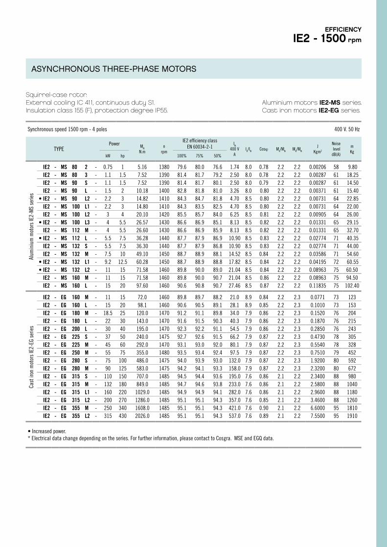
Squirrel-case rotor.External cooling IC 411, continuous duty S1.Insulation class 155 (F), protection degree IP55.
Aluminium motors IE2-MS series.Cast iron motors IE2-EG series.
Synchronous speed 1500 rpm - 4 poles 400 V. 50 Hz
TYPEPower MN
N.mn
rpm
IE2 efficiency classEN 60034-2-1
IN
400 VA
IA/IN Cosϕ MA/MN MK/MN
JKgm2
Noise leveldB(A)
mKg
kW hp 100% 75% 50%
IE2 - MS 80 2 - 0.75 1 5.16 1380 79.6 80.0 76.6 1.74 8.0 0.78 2.2 2.2 0.00206 58 9.80 IE2 - MS 80 3 - 1.1 1.5 7.52 1390 81.4 81.7 79.2 2.50 8.0 0.78 2.2 2.2 0.00287 61 18.25 IE2 - MS 90 S - 1.1 1.5 7.52 1390 81.4 81.7 80.1 2.50 8.0 0.79 2.2 2.2 0.00287 61 14.50 IE2 - MS 90 L - 1.5 2 10.18 1400 82.8 81.8 81.0 3.26 8.0 0.80 2.2 2.2 0.00371 61 15.40
• IE2 - MS 90 L2 - 2.2 3 14.82 1410 84.3 84.7 81.8 4.70 8.5 0.80 2.2 2.2 0.00731 64 22.85 IE2 - MS 100 L1 - 2.2 3 14.80 1410 84.3 83.5 82.5 4.70 8.5 0.80 2.2 2.2 0.00731 64 22.00 IE2 - MS 100 L2 - 3 4 20.10 1420 85.5 85.7 84.0 6.25 8.5 0.81 2.2 2.2 0.00905 64 26.00
• IE2 - MS 100 L3 - 4 5.5 26.57 1430 86.6 86.9 85.1 8.13 8.5 0.82 2.2 2.2 0.01331 65 29.15 IE2 - MS 112 M - 4 5.5 26.60 1430 86.6 86.9 85.9 8.13 8.5 0.82 2.2 2.2 0.01331 65 32.70
• IE2 - MS 112 L - 5.5 7.5 36.28 1440 87.7 87.9 86.9 10.90 8.5 0.83 2.2 2.2 0.02774 71 40.35 IE2 - MS 132 S - 5.5 7.5 36.30 1440 87.7 87.9 86.8 10.90 8.5 0.83 2.2 2.2 0.02774 71 44.00 IE2 - MS 132 M - 7.5 10 49.10 1450 88.7 88.9 88.1 14.52 8.5 0.84 2.2 2.2 0.03586 71 54.60
• IE2 - MS 132 L1 - 9.2 12.5 60.28 1450 88.7 88.9 88.8 17.82 8.5 0.84 2.2 2.2 0.04195 72 60.55 • IE2 - MS 132 L2 - 11 15 71.58 1460 89.8 90.0 89.0 21.04 8.5 0.84 2.2 2.2 0.08963 75 60.50
IE2 - MS 160 M - 11 15 71.58 1460 89.8 90.0 90.7 21.04 8.5 0.86 2.2 2.2 0.08963 75 94.50IE2 - MS 160 L - 15 20 97.60 1460 90.6 90.8 90.7 27.46 8.5 0.87 2.2 2.2 0.11835 75 102.40
IE2 - EG 160 M - 11 15 72.0 1460 89.8 89.7 88.2 21.0 8.9 0.84 2.2 2.3 0.0771 73 123IE2 - EG 160 L - 15 20 98.1 1460 90.6 90.5 89.1 28.1 8.9 0.85 2.2 2.3 0.1010 73 153IE2 - EG 180 M - 18.5 25 120.0 1470 91.2 91.1 89.8 34.0 7.9 0.86 2.2 2.3 0.1520 76 204IE2 - EG 180 L - 22 30 143.0 1470 91.6 91.5 90.3 40.3 7.9 0.86 2.2 2.3 0.1870 76 215IE2 - EG 200 L - 30 40 195.0 1470 92.3 92.2 91.1 54.5 7.9 0.86 2.2 2.3 0.2850 76 243IE2 - EG 225 S - 37 50 240.0 1475 92.7 92.6 91.5 66.2 7.9 0.87 2.2 2.3 0.4730 78 305IE2 - EG 225 M - 45 60 292.0 1470 93.1 93.0 92.0 80.1 7.9 0.87 2.2 2.3 0.5540 78 328IE2 - EG 250 M - 55 75 355.0 1480 93.5 93.4 92.4 97.5 7.9 0.87 2.2 2.3 0.7510 79 452IE2 - EG 280 S - 75 100 486.0 1475 94.0 93.9 93.0 132.0 7.9 0.87 2.2 2.3 1.9200 80 592IE2 - EG 280 M - 90 125 583.0 1475 94.2 94.1 93.3 158.0 7.9 0.87 2.2 2.3 2.3200 80 672IE2 - EG 315 S - 110 150 707.0 1485 94.5 94.4 93.6 195.0 7.6 0.86 2.1 2.2 2.3400 88 980IE2 - EG 315 M - 132 180 849.0 1485 94.7 94.6 93.8 233.0 7.6 0.86 2.1 2.2 2.5800 88 1040IE2 - EG 315 L1 - 160 220 1029.0 1485 94.9 94.9 94.1 282.0 7.6 0.86 2.1 2.2 2.9600 88 1180IE2 - EG 315 L2 - 200 270 1286.0 1485 95.1 95.1 94.3 357.0 7.6 0.85 2.1 2.2 3.4600 88 1260IE2 - EG 355 M - 250 340 1608.0 1485 95.1 95.1 94.3 421.0 7.6 0.90 2.1 2.2 6.6000 95 1810IE2 - EG 355 L2 - 315 430 2026.0 1485 95.1 95.1 94.3 537.0 7.6 0.89 2.1 2.2 7.5500 95 1910
• Increased power.* Electrical data change depending on the series. For further information, please contact to Cosgra. MSE and EGQ data.
Cast
iron
mot
ors
IE2-
EG s
erie
sAl
umin
ium
mot
ors
IE2-
MS
serie
sEFFICIENCY
IE2 - 1500 rpm
ASYNCHRONOUS THREE-PHASE MOTORS
26
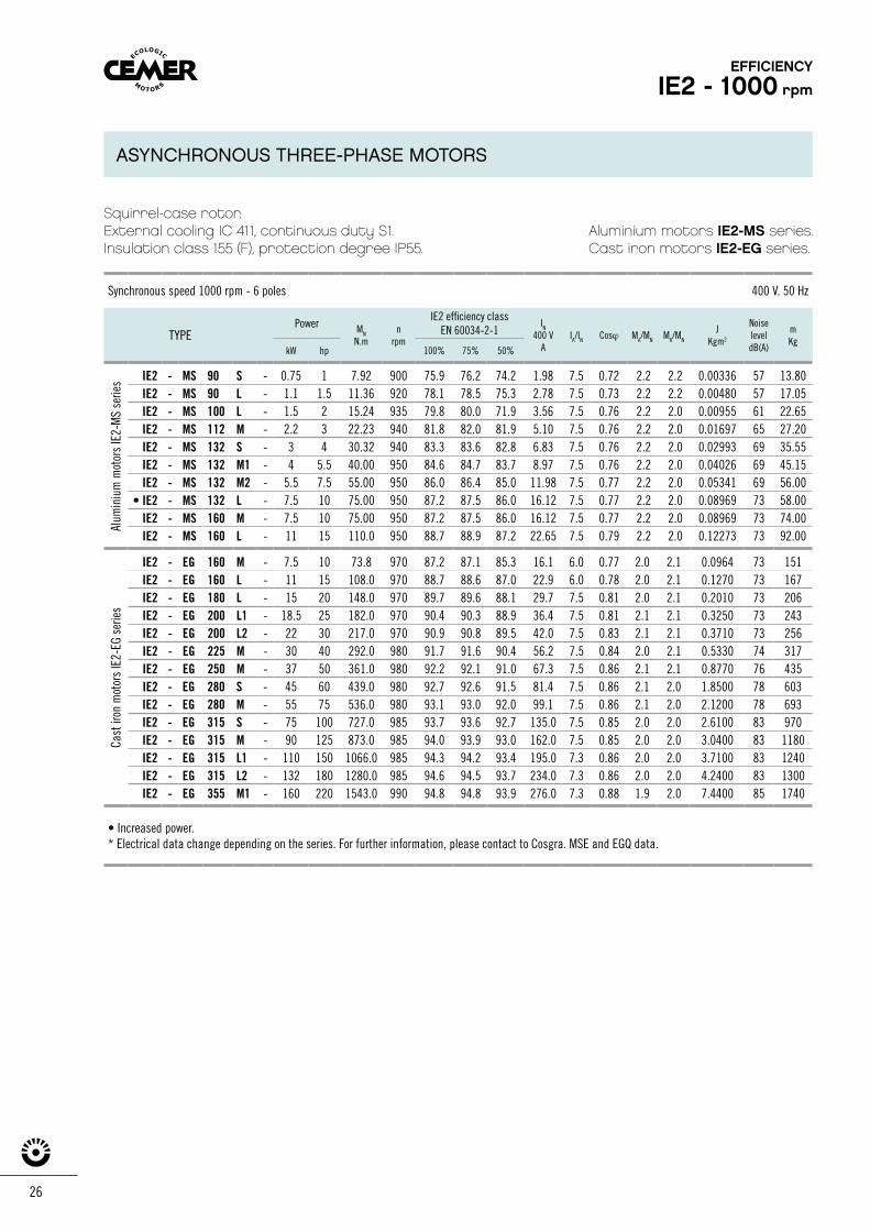
Squirrel-case rotor.External cooling IC 411, continuous duty S1.Insulation class 155 (F), protection degree IP55.
Aluminium motors IE2-MS series.Cast iron motors IE2-EG series.
Synchronous speed 1000 rpm - 6 poles 400 V. 50 Hz
TYPEPower MN
N.mn
rpm
IE2 efficiency classEN 60034-2-1
IN
400 VA
IA/IN Cosϕ MA/MN MK/MN
JKgm2
NoiseleveldB(A)
mKg
kW hp 100% 75% 50%
IE2 - MS 90 S - 0.75 1 7.92 900 75.9 76.2 74.2 1.98 7.5 0.72 2.2 2.2 0.00336 57 13.80 IE2 - MS 90 L - 1.1 1.5 11.36 920 78.1 78.5 75.3 2.78 7.5 0.73 2.2 2.2 0.00480 57 17.05 IE2 - MS 100 L - 1.5 2 15.24 935 79.8 80.0 71.9 3.56 7.5 0.76 2.2 2.0 0.00955 61 22.65 IE2 - MS 112 M - 2.2 3 22.23 940 81.8 82.0 81.9 5.10 7.5 0.76 2.2 2.0 0.01697 65 27.20IE2 - MS 132 S - 3 4 30.32 940 83.3 83.6 82.8 6.83 7.5 0.76 2.2 2.0 0.02993 69 35.55 IE2 - MS 132 M1 - 4 5.5 40.00 950 84.6 84.7 83.7 8.97 7.5 0.76 2.2 2.0 0.04026 69 45.15 IE2 - MS 132 M2 - 5.5 7.5 55.00 950 86.0 86.4 85.0 11.98 7.5 0.77 2.2 2.0 0.05341 69 56.00
• IE2 - MS 132 L - 7.5 10 75.00 950 87.2 87.5 86.0 16.12 7.5 0.77 2.2 2.0 0.08969 73 58.00IE2 - MS 160 M - 7.5 10 75.00 950 87.2 87.5 86.0 16.12 7.5 0.77 2.2 2.0 0.08969 73 74.00 IE2 - MS 160 L - 11 15 110.0 950 88.7 88.9 87.2 22.65 7.5 0.79 2.2 2.0 0.12273 73 92.00
IE2 - EG 160 M - 7.5 10 73.8 970 87.2 87.1 85.3 16.1 6.0 0.77 2.0 2.1 0.0964 73 151IE2 - EG 160 L - 11 15 108.0 970 88.7 88.6 87.0 22.9 6.0 0.78 2.0 2.1 0.1270 73 167IE2 - EG 180 L - 15 20 148.0 970 89.7 89.6 88.1 29.7 7.5 0.81 2.0 2.1 0.2010 73 206IE2 - EG 200 L1 - 18.5 25 182.0 970 90.4 90.3 88.9 36.4 7.5 0.81 2.1 2.1 0.3250 73 243IE2 - EG 200 L2 - 22 30 217.0 970 90.9 90.8 89.5 42.0 7.5 0.83 2.1 2.1 0.3710 73 256IE2 - EG 225 M - 30 40 292.0 980 91.7 91.6 90.4 56.2 7.5 0.84 2.0 2.1 0.5330 74 317IE2 - EG 250 M - 37 50 361.0 980 92.2 92.1 91.0 67.3 7.5 0.86 2.1 2.1 0.8770 76 435IE2 - EG 280 S - 45 60 439.0 980 92.7 92.6 91.5 81.4 7.5 0.86 2.1 2.0 1.8500 78 603IE2 - EG 280 M - 55 75 536.0 980 93.1 93.0 92.0 99.1 7.5 0.86 2.1 2.0 2.1200 78 693IE2 - EG 315 S - 75 100 727.0 985 93.7 93.6 92.7 135.0 7.5 0.85 2.0 2.0 2.6100 83 970IE2 - EG 315 M - 90 125 873.0 985 94.0 93.9 93.0 162.0 7.5 0.85 2.0 2.0 3.0400 83 1180IE2 - EG 315 L1 - 110 150 1066.0 985 94.3 94.2 93.4 195.0 7.3 0.86 2.0 2.0 3.7100 83 1240IE2 - EG 315 L2 - 132 180 1280.0 985 94.6 94.5 93.7 234.0 7.3 0.86 2.0 2.0 4.2400 83 1300IE2 - EG 355 M1 - 160 220 1543.0 990 94.8 94.8 93.9 276.0 7.3 0.88 1.9 2.0 7.4400 85 1740
• Increased power.* Electrical data change depending on the series. For further information, please contact to Cosgra. MSE and EGQ data.
Cast
iron
mot
ors
IE2-
EG s
erie
sAl
umin
ium
mot
ors
IE2-
MS
serie
s
EFFICIENCY
IE2 - 1000 rpm
ASYNCHRONOUS THREE-PHASE MOTORS
Squirrel-case rotor.External cooling IC 411, continuous duty S1.Insulation class 155 (F), protection degree IP55.
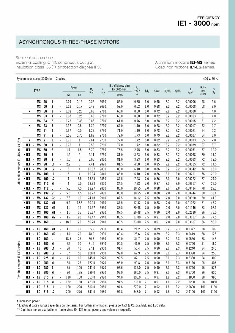
Aluminium motors IE1-MS series.Cast iron motors IE1-EG series.
Synchronous speed 3000 rpm - 2 poles 400 V. 50 Hz
TYPEPower MN
N.mn
rpm
IE1 efficiency class EN 60034-2-1
IN
400 VA
IA/IN Cosϕ MA/MN MK/MN
JKgm2
Noiselevel
dB(A)
mKg
kW hp 100%
MS 56 1 - 0.09 0.12 0.32 2660 56.0 0.35 6.0 0.65 2.2 2.2 0.00006 58 2.6MS 56 2 - 0.12 0.17 0.42 2690 58.0 0.52 6.0 0.68 2.2 2.2 0.00008 58 3.0
• MS 56 3 - 0.18 0.25 0.63 2710 60.0 0.60 6.0 0.72 2.2 2.2 0.00010 61 4.0MS 63 1 - 0.18 0.25 0.63 2710 60.0 0.60 6.0 0.72 2.2 2.2 0.00013 61 4.0MS 63 2 - 0.25 0.33 0.88 2710 61.0 0.76 6.0 0.78 2.2 2.2 0.00015 61 4.2
• MS 63 3 - 0.37 0.5 1.30 2710 64.0 1.10 6.0 0.78 2.2 2.2 0.00017 62 4.7MS 71 1 - 0.37 0.5 1.29 2730 71.0 1.10 6.0 0.78 2.2 2.2 0.00021 64 5.2MS 71 2 - 0.55 0.75 1.89 2760 72.0 1.73 6.0 0.79 2.2 2.2 0.00027 64 6.0
• MS 71 3 - 0.75 1 2.61 2730 77.0 1.72 6.0 0.82 2.2 2.2 0.00033 65 7.0IE1 - MS 80 1 - 0.75 1 2.58 2760 77.0 1.72 6.0 0.82 2.2 2.2 0.00039 67 8.7IE1 - MS 80 2 - 1.1 1.5 3.79 2760 78.5 2.45 6.0 0.83 2.2 2.2 0.00051 67 10.0
• IE1 - MS 80 3 - 1.5 2 5.11 2790 81.0 3.23 6.0 0.83 2.2 2.2 0.00068 70 11.2IE1 - MS 90 S - 1.5 2 5.05 2820 81.0 3.23 6.0 0.83 2.2 2.2 0.00093 72 12.0IE1 - MS 90 L1 - 2.2 3 7.41 2820 81.5 4.60 6.0 0.85 2.2 2.2 0.00115 72 14.5
• IE1 - MS 90 L2 - 3 4 10.07 2830 83.0 6.10 6.0 0.86 2.2 2.2 0.00142 74 15.0IE1 - MS 100 L1 - 3 4 10.04 2840 83.0 6.10 7.0 0.86 2.0 2.0 0.00211 76 20.0
• IE1 - MS 100 L2 - 4 5.5 13.33 2850 84.5 7.98 7.0 0.86 2.0 2.0 0.00272 77 24.0IE1 - MS 112 M - 4 5.5 13.33 2850 84.5 7.98 7.0 0.87 2.0 2.0 0.00317 77 26.0
• IE1 - MS 112 L - 5.5 7.5 18.27 2860 86.0 10.55 7.0 0.88 2.0 2.0 0.00434 78 29.3IE1 - MS 132 S1 - 5.5 7.5 18.27 2860 86.0 10.55 7.0 0.88 2.0 2.0 0.00744 80 38.4IE1 - MS 132 S2 - 7.5 10 24.48 2910 87.5 14.12 7.5 0.88 2.0 2.0 0.00910 80 41.3
• IE1 - MS 132 M1 - 9.2 12.5 30.03 2910 87.5 17.32 7.5 0.88 2.0 2.0 0.01072 81 48.2• IE1 - MS 132 M2 - 11 15 35.67 2930 87.5 20.48 7.5 0.90 2.0 2.0 0.01146 83 52.5
IE1 - MS 160 M1 - 11 15 35.67 2930 87.5 20.48 7.5 0.90 2.0 2.0 0.02380 86 76.0IE1 - MS 160 M2 - 15 20 48.47 2940 88.5 27.00 7.5 0.91 2.0 2.0 0.03117 86 77.5IE1 - MS 160 L - 18.5 25 59.78 2940 89.5 33.00 7.5 0.91 2.0 2.0 0.03617 86 92.0
IE1 - EG 160 M1 - 11 15 35.9 2930 88.4 21.2 7.5 0.89 2.2 2.3 0.0377 88 109IE1 - EG 160 M2 - 15 20 48.9 2930 89.4 28.6 7.5 0.89 2.2 2.3 0.0449 88 125IE1 - EG 160 L - 18.5 25 60.3 2930 90.0 34.7 7.5 0.90 2.2 2.3 0.0550 88 147IE1 - EG 180 M - 22 30 71.5 2940 90.5 41.0 7.5 0.90 2.0 2.3 0.0750 91 180IE1 - EG 200 L1 - 30 40 97.1 2950 91.4 55.4 7.5 0.90 2.0 2.3 0.1240 94 240IE1 - EG 200 L2 - 37 50 120.0 2950 92.0 67.9 7.5 0.90 2.0 2.3 0.1390 94 255IE1 - EG 225 M - 45 60 145.0 2970 92.5 82.1 7.5 0.90 2.0 2.3 0.2330 94 309IE1 - EG 250 M - 55 75 177.0 2970 93.0 99.8 7.5 0.90 2.0 2.3 0.3120 95 403IE1 - EG 280 S - 75 100 241.0 2970 93.6 135.0 7.5 0.90 2.0 2.3 0.5790 96 572IE1 - EG 280 M - 90 125 289.0 2970 93.9 160.0 7.5 0.91 2.0 2.3 0.6750 96 620IE1 - EG 315 S - 110 150 353.0 2980 94.0 195.0 7.1 0.91 1.8 2.2 1.1800 98 980IE1 - EG 315 M - 132 180 423.0 2980 94.5 233.0 7.1 0.91 1.8 2.2 1.8200 98 1080IE1 - EG 315 L1 - 160 220 513.0 2980 94.6 279.0 7.1 0.92 1.8 2.2 2.0800 101 1160IE1 - EG 315 L2 - 200 270 641.0 2980 94.8 348.0 7.1 0.92 1.8 2.2 2.4100 101 1190
• Increased power.* Electrical data change depending on the series. For further information, please contact to Cosgra. MSE and EGQ data.** Cast iron motors available for frame sizes 80 -132 (other powers and values on request).
Cast
iron
mot
ors
IE1-
EG s
erie
sAl
umin
ium
mot
ors
IE1-
MS
serie
s (*
*)EFFICIENCY
IE1 - 3000 rpm
ASYNCHRONOUS THREE-PHASE MOTORS
28
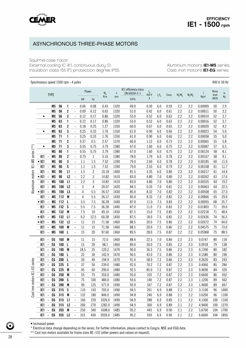
Squirrel-case rotor.External cooling IC 411, continuous duty S1.Insulation class 155 (F), protection degree IP55.
Aluminium motors IE1-MS series.Cast iron motors IE1-EG series.
Synchronous speed 1500 rpm - 4 poles 400 V. 50 Hz
TYPEPower MN
N.mn
rpm
IE1 efficiency classEN 60034-2-1
IN
400 VA
IA/IN Cosϕ MA/MN MK/MN
JKgm2
Noise leveldB(A)
mKg
kW hp 100%
MS 56 1 - 0.06 0.08 0.43 1320 49.0 0.30 6.0 0.59 2.2 2.2 0.00009 50 2.9MS 56 2 - 0.09 0.12 0.65 1320 51.0 0.42 6.0 0.61 2.2 2.2 0.00011 50 3.2
• MS 56 3 - 0.12 0.17 0.86 1320 53.0 0.52 6.0 0.63 2.2 2.2 0.00014 52 3.7MS 63 1 - 0.12 0.17 0.86 1320 53.0 0.52 6.0 0.63 2.2 2.2 0.00016 52 3.7MS 63 2 - 0.18 0.25 1.27 1350 60.0 0.67 6.0 0.65 2.2 2.2 0.00020 52 4.2
• MS 63 3 - 0.25 0.33 1.76 1350 61.0 0.90 6.0 0.66 2.2 2.2 0.00023 54 5.0MS 71 1 - 0.25 0.33 1.76 1350 61.0 0.90 6.0 0.66 2.2 2.2 0.00058 55 5.0MS 71 2 - 0.37 0.5 2.57 1370 66.0 1.12 6.0 0.73 2.2 2.2 0.00065 55 5.8
• MS 71 3 - 0.55 0.75 3.79 1380 67.0 1.60 6.0 0.75 2.2 2.2 0.00087 57 6.5MS 80 1 - 0.55 0.75 3.79 1380 67.0 1.60 6.0 0.75 2.2 2.2 0.00124 58 8.1
IE1 - MS 80 2 - 0.75 1 5.16 1380 78.0 1.79 6.0 0.78 2.2 2.2 0.00167 58 9.1• IE1 MS 80 3 - 1.1 1.5 7.52 1390 79.0 2.60 6.0 0.78 2.2 2.2 0.00185 60 11.0
IE1 - MS 90 S - 1.1 1.5 7.52 1390 79.0 2.55 6.0 0.79 2.2 2.2 0.00168 61 11.7IE1 - MS 90 L1 - 1.5 2 10.18 1400 81.5 3.35 6.0 0.80 2.2 2.2 0.00217 61 14.4
• IE1 - MS 90 L2 - 2.2 3 14.82 1410 83.0 4.80 7.0 0.80 2.2 2.2 0.00262 63 17.6IE1 - MS 100 L1 - 2.2 3 14.82 1410 83.0 4.80 7.0 0.80 2.2 2.2 0.00335 64 19.2IE1 - MS 100 L2 - 3 4 20.07 1420 84.5 6.35 7.0 0.81 2.2 2.2 0.00463 64 22.5
• IE1 - MS 100 L3 - 4 5.5 26.57 1430 85.0 8.32 7.0 0.82 2.2 2.2 0.00508 65 27.3IE1 - MS 112 M - 4 5.5 26.57 1430 85.0 8.32 7.0 0.82 2.2 2.2 0.00866 65 29.0
• IE1 - MS 112 L - 5.5 7.5 36.28 1440 87.0 11.0 7.5 0.83 2.2 2.2 0.00955 68 35.7IE1 - MS 132 S - 5.5 7.5 36.28 1440 87.0 11.0 7.5 0.83 2.2 2.2 0.01803 71 39.0IE1 - MS 132 M - 7.5 10 49.14 1450 87.5 15.0 7.5 0.85 2.2 2.2 0.02218 71 48.6
• IE1 - MS 132 L1 - 9.2 12.5 60.28 1450 87.5 18.0 7.5 0.85 2.2 2.2 0.02436 74 56.5• IE1 - MS 132 L2 - 11 15 71.58 1460 88.5 20.0 7.5 0.86 2.2 2.2 0.02672 74 64.0
IE1 - MS 160 M - 11 15 71.58 1460 88.5 20.0 7.5 0.86 2.2 2.2 0.04575 75 73.0IE1 - MS 160 L - 15 20 97.60 1460 89.5 28.0 7.5 0.87 2.2 2.2 0.05968 75 88.5
IE1 - EG 160 M - 11 15 72.0 1460 88.4 22.5 7.0 0.84 2.2 2.3 0.0747 80 118IE1 - EG 160 L - 15 20 98.1 1460 89.4 30.0 7.5 0.85 2.2 2.3 0.0918 79 138IE1 - EG 180 M - 18.5 25 120.2 1470 90.0 36.3 7.5 0.86 2.2 2.3 0.1390 80 182IE1 - EG 180 L - 22 30 142.9 1470 90.5 43.0 7.5 0.86 2.2 2.3 0.1580 80 190IE1 - EG 200 L - 30 40 194.9 1470 91.4 58.0 7.2 0.86 2.2 2.3 0.2620 83 243IE1 - EG 225 S - 37 50 239.0 1480 92.0 70.2 7.2 0.87 2.2 2.3 0.4060 85 284IE1 - EG 225 M - 45 60 290.0 1480 92.5 85.0 7.2 0.87 2.2 2.3 0.4690 84 320IE1 - EG 250 M - 55 75 355.0 1480 93.0 103 7.2 0.87 2.2 2.3 0.6600 86 452IE1 - EG 280 S - 75 100 484.0 1480 93.6 140 7.2 0.87 2.2 2.3 1.1200 89 562IE1 - EG 280 M - 90 125 577.0 1490 93.9 167 7.2 0.87 2.2 2.3 1.4600 89 667IE1 - EG 315 S - 110 150 705.0 1490 94.5 201 6.9 0.88 2.1 2.2 3.1100 96 1000IE1 - EG 315 M - 132 180 846.0 1490 94.8 240 6.9 0.88 2.1 2.2 3.6200 96 1100IE1 - EG 315 L1 - 160 220 1026.0 1490 94.9 288 6.9 0.89 2.1 2.2 4.1300 100 1160IE1 - EG 315 L2 - 200 270 1282.0 1490 94.9 360 6.9 0.89 2.1 2.2 4.9400 100 1270IE1 - EG 355 M - 250 340 1608.0 1485 95.2 443 6.9 0.90 2.1 2.2 5.6700 104 1700IE1 - EG 355 L2 - 315 430 2026.0 1485 95.2 559 6.9 0.90 2.1 2.2 6.6600 104 1850
• Increased power.* Electrical data change depending on the series. For further information, please contact to Cosgra. MSE and EGQ data.** Cast iron motors available for frame sizes 80 -132 (other powers and values on request).
Cast
iron
mot
ors
IE1-
EG s
erie
sAl
umin
ium
mot
ors
IE1-
MS
serie
s (*
*)
EFFICIENCY
IE1 - 1500 rpm
ASYNCHRONOUS THREE-PHASE MOTORS
Synchronous speed 1500 rpm - 4 poles 400 V. 50 Hz
TYPEPower MN
N.mn
rpm
IE1 efficiency classEN 60034-2-1
IN
400 VA
IA/IN Cosϕ MA/MN MK/MN
JKgm2
Noise leveldB(A)
mKg
kW hp 100%
MS 56 1 - 0.06 0.08 0.43 1320 49.0 0.30 6.0 0.59 2.2 2.2 0.00009 50 2.9MS 56 2 - 0.09 0.12 0.65 1320 51.0 0.42 6.0 0.61 2.2 2.2 0.00011 50 3.2
• MS 56 3 - 0.12 0.17 0.86 1320 53.0 0.52 6.0 0.63 2.2 2.2 0.00014 52 3.7MS 63 1 - 0.12 0.17 0.86 1320 53.0 0.52 6.0 0.63 2.2 2.2 0.00016 52 3.7MS 63 2 - 0.18 0.25 1.27 1350 60.0 0.67 6.0 0.65 2.2 2.2 0.00020 52 4.2
• MS 63 3 - 0.25 0.33 1.76 1350 61.0 0.90 6.0 0.66 2.2 2.2 0.00023 54 5.0MS 71 1 - 0.25 0.33 1.76 1350 61.0 0.90 6.0 0.66 2.2 2.2 0.00058 55 5.0MS 71 2 - 0.37 0.5 2.57 1370 66.0 1.12 6.0 0.73 2.2 2.2 0.00065 55 5.8
• MS 71 3 - 0.55 0.75 3.79 1380 67.0 1.60 6.0 0.75 2.2 2.2 0.00087 57 6.5MS 80 1 - 0.55 0.75 3.79 1380 67.0 1.60 6.0 0.75 2.2 2.2 0.00124 58 8.1
IE1 - MS 80 2 - 0.75 1 5.16 1380 78.0 1.79 6.0 0.78 2.2 2.2 0.00167 58 9.1• IE1 MS 80 3 - 1.1 1.5 7.52 1390 79.0 2.60 6.0 0.78 2.2 2.2 0.00185 60 11.0
IE1 - MS 90 S - 1.1 1.5 7.52 1390 79.0 2.55 6.0 0.79 2.2 2.2 0.00168 61 11.7IE1 - MS 90 L1 - 1.5 2 10.18 1400 81.5 3.35 6.0 0.80 2.2 2.2 0.00217 61 14.4
• IE1 - MS 90 L2 - 2.2 3 14.82 1410 83.0 4.80 7.0 0.80 2.2 2.2 0.00262 63 17.6IE1 - MS 100 L1 - 2.2 3 14.82 1410 83.0 4.80 7.0 0.80 2.2 2.2 0.00335 64 19.2IE1 - MS 100 L2 - 3 4 20.07 1420 84.5 6.35 7.0 0.81 2.2 2.2 0.00463 64 22.5
• IE1 - MS 100 L3 - 4 5.5 26.57 1430 85.0 8.32 7.0 0.82 2.2 2.2 0.00508 65 27.3IE1 - MS 112 M - 4 5.5 26.57 1430 85.0 8.32 7.0 0.82 2.2 2.2 0.00866 65 29.0
• IE1 - MS 112 L - 5.5 7.5 36.28 1440 87.0 11.0 7.5 0.83 2.2 2.2 0.00955 68 35.7IE1 - MS 132 S - 5.5 7.5 36.28 1440 87.0 11.0 7.5 0.83 2.2 2.2 0.01803 71 39.0IE1 - MS 132 M - 7.5 10 49.14 1450 87.5 15.0 7.5 0.85 2.2 2.2 0.02218 71 48.6
• IE1 - MS 132 L1 - 9.2 12.5 60.28 1450 87.5 18.0 7.5 0.85 2.2 2.2 0.02436 74 56.5• IE1 - MS 132 L2 - 11 15 71.58 1460 88.5 20.0 7.5 0.86 2.2 2.2 0.02672 74 64.0
IE1 - MS 160 M - 11 15 71.58 1460 88.5 20.0 7.5 0.86 2.2 2.2 0.04575 75 73.0IE1 - MS 160 L - 15 20 97.60 1460 89.5 28.0 7.5 0.87 2.2 2.2 0.05968 75 88.5
IE1 - EG 160 M - 11 15 72.0 1460 88.4 22.5 7.0 0.84 2.2 2.3 0.0747 80 118IE1 - EG 160 L - 15 20 98.1 1460 89.4 30.0 7.5 0.85 2.2 2.3 0.0918 79 138IE1 - EG 180 M - 18.5 25 120.2 1470 90.0 36.3 7.5 0.86 2.2 2.3 0.1390 80 182IE1 - EG 180 L - 22 30 142.9 1470 90.5 43.0 7.5 0.86 2.2 2.3 0.1580 80 190IE1 - EG 200 L - 30 40 194.9 1470 91.4 58.0 7.2 0.86 2.2 2.3 0.2620 83 243IE1 - EG 225 S - 37 50 239.0 1480 92.0 70.2 7.2 0.87 2.2 2.3 0.4060 85 284IE1 - EG 225 M - 45 60 290.0 1480 92.5 85.0 7.2 0.87 2.2 2.3 0.4690 84 320IE1 - EG 250 M - 55 75 355.0 1480 93.0 103 7.2 0.87 2.2 2.3 0.6600 86 452IE1 - EG 280 S - 75 100 484.0 1480 93.6 140 7.2 0.87 2.2 2.3 1.1200 89 562IE1 - EG 280 M - 90 125 577.0 1490 93.9 167 7.2 0.87 2.2 2.3 1.4600 89 667IE1 - EG 315 S - 110 150 705.0 1490 94.5 201 6.9 0.88 2.1 2.2 3.1100 96 1000IE1 - EG 315 M - 132 180 846.0 1490 94.8 240 6.9 0.88 2.1 2.2 3.6200 96 1100IE1 - EG 315 L1 - 160 220 1026.0 1490 94.9 288 6.9 0.89 2.1 2.2 4.1300 100 1160IE1 - EG 315 L2 - 200 270 1282.0 1490 94.9 360 6.9 0.89 2.1 2.2 4.9400 100 1270IE1 - EG 355 M - 250 340 1608.0 1485 95.2 443 6.9 0.90 2.1 2.2 5.6700 104 1700IE1 - EG 355 L2 - 315 430 2026.0 1485 95.2 559 6.9 0.90 2.1 2.2 6.6600 104 1850
• Increased power.* Electrical data change depending on the series. For further information, please contact to Cosgra. MSE and EGQ data.** Cast iron motors available for frame sizes 80 -132 (other powers and values on request).
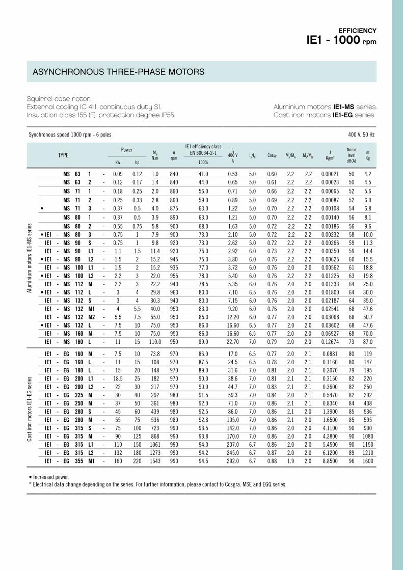
Squirrel-case rotor.External cooling IC 411, continuous duty S1.Insulation class 155 (F), protection degree IP55.
Aluminium motors IE1-MS series.Cast iron motors IE1-EG series.
Synchronous speed 1000 rpm - 6 poles 400 V. 50 Hz
TYPEPower MN
N.mn
rpm
IE1 efficiency classEN 60034-2-1
IN
400 VA
IA/IN Cosϕ MA/MN MK/MN
JKgm2
NoiseleveldB(A)
mKg
kW hp 100%
MS 63 1 - 0.09 0.12 1.0 840 41.0 0.53 5.0 0.60 2.2 2.2 0.00021 50 4.2MS 63 2 - 0.12 0.17 1.4 840 44.0 0.65 5.0 0.61 2.2 2.2 0.00023 50 4.5
MS 71 1 - 0.18 0.25 2.0 860 56.0 0.71 5.0 0.66 2.2 2.2 0.00065 52 5.6
MS 71 2 - 0.25 0.33 2.8 860 59.0 0.89 5.0 0.69 2.2 2.2 0.00087 52 6.0• MS 71 3 - 0.37 0.5 4.0 875 63.0 1.22 5.0 0.70 2.2 2.2 0.00108 54 6.8
MS 80 1 - 0.37 0.5 3.9 890 63.0 1.21 5.0 0.70 2.2 2.2 0.00140 56 8.1
MS 80 2 - 0.55 0.75 5.8 900 68.0 1.63 5.0 0.72 2.2 2.2 0.00186 56 9.6• IE1 - MS 80 3 - 0.75 1 7.9 900 73.0 2.10 5.0 0.72 2.2 2.2 0.00232 58 10.0
IE1 - MS 90 S - 0.75 1 9.8 920 73.0 2.62 5.0 0.72 2.2 2.2 0.00266 59 11.3IE1 - MS 90 L1 - 1.1 1.5 11.4 920 75.0 2.92 6.0 0.73 2.2 2.2 0.00350 59 14.4
• IE1 - MS 90 L2 - 1.5 2 15.2 945 75.0 3.80 6.0 0.76 2.2 2.2 0.00625 60 15.5IE1 - MS 100 L1 - 1.5 2 15.2 935 77.0 3.72 6.0 0.76 2.0 2.0 0.00562 61 18.8
• IE1 - MS 100 L2 - 2.2 3 22.0 955 78.0 5.40 6.0 0.76 2.2 2.2 0.01225 63 19.8IE1 - MS 112 M - 2.2 3 22.2 940 78.5 5.35 6.0 0.76 2.0 2.0 0.01333 64 25.0
• IE1 - MS 112 L - 3 4 29.8 960 80.0 7.10 6.5 0.76 2.0 2.0 0.01800 64 30.0IE1 - MS 132 S - 3 4 30.3 940 80.0 7.15 6.0 0.76 2.0 2.0 0.02187 64 35.0IE1 - MS 132 M1 - 4 5.5 40.0 950 83.0 9.20 6.0 0.76 2.0 2.0 0.02541 68 47.6IE1 - MS 132 M2 - 5.5 7.5 55.0 950 85.0 12.20 6.0 0.77 2.0 2.0 0.03068 68 50.7
• IE1 - MS 132 L - 7.5 10 75.0 950 86.0 16.60 6.5 0.77 2.0 2.0 0.03602 68 47.6IE1 - MS 160 M - 7.5 10 75.0 950 86.0 16.60 6.5 0.77 2.0 2.0 0.06927 68 70.0IE1 - MS 160 L - 11 15 110.0 950 89.0 22.70 7.0 0.79 2.0 2.0 0.12674 73 87.0
IE1 - EG 160 M - 7.5 10 73.8 970 86.0 17.0 6.5 0.77 2.0 2.1 0.0881 80 119IE1 - EG 160 L - 11 15 108 970 87.5 24.5 6.5 0.78 2.0 2.1 0.1160 80 147IE1 - EG 180 L - 15 20 148 970 89.0 31.6 7.0 0.81 2.0 2.1 0.2070 79 195IE1 - EG 200 L1 - 18.5 25 182 970 90.0 38.6 7.0 0.81 2.1 2.1 0.3150 82 220IE1 - EG 200 L2 - 22 30 217 970 90.0 44.7 7.0 0.83 2.1 2.1 0.3600 82 250IE1 - EG 225 M - 30 40 292 980 91.5 59.3 7.0 0.84 2.0 2.1 0.5470 82 292IE1 - EG 250 M - 37 50 361 980 92.0 71.0 7.0 0.86 2.1 2.1 0.8340 84 408IE1 - EG 280 S - 45 60 439 980 92.5 86.0 7.0 0.86 2.1 2.0 1.3900 85 536IE1 - EG 280 M - 55 75 536 980 92.8 105.0 7.0 0.86 2.1 2.0 1.6500 85 595IE1 - EG 315 S - 75 100 723 990 93.5 142.0 7.0 0.86 2.0 2.0 4.1100 90 990IE1 - EG 315 M - 90 125 868 990 93.8 170.0 7.0 0.86 2.0 2.0 4.2800 90 1080IE1 - EG 315 L1 - 110 150 1061 990 94.0 207.0 6.7 0.86 2.0 2.0 5.4500 90 1150IE1 - EG 315 L2 - 132 180 1273 990 94.2 245.0 6.7 0.87 2.0 2.0 6.1200 89 1210IE1 - EG 355 M1 - 160 220 1543 990 94.5 292.0 6.7 0.88 1.9 2.0 8.8500 96 1600
• Increased power.* Electrical data change depending on the series. For further information, please contact to Cosgra. MSE and EGQ series.
Cast
iron
mot
ors
IE1-
EG s
erie
sAl
umin
ium
mot
ors
IE1-
MS
serie
sEFFICIENCY
IE1 - 1000 rpm
ASYNCHRONOUS THREE-PHASE MOTORS
30
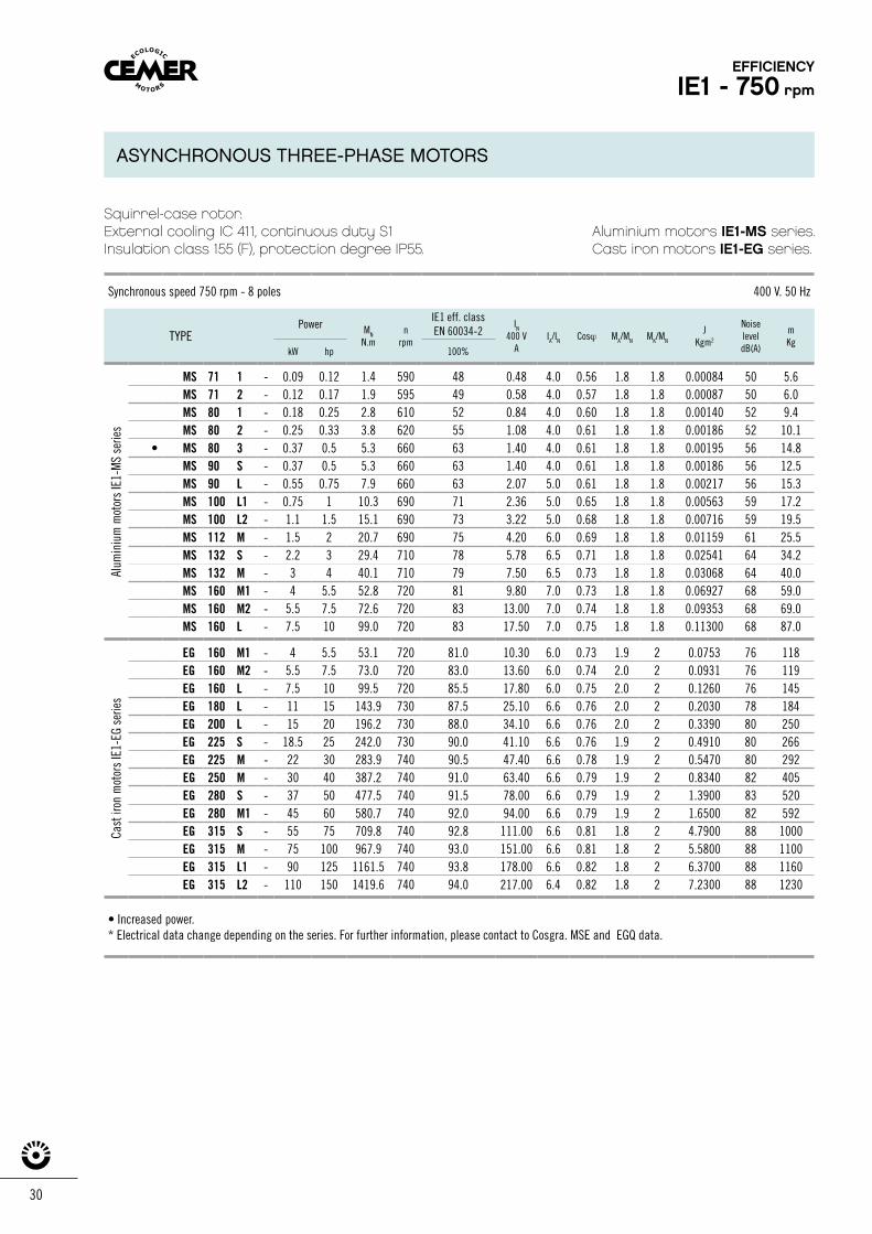
Squirrel-case rotor.External cooling IC 411, continuous duty S1Insulation class 155 (F), protection degree IP55.
Aluminium motors IE1-MS series.Cast iron motors IE1-EG series.
Synchronous speed 750 rpm - 8 poles 400 V. 50 Hz
TYPEPower MN
N.mn
rpm
IE1 eff. classEN 60034-2
IN
400 VA
IA/IN Cosϕ MA/MN MK/MN
JKgm2
Noise level dB(A)
mKg
kW hp 100%
MS 71 1 - 0.09 0.12 1.4 590 48 0.48 4.0 0.56 1.8 1.8 0.00084 50 5.6MS 71 2 - 0.12 0.17 1.9 595 49 0.58 4.0 0.57 1.8 1.8 0.00087 50 6.0MS 80 1 - 0.18 0.25 2.8 610 52 0.84 4.0 0.60 1.8 1.8 0.00140 52 9.4MS 80 2 - 0.25 0.33 3.8 620 55 1.08 4.0 0.61 1.8 1.8 0.00186 52 10.1
• MS 80 3 - 0.37 0.5 5.3 660 63 1.40 4.0 0.61 1.8 1.8 0.00195 56 14.8MS 90 S - 0.37 0.5 5.3 660 63 1.40 4.0 0.61 1.8 1.8 0.00186 56 12.5MS 90 L - 0.55 0.75 7.9 660 63 2.07 5.0 0.61 1.8 1.8 0.00217 56 15.3MS 100 L1 - 0.75 1 10.3 690 71 2.36 5.0 0.65 1.8 1.8 0.00563 59 17.2MS 100 L2 - 1.1 1.5 15.1 690 73 3.22 5.0 0.68 1.8 1.8 0.00716 59 19.5MS 112 M - 1.5 2 20.7 690 75 4.20 6.0 0.69 1.8 1.8 0.01159 61 25.5MS 132 S - 2.2 3 29.4 710 78 5.78 6.5 0.71 1.8 1.8 0.02541 64 34.2MS 132 M - 3 4 40.1 710 79 7.50 6.5 0.73 1.8 1.8 0.03068 64 40.0MS 160 M1 - 4 5.5 52.8 720 81 9.80 7.0 0.73 1.8 1.8 0.06927 68 59.0MS 160 M2 - 5.5 7.5 72.6 720 83 13.00 7.0 0.74 1.8 1.8 0.09353 68 69.0MS 160 L - 7.5 10 99.0 720 83 17.50 7.0 0.75 1.8 1.8 0.11300 68 87.0
EG 160 M1 - 4 5.5 53.1 720 81.0 10.30 6.0 0.73 1.9 2 0.0753 76 118EG 160 M2 - 5.5 7.5 73.0 720 83.0 13.60 6.0 0.74 2.0 2 0.0931 76 119EG 160 L - 7.5 10 99.5 720 85.5 17.80 6.0 0.75 2.0 2 0.1260 76 145EG 180 L - 11 15 143.9 730 87.5 25.10 6.6 0.76 2.0 2 0.2030 78 184EG 200 L - 15 20 196.2 730 88.0 34.10 6.6 0.76 2.0 2 0.3390 80 250EG 225 S - 18.5 25 242.0 730 90.0 41.10 6.6 0.76 1.9 2 0.4910 80 266EG 225 M - 22 30 283.9 740 90.5 47.40 6.6 0.78 1.9 2 0.5470 80 292EG 250 M - 30 40 387.2 740 91.0 63.40 6.6 0.79 1.9 2 0.8340 82 405EG 280 S - 37 50 477.5 740 91.5 78.00 6.6 0.79 1.9 2 1.3900 83 520EG 280 M1 - 45 60 580.7 740 92.0 94.00 6.6 0.79 1.9 2 1.6500 82 592EG 315 S - 55 75 709.8 740 92.8 111.00 6.6 0.81 1.8 2 4.7900 88 1000EG 315 M - 75 100 967.9 740 93.0 151.00 6.6 0.81 1.8 2 5.5800 88 1100EG 315 L1 - 90 125 1161.5 740 93.8 178.00 6.6 0.82 1.8 2 6.3700 88 1160EG 315 L2 - 110 150 1419.6 740 94.0 217.00 6.4 0.82 1.8 2 7.2300 88 1230
• Increased power.* Electrical data change depending on the series. For further information, please contact to Cosgra. MSE and EGQ data.
Cast
iron
mot
ors
IE1-
EG s
erie
sAl
umin
ium
mot
ors
IE1-
MS
serie
s
EFFICIENCY
IE1 - 750 rpm
ASYNCHRONOUS THREE-PHASE MOTORS
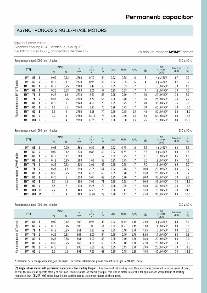
Aluminium motors MY/MYT series.
Squirrel-case rotor.External cooling IC 411, continuous duty S1Insulation class 155 (F), protection degree IP55.
Synchronous speed 3000 rpm - 2 poles 230 V. 50 Hz
TYPEPower n
rpm
IN
230 VA
η%
Cosϕ MA/MN MS/MN
IA
(A)
Run capacitor
(µf/V)
Noise leveldB(A)
mKgkW hp
MY 56 1 - 0.09 0.12 2760 0.79 54 0.92 0.65 1.6 3 4 µf/450V 67 2.9MY 56 2 - 0.12 0.17 2770 0.98 58 0.92 0.65 1.6 4 6 µf/450V 67 3.2
MYT 63 1 - 0.18 0.25 2700 1.47 56 0.95 0.65 1.7 5 10 μf/450V 70 4.0MYT 63 2 - 0.25 0.33 2700 2.00 57 0.95 0.65 1.7 7 12 μf/450V 70 4.5MYT 71 1 - 0.37 0.5 2710 2.61 65 0.95 0.70 1.7 10 20 μf/450V 75 5.1MYT 71 2 - 0.55 0.75 2740 3.70 68 0.95 0.70 1.7 15 25 μf/450V 75 7.2MYT 80 1 - 0.75 1 2740 4.90 70 0.95 0.75 1.7 20 30 µf/450V 75 9.6MYT 80 2 - 1.1 1.5 2740 6.83 73 0.96 0.75 1.7 30 40 µf/450V 78 11.0MYT 90 S - 1.5 2 2750 9.18 74 0.96 0.75 1.7 45 50 µf/450V 80 14.0MYT 90 L - 2.2 3 2750 13.11 76 0.96 0.60 1.7 65 60 μf/450V 80 16.5MYT 100 L - 3 4 2750 17.20 79 0.96 0.60 1.7 75 70 µf/450V 83 25.0
Synchronous speed 1500 rpm - 4 poles 230 V. 50 Hz
TYPEPower n
rpm
IN
230 VA
η%
Cosϕ MA/MN MS/MN
IA
(A)
Run capacitor
(µf/V)
Noise leveldB(A)
mKgkW hp
MY 56 1 - 0.06 0.09 1360 0.59 48 0.92 0.75 1.6 2.5 4 μf/450V 63 3.5MYT 56 2 - 0.09 0.12 1370 0.85 50 0.92 0.75 1.7 2.5 6 μf/450V 63 3.8MYT 63 1 - 0.12 0.17 1380 1.10 52 0.92 0.75 1.7 3.5 10 μf/450V 65 4.0MYT 63 2 - 0.18 0.25 1380 1.61 53 0.95 0.75 1.7 5.0 12 μf/450V 65 4.6MYT 71 1 - 0.25 0.33 1320 2.01 57 0.95 0.75 1.7 7.0 16 µf/450V 65 5.7MYT 71 2 - 0.37 0.5 1340 2.78 61 0.92 0.75 1.7 10.0 20 µf/450V 68 6.7MYT 80 1 - 0.55 0.75 1350 4.13 63 0.95 0.70 1.7 15.0 25 µf/450V 70 9.2MYT 80 2 - 0.75 1 1350 5.05 68 0.95 0.70 1.7 20.0 35 µf/450V 70 9.0MYT 90 S - 1.1 1.5 1350 7.09 71 0.95 0.65 1.7 30.0 45 µf/450V 73 14.5MYT 90 L - 1.5 2 1370 9.28 74 0.95 0.65 1.7 45.0 50 µf/450V 75 16.2MYT 100 L1 - 2.2 3 1400 12.77 78 0.96 0.47 1.7 65.0 70 µf/450V 78 24.0MYT 100 L2 3 4 1400 17.20 79 0.96 0.47 1.7 75.0 90 µf/450V 80 32.0
Synchronous speed 1000 rpm - 6 poles 230 V. 50 Hz
TYPEPower n
rpm
IN
230 VA
η%
Cosϕ MA/MN MS/MN
IA
(A)
Run capacitor
(µf/V)
Noise leveldB(A)
mKgkW hp
MY 63 1 - 0.09 0.12 900 0.92 46 0.92 0.55 1.45 2.00 8 µf/450V 63 5.1MY 63 2 - 0.12 0.16 900 1.05 54 0.92 0.55 1.45 3.00 11 µf/450V 63 6.0MY 71 1 - 0.18 0.25 851 1.33 52 0.95 0.40 1.70 4.65 10 µf/450V 68 6.3MY 71 2 - 0.25 0.33 856 2.00 54 0.95 0.40 1.70 8.00 14 µf/450V 68 7.6MY 80 1 - 0.37 0.55 861 3.00 55 0.95 0.40 1.70 15.0 20 µf/450V 68 9.0MY 80 2 - 0.55 0.75 863 4.50 56 0.95 0.40 1.70 27.0 20 µf/450V 70 11.6MY 90 S - 0.75 1 890 5.60 60 0.95 0.45 1.70 33.6 25 µf/450V 70 13.5MY 90 L - 1.1 1.5 891 7.50 63 0.95 0.45 1.60 45.0 40 µf/450V 70 16.2
* Electrical data change depending on the series. For further information, please contact to Cosgra. MYTE/MYE data.
(*) Single-phase motor with permanent capacitor – low starting torque. It has two identical windings and the capacitor is connected in series to one of them, so that the motor can operate staidly at full-load. Because of its low starting torque, this kind of motor is suitable for applications where torque at starting moment is low. CEMER MYT series have higher starting torque than other motors on the market.
Permanent capacitorAl
umin
ium
mot
ors
MY/
MYT
ser
ies
Alum
iniu
m m
otor
s M
Y se
ries
Alum
iniu
m m
otor
s M
Y/M
YT s
erie
s
ASYNCHRONOUS SINGLE-PHASE MOTORS
32
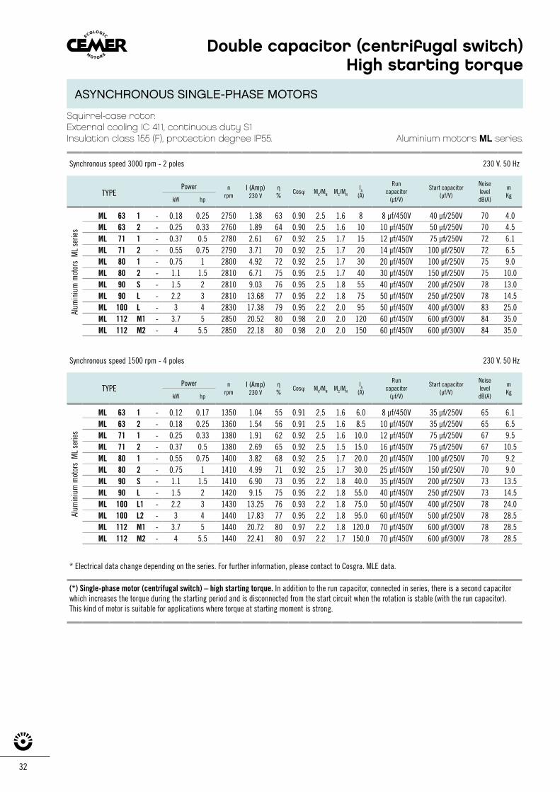
Squirrel-case rotor.External cooling IC 411, continuous duty S1Insulation class 155 (F), protection degree IP55.
Synchronous speed 3000 rpm - 2 poles 230 V. 50 Hz
TYPEPower n
rpmI (Amp)
230 Vη%
Cosϕ MA/MN MS/MN
IA
(A)
Runcapacitor
(µf/V)
Start capacitor (µf/V)
NoiseleveldB(A)
mKg
kW hp
ML 63 1 - 0.18 0.25 2750 1.38 63 0.90 2.5 1.6 8 8 µf/450V 40 µf/250V 70 4.0ML 63 2 - 0.25 0.33 2760 1.89 64 0.90 2.5 1.6 10 10 µf/450V 50 µf/250V 70 4.5ML 71 1 - 0.37 0.5 2780 2.61 67 0.92 2.5 1.7 15 12 µf/450V 75 µf/250V 72 6.1ML 71 2 - 0.55 0.75 2790 3.71 70 0.92 2.5 1.7 20 14 µf/450V 100 µf/250V 72 6.5ML 80 1 - 0.75 1 2800 4.92 72 0.92 2.5 1.7 30 20 µf/450V 100 µf/250V 75 9.0ML 80 2 - 1.1 1.5 2810 6.71 75 0.95 2.5 1.7 40 30 µf/450V 150 µf/250V 75 10.0ML 90 S - 1.5 2 2810 9.03 76 0.95 2.5 1.8 55 40 µf/450V 200 µf/250V 78 13.0ML 90 L - 2.2 3 2810 13.68 77 0.95 2.2 1.8 75 50 µf/450V 250 µf/250V 78 14.5ML 100 L - 3 4 2830 17.38 79 0.95 2.2 2.0 95 50 µf/450V 400 µf/300V 83 25.0ML 112 M1 - 3.7 5 2850 20.52 80 0.98 2.0 2.0 120 60 µf/450V 600 µf/300V 84 35.0ML 112 M2 - 4 5.5 2850 22.18 80 0.98 2.0 2.0 150 60 µf/450V 600 µf/300V 84 35.0
Synchronous speed 1500 rpm - 4 poles 230 V. 50 Hz
TYPEPower n
rpmI (Amp)
230 Vη%
Cosϕ MA/MN MS/MN
IA
(A)
Runcapacitor
(µf/V)
Start capacitor (µf/V)
NoiseleveldB(A)
mKg
kW hp
ML 63 1 - 0.12 0.17 1350 1.04 55 0.91 2.5 1.6 6.0 8 µf/450V 35 µf/250V 65 6.1ML 63 2 - 0.18 0.25 1360 1.54 56 0.91 2.5 1.6 8.5 10 µf/450V 35 µf/250V 65 6.5ML 71 1 - 0.25 0.33 1380 1.91 62 0.92 2.5 1.6 10.0 12 µf/450V 75 µf/250V 67 9.5ML 71 2 - 0.37 0.5 1380 2.69 65 0.92 2.5 1.5 15.0 16 µf/450V 75 µf/250V 67 10.5ML 80 1 - 0.55 0.75 1400 3.82 68 0.92 2.5 1.7 20.0 20 µf/450V 100 µf/250V 70 9.2ML 80 2 - 0.75 1 1410 4.99 71 0.92 2.5 1.7 30.0 25 µf/450V 150 µf/250V 70 9.0ML 90 S - 1.1 1.5 1410 6.90 73 0.95 2.2 1.8 40.0 35 µf/450V 200 µf/250V 73 13.5ML 90 L - 1.5 2 1420 9.15 75 0.95 2.2 1.8 55.0 40 µf/450V 250 µf/250V 73 14.5ML 100 L1 - 2.2 3 1430 13.25 76 0.93 2.2 1.8 75.0 50 µf/450V 400 µf/250V 78 24.0ML 100 L2 - 3 4 1440 17.83 77 0.95 2.2 1.8 95.0 60 µf/450V 500 µf/250V 78 28.5ML 112 M1 - 3.7 5 1440 20.72 80 0.97 2.2 1.8 120.0 70 µf/450V 600 µf/300V 78 28.5ML 112 M2 - 4 5.5 1440 22.41 80 0.97 2.2 1.7 150.0 70 µf/450V 600 µf/300V 78 28.5
* Electrical data change depending on the series. For further information, please contact to Cosgra. MLE data.
(*) Single-phase motor (centrifugal switch) – high starting torque. In addition to the run capacitor, connected in series, there is a second capacitor which increases the torque during the starting period and is disconnected from the start circuit when the rotation is stable (with the run capacitor). This kind of motor is suitable for applications where torque at starting moment is strong.
Double capacitor (centrifugal switch) High starting torque
Alum
iniu
m m
otor
s M
L se
ries
Alum
iniu
m m
otor
s M
L se
ries
Aluminium motors ML series.
ASYNCHRONOUS SINGLE-PHASE MOTORS
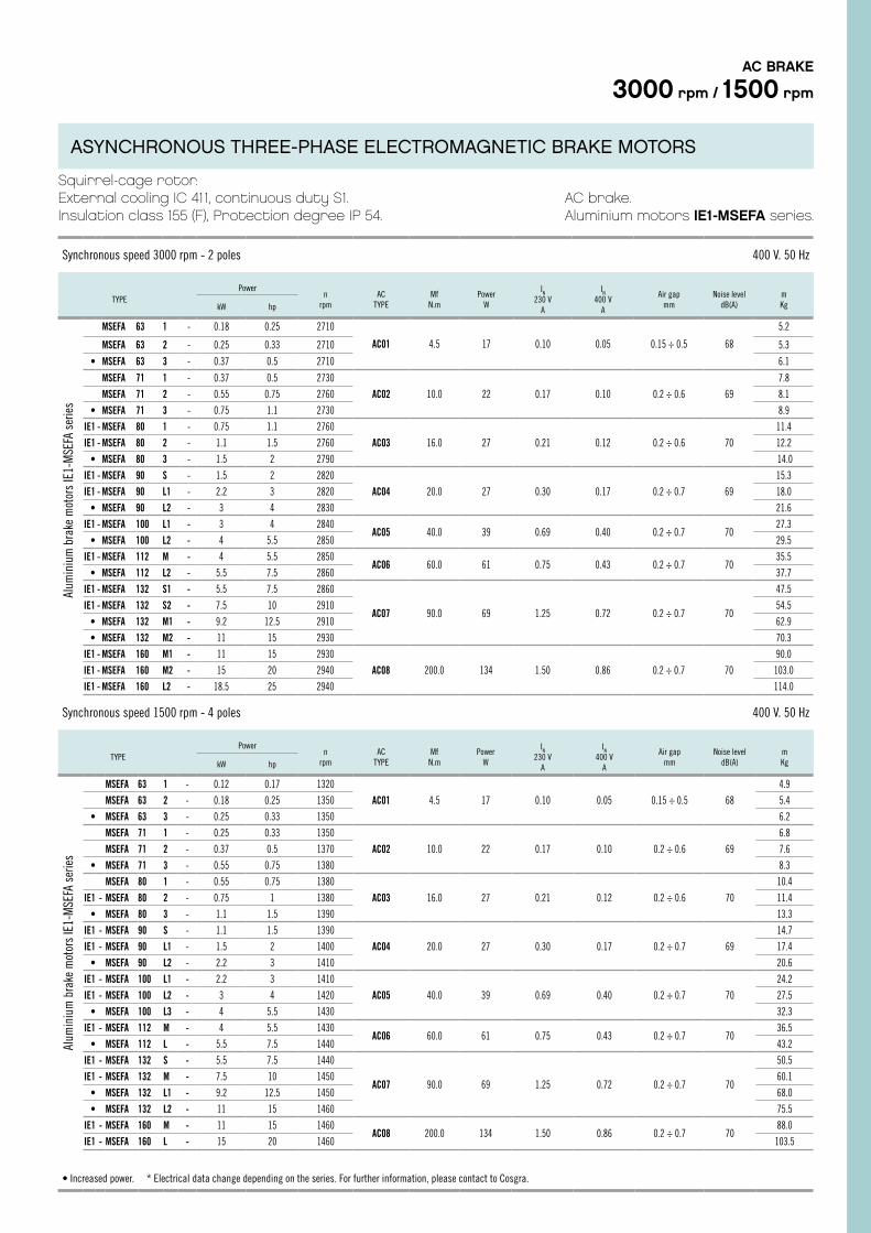
Squirrel-cage rotor.External cooling IC 411, continuous duty S1.Insulation class 155 (F), Protection degree IP 54.
AC brake.Aluminium motors IE1-MSEFA series.
Synchronous speed 1500 rpm - 4 poles 400 V. 50 Hz
TYPEPower
nrpm
ACTYPE
MfN.m
PowerW
IN
230 VA
IN
400 VA
Air gap mm
Noise leveldB(A)
mKgkW hp
MSEFA 63 1 - 0.12 0.17 1320
AC01 4.5 17 0.10 0.05 0.15 ÷ 0.5 68
4.9
MSEFA 63 2 - 0.18 0.25 1350 5.4
• MSEFA 63 3 - 0.25 0.33 1350 6.2
MSEFA 71 1 - 0.25 0.33 1350
AC02 10.0 22 0.17 0.10 0.2 ÷ 0.6 69
6.8
MSEFA 71 2 - 0.37 0.5 1370 7.6
• MSEFA 71 3 - 0.55 0.75 1380 8.3
MSEFA 80 1 - 0.55 0.75 1380
AC03 16.0 27 0.21 0.12 0.2 ÷ 0.6 70
10.4
IE1 - MSEFA 80 2 - 0.75 1 1380 11.4
• MSEFA 80 3 - 1.1 1.5 1390 13.3
IE1 - MSEFA 90 S - 1.1 1.5 1390
AC04 20.0 27 0.30 0.17 0.2 ÷ 0.7 69
14.7
IE1 - MSEFA 90 L1 - 1.5 2 1400 17.4
• MSEFA 90 L2 - 2.2 3 1410 20.6
IE1 - MSEFA 100 L1 - 2.2 3 1410
AC05 40.0 39 0.69 0.40 0.2 ÷ 0.7 70
24.2
IE1 - MSEFA 100 L2 - 3 4 1420 27.5
• MSEFA 100 L3 - 4 5.5 1430 32.3
IE1 - MSEFA 112 M - 4 5.5 1430AC06 60.0 61 0.75 0.43 0.2 ÷ 0.7 70
36.5
• MSEFA 112 L - 5.5 7.5 1440 43.2
IE1 - MSEFA 132 S - 5.5 7.5 1440
AC07 90.0 69 1.25 0.72 0.2 ÷ 0.7 70
50.5
IE1 - MSEFA 132 M - 7.5 10 1450 60.1
• MSEFA 132 L1 - 9.2 12.5 1450 68.0
• MSEFA 132 L2 - 11 15 1460 75.5
IE1 - MSEFA 160 M - 11 15 1460AC08 200.0 134 1.50 0.86 0.2 ÷ 0.7 70
88.0
IE1 - MSEFA 160 L - 15 20 1460 103.5
• Increased power. * Electrical data change depending on the series. For further information, please contact to Cosgra.
Synchronous speed 3000 rpm - 2 poles 400 V. 50 Hz
TYPEPower
nrpm
ACTYPE
MfN.m
PowerW
IN
230 VA
IN
400 VA
Air gap mm
Noise leveldB(A)
mKgkW hp
MSEFA 63 1 - 0.18 0.25 2710
AC01 4.5 17 0.10 0.05 0.15 ÷ 0.5
89
5.2
MSEFA 63 2 - 0.25 0.33 2710 5.3
• MSEFA 63 3 - 0.37 0.5 2710 6.1
MSEFA 71 1 - 0.37 0.5 2730
AC02 10.0 22 0.17 0.10 0.2 ÷ 0.6 69
7.8
MSEFA 71 2 - 0.55 0.75 2760 8.1
• MSEFA 71 3 - 0.75 1.1 2730 8.9
IE1 - MSEFA 80 1 - 0.75 1.1 2760
AC03 16.0 27 0.21 0.12 0.2 ÷ 0.6 70
11.4
IE1 - MSEFA 80 2 - 1.1 1.5 2760 12.2
• MSEFA 80 3 - 1.5 2 2790 14.0
IE1 - MSEFA 90 S - 1.5 2 2820
AC04 20.0 27 0.30 0.17 0.2 ÷ 0.7 69
15.3
IE1 - MSEFA 90 L1 - 2.2 3 2820 18.0
• MSEFA 90 L2 - 3 4 2830 21.6
IE1 - MSEFA 100 L1 - 3 4 2840AC05 40.0 39 0.69 0.40 0.2 ÷ 0.7 70
27.3
• MSEFA 100 L2 - 4 5.5 2850 29.5
IE1 - MSEFA 112 M - 4 5.5 2850AC06 60.0 61 0.75 0.43 0.2 ÷ 0.7 70
35.5
• MSEFA 112 L2 - 5.5 7.5 2860 37.7
IE1 - MSEFA 132 S1 - 5.5 7.5 2860
AC07 90.0 69 1.25 0.72 0.2 ÷ 0.7 70
47.5
IE1 - MSEFA 132 S2 - 7.5 10 2910 54.5
• MSEFA 132 M1 - 9.2 12.5 2910 62.9
• MSEFA 132 M2 - 11 15 2930 70.3
IE1 - MSEFA 160 M1 - 11 15 2930
AC08 200.0 134 1.50 0.86 0.2 ÷ 0.7 70
90.0
IE1 - MSEFA 160 M2 - 15 20 2940 103.0
IE1 - MSEFA 160 L2 - 18.5 25 2940 114.0
AC BRAKE
3000 rpm / 1500 rpm
Alum
iniu
m b
rake
mot
ors
IE1-
MSE
FA s
erie
sAl
umin
ium
bra
ke m
otor
s IE
1-M
SEFA
ser
ies
ASYNCHRONOUS THREE-PHASE ELECTROMAGNETIC BRAKE MOTORS
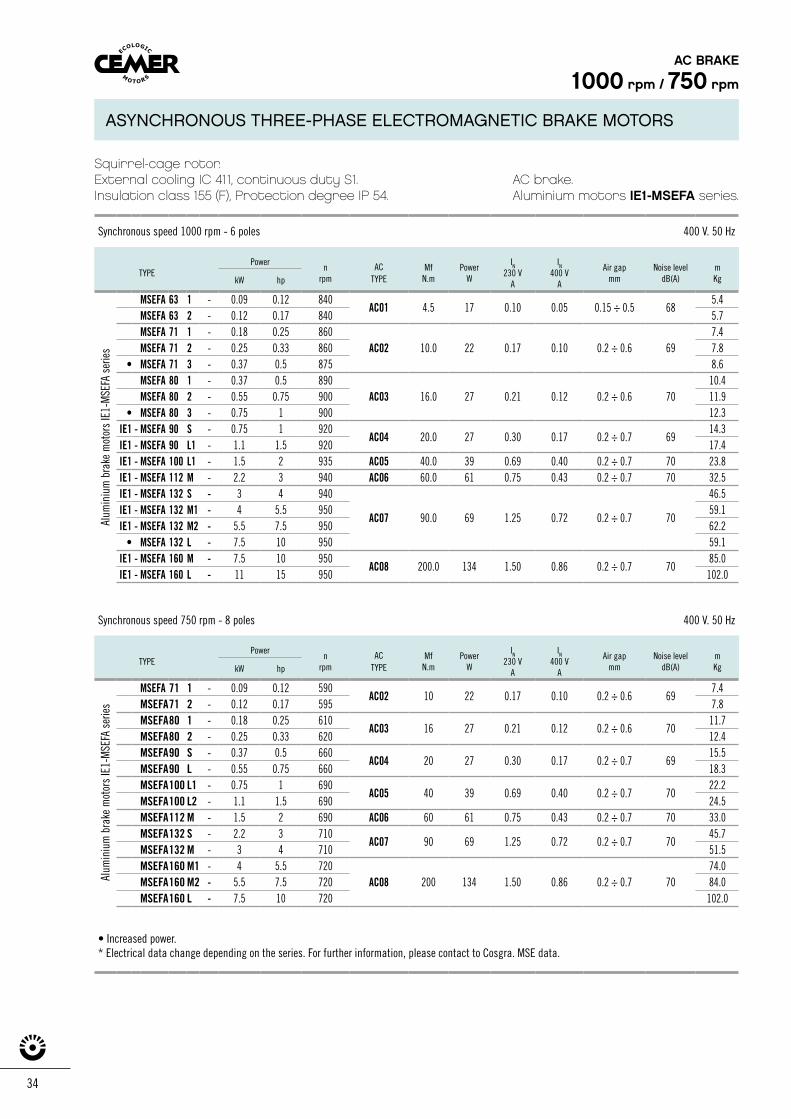
34
Squirrel-cage rotor. External cooling IC 411, continuous duty S1.Insulation class 155 (F), Protection degree IP 54.
AC brake.Aluminium motors IE1-MSEFA series.
Synchronous speed 1000 rpm - 6 poles 400 V. 50 Hz
TYPEPower
nrpm
AC TYPE
MfN.m
Power W
IN
230 VA
IN
400 VA
Air gap mm
Noise level dB(A)
mKgkW hp
MSEFA 63 1 - 0.09 0.12 840AC01 4.5 17 0.10 0.05 0.15 ÷ 0.5 68
5.4MSEFA 63 2 - 0.12 0.17 840 5.7MSEFA 71 1 - 0.18 0.25 860
AC02 10.0 22 0.17 0.10 0.2 ÷ 0.6 697.4
MSEFA 71 2 - 0.25 0.33 860 7.8• MSEFA 71 3 - 0.37 0.5 875 8.6
MSEFA 80 1 - 0.37 0.5 890AC03 16.0 27 0.21 0.12 0.2 ÷ 0.6 70
10.4MSEFA 80 2 - 0.55 0.75 900 11.9
• MSEFA 80 3 - 0.75 1 900 12.3IE1 - MSEFA 90 S - 0.75 1 920
AC04 20.0 27 0.30 0.17 0.2 ÷ 0.7 6914.3
IE1 - MSEFA 90 L1 - 1.1 1.5 920 17.4IE1 - MSEFA 100 L1 - 1.5 2 935 AC05 40.0 39 0.69 0.40 0.2 ÷ 0.7 70 23.8IE1 - MSEFA 112 M - 2.2 3 940 AC06 60.0 61 0.75 0.43 0.2 ÷ 0.7 70 32.5IE1 - MSEFA 132 S - 3 4 940
AC07 90.0 69 1.25 0.72 0.2 ÷ 0.7 70
46.5IE1 - MSEFA 132 M1 - 4 5.5 950 59.1IE1 - MSEFA 132 M2 - 5.5 7.5 950 62.2
• MSEFA 132 L - 7.5 10 950 59.1IE1 - MSEFA 160 M - 7.5 10 950
AC08 200.0 134 1.50 0.86 0.2 ÷ 0.7 7085.0
IE1 - MSEFA 160 L - 11 15 950 102.0
Synchronous speed 750 rpm - 8 poles 400 V. 50 Hz
TYPEPower
nrpm
AC TYPE
MfN.m
PowerW
IN
230 VA
IN
400 VA
Air gapmm
Noise level dB(A)
mKgkW hp
MSEFA 71 1 - 0.09 0.12 590AC02 10 22 0.17 0.10 0.2 ÷ 0.6 69
7.4MSEFA71 2 - 0.12 0.17 595 7.8MSEFA80 1 - 0.18 0.25 610
AC03 16 27 0.21 0.12 0.2 ÷ 0.6 7011.7
MSEFA80 2 - 0.25 0.33 620 12.4MSEFA90 S - 0.37 0.5 660
AC04 20 27 0.30 0.17 0.2 ÷ 0.7 6915.5
MSEFA90 L - 0.55 0.75 660 18.3MSEFA100 L1 - 0.75 1 690
AC05 40 39 0.69 0.40 0.2 ÷ 0.7 7022.2
MSEFA100 L2 - 1.1 1.5 690 24.5MSEFA112 M - 1.5 2 690 AC06 60 61 0.75 0.43 0.2 ÷ 0.7 70 33.0MSEFA132 S - 2.2 3 710
AC07 90 69 1.25 0.72 0.2 ÷ 0.7 7045.7
MSEFA132 M - 3 4 710 51.5MSEFA160 M1 - 4 5.5 720 74.0MSEFA160 M2 - 5.5 7.5 720 AC08 200 134 1.50 0.86 0.2 ÷ 0.7 70 84.0MSEFA160 L - 7.5 10 720 102.0
• Increased power.* Electrical data change depending on the series. For further information, please contact to Cosgra. MSE data.
AC BRAKE
1000 rpm / 750 rpmAl
umin
ium
bra
ke m
otor
s IE
1-M
SEFA
ser
ies
Alum
iniu
m b
rake
mot
ors
IE1-
MSE
FA s
erie
s
ASYNCHRONOUS THREE-PHASE ELECTROMAGNETIC BRAKE MOTORS
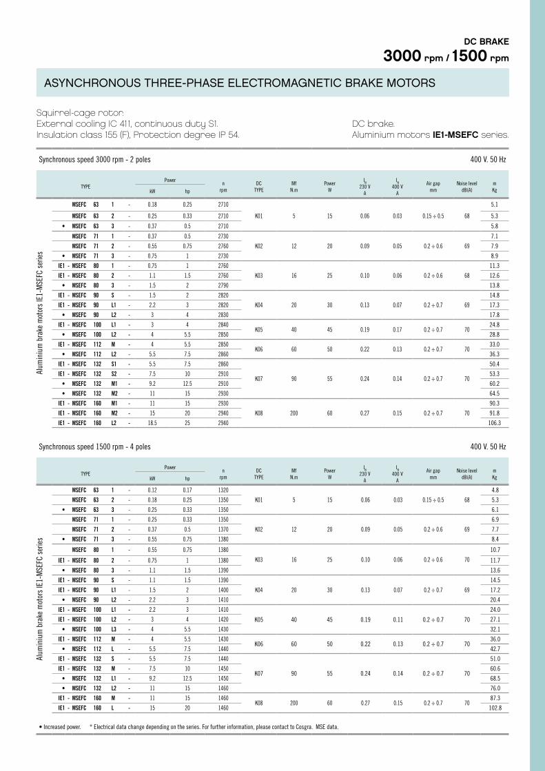
Squirrel-cage rotor.External cooling IC 411, continuous duty S1.Insulation class 155 (F), Protection degree IP 54.
DC brake.Aluminium motors IE1-MSEFC series.
Synchronous speed 3000 rpm - 2 poles 400 V. 50 Hz
TYPEPower
nrpm
DC TYPE
MfN.m
Power W
IN
230 VA
IN
400 VA
Air gapmm
Noise leveldB(A)
mKgkW hp
MSEFC 63 1 - 0.18 0.25 2710 5.1
MSEFC 63 2 - 0.25 0.33 2710 K01 5 15 0.06 0.03 0.15 ÷ 0.5 68 5.3
• MSEFC 63 3 - 0.37 0.5 2710 5.8
MSEFC 71 1 - 0.37 0.5 2730 7.1
MSEFC 71 2 - 0.55 0.75 2760 K02 12 20 0.09 0.05 0.2 ÷ 0.6 69 7.9
• MSEFC 71 3 - 0.75 1 2730 8.9
IE1 - MSEFC 80 1 - 0.75 1 2760 11.3
IE1 - MSEFC 80 2 - 1.1 1.5 2760 K03 16 25 0.10 0.06 0.2 ÷ 0.6 68 12.6
• MSEFC 80 3 - 1.5 2 2790 13.8
IE1 - MSEFC 90 S - 1.5 2 2820 14.8
IE1 - MSEFC 90 L1 - 2.2 3 2820 K04 20 30 0.13 0.07 0.2 ÷ 0.7 69 17.3
• MSEFC 90 L2 - 3 4 2830 17.8
IE1 - MSEFC 100 L1 - 3 4 2840K05 40 45 0.19 0.17 0.2 ÷ 0.7 70
24.8
• MSEFC 100 L2 - 4 5.5 2850 28.8
IE1 - MSEFC 112 M - 4 5.5 2850K06 60 50 0.22 0.13 0.2 ÷ 0.7 70
33.0
• MSEFC 112 L2 - 5.5 7.5 2860 36.3
IE1 - MSEFC 132 S1 - 5.5 7.5 2860
K07 90 55 0.24 0.14 0.2 ÷ 0.7 70
50.4
IE1 - MSEFC 132 S2 - 7.5 10 2910 53.3
• MSEFC 132 M1 - 9.2 12.5 2910 60.2
• MSEFC 132 M2 - 11 15 2930 64.5
IE1 - MSEFC 160 M1 - 11 15 2930 90.3
IE1 - MSEFC 160 M2 - 15 20 2940 K08 200 60 0.27 0.15 0.2 ÷ 0.7 70 91.8
IE1 - MSEFC 160 L2 - 18.5 25 2940 106.3
Synchronous speed 1500 rpm - 4 poles 400 V. 50 Hz
TYPEPower
nrpm
DC TYPE
MfN.m
PowerW
IN
230 VA
IN
400 VA
Air gapmm
Noise leveldB(A)
mKgkW hp
MSEFC 63 1 - 0.12 0.17 1320
K01 5 15 0.06 0.03 0.15 ÷ 0.5 68
4.8
MSEFC 63 2 - 0.18 0.25 1350 5.3
• MSEFC 63 3 - 0.25 0.33 1350 6.1
MSEFC 71 1 - 0.25 0.33 1350
K02 12 20 0.09 0.05 0.2 ÷ 0.6 69
6.9
MSEFC 71 2 - 0.37 0.5 1370 7.7
• MSEFC 71 3 - 0.55 0.75 1380 8.4
MSEFC 80 1 - 0.55 0.75 1380
K03 16 25 0.10 0.06 0.2 ÷ 0.6 70
10.7
IE1 - MSEFC 80 2 - 0.75 1 1380 11.7
• MSEFC 80 3 - 1.1 1.5 1390 13.6
IE1 - MSEFC 90 S - 1.1 1.5 1390
K04 20 30 0.13 0.07 0.2 ÷ 0.7 69
14.5
IE1 - MSEFC 90 L1 - 1.5 2 1400 17.2
• MSEFC 90 L2 - 2.2 3 1410 20.4
IE1 - MSEFC 100 L1 - 2.2 3 1410
K05 40 45 0.19 0.11 0.2 ÷ 0.7 70
24.0
IE1 - MSEFC 100 L2 - 3 4 1420 27.1
• MSEFC 100 L3 - 4 5.5 1430 32.1
IE1 - MSEFC 112 M - 4 5.5 1430K06 60 50 0.22 0.13 0.2 ÷ 0.7 70
36.0
• MSEFC 112 L - 5.5 7.5 1440 42.7
IE1 - MSEFC 132 S - 5.5 7.5 1440
K07 90 55 0.24 0.14 0.2 ÷ 0.7 70
51.0
IE1 - MSEFC 132 M - 7.5 10 1450 60.6
• MSEFC 132 L1 - 9.2 12.5 1450 68.5
• MSEFC 132 L2 - 11 15 1460 76.0
IE1 - MSEFC 160 M - 11 15 1460K08 200 60 0.27 0.15 0.2 ÷ 0.7 70
87.3
IE1 - MSEFC 160 L - 15 20 1460 102.8
• Increased power. * Electrical data change depending on the series. For further information, please contact to Cosgra. MSE data.
DC BRAKE
3000 rpm / 1500 rpm
Alum
iniu
m b
rake
mot
ors
IE1-
MSE
FC s
erie
sAl
umin
ium
bra
ke m
otor
s IE
1-M
SEFC
ser
ies
ASYNCHRONOUS THREE-PHASE ELECTROMAGNETIC BRAKE MOTORS
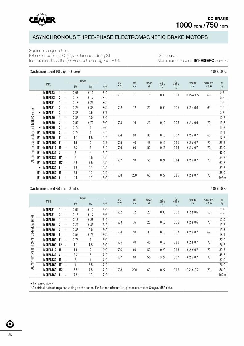
36
Squirrel-cage rotor. External cooling IC 411, continuous duty S1.Insulation class 155 (F), Protection degree IP 54.
DC brake.Aluminium motors IE1-MSEFC series.
Synchronous speed 1000 rpm - 6 poles 400 V. 50 Hz
TYPEPower
nrpm
DCTYPE
MfN.m
PowerW
IN
230 VA
IN
400 VA
Air gapmm
Noise leveldB(A)
mKgkW hp
MSEFC63 1 - 0.09 0.12 840K01 5 15 0.06 0.03 0.15 ÷ 0.5 68
5.3 MSEFC63 2 - 0.12 0.17 840 5.6 MSEFC71 1 - 0.18 0.25 860
20 0.09 0.05 7.5
MSEFC71 2 - 0.25 0.33 860 K02 12 0.2 ÷ 0.6 69 7.9 • MSEFC71 3 - 0.37 0.5 875 8.7
MSEFC80 1 - 0.37 0.5 89025 0.10 0.06
10.7 MSEFC80 2 - 0.55 0.75 900 K03 16 0.2 ÷ 0.6 70 12.2
• MSEFC80 3 - 0.75 1 900 12.6 IE1 - MSEFC90 S - 0.75 1 920
K04 20 30 0.13 0.07 0.2 ÷ 0.7 69 14.1
IE1 - MSEFC90 L1 - 1.1 1.5 920 17.2 IE1 - MSEFC100 L1 - 1.5 2 935 K05 40 45 0.19 0.11 0.2 ÷ 0.7 70 23.6 IE1 - MSEFC112 M - 2.2 3 940 K06 60 50 0.22 0.13 0.2 ÷ 0.7 70 32.0 IE1 - MSEFC132 S - 3 4 940
K07 90 55 0.24 0.14 0.2 ÷ 0.7 70
47.0 IE1 - MSEFC132 M1 - 4 5.5 950 59.6 IE1 - MSEFC132 M2 - 5.5 7.5 950 62.7
• MSEFC132 L - 7.5 10 950 59.6 IE1 - MSEFC160 M - 7.5 10 950
K08 200 60 0.27 0.15 0.2 ÷ 0.7 70 85.0
IE1 - MSEFC160 L - 11 15 950 102.0
Synchronous speed 750 rpm - 8 poles 400 V. 50 Hz
TYPEPower
nrpm
DCTYPE
MfN.m
PowerW
IN
230 VA
IN
400 VA
Air gapmm
Noise leveldB(A)
mKgkW hp
MSEFC71 1 - 0.09 0.12 590K02 12 20 0.09 0.05 0.2 ÷ 0.6 69
7.5 MSEFC71 2 - 0.12 0.17 595 7.9 MSEFC80 1 - 0.18 0.25 610
K03 16 25 0.10 0'06 0.2 ÷ 0.6 70 12.0
MSEFC80 2 - 0.25 0.33 620 12.7 MSEFC90 S - 0.37 0.5 660
K04 20 30 0.13 0.07 0.2 ÷ 0.7 69 15.3
MSEFC90 L - 0.55 0.75 660 18.1 MSEFC100 L1 - 0.75 1 690
K05 40 45 0.19 0.11 0.2 ÷ 0.7 70 22.0
MSEFC100 L2 - 1.1 1.5 690 24.3 MSEFC112 M - 1.5 2 690 K06 60 50 0.22 0.13 0.2 ÷ 0.7 70 32.5 MSEFC132 S - 2.2 3 710
K07 90 55 0.24 0.14 0.2 ÷ 0.7 70 46.2
MSEFC132 M - 3 4 710 52.0 MSEFC160 M1 - 4 5.5 720
K08 200 60 0.27 0.15 0.2 ÷ 0.7 70 74.0
MSEFC160 M2 - 5.5 7.5 720 84.0 MSEFC160 L - 7.5 10 720 102.0
• Increased power.* Electrical data change depending on the series. For further information, please contact to Cosgra. MSE data.
DC BRAKE
1000 rpm / 750 rpmAl
umin
ium
bra
ke m
otor
s IE
1-M
SEFA
ser
ies
Alum
iniu
m b
rake
mot
ors
IE1-
MSE
FC s
erie
s
ASYNCHRONOUS THREE-PHASE ELECTROMAGNETIC BRAKE MOTORS
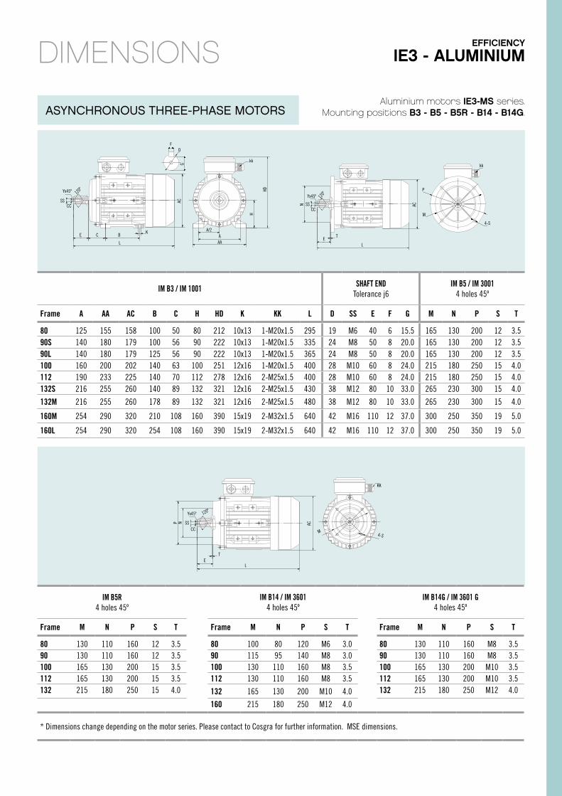
N
ET
AC
KK
4-S
P
L
MCC
Yx45º 120º
SS
Aluminium motors IE3-MS series.Mounting positions B3 - B5 - B5R - B14 - B14G.
DIMENSIONS
IM B3 / IM 1001 SHAFT ENDTolerance j6
IM B5 / IM 30014 holes 45º
Frame A AA AC B C H HD K KK L D SS E F G M N P S T
80 125 155 158 100 50 80 212 10x13 1-M20x1.5 295 19 M6 40 6 15.5 165 130 200 12 3.590S 140 180 179 100 56 90 222 10x13 1-M20x1.5 335 24 M8 50 8 20.0 165 130 200 12 3.590L 140 180 179 125 56 90 222 10x13 1-M20x1.5 365 24 M8 50 8 20.0 165 130 200 12 3.5100 160 200 202 140 63 100 251 12x16 1-M20x1.5 400 28 M10 60 8 24.0 215 180 250 15 4.0112 190 233 225 140 70 112 278 12x16 2-M25x1.5 400 28 M10 60 8 24.0 215 180 250 15 4.0132S 216 255 260 140 89 132 321 12x16 2-M25x1.5 430 38 M12 80 10 33.0 265 230 300 15 4.0
132M 216 255 260 178 89 132 321 12x16 2-M25x1.5 480 38 M12 80 10 33.0 265 230 300 15 4.0
160M 254 290 320 210 108 160 390 15x19 2-M32x1.5 640 42 M16 110 12 37.0 300 250 350 19 5.0
160L 254 290 320 254 108 160 390 15x19 2-M32x1.5 640 42 M16 110 12 37.0 300 250 350 19 5.0
IM B5R4 holes 45º
IM B14 / IM 36014 holes 45º
IM B14G / IM 3601 G4 holes 45º
Frame M N P S T Frame M N P S T Frame M N P S T
80 130 110 160 12 3.5 80 100 80 120 M6 3.0 80 130 110 160 M8 3.590 130 110 160 12 3.5 90 115 95 140 M8 3.0 90 130 110 160 M8 3.5100 165 130 200 15 3.5 100 130 110 160 M8 3.5 100 165 130 200 M10 3.5112 165 130 200 15 3.5 112 130 110 160 M8 3.5 112 165 130 200 M10 3.5132 215 180 250 15 4.0 132 165 130 200 M10 4.0 132 215 180 250 M12 4.0
160 215 180 250 M12 4.0
* Dimensions change depending on the motor series. Please contact to Cosgra for further information. MSE dimensions.
FD
kk
A/2A
AAL
E C K
CCSS
Yx45º 120º
GAC
HD
HL
N AC
ET
P
kk
4-S
MCC
SS
Yx45º 120º
B
EFFICIENCY
IE3 - ALUMINIUM
ASYNCHRONOUS THREE-PHASE MOTORS
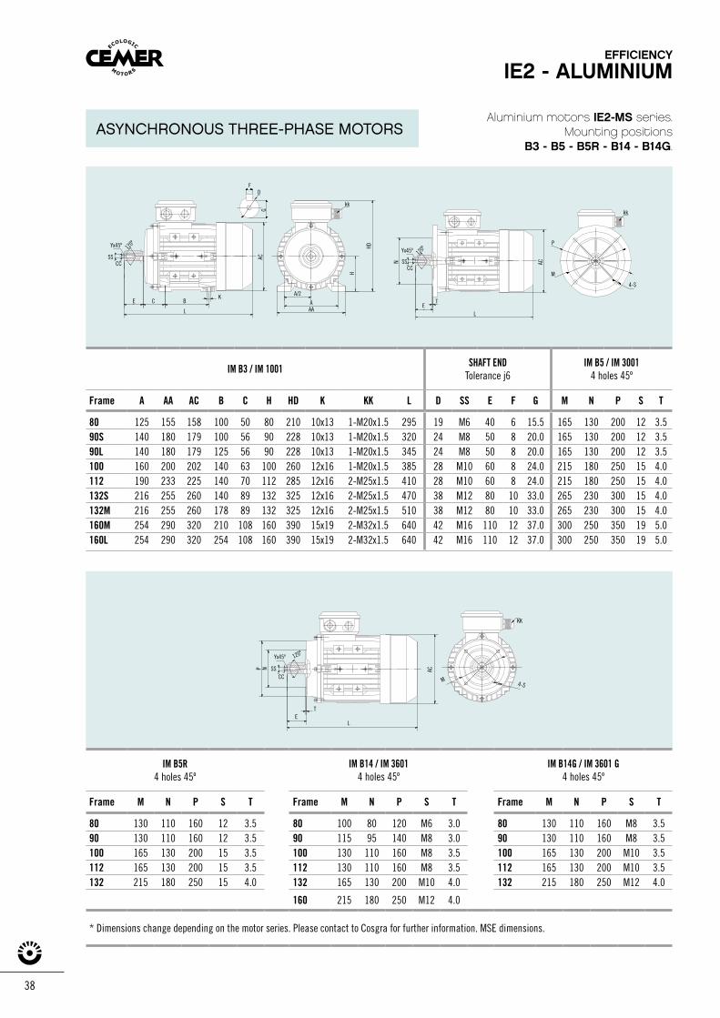
38
N
ET
AC
KK
4-S
P
L
MCC
Yx45º 120º
SS
Aluminium motors IE2-MS series.Mounting positions
B3 - B5 - B5R - B14 - B14G.
IM B3 / IM 1001 SHAFT ENDTolerance j6
IM B5 / IM 30014 holes 45º
Frame A AA AC B C H HD K KK L D SS E F G M N P S T
80 125 155 158 100 50 80 210 10x13 1-M20x1.5 295 19 M6 40 6 15.5 165 130 200 12 3.590S 140 180 179 100 56 90 228 10x13 1-M20x1.5 320 24 M8 50 8 20.0 165 130 200 12 3.590L 140 180 179 125 56 90 228 10x13 1-M20x1.5 345 24 M8 50 8 20.0 165 130 200 12 3.5100 160 200 202 140 63 100 260 12x16 1-M20x1.5 385 28 M10 60 8 24.0 215 180 250 15 4.0112 190 233 225 140 70 112 285 12x16 2-M25x1.5 410 28 M10 60 8 24.0 215 180 250 15 4.0132S 216 255 260 140 89 132 325 12x16 2-M25x1.5 470 38 M12 80 10 33.0 265 230 300 15 4.0132M 216 255 260 178 89 132 325 12x16 2-M25x1.5 510 38 M12 80 10 33.0 265 230 300 15 4.0160M 254 290 320 210 108 160 390 15x19 2-M32x1.5 640 42 M16 110 12 37.0 300 250 350 19 5.0160L 254 290 320 254 108 160 390 15x19 2-M32x1.5 640 42 M16 110 12 37.0 300 250 350 19 5.0
IM B5R4 holes 45º
IM B14 / IM 36014 holes 45º
IM B14G / IM 3601 G4 holes 45º
Frame M N P S T Frame M N P S T Frame M N P S T
80 130 110 160 12 3.5 80 100 80 120 M6 3.0 80 130 110 160 M8 3.590 130 110 160 12 3.5 90 115 95 140 M8 3.0 90 130 110 160 M8 3.5100 165 130 200 15 3.5 100 130 110 160 M8 3.5 100 165 130 200 M10 3.5112 165 130 200 15 3.5 112 130 110 160 M8 3.5 112 165 130 200 M10 3.5132 215 180 250 15 4.0 132 165 130 200 M10 4.0 132 215 180 250 M12 4.0
160 215 180 250 M12 4.0
* Dimensions change depending on the motor series. Please contact to Cosgra for further information. MSE dimensions.
F
kk
D
K
L
BA/2
AAA
CE
CCSS
Yx45º 120º
GAC
HD
H
LE
T
kk
P
M
4-S
N AC
CC
Yx45º 120º
SS
EFFICIENCY
IE2 - ALUMINIUM
ASYNCHRONOUS THREE-PHASE MOTORS
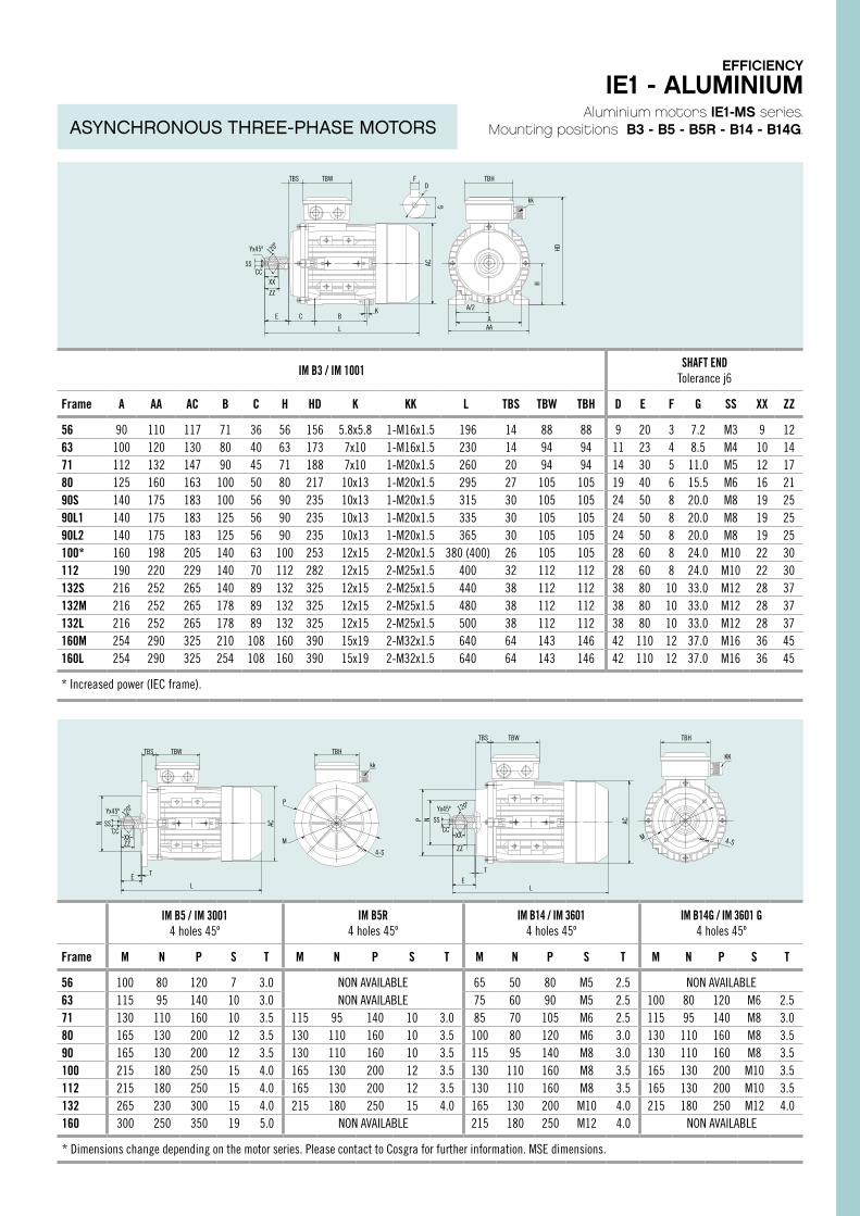
IM B5R4 holes 45º
IM B14 / IM 36014 holes 45º
IM B14G / IM 3601 G4 holes 45º
Frame M N P S T Frame M N P S T Frame M N P S T
80 130 110 160 12 3.5 80 100 80 120 M6 3.0 80 130 110 160 M8 3.590 130 110 160 12 3.5 90 115 95 140 M8 3.0 90 130 110 160 M8 3.5100 165 130 200 15 3.5 100 130 110 160 M8 3.5 100 165 130 200 M10 3.5112 165 130 200 15 3.5 112 130 110 160 M8 3.5 112 165 130 200 M10 3.5132 215 180 250 15 4.0 132 165 130 200 M10 4.0 132 215 180 250 M12 4.0
160 215 180 250 M12 4.0
* Dimensions change depending on the motor series. Please contact to Cosgra for further information. MSE dimensions.
Aluminium motors IE1-MS series.Mounting positions B3 - B5 - B5R - B14 - B14G.
IM B3 / IM 1001SHAFT END
Tolerance j6
Frame A AA AC B C H HD K KK L TBS TBW TBH D E F G SS XX ZZ
56 90 110 117 71 36 56 156 5.8x5.8 1-M16x1.5 196 14 88 88 9 20 3 7.2 M3 9 1263 100 120 130 80 40 63 173 7x10 1-M16x1.5 230 14 94 94 11 23 4 8.5 M4 10 1471 112 132 147 90 45 71 188 7x10 1-M20x1.5 260 20 94 94 14 30 5 11.0 M5 12 1780 125 160 163 100 50 80 217 10x13 1-M20x1.5 295 27 105 105 19 40 6 15.5 M6 16 2190S 140 175 183 100 56 90 235 10x13 1-M20x1.5 315 30 105 105 24 50 8 20.0 M8 19 2590L1 140 175 183 125 56 90 235 10x13 1-M20x1.5 335 30 105 105 24 50 8 20.0 M8 19 2590L2 140 175 183 125 56 90 235 10x13 1-M20x1.5 365 30 105 105 24 50 8 20.0 M8 19 25100* 160 198 205 140 63 100 253 12x15 2-M20x1.5 380 (400) 26 105 105 28 60 8 24.0 M10 22 30112 190 220 229 140 70 112 282 12x15 2-M25x1.5 400 32 112 112 28 60 8 24.0 M10 22 30132S 216 252 265 140 89 132 325 12x15 2-M25x1.5 440 38 112 112 38 80 10 33.0 M12 28 37132M 216 252 265 178 89 132 325 12x15 2-M25x1.5 480 38 112 112 38 80 10 33.0 M12 28 37132L 216 252 265 178 89 132 325 12x15 2-M25x1.5 500 38 112 112 38 80 10 33.0 M12 28 37160M 254 290 325 210 108 160 390 15x19 2-M32x1.5 640 64 143 146 42 110 12 37.0 M16 36 45160L 254 290 325 254 108 160 390 15x19 2-M32x1.5 640 64 143 146 42 110 12 37.0 M16 36 45
* Increased power (IEC frame).
IM B5 / IM 30014 holes 45º
IM B5R4 holes 45º
IM B14 / IM 36014 holes 45º
IM B14G / IM 3601 G4 holes 45º
Frame M N P S T M N P S T M N P S T M N P S T
56 100 80 120 7 3.0 NON AVAILABLE 65 50 80 M5 2.5 NON AVAILABLE63 115 95 140 10 3.0 NON AVAILABLE 75 60 90 M5 2.5 100 80 120 M6 2.571 130 110 160 10 3.5 115 95 140 10 3.0 85 70 105 M6 2.5 115 95 140 M8 3.080 165 130 200 12 3.5 130 110 160 10 3.5 100 80 120 M6 3.0 130 110 160 M8 3.590 165 130 200 12 3.5 130 110 160 10 3.5 115 95 140 M8 3.0 130 110 160 M8 3.5100 215 180 250 15 4.0 165 130 200 12 3.5 130 110 160 M8 3.5 165 130 200 M10 3.5112 215 180 250 15 4.0 165 130 200 12 3.5 130 110 160 M8 3.5 165 130 200 M10 3.5132 265 230 300 15 4.0 215 180 250 15 4.0 165 130 200 M10 4.0 215 180 250 M12 4.0160 300 250 350 19 5.0 NON AVAILABLE 215 180 250 M12 4.0 NON AVAILABLE
* Dimensions change depending on the motor series. Please contact to Cosgra for further information. MSE dimensions.
L
ZZ
XXCC
SS
Yx45º 120º
E C BK
AC
HD
H
G
TBS FD
kk
TBW TBH
A/2
A AA
TBW TBH
P
M
4-S
kk
LE T
ZZ
CCSS
Yx45º 120º
XX
TBS
N AC
N
ET
AC
KK
4-S
P
L
MCC
Yx45º 120º
SS
ZZ
XX
TBS TBW TBH
EFFICIENCY
IE1 - ALUMINIUM
ASYNCHRONOUS THREE-PHASE MOTORS
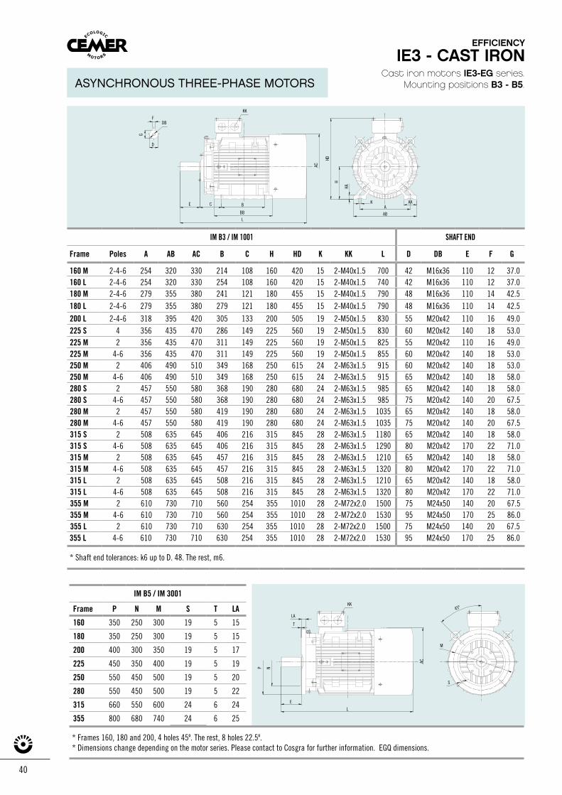
40
Cast iron motors IE3-EG series.Mounting positions B3 - B5.
IM B5 / IM 3001
Frame P N M S T LA
160 350 250 300 19 5 15
180 350 250 300 19 5 15
200 400 300 350 19 5 17
225 450 350 400 19 5 19
250 550 450 500 19 5 20
280 550 450 500 19 5 22
315 660 550 600 24 6 24
355 800 680 740 24 6 25
E
L
N
S
45º
M
AC
KK
LA
T
P
L
F
DG
E C B
AC
K
AB
A
HD
HA
DB
KK
BB
AA
H
* Frames 160, 180 and 200, 4 holes 45º. The rest, 8 holes 22.5º.* Dimensions change depending on the motor series. Please contact to Cosgra for further information. EGQ dimensions.
EFFICIENCY
IE3 - CAST IRON
ASYNCHRONOUS THREE-PHASE MOTORS
IM B3 / IM 1001 SHAFT END
Frame Poles A AB AC B C H HD K KK L D DB E F G
160 M 2-4-6 254 320 330 214 108 160 420 15 2-M40x1.5 700 42 M16x36 110 12 37.0160 L 2-4-6 254 320 330 254 108 160 420 15 2-M40x1.5 740 42 M16x36 110 12 37.0180 M 2-4-6 279 355 380 241 121 180 455 15 2-M40x1.5 790 48 M16x36 110 14 42.5180 L 2-4-6 279 355 380 279 121 180 455 15 2-M40x1.5 790 48 M16x36 110 14 42.5
200 L 2-4-6 318 395 420 305 133 200 505 19 2-M50x1.5 830 55 M20x42 110 16 49.0225 S 4 356 435 470 286 149 225 560 19 2-M50x1.5 830 60 M20x42 140 18 53.0225 M 2 356 435 470 311 149 225 560 19 2-M50x1.5 825 55 M20x42 110 16 49.0225 M 4-6 356 435 470 311 149 225 560 19 2-M50x1.5 855 60 M20x42 140 18 53.0250 M 2 406 490 510 349 168 250 615 24 2-M63x1.5 915 60 M20x42 140 18 53.0250 M 4-6 406 490 510 349 168 250 615 24 2-M63x1.5 915 65 M20x42 140 18 58.0280 S 2 457 550 580 368 190 280 680 24 2-M63x1.5 985 65 M20x42 140 18 58.0280 S 4-6 457 550 580 368 190 280 680 24 2-M63x1.5 985 75 M20x42 140 20 67.5280 M 2 457 550 580 419 190 280 680 24 2-M63x1.5 1035 65 M20x42 140 18 58.0280 M 4-6 457 550 580 419 190 280 680 24 2-M63x1.5 1035 75 M20x42 140 20 67.5315 S 2 508 635 645 406 216 315 845 28 2-M63x1.5 1180 65 M20x42 140 18 58.0315 S 4-6 508 635 645 406 216 315 845 28 2-M63x1.5 1290 80 M20x42 170 22 71.0315 M 2 508 635 645 457 216 315 845 28 2-M63x1.5 1210 65 M20x42 140 18 58.0315 M 4-6 508 635 645 457 216 315 845 28 2-M63x1.5 1320 80 M20x42 170 22 71.0315 L 2 508 635 645 508 216 315 845 28 2-M63x1.5 1210 65 M20x42 140 18 58.0315 L 4-6 508 635 645 508 216 315 845 28 2-M63x1.5 1320 80 M20x42 170 22 71.0355 M 2 610 730 710 560 254 355 1010 28 2-M72x2.0 1500 75 M24x50 140 20 67.5355 M 4-6 610 730 710 560 254 355 1010 28 2-M72x2.0 1530 95 M24x50 170 25 86.0355 L 2 610 730 710 630 254 355 1010 28 2-M72x2.0 1500 75 M24x50 140 20 67.5355 L 4-6 610 730 710 630 254 355 1010 28 2-M72x2.0 1530 95 M24x50 170 25 86.0
* Shaft end tolerances: k6 up to D. 48. The rest, m6.
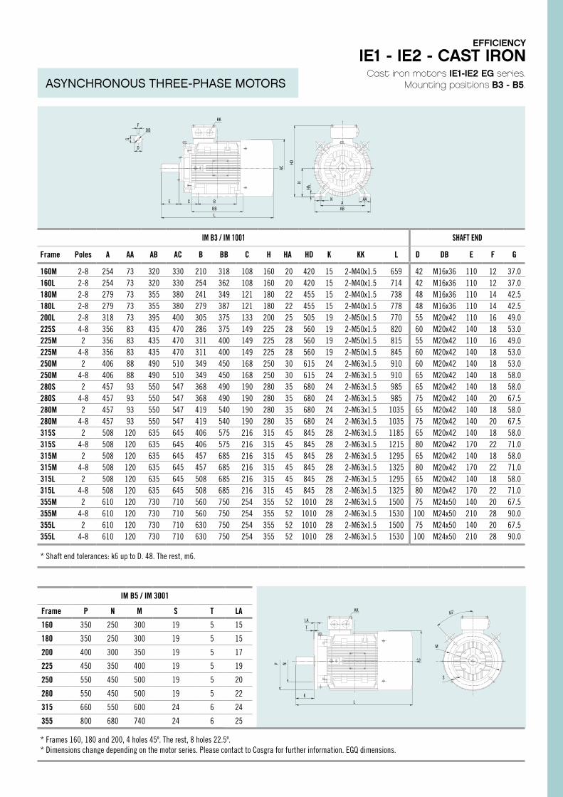
Cast iron motors IE1-IE2 EG series.Mounting positions B3 - B5.
IM B3 / IM 1001 SHAFT END
Frame Poles A AA AB AC B BB C H HA HD K KK L D DB E F G
160M 2-8 254 73 320 330 210 318 108 160 20 420 15 2-M40x1.5 659 42 M16x36 110 12 37.0160L 2-8 254 73 320 330 254 362 108 160 20 420 15 2-M40x1.5 714 42 M16x36 110 12 37.0180M 2-8 279 73 355 380 241 349 121 180 22 455 15 2-M40x1.5 738 48 M16x36 110 14 42.5180L 2-8 279 73 355 380 279 387 121 180 22 455 15 2-M40x1.5 778 48 M16x36 110 14 42.5200L 2-8 318 73 395 400 305 375 133 200 25 505 19 2-M50x1.5 770 55 M20x42 110 16 49.0225S 4-8 356 83 435 470 286 375 149 225 28 560 19 2-M50x1.5 820 60 M20x42 140 18 53.0225M 2 356 83 435 470 311 400 149 225 28 560 19 2-M50x1.5 815 55 M20x42 110 16 49.0225M 4-8 356 83 435 470 311 400 149 225 28 560 19 2-M50x1.5 845 60 M20x42 140 18 53.0250M 2 406 88 490 510 349 450 168 250 30 615 24 2-M63x1.5 910 60 M20x42 140 18 53.0250M 4-8 406 88 490 510 349 450 168 250 30 615 24 2-M63x1.5 910 65 M20x42 140 18 58.0280S 2 457 93 550 547 368 490 190 280 35 680 24 2-M63x1.5 985 65 M20x42 140 18 58.0280S 4-8 457 93 550 547 368 490 190 280 35 680 24 2-M63x1.5 985 75 M20x42 140 20 67.5280M 2 457 93 550 547 419 540 190 280 35 680 24 2-M63x1.5 1035 65 M20x42 140 18 58.0280M 4-8 457 93 550 547 419 540 190 280 35 680 24 2-M63x1.5 1035 75 M20x42 140 20 67.5315S 2 508 120 635 645 406 575 216 315 45 845 28 2-M63x1.5 1185 65 M20x42 140 18 58.0315S 4-8 508 120 635 645 406 575 216 315 45 845 28 2-M63x1.5 1215 80 M20x42 170 22 71.0315M 2 508 120 635 645 457 685 216 315 45 845 28 2-M63x1.5 1295 65 M20x42 140 18 58.0315M 4-8 508 120 635 645 457 685 216 315 45 845 28 2-M63x1.5 1325 80 M20x42 170 22 71.0315L 2 508 120 635 645 508 685 216 315 45 845 28 2-M63x1.5 1295 65 M20x42 140 18 58.0315L 4-8 508 120 635 645 508 685 216 315 45 845 28 2-M63x1.5 1325 80 M20x42 170 22 71.0355M 2 610 120 730 710 560 750 254 355 52 1010 28 2-M63x1.5 1500 75 M24x50 140 20 67.5355M 4-8 610 120 730 710 560 750 254 355 52 1010 28 2-M63x1.5 1530 100 M24x50 210 28 90.0355L 2 610 120 730 710 630 750 254 355 52 1010 28 2-M63x1.5 1500 75 M24x50 140 20 67.5355L 4-8 610 120 730 710 630 750 254 355 52 1010 28 2-M63x1.5 1530 100 M24x50 210 28 90.0
* Shaft end tolerances: k6 up to D. 48. The rest, m6.
IM B5 / IM 3001
Frame P N M S T LA
160 350 250 300 19 5 15
180 350 250 300 19 5 15
200 400 300 350 19 5 17
225 450 350 400 19 5 19
250 550 450 500 19 5 20
280 550 450 500 19 5 22
315 660 550 600 24 6 24
355 800 680 740 24 6 25
* Frames 160, 180 and 200, 4 holes 45º. The rest, 8 holes 22.5º. * Dimensions change depending on the motor series. Please contact to Cosgra for further information. EGQ dimensions.
KK
E C B
BB
KA
AB
AA
L
FDB
D
G
AC
HD
H
HA
KK
M
S
45º
LE
NP AC
LA
T
EFFICIENCY
IE1 - IE2 - CAST IRON
ASYNCHRONOUS THREE-PHASE MOTORS
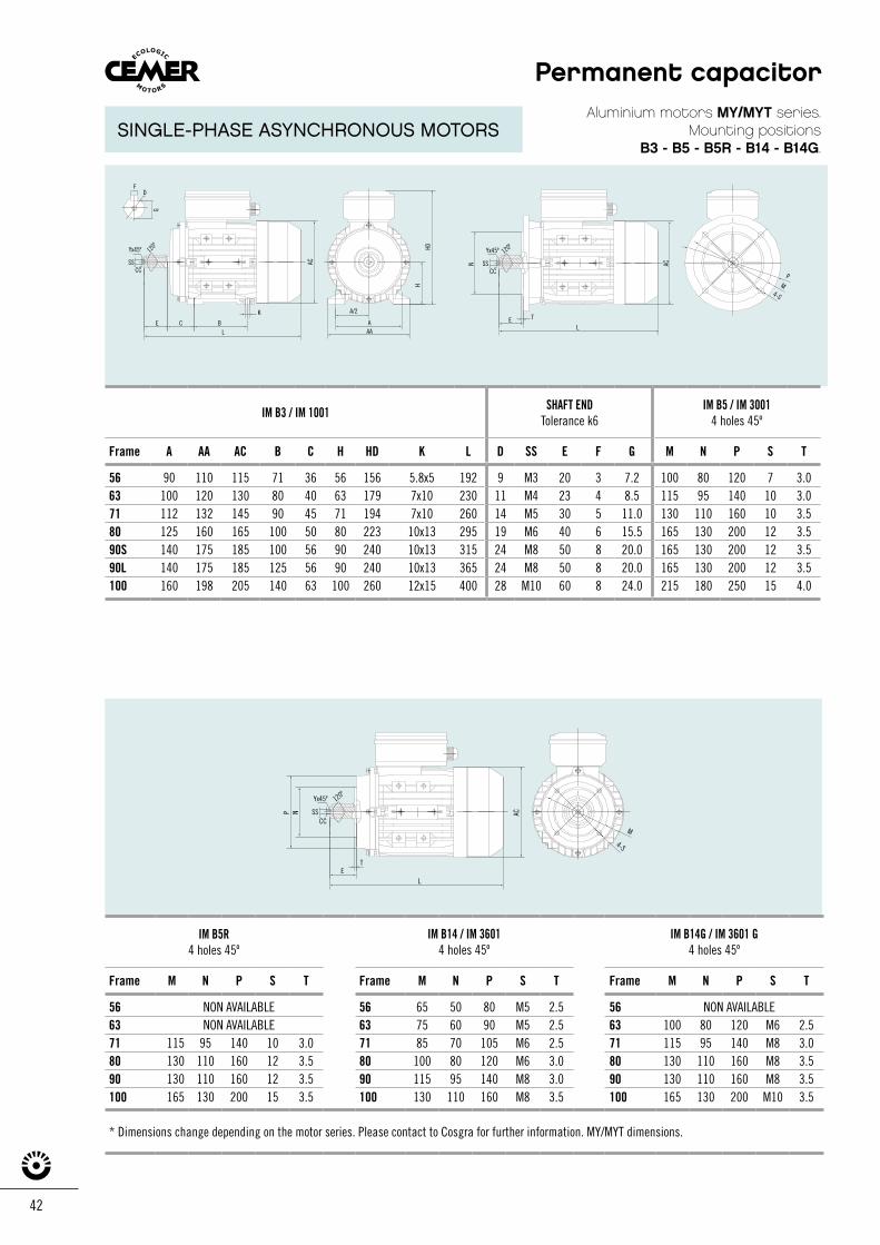
42
Aluminium motors MY/MYT series.Mounting positions
B3 - B5 - B5R - B14 - B14G.
IM B3 / IM 1001 SHAFT ENDTolerance k6
IM B5 / IM 30014 holes 45º
Frame A AA AC B C H HD K L D SS E F G M N P S T
56 90 110 115 71 36 56 156 5.8x5 192 9 M3 20 3 7.2 100 80 120 7 3.063 100 120 130 80 40 63 179 7x10 230 11 M4 23 4 8.5 115 95 140 10 3.071 112 132 145 90 45 71 194 7x10 260 14 M5 30 5 11.0 130 110 160 10 3.580 125 160 165 100 50 80 223 10x13 295 19 M6 40 6 15.5 165 130 200 12 3.590S 140 175 185 100 56 90 240 10x13 315 24 M8 50 8 20.0 165 130 200 12 3.590L 140 175 185 125 56 90 240 10x13 365 24 M8 50 8 20.0 165 130 200 12 3.5100 160 198 205 140 63 100 260 12x15 400 28 M10 60 8 24.0 215 180 250 15 4.0
IM B5R4 holes 45º
IM B14 / IM 36014 holes 45º
IM B14G / IM 3601 G4 holes 45º
Frame M N P S T Frame M N P S T Frame M N P S T
56 NON AVAILABLE 56 65 50 80 M5 2.5 56 NON AVAILABLE63 NON AVAILABLE 63 75 60 90 M5 2.5 63 100 80 120 M6 2.571 115 95 140 10 3.0 71 85 70 105 M6 2.5 71 115 95 140 M8 3.080 130 110 160 12 3.5 80 100 80 120 M6 3.0 80 130 110 160 M8 3.590 130 110 160 12 3.5 90 115 95 140 M8 3.0 90 130 110 160 M8 3.5100 165 130 200 15 3.5 100 130 110 160 M8 3.5 100 165 130 200 M10 3.5
* Dimensions change depending on the motor series. Please contact to Cosgra for further information. MY/MYT dimensions.
LE T
PM
4-S
CC
N ACSS
Yx45º 120º
LE
T
NP AC
M
4-S
CCSS
Yx45º 120º
L
KAC
BAA
H
HD
A
A/2
CE
FD
G
CCSS
Yx45º 120º
Permanent capacitor
SINGLE-PHASE ASYNCHRONOUS MOTORS
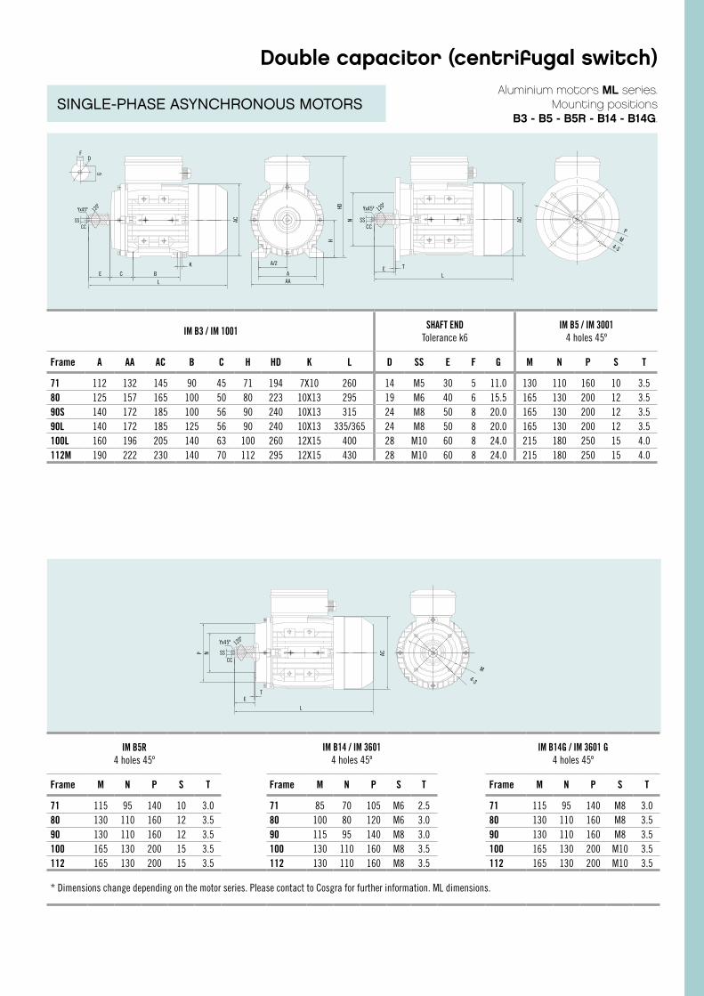
Aluminium motors ML series. Mounting positions
B3 - B5 - B5R - B14 - B14G.
IM B3 / IM 1001 SHAFT ENDTolerance k6
IM B5 / IM 30014 holes 45º
Frame A AA AC B C H HD K L D SS E F G M N P S T
71 112 132 145 90 45 71 194 7X10 260 14 M5 30 5 11.0 130 110 160 10 3.580 125 157 165 100 50 80 223 10X13 295 19 M6 40 6 15.5 165 130 200 12 3.590S 140 172 185 100 56 90 240 10X13 315 24 M8 50 8 20.0 165 130 200 12 3.590L 140 172 185 125 56 90 240 10X13 335/365 24 M8 50 8 20.0 165 130 200 12 3.5100L 160 196 205 140 63 100 260 12X15 400 28 M10 60 8 24.0 215 180 250 15 4.0112M 190 222 230 140 70 112 295 12X15 430 28 M10 60 8 24.0 215 180 250 15 4.0
IM B5R4 holes 45º
IM B14 / IM 36014 holes 45º
IM B14G / IM 3601 G4 holes 45º
Frame M N P S T Frame M N P S T Frame M N P S T
71 115 95 140 10 3.0 71 85 70 105 M6 2.5 71 115 95 140 M8 3.080 130 110 160 12 3.5 80 100 80 120 M6 3.0 80 130 110 160 M8 3.590 130 110 160 12 3.5 90 115 95 140 M8 3.0 90 130 110 160 M8 3.5100 165 130 200 15 3.5 100 130 110 160 M8 3.5 100 165 130 200 M10 3.5112 165 130 200 15 3.5 112 130 110 160 M8 3.5 112 165 130 200 M10 3.5
* Dimensions change depending on the motor series. Please contact to Cosgra for further information. ML dimensions.
LE T
PM
4-S
CC
N ACSS
Yx45º 120º
L
ET
NP AC
M
4-S
CCSS
Yx45º 120º
L
K
AC
BAA
H
HD
A
A/2
CE
FD
G
CCSS
Yx45º 120º
Double capacitor (centrifugal switch)
SINGLE-PHASE ASYNCHRONOUS MOTORS
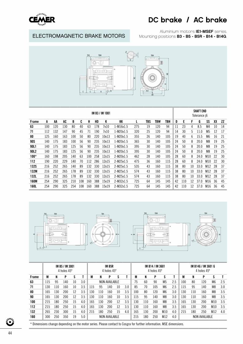
44
N
ET
TBHTBS TBW
M
4-S
P AC
L
Aluminium motors IE1-MSEF series.Mounting positions B3 - B5 - B5R - B14 - B14G.
IM B3 / IM 1001 SHAFT ENDTolerance j6
Frame A AA AC B C H HD K KK L TBS TBW TBH D E F G SS XX ZZ63 100 120 130 80 40 63 178 7x10 1-M16x1.5 275 19 120 94 11 23 4 8.5 M4 10 1471 112 132 147 90 45 71 190 7x10 1-M20x1.5 320 25 120 94 14 30 5 11.0 M5 12 1780 125 160 163 100 50 80 220 10x13 1-M20x1.5 355 26 140 105 19 40 6 15.5 M6 16 2190S 140 175 183 100 56 90 235 10x13 1-M20x1.5 365 30 140 105 24 50 8 20.0 M8 19 2590L1 140 175 183 125 56 90 235 10x13 1-M20x1.5 395 30 140 105 24 50 8 20.0 M8 19 2590L2 140 175 183 125 56 90 235 10x13 1-M20x1.5 395 30 140 105 24 50 8 20.0 M8 19 25100* 160 198 205 140 63 100 258 12x15 2-M20x1.5 462 28 140 105 28 60 8 24.0 M10 22 30112 190 220 229 140 70 112 286 12x15 2-M25x1.5 475 36 160 115 28 60 8 24.0 M10 22 30132S 216 252 265 140 89 132 330 12x15 2-M25x1.5 535 43 160 115 38 80 10 33.0 M12 28 37132M 216 252 265 178 89 132 330 12x15 2-M25x1.5 574 43 160 115 38 80 10 33.0 M12 28 37132L 216 252 265 178 89 132 330 12x15 2-M25x1.5 574 43 160 115 38 80 10 33.0 M12 28 37160M 254 290 325 210 108 160 388 15x19 2-M32x1.5 725 64 145 145 42 110 12 37.0 M16 36 45160L 254 290 325 254 108 160 388 15x19 2-M32x1.5 725 64 145 145 42 110 12 37.0 M16 36 45
IM B5 / IM 30014 holes 45º
IM B5R4 holes 45º
IM B14 / IM 36014 holes 45º
IM B14G / IM 3601 G4 holes 45º
Frame M N P S T M N P S T M N P S T M N P S T63 115 95 140 10 3.0 NON AVAILABLE 75 60 90 M5 2.5 100 80 120 M6 2.571 130 110 160 10 3.5 115 95 140 10 3.0 85 70 105 M6 2.5 115 95 140 M8 3.080 165 130 200 12 3.5 130 110 160 10 3.5 100 80 120 M6 3.0 130 110 160 M8 3.590 165 130 200 12 3.5 130 110 160 10 3.5 115 95 140 M8 3.0 130 110 160 M8 3.5100 215 180 250 15 4.0 165 130 200 12 3.5 130 110 160 M8 3.5 165 130 200 M10 3.5112 215 180 250 15 4.0 165 130 200 12 3.5 130 110 160 M8 3.5 165 130 200 M10 3.5132 265 230 300 15 4.0 215 180 250 15 4.0 165 130 200 M10 4.0 215 180 250 M12 4.0160 300 250 350 19 5.0 NON AVAILABLE 215 180 250 M12 4.0 NON AVAILABLE
* Dimensions change depending on the motor series. Please contact to Cosgra for further information. MSE dimensions.
LE T
TBS TBW TBH
4-S
MN PAC
AAA
TBHTBS TBW
E C B K
L
G
HD
ACF
D
H
A/2
DC brake / AC brake
ELECTROMAGNETIC BRAKE MOTORS
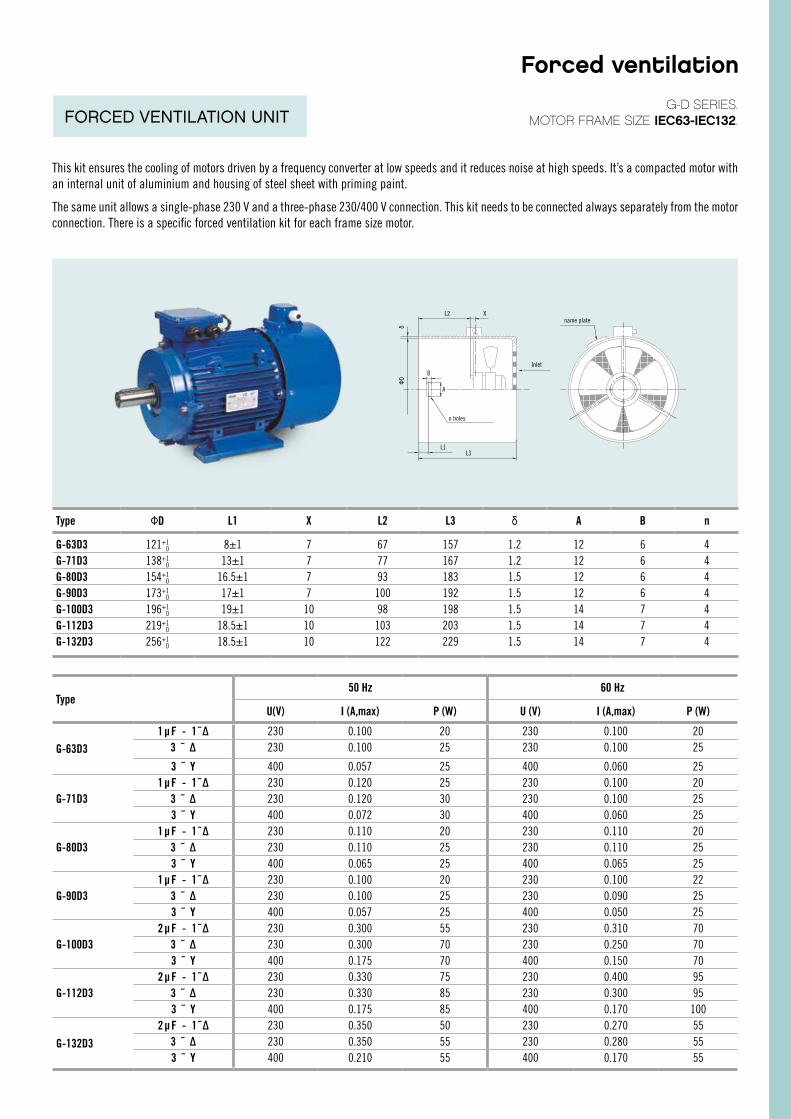
IM B5 / IM 30014 holes 45º
IM B5R4 holes 45º
IM B14 / IM 36014 holes 45º
IM B14G / IM 3601 G4 holes 45º
Frame M N P S T M N P S T M N P S T M N P S T63 115 95 140 10 3.0 NON AVAILABLE 75 60 90 M5 2.5 100 80 120 M6 2.571 130 110 160 10 3.5 115 95 140 10 3.0 85 70 105 M6 2.5 115 95 140 M8 3.080 165 130 200 12 3.5 130 110 160 10 3.5 100 80 120 M6 3.0 130 110 160 M8 3.590 165 130 200 12 3.5 130 110 160 10 3.5 115 95 140 M8 3.0 130 110 160 M8 3.5100 215 180 250 15 4.0 165 130 200 12 3.5 130 110 160 M8 3.5 165 130 200 M10 3.5112 215 180 250 15 4.0 165 130 200 12 3.5 130 110 160 M8 3.5 165 130 200 M10 3.5132 265 230 300 15 4.0 215 180 250 15 4.0 165 130 200 M10 4.0 215 180 250 M12 4.0160 300 250 350 19 5.0 NON AVAILABLE 215 180 250 M12 4.0 NON AVAILABLE
* Dimensions change depending on the motor series. Please contact to Cosgra for further information. MSE dimensions.
This kit ensures the cooling of motors driven by a frequency converter at low speeds and it reduces noise at high speeds. It’s a compacted motor with an internal unit of aluminium and housing of steel sheet with priming paint.
The same unit allows a single-phase 230 V and a three-phase 230/400 V connection. This kit needs to be connected always separately from the motor connection. There is a specific forced ventilation kit for each frame size motor.
Type ФD L1 X L2 L3 δ A B n
G-63D3 121+10 8±1 7 67 157 1.2 12 6 4
G-71D3 138+10 13±1 7 77 167 1.2 12 6 4
G-80D3 154+10 16.5±1 7 93 183 1.5 12 6 4
G-90D3 173+10 17±1 7 100 192 1.5 12 6 4
G-100D3 196+10 19±1 10 98 198 1.5 14 7 4
G-112D3 219+10 18.5±1 10 103 203 1.5 14 7 4
G-132D3 256+10 18.5±1 10 122 229 1.5 14 7 4
Type50 Hz 60 Hz
U(V) I (A,max) P (W) U (V) I (A,max) P (W)
G-63D31 µ F - 1 ˜ ∆ 230 0.100 20 230 0.100 20
3 ˜ ∆ 230 0.100 25 230 0.100 25
3 ˜ Y 400 0.057 25 400 0.060 25
G-71D31 µ F - 1 ˜ ∆ 230 0.120 25 230 0.100 20
3 ˜ ∆ 230 0.120 30 230 0.100 253 ˜ Y 400 0.072 30 400 0.060 25
G-80D31 µ F - 1 ˜ ∆ 230 0.110 20 230 0.110 20
3 ˜ ∆ 230 0.110 25 230 0.110 253 ˜ Y 400 0.065 25 400 0.065 25
G-90D31 µ F - 1 ˜ ∆ 230 0.100 20 230 0.100 22
3 ˜ ∆ 230 0.100 25 230 0.090 253 ˜ Y 400 0.057 25 400 0.050 25
G-100D32 µ F - 1 ˜ ∆ 230 0.300 55 230 0.310 70
3 ˜ ∆ 230 0.300 70 230 0.250 703 ˜ Y 400 0.175 70 400 0.150 70
G-112D32 µ F - 1 ˜ ∆ 230 0.330 75 230 0.400 95
3 ˜ ∆ 230 0.330 85 230 0.300 953 ˜ Y 400 0.175 85 400 0.170 100
G-132D3
2 µ F - 1 ˜ ∆ 230 0.350 50 230 0.270 553 ˜ ∆ 230 0.350 55 230 0.280 553 ˜ Y 400 0.210 55 400 0.170 55
L2 X
Inlet
L1L3
ФDδ
name plate
G-D SERIES.MOTOR FRAME SIZE IEC63-IEC132.
B
A
n holes
Forced ventilation
FORCED VENTILATION UNIT
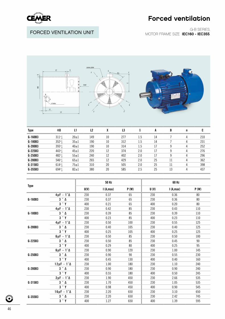
46
Type ФD L1 L2 X L3 δ A B n C
G-160B3 311+10 20±1 149 10 277 1.5 14 7 4 210
G-180B3 352+10 35±1 190 10 312 1.5 14 7 4 231
G-200B3 393+10 40±1 190 10 314 1.5 17 9 4 252
G-225B3 443+10 45±1 220 12 374 2.0 17 9 4 276
G-250B3 482+10 55±1 240 12 402 2.0 17 9 4 296
G-280B3 546+10 65±1 265 12 429 2.0 25 11 4 362
G-315B3 614+10 75±1 310 20 505 2.0 25 11 4 398
G-355B3 694+10 82±1 380 20 585 2.5 25 13 4 437
Type50 Hz 60 Hz
U(V) I (A,max) P (W) U (V) I (A,max) P (W)
G-160B34 µ F - 1 ˜ ∆ 230 0.37 65 230 0.36 80
3 ˜ ∆ 230 0.37 65 230 0.36 803 ˜ Y 400 0.21 65 400 0.20 80
G-180B34 µ F - 1 ˜ ∆ 230 0.42 85 230 0.43 110
3 ˜ ∆ 230 0.39 85 230 0.39 1103 ˜ Y 400 0.23 85 400 0.23 110
G-200B34 µ F - 1 ˜ ∆ 230 0.50 100 230 0.55 125
3 ˜ ∆ 230 0.40 105 230 0.40 1253 ˜ Y 400 0.25 105 400 0.25 125
G-225B36 µ F - 1 ˜ ∆ 230 0.50 85 230 0.50 100
3 ˜ ∆ 230 0.50 85 230 0.45 903 ˜ Y 400 0.29 80 400 0.25 95
G-250B36 µ F - 1 ˜ ∆ 230 0.90 120 230 1.00 145
3 ˜ ∆ 230 0.90 90 230 0.55 2303 ˜ Y 400 0.45 130 400 0.40 160
G-280B31 2 µ F - 1 ˜ ∆ 230 1.00 180 230 1.10 240
3 ˜ ∆ 230 0.90 180 230 0.90 2403 ˜ Y 400 0.55 180 400 0.50 245
G-315B32 µ F - 1 ˜ ∆ 230 1.90 450 230 2.66 535
3 ˜ ∆ 230 1.70 450 230 1.05 5353 ˜ Y 400 0.98 450 400 0.90 545
G-355B3
1 6 µ F - 1 ˜ ∆ 230 2.20 650 230 3.10 6503 ˜ ∆ 230 2.20 650 230 2.42 7453 ˜ Y 400 1.27 650 400 1.39 595
G-B SERIES.MOTOR FRAME SIZE IEC160 - IEC355.
L2 X
Inlet
n holes
L1L3 F F
F45ºF
E
C
E
E
ФDδ
name plate
B
A
Forced ventilation
FORCED VENTILATION UNIT
WARRANTIES, RETURNS AND COMPLAINTS
WARRANTIES
RETURNS AND COMPLAINTS
• COSGRA guarantees the motors it supplies against defective materials or manufacturing for a period of one year counted from the date of dispatch, taking the date given on the delivery note as valid, unless there is specific agreement in the offer or the acceptance of the order.
• Repairs are understood as taking place at COSGRA’S facilities, and the Purchaser will be responsible for paying the costs of dismantling, packaging, transport, Customs procedures, duties, etc. resulting from sending the equipment to COSGRA’S facilities and its subsequent delivery to the Purchaser.
• COSGRA may agree with the Purchaser to carry out repairs to defective parts or replacements at the Purchaser’s facilities. COSGRA will not pay for repairs carried out by third parties.
• The warranty consists of the repair or replacement of the parts that are faulty due to defective material or manufacturing. If appropriate, the defective motor will be entirely replaced with a new one, and the transport and new dispatch costs paid.
• The repair or replacement of a defective part will not change the date of the beginning of the warranty period for the equipment supplied. However, the part replaced or repaired will have a year’s warranty from its repair or replacement.
• Damage and the effects of normal wear and tear on the equipment are excluded from the warranty, as well as damage and defects caused by starting it up incorrectly, incorrect conservation or maintenance, erroneous storage or handling, modifications introduced without the written consent of COSGRA, and, in general, reasons not attributable to COSGRA.
• In all the circumstances set out in the above sections, COSGRA will not be responsible for defects in the motors and equipment supplied for more than one year from the date of dispatch.
• COSGRA will not under any circumstances be responsible for indirect and/or consequential damage that may occur as a result of the equipment supplied: loss of production, breakdowns or the cost of stoppages, etc.
• COSGRA’S full contractual responsibility deriving from the equipment supplied is limited to the value of the equipment supplied leading to the claim. This limitation will not apply to liability for direct injury to people or damage to property.
• The proper operation, conservation and maintenance of the equipment supplied is the exclusive responsibility and duty of care of the Purchaser or end user.
• COSGRA will not accept returns of equipment if they have not first been agreed with the Purchaser. A period of 15 days from receipt by the Purchaser of the goods supplied is established for it to notify COSGRA of its intention to return the equipment and the reason for this and to agree the procedure for returning it with COSGRA, as appropriate. Complaints from the Purchaser to COSGRA must always be made in writing and by reliable means.
• Transport costs must always be paid in cases of returns or dispatches of equipment to COSGRA’S facilities for refund, replacement or repair.
• COSGRA will not allow the return of equipment that has been used, fitted to other equipment or facilities, or dismantled without the involvement of COSGRA.
• COSGRA will not allow returns of products designed or manufactured specially for the order.
48
ASYNCHRONOUSTHREE-PHASE, SINGLE-PHASE ANDELECTROMAGNETICBRAKE MOTORS
EFFICIENCY CLASSACCORDING TO IEC 60034-30
2nd edition
ww
w.st
udid
f.co
m sacosgra
Ed.
MOT
ORES
CEM
ER 0
6/19
0.5
. W
e re
serv
e th
e rig
ht t
o m
ake
chan
ges
wit
hout
prio
r no
tice
.
sacosgraMECHANICAL SEALS FOR ROTARY SHAFTSAC ELECTRIC MOTORS: Single-phase / Three-phase / Self-braking / Anti-explosion / Flameproof / Variable speed DRUM MOTORS AND MOTORIZED DRUMSGEARBOXES: Worm gearbox / Pre-reduction / Double worm gearbox / Planetary speed variators / Coaxials / Speci�c
Ctra. de Banyoles a Figueres, Km 9 _ Telf. - +34 972 597 807Skype: cosgra.sa _ Fax +34 972 597 [email protected] _ 17832 CRESPIÀ (Girona) _ SPAINApartado 100 _ 17820 BANYOLES (Girona)(E) Esponellà Latitude: 42º10’42.6”N Longitude: 2º48’04.9”E Altitude: 120 m.
Sociedad Comercial COSGRA LATAM S.P.A. Alcalde Guzmán, 0121 - Quilicura - Santiago. [email protected] Telf: +56 944506061_+56 944644826_+56 956505381
w w w. c o s g r a . c o m